EP3988641A1 - Tank with door locking mechanism - Google Patents
Tank with door locking mechanism Download PDFInfo
- Publication number
- EP3988641A1 EP3988641A1 EP21197365.6A EP21197365A EP3988641A1 EP 3988641 A1 EP3988641 A1 EP 3988641A1 EP 21197365 A EP21197365 A EP 21197365A EP 3988641 A1 EP3988641 A1 EP 3988641A1
- Authority
- EP
- European Patent Office
- Prior art keywords
- tank
- door
- receiver
- arm
- receiver top
- Prior art date
- Legal status (The legal status is an assumption and is not a legal conclusion. Google has not performed a legal analysis and makes no representation as to the accuracy of the status listed.)
- Granted
Links
Images








Classifications
-
- E—FIXED CONSTRUCTIONS
- E05—LOCKS; KEYS; WINDOW OR DOOR FITTINGS; SAFES
- E05B—LOCKS; ACCESSORIES THEREFOR; HANDCUFFS
- E05B7/00—Handles pivoted about an axis parallel to the wing
-
- C—CHEMISTRY; METALLURGY
- C12—BIOCHEMISTRY; BEER; SPIRITS; WINE; VINEGAR; MICROBIOLOGY; ENZYMOLOGY; MUTATION OR GENETIC ENGINEERING
- C12M—APPARATUS FOR ENZYMOLOGY OR MICROBIOLOGY; APPARATUS FOR CULTURING MICROORGANISMS FOR PRODUCING BIOMASS, FOR GROWING CELLS OR FOR OBTAINING FERMENTATION OR METABOLIC PRODUCTS, i.e. BIOREACTORS OR FERMENTERS
- C12M23/00—Constructional details, e.g. recesses, hinges
- C12M23/46—Means for fastening
-
- B—PERFORMING OPERATIONS; TRANSPORTING
- B65—CONVEYING; PACKING; STORING; HANDLING THIN OR FILAMENTARY MATERIAL
- B65D—CONTAINERS FOR STORAGE OR TRANSPORT OF ARTICLES OR MATERIALS, e.g. BAGS, BARRELS, BOTTLES, BOXES, CANS, CARTONS, CRATES, DRUMS, JARS, TANKS, HOPPERS, FORWARDING CONTAINERS; ACCESSORIES, CLOSURES, OR FITTINGS THEREFOR; PACKAGING ELEMENTS; PACKAGES
- B65D90/00—Component parts, details or accessories for large containers
- B65D90/02—Wall construction
- B65D90/04—Linings
- B65D90/046—Flexible liners, e.g. loosely positioned in the container
-
- C—CHEMISTRY; METALLURGY
- C12—BIOCHEMISTRY; BEER; SPIRITS; WINE; VINEGAR; MICROBIOLOGY; ENZYMOLOGY; MUTATION OR GENETIC ENGINEERING
- C12M—APPARATUS FOR ENZYMOLOGY OR MICROBIOLOGY; APPARATUS FOR CULTURING MICROORGANISMS FOR PRODUCING BIOMASS, FOR GROWING CELLS OR FOR OBTAINING FERMENTATION OR METABOLIC PRODUCTS, i.e. BIOREACTORS OR FERMENTERS
- C12M23/00—Constructional details, e.g. recesses, hinges
- C12M23/02—Form or structure of the vessel
- C12M23/14—Bags
-
- C—CHEMISTRY; METALLURGY
- C12—BIOCHEMISTRY; BEER; SPIRITS; WINE; VINEGAR; MICROBIOLOGY; ENZYMOLOGY; MUTATION OR GENETIC ENGINEERING
- C12M—APPARATUS FOR ENZYMOLOGY OR MICROBIOLOGY; APPARATUS FOR CULTURING MICROORGANISMS FOR PRODUCING BIOMASS, FOR GROWING CELLS OR FOR OBTAINING FERMENTATION OR METABOLIC PRODUCTS, i.e. BIOREACTORS OR FERMENTERS
- C12M23/00—Constructional details, e.g. recesses, hinges
- C12M23/26—Constructional details, e.g. recesses, hinges flexible
Definitions
- Tanks are used in a variety of bioprocessing applications.
- a flexible container such as a bag can be placed in the tank, the door to the tank is closed and latched, and the bag is filled as part of the bioprocessing application.
- the present invention provides for ameliorating at least some of the disadvantages of the prior art.
- An aspect of the invention provides a tank with a door locking mechanism comprising: (a) a tank comprising a bottom wall, first and second opposing side walls, a rear wall, an outwardly pivoting tank door, a front wall having an opening, and a hinge mounted to the front wall and the outwardly pivoting tank door, wherein the outwardly pivoting tank door is arranged to cover at least a portion of the opening, the tank having an interior cavity for receiving an expandable bioprocessing container having flexible walls; the tank including a door locking mechanism comprising: (i) a rotatable shaft mounted to the outwardly pivoting tank door, the rotatable shaft having a first end and a second end, the second end comprising a projecting arm; and, (ii) an arm receiver, comprising a base mounted to the front wall of the tank at a distance from the outwardly pivoting tank door and the rotatable shaft, the arm receiver further comprising a receiver top extending horizontally from the base, the receiver top comprising a receiver top
- a tank with a door locking mechanism comprising (a) a tank comprising a housing having an interior cavity for receiving an expandable bioprocessing container having flexible walls; a bottom wall; a side wall, wherein the side wall has an opening; an outwardly pivoting tank door; and a hinge mounted to the side wall and the outwardly pivoting tank door, wherein the outwardly pivoting tank door is arranged to cover at least a portion of the opening; the tank including a door locking mechanism comprising: (i) a rotatable shaft mounted to the outwardly pivoting tank door, the rotatable shaft having a first end and a second end, the second end comprising a projecting arm; and, (ii) an arm receiver, comprising a base mounted to the at least one side wall of the tank at a distance from the outwardly pivoting tank door and the rotatable shaft, the arm receiver further comprising a receiver top extending horizontally from the base, the receiver top comprising a receiver top wall, first and second
- a method of operating the tank with the door locking mechanism comprises placing a bioprocessing container with flexible walls into the interior cavity of an aspect of the tank; rotating the rotatable shaft until the projecting arm aligns with the arm receiver opening; inflating the bioprocessing container with air or gas and/or filling the bioprocessing container with fluid until the bioprocessing container expands and a flexible wall of the expanded bioprocessing container contacts the pivoting tank door and the pivoting tank door pivots outwardly.
- a tank with a door locking mechanism comprises: (a) a tank comprising a bottom wall, first and second opposing side walls, a rear wall, an outwardly pivoting tank door, a front wall having an opening, and a hinge mounted to the front wall and the outwardly pivoting tank door, wherein the outwardly pivoting tank door is arranged to cover at least a portion of the opening, the tank having an interior cavity for receiving an expandable bioprocessing container with flexible walls; the tank including a door locking mechanism comprising: (i) a rotatable shaft mounted to the outwardly pivoting tank door, the rotatable shaft having a first end and a second end, the second end comprising a projecting arm; and, (ii) an arm receiver, comprising a base mounted to the front wall of the tank at a distance from the outwardly pivoting tank door and the rotatable shaft, the arm receiver further comprising a receiver top extending horizontally from the base, the receiver top comprising a
- a tank with a door locking mechanism comprising (a) a tank comprising a housing having an interior cavity for receiving an expandable bioprocessing container having flexible walls; a bottom wall; a side wall, wherein the side wall has an opening; an outwardly pivoting tank door; and a hinge mounted to the side wall and the outwardly pivoting tank door, wherein the outwardly pivoting tank door is arranged to cover at least a portion of the opening;
- the tank including a door locking mechanism comprising: (i) a rotatable shaft mounted to the outwardly pivoting tank door, the rotatable shaft having a first end and a second end, the second end comprising a projecting arm; and, (ii) an arm receiver, comprising a base mounted to the at least one side wall of the tank at a distance from the outwardly pivoting tank door and the rotatable shaft, the arm receiver further comprising a receiver top extending horizontally from the base, the receiver top comprising a receiver top
- the tank door includes at least one extension providing a door stop preventing the tank door from entering the internal cavity of the tank.
- the door locking mechanism can be manually and/or electronically controlled.
- the door locking mechanism is manually controlled without automation or electronics, thus reducing complexity and cost.
- Tanks can include any number of door locking mechanisms.
- a method of operating the tank with the door locking mechanism comprising placing a bioprocessing container with flexible walls into the interior cavity of an aspect of the tank; rotating the rotatable shaft until the projecting arm aligns with the arm receiver opening; and, inflating the bioprocessing container with air or gas and/or filling the bioprocessing container with fluid until the bioprocessing container expands and a flexible wall of the expanded bioprocessing container contacts the pivoting tank door and the pivoting tank door pivots outwardly.
- the bioprocessing container is inflated with air or gas followed by filling with liquid.
- method includes pivoting the pivoting door outwardly until the projecting arm contacts the bottom end of receiver top bottom wall.
- an external lock can be attached to the locked door locking mechanism to reduce the chance that the door would open during transport and/or to prevent unauthorized opening.
- Door locking mechanisms can be used with a variety of tanks, including commercially available tanks.
- Tanks can have more than 1 door, as shown in, for example, Figure 7 , and/or tanks can have any suitable shape, including rounded, with a curved door, as shown in, for example, Figure 8 .
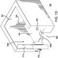
- FIG 1A is a perspective view of a tank 500 (also shown in Figures 1D-1G , and 5) including a door locking mechanism 300 according to an aspect of the invention, wherein the tank door is closed
- Figure ID is perspective view of the tank 500 including the door mechanism as shown in Figure 1A , wherein the door is partially open.
- the illustrated aspect of the tank 500 in Figure 1A comprises an open top 501 (if desired, the tank can include a top wall (not shown); a bottom wall 502, first and second opposing side walls 503, 504, a rear wall 505 (having top walls 503A, 504A, and 505A, respectively), an outwardly pivoting tank door 510 (having a top wall 510A; in some aspects wherein the tank includes a top wall, the tank door does not provide part of the top wall of the tank), a front wall 506 having an opening 506A, and at least one hinge 600 (two hinges are shown) mounted to the front wall and the outwardly pivoting tank door, wherein the outwardly pivoting tank door is arranged to cover at least a portion of the opening, the tank having an interior cavity 520 for receiving an expandable bioprocessing container 700 (see, Figures IF and 6A-6C) with flexible walls, the interior cavity having a floor 525.
- the tank can include a top wall (not shown); a bottom wall 50
- the lower portion of the tank extends below floor 525 of the interior cavity 520, providing a base for the tank.
- the opening 506A can be larger than the tank door 510, e.g., due due to small gaps between the door and the door opening, and due to space below the bottom of the door.
- the tank door 510 covers a major portion (e.g., at least about 60%, and in some embodiments, at least about 80% of the area) of the opening 506A.
- the illustrated door locking mechanism 300 comprises a rotatable shaft 100 (rotatable between a first (unlocked) position 101 ( see, Figure 3 ) and a second (locked) position 102 ( see, Figures 1A , 1C , and 3 )) mounted to the outwardly pivoting tank door 510, the rotatable shaft having a first end 151 comprising a handle 161 and a second end 152 comprising a projecting arm 162; and, an arm receiver 200 ( see, Figure 4 ), comprising a base 250 mounted to the front wall 506 of the tank 500 at a distance from the outwardly pivoting tank door 510 and the rotatable shaft 100, the arm receiver 200 further comprising a receiver top 275 extending horizontally from the base, the receiver top comprising a receiver top wall 281, inner walls 287 and 288, first and second opposing receiver top side walls 283, 284, a receiver top rear wall 285, and a receiver top front wall 286 having a bottom end 286A, the receiver top opposing side walls
- the tank door 510 has a top end 511, bottom end 512, front end 513, a rear end 514, an outer surface 515 and an inner surface 516 (see, Figure 5 ; in some aspects, the inner surface of the door does not contact the tank, e.g., as in Figures 1A-1C , and 1E-1G ); and at least one hinge 600 mounted to the door 510 (two hinges are illustrated as mounted to an edge of the rear end 514 and on the outer surface of the front wall 506 of the tank). Aspects of the invention can have a plurality of hinges; typically, if there is a single hinge, it may mounted approximately half way between the top and bottom ends of the door.
- FIG 7 illustrates a tank 500' according to another aspect of the invention, similar to the illustrated aspect of the tank 500 shown in Figure 1A , however, tank 500' includes a pair of outwardly pivoting tank doors 510 (each covering an opening 506A) and a corresponding pair of door locking mechanisms 300 as described above.
- the interior cavity and interior cavity floor are not shown.
- FIG 8 illustrates a tank 500" according to another aspect of the invention, including an outwardly pivoting tank door 510", and a door locking mechanism 300 as described above.
- tank 500 has a rounded shape with a continuous curved side wall 509" and the outwardly pivoting tank door 510" is curved (and covers opening 509A").
- outwardly pivoting tank door 510 being curved
- the tank door 510" is similar in structure to outwardly pivoting tank door 510 as described above.
- the views of the interior cavity 520 for receiving an expandable bioprocessing container 700 with flexible walls, wherein the interior cavity has a floor 525, are blocked by the door 510".
- aspects of the invention can have any number of door locking mechanisms 300.
- the rotatable shaft may be mounted approximately half way between the top and bottom ends of the door.
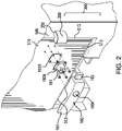
- the rotatable shaft 100 rotates around a collar 191 mounted to a flange 192A which is mounted to a gasket 192B mounted to the door.
- the door locking mechanism 300 is mounted such that the arm receiver 200 (mounted on the outer surface 515 of the front wall 506 of the tank near the front end 513 of the tank door) is aligned with the rotatable shaft 100, and the projecting arm 162 can be rotated to be received in the receiver top 275 and the arm receiver opening 290, and in some aspects, until the projecting arm contacts the bottom end 286A of the receiver top bottom wall that provides a stop for the projecting arm ( see, Figures 1C and 4 ).
- the locking mechanism 300 arranged such that the arm receiver is located near the front end 513 of the tank door
- the locking mechanism can be arranged such that the arm receiver is located near the top end or bottom end of the tank door.
- the rotatable shaft can have a variety of configurations as long as it can be rotatably mounted to the tank door, and the projecting arm can be aligned with the receiver top once the tank door pivots outwardly as described herein.
- a variety of rotatable shafts are suitable, including commercially available rotatable shafts.
- the rotatable shaft can include a safety feature such as a lock button 100A as shown in Figure 2 , wherein the rotatable shaft can only be rotated when the lock button is pushed and held.
- Suitable rotatable shafts with lock buttons includes those available from, for example, Southco, Inc. (Concordville, PA).
- the door 510 includes at least one extension 586 providing a door stop preventing the door from entering the internal cavity 520 of the tank.
- Figure 5 shows two extensions, 586A, 586B, arranged to contact the front wall 506 preventing the door from entering the internal cavity 520.
- the tank allows the interior to be viewed, e.g., to monitor the filling of the bioprocessing container.
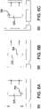
- Figures 5 and 6A-6C show a window 575 in the door 510, wherein Figures 6A-6C show the bioprocessing container 700 being filled with liquid.
- bioprocessing container also includes, for example, various fluid ports on the container to allow fluid to enter and exit the container, and, for example, if desired, for sampling the contents of the container and/or venting and/or adding reagents and/or buffers (and tubing is connected to the various fluid ports), for ease of viewing, only a single tube 701A connected to fluid port 701 is shown in Figure IF, and Figure 5 shows bioprocessing container fluid ports 701 and 702, wherein additional tubing and fluid ports are not illustrated.
- aspects of the invention can also include a bracket allowing an external lock to be attached to the locked door locking mechanism to reduce the chance that the door would open during transport and/or to prevent unauthorized opening.
- Figure 9 shows a bracket 800, illustrated as having a generally "U-shaped" opening allowing the bracket to fit over the arm receiver with the projecting arm received in the arm receiver, wherein the bracket has arms 810 with holes 810A allowing a lock 850 to be mounted to the bracket to prevent opening.
- a warning label can be included, e.g., affixed to the lock and/or the bracket.
- bioprocessing containers with flexible walls are suitable for use in aspects of the invention and are commercially available.
- the bioprocessing containers can have, for example, any suitable shape and volume.
- the bioprocessing containers have at least two, and in some aspects, 3 or more, fluid ports, and connected tubing.
- Figure 5 shows bioprocessing container fluid ports 701 and 702.
- an aspect of the method comprises placing a bioprocessing container with flexible walls into the interior cavity 520 of an aspect of the tank (e.g., including routing bioprocessing container tubing and/or arranging bioprocessing container ports in one or more cutouts such as 805 as shown in Figures 1A and 5 , and cutout 806 as shown in Figure 5 , and/or in one or more cutouts, e.g., 805A, in the floor 525 as shown in Figures 1A , ID, IE and 1G); rotating the rotatable shaft until the projecting arm until the projecting arm aligns with the arm receiver opening ( see, Figures 3 and 1A ); filling the bioprocessing container with fluid (see, Figures IF and 6A-6C) until the bioprocessing container expands and a flexible wall of the expanded bioprocessing container contacts the pivoting tank door and the pivoting tank door pivots outwardly ( see
- one option for bioprocessing includes mixing, wherein a mixer (e.g., a removable mixer drive unit (for example, inserted in an opening 900 in the floor 525 as shown Figure IF) or a mixer fixed to the tank through the opening) is activated, powders and/or fluids are added to mix or regulate the product inside the container.
- a mixer e.g., a removable mixer drive unit (for example, inserted in an opening 900 in the floor 525 as shown Figure IF) or a mixer fixed to the tank through the opening
- the tank may include jacketed walls allowing the contents of the bioprocessing container to be heated and/or cooled.
- the bioprocessing container After mixing and/or heating and/or cooling, the bioprocessing container is drained through the drain port. After draining, the door can be opened again and the bioprocessing container can be removed.
Landscapes
- Health & Medical Sciences (AREA)
- Engineering & Computer Science (AREA)
- Organic Chemistry (AREA)
- Life Sciences & Earth Sciences (AREA)
- Bioinformatics & Cheminformatics (AREA)
- Chemical & Material Sciences (AREA)
- Zoology (AREA)
- Wood Science & Technology (AREA)
- Sustainable Development (AREA)
- Microbiology (AREA)
- Biotechnology (AREA)
- Biomedical Technology (AREA)
- Biochemistry (AREA)
- General Engineering & Computer Science (AREA)
- General Health & Medical Sciences (AREA)
- Genetics & Genomics (AREA)
- Clinical Laboratory Science (AREA)
- Mechanical Engineering (AREA)
- Apparatus Associated With Microorganisms And Enzymes (AREA)
Abstract
Description
- Tanks are used in a variety of bioprocessing applications. For example, a flexible container such as a bag can be placed in the tank, the door to the tank is closed and latched, and the bag is filled as part of the bioprocessing application.
- However, there is a need for improved latches for tanks that receive flexible containers for bioprocessing applications.
- The present invention provides for ameliorating at least some of the disadvantages of the prior art. These and other advantages of the present invention will be apparent from the description as set forth below.
- An aspect of the invention provides a tank with a door locking mechanism comprising: (a) a tank comprising a bottom wall, first and second opposing side walls, a rear wall, an outwardly pivoting tank door, a front wall having an opening, and a hinge mounted to the front wall and the outwardly pivoting tank door, wherein the outwardly pivoting tank door is arranged to cover at least a portion of the opening, the tank having an interior cavity for receiving an expandable bioprocessing container having flexible walls; the tank including a door locking mechanism comprising: (i) a rotatable shaft mounted to the outwardly pivoting tank door, the rotatable shaft having a first end and a second end, the second end comprising a projecting arm; and, (ii) an arm receiver, comprising a base mounted to the front wall of the tank at a distance from the outwardly pivoting tank door and the rotatable shaft, the arm receiver further comprising a receiver top extending horizontally from the base, the receiver top comprising a receiver top wall, first and second opposing receiver top side walls, a receiver top rear wall, and a receiver top front wall having a bottom end, the receiver top opposing side walls each extending toward the base a distance past the bottom end of the receiver top front wall; the bottom end of the receiver top front wall and first and second opposing receiver top side walls defining an arm receiver opening for receiving the projecting arm when the rotatable shaft is rotated to align the projecting arm with the arm receiver opening, and the outwardly pivoting tank door pivots outwardly upon being contacted by an expanded bioprocessing container.
- Another aspect of the invention comprises a tank with a door locking mechanism comprising (a) a tank comprising a housing having an interior cavity for receiving an expandable bioprocessing container having flexible walls; a bottom wall; a side wall, wherein the side wall has an opening; an outwardly pivoting tank door; and a hinge mounted to the side wall and the outwardly pivoting tank door, wherein the outwardly pivoting tank door is arranged to cover at least a portion of the opening; the tank including a door locking mechanism comprising: (i) a rotatable shaft mounted to the outwardly pivoting tank door, the rotatable shaft having a first end and a second end, the second end comprising a projecting arm; and, (ii) an arm receiver, comprising a base mounted to the at least one side wall of the tank at a distance from the outwardly pivoting tank door and the rotatable shaft, the arm receiver further comprising a receiver top extending horizontally from the base, the receiver top comprising a receiver top wall, first and second opposing receiver top side walls, a receiver top rear wall, and a receiver top front wall having a bottom end, the receiver top opposing side walls each extending toward the base a distance past the bottom end of the receiver top front wall; the bottom end of the receiver top front wall and first and second opposing receiver top side walls defining an arm receiver opening for receiving the projecting arm when the rotatable shaft is rotated to align the projecting arm with the arm receiver opening, and the outwardly pivoting tank door pivots outwardly upon being contacted by an expanded bioprocessing container.
- In another aspect, a method of operating the tank with the door locking mechanism is provided. In a preferred aspect, the method comprises placing a bioprocessing container with flexible walls into the interior cavity of an aspect of the tank; rotating the rotatable shaft until the projecting arm aligns with the arm receiver opening; inflating the bioprocessing container with air or gas and/or filling the bioprocessing container with fluid until the bioprocessing container expands and a flexible wall of the expanded bioprocessing container contacts the pivoting tank door and the pivoting tank door pivots outwardly.
-
-
Figure 1A is a front perspective view of a tank including a door locking mechanism comprising a rotatable shaft comprising a handle and a projecting arm; and an arm receiver; mounted to the tank according to an aspect of the invention, wherein the tank door is pivoted outwardly and the door locking mechanism and the tank door are locked with the projecting arm received by the arm receiver;Figure 1B is top view of a door locking mechanism, wherein the rotatable shaft is attached to a hinged tank door, and the arm receiver is attached to the front wall of the tank, wherein the projecting arm is not received in the arm receiver;Figure 1C is top view of a door locking mechanism shown inFigure 1A , wherein the tank door is pivoted outwardly and the door locking mechanism and the tank door are locked with the projecting arm received by the arm receiver; Figure ID is a perspective view of the tank shown inFigure 1A , with the tank door partially open; Figure IE is a top view of the tank shown inFigure 1A , with the tank door closed; Figure IF is a top view of the tank shown inFigure 1A , also showing an expanded bioprocessing container in the tank contacting the tank door and causing the tank door to pivot outwardly; andFigure 1G is a top view of another tank similar to that shown inFigure 1A , wherein the floor of the tank includes an opening allowing the insertion of a removable mixer drive unit, or for mounting a mixer. -
Figure 2 is a perspective side view showing mounting the rotatable shaft to the hinged tank door. -
Figure 3 shows rotation of the rotatable shaft upwardly and downwardly. -
Figure 4 shows a perspective view of the arm receiver of the door locking mechanism shown inFigures 1A and1B . -
Figure 5 shows a perspective of view of a tank with opposing side walls and including two door locking mechanisms according to an aspect of the invention, also showing upper and lower door stops preventing the door from pivoting into the interior cavity of the tank, and showing cutouts for tubing and/or ports connected to a bioprocessing container that can be placed in the tank. -
Figures 6A-6C show filling of a bioprocessing container in the tank, whereinFigure 6A shows fluid initially entering the container,Figure 6B shows the container approximately halfway filled, andFigure 6C shows the container filled. -
Figure 7 is a perspective view of a tank with opposing side walls and two doors and including a door locking mechanism associated with each door according to an aspect of the invention. -
Figure 8 is a perspective view of a tank with a continuous curved side wall and including a door locking mechanism according to an aspect of the invention. -
Figure 9 shows that an external lock can be attached to the locked door locking mechanism shown inFigure 1C , preventing rotation of the rotatable shaft. - In accordance with an aspect of the invention, a tank with a door locking mechanism comprises: (a) a tank comprising a bottom wall, first and second opposing side walls, a rear wall, an outwardly pivoting tank door, a front wall having an opening, and a hinge mounted to the front wall and the outwardly pivoting tank door, wherein the outwardly pivoting tank door is arranged to cover at least a portion of the opening, the tank having an interior cavity for receiving an expandable bioprocessing container with flexible walls; the tank including a door locking mechanism comprising: (i) a rotatable shaft mounted to the outwardly pivoting tank door, the rotatable shaft having a first end and a second end, the second end comprising a projecting arm; and, (ii) an arm receiver, comprising a base mounted to the front wall of the tank at a distance from the outwardly pivoting tank door and the rotatable shaft, the arm receiver further comprising a receiver top extending horizontally from the base, the receiver top comprising a receiver top wall, first and second opposing receiver top side walls, a receiver top rear wall, and a receiver top front wall having a bottom end, the receiver top opposing side walls each extending toward the base a distance past the bottom end of the receiver top front wall; the bottom end of the receiver top front wall and first and second opposing receiver top side walls defining an arm receiver opening for receiving the projecting arm when the rotatable shaft is rotated to align the projecting arm with the arm receiver opening, and the outwardly pivoting tank door pivots outwardly upon being contacted by an expanded bioprocessing container.
- In accordance with another aspect of the invention a tank with a door locking mechanism is provided comprising (a) a tank comprising a housing having an interior cavity for receiving an expandable bioprocessing container having flexible walls; a bottom wall; a side wall, wherein the side wall has an opening; an outwardly pivoting tank door; and a hinge mounted to the side wall and the outwardly pivoting tank door, wherein the outwardly pivoting tank door is arranged to cover at least a portion of the opening; the tank including a door locking mechanism comprising: (i) a rotatable shaft mounted to the outwardly pivoting tank door, the rotatable shaft having a first end and a second end, the second end comprising a projecting arm; and, (ii) an arm receiver, comprising a base mounted to the at least one side wall of the tank at a distance from the outwardly pivoting tank door and the rotatable shaft, the arm receiver further comprising a receiver top extending horizontally from the base, the receiver top comprising a receiver top wall, first and second opposing receiver top side walls, a receiver top rear wall, and a receiver top front wall having a bottom end, the receiver top opposing side walls each extending toward the base a distance past the bottom end of the receiver top front wall; the bottom end of the receiver top front wall and first and second opposing receiver top side walls defining an arm receiver opening for receiving the projecting arm when the rotatable shaft is rotated to align the projecting arm with the arm receiver opening, and the outwardly pivoting tank door pivots outwardly upon being contacted by an expanded bioprocessing container.
- In some aspects, the tank door includes at least one extension providing a door stop preventing the tank door from entering the internal cavity of the tank.
- Aspects of the door locking mechanism can be manually and/or electronically controlled. Preferably, the door locking mechanism is manually controlled without automation or electronics, thus reducing complexity and cost.
- Tanks can include any number of door locking mechanisms.
- In another aspect, a method of operating the tank with the door locking mechanism is provided, the method comprising placing a bioprocessing container with flexible walls into the interior cavity of an aspect of the tank; rotating the rotatable shaft until the projecting arm aligns with the arm receiver opening; and, inflating the bioprocessing container with air or gas and/or filling the bioprocessing container with fluid until the bioprocessing container expands and a flexible wall of the expanded bioprocessing container contacts the pivoting tank door and the pivoting tank door pivots outwardly. In some aspects, the bioprocessing container is inflated with air or gas followed by filling with liquid.
- In a preferred aspect, method includes pivoting the pivoting door outwardly until the projecting arm contacts the bottom end of receiver top bottom wall.
- Advantageously, since a user is unable to open a tank when the container inside the tank is at least partially filed, possible injury to the user is avoided. If desired, an external lock can be attached to the locked door locking mechanism to reduce the chance that the door would open during transport and/or to prevent unauthorized opening.
- Door locking mechanisms can be used with a variety of tanks, including commercially available tanks. Tanks can have more than 1 door, as shown in, for example,
Figure 7 , and/or tanks can have any suitable shape, including rounded, with a curved door, as shown in, for example,Figure 8 . - Each of the components of the invention will now be described in more detail below, wherein like components have like reference numbers.
-
Figure 1A is a perspective view of a tank 500 (also shown inFigures 1D-1G , and 5) including adoor locking mechanism 300 according to an aspect of the invention, wherein the tank door is closed, Figure ID is perspective view of thetank 500 including the door mechanism as shown inFigure 1A , wherein the door is partially open. - The illustrated aspect of the
tank 500 inFigure 1A comprises an open top 501 (if desired, the tank can include a top wall (not shown); abottom wall 502, first and secondopposing side walls top walls top wall 510A; in some aspects wherein the tank includes a top wall, the tank door does not provide part of the top wall of the tank), afront wall 506 having an opening 506A, and at least one hinge 600 (two hinges are shown) mounted to the front wall and the outwardly pivoting tank door, wherein the outwardly pivoting tank door is arranged to cover at least a portion of the opening, the tank having aninterior cavity 520 for receiving an expandable bioprocessing container 700 (see, Figures IF and 6A-6C) with flexible walls, the interior cavity having afloor 525. - Typically, as shown in
Figures 1A , ID, and 5, the lower portion of the tank extends belowfloor 525 of theinterior cavity 520, providing a base for the tank. If desired, the opening 506A can be larger than thetank door 510, e.g., due due to small gaps between the door and the door opening, and due to space below the bottom of the door. However, thetank door 510 covers a major portion (e.g., at least about 60%, and in some embodiments, at least about 80% of the area) of the opening 506A. - The illustrated
door locking mechanism 300 comprises a rotatable shaft 100 (rotatable between a first (unlocked) position 101 (see,Figure 3 ) and a second (locked) position 102 (see,Figures 1A ,1C , and3 )) mounted to the outwardlypivoting tank door 510, the rotatable shaft having afirst end 151 comprising ahandle 161 and asecond end 152 comprising a projectingarm 162; and, an arm receiver 200 (see,Figure 4 ), comprising abase 250 mounted to thefront wall 506 of thetank 500 at a distance from the outwardlypivoting tank door 510 and therotatable shaft 100, thearm receiver 200 further comprising areceiver top 275 extending horizontally from the base, the receiver top comprising a receivertop wall 281,inner walls top side walls rear wall 285, and a receivertop front wall 286 having abottom end 286A, the receiver top opposing side walls each extending toward the base a distance "X" past the bottom end of the receiver top front wall; the bottom end of the receiver top front wall and first and second opposing receiver top side walls defining an arm receiver opening 290 for receiving the projecting arm when the rotatable shaft is rotated to align the projecting arm with the arm receiver opening, and the outwardly pivoting tank door pivots outwardly (see,Figures 1B, 1C , and IF) upon being contacted by an expanded bioprocessing container. - The
tank door 510 has atop end 511,bottom end 512,front end 513, arear end 514, anouter surface 515 and an inner surface 516 (see,Figure 5 ; in some aspects, the inner surface of the door does not contact the tank, e.g., as inFigures 1A-1C , and1E-1G ); and at least onehinge 600 mounted to the door 510 (two hinges are illustrated as mounted to an edge of therear end 514 and on the outer surface of thefront wall 506 of the tank). Aspects of the invention can have a plurality of hinges; typically, if there is a single hinge, it may mounted approximately half way between the top and bottom ends of the door. -
Figure 7 illustrates a tank 500' according to another aspect of the invention, similar to the illustrated aspect of thetank 500 shown inFigure 1A , however, tank 500' includes a pair of outwardly pivoting tank doors 510 (each covering an opening 506A) and a corresponding pair ofdoor locking mechanisms 300 as described above. The interior cavity and interior cavity floor are not shown. - As noted above, tanks can have any suitable shape.
Figure 8 illustrates atank 500" according to another aspect of the invention, including an outwardlypivoting tank door 510", and adoor locking mechanism 300 as described above. However, in contrast withtanks 500 and 500',tank 500" has a rounded shape with a continuouscurved side wall 509" and the outwardlypivoting tank door 510" is curved (and covers opening 509A"). With the exception of outwardlypivoting tank door 510" being curved, thetank door 510" is similar in structure to outwardly pivotingtank door 510 as described above. The views of theinterior cavity 520 for receiving anexpandable bioprocessing container 700 with flexible walls, wherein the interior cavity has afloor 525, are blocked by thedoor 510". - Aspects of the invention can have any number of
door locking mechanisms 300. Typically, if there is a single door locking mechanism, the rotatable shaft may be mounted approximately half way between the top and bottom ends of the door. - As is known in the art, there are a number of arrangements and configurations for mounting the rotatable shaft to the door. As shown in
Figure 2 , therotatable shaft 100 rotates around acollar 191 mounted to aflange 192A which is mounted to agasket 192B mounted to the door. As shown inFigures 2 and3 , thedoor locking mechanism 300 is mounted such that the arm receiver 200 (mounted on theouter surface 515 of thefront wall 506 of the tank near thefront end 513 of the tank door) is aligned with therotatable shaft 100, and the projectingarm 162 can be rotated to be received in thereceiver top 275 and the arm receiver opening 290, and in some aspects, until the projecting arm contacts thebottom end 286A of the receiver top bottom wall that provides a stop for the projecting arm (see,Figures 1C and4 ). - While the Figures illustrate the
locking mechanism 300 arranged such that the arm receiver is located near thefront end 513 of the tank door, other arrangements are within the scope of the invention, for example, the locking mechanism can be arranged such that the arm receiver is located near the top end or bottom end of the tank door. - The rotatable shaft can have a variety of configurations as long as it can be rotatably mounted to the tank door, and the projecting arm can be aligned with the receiver top once the tank door pivots outwardly as described herein. A variety of rotatable shafts are suitable, including commercially available rotatable shafts. If desired, the rotatable shaft can include a safety feature such as a
lock button 100A as shown inFigure 2 , wherein the rotatable shaft can only be rotated when the lock button is pushed and held. Suitable rotatable shafts with lock buttons includes those available from, for example, Southco, Inc. (Concordville, PA). - In some aspects, the
door 510 includes at least oneextension 586 providing a door stop preventing the door from entering theinternal cavity 520 of the tank. For example,Figure 5 shows two extensions, 586A, 586B, arranged to contact thefront wall 506 preventing the door from entering theinternal cavity 520. - In some aspects, the tank allows the interior to be viewed, e.g., to monitor the filling of the bioprocessing container. For example,
Figures 5 and6A-6C show awindow 575 in thedoor 510, whereinFigures 6A-6C show thebioprocessing container 700 being filled with liquid. While the bioprocessing container also includes, for example, various fluid ports on the container to allow fluid to enter and exit the container, and, for example, if desired, for sampling the contents of the container and/or venting and/or adding reagents and/or buffers (and tubing is connected to the various fluid ports), for ease of viewing, only asingle tube 701A connected tofluid port 701 is shown in Figure IF, andFigure 5 shows bioprocessingcontainer fluid ports - If desired, aspects of the invention can also include a bracket allowing an external lock to be attached to the locked door locking mechanism to reduce the chance that the door would open during transport and/or to prevent unauthorized opening. For example,
Figure 9 shows abracket 800, illustrated as having a generally "U-shaped" opening allowing the bracket to fit over the arm receiver with the projecting arm received in the arm receiver, wherein the bracket hasarms 810 withholes 810A allowing alock 850 to be mounted to the bracket to prevent opening. If desired, a warning label can be included, e.g., affixed to the lock and/or the bracket. - A variety of bioprocessing containers with flexible walls are suitable for use in aspects of the invention and are commercially available. The bioprocessing containers can have, for example, any suitable shape and volume. Typically, the bioprocessing containers have at least two, and in some aspects, 3 or more, fluid ports, and connected tubing. For example,
Figure 5 shows bioprocessingcontainer fluid ports - Aspects of the invention include a method of operating the tank with the door locking mechanism during a bioprocessing application. For example, an aspect of the method comprises placing a bioprocessing container with flexible walls into the
interior cavity 520 of an aspect of the tank (e.g., including routing bioprocessing container tubing and/or arranging bioprocessing container ports in one or more cutouts such as 805 as shown inFigures 1A and5 , andcutout 806 as shown inFigure 5 , and/or in one or more cutouts, e.g., 805A, in thefloor 525 as shown inFigures 1A , ID, IE and 1G); rotating the rotatable shaft until the projecting arm until the projecting arm aligns with the arm receiver opening (see,Figures 3 and1A ); filling the bioprocessing container with fluid (see, Figures IF and 6A-6C) until the bioprocessing container expands and a flexible wall of the expanded bioprocessing container contacts the pivoting tank door and the pivoting tank door pivots outwardly (see,Figures 1C , and1E-1G (showing the door pivoted outwardly; Figure IF showing an expandedbioprocessing container 700 contacting the tank door causing it to pivot outwardly)). - Depending on the bioprocessing application, after filling the bioprocessing container, one option for bioprocessing includes mixing, wherein a mixer (e.g., a removable mixer drive unit (for example, inserted in an
opening 900 in thefloor 525 as shown Figure IF) or a mixer fixed to the tank through the opening) is activated, powders and/or fluids are added to mix or regulate the product inside the container. Alternatively, or additionally, the tank may include jacketed walls allowing the contents of the bioprocessing container to be heated and/or cooled. - After mixing and/or heating and/or cooling, the bioprocessing container is drained through the drain port. After draining, the door can be opened again and the bioprocessing container can be removed.
- All references, including publications, patent applications, and patents, cited herein are hereby incorporated by reference to the same extent as if each reference were individually and specifically indicated to be incorporated by reference and were set forth in its entirety herein.
- The use of the terms "a" and "an" and "the" and "at least one" and similar referents in the context of describing the invention (especially in the context of the following claims) are to be construed to cover both the singular and the plural, unless otherwise indicated herein or clearly contradicted by context. The use of the term "at least one" followed by a list of one or more items (for example, "at least one of A and B") is to be construed to mean one item selected from the listed items (A or B) or any combination of two or more of the listed items (A and B), unless otherwise indicated herein or clearly contradicted by context. The terms "comprising," "having," "including," and "containing" are to be construed as open-ended terms (i.e., meaning "including, but not limited to,") unless otherwise noted. Recitation of ranges of values herein are merely intended to serve as a shorthand method of referring individually to each separate value falling within the range, unless otherwise indicated herein, and each separate value is incorporated into the specification as if it were individually recited herein. All methods described herein can be performed in any suitable order unless otherwise indicated herein or otherwise clearly contradicted by context. The use of any and all examples, or exemplary language (e.g., "such as") provided herein, is intended merely to better illuminate the invention and does not pose a limitation on the scope of the invention unless otherwise claimed. No language in the specification should be construed as indicating any non-claimed element as essential to the practice of the invention.
- Preferred aspects of this invention are described herein, including the best mode known to the inventors for carrying out the invention. Variations of those preferred aspects may become apparent to those of ordinary skill in the art upon reading the foregoing description. The inventors expect skilled artisans to employ such variations as appropriate, and the inventors intend for the invention to be practiced otherwise than as specifically described herein. Accordingly, this invention includes all modifications and equivalents of the subject matter recited in the claims appended hereto as permitted by applicable law. Moreover, any combination of the above-described elements in all possible variations thereof is encompassed by the invention unless otherwise indicated herein or otherwise clearly contradicted by context.
Claims (6)
- A tank with a door locking mechanism comprising:(a) a tank comprising a housing having an interior cavity for receiving an expandable bioprocessing container having flexible walls; a bottom wall; a side wall, wherein the side wall has an opening; an outwardly pivoting tank door; and a hinge mounted to the side wall and the outwardly pivoting tank door, wherein the outwardly pivoting tank door is arranged to cover at least a portion of the opening;
the tank including a door locking mechanism comprising:(i) a rotatable shaft mounted to the outwardly pivoting tank door, the rotatable shaft having a first end and a second end, the second end comprising a projecting arm; and,(ii) an arm receiver, comprising a base mounted to the at least one side wall of the tank at a distance from the outwardly pivoting tank door and the rotatable shaft, the arm receiver further comprising a receiver top extending horizontally from the base, the receiver top comprising a receiver top wall, first and second opposing receiver top side walls, a receiver top rear wall, and a receiver top front wall having a bottom end, the receiver top opposing side walls each extending toward the base a distance past the bottom end of the receiver top front wall; the bottom end of the receiver top front wall and first and second opposing receiver top side walls defining an arm receiver opening for receiving the projecting arm when the rotatable shaft is rotated to align the projecting arm with the arm receiver opening, and the outwardly pivoting tank door pivots outwardly upon being contacted by an expanded bioprocessing container. - A tank with a door locking mechanism comprising:(a) a tank comprising a bottom wall, first and second opposing side walls, a rear wall, an outwardly pivoting tank door, a front wall having an opening, and a hinge mounted to the front wall and the outwardly pivoting tank door, wherein the outwardly pivoting tank door is arranged to cover at least a portion of the opening, the tank having an interior cavity for receiving an expandable bioprocessing container having flexible walls;
the tank including a door locking mechanism comprising:(i) a rotatable shaft mounted to the outwardly pivoting tank door, the rotatable shaft having a first end and a second end, the second end comprising a projecting arm; and,(ii) an arm receiver, comprising a base mounted to the front wall of the tank at a distance from the outwardly pivoting tank door and the rotatable shaft, the arm receiver further comprising a receiver top extending horizontally from the base, the receiver top comprising a receiver top wall, first and second opposing receiver top side walls, a receiver top rear wall, and a receiver top front wall having a bottom end, the receiver top opposing side walls each extending toward the base a distance past the bottom end of the receiver top front wall; the bottom end of the receiver top front wall and first and second opposing receiver top side walls defining an arm receiver opening for receiving the projecting arm when the rotatable shaft is rotated to align the projecting arm with the arm receiver opening, and the outwardly pivoting tank door pivots outwardly upon being contacted by an expanded bioprocessing container. - The tank with the door locking mechanism of claim 1 or 2, wherein the first end of the rotatable shaft comprises a handle.
- The tank with the door locking mechanism of any one of claims 1-3, wherein the bottom end of the receiver top bottom wall provides a stop for the projecting arm.
- A method of using a tank with the door locking mechanism, the method comprising placing a bioprocessing container with flexible walls into the interior cavity of the tank of any one of claims 1-4;rotating the rotatable shaft until the projecting arm aligns with the arm receiver opening; and,inflating the bioprocessing container with air or gas and/or filling the bioprocessing container with fluid until the bioprocessing container expands and a flexible wall of the expanded bioprocessing container contacts the pivoting tank door and the pivoting tank door pivots outwardly.
- The method of claim 5, wherein the pivoting door pivots outwardly until the projecting arm contact the bottom end of receiver top bottom wall.
Applications Claiming Priority (1)
| Application Number | Priority Date | Filing Date | Title |
|---|---|---|---|
| US17/067,991 US11649654B2 (en) | 2020-10-12 | 2020-10-12 | Tank with door locking mechanism |
Publications (2)
| Publication Number | Publication Date |
|---|---|
| EP3988641A1 true EP3988641A1 (en) | 2022-04-27 |
| EP3988641B1 EP3988641B1 (en) | 2024-01-17 |
Family
ID=77821617
Family Applications (1)
| Application Number | Title | Priority Date | Filing Date |
|---|---|---|---|
| EP21197365.6A Active EP3988641B1 (en) | 2020-10-12 | 2021-09-17 | Tank with door locking mechanism |
Country Status (4)
| Country | Link |
|---|---|
| US (1) | US11649654B2 (en) |
| EP (1) | EP3988641B1 (en) |
| JP (1) | JP7302777B2 (en) |
| CN (1) | CN114348452B (en) |
Citations (3)
| Publication number | Priority date | Publication date | Assignee | Title |
|---|---|---|---|---|
| US20150083614A1 (en) * | 2013-09-20 | 2015-03-26 | Conecraft, Inc. | Door Latch Interlock for a Lined Bulk Material Container |
| DE102015007060A1 (en) * | 2015-06-02 | 2016-12-08 | Sartorius Stedim Biotech Gmbh | Bioreactor system and method |
| US20170051239A1 (en) * | 2011-03-15 | 2017-02-23 | Abec, Inc. | Reactor Systems |
Family Cites Families (19)
| Publication number | Priority date | Publication date | Assignee | Title |
|---|---|---|---|---|
| GB2330379B (en) | 1996-06-18 | 2000-10-25 | David John Crisp | Locking device with disposable locking element |
| US6553798B1 (en) | 1999-09-22 | 2003-04-29 | Allan R Larsen | Door block for container |
| US6644165B1 (en) | 2002-05-23 | 2003-11-11 | Nabco, Inc. | Explosion containment vessel |
| US6929292B1 (en) * | 2004-01-09 | 2005-08-16 | Mauricio Galindo | Lever lock system |
| US8342353B2 (en) | 2007-01-24 | 2013-01-01 | Bartlett Robert D | Interlock vessel for hyperbaric transfer system |
| CN201027079Y (en) * | 2007-04-03 | 2008-02-27 | 太仓世珍集装箱部件有限公司 | Anti-theft lock joint device of container door |
| CN201102849Y (en) * | 2007-10-19 | 2008-08-20 | 宁波建工集团有限公司设备租赁分公司 | Locking device used for safety landing door of elevator |
| US8177268B2 (en) | 2009-02-12 | 2012-05-15 | Cosco Management, Inc. | Lever-handle lock |
| JP5432947B2 (en) | 2011-04-13 | 2014-03-05 | 株式会社ベスト | Padlock |
| CN104168993B (en) * | 2012-03-16 | 2016-07-06 | 通用电气健康护理生物科学股份公司 | Hybrid system |
| US10227799B1 (en) | 2016-02-23 | 2019-03-12 | Hallsten Corporation | Slide lock for hatch on gas containment cover |
| DE102017109262A1 (en) * | 2017-04-28 | 2018-10-31 | Binder Gmbh | laboratory cabinet |
| DE102017109263B4 (en) | 2017-04-28 | 2019-06-06 | Binder Gmbh | laboratory cabinet |
| US11203884B2 (en) | 2017-09-14 | 2021-12-21 | Elbee Pty Ltd. | Door handle lock |
| US11293003B2 (en) * | 2018-01-17 | 2022-04-05 | Life Technologies Corporation | Configurable fluid mixing system housing and support hardware |
| CN208106145U (en) * | 2018-03-23 | 2018-11-16 | 江苏鸿基金属制品有限公司 | A kind of lock bolt that can be locked manually |
| CN209924613U (en) | 2019-05-08 | 2020-01-10 | 宁波菲比儿童防护用品有限公司 | door handle safety lock |
| CN210735100U (en) | 2019-06-28 | 2020-06-12 | 扬州泰利特种装备有限公司 | Sealing door assembly for container and container having the same |
| CN111442868B (en) | 2020-03-27 | 2021-06-08 | 西北核技术研究院 | A kind of sensor side installation protection device for explosion test |
-
2020
- 2020-10-12 US US17/067,991 patent/US11649654B2/en active Active
-
2021
- 2021-09-17 EP EP21197365.6A patent/EP3988641B1/en active Active
- 2021-09-21 JP JP2021153333A patent/JP7302777B2/en active Active
- 2021-10-11 CN CN202111179723.9A patent/CN114348452B/en active Active
Patent Citations (3)
| Publication number | Priority date | Publication date | Assignee | Title |
|---|---|---|---|---|
| US20170051239A1 (en) * | 2011-03-15 | 2017-02-23 | Abec, Inc. | Reactor Systems |
| US20150083614A1 (en) * | 2013-09-20 | 2015-03-26 | Conecraft, Inc. | Door Latch Interlock for a Lined Bulk Material Container |
| DE102015007060A1 (en) * | 2015-06-02 | 2016-12-08 | Sartorius Stedim Biotech Gmbh | Bioreactor system and method |
Also Published As
| Publication number | Publication date |
|---|---|
| JP2022063851A (en) | 2022-04-22 |
| CN114348452B (en) | 2024-11-19 |
| US20220112740A1 (en) | 2022-04-14 |
| EP3988641B1 (en) | 2024-01-17 |
| CN114348452A (en) | 2022-04-15 |
| US11649654B2 (en) | 2023-05-16 |
| JP7302777B2 (en) | 2023-07-04 |
Similar Documents
| Publication | Publication Date | Title |
|---|---|---|
| US6364329B1 (en) | Cooler with beverage dispenser | |
| US3979007A (en) | Picnic cooler | |
| US20210039558A1 (en) | Sealed stowage compartment for a motor vehicle, and motor vehicle having such a stowage compartment | |
| US5524761A (en) | Picnic cooler | |
| US7478516B2 (en) | Vacuum packaging appliance | |
| US8308341B2 (en) | Multipurpose lid, especially for liquids, including paint cans | |
| US8573715B1 (en) | Dual hinged dispenser cabinet | |
| CN119611946A (en) | Containers and modular storage systems | |
| CA2080271C (en) | Paint can cover assembly | |
| US20190241349A1 (en) | Locking cooler with internal compartment | |
| US11649654B2 (en) | Tank with door locking mechanism | |
| US20110168724A1 (en) | Security device for storage tanks | |
| CZ87098A3 (en) | Box for cans with beverage in motor vehicle | |
| CN108786936A (en) | laboratory cabinet | |
| US6702169B2 (en) | Detachable container on a vehicle | |
| EP4144641B1 (en) | Equipment for use in galleys in vessels | |
| US6581425B1 (en) | Sliding member securing mechanism for a container | |
| KR102819849B1 (en) | The marine ventilation system having the structure facilitating opening | |
| GB2262786A (en) | Transfer arrangement | |
| KR100596530B1 (en) | Refrigerator door opener | |
| US20230125997A1 (en) | Rotomold cooler | |
| KR0139952B1 (en) | Automotive Glove Box with Table | |
| US20250091305A1 (en) | Method of manufacturing an insulated container | |
| KR20140002695U (en) | Manual hatch for vessel | |
| JP2908581B2 (en) | Electronic equipment housing |
Legal Events
| Date | Code | Title | Description |
|---|---|---|---|
| PUAI | Public reference made under article 153(3) epc to a published international application that has entered the european phase |
Free format text: ORIGINAL CODE: 0009012 |
|
| STAA | Information on the status of an ep patent application or granted ep patent |
Free format text: STATUS: THE APPLICATION HAS BEEN PUBLISHED |
|
| AK | Designated contracting states |
Kind code of ref document: A1 Designated state(s): AL AT BE BG CH CY CZ DE DK EE ES FI FR GB GR HR HU IE IS IT LI LT LU LV MC MK MT NL NO PL PT RO RS SE SI SK SM TR |
|
| STAA | Information on the status of an ep patent application or granted ep patent |
Free format text: STATUS: REQUEST FOR EXAMINATION WAS MADE |
|
| 17P | Request for examination filed |
Effective date: 20220923 |
|
| RBV | Designated contracting states (corrected) |
Designated state(s): AL AT BE BG CH CY CZ DE DK EE ES FI FR GB GR HR HU IE IS IT LI LT LU LV MC MK MT NL NO PL PT RO RS SE SI SK SM TR |
|
| P01 | Opt-out of the competence of the unified patent court (upc) registered |
Effective date: 20230530 |
|
| RIC1 | Information provided on ipc code assigned before grant |
Ipc: C12M 1/00 20060101ALI20230619BHEP Ipc: E05B 63/12 20060101ALI20230619BHEP Ipc: E05B 17/20 20060101ALI20230619BHEP Ipc: C12M 3/00 20060101AFI20230619BHEP |
|
| GRAP | Despatch of communication of intention to grant a patent |
Free format text: ORIGINAL CODE: EPIDOSNIGR1 |
|
| STAA | Information on the status of an ep patent application or granted ep patent |
Free format text: STATUS: GRANT OF PATENT IS INTENDED |
|
| INTG | Intention to grant announced |
Effective date: 20230911 |
|
| GRAS | Grant fee paid |
Free format text: ORIGINAL CODE: EPIDOSNIGR3 |
|
| GRAA | (expected) grant |
Free format text: ORIGINAL CODE: 0009210 |
|
| STAA | Information on the status of an ep patent application or granted ep patent |
Free format text: STATUS: THE PATENT HAS BEEN GRANTED |
|
| AK | Designated contracting states |
Kind code of ref document: B1 Designated state(s): AL AT BE BG CH CY CZ DE DK EE ES FI FR GB GR HR HU IE IS IT LI LT LU LV MC MK MT NL NO PL PT RO RS SE SI SK SM TR |
|
| REG | Reference to a national code |
Ref country code: GB Ref legal event code: FG4D |
|
| REG | Reference to a national code |
Ref country code: DE Ref legal event code: R096 Ref document number: 602021008694 Country of ref document: DE |
|
| REG | Reference to a national code |
Ref country code: CH Ref legal event code: EP |
|
| REG | Reference to a national code |
Ref country code: IE Ref legal event code: FG4D |
|
| REG | Reference to a national code |
Ref country code: LT Ref legal event code: MG9D |
|
| REG | Reference to a national code |
Ref country code: NL Ref legal event code: MP Effective date: 20240117 |
|
| REG | Reference to a national code |
Ref country code: AT Ref legal event code: MK05 Ref document number: 1650547 Country of ref document: AT Kind code of ref document: T Effective date: 20240117 |
|
| PG25 | Lapsed in a contracting state [announced via postgrant information from national office to epo] |
Ref country code: NL Free format text: LAPSE BECAUSE OF FAILURE TO SUBMIT A TRANSLATION OF THE DESCRIPTION OR TO PAY THE FEE WITHIN THE PRESCRIBED TIME-LIMIT Effective date: 20240117 |
|
| PG25 | Lapsed in a contracting state [announced via postgrant information from national office to epo] |
Ref country code: NL Free format text: LAPSE BECAUSE OF FAILURE TO SUBMIT A TRANSLATION OF THE DESCRIPTION OR TO PAY THE FEE WITHIN THE PRESCRIBED TIME-LIMIT Effective date: 20240117 |
|
| PG25 | Lapsed in a contracting state [announced via postgrant information from national office to epo] |
Ref country code: IS Free format text: LAPSE BECAUSE OF FAILURE TO SUBMIT A TRANSLATION OF THE DESCRIPTION OR TO PAY THE FEE WITHIN THE PRESCRIBED TIME-LIMIT Effective date: 20240517 |
|
| PG25 | Lapsed in a contracting state [announced via postgrant information from national office to epo] |
Ref country code: LT Free format text: LAPSE BECAUSE OF FAILURE TO SUBMIT A TRANSLATION OF THE DESCRIPTION OR TO PAY THE FEE WITHIN THE PRESCRIBED TIME-LIMIT Effective date: 20240117 |
|
| PG25 | Lapsed in a contracting state [announced via postgrant information from national office to epo] |
Ref country code: GR Free format text: LAPSE BECAUSE OF FAILURE TO SUBMIT A TRANSLATION OF THE DESCRIPTION OR TO PAY THE FEE WITHIN THE PRESCRIBED TIME-LIMIT Effective date: 20240418 |
|
| PG25 | Lapsed in a contracting state [announced via postgrant information from national office to epo] |
Ref country code: RS Free format text: LAPSE BECAUSE OF FAILURE TO SUBMIT A TRANSLATION OF THE DESCRIPTION OR TO PAY THE FEE WITHIN THE PRESCRIBED TIME-LIMIT Effective date: 20240417 Ref country code: HR Free format text: LAPSE BECAUSE OF FAILURE TO SUBMIT A TRANSLATION OF THE DESCRIPTION OR TO PAY THE FEE WITHIN THE PRESCRIBED TIME-LIMIT Effective date: 20240117 |
|
| PG25 | Lapsed in a contracting state [announced via postgrant information from national office to epo] |
Ref country code: ES Free format text: LAPSE BECAUSE OF FAILURE TO SUBMIT A TRANSLATION OF THE DESCRIPTION OR TO PAY THE FEE WITHIN THE PRESCRIBED TIME-LIMIT Effective date: 20240117 |
|
| PG25 | Lapsed in a contracting state [announced via postgrant information from national office to epo] |
Ref country code: AT Free format text: LAPSE BECAUSE OF FAILURE TO SUBMIT A TRANSLATION OF THE DESCRIPTION OR TO PAY THE FEE WITHIN THE PRESCRIBED TIME-LIMIT Effective date: 20240117 |
|
| PG25 | Lapsed in a contracting state [announced via postgrant information from national office to epo] |
Ref country code: RS Free format text: LAPSE BECAUSE OF FAILURE TO SUBMIT A TRANSLATION OF THE DESCRIPTION OR TO PAY THE FEE WITHIN THE PRESCRIBED TIME-LIMIT Effective date: 20240417 Ref country code: NO Free format text: LAPSE BECAUSE OF FAILURE TO SUBMIT A TRANSLATION OF THE DESCRIPTION OR TO PAY THE FEE WITHIN THE PRESCRIBED TIME-LIMIT Effective date: 20240417 Ref country code: LT Free format text: LAPSE BECAUSE OF FAILURE TO SUBMIT A TRANSLATION OF THE DESCRIPTION OR TO PAY THE FEE WITHIN THE PRESCRIBED TIME-LIMIT Effective date: 20240117 Ref country code: IS Free format text: LAPSE BECAUSE OF FAILURE TO SUBMIT A TRANSLATION OF THE DESCRIPTION OR TO PAY THE FEE WITHIN THE PRESCRIBED TIME-LIMIT Effective date: 20240517 Ref country code: HR Free format text: LAPSE BECAUSE OF FAILURE TO SUBMIT A TRANSLATION OF THE DESCRIPTION OR TO PAY THE FEE WITHIN THE PRESCRIBED TIME-LIMIT Effective date: 20240117 Ref country code: GR Free format text: LAPSE BECAUSE OF FAILURE TO SUBMIT A TRANSLATION OF THE DESCRIPTION OR TO PAY THE FEE WITHIN THE PRESCRIBED TIME-LIMIT Effective date: 20240418 Ref country code: FI Free format text: LAPSE BECAUSE OF FAILURE TO SUBMIT A TRANSLATION OF THE DESCRIPTION OR TO PAY THE FEE WITHIN THE PRESCRIBED TIME-LIMIT Effective date: 20240117 Ref country code: ES Free format text: LAPSE BECAUSE OF FAILURE TO SUBMIT A TRANSLATION OF THE DESCRIPTION OR TO PAY THE FEE WITHIN THE PRESCRIBED TIME-LIMIT Effective date: 20240117 Ref country code: BG Free format text: LAPSE BECAUSE OF FAILURE TO SUBMIT A TRANSLATION OF THE DESCRIPTION OR TO PAY THE FEE WITHIN THE PRESCRIBED TIME-LIMIT Effective date: 20240117 Ref country code: AT Free format text: LAPSE BECAUSE OF FAILURE TO SUBMIT A TRANSLATION OF THE DESCRIPTION OR TO PAY THE FEE WITHIN THE PRESCRIBED TIME-LIMIT Effective date: 20240117 |
|
| PG25 | Lapsed in a contracting state [announced via postgrant information from national office to epo] |
Ref country code: PL Free format text: LAPSE BECAUSE OF FAILURE TO SUBMIT A TRANSLATION OF THE DESCRIPTION OR TO PAY THE FEE WITHIN THE PRESCRIBED TIME-LIMIT Effective date: 20240117 Ref country code: PT Free format text: LAPSE BECAUSE OF FAILURE TO SUBMIT A TRANSLATION OF THE DESCRIPTION OR TO PAY THE FEE WITHIN THE PRESCRIBED TIME-LIMIT Effective date: 20240517 |
|
| PG25 | Lapsed in a contracting state [announced via postgrant information from national office to epo] |
Ref country code: SE Free format text: LAPSE BECAUSE OF FAILURE TO SUBMIT A TRANSLATION OF THE DESCRIPTION OR TO PAY THE FEE WITHIN THE PRESCRIBED TIME-LIMIT Effective date: 20240117 Ref country code: PT Free format text: LAPSE BECAUSE OF FAILURE TO SUBMIT A TRANSLATION OF THE DESCRIPTION OR TO PAY THE FEE WITHIN THE PRESCRIBED TIME-LIMIT Effective date: 20240517 Ref country code: PL Free format text: LAPSE BECAUSE OF FAILURE TO SUBMIT A TRANSLATION OF THE DESCRIPTION OR TO PAY THE FEE WITHIN THE PRESCRIBED TIME-LIMIT Effective date: 20240117 Ref country code: LV Free format text: LAPSE BECAUSE OF FAILURE TO SUBMIT A TRANSLATION OF THE DESCRIPTION OR TO PAY THE FEE WITHIN THE PRESCRIBED TIME-LIMIT Effective date: 20240117 |
|
| PG25 | Lapsed in a contracting state [announced via postgrant information from national office to epo] |
Ref country code: DK Free format text: LAPSE BECAUSE OF FAILURE TO SUBMIT A TRANSLATION OF THE DESCRIPTION OR TO PAY THE FEE WITHIN THE PRESCRIBED TIME-LIMIT Effective date: 20240117 |
|
| PG25 | Lapsed in a contracting state [announced via postgrant information from national office to epo] |
Ref country code: SM Free format text: LAPSE BECAUSE OF FAILURE TO SUBMIT A TRANSLATION OF THE DESCRIPTION OR TO PAY THE FEE WITHIN THE PRESCRIBED TIME-LIMIT Effective date: 20240117 |
|
| REG | Reference to a national code |
Ref country code: DE Ref legal event code: R097 Ref document number: 602021008694 Country of ref document: DE |
|
| PG25 | Lapsed in a contracting state [announced via postgrant information from national office to epo] |
Ref country code: EE Free format text: LAPSE BECAUSE OF FAILURE TO SUBMIT A TRANSLATION OF THE DESCRIPTION OR TO PAY THE FEE WITHIN THE PRESCRIBED TIME-LIMIT Effective date: 20240117 Ref country code: CZ Free format text: LAPSE BECAUSE OF FAILURE TO SUBMIT A TRANSLATION OF THE DESCRIPTION OR TO PAY THE FEE WITHIN THE PRESCRIBED TIME-LIMIT Effective date: 20240117 |
|
| PG25 | Lapsed in a contracting state [announced via postgrant information from national office to epo] |
Ref country code: SK Free format text: LAPSE BECAUSE OF FAILURE TO SUBMIT A TRANSLATION OF THE DESCRIPTION OR TO PAY THE FEE WITHIN THE PRESCRIBED TIME-LIMIT Effective date: 20240117 |
|
| PG25 | Lapsed in a contracting state [announced via postgrant information from national office to epo] |
Ref country code: SM Free format text: LAPSE BECAUSE OF FAILURE TO SUBMIT A TRANSLATION OF THE DESCRIPTION OR TO PAY THE FEE WITHIN THE PRESCRIBED TIME-LIMIT Effective date: 20240117 Ref country code: SK Free format text: LAPSE BECAUSE OF FAILURE TO SUBMIT A TRANSLATION OF THE DESCRIPTION OR TO PAY THE FEE WITHIN THE PRESCRIBED TIME-LIMIT Effective date: 20240117 Ref country code: RO Free format text: LAPSE BECAUSE OF FAILURE TO SUBMIT A TRANSLATION OF THE DESCRIPTION OR TO PAY THE FEE WITHIN THE PRESCRIBED TIME-LIMIT Effective date: 20240117 Ref country code: EE Free format text: LAPSE BECAUSE OF FAILURE TO SUBMIT A TRANSLATION OF THE DESCRIPTION OR TO PAY THE FEE WITHIN THE PRESCRIBED TIME-LIMIT Effective date: 20240117 Ref country code: DK Free format text: LAPSE BECAUSE OF FAILURE TO SUBMIT A TRANSLATION OF THE DESCRIPTION OR TO PAY THE FEE WITHIN THE PRESCRIBED TIME-LIMIT Effective date: 20240117 Ref country code: CZ Free format text: LAPSE BECAUSE OF FAILURE TO SUBMIT A TRANSLATION OF THE DESCRIPTION OR TO PAY THE FEE WITHIN THE PRESCRIBED TIME-LIMIT Effective date: 20240117 |
|
| PLBE | No opposition filed within time limit |
Free format text: ORIGINAL CODE: 0009261 |
|
| STAA | Information on the status of an ep patent application or granted ep patent |
Free format text: STATUS: NO OPPOSITION FILED WITHIN TIME LIMIT |
|
| PG25 | Lapsed in a contracting state [announced via postgrant information from national office to epo] |
Ref country code: IT Free format text: LAPSE BECAUSE OF FAILURE TO SUBMIT A TRANSLATION OF THE DESCRIPTION OR TO PAY THE FEE WITHIN THE PRESCRIBED TIME-LIMIT Effective date: 20240117 |
|
| 26N | No opposition filed |
Effective date: 20241018 |
|
| PG25 | Lapsed in a contracting state [announced via postgrant information from national office to epo] |
Ref country code: IT Free format text: LAPSE BECAUSE OF FAILURE TO SUBMIT A TRANSLATION OF THE DESCRIPTION OR TO PAY THE FEE WITHIN THE PRESCRIBED TIME-LIMIT Effective date: 20240117 |
|
| PG25 | Lapsed in a contracting state [announced via postgrant information from national office to epo] |
Ref country code: MC Free format text: LAPSE BECAUSE OF FAILURE TO SUBMIT A TRANSLATION OF THE DESCRIPTION OR TO PAY THE FEE WITHIN THE PRESCRIBED TIME-LIMIT Effective date: 20240117 Ref country code: SI Free format text: LAPSE BECAUSE OF FAILURE TO SUBMIT A TRANSLATION OF THE DESCRIPTION OR TO PAY THE FEE WITHIN THE PRESCRIBED TIME-LIMIT Effective date: 20240117 |
|
| PG25 | Lapsed in a contracting state [announced via postgrant information from national office to epo] |
Ref country code: LU Free format text: LAPSE BECAUSE OF NON-PAYMENT OF DUE FEES Effective date: 20240917 |
|
| REG | Reference to a national code |
Ref country code: BE Ref legal event code: MM Effective date: 20240930 |
|
| PG25 | Lapsed in a contracting state [announced via postgrant information from national office to epo] |
Ref country code: BE Free format text: LAPSE BECAUSE OF NON-PAYMENT OF DUE FEES Effective date: 20240930 |
|
| REG | Reference to a national code |
Ref country code: CH Ref legal event code: U11 Free format text: ST27 STATUS EVENT CODE: U-0-0-U10-U11 (AS PROVIDED BY THE NATIONAL OFFICE) Effective date: 20251001 |
|
| PGFP | Annual fee paid to national office [announced via postgrant information from national office to epo] |
Ref country code: DE Payment date: 20250926 Year of fee payment: 5 |
|
| PGFP | Annual fee paid to national office [announced via postgrant information from national office to epo] |
Ref country code: GB Payment date: 20250923 Year of fee payment: 5 |
|
| PGFP | Annual fee paid to national office [announced via postgrant information from national office to epo] |
Ref country code: FR Payment date: 20250925 Year of fee payment: 5 |
|
| PGFP | Annual fee paid to national office [announced via postgrant information from national office to epo] |
Ref country code: IE Payment date: 20250917 Year of fee payment: 5 |
|
| PGFP | Annual fee paid to national office [announced via postgrant information from national office to epo] |
Ref country code: CH Payment date: 20251001 Year of fee payment: 5 |
|
| PG25 | Lapsed in a contracting state [announced via postgrant information from national office to epo] |
Ref country code: CY Free format text: LAPSE BECAUSE OF FAILURE TO SUBMIT A TRANSLATION OF THE DESCRIPTION OR TO PAY THE FEE WITHIN THE PRESCRIBED TIME-LIMIT; INVALID AB INITIO Effective date: 20210917 |
|
| PG25 | Lapsed in a contracting state [announced via postgrant information from national office to epo] |
Ref country code: HU Free format text: LAPSE BECAUSE OF FAILURE TO SUBMIT A TRANSLATION OF THE DESCRIPTION OR TO PAY THE FEE WITHIN THE PRESCRIBED TIME-LIMIT; INVALID AB INITIO Effective date: 20210917 |