EP3988491A1 - Image system and work vehicle provided with image system - Google Patents
Image system and work vehicle provided with image system Download PDFInfo
- Publication number
- EP3988491A1 EP3988491A1 EP20826038.0A EP20826038A EP3988491A1 EP 3988491 A1 EP3988491 A1 EP 3988491A1 EP 20826038 A EP20826038 A EP 20826038A EP 3988491 A1 EP3988491 A1 EP 3988491A1
- Authority
- EP
- European Patent Office
- Prior art keywords
- image
- bird
- eye
- crane
- processing device
- Prior art date
- Legal status (The legal status is an assumption and is not a legal conclusion. Google has not performed a legal analysis and makes no representation as to the accuracy of the status listed.)
- Granted
Links
Images



Classifications
-
- B—PERFORMING OPERATIONS; TRANSPORTING
- B66—HOISTING; LIFTING; HAULING
- B66C—CRANES; LOAD-ENGAGING ELEMENTS OR DEVICES FOR CRANES, CAPSTANS, WINCHES, OR TACKLES
- B66C13/00—Other constructional features or details
- B66C13/18—Control systems or devices
- B66C13/46—Position indicators for suspended loads or for crane elements
-
- B—PERFORMING OPERATIONS; TRANSPORTING
- B66—HOISTING; LIFTING; HAULING
- B66C—CRANES; LOAD-ENGAGING ELEMENTS OR DEVICES FOR CRANES, CAPSTANS, WINCHES, OR TACKLES
- B66C23/00—Cranes comprising essentially a beam, boom, or triangular structure acting as a cantilever and mounted for translatory of swinging movements in vertical or horizontal planes or a combination of such movements, e.g. jib-cranes, derricks, tower cranes
- B66C23/88—Safety gear
-
- G—PHYSICS
- G06—COMPUTING OR CALCULATING; COUNTING
- G06T—IMAGE DATA PROCESSING OR GENERATION, IN GENERAL
- G06T3/00—Geometric image transformations in the plane of the image
- G06T3/40—Scaling of whole images or parts thereof, e.g. expanding or contracting
- G06T3/4038—Image mosaicing, e.g. composing plane images from plane sub-images
-
- H—ELECTRICITY
- H04—ELECTRIC COMMUNICATION TECHNIQUE
- H04N—PICTORIAL COMMUNICATION, e.g. TELEVISION
- H04N5/00—Details of television systems
- H04N5/222—Studio circuitry; Studio devices; Studio equipment
- H04N5/262—Studio circuits, e.g. for mixing, switching-over, change of character of image, other special effects ; Cameras specially adapted for the electronic generation of special effects
- H04N5/2621—Cameras specially adapted for the electronic generation of special effects during image pickup, e.g. digital cameras, camcorders, video cameras having integrated special effects capability
-
- H—ELECTRICITY
- H04—ELECTRIC COMMUNICATION TECHNIQUE
- H04N—PICTORIAL COMMUNICATION, e.g. TELEVISION
- H04N5/00—Details of television systems
- H04N5/222—Studio circuitry; Studio devices; Studio equipment
- H04N5/262—Studio circuits, e.g. for mixing, switching-over, change of character of image, other special effects ; Cameras specially adapted for the electronic generation of special effects
- H04N5/2628—Alteration of picture size, shape, position or orientation, e.g. zooming, rotation, rolling, perspective, translation
-
- H—ELECTRICITY
- H04—ELECTRIC COMMUNICATION TECHNIQUE
- H04N—PICTORIAL COMMUNICATION, e.g. TELEVISION
- H04N5/00—Details of television systems
- H04N5/222—Studio circuitry; Studio devices; Studio equipment
- H04N5/262—Studio circuits, e.g. for mixing, switching-over, change of character of image, other special effects ; Cameras specially adapted for the electronic generation of special effects
- H04N5/265—Mixing
-
- H—ELECTRICITY
- H04—ELECTRIC COMMUNICATION TECHNIQUE
- H04N—PICTORIAL COMMUNICATION, e.g. TELEVISION
- H04N5/00—Details of television systems
- H04N5/222—Studio circuitry; Studio devices; Studio equipment
- H04N5/262—Studio circuits, e.g. for mixing, switching-over, change of character of image, other special effects ; Cameras specially adapted for the electronic generation of special effects
- H04N5/272—Means for inserting a foreground image in a background image, i.e. inlay, outlay
-
- B—PERFORMING OPERATIONS; TRANSPORTING
- B66—HOISTING; LIFTING; HAULING
- B66C—CRANES; LOAD-ENGAGING ELEMENTS OR DEVICES FOR CRANES, CAPSTANS, WINCHES, OR TACKLES
- B66C13/00—Other constructional features or details
- B66C13/18—Control systems or devices
- B66C13/40—Applications of devices for transmitting control pulses; Applications of remote control devices
-
- B—PERFORMING OPERATIONS; TRANSPORTING
- B66—HOISTING; LIFTING; HAULING
- B66C—CRANES; LOAD-ENGAGING ELEMENTS OR DEVICES FOR CRANES, CAPSTANS, WINCHES, OR TACKLES
- B66C2700/00—Cranes
- B66C2700/03—Cranes with arms or jibs; Multiple cranes
- B66C2700/0321—Travelling cranes
- B66C2700/0357—Cranes on road or off-road vehicles, on trailers or towed vehicles; Cranes on wheels or crane-trucks
- B66C2700/0364—Cranes on road or off-road vehicles, on trailers or towed vehicles; Cranes on wheels or crane-trucks with a slewing arm
- B66C2700/0371—Cranes on road or off-road vehicles, on trailers or towed vehicles; Cranes on wheels or crane-trucks with a slewing arm on a turntable
Definitions
- the present invention relates to an image system and a work vehicle including the image system.
- a field of view of an operator from an operator's seat is sometimes blocked by the boom or the like stored in a vehicle during traveling and a blind spot occurs.
- the operator's seat provided to the rotating base turns together with the rotating base during work and, thus, a position and a range of the blind spot from the operator's seat change. For this reason, there is a case where visual recognition from a driver's seat is not easy even if a position of a rearview mirror or the like is improved.
- Patent Literature 1 there is known a bird's-eye-view image system that generates a bird's-eye-view image of the vicinity of a work vehicle to project a range which is to be a blind spot from an operator's seat, thereby indirectly expanding a field of view from the operator's seat.
- Patent Literature 1 An example thereof is disclosed in Patent Literature 1.
- a bird's-eye-view image system described in Patent Literature 1 includes: a plurality of cameras that acquire vicinity images of a work vehicle in which a rotating base capable of turning is provided to a traveling body; a display unit that displays a bird's-eye-view image based on the images acquired by the respective cameras; and a control unit that converts the images acquired by the respective cameras into images looking downward from an overhead virtual viewpoint, connects the converted images to generate the bird's-eye-view image, and displays the bird's-eye-view image on the display unit.
- the plurality of cameras are provided in each of the traveling body and the rotating base.
- the bird's-eye-view image system can obtain an appropriate bird's-eye-view image by switching cameras used in the time of traveling and the time of working.
- the bird's-eye-view image system configured in this manner can obtain a field of view as if a camera is provided above, by generating the bird's-eye-view image looking downward from the overhead virtual viewpoint.
- the near vicinity of the traveling body, a part of the traveling body, and the rotating base are not included in capturing ranges of the cameras because the bird's-eye-view image is generated by the cameras provided to the traveling body or the rotating base. That is, blind spots are generated in a part of the traveling body, a turning body itself, and the near vicinity of a traveling vehicle in the bird's-eye-view image system, so that it is necessary for an operator to perform visual recognition with naked eyes.
- Patent Literature 1 JP 2018-95449 A
- An object of the present invention is to provide an image system that makes it possible to generate an image of a range extending over the entire circumference of a work vehicle and including the entire work vehicle and the near vicinity thereof from an image that is being actually captured, and a work vehicle provided with the image system.
- a problem to be solved by the present invention is as described above, and a means for solving the problem will be described below.
- the present invention includes: an image processing device that is connected to an image capturing device to be capable of communicating with each other, the image capturing device being provided in a traveling body of a work vehicle having a boom, and that generates a composite image, based on a plurality of vicinity images obtained by the image capturing device capturing a vicinity of the traveling body without discontinuity over the entire circumference and on an upper image obtained by the image capturing device capturing the traveling body and the vicinity of the traveling body from above; and a display device that displays the composite image.
- the image processing device converts the plurality of vicinity images into images looking downward from an overhead virtual viewpoint and connects the converted images to generate a bird's-eye-view image, and generates the composite image by superimposing a part of one of the bird's-eye-view image and the upper image, which corresponds to a missing part in the other of the bird's-eye-view image and the upper image, on the missing part.
- the present invention has the following effects.
- the upper image of the work vehicle and the bird's-eye-view image of the vicinity of the work vehicle are combined, so that the missing part in the upper image or the bird's-eye-view image is compensated by the image that is being actually captured.
- a crane 1 which is an embodiment of a work vehicle according to the present invention, will be described with reference to Figs. 1 and 2 .
- a rough terrain crane will be described in the present embodiment, but any work vehicle having a boom, such as an all-terrain crane, a truck crane, a loading truck crane, and a high-place work vehicle, may be used.
- the crane 1 is the mobile crane that can move to an unspecified place.
- the crane 1 includes a remote operation terminal 39 (see Fig. 2 ) capable of remotely operating a vehicle 2 which is a traveling body, a crane device 6 which is a work device, a control device 30, and a crane device 6.
- the crane 1 includes an image system 31 (see Fig. 2 ).
- the vehicle 2 is a moving body that carries the crane device 6.
- the vehicle 2 has a plurality of wheels 3 and travels with an engine 4 as a power source.
- the vehicle 2 is provided with an outrigger 5.
- the vehicle 2 can expand an operable range of the crane 1 by extending the outrigger 5 in the width direction of the vehicle 2 and grounding the jack cylinder.
- the crane device 6 is a device that lifts a load W with a wire rope.
- the crane device 6 includes a rotating base 7, a turning hydraulic motor 8, a boom 9, a main hook block 10, a sub hook block 11, a raising hydraulic cylinder 12, a main winch 13, a main hydraulic motor 13a, a main wire rope 14, a sub winch 15, a sub hydraulic motor 15a, a sub wire rope 16, a cabin 17, and the like.
- the rotating base 7 is a device that turns the crane device 6.
- the rotating base 7 is configured to be rotatable about a center of the annular bearing as a center of rotation.
- the rotating base 7 is provided with a turning hydraulic motor 8 which is an actuator.
- the rotating base 7 is configured to be capable of turning in one direction and the other direction by the turning hydraulic motor 8.
- the turning hydraulic motor 8 is rotationally operated by a turning valve 23 (see Fig. 2 ) which is an electromagnetic proportional switching valve.
- the turning valve 23 can control a flow rate of the hydraulic oil supplied to the turning hydraulic motor 8 to an arbitrary flow rate.
- the rotating base 7 is provided with a turning sensor 27 (see Fig. 2 ) that detects a turning angle ⁇ 2, which is a turning angle of the rotating base 7, from a reference position.
- the boom 9 is a beam member that supports the wire rope to a state of being capable of lifting the load W.
- the boom 9 is provided such that a proximal end of a base boom member is swingable substantially at the center of the rotating base 7.
- the boom 9 is configured to be freely elongated/contracted in the axial direction by moving each boom member by an elongation/contraction hydraulic cylinder (not illustrated) which is an actuator.
- the boom 9 is provided with a jib 9a.
- a suspended load camera 9b (see Fig. 2 ) is an image capturing device that captures images of the load W and features in the vicinity of the load W.
- the suspended load camera 9b is provided at a distal end portion of the boom 9.
- the suspended load camera 9b is configured to be capable of capturing images of the load W and features or terrain in the vicinity of the crane 1 from vertically above the load W.
- the elongation/contraction hydraulic cylinder is operated to be elongated/contracted by an elongation/contraction valve 24 (see Fig. 2 ) which is an electromagnetic proportional switching valve.
- the boom 9 is provided with an elongation/contraction sensor 28 that detects the length of the boom 9, a weight sensor that detects the weight of the load W, and the like.
- the main hook block 10 and the sub hook block 11 are members for suspending the load W.
- the main hook block 10 is provided with a plurality of hook sheaves around which the main wire rope 14 is wound, and a main hook 10a for suspending the load W.
- the sub hook block 11 is provided with a sub hook 11a for suspending the load W.
- the raising hydraulic cylinder 12 is an actuator that raises and lowers the boom 9 and holds an attitude of the boom 9.
- the raising hydraulic cylinder 12 is operated to be elongated/contracted by a raising valve 25 (see Fig. 2 ) which is an electromagnetic proportional switching valve.
- the boom 9 is provided with a raising sensor 29 (see Fig. 2 ) that detects a raising angle ⁇ 1 of the boom 9.
- the main winch 13 and the sub winch 15 wind up (reel up) and feed out (release) the main wire rope 14 and the sub wire rope 16.
- the main winch 13 is configured such that a main drum around which the main wire rope 14 is wound is rotated by a main hydraulic motor 13a, which is an actuator
- the sub winch 15 is configured such that a sub drum around which the sub wire rope 16 is wound is rotated by a sub hydraulic motor 15a which is an actuator.
- the main hydraulic motor 13a is rotationally operated by a main valve 26m (see Fig. 2 ) which is an electromagnetic proportional switching valve.
- the main winch 13 is configured such that the main hydraulic motor 13a is controlled by the main valve 26m and can be operated at an arbitrary winding-up and feeding-out speed.
- the sub winch 15 is configured such that the sub hydraulic motor 15a is controlled by a sub valve 26s (see Fig. 2 ), which is an electromagnetic proportional switching valve, and can be operated at an arbitrary winding-up and feeding-out speed.
- the cabin 17 is mounted on the rotating base 7.
- An operator's seat (not illustrated) is provided.
- the operator's seat is provided with an operation tool for operating the vehicle 2 to travel and a turning operation tool 18 for operating the crane device 6, a raising operation tool 19, an elongation/contraction operation tool 20, a main drum operation tool 21m, a sub drum operation tool 21s, and the like.
- a communication device 22 is a device that receives a control signal from the remote operation terminal 39 via a wide-area information communication network or the like, and transmits control information or the like from the crane device 6 via the wide-area information communication network or the like.
- the communication device 22 is provided in the cabin 17.
- the communication device 22 is configured to transfer the control signal or the like received from the remote operation terminal 39 to the control device 30 of the crane 1.
- the control device 30 is a device that controls the actuators of the crane 1 via each operation valve.
- the control device 30 is provided in the cabin 17.
- the control device 30 may be configured such that a CPU, a ROM, a RAM, an HDD, and the like are connected via a bus, or may be configured using a one-chip LSI or the like.
- the control device 30 stores various programs and data in order to control the operations of the respective actuators, switching valves, sensors, and the like.
- the control device 30 is connected to the suspended load camera 9b, the turning operation tool 18, the raising operation tool 19, the elongation/contraction operation tool 20, the main drum operation tool 21m, and the sub drum operation tool 21s, and can acquire a video of the suspended load camera 9b and acquire an operation amount of each of the turning operation tool 18, the raising operation tool 19, the main drum operation tool 21m, and the sub drum operation tool 21s.
- the control device 30 is connected to the communication device 22, acquires the control signal from the remote operation terminal 39, and can transmit the control information from the crane device 6, the video from the suspended load camera 9b, and the like.
- the control device 30 is connected to the turning valve 23, the elongation/contraction valve 24, the raising valve 25, the main valve 26m, and the sub valve 26s, and can transfer a control signal to the turning valve 23, the raising valve 25, the main valve 26m, and the sub valve 26s.
- the control device 30 is connected to the turning sensor 27, the elongation/contraction sensor 28, and the raising sensor 29, and can acquire attitude information such as the turning angle ⁇ 2 of the rotating base 7, the boom length, and the raising angle ⁇ 1, and the weight of the load W.
- the control device 30 can generate a control signal corresponding to each operation tool based on the operation amount of each of the turning operation tool 18, the raising operation tool 19, the elongation/contraction operation tool 20, the main drum operation tool 21m, and the sub drum operation tool 21s.
- the image system 31 is a system that combines a vicinity image and an upper image of the crane 1 to generate an image of a range extending over the entire circumference of the crane 1.
- the image system 31 is provided in the cabin 17 of the crane 1 and is connected to the control device 30.
- the image system 31 is connected to the control device 30, and can acquire the turning angle ⁇ 2 of the rotating base 7 and the raising angle ⁇ 1 of the boom 9 from the control device 30. In addition, the image system 31 can acquire an operation signal for grounding the jack cylinder of the outrigger 5 from the control device 30.
- the crane 1 configured in this manner can move the crane device 6 to an arbitrary position by causing the vehicle 2 to travel.
- the crane 1 can increase a lifting height and an operating radius of the crane device 6 by raising the boom 9 at an arbitrary raising angle ⁇ 1 by the raising hydraulic cylinder 12 with the operation of the raising operation tool 19 and extending the boom 9 to an arbitrary boom length with the operation of the elongation/contraction operation tool 20.
- the crane 1 can carry the load W by lifting the load W with the operation of the sub drum operation tool 21s and the like and rotating the rotating base 7 by operating the turning operation tool 18.
- the image system 31 is a system that combines a bird's-eye-view image P1 in the vicinity of the crane 1 and a supplementary image P2 extracted from an upper image to generate a composite image P3 in a range extending over the entire circumference of the crane 1 including the crane 1.
- the image in the range extending over the entire circumference of the crane 1 is an image including the vehicle 2 of the crane 1 and the ground (traveling surface) and features surrounding the vehicle 2 when viewed from the upper side (above) in the vertical direction of the crane 1, and is an image including the ground and features in a region from a position adjacent to the vehicle 2 to a position at a predetermined distance around the vehicle 2 (see Figs. 6A and 6B ) .
- the image system 31 includes a vehicle body front camera 32, a vehicle body rear camera 33, a vehicle body right camera 34, and a vehicle body left camera 35, which are vehicle body cameras provided in the vehicle 2, an upper camera 36 provided in the boom 9, a display device 37, and an image processing device 38.
- the vehicle body front camera 32, the vehicle body rear camera 33, the vehicle body right camera 34, the vehicle body left camera 35, and the upper camera 36 correspond to the "image capturing device" of the present invention, and are connected to the image processing device 38 to be capable of communicating with each other.
- the vehicle body front camera 32, the vehicle body rear camera 33, the vehicle body right camera 34, and the vehicle body left camera 35 are configured using wide-angle cameras each of which has an angle of view of approximately 180 degrees, for example.
- the vehicle body front camera 32 is provided at a front end portion which is an end portion on a side in the forward direction of the vehicle 2.
- the vehicle body front camera 32 captures an image of the front of the vehicle 2.
- the vehicle body rear camera 33 is provided at a rear end portion which is an end portion on a side in the reverse direction of the vehicle 2.
- the vehicle body rear camera 33 captures an image of the rear of the vehicle 2.
- the vehicle body right camera 34 is provided on a right side surface in the traveling direction of the vehicle 2.
- the vehicle body right camera 34 captures an image of the right of the vehicle 2.
- the vehicle body left camera 35 is provided on a left side surface in the traveling direction of the vehicle 2.
- the vehicle body left camera 35 captures an image of the left of the vehicle 2.
- each of the vehicle body cameras may be provided at a position where an image of the vicinity of the vehicle 2 can be acquired without discontinuity over the entire circumference.
- the upper camera 36 is configured using, for example, a wide-angle camera which has an angle of view of approximately 180 degrees.
- the upper camera 36 is provided at a distal end portion of a base boom member swingably supported by the rotating base 7 in the boom 9 (see Fig. 1 ).
- the upper camera 36 acquires an upper image of the crane 1, which is an image including the vehicle 2 and the vicinity of the vehicle 2 captured from above the vehicle 2, in a raised state of the boom 9.
- the upper camera 36 is provided to the base boom member in the present embodiment, but may be provided in a part where the upper image of the crane 1, which is the image including the vehicle 2 and the vicinity of the vehicle 2 captured from above the vehicle 2, can be acquired.
- the display device 37 is a device that displays the images of the vehicle body cameras and the upper camera 36.
- the display device 37 is disposed inside the cabin 17. Note that the display device 37 may be provided in the remote operation terminal 39 that remotely operates the crane 1 outside the cabin 17.
- the image processing device 38 is a processing device that converts and combines vicinity images of the crane 1 captured by the respective vehicle body cameras and the upper image of the crane 1 captured by the upper camera 36.
- the image processing device 38 is provided inside the cabin 17.
- the image processing device 38 may be configured such that a CPU, a ROM, a RAM, an HDD, and the like are connected via a bus, or may be configured using a one-chip LSI or the like.
- the image processing device 38 stores various programs and data configured to control the respective vehicle body cameras, the upper camera 36, and the respective sensors, acquire images and signals from the sensors, and perform image processing.
- the image processing device 38 is connected to the vehicle body front camera 32, the vehicle body rear camera 33, the vehicle body right camera 34, the vehicle body left camera 35, and the upper camera 36, and can acquire the vicinity images of the crane 1 captured by the vehicle body front camera 32, the vehicle body rear camera 33, the vehicle body right camera 34, and the vehicle body left camera 35 and the upper image of the crane 1 captured by the upper camera 36.
- the image processing device 38 is connected to the display device 37, and can transmit generated images to the display device 37.
- the image processing device 38 performs control of a process of generating the bird's-eye-view image P1 (image data thereof) based on signals from the respective vehicle body cameras, the supplementary image P2 (image data thereof) based on a signal from the upper camera 36, and the composite image P3 (image data thereof) of the bird's-eye-view image P1 and the supplementary image P2, a display process of displaying the composite image P3 on the display device 37, an acquisition process of acquiring various types of acquired information, and the like.
- the image processing device 38 can perform a bird's-eye-view image generation process of generating the bird's-eye-view image P1 from the vicinity images of the crane 1 captured by the vehicle body front camera 32, the vehicle body rear camera 33, the vehicle body right camera 34, and the vehicle body left camera 35 every unit time (see Fig. 10 ).
- the bird's-eye-view image generation process includes, for example, a distortion correction process (step S121), a bird's-eye view conversion process (step S122), and an image combination process (step S123). Note that the image processing device 38 may perform these processes simultaneously or perform processes of other contents as long as the bird's-eye-view image P1 is generated,
- the image processing device 38 multiplies a coordinate value of an input pixel of an image captured by each of the vehicle body cameras by a coefficient based on a lens distortion coefficient, an aspect ratio, or the like to convert the coordinate value into a coordinate value of an output pixel, thereby correcting distortion due to a lens.
- the image processing device 38 multiplies coordinate values of appropriately selected input pixels by various coefficients based on a camera attachment angle or the like to form all of coordinate values of output pixels, thereby converting the image into a captured image (individual bird's-eye-view image) looking downward from a virtual viewpoint set above the crane 1.
- the image processing device 38 connects adjacent individual bird's-eye-view images from the respective vehicle body cameras, which have been subjected to the above-described processes, as one image while eliminating a sense of incompatibility at a joint by performing linear interpolation or the like on the brightness of the corresponding coordinate value, thereby generating the bird's-eye-view image P1.
- the image processing device 38 can perform a superimposed image generation process of generating the supplementary image P2 that is an image of a part, which corresponds to a missing part in the bird's-eye-view image P1, in the upper image of the crane 1 captured by the upper camera 36, and generating the composite image P3 in which the supplementary image P2 is superimposed on the missing part in the bird's-eye-view image P1 every unit time (see Fig. 11 ).
- the superimposed image generation process includes, for example, a region extraction process (step S152), a matching process (step S153), and a superimposition process (step S154).
- the image processing device 38 may perform these processes simultaneously or perform processes of other contents as long as the composite image P3 is generated.
- the missing part in the bird's-eye-view image P1 is a part corresponding to images of the vehicle 2 and the rotating base 7 of the crane 1 that are not included in the field of view of each of the vehicle body cameras.
- the image processing device extracts a closed region by a known method, such as binarization, from the upper image of the crane 1 captured by the upper camera 36.
- the image processing device 38 slides a reference image on the upper image using an image of the vehicle 2 registered in advance as the reference image, and compares the region extracted from the upper image with the reference image.
- the image processing device 38 specifies a region having high similarity with the reference image as the supplementary image P2 corresponding to the vehicle 2.
- the image processing device 38 cuts out the specified supplementary image P2, and corrects distortion by multiplying the specified supplementary image P2 by a coefficient based on a lens distortion coefficient, an aspect ratio, or the like so as to conform to the missing part in the bird's-eye-view image P1. Further, the image processing device 38 generates the composite image P3 in a state in which the corrected supplementary image P2 is superimposed on the bird's-eye-view image P1.
- the image system 31 configured in this manner can generate the bird's-eye-view image P1 every unit time from the vicinity images of the crane 1 captured by the vehicle body front camera 32, the vehicle body rear camera 33, the vehicle body right camera 34, and the vehicle body left camera 35 which are the vehicle body cameras.
- the image system 31 can generate the supplementary image P2, which is the image of the part corresponding to the missing part in the bird's-eye-view image P1, every unit time from the upper image of the crane 1 captured by the upper camera 36.
- the image system 31 can form the composite image P3 in which the supplementary image P2 is superimposed on the missing part in the bird's-eye-view image P1 generated from the image of the vicinity of a vehicle body 2 every unit time.
- the time of traveling of the crane 1 refers to a state in which the use of the boom 9 is not practical and is lowered up to a reference angle ⁇ or less at which it is difficult to sufficiently secure the field of view of the upper camera 36.
- the work mode of the crane 1 refers to a state in which the boom 9 is raised exceeding the reference angle ⁇ .
- the image processing device 38 of the image system 31 starts capturing the surroundings of the crane 1 by the vehicle body front camera 32, the vehicle body rear camera 33, the vehicle body right camera 34, and the vehicle body left camera 35.
- the image processing device 38 acquires the raising angle ⁇ 1 of the boom 9 from the control device 30 of the crane 1.
- the image processing device 38 determines that the crane 1 is in the travel mode.
- the raising angle ⁇ 1 of the boom 9 acquired from the control device 30 of the crane 1 is larger than the reference angle ⁇ , the image processing device 38 determines that the crane 1 is in the work mode.
- the image processing device 38 performs the bird's-eye-view image generation process and generates the bird's-eye-view image P1 from the vicinity images of the crane 1 captured by the respective vehicle body cameras every unit time.
- the image processing device 38 generates a front captured image (hereinafter, simply referred to as a "bird's-eye-view image”) A1 looking downward from a virtual viewpoint set above the crane 1 from the image captured by the vehicle body front camera 32.
- the image processing device 38 generates a rear bird's-eye-view image A2 from the image captured by the vehicle body rear camera 33, generates a right bird's-eye-view image A3 from the image captured by the vehicle body right camera 34, and generates a left bird's-eye-view image A4 from the image captured by the vehicle body left camera 35.
- the image processing device 38 connects the front bird's-eye-view image A1, the rear bird's-eye-view image A2, the right bird's-eye-view image A3, and the left bird's-eye-view image A4 as one bird's-eye-view image to generate the bird's-eye-view image P1.
- a part of the crane 1 corresponding to the vehicle 2 is generated as a missing part A5 that is not capturable by the vehicle body camera.
- a range surrounded by a circular ring in Figs. 7 , 8 , and 12 is a range displayed on the display device 37.
- the image processing device 38 when determining that the crane 1 is in the work mode, the image processing device 38 performs the superimposed image generation process and generates the supplementary image P2 that is a part, which corresponds to the missing part A5 of the bird's-eye-view image P1, in the upper image of the crane 1 captured by the upper camera 36.
- the image processing device 38 performs the superimposed image generation process and superimposes the supplementary image P2 on the missing part A5 of the bird's-eye-view image P1 to generate the composite image P3 based on the bird's-eye-view image P1 every unit time.
- the image processing device 38 acquires the turning angle ⁇ 2 of the rotating base 7 from the control device 30 of the crane 1 as illustrated in Fig. 8A .
- the image processing device 38 acquires the turning angle ⁇ 2.
- the image processing device 38 rotates the composite image P3 counterclockwise by the angle ⁇ 2 and displays the rotated composite image P3 on the display device 37. That is, when the rotating base 7 has turned in one direction by an arbitrary angle, the image processing device 38 causes the composite image P3 in which the missing part in the bird's-eye-view image P1 is compensated by the supplementary image P2 to be rotated in the other direction by the angle at which the rotating base 7 has turned and displayed. With such control, the image system 31 displays the composite image P3 on the display device 37 in conjunction with the turning of the rotating base 7 using the rotating base 7 as the reference.
- the range extending over the entire circumference of the crane 1 including the entire crane 1 and the near vicinity of the crane 1 is displayed using the operator's seat as the reference, and thus, an operator can easily grasp a positional relationship between the vicinity of the crane 1 and the boom 9.
- the crane 1 is operated by the operation tools provided in the cabin 17, but may be controlled by the remote operation terminal 39.
- the image processing device 38 starts capturing by the vehicle body front camera 32, the vehicle body rear camera 33, the vehicle body right camera 34, and the vehicle body left camera 35 and acquires the vicinity images of the crane 1 in step S110 of the image processing control, and the step is shifted to step S120.
- step S120 the image processing device 38 starts a bird's-eye-view image generation process A, and the step is shifted to step S121 (see Fig. 10 ).
- the image processing device 38 corrects distortion due to the lens in the acquired images as the distortion correction process in step S121 in the bird's-eye-view image generation process A, and the step is shifted to step S122.
- step S122 the image processing device 38 converts the acquired vicinity images of the crane 1 into the front bird's-eye-view image A1, the rear bird's-eye-view image A2, the right bird's-eye-view image A3, and the left bird's-eye-view image A4 as the bird's-eye view conversion process, and the step is shifted to step S123.
- step S123 the image processing device 38 connects adjacent individual bird's-eye-view images captured from the vehicle body cameras, which have been subjected to the respective processes, as one image to generate the bird's-eye-view image P1 as the image combination process, and ends the bird's-eye-view image generation process A, and the step is shifted to step S130 (see Fig. 9 ).
- step S130 the image processing device 38 acquires the raising angle ⁇ 1 of the boom 9 from the control device 30 of the crane 1, and the step is shifted to step S140.
- step S140 the image processing device 38 determines whether the acquired raising angle ⁇ 1 of the boom 9 is larger than the reference angle ⁇ . As a result, when the raising angle ⁇ 1 of the boom 9 is larger than the reference angle ⁇ , that is, when the crane 1 is in the work mode, the image processing device 38 shifts the step to step S150. On the other hand, when the raising angle ⁇ 1 of the boom 9 is equal to or smaller than the reference angle ⁇ , that is, when the crane 1 is in the travel mode, the image processing device 38 shifts the step to step S160.
- step S150 the image processing device 38 starts a superimposed image generation process B, and the step is shifted to step S151 (see Fig. 11 ).
- the image processing device 38 starts capturing by the upper camera 36 and acquires the upper image of the crane 1 in step S151 in the superimposed image generation process B, and the step is shifted to step S152.
- step S152 the image processing device 38 extracts a closed region from the upper image of the crane 1 by a known method such as binarization as the region extraction process, and the step is shifted to step S153.
- step S153 the image processing device 38 compares the region extracted from the upper image of the crane 1 with the reference image, specifies a region having high similarity as the supplementary image P2 corresponding to the vehicle 2 as the matching process, and the step is shifted to step 154.
- step S154 the image processing device 38 cuts out and corrects the supplementary image P2 to conform to a missing part in the bird's-eye-view image P1 and superimposes the supplementary image P2 on the bird's-eye-view image P1 to generate the composite image P3 based on the bird's-eye-view image P1 as the superimposition process, and ends the superimposed image generation process B, and the step is shifted to step S160 (see Fig. 9 ).
- the image processing device 38 displays the generated image on the display device 37 in step S160, and the step is shifted to step S110.
- the image processing device 38 of the image system 31 determines whether the crane 1 is in the travel mode or the work mode based on the raising angle ⁇ 1 of the boom 9. For this reason, the image system 31 constantly captures the upper image of the crane 1 as long as the upper camera 36 can capture the upper image of the crane 1. That is, in an image processing system, the range extending over the entire circumference of the crane 1 is captured by a camera suitable for capturing in accordance with a state of the crane 1. The image system 31 generates the bird's-eye-view image P1 in the travel mode, and generates the composite image P3 based on the bird's-eye-view image P1 in the work mode.
- the composite image P3 is obtained by superimposing the supplementary image P2 of the vehicle 2 captured by the upper camera 36, a part that is not capturable by the vehicle body camera is supplemented. Therefore, the composite image P3 of the image system is displayed in real time even when a worker or the like moves up on the vehicle 2 during work. As a result, it is possible to generate an image of the range extending over the entire circumference of the crane 1 including the crane 1 and the near vicinity of the crane 1 from an image that is being actually captured.
- the supplementary image P2 is superimposed on the missing part in the bird's-eye-view image P1 generated based on the vicinity image of the crane 1 captured by the vehicle body camera in the composite image P3 in the present embodiment.
- a corresponding part of the bird's-eye-view image P1 may be superimposed and displayed on a missing part in the upper image of the crane 1 captured by the upper camera 36.
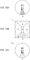
- the boom 9 enters the field of view of the upper camera 36 depending on the raising angle ⁇ 1 of the boom 9, and a missing part A6 in which a capturing region is blocked is generated in the upper image of the crane 1. Therefore, the missing part A6, blocked by the boom 9 according to the raising angle ⁇ 1 of the boom 9, in the capturing region of the upper camera 36 is registered for each raising angle ⁇ 1 of the boom 9 in the image processing device 38 of the image system 31.
- the image processing device 38 specifies a region having a shape corresponding to the missing part A6 in the upper image from the raising angle ⁇ 1 of the boom 9. Further, the image processing device 38 specifies a position corresponding to the missing part A6 in the upper image from the turning angle ⁇ 2 of the rotating base 7 in the bird's-eye-view image P1. Then, the image processing device 38 cuts out the specified position in the region having the specified shape from the bird's-eye-view image P1 and generates the cut-out as a supplementary image P4.
- the image processing device 38 generates a composite image P5 in which the supplementary image P4 is superimposed on the upper image of the crane 1. That is, the image processing device 38 generates the composite image P5 based on the upper image of the crane 1.
- the missing part in the upper image is compensated by the image that is being actually captured by the composition of the supplementary image P4 and the bird's-eye-view image P1 in the image system 31.
- the vehicle body cameras are provided at the front end portion, the rear end portion, and the left and right side surfaces of the vehicle 2 in the crane 1 in the present embodiment, but may be provided at a front end portion, a rear end portion, and left and right side surfaces of the rotating base 7.
- the image processing device 38 of the image system 31 determines the travel mode or the work mode of the crane 1 based on the raising angle ⁇ 1 of the boom 9, but may determine the travel mode or the work mode of the crane 1 based on a state that always occurs only in the work mode, such as an operating state of the outrigger 5 and the turning angle ⁇ 2 of the rotating base 7, or a control signal.
Landscapes
- Engineering & Computer Science (AREA)
- Multimedia (AREA)
- Signal Processing (AREA)
- Mechanical Engineering (AREA)
- Automation & Control Theory (AREA)
- Physics & Mathematics (AREA)
- General Physics & Mathematics (AREA)
- Theoretical Computer Science (AREA)
- Jib Cranes (AREA)
- Closed-Circuit Television Systems (AREA)
Abstract
Description
- The present invention relates to an image system and a work vehicle including the image system.
- Conventionally, in a mobile crane that is a work vehicle including a rotating base and a boom, a field of view of an operator from an operator's seat is sometimes blocked by the boom or the like stored in a vehicle during traveling and a blind spot occurs. In addition, the operator's seat provided to the rotating base turns together with the rotating base during work and, thus, a position and a range of the blind spot from the operator's seat change. For this reason, there is a case where visual recognition from a driver's seat is not easy even if a position of a rearview mirror or the like is improved. In this regard, there is known a bird's-eye-view image system that generates a bird's-eye-view image of the vicinity of a work vehicle to project a range which is to be a blind spot from an operator's seat, thereby indirectly expanding a field of view from the operator's seat. An example thereof is disclosed in
Patent Literature 1. - A bird's-eye-view image system described in
Patent Literature 1 includes: a plurality of cameras that acquire vicinity images of a work vehicle in which a rotating base capable of turning is provided to a traveling body; a display unit that displays a bird's-eye-view image based on the images acquired by the respective cameras; and a control unit that converts the images acquired by the respective cameras into images looking downward from an overhead virtual viewpoint, connects the converted images to generate the bird's-eye-view image, and displays the bird's-eye-view image on the display unit. In the bird's-eye-view image system, the plurality of cameras are provided in each of the traveling body and the rotating base. The bird's-eye-view image system can obtain an appropriate bird's-eye-view image by switching cameras used in the time of traveling and the time of working. - The bird's-eye-view image system configured in this manner can obtain a field of view as if a camera is provided above, by generating the bird's-eye-view image looking downward from the overhead virtual viewpoint. In the bird's-eye-view image system, however, the near vicinity of the traveling body, a part of the traveling body, and the rotating base are not included in capturing ranges of the cameras because the bird's-eye-view image is generated by the cameras provided to the traveling body or the rotating base. That is, blind spots are generated in a part of the traveling body, a turning body itself, and the near vicinity of a traveling vehicle in the bird's-eye-view image system, so that it is necessary for an operator to perform visual recognition with naked eyes.
- Patent Literature 1:
JP 2018-95449 A - An object of the present invention is to provide an image system that makes it possible to generate an image of a range extending over the entire circumference of a work vehicle and including the entire work vehicle and the near vicinity thereof from an image that is being actually captured, and a work vehicle provided with the image system.
- A problem to be solved by the present invention is as described above, and a means for solving the problem will be described below.
- That is, the present invention includes: an image processing device that is connected to an image capturing device to be capable of communicating with each other, the image capturing device being provided in a traveling body of a work vehicle having a boom, and that generates a composite image, based on a plurality of vicinity images obtained by the image capturing device capturing a vicinity of the traveling body without discontinuity over the entire circumference and on an upper image obtained by the image capturing device capturing the traveling body and the vicinity of the traveling body from above; and a display device that displays the composite image. The image processing device converts the plurality of vicinity images into images looking downward from an overhead virtual viewpoint and connects the converted images to generate a bird's-eye-view image, and generates the composite image by superimposing a part of one of the bird's-eye-view image and the upper image, which corresponds to a missing part in the other of the bird's-eye-view image and the upper image, on the missing part.
- The present invention has the following effects.
- In the present invention, the upper image of the work vehicle and the bird's-eye-view image of the vicinity of the work vehicle are combined, so that the missing part in the upper image or the bird's-eye-view image is compensated by the image that is being actually captured. As a result, it is possible to generate the image of the range extending over the entire circumference of the work vehicle and including the entire work vehicle and the near vicinity thereof from the image that is being actually captured.
-
-
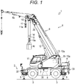
Fig. 1 is a side view illustrating an overall configuration of a crane. -
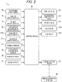
Fig. 2 is a block diagram illustrating a control configuration of the crane. -
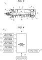
Fig. 3 is a plan view illustrating a schematic configuration of the crane. -
Fig. 4 is a block diagram illustrating a configuration of an image system. -
Fig. 5 is a schematic view illustrating raising and lowering of a boom in a travel mode and a work mode of the crane. -
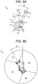
Figs. 6A and 6B illustrate images captured by a vehicle body camera and an upper camera.Fig. 6A illustrates a bird's-eye-view image generated from a vicinity image captured by the vehicle body camera, andFig. 6B illustrates a supplementary image generated from an upper image captured by the upper camera. -
Fig. 7 is a view illustrating a composite image in which the bird's-eye-view image and the supplementary image are superimposed on each other. -
Figs. 8A and 8B illustrate a relationship between turning of a rotating base in the crane and a display mode of the bird's-eye-view image.Fig. 8A illustrates a turning state of the rotating base of the crane, andFig. 8B illustrates the composite image rotated and displayed. -
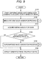
Fig. 9 is a flowchart illustrating a mode of image processing control in the image system. -
Fig. 10 is a flowchart illustrating a bird's-eye-view image generation process in the image system. -
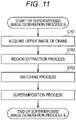
Fig. 11 is a flowchart illustrating a superimposed image generation process in the image system. -
Figs. 12A to 12C illustrate another embodiment of the superimposed image generation process.Fig. 12A illustrates a missing part in an upper image of a crane,Fig. 12B illustrates a supplementary image corresponding to the missing part in a bird's-eye-view image, andFig. 12C illustrates a composite image in which the supplementary image is superimposed on the missing part in the upper image. - Hereinafter, a
crane 1, which is an embodiment of a work vehicle according to the present invention, will be described with reference toFigs. 1 and2 . Note that a rough terrain crane will be described in the present embodiment, but any work vehicle having a boom, such as an all-terrain crane, a truck crane, a loading truck crane, and a high-place work vehicle, may be used. - As illustrated in
Fig. 1 , thecrane 1 is the mobile crane that can move to an unspecified place. Thecrane 1 includes a remote operation terminal 39 (seeFig. 2 ) capable of remotely operating avehicle 2 which is a traveling body, acrane device 6 which is a work device, acontrol device 30, and acrane device 6. In addition, thecrane 1 includes an image system 31 (seeFig. 2 ). - The
vehicle 2 is a moving body that carries thecrane device 6. Thevehicle 2 has a plurality ofwheels 3 and travels with anengine 4 as a power source. Thevehicle 2 is provided with anoutrigger 5. Thevehicle 2 can expand an operable range of thecrane 1 by extending theoutrigger 5 in the width direction of thevehicle 2 and grounding the jack cylinder. - The
crane device 6 is a device that lifts a load W with a wire rope. Thecrane device 6 includes a rotatingbase 7, a turninghydraulic motor 8, aboom 9, amain hook block 10, asub hook block 11, a raisinghydraulic cylinder 12, a main winch 13, a main hydraulic motor 13a, amain wire rope 14, a sub winch 15, a sub hydraulic motor 15a, asub wire rope 16, acabin 17, and the like. - The rotating
base 7 is a device that turns thecrane device 6. The rotatingbase 7 is configured to be rotatable about a center of the annular bearing as a center of rotation. The rotatingbase 7 is provided with a turninghydraulic motor 8 which is an actuator. The rotatingbase 7 is configured to be capable of turning in one direction and the other direction by the turninghydraulic motor 8. - The turning
hydraulic motor 8 is rotationally operated by a turning valve 23 (seeFig. 2 ) which is an electromagnetic proportional switching valve. The turningvalve 23 can control a flow rate of the hydraulic oil supplied to the turninghydraulic motor 8 to an arbitrary flow rate. The rotatingbase 7 is provided with a turning sensor 27 (seeFig. 2 ) that detects a turning angle θ2, which is a turning angle of therotating base 7, from a reference position. - The
boom 9 is a beam member that supports the wire rope to a state of being capable of lifting the load W. Theboom 9 is provided such that a proximal end of a base boom member is swingable substantially at the center of therotating base 7. Theboom 9 is configured to be freely elongated/contracted in the axial direction by moving each boom member by an elongation/contraction hydraulic cylinder (not illustrated) which is an actuator. In addition, theboom 9 is provided with ajib 9a. - A suspended
load camera 9b (seeFig. 2 ) is an image capturing device that captures images of the load W and features in the vicinity of the load W. The suspendedload camera 9b is provided at a distal end portion of theboom 9. The suspendedload camera 9b is configured to be capable of capturing images of the load W and features or terrain in the vicinity of thecrane 1 from vertically above the load W. - The elongation/contraction hydraulic cylinder is operated to be elongated/contracted by an elongation/contraction valve 24 (see
Fig. 2 ) which is an electromagnetic proportional switching valve. Theboom 9 is provided with an elongation/contraction sensor 28 that detects the length of theboom 9, a weight sensor that detects the weight of the load W, and the like. - The
main hook block 10 and thesub hook block 11 are members for suspending the load W. Themain hook block 10 is provided with a plurality of hook sheaves around which themain wire rope 14 is wound, and amain hook 10a for suspending the load W. Thesub hook block 11 is provided with a sub hook 11a for suspending the load W. - The raising
hydraulic cylinder 12 is an actuator that raises and lowers theboom 9 and holds an attitude of theboom 9. The raisinghydraulic cylinder 12 is operated to be elongated/contracted by a raising valve 25 (seeFig. 2 ) which is an electromagnetic proportional switching valve. Theboom 9 is provided with a raising sensor 29 (seeFig. 2 ) that detects a raising angle θ1 of theboom 9. - The main winch 13 and the sub winch 15 wind up (reel up) and feed out (release) the
main wire rope 14 and thesub wire rope 16. The main winch 13 is configured such that a main drum around which themain wire rope 14 is wound is rotated by a main hydraulic motor 13a, which is an actuator, and the sub winch 15 is configured such that a sub drum around which thesub wire rope 16 is wound is rotated by a sub hydraulic motor 15a which is an actuator. - The main hydraulic motor 13a is rotationally operated by a
main valve 26m (seeFig. 2 ) which is an electromagnetic proportional switching valve. The main winch 13 is configured such that the main hydraulic motor 13a is controlled by themain valve 26m and can be operated at an arbitrary winding-up and feeding-out speed. Similarly, the sub winch 15 is configured such that the sub hydraulic motor 15a is controlled by asub valve 26s (seeFig. 2 ), which is an electromagnetic proportional switching valve, and can be operated at an arbitrary winding-up and feeding-out speed. - The
cabin 17 is mounted on the rotatingbase 7. An operator's seat (not illustrated) is provided. The operator's seat is provided with an operation tool for operating thevehicle 2 to travel and aturning operation tool 18 for operating thecrane device 6, a raisingoperation tool 19, an elongation/contraction operation tool 20, a maindrum operation tool 21m, a subdrum operation tool 21s, and the like. - As illustrated in
Fig. 2 , acommunication device 22 is a device that receives a control signal from theremote operation terminal 39 via a wide-area information communication network or the like, and transmits control information or the like from thecrane device 6 via the wide-area information communication network or the like. Thecommunication device 22 is provided in thecabin 17. Thecommunication device 22 is configured to transfer the control signal or the like received from theremote operation terminal 39 to thecontrol device 30 of thecrane 1. - The
control device 30 is a device that controls the actuators of thecrane 1 via each operation valve. Thecontrol device 30 is provided in thecabin 17. In practice, thecontrol device 30 may be configured such that a CPU, a ROM, a RAM, an HDD, and the like are connected via a bus, or may be configured using a one-chip LSI or the like. Thecontrol device 30 stores various programs and data in order to control the operations of the respective actuators, switching valves, sensors, and the like. - The
control device 30 is connected to the suspendedload camera 9b, the turningoperation tool 18, the raisingoperation tool 19, the elongation/contraction operation tool 20, the maindrum operation tool 21m, and the subdrum operation tool 21s, and can acquire a video of the suspendedload camera 9b and acquire an operation amount of each of theturning operation tool 18, the raisingoperation tool 19, the maindrum operation tool 21m, and the subdrum operation tool 21s. - The
control device 30 is connected to thecommunication device 22, acquires the control signal from theremote operation terminal 39, and can transmit the control information from thecrane device 6, the video from the suspendedload camera 9b, and the like. - The
control device 30 is connected to the turningvalve 23, the elongation/contraction valve 24, the raisingvalve 25, themain valve 26m, and thesub valve 26s, and can transfer a control signal to the turningvalve 23, the raisingvalve 25, themain valve 26m, and thesub valve 26s. - The
control device 30 is connected to the turningsensor 27, the elongation/contraction sensor 28, and the raisingsensor 29, and can acquire attitude information such as the turning angle θ2 of therotating base 7, the boom length, and the raising angle θ1, and the weight of the load W. - The
control device 30 can generate a control signal corresponding to each operation tool based on the operation amount of each of theturning operation tool 18, the raisingoperation tool 19, the elongation/contraction operation tool 20, the maindrum operation tool 21m, and the subdrum operation tool 21s. - The
image system 31 is a system that combines a vicinity image and an upper image of thecrane 1 to generate an image of a range extending over the entire circumference of thecrane 1. Theimage system 31 is provided in thecabin 17 of thecrane 1 and is connected to thecontrol device 30. - The
image system 31 is connected to thecontrol device 30, and can acquire the turning angle θ2 of therotating base 7 and the raising angle θ1 of theboom 9 from thecontrol device 30. In addition, theimage system 31 can acquire an operation signal for grounding the jack cylinder of theoutrigger 5 from thecontrol device 30. - The
crane 1 configured in this manner can move thecrane device 6 to an arbitrary position by causing thevehicle 2 to travel. In addition, thecrane 1 can increase a lifting height and an operating radius of thecrane device 6 by raising theboom 9 at an arbitrary raising angle θ1 by the raisinghydraulic cylinder 12 with the operation of the raisingoperation tool 19 and extending theboom 9 to an arbitrary boom length with the operation of the elongation/contraction operation tool 20. In addition, thecrane 1 can carry the load W by lifting the load W with the operation of the subdrum operation tool 21s and the like and rotating therotating base 7 by operating the turningoperation tool 18. - Next, the
image system 31 will be specifically described with reference toFigs. 3 and 4 . Theimage system 31 is a system that combines a bird's-eye-view image P1 in the vicinity of thecrane 1 and a supplementary image P2 extracted from an upper image to generate a composite image P3 in a range extending over the entire circumference of thecrane 1 including thecrane 1. The image in the range extending over the entire circumference of thecrane 1 is an image including thevehicle 2 of thecrane 1 and the ground (traveling surface) and features surrounding thevehicle 2 when viewed from the upper side (above) in the vertical direction of thecrane 1, and is an image including the ground and features in a region from a position adjacent to thevehicle 2 to a position at a predetermined distance around the vehicle 2 (seeFigs. 6A and 6B ) . - As illustrated in
Figs. 3 and 4 , theimage system 31 includes a vehiclebody front camera 32, a vehicle bodyrear camera 33, a vehicle bodyright camera 34, and a vehicle body leftcamera 35, which are vehicle body cameras provided in thevehicle 2, anupper camera 36 provided in theboom 9, adisplay device 37, and animage processing device 38. Note that the vehiclebody front camera 32, the vehicle bodyrear camera 33, the vehicle bodyright camera 34, the vehicle body leftcamera 35, and theupper camera 36 correspond to the "image capturing device" of the present invention, and are connected to theimage processing device 38 to be capable of communicating with each other. - The vehicle
body front camera 32, the vehicle bodyrear camera 33, the vehicle bodyright camera 34, and the vehicle body leftcamera 35 are configured using wide-angle cameras each of which has an angle of view of approximately 180 degrees, for example. The vehiclebody front camera 32 is provided at a front end portion which is an end portion on a side in the forward direction of thevehicle 2. The vehiclebody front camera 32 captures an image of the front of thevehicle 2. The vehicle bodyrear camera 33 is provided at a rear end portion which is an end portion on a side in the reverse direction of thevehicle 2. The vehicle bodyrear camera 33 captures an image of the rear of thevehicle 2. The vehicle bodyright camera 34 is provided on a right side surface in the traveling direction of thevehicle 2. The vehicle bodyright camera 34 captures an image of the right of thevehicle 2. The vehicle body leftcamera 35 is provided on a left side surface in the traveling direction of thevehicle 2. The vehicle body leftcamera 35 captures an image of the left of thevehicle 2. Note that each of the vehicle body cameras may be provided at a position where an image of the vicinity of thevehicle 2 can be acquired without discontinuity over the entire circumference. - The
upper camera 36 is configured using, for example, a wide-angle camera which has an angle of view of approximately 180 degrees. Theupper camera 36 is provided at a distal end portion of a base boom member swingably supported by the rotatingbase 7 in the boom 9 (seeFig. 1 ). Theupper camera 36 acquires an upper image of thecrane 1, which is an image including thevehicle 2 and the vicinity of thevehicle 2 captured from above thevehicle 2, in a raised state of theboom 9. Note that theupper camera 36 is provided to the base boom member in the present embodiment, but may be provided in a part where the upper image of thecrane 1, which is the image including thevehicle 2 and the vicinity of thevehicle 2 captured from above thevehicle 2, can be acquired. - The
display device 37 is a device that displays the images of the vehicle body cameras and theupper camera 36. Thedisplay device 37 is disposed inside thecabin 17. Note that thedisplay device 37 may be provided in theremote operation terminal 39 that remotely operates thecrane 1 outside thecabin 17. - The
image processing device 38 is a processing device that converts and combines vicinity images of thecrane 1 captured by the respective vehicle body cameras and the upper image of thecrane 1 captured by theupper camera 36. Theimage processing device 38 is provided inside thecabin 17. In practice, theimage processing device 38 may be configured such that a CPU, a ROM, a RAM, an HDD, and the like are connected via a bus, or may be configured using a one-chip LSI or the like. Theimage processing device 38 stores various programs and data configured to control the respective vehicle body cameras, theupper camera 36, and the respective sensors, acquire images and signals from the sensors, and perform image processing. - The
image processing device 38 is connected to the vehiclebody front camera 32, the vehicle bodyrear camera 33, the vehicle bodyright camera 34, the vehicle body leftcamera 35, and theupper camera 36, and can acquire the vicinity images of thecrane 1 captured by the vehiclebody front camera 32, the vehicle bodyrear camera 33, the vehicle bodyright camera 34, and the vehicle body leftcamera 35 and the upper image of thecrane 1 captured by theupper camera 36. In addition, theimage processing device 38 is connected to thedisplay device 37, and can transmit generated images to thedisplay device 37. - The
image processing device 38 performs control of a process of generating the bird's-eye-view image P1 (image data thereof) based on signals from the respective vehicle body cameras, the supplementary image P2 (image data thereof) based on a signal from theupper camera 36, and the composite image P3 (image data thereof) of the bird's-eye-view image P1 and the supplementary image P2, a display process of displaying the composite image P3 on thedisplay device 37, an acquisition process of acquiring various types of acquired information, and the like. - The
image processing device 38 can perform a bird's-eye-view image generation process of generating the bird's-eye-view image P1 from the vicinity images of thecrane 1 captured by the vehiclebody front camera 32, the vehicle bodyrear camera 33, the vehicle bodyright camera 34, and the vehicle body leftcamera 35 every unit time (seeFig. 10 ). The bird's-eye-view image generation process includes, for example, a distortion correction process (step S121), a bird's-eye view conversion process (step S122), and an image combination process (step S123). Note that theimage processing device 38 may perform these processes simultaneously or perform processes of other contents as long as the bird's-eye-view image P1 is generated, - As the distortion correction process, the
image processing device 38 multiplies a coordinate value of an input pixel of an image captured by each of the vehicle body cameras by a coefficient based on a lens distortion coefficient, an aspect ratio, or the like to convert the coordinate value into a coordinate value of an output pixel, thereby correcting distortion due to a lens. - As the bird's-eye view conversion process, the
image processing device 38 multiplies coordinate values of appropriately selected input pixels by various coefficients based on a camera attachment angle or the like to form all of coordinate values of output pixels, thereby converting the image into a captured image (individual bird's-eye-view image) looking downward from a virtual viewpoint set above thecrane 1. - As the image combination process, the
image processing device 38 connects adjacent individual bird's-eye-view images from the respective vehicle body cameras, which have been subjected to the above-described processes, as one image while eliminating a sense of incompatibility at a joint by performing linear interpolation or the like on the brightness of the corresponding coordinate value, thereby generating the bird's-eye-view image P1. - The
image processing device 38 can perform a superimposed image generation process of generating the supplementary image P2 that is an image of a part, which corresponds to a missing part in the bird's-eye-view image P1, in the upper image of thecrane 1 captured by theupper camera 36, and generating the composite image P3 in which the supplementary image P2 is superimposed on the missing part in the bird's-eye-view image P1 every unit time (seeFig. 11 ). The superimposed image generation process includes, for example, a region extraction process (step S152), a matching process (step S153), and a superimposition process (step S154). Note that theimage processing device 38 may perform these processes simultaneously or perform processes of other contents as long as the composite image P3 is generated, Note that the missing part in the bird's-eye-view image P1 is a part corresponding to images of thevehicle 2 and therotating base 7 of thecrane 1 that are not included in the field of view of each of the vehicle body cameras. - As the region extraction process, the image processing device extracts a closed region by a known method, such as binarization, from the upper image of the
crane 1 captured by theupper camera 36. - As the matching process, the
image processing device 38 slides a reference image on the upper image using an image of thevehicle 2 registered in advance as the reference image, and compares the region extracted from the upper image with the reference image. Theimage processing device 38 specifies a region having high similarity with the reference image as the supplementary image P2 corresponding to thevehicle 2. - As the superimposition process, the
image processing device 38 cuts out the specified supplementary image P2, and corrects distortion by multiplying the specified supplementary image P2 by a coefficient based on a lens distortion coefficient, an aspect ratio, or the like so as to conform to the missing part in the bird's-eye-view image P1. Further, theimage processing device 38 generates the composite image P3 in a state in which the corrected supplementary image P2 is superimposed on the bird's-eye-view image P1. - The
image system 31 configured in this manner can generate the bird's-eye-view image P1 every unit time from the vicinity images of thecrane 1 captured by the vehiclebody front camera 32, the vehicle bodyrear camera 33, the vehicle bodyright camera 34, and the vehicle body leftcamera 35 which are the vehicle body cameras. In addition, theimage system 31 can generate the supplementary image P2, which is the image of the part corresponding to the missing part in the bird's-eye-view image P1, every unit time from the upper image of thecrane 1 captured by theupper camera 36. Further, theimage system 31 can form the composite image P3 in which the supplementary image P2 is superimposed on the missing part in the bird's-eye-view image P1 generated from the image of the vicinity of avehicle body 2 every unit time. - Next, control of the
image system 31 in a travel mode in which thecrane 1 can travel and in a work mode of thecrane device 6 will be described with reference toFigs. 5 to 8 . In the present embodiment, the time of traveling of thecrane 1 refers to a state in which the use of theboom 9 is not practical and is lowered up to a reference angle α or less at which it is difficult to sufficiently secure the field of view of theupper camera 36. In addition, the work mode of thecrane 1 refers to a state in which theboom 9 is raised exceeding the reference angle α. - When the
crane 1 is activated, theimage processing device 38 of theimage system 31 starts capturing the surroundings of thecrane 1 by the vehiclebody front camera 32, the vehicle bodyrear camera 33, the vehicle bodyright camera 34, and the vehicle body leftcamera 35. - As illustrated in
Fig. 5 , theimage processing device 38 acquires the raising angle θ1 of theboom 9 from thecontrol device 30 of thecrane 1. When the raising angle θ1 of theboom 9 is equal to or smaller than the reference angle α, theimage processing device 38 determines that thecrane 1 is in the travel mode. On the other hand, when the raising angle θ1 of theboom 9 acquired from thecontrol device 30 of thecrane 1 is larger than the reference angle α, theimage processing device 38 determines that thecrane 1 is in the work mode. - As illustrated in
Fig. 6A , theimage processing device 38 performs the bird's-eye-view image generation process and generates the bird's-eye-view image P1 from the vicinity images of thecrane 1 captured by the respective vehicle body cameras every unit time. Theimage processing device 38 generates a front captured image (hereinafter, simply referred to as a "bird's-eye-view image") A1 looking downward from a virtual viewpoint set above thecrane 1 from the image captured by the vehiclebody front camera 32. Similarly, theimage processing device 38 generates a rear bird's-eye-view image A2 from the image captured by the vehicle bodyrear camera 33, generates a right bird's-eye-view image A3 from the image captured by the vehicle bodyright camera 34, and generates a left bird's-eye-view image A4 from the image captured by the vehicle body leftcamera 35. Theimage processing device 38 connects the front bird's-eye-view image A1, the rear bird's-eye-view image A2, the right bird's-eye-view image A3, and the left bird's-eye-view image A4 as one bird's-eye-view image to generate the bird's-eye-view image P1. At this time, a part of thecrane 1 corresponding to thevehicle 2 is generated as a missing part A5 that is not capturable by the vehicle body camera. Note that a range surrounded by a circular ring inFigs. 7 ,8 , and12 is a range displayed on thedisplay device 37. - As illustrated in
Fig. 6B , when determining that thecrane 1 is in the work mode, theimage processing device 38 performs the superimposed image generation process and generates the supplementary image P2 that is a part, which corresponds to the missing part A5 of the bird's-eye-view image P1, in the upper image of thecrane 1 captured by theupper camera 36. - As illustrated in
Fig. 7 , theimage processing device 38 performs the superimposed image generation process and superimposes the supplementary image P2 on the missing part A5 of the bird's-eye-view image P1 to generate the composite image P3 based on the bird's-eye-view image P1 every unit time. - In addition, the
image processing device 38 acquires the turning angle θ2 of therotating base 7 from thecontrol device 30 of thecrane 1 as illustrated inFig. 8A . When therotating base 7 turns clockwise by an angle θ2 from the reference position, theimage processing device 38 acquires the turning angle θ2. - As illustrated in
Fig. 8B , theimage processing device 38 rotates the composite image P3 counterclockwise by the angle θ2 and displays the rotated composite image P3 on thedisplay device 37. That is, when the rotatingbase 7 has turned in one direction by an arbitrary angle, theimage processing device 38 causes the composite image P3 in which the missing part in the bird's-eye-view image P1 is compensated by the supplementary image P2 to be rotated in the other direction by the angle at which the rotatingbase 7 has turned and displayed. With such control, theimage system 31 displays the composite image P3 on thedisplay device 37 in conjunction with the turning of therotating base 7 using the rotatingbase 7 as the reference. As a result, the range extending over the entire circumference of thecrane 1 including theentire crane 1 and the near vicinity of thecrane 1 is displayed using the operator's seat as the reference, and thus, an operator can easily grasp a positional relationship between the vicinity of thecrane 1 and theboom 9. - Hereinafter, image processing control for generating the bird's-eye-view image P1, the supplementary image P2, and the composite image P3 by the
image system 31 will be specifically described with reference toFigs. 9 to 11 . In the following embodiment, thecrane 1 is operated by the operation tools provided in thecabin 17, but may be controlled by theremote operation terminal 39. - As illustrated in
Fig. 9 , theimage processing device 38 starts capturing by the vehiclebody front camera 32, the vehicle bodyrear camera 33, the vehicle bodyright camera 34, and the vehicle body leftcamera 35 and acquires the vicinity images of thecrane 1 in step S110 of the image processing control, and the step is shifted to step S120. - In step S120, the
image processing device 38 starts a bird's-eye-view image generation process A, and the step is shifted to step S121 (seeFig. 10 ). - As illustrated in
Fig. 10 , theimage processing device 38 corrects distortion due to the lens in the acquired images as the distortion correction process in step S121 in the bird's-eye-view image generation process A, and the step is shifted to step S122. - In step S122, the
image processing device 38 converts the acquired vicinity images of thecrane 1 into the front bird's-eye-view image A1, the rear bird's-eye-view image A2, the right bird's-eye-view image A3, and the left bird's-eye-view image A4 as the bird's-eye view conversion process, and the step is shifted to step S123. - In step S123, the
image processing device 38 connects adjacent individual bird's-eye-view images captured from the vehicle body cameras, which have been subjected to the respective processes, as one image to generate the bird's-eye-view image P1 as the image combination process, and ends the bird's-eye-view image generation process A, and the step is shifted to step S130 (seeFig. 9 ). - As illustrated in
Fig. 9 , in step S130, theimage processing device 38 acquires the raising angle θ1 of theboom 9 from thecontrol device 30 of thecrane 1, and the step is shifted to step S140. - In step S140, the
image processing device 38 determines whether the acquired raising angle θ1 of theboom 9 is larger than the reference angle α. As a result, when the raising angle θ1 of theboom 9 is larger than the reference angle α, that is, when thecrane 1 is in the work mode, theimage processing device 38 shifts the step to step S150. On the other hand, when the raising angle θ1 of theboom 9 is equal to or smaller than the reference angle α, that is, when thecrane 1 is in the travel mode, theimage processing device 38 shifts the step to step S160. - In step S150, the
image processing device 38 starts a superimposed image generation process B, and the step is shifted to step S151 (seeFig. 11 ). - As illustrated in
Fig. 11 , theimage processing device 38 starts capturing by theupper camera 36 and acquires the upper image of thecrane 1 in step S151 in the superimposed image generation process B, and the step is shifted to step S152. - In step S152, the
image processing device 38 extracts a closed region from the upper image of thecrane 1 by a known method such as binarization as the region extraction process, and the step is shifted to step S153. - In step S153, the
image processing device 38 compares the region extracted from the upper image of thecrane 1 with the reference image, specifies a region having high similarity as the supplementary image P2 corresponding to thevehicle 2 as the matching process, and the step is shifted to step 154. - In step S154, the
image processing device 38 cuts out and corrects the supplementary image P2 to conform to a missing part in the bird's-eye-view image P1 and superimposes the supplementary image P2 on the bird's-eye-view image P1 to generate the composite image P3 based on the bird's-eye-view image P1 as the superimposition process, and ends the superimposed image generation process B, and the step is shifted to step S160 (seeFig. 9 ). - As illustrated in
Fig. 9 , theimage processing device 38 displays the generated image on thedisplay device 37 in step S160, and the step is shifted to step S110. - With this configuration, the
image processing device 38 of theimage system 31 determines whether thecrane 1 is in the travel mode or the work mode based on the raising angle θ1 of theboom 9. For this reason, theimage system 31 constantly captures the upper image of thecrane 1 as long as theupper camera 36 can capture the upper image of thecrane 1. That is, in an image processing system, the range extending over the entire circumference of thecrane 1 is captured by a camera suitable for capturing in accordance with a state of thecrane 1. Theimage system 31 generates the bird's-eye-view image P1 in the travel mode, and generates the composite image P3 based on the bird's-eye-view image P1 in the work mode. Since the composite image P3 is obtained by superimposing the supplementary image P2 of thevehicle 2 captured by theupper camera 36, a part that is not capturable by the vehicle body camera is supplemented. Therefore, the composite image P3 of the image system is displayed in real time even when a worker or the like moves up on thevehicle 2 during work. As a result, it is possible to generate an image of the range extending over the entire circumference of thecrane 1 including thecrane 1 and the near vicinity of thecrane 1 from an image that is being actually captured. - Note that the supplementary image P2 is superimposed on the missing part in the bird's-eye-view image P1 generated based on the vicinity image of the
crane 1 captured by the vehicle body camera in the composite image P3 in the present embodiment. However, a corresponding part of the bird's-eye-view image P1 may be superimposed and displayed on a missing part in the upper image of thecrane 1 captured by theupper camera 36. - As illustrated in
Fig. 12A , theboom 9 enters the field of view of theupper camera 36 depending on the raising angle θ1 of theboom 9, and a missing part A6 in which a capturing region is blocked is generated in the upper image of thecrane 1. Therefore, the missing part A6, blocked by theboom 9 according to the raising angle θ1 of theboom 9, in the capturing region of theupper camera 36 is registered for each raising angle θ1 of theboom 9 in theimage processing device 38 of theimage system 31. - As illustrated in
Fig. 12B , theimage processing device 38 specifies a region having a shape corresponding to the missing part A6 in the upper image from the raising angle θ1 of theboom 9. Further, theimage processing device 38 specifies a position corresponding to the missing part A6 in the upper image from the turning angle θ2 of therotating base 7 in the bird's-eye-view image P1. Then, theimage processing device 38 cuts out the specified position in the region having the specified shape from the bird's-eye-view image P1 and generates the cut-out as a supplementary image P4. - As illustrated in
Fig. 12C , theimage processing device 38 generates a composite image P5 in which the supplementary image P4 is superimposed on the upper image of thecrane 1. That is, theimage processing device 38 generates the composite image P5 based on the upper image of thecrane 1. With this configuration, the missing part in the upper image is compensated by the image that is being actually captured by the composition of the supplementary image P4 and the bird's-eye-view image P1 in theimage system 31. As a result, it is possible to generate an image of the range extending over the entire circumference of thecrane 1 including theentire crane 1 and the near vicinity of thecrane 1 from the image that is being actually captured. - Note that the vehicle body cameras are provided at the front end portion, the rear end portion, and the left and right side surfaces of the
vehicle 2 in thecrane 1 in the present embodiment, but may be provided at a front end portion, a rear end portion, and left and right side surfaces of therotating base 7. In addition, theimage processing device 38 of theimage system 31 determines the travel mode or the work mode of thecrane 1 based on the raising angle θ1 of theboom 9, but may determine the travel mode or the work mode of thecrane 1 based on a state that always occurs only in the work mode, such as an operating state of theoutrigger 5 and the turning angle θ2 of therotating base 7, or a control signal. - The above-described embodiment merely illustrates a typical form, and various modifications can be implemented within a scope not departing from a gist of the embodiment. Needless to say, the present invention can be implemented in various forms, and the scope of the present invention encompasses those illustrated in the description of the claims, those having meanings equivalent to those in the claims, and all alterations within the scope.
- The disclosure content of the description, drawings, and abstract included in the
Japanese Patent Application No. 2019-114943 filed on June 20, 2019 -
- 1
- crane
- 6
- crane device
- 9
- boom
- 30
- control device
- 31
- image system
- 32
- vehicle body front camera
- 33
- vehicle body rear camera
- 34
- vehicle body right camera
- 35
- vehicle body left camera
- 36
- upper camera
- 37
- display device
- P1
- bird's-eye-view image
- P2
- supplementary image
- P3
- composite image
Claims (11)
- An image system comprising:an image processing device that is connected to an image capturing device to be capable of communicating with each other, the image capturing device being provided in a traveling body of a work vehicle having a boom, and that generates a composite image, based on a plurality of vicinity images obtained by the image capturing device capturing a vicinity of the traveling body without discontinuity over an entire circumference and on an upper image obtained by the image capturing device capturing the traveling body and the vicinity of the traveling body from above; anda display device that displays the composite image, whereinthe image processing deviceconverts the plurality of vicinity images into images looking downward from an overhead virtual viewpoint and connects the converted images to generate a bird's-eye-view image, andgenerates the composite image by superimposing a part of one of the bird's-eye-view image and the upper image, which corresponds to a missing part in the other of the bird's-eye-view image and the upper image, on the missing part.
- The image system according to claim 1, wherein
the image processing device superimposes a part of the upper image, which corresponds to a missing part in the bird's-eye-view image, on the missing part. - The image system according to claim 1, wherein
the image processing device superimposes a part of the bird's-eye-view image, which corresponds to a missing part in the upper image, on the missing part. - The image system according to any one of claims 1 to 3, whereinthe traveling body is provided with the boom with a rotating base interposed between the traveling body and the boom, andwhen the rotating base has turned in one direction, the image processing device rotates the composite image being displayed on the display device in another direction by an angle at which the rotating base has turned.
- The image system according to any one of claims 1 to 4, whereinthe boom is raisable and lowerable, andthe image processing devicestarts to generate the composite image when a raising angle of the boom exceeds a reference angle during generation of the bird's-eye-view image.
- The image system according to any one of claims 1 to 5, whereinthe image processing devicegenerates the bird's-eye-view image when the work vehicle is in a travel mode, and generates the composite image when the work vehicle is in a work mode.
- The image system according to any one of claims 1 to 6, wherein
the image capturing device includes a plurality of vehicle body cameras that capture the plurality of vicinity images and an upper camera that captures the upper image. - The image system according to any one of claims 1 to 7, wherein
the image processing device is provided in a cabin mounted on the rotating base. - The image system according to any one of claims 1 to 8, wherein
the display device is disposed inside a cabin mounted on the rotating base. - The image system according to any one of claims 1 to 8, wherein
the display device is provided in a remote operation terminal that remotely operates the work vehicle outside a cabin mounted on the rotating base. - A work vehicle comprising the image system according to any one of claims 1 to 9.
Applications Claiming Priority (2)
| Application Number | Priority Date | Filing Date | Title |
|---|---|---|---|
| JP2019114943 | 2019-06-20 | ||
| PCT/JP2020/024136 WO2020256101A1 (en) | 2019-06-20 | 2020-06-19 | Image system and work vehicle provided with image system |
Publications (3)
| Publication Number | Publication Date |
|---|---|
| EP3988491A1 true EP3988491A1 (en) | 2022-04-27 |
| EP3988491A4 EP3988491A4 (en) | 2023-08-02 |
| EP3988491B1 EP3988491B1 (en) | 2025-11-05 |
Family
ID=74040508
Family Applications (1)
| Application Number | Title | Priority Date | Filing Date |
|---|---|---|---|
| EP20826038.0A Active EP3988491B1 (en) | 2019-06-20 | 2020-06-19 | Image system and work vehicle provided with image system |
Country Status (4)
| Country | Link |
|---|---|
| US (1) | US12187584B2 (en) |
| EP (1) | EP3988491B1 (en) |
| JP (1) | JPWO2020256101A1 (en) |
| WO (1) | WO2020256101A1 (en) |
Families Citing this family (1)
| Publication number | Priority date | Publication date | Assignee | Title |
|---|---|---|---|---|
| JP2025000438A (en) * | 2023-06-19 | 2025-01-07 | 株式会社タダノ | Crane device |
Family Cites Families (15)
| Publication number | Priority date | Publication date | Assignee | Title |
|---|---|---|---|---|
| JP5462008B2 (en) * | 2010-01-25 | 2014-04-02 | 株式会社タダノ | Image display system |
| JP5269026B2 (en) * | 2010-09-29 | 2013-08-21 | 日立建機株式会社 | Work machine ambient monitoring device |
| JP6080450B2 (en) * | 2012-09-21 | 2017-02-15 | 株式会社タダノ | Surveillance camera device |
| JP6321977B2 (en) | 2014-01-23 | 2018-05-09 | クラリオン株式会社 | Perimeter monitoring equipment for heavy machinery |
| US10781572B2 (en) * | 2015-03-31 | 2020-09-22 | Komatsu Ltd. | Working machine |
| JP6756554B2 (en) * | 2016-09-09 | 2020-09-16 | 株式会社タダノ | Image display system |
| JP6756555B2 (en) * | 2016-09-09 | 2020-09-16 | 株式会社タダノ | Bird's-eye view image system, bird's-eye view image display method and program |
| WO2018110707A1 (en) | 2016-12-15 | 2018-06-21 | 株式会社タダノ | Remote operation terminal and work vehicle provided with remote operation terminal |
| JP6743676B2 (en) * | 2016-12-15 | 2020-08-19 | 株式会社タダノ | Remote control terminal |
| CN110114244B (en) * | 2017-02-17 | 2023-07-04 | 住友重机械工业株式会社 | Peripheral monitoring system for machine tools |
| US10919584B2 (en) * | 2017-10-17 | 2021-02-16 | Tadano Ltd. | Work vehicle |
| JP6958216B2 (en) * | 2017-10-17 | 2021-11-02 | 株式会社タダノ | Work vehicle |
| JP7049826B2 (en) | 2017-12-25 | 2022-04-07 | 株式会社メガチップス | Transmission circuit and control method of the transmission circuit |
| JP7095287B2 (en) * | 2018-01-22 | 2022-07-05 | コベルコ建機株式会社 | Swivel hydraulic work machine |
| JP7151532B2 (en) * | 2019-02-14 | 2022-10-12 | 株式会社タダノ | Crane and crane path generation system |
-
2020
- 2020-06-19 US US17/615,756 patent/US12187584B2/en active Active
- 2020-06-19 WO PCT/JP2020/024136 patent/WO2020256101A1/en not_active Ceased
- 2020-06-19 EP EP20826038.0A patent/EP3988491B1/en active Active
- 2020-06-19 JP JP2021526916A patent/JPWO2020256101A1/ja active Pending
Also Published As
| Publication number | Publication date |
|---|---|
| JPWO2020256101A1 (en) | 2020-12-24 |
| EP3988491A4 (en) | 2023-08-02 |
| US12187584B2 (en) | 2025-01-07 |
| US20220315391A1 (en) | 2022-10-06 |
| EP3988491B1 (en) | 2025-11-05 |
| WO2020256101A1 (en) | 2020-12-24 |
Similar Documents
| Publication | Publication Date | Title |
|---|---|---|
| US11292699B2 (en) | Remote operation terminal and work vehicle provided with remote operation terminal | |
| JP5876679B2 (en) | Performance line display device | |
| JP5462008B2 (en) | Image display system | |
| US11407621B2 (en) | Crane | |
| JP7106929B2 (en) | work vehicle | |
| EP3556713A1 (en) | Remote operation terminal and work vehicle provided with remote operation terminal | |
| US12492103B2 (en) | Remote operation terminal and mobile crane comprising remote operation terminal | |
| US11926511B2 (en) | Remote operation terminal and mobile crane provided with remote operation terminal | |
| JP7172199B2 (en) | Remote control terminal and work vehicle | |
| US11905145B2 (en) | Remote control terminal and work vehicle | |
| US12066823B2 (en) | Remote control terminal, and working vehicle provided with remote control terminal | |
| US12172871B2 (en) | Crane information display system | |
| JP2018095375A (en) | Crane | |
| EP3988491B1 (en) | Image system and work vehicle provided with image system | |
| WO2014119711A1 (en) | Transport machine position adjustment system | |
| CN111052734B (en) | work vehicle | |
| WO2019172413A1 (en) | Crane | |
| EP4043967A1 (en) | Control system, and crane | |
| US11981548B2 (en) | Crane and path generation system | |
| JP7006442B2 (en) | crane | |
| EP3763656B1 (en) | Work vehicle | |
| JP2017061382A (en) | Radio communication system for work machine | |
| JP7167464B2 (en) | Remote control terminal and work vehicle equipped with remote control terminal | |
| WO2024262519A1 (en) | Crane device | |
| JP2019163122A (en) | Work vehicle and remote control terminal |
Legal Events
| Date | Code | Title | Description |
|---|---|---|---|
| STAA | Information on the status of an ep patent application or granted ep patent |
Free format text: STATUS: THE INTERNATIONAL PUBLICATION HAS BEEN MADE |
|
| PUAI | Public reference made under article 153(3) epc to a published international application that has entered the european phase |
Free format text: ORIGINAL CODE: 0009012 |
|
| STAA | Information on the status of an ep patent application or granted ep patent |
Free format text: STATUS: REQUEST FOR EXAMINATION WAS MADE |
|
| 17P | Request for examination filed |
Effective date: 20220113 |
|
| AK | Designated contracting states |
Kind code of ref document: A1 Designated state(s): AL AT BE BG CH CY CZ DE DK EE ES FI FR GB GR HR HU IE IS IT LI LT LU LV MC MK MT NL NO PL PT RO RS SE SI SK SM TR |
|
| DAV | Request for validation of the european patent (deleted) | ||
| DAX | Request for extension of the european patent (deleted) | ||
| A4 | Supplementary search report drawn up and despatched |
Effective date: 20230703 |
|
| RIC1 | Information provided on ipc code assigned before grant |
Ipc: G06T 3/00 20060101ALI20230627BHEP Ipc: G06T 1/00 20060101ALI20230627BHEP Ipc: B66C 13/00 20060101AFI20230627BHEP |
|
| STAA | Information on the status of an ep patent application or granted ep patent |
Free format text: STATUS: EXAMINATION IS IN PROGRESS |
|
| 17Q | First examination report despatched |
Effective date: 20240718 |
|
| REG | Reference to a national code |
Ref country code: DE Ref legal event code: R079 Free format text: PREVIOUS MAIN CLASS: B66C0013000000 Ipc: B66C0013460000 Ref country code: DE Ref legal event code: R079 Ref document number: 602020061780 Country of ref document: DE Free format text: PREVIOUS MAIN CLASS: B66C0013000000 Ipc: B66C0013460000 |
|
| GRAP | Despatch of communication of intention to grant a patent |
Free format text: ORIGINAL CODE: EPIDOSNIGR1 |
|
| STAA | Information on the status of an ep patent application or granted ep patent |
Free format text: STATUS: GRANT OF PATENT IS INTENDED |
|
| RIC1 | Information provided on ipc code assigned before grant |
Ipc: G06T 3/4038 20240101ALI20250507BHEP Ipc: B66C 23/88 20060101ALI20250507BHEP Ipc: B66C 13/46 20060101AFI20250507BHEP |
|
| INTG | Intention to grant announced |
Effective date: 20250527 |
|
| GRAS | Grant fee paid |
Free format text: ORIGINAL CODE: EPIDOSNIGR3 |
|
| GRAA | (expected) grant |
Free format text: ORIGINAL CODE: 0009210 |
|
| STAA | Information on the status of an ep patent application or granted ep patent |
Free format text: STATUS: THE PATENT HAS BEEN GRANTED |
|
| AK | Designated contracting states |
Kind code of ref document: B1 Designated state(s): AL AT BE BG CH CY CZ DE DK EE ES FI FR GB GR HR HU IE IS IT LI LT LU LV MC MK MT NL NO PL PT RO RS SE SI SK SM TR |
|
| REG | Reference to a national code |
Ref country code: CH Ref legal event code: F10 Free format text: ST27 STATUS EVENT CODE: U-0-0-F10-F00 (AS PROVIDED BY THE NATIONAL OFFICE) Effective date: 20251105 Ref country code: GB Ref legal event code: FG4D |
|
| REG | Reference to a national code |
Ref country code: DE Ref legal event code: R096 Ref document number: 602020061780 Country of ref document: DE |
|
| REG | Reference to a national code |
Ref country code: IE Ref legal event code: FG4D |
|
| REG | Reference to a national code |
Ref country code: NL Ref legal event code: MP Effective date: 20251105 |
|
| PG25 | Lapsed in a contracting state [announced via postgrant information from national office to epo] |
Ref country code: ES Free format text: LAPSE BECAUSE OF FAILURE TO SUBMIT A TRANSLATION OF THE DESCRIPTION OR TO PAY THE FEE WITHIN THE PRESCRIBED TIME-LIMIT Effective date: 20251105 |
|
| REG | Reference to a national code |
Ref country code: LT Ref legal event code: MG9D |
|
| PG25 | Lapsed in a contracting state [announced via postgrant information from national office to epo] |
Ref country code: NO Free format text: LAPSE BECAUSE OF FAILURE TO SUBMIT A TRANSLATION OF THE DESCRIPTION OR TO PAY THE FEE WITHIN THE PRESCRIBED TIME-LIMIT Effective date: 20260205 |
|
| PG25 | Lapsed in a contracting state [announced via postgrant information from national office to epo] |
Ref country code: HR Free format text: LAPSE BECAUSE OF FAILURE TO SUBMIT A TRANSLATION OF THE DESCRIPTION OR TO PAY THE FEE WITHIN THE PRESCRIBED TIME-LIMIT Effective date: 20251105 Ref country code: AT Free format text: LAPSE BECAUSE OF FAILURE TO SUBMIT A TRANSLATION OF THE DESCRIPTION OR TO PAY THE FEE WITHIN THE PRESCRIBED TIME-LIMIT Effective date: 20251105 Ref country code: FI Free format text: LAPSE BECAUSE OF FAILURE TO SUBMIT A TRANSLATION OF THE DESCRIPTION OR TO PAY THE FEE WITHIN THE PRESCRIBED TIME-LIMIT Effective date: 20251105 |
|
| REG | Reference to a national code |
Ref country code: AT Ref legal event code: MK05 Ref document number: 1854180 Country of ref document: AT Kind code of ref document: T Effective date: 20251105 |
|
| PG25 | Lapsed in a contracting state [announced via postgrant information from national office to epo] |
Ref country code: NL Free format text: LAPSE BECAUSE OF FAILURE TO SUBMIT A TRANSLATION OF THE DESCRIPTION OR TO PAY THE FEE WITHIN THE PRESCRIBED TIME-LIMIT Effective date: 20251105 |
|
| PG25 | Lapsed in a contracting state [announced via postgrant information from national office to epo] |
Ref country code: RS Free format text: LAPSE BECAUSE OF FAILURE TO SUBMIT A TRANSLATION OF THE DESCRIPTION OR TO PAY THE FEE WITHIN THE PRESCRIBED TIME-LIMIT Effective date: 20260205 |
|
| PG25 | Lapsed in a contracting state [announced via postgrant information from national office to epo] |
Ref country code: IS Free format text: LAPSE BECAUSE OF FAILURE TO SUBMIT A TRANSLATION OF THE DESCRIPTION OR TO PAY THE FEE WITHIN THE PRESCRIBED TIME-LIMIT Effective date: 20260305 |
|
| PG25 | Lapsed in a contracting state [announced via postgrant information from national office to epo] |
Ref country code: PT Free format text: LAPSE BECAUSE OF FAILURE TO SUBMIT A TRANSLATION OF THE DESCRIPTION OR TO PAY THE FEE WITHIN THE PRESCRIBED TIME-LIMIT Effective date: 20260305 |
|
| PG25 | Lapsed in a contracting state [announced via postgrant information from national office to epo] |
Ref country code: PL Free format text: LAPSE BECAUSE OF FAILURE TO SUBMIT A TRANSLATION OF THE DESCRIPTION OR TO PAY THE FEE WITHIN THE PRESCRIBED TIME-LIMIT Effective date: 20251105 |
|
| PG25 | Lapsed in a contracting state [announced via postgrant information from national office to epo] |
Ref country code: LV Free format text: LAPSE BECAUSE OF FAILURE TO SUBMIT A TRANSLATION OF THE DESCRIPTION OR TO PAY THE FEE WITHIN THE PRESCRIBED TIME-LIMIT Effective date: 20251105 |
|
| PG25 | Lapsed in a contracting state [announced via postgrant information from national office to epo] |
Ref country code: BG Free format text: LAPSE BECAUSE OF FAILURE TO SUBMIT A TRANSLATION OF THE DESCRIPTION OR TO PAY THE FEE WITHIN THE PRESCRIBED TIME-LIMIT Effective date: 20251105 |