EP3988486A1 - An apparatus and method for dispensing sections of double-sided adhesive tape - Google Patents
An apparatus and method for dispensing sections of double-sided adhesive tape Download PDFInfo
- Publication number
- EP3988486A1 EP3988486A1 EP21203082.9A EP21203082A EP3988486A1 EP 3988486 A1 EP3988486 A1 EP 3988486A1 EP 21203082 A EP21203082 A EP 21203082A EP 3988486 A1 EP3988486 A1 EP 3988486A1
- Authority
- EP
- European Patent Office
- Prior art keywords
- double
- reel
- tape
- sided tape
- sided adhesive
- Prior art date
- Legal status (The legal status is an assumption and is not a legal conclusion. Google has not performed a legal analysis and makes no representation as to the accuracy of the status listed.)
- Granted
Links
Images


Classifications
-
- B—PERFORMING OPERATIONS; TRANSPORTING
- B65—CONVEYING; PACKING; STORING; HANDLING THIN OR FILAMENTARY MATERIAL
- B65H—HANDLING THIN OR FILAMENTARY MATERIAL, e.g. SHEETS, WEBS, CABLES
- B65H35/00—Delivering articles from cutting or line-perforating machines; Article or web delivery apparatus incorporating cutting or line-perforating devices, e.g. adhesive tape dispensers
- B65H35/0006—Article or web delivery apparatus incorporating cutting or line-perforating devices
- B65H35/0073—Details
- B65H35/008—Arrangements or adaptations of cutting devices
- B65H35/0086—Arrangements or adaptations of cutting devices using movable cutting elements
-
- B—PERFORMING OPERATIONS; TRANSPORTING
- B65—CONVEYING; PACKING; STORING; HANDLING THIN OR FILAMENTARY MATERIAL
- B65H—HANDLING THIN OR FILAMENTARY MATERIAL, e.g. SHEETS, WEBS, CABLES
- B65H35/00—Delivering articles from cutting or line-perforating machines; Article or web delivery apparatus incorporating cutting or line-perforating devices, e.g. adhesive tape dispensers
- B65H35/04—Delivering articles from cutting or line-perforating machines; Article or web delivery apparatus incorporating cutting or line-perforating devices, e.g. adhesive tape dispensers from or with transverse cutters or perforators
- B65H35/06—Delivering articles from cutting or line-perforating machines; Article or web delivery apparatus incorporating cutting or line-perforating devices, e.g. adhesive tape dispensers from or with transverse cutters or perforators from or with blade, e.g. shear-blade, cutters or perforators
-
- B—PERFORMING OPERATIONS; TRANSPORTING
- B65—CONVEYING; PACKING; STORING; HANDLING THIN OR FILAMENTARY MATERIAL
- B65H—HANDLING THIN OR FILAMENTARY MATERIAL, e.g. SHEETS, WEBS, CABLES
- B65H35/00—Delivering articles from cutting or line-perforating machines; Article or web delivery apparatus incorporating cutting or line-perforating devices, e.g. adhesive tape dispensers
- B65H35/0006—Article or web delivery apparatus incorporating cutting or line-perforating devices
- B65H35/006—Article or web delivery apparatus incorporating cutting or line-perforating devices with means for delivering a predetermined length of tape
- B65H35/0066—Article or web delivery apparatus incorporating cutting or line-perforating devices with means for delivering a predetermined length of tape this length being adjustable
-
- B—PERFORMING OPERATIONS; TRANSPORTING
- B65—CONVEYING; PACKING; STORING; HANDLING THIN OR FILAMENTARY MATERIAL
- B65H—HANDLING THIN OR FILAMENTARY MATERIAL, e.g. SHEETS, WEBS, CABLES
- B65H37/00—Article or web delivery apparatus incorporating devices for performing specified auxiliary operations
- B65H37/002—Web delivery apparatus, the web serving as support for articles, material or another web
-
- B—PERFORMING OPERATIONS; TRANSPORTING
- B65—CONVEYING; PACKING; STORING; HANDLING THIN OR FILAMENTARY MATERIAL
- B65H—HANDLING THIN OR FILAMENTARY MATERIAL, e.g. SHEETS, WEBS, CABLES
- B65H2301/00—Handling processes for sheets or webs
- B65H2301/50—Auxiliary process performed during handling process
- B65H2301/51—Modifying a characteristic of handled material
- B65H2301/515—Cutting handled material
- B65H2301/5151—Cutting handled material transversally to feeding direction
- B65H2301/51512—Cutting handled material transversally to feeding direction using a cutting member moving linearly in a plane parallel to the surface of the web and along a direction crossing the handled material
-
- B—PERFORMING OPERATIONS; TRANSPORTING
- B65—CONVEYING; PACKING; STORING; HANDLING THIN OR FILAMENTARY MATERIAL
- B65H—HANDLING THIN OR FILAMENTARY MATERIAL, e.g. SHEETS, WEBS, CABLES
- B65H2301/00—Handling processes for sheets or webs
- B65H2301/50—Auxiliary process performed during handling process
- B65H2301/51—Modifying a characteristic of handled material
- B65H2301/515—Cutting handled material
- B65H2301/5153—Details of cutting means
- B65H2301/51532—Blade cutter, e.g. single blade cutter
-
- B—PERFORMING OPERATIONS; TRANSPORTING
- B65—CONVEYING; PACKING; STORING; HANDLING THIN OR FILAMENTARY MATERIAL
- B65H—HANDLING THIN OR FILAMENTARY MATERIAL, e.g. SHEETS, WEBS, CABLES
- B65H2402/00—Constructional details of the handling apparatus
- B65H2402/30—Supports; Subassemblies; Mountings thereof
- B65H2402/35—Supports; Subassemblies; Mountings thereof rotating around an axis
-
- B—PERFORMING OPERATIONS; TRANSPORTING
- B65—CONVEYING; PACKING; STORING; HANDLING THIN OR FILAMENTARY MATERIAL
- B65H—HANDLING THIN OR FILAMENTARY MATERIAL, e.g. SHEETS, WEBS, CABLES
- B65H2403/00—Power transmission; Driving means
- B65H2403/40—Toothed gearings
- B65H2403/46—Toothed gearings worm gearing
-
- B—PERFORMING OPERATIONS; TRANSPORTING
- B65—CONVEYING; PACKING; STORING; HANDLING THIN OR FILAMENTARY MATERIAL
- B65H—HANDLING THIN OR FILAMENTARY MATERIAL, e.g. SHEETS, WEBS, CABLES
- B65H2403/00—Power transmission; Driving means
- B65H2403/40—Toothed gearings
- B65H2403/47—Ratchet
-
- B—PERFORMING OPERATIONS; TRANSPORTING
- B65—CONVEYING; PACKING; STORING; HANDLING THIN OR FILAMENTARY MATERIAL
- B65H—HANDLING THIN OR FILAMENTARY MATERIAL, e.g. SHEETS, WEBS, CABLES
- B65H2701/00—Handled material; Storage means
- B65H2701/10—Handled articles or webs
- B65H2701/17—Nature of material
- B65H2701/172—Composite material
- B65H2701/1727—Composite material including layer with anti-adhesive properties
-
- B—PERFORMING OPERATIONS; TRANSPORTING
- B65—CONVEYING; PACKING; STORING; HANDLING THIN OR FILAMENTARY MATERIAL
- B65H—HANDLING THIN OR FILAMENTARY MATERIAL, e.g. SHEETS, WEBS, CABLES
- B65H2701/00—Handled material; Storage means
- B65H2701/30—Handled filamentary material
- B65H2701/37—Tapes
- B65H2701/377—Adhesive tape
- B65H2701/3772—Double-sided
Definitions
- the present invention relates to an apparatus and a method for dispensing discrete sections of double-sided adhesive tape.
- the invention has been developed, in particular, regarding its application to the field of producing sanitary articles, such as sanitary absorbent towels, baby diapers, panty diapers, diapers for incontinent adults, bandages, face protection masks, packaging, etc.
- the invention can be used in all sectors where the need arises to automatically dispense discrete sections of double-sided adhesive tape.
- Replacing a finished reel with a new reel must be carried out by maintaining continuity between the web material coming from the reel close to finishing and the web material coming from the new reel, so as not to interrupt the operation of the machine.
- the continuity of the web material is obtained by making a joint between the tail portion of the web that is unwinding from a reel close to finishing with the leading portion of a web wound on a new reel.
- Preparing the edges of the reels consists in removing a leading section of the new reel which is usually soiled or damaged and in applying onto the leading end of the web of the new reel a section of double-sided adhesive tape, which is used for joining the leading section of the web material of a new reel with the tail section of the web material of a reel close to finishing.
- Double-sided adhesive tapes are supplied in reels with an undefined length and consist of a support provided with two layers of adhesive on both the faces. A thin support film is applied onto the external adhesive layer so as to prevent the external adhesive layer from sticking to the inner adhesive layer of the successive turn.
- the double-sided adhesive tape is cut in discrete sections having the desired length and the side opposite to the one bearing the film is applied onto the application surface. Therefore, the film is removed so as to present the adhesive on the external side of the web. Since double-sided adhesive tapes are sticky on both sides, automating the step of cutting, applying and removing the film is very complex. In many industrial plants the step of applying the sections of double-sided adhesive tape is still done manually.
- US3765992 describes a mechanism for transferring a predetermined length of double-sided adhesive tape onto objects starting from a continuous web carried by a detachable film.
- the device includes means for cutting the double-sided adhesive tape for forming a discrete section of a predetermined length and placing then the discrete sections onto an application surface by means of a pressing element.
- the length of the sections of double-sided adhesive tape to be dispensed is always fixed. In case a section having a high length of double-sided adhesive tape has to be applied onto very thin webs, there is the risk that the double-sided adhesive tape remains adherent to the film instead to the application surface or that the thin web is damaged during the separation of the film.
- EP0755890 B1 describes a mechanism for automatically applying sections of double-sided adhesive tape onto an object, which operates in a similar way to the device of US3765992 and is affected by the same drawbacks.
- JP2000302316 A describes a structure that supports a double-sided adhesive tape and evacuates the film separated from the double-sided adhesive tape outwards. In this case also, the length of the section of double-sided adhesive tape remains constant.
- JP4678733 B2 describes a dispenser of double-sided adhesive tape wherein a layer of double-sided adhesive tape can be applied onto a pressing member so as to be applied in the form of dots or lines having a predetermined length.
- a gear mechanism drives a device that dispenses a defined length of the double-sided adhesive tape.
- the adhesive layer of the tape is formed by cuts at adequate spacings along the longitudinal direction of the double-sided adhesive tape, which makes the device specific to certain types of double-sided adhesive tapes and unfitted to standard double-sided adhesive tapes. Additionally, in case the required length is greater than the one of the spacings of the double-sided adhesive tape, a discontinuity of the double-sided adhesive tape is created that involves quality problems.
- KR101297640 B1 describes a dispenser of tape, having a rolling function and a pressing function, that can be used for joining operations.
- the device can carry out a rolling operation while it dispenses and withdraws a tape coated with adhesive. It is possible to selectively use the rolling and pressing by manually pressing a button.
- the movement inside the device is manual and it is based on the pressure applied by the operator.
- the device is suited for manual operations without predefining the length of the double-sided adhesive tape. Additionally, the device is poorly precise and it is suited for applying double-sided adhesive tape onto strong materials, as, for example, cardboard, but it is not suited for application onto ultra-thin materials.
- the object of the present invention is to provide an apparatus and a method for dispensing discrete sections of double-sided adhesive tape that overcome the problems of the prior art.
- the present invention provides a reconfigurable dispenser of double-sided adhesive tape which allows the user to set the required length of the section of double-sided adhesive tape to be dispensed.
- the length of the tape section can be set by varying the position of the cutting zone of the double-sided adhesive tape.
- the cutting unit is mounted on a rotatable support that carries the reel of double-sided adhesive tape.
- the adjustment of the length of the tape section can be set by varying the angular position of the rotatable support.
- the application of the section of tape can be carried out onto surfaces of various, both soft and hard, nature without risks of material damaging during the separation of the film from the double-sided adhesive tape.
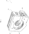
- numeral 10 indicates an apparatus for automatically dispensing discrete sections of double-sided adhesive tape with a desired length and for applying the discrete sections of double-sided adhesive tape onto an application surface (not shown).
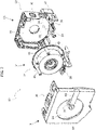
- the apparatus 10 comprises a casing 12, a reel support unit 14, and a lid 16.
- the casing 12 comprises a rear wall 18 having a central hole 20 and a side wall 22.
- the casing 12 carries an applicator roller 24 extending orthogonal to the rear wall 18 and idle around its own axis.
- the applicator roller 24 is configured to press a section of double-sided adhesive tape against an application surface.
- the casing 12 comprises a winding pin 26 carried by the rear wall 18 and parallel to the applicator roller 24.
- the winding pin 26 is driven into rotation by means of an electric motor 28 and it is configured to wind a support film that is detached from the double-sided adhesive tape.
- the winding pin 26 can be provided with a slot 30 within which the end of the support film can be inserted to facilitate winding the support film onto the winding pin 26.
- the casing 12 may comprise one or more guiding rollers 32 parallel to the applicator roller 24 and to the winding pin 26 and arranged to guide the support film onto the winding pin 26.
- the casing 12 comprises also an adjustment screw 34 driven into rotation by means of an electric motor 36.
- the adjustment screw 34 can be oriented orthogonal relative to the axes of the applicator roller 24 and winding pin 26.
- the adjustment screw 34 can be replaced by a gear driven into rotation by a motor having its own rotation axis parallel to the axes of the applicator roller 24 and winding pin 26.
- the adjustment screw 34 (or the gear) is part of an adjustment mechanism configured to adjust the length of the sections of double-sided adhesive tape to be dispensed.
- the reel support unit 14 comprises a base plate 38 that is rotatable relative to the casing 12 around an axis A.
- the base plate 38 may have a cylindrical projection 40 rotatably engaging the hole 20 of the rear wall 18 of the casing 12.
- the base plate 38 may rest on the rear surface 18 of the casing 12.
- the base plate 38 has a peripheral toothing 42 meshing with the adjustment screw 34.
- the peripheral toothing 42 of the base plate 38 and the adjustment screw 34 of the casing 12 form an adjustment mechanism which allows adjusting the angular position of the base plate 38 relative to the casing 12 around the axis A.
- the base plate 38 carries a hub 44 on which a reel 46 of double-sided adhesive tape is intended to be mounted.
- the hub 44 is rotatable relative to the base plate 38 around the axis A so as to allow the double-sided adhesive tape to unwind from the reel 46.
- the base plate 38 carries a plurality of return pins 48 with respective axes parallel to the axis A.
- the return pins 48 may be arranged on a circumference surrounding the reel 46.
- the reel support unit 14 carries a cutting device 50 configured to carry out the transversal cutting of successive sections unwound from the reel 46 of double-sided tape.
- the cutting device 50 comprises a bracket 52 fixed relative to the base plate 38 and carrying a guide 54 oriented parallel to the axis A.
- a slider 56 is movable along the guide 54. The movement of the slider 56 along the guide 54 is controlled by an electric actuator (not shown).
- the slider 56 carries a blade 58 that is pressed elastically, for example, by means of an elastic element 60, toward the tape to be cut.
- the blade 58 is pressed against the double-sided adhesive tape by a determined force so as to carry out the cutting of the double-sided adhesive tape only without cutting the support film applied to the external surface of the double-sided adhesive tape.
- the cutting of the double-sided adhesive tape is carried out by a cutting movement along a transverse rectilinear direction, which improves the effectiveness and quality of cutting relative to known solutions that use rotating cutting blades.
- the lid 16 comprises a front wall 62 having an opening 64 sized so as to allow the passage of a reel 36 of double-sided adhesive tape.
- the lid 16 is connected to the casing 12 by means of connecting features 66 which engage corresponding connecting features formed on the side wall 22 of the casing 12. Screws may also be provided so as to secure the lid 16 to the casing 12.
- the lid 16 may comprise an arm 68 articulated to the front wall 62 by means of a pin 70.
- the arm 68 carries a magnet 72 located at the center of the opening 64 that acts on a metal ring located at the front end of the hub 44 of the reel support unit 14.
- the magnet 72 holds the hub 44 to prevent undesired rotation movements of the reel 46.
- the magnet 72 still allows the rotation of the hub 44 and reel 46 mounted thereon when the double-sided adhesive tape is positively unwound from the reel 46.
- the arm 68 articulated to the front wall 62 of the lid 16 allows the opening 64 to be released so as to replace the reel 46 without necessity of removing the lid 16.
- the length of the section of double-sided adhesive tape to be dispensed as desired is set.
- the selection of the length of the tape to be dispensed is carried out by controlling the rotation of the whole reel support unit 14 around to the axis A by means of the motor 36 and of the screw 34 meshing with the peripheral toothing 42 of the base plate 38 of the reel support unit 14.
- the rotation of the base plate 38 around the axis A varies the angular position of the cutting device 50 relative to the casing 12 and therfore relative to the applicator roller 24.
- the reel support unit 14 might be shiftable relative to the casing along a transversal direction relative to the axis A and the adjustment of the length of the tape to be dispensed may be carried out by controlling the translation of the reel support unit 14 along said transversal direction.
- the double-sided adhesive tape that is unwound from the reel 46 passes over one or more return pins 48 carried by the base plate 38 and is guided toward the application roller 24.
- the film applied onto the external surface of the double-sided adhesive tape detaches from the double-sided adhesive tape at the application roller 24 and, guided by the guiding rollers 32, winds around the winding pin 26.
- the cutting unit 50 carries out the transversal cutting of the double-sided adhesive tape, without cutting the support film of the tape.
- the length of the double-sided adhesive tape to be dispensed corresponds to the length of the section of tape between the line of transversal cutting and the end of the tape located on the applicator roller 24.
- the length of the section of tape to be dispensed is indicated by the dashed line 80 in Figures 11 , 12 , and 13 .
- Figure 11 shows the configuration of the apparatus 10 which corresponds to the minimum length of the section of double-sided adhesive tape to be dispensed
- Figure 13 illustrates the configuration of the apparatus which corresponds to the maximum length of the section of double-sided adhesive tape to be dispensed.
- the apparatus 10 allows to set any length of sections of double-sided adhesive tape in between the minimum value shown in Figure 11 and the maximum value shown in Figure 13 .
- the application roller 24 is placed onto the application surface onto which the section of double-sided adhesive tape has to be applied. Therefore, the whole apparatus 10 is moved along a rectilinear direction parallel to the application surface and transversal relative to the axis A. Such movement can be carried out by means of a mechanical hand, for example an anthropomorphic robot.
- the support film While the section of double-sided adhesive tape is gradually applied onto the application surface, the support film is detached from the tape and wound onto the winding pin 26. The traction of the support film causes the unwinding of the tape from the reel 46.
- the length of the double-sided adhesive tape to be dispensed is configurable according to needs, which allows various lengths of double-sided adhesive tape to be applied according to needs, without the need for manual interventions.
- Another relevant characteristic of the apparatus according to the invention is that the cutting of the tape is carried out by means of a linearly movable sliding blade.
- the apparatus according to the invention is particularly compact and allows fully automatic operation.
Landscapes
- Adhesive Tape Dispensing Devices (AREA)
Abstract
Description
- The present invention relates to an apparatus and a method for dispensing discrete sections of double-sided adhesive tape.
- The invention has been developed, in particular, regarding its application to the field of producing sanitary articles, such as sanitary absorbent towels, baby diapers, panty diapers, diapers for incontinent adults, bandages, face protection masks, packaging, etc.
- However, the invention can be used in all sectors where the need arises to automatically dispense discrete sections of double-sided adhesive tape.
- In machines for producing sanitary articles large quantities of web materials (for example, non-woven fabrics) contained in reels are used.
- Modern machines for producing sanitary articles operate at increasingly higher speeds, so that the unwinding speed of the web materials from the reels tends to an ever-increasing growth, increasing the frequency with which finished reels have to be replaced with new reels.
- Replacing a finished reel with a new reel must be carried out by maintaining continuity between the web material coming from the reel close to finishing and the web material coming from the new reel, so as not to interrupt the operation of the machine.
- The continuity of the web material is obtained by making a joint between the tail portion of the web that is unwinding from a reel close to finishing with the leading portion of a web wound on a new reel.
- In order to quickly and automatically make the joint of the reels on the unwinding assemblies, it is necessary to preliminarily carry out an adequate preparation of the leading edges of the new reels.
- Preparing the edges of the reels consists in removing a leading section of the new reel which is usually soiled or damaged and in applying onto the leading end of the web of the new reel a section of double-sided adhesive tape, which is used for joining the leading section of the web material of a new reel with the tail section of the web material of a reel close to finishing.
- Double-sided adhesive tapes are supplied in reels with an undefined length and consist of a support provided with two layers of adhesive on both the faces. A thin support film is applied onto the external adhesive layer so as to prevent the external adhesive layer from sticking to the inner adhesive layer of the successive turn. The double-sided adhesive tape is cut in discrete sections having the desired length and the side opposite to the one bearing the film is applied onto the application surface. Therefore, the film is removed so as to present the adhesive on the external side of the web. Since double-sided adhesive tapes are sticky on both sides, automating the step of cutting, applying and removing the film is very complex. In many industrial plants the step of applying the sections of double-sided adhesive tape is still done manually.
-
US3765992 describes a mechanism for transferring a predetermined length of double-sided adhesive tape onto objects starting from a continuous web carried by a detachable film. The device includes means for cutting the double-sided adhesive tape for forming a discrete section of a predetermined length and placing then the discrete sections onto an application surface by means of a pressing element. The length of the sections of double-sided adhesive tape to be dispensed is always fixed. In case a section having a high length of double-sided adhesive tape has to be applied onto very thin webs, there is the risk that the double-sided adhesive tape remains adherent to the film instead to the application surface or that the thin web is damaged during the separation of the film. -
EP0755890 B1 describes a mechanism for automatically applying sections of double-sided adhesive tape onto an object, which operates in a similar way to the device ofUS3765992 and is affected by the same drawbacks. -
JP2000302316 A -
JP4678733 B2 -
KR101297640 B1 - The object of the present invention is to provide an apparatus and a method for dispensing discrete sections of double-sided adhesive tape that overcome the problems of the prior art.
- According to the present invention, this object is achieved by an apparatus and a method having the characteristics forming the subject of claims 1 e 9.
- The present invention provides a reconfigurable dispenser of double-sided adhesive tape which allows the user to set the required length of the section of double-sided adhesive tape to be dispensed. The length of the tape section can be set by varying the position of the cutting zone of the double-sided adhesive tape. In a possible embodiment, the cutting unit is mounted on a rotatable support that carries the reel of double-sided adhesive tape. The adjustment of the length of the tape section can be set by varying the angular position of the rotatable support.
- The application of the section of tape can be carried out onto surfaces of various, both soft and hard, nature without risks of material damaging during the separation of the film from the double-sided adhesive tape.
- Further characteristics and advantages of the present invention will be evident in the following detailed description, given purely by way of nonlimiting example, wherein:
-
Figure 1 is a perspective view of an apparatus according to the present invention, -
Figure 2 is an exploded perspective view of the apparatus ofFigure 1 , -
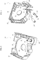
Figure 3 is a perspective view of the part indicated by the arrow III inFigure 2 , -
Figure 4 is an exploded perspective view of the component illustrated inFigure 3 , -
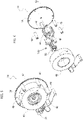
Figure 5 is a perspective view on a larger scale of the portion indicated by the arrow V inFigure 2 , -
Figure 6 is an exploded perspective view of the components illustrated inFigure 5 , -
Figure 7 is an exploded perspective view from a different angle of the components ofFigure 6 , -
Figure 8 is a perspective view on a larger scale of the part indicated by the arrow VIII inFigure 6 , -
Figure 9 is an exploded perspective view of the part illustrated inFigure 8 , -
Figure 10 is an exploded perspective view of the part indicated by the arrow X inFigure 2 , -
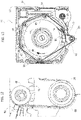
Figure 11 is a front view showing the operation of the apparatus according to the invention in a first configuration, -
Figure 12 is an enlarged detail of the part indicated by the arrow XII inFigure 11 , and -
Figure 13 is a front view showing the operation of the apparatus according to the invention in a second configuration. - It will be appreciated that the various figures may not be represented on the same scale and that some components may be omitted for easier understanding of the figures.
- With reference to
Figures 1 and2 ,numeral 10 indicates an apparatus for automatically dispensing discrete sections of double-sided adhesive tape with a desired length and for applying the discrete sections of double-sided adhesive tape onto an application surface (not shown). - With reference to
Figures 2 , theapparatus 10 comprises acasing 12, areel support unit 14, and alid 16. - With reference to
Figures 3 and 4 , thecasing 12 comprises arear wall 18 having acentral hole 20 and aside wall 22. Thecasing 12 carries anapplicator roller 24 extending orthogonal to therear wall 18 and idle around its own axis. Theapplicator roller 24 is configured to press a section of double-sided adhesive tape against an application surface. - The
casing 12 comprises a windingpin 26 carried by therear wall 18 and parallel to theapplicator roller 24. The windingpin 26 is driven into rotation by means of anelectric motor 28 and it is configured to wind a support film that is detached from the double-sided adhesive tape. The windingpin 26 can be provided with aslot 30 within which the end of the support film can be inserted to facilitate winding the support film onto the windingpin 26. Thecasing 12 may comprise one ormore guiding rollers 32 parallel to theapplicator roller 24 and to the windingpin 26 and arranged to guide the support film onto the windingpin 26. - The
casing 12 comprises also anadjustment screw 34 driven into rotation by means of anelectric motor 36. In the illustrated embodiment, theadjustment screw 34 can be oriented orthogonal relative to the axes of theapplicator roller 24 and windingpin 26. In a possible embodiment (not shown), theadjustment screw 34 can be replaced by a gear driven into rotation by a motor having its own rotation axis parallel to the axes of theapplicator roller 24 and windingpin 26. As it will become clearer in the following, the adjustment screw 34 (or the gear) is part of an adjustment mechanism configured to adjust the length of the sections of double-sided adhesive tape to be dispensed. - With reference to
Figures 2 and5-7 , thereel support unit 14 comprises abase plate 38 that is rotatable relative to thecasing 12 around an axis A. With reference toFigure 7 , thebase plate 38 may have acylindrical projection 40 rotatably engaging thehole 20 of therear wall 18 of thecasing 12. Thebase plate 38 may rest on therear surface 18 of thecasing 12. Thebase plate 38 has aperipheral toothing 42 meshing with theadjustment screw 34. Theperipheral toothing 42 of thebase plate 38 and theadjustment screw 34 of thecasing 12 form an adjustment mechanism which allows adjusting the angular position of thebase plate 38 relative to thecasing 12 around the axis A. - The
base plate 38 carries ahub 44 on which areel 46 of double-sided adhesive tape is intended to be mounted. Thehub 44 is rotatable relative to thebase plate 38 around the axis A so as to allow the double-sided adhesive tape to unwind from thereel 46. - The
base plate 38 carries a plurality of return pins 48 with respective axes parallel to the axis A. The return pins 48 may be arranged on a circumference surrounding thereel 46. - With reference to
Figures 8 and 9 , thereel support unit 14 carries acutting device 50 configured to carry out the transversal cutting of successive sections unwound from thereel 46 of double-sided tape. The cuttingdevice 50 comprises abracket 52 fixed relative to thebase plate 38 and carrying aguide 54 oriented parallel to the axis A. Aslider 56 is movable along theguide 54. The movement of theslider 56 along theguide 54 is controlled by an electric actuator (not shown). Theslider 56 carries ablade 58 that is pressed elastically, for example, by means of anelastic element 60, toward the tape to be cut. Theblade 58 is pressed against the double-sided adhesive tape by a determined force so as to carry out the cutting of the double-sided adhesive tape only without cutting the support film applied to the external surface of the double-sided adhesive tape. The cutting of the double-sided adhesive tape is carried out by a cutting movement along a transverse rectilinear direction, which improves the effectiveness and quality of cutting relative to known solutions that use rotating cutting blades. - With reference to
Figure 10 , thelid 16 comprises afront wall 62 having anopening 64 sized so as to allow the passage of areel 36 of double-sided adhesive tape. Thelid 16 is connected to thecasing 12 by means of connectingfeatures 66 which engage corresponding connecting features formed on theside wall 22 of thecasing 12. Screws may also be provided so as to secure thelid 16 to thecasing 12. - The
lid 16 may comprise anarm 68 articulated to thefront wall 62 by means of apin 70. Thearm 68 carries amagnet 72 located at the center of theopening 64 that acts on a metal ring located at the front end of thehub 44 of thereel support unit 14. Themagnet 72 holds thehub 44 to prevent undesired rotation movements of thereel 46. Themagnet 72 still allows the rotation of thehub 44 and reel 46 mounted thereon when the double-sided adhesive tape is positively unwound from thereel 46. Thearm 68 articulated to thefront wall 62 of thelid 16 allows theopening 64 to be released so as to replace thereel 46 without necessity of removing thelid 16. - The operation of the
apparatus 10 according to the present invention is shown inFigures 11 ,12 and 13 . - At first, the length of the section of double-sided adhesive tape to be dispensed as desired is set. The selection of the length of the tape to be dispensed is carried out by controlling the rotation of the whole
reel support unit 14 around to the axis A by means of themotor 36 and of thescrew 34 meshing with theperipheral toothing 42 of thebase plate 38 of thereel support unit 14. The rotation of thebase plate 38 around the axis A varies the angular position of the cuttingdevice 50 relative to thecasing 12 and therfore relative to theapplicator roller 24. - In a possible embodiment, the
reel support unit 14 might be shiftable relative to the casing along a transversal direction relative to the axis A and the adjustment of the length of the tape to be dispensed may be carried out by controlling the translation of thereel support unit 14 along said transversal direction. - The double-sided adhesive tape that is unwound from the
reel 46 passes over one or more return pins 48 carried by thebase plate 38 and is guided toward theapplication roller 24. The film applied onto the external surface of the double-sided adhesive tape detaches from the double-sided adhesive tape at theapplication roller 24 and, guided by the guidingrollers 32, winds around the windingpin 26. - The cutting
unit 50 carries out the transversal cutting of the double-sided adhesive tape, without cutting the support film of the tape. The length of the double-sided adhesive tape to be dispensed corresponds to the length of the section of tape between the line of transversal cutting and the end of the tape located on theapplicator roller 24. The length of the section of tape to be dispensed is indicated by the dashedline 80 inFigures 11 ,12 , and13 .Figure 11 shows the configuration of theapparatus 10 which corresponds to the minimum length of the section of double-sided adhesive tape to be dispensed andFigure 13 illustrates the configuration of the apparatus which corresponds to the maximum length of the section of double-sided adhesive tape to be dispensed. Theapparatus 10 allows to set any length of sections of double-sided adhesive tape in between the minimum value shown inFigure 11 and the maximum value shown inFigure 13 . - After having carried out the cutting of the double-sided adhesive tape at the desired length, the
application roller 24 is placed onto the application surface onto which the section of double-sided adhesive tape has to be applied. Therefore, thewhole apparatus 10 is moved along a rectilinear direction parallel to the application surface and transversal relative to the axis A. Such movement can be carried out by means of a mechanical hand, for example an anthropomorphic robot. - While the section of double-sided adhesive tape is gradually applied onto the application surface, the support film is detached from the tape and wound onto the winding
pin 26. The traction of the support film causes the unwinding of the tape from thereel 46. - When the application of the section of cut tape is ended, the end of a new section of tape is located at the
application roller 24. At this point, the transversal cutting is carried out again at the desired length and the process repeats as described above. - From the description above, it is clear that the length of the double-sided adhesive tape to be dispensed is configurable according to needs, which allows various lengths of double-sided adhesive tape to be applied according to needs, without the need for manual interventions.
- Another relevant characteristic of the apparatus according to the invention is that the cutting of the tape is carried out by means of a linearly movable sliding blade.
- The apparatus according to the invention is particularly compact and allows fully automatic operation.
- Of course, without prejudice to the principle of the invention, the details of construction and the embodiments may be widely varied with respect to those described and illustrated here, without departing from the scope of the invention as defined by the claims that follow.
Claims (10)
- An apparatus for dispensing discrete sections of double-sided adhesive tape, comprising:- a casing (12) carrying an applicator roller (24) and a motorized winding pin (26) configured to wind a support film detached from an external surface of the double-sided adhesive tape,- a reel support unit (14) comprising: a base plate (38), a hub (44) rotatable relative to the base plate (38) and configured to support a reel of double-sided tape (46), a plurality of return pins (48) carried by the base plate (38) and arranged to guide the double-sided adhesive tape unwound from said reel (46), and a cutting device (50) configured to transversely cut the double-sided tape unwound from the reel and to form successive discrete sections of double-sided tape, and- an adjustment mechanism (34, 42) configured to vary the position of said base plate (38) with respect to the casing (12) to vary the length of the discrete sections of double-sided tape to be dispensed.
- An apparatus according to claim 1, wherein the base plate (38) of the reel support unit (14) is rotatable relative to the housing (12) and wherein said adjustment mechanism (34, 42) is configured to vary the angular position of the base plate (38) with respect to the casing (12).
- An apparatus according to claim 2, wherein said adjustment mechanism comprises an adjustment screw (34) carried by the housing (12) and which meshes with a toothing (42) of the base plate (38).
- An apparatus according to any one of the preceding claims, wherein said cutting device (50) comprises a straight guide (54) fixed with respect to the base plate (38), a slider (56) movable along said guide (54) in a rectilinear direction transversal with respect to the tape, and a sliding blade (58) carried by said slider.
- An apparatus according to claim 4, wherein the cutting device (50) comprises an elastic element (60) arranged to elastically press the blade (58) against the tape with a determined force so as to carry out cutting of the tape without cutting the support film.
- An apparatus according to any one of the preceding claims, wherein said casing (12) comprises a lid (16) provided with an opening (64) sized to allow the passage of a reel of double-sided adhesive tape (46) .
- An apparatus according to claim 6, wherein said lid (16) carries a magnet (72) which acts on a front end of said hub (44).
- An apparatus according to claim 1, wherein said return pins (48) are arranged along a circumference surrounding the reel of double-sided tape (46) mounted on said hub (44).
- A method for dispensing discrete sections of double-sided tape, comprising:- rotatably arranging a reel of double-sided tape (46) in a casing (12),- unwinding a section of double-sided tape from the reel (46) and passing the section of double-sided tape unwound from the reel (46) over an applicator roller (24) carried by said casing (12),- detaching a support film from an external surface of the section of double-sided tape unwound from the reel (46),- winding the support film detached from the double-sided tape on a motorized winding pin (26) carried by the casing (12),- providing a cutting device (50) configured to transversely cut the double-sided tape,- adjusting the length of the section of discrete double-sided tape to be dispensed by varying the angular position of the cutting device (50) with respect to the applicator roller (24), and- transversely cutting the section of double-sided tape to be dispensed by means of said cutting device (50) .
- A method according to claim 9, wherein the adjustment of the length of the discrete section of double-sided tape to be dispensed is carried out by varying the angular position of the cutting device (50) with respect to the casing (12).
Applications Claiming Priority (1)
| Application Number | Priority Date | Filing Date | Title |
|---|---|---|---|
| IT202000024892 | 2020-10-21 |
Publications (2)
| Publication Number | Publication Date |
|---|---|
| EP3988486A1 true EP3988486A1 (en) | 2022-04-27 |
| EP3988486B1 EP3988486B1 (en) | 2023-08-02 |
Family
ID=74068597
Family Applications (1)
| Application Number | Title | Priority Date | Filing Date |
|---|---|---|---|
| EP21203082.9A Active EP3988486B1 (en) | 2020-10-21 | 2021-10-18 | An apparatus and method for dispensing sections of double-sided adhesive tape |
Country Status (4)
| Country | Link |
|---|---|
| US (1) | US12325608B2 (en) |
| EP (1) | EP3988486B1 (en) |
| CN (1) | CN114380118A (en) |
| PL (1) | PL3988486T3 (en) |
Citations (7)
| Publication number | Priority date | Publication date | Assignee | Title |
|---|---|---|---|---|
| US3765992A (en) | 1971-12-30 | 1973-10-16 | Minnesota Mining & Mfg | Strip adhesive application mechanism |
| JPS60197565A (en) * | 1984-03-15 | 1985-10-07 | Akitoshi Suzuki | Device for applying automatically double-sided adhesive tape |
| US4608110A (en) * | 1985-02-19 | 1986-08-26 | Smith Ward C | Pressure sensitive label dispenser |
| JP2000302316A (en) | 1999-04-21 | 2000-10-31 | Takayasu Takebe | Pressure sensitive adhesive double coated tape sticker, and sticking method for the tape |
| EP0755890B1 (en) | 1995-07-28 | 2001-11-14 | Japan Tobacco Inc. | Adhesive tape dispensing apparatus |
| JP4678733B2 (en) | 2005-12-16 | 2011-04-27 | ニチバン株式会社 | Double-sided tape dispenser |
| KR101297640B1 (en) | 2012-03-05 | 2013-08-19 | (주)세줄 | Tape dispenser |
Family Cites Families (15)
| Publication number | Priority date | Publication date | Assignee | Title |
|---|---|---|---|---|
| US4346550A (en) * | 1980-06-27 | 1982-08-31 | Westinghouse Electric Corp. | Tape wrapping apparatus |
| FR2590069B1 (en) * | 1985-11-14 | 1987-12-11 | Alsthom | WRAPPER FOR HOT WRAPPING OF AN ELECTRIC CONDUCTOR |
| US4867833A (en) * | 1987-09-14 | 1989-09-19 | Carl Strutz & Company, Inc. | Butt-cut label dispenser |
| US5478000A (en) * | 1995-01-03 | 1995-12-26 | Jensen R&D Corporation | Device for automatically cutting and dispensing tape |
| DE19546581C2 (en) * | 1995-12-13 | 2000-01-20 | Silu Verwaltung Ag | Device for applying adhesive assembly tape |
| KR100614878B1 (en) * | 2004-04-21 | 2006-08-25 | 이상철 | Dispenser of Double-Faced adhesive tape |
| US20070125474A1 (en) | 2005-12-05 | 2007-06-07 | Huber Engineered Woods L.L.C. | Handheld tape applicator and components thereof, and their methods of use |
| US7762492B2 (en) | 2006-04-13 | 2010-07-27 | Muderlak Design, Inc. | Handle cover dispenser |
| EP2025633A1 (en) * | 2007-08-10 | 2009-02-18 | CECC Beheer B.V. | A tape dispenser and a method of taping |
| CN103183252A (en) * | 2013-04-08 | 2013-07-03 | 曾小林 | An easy-to-use multifunctional adhesive tape cutter |
| CN203976072U (en) * | 2014-05-28 | 2014-12-03 | 宁波康达电子有限公司 | A kind of tape automatic cutting machine |
| MX384809B (en) * | 2015-02-18 | 2025-03-14 | Lamus Tech Inc | MANUAL TAPPING IMPLEMENT. |
| ES2758367T3 (en) * | 2015-06-10 | 2020-05-05 | Custom Spa | Printing apparatus |
| CN210824758U (en) * | 2019-08-29 | 2020-06-23 | 汕头市德福包装材料有限公司 | Edge cutting device for production of aluminized packaging film |
| US11814257B2 (en) * | 2020-10-29 | 2023-11-14 | Jjs Application Technologies Ltd. | Adhesive tape dispenser head |
-
2021
- 2021-10-18 PL PL21203082.9T patent/PL3988486T3/en unknown
- 2021-10-18 EP EP21203082.9A patent/EP3988486B1/en active Active
- 2021-10-20 CN CN202111220813.8A patent/CN114380118A/en active Pending
- 2021-10-20 US US17/505,839 patent/US12325608B2/en active Active
Patent Citations (7)
| Publication number | Priority date | Publication date | Assignee | Title |
|---|---|---|---|---|
| US3765992A (en) | 1971-12-30 | 1973-10-16 | Minnesota Mining & Mfg | Strip adhesive application mechanism |
| JPS60197565A (en) * | 1984-03-15 | 1985-10-07 | Akitoshi Suzuki | Device for applying automatically double-sided adhesive tape |
| US4608110A (en) * | 1985-02-19 | 1986-08-26 | Smith Ward C | Pressure sensitive label dispenser |
| EP0755890B1 (en) | 1995-07-28 | 2001-11-14 | Japan Tobacco Inc. | Adhesive tape dispensing apparatus |
| JP2000302316A (en) | 1999-04-21 | 2000-10-31 | Takayasu Takebe | Pressure sensitive adhesive double coated tape sticker, and sticking method for the tape |
| JP4678733B2 (en) | 2005-12-16 | 2011-04-27 | ニチバン株式会社 | Double-sided tape dispenser |
| KR101297640B1 (en) | 2012-03-05 | 2013-08-19 | (주)세줄 | Tape dispenser |
Also Published As
| Publication number | Publication date |
|---|---|
| PL3988486T3 (en) | 2023-12-27 |
| CN114380118A (en) | 2022-04-22 |
| US12325608B2 (en) | 2025-06-10 |
| EP3988486B1 (en) | 2023-08-02 |
| US20220119216A1 (en) | 2022-04-21 |
Similar Documents
| Publication | Publication Date | Title |
|---|---|---|
| US6808581B2 (en) | Method and apparatus for automatically applying a flying splicing tape to a roll of sheet material | |
| US5322230A (en) | Method and apparatus for preparing a replacement paper roll for flying roll change, particularly to supply paper to a rotary printing press | |
| US3915399A (en) | Apparatus and method for splicing the trailing end of an expiring web to the leading end of a new web | |
| US4097323A (en) | Butt-splicer | |
| EP1041131A1 (en) | Double faced tape, method of and apparatus for manufacturing same | |
| KR20090057256A (en) | Film automatic winding device, slit winding system and manufacturing method of winding film | |
| PL176851B1 (en) | Apparatus for sticking trailing end of reeled web of material | |
| JP3300031B2 (en) | METHOD AND APPARATUS FOR PREPARING A PRINTED WEB ROLL FOR REPLACEMENT OF A PRINTED WEB ROLL DURING MACHINE OPERATION | |
| CA2161657A1 (en) | Tape supply and applicator system including a tape splicing mechanism | |
| KR20090037336A (en) | Hand-held device for releasing adhesive tape with adhesive on both sides, wherein at least one of the two adhesive sides is lined with release material | |
| CS234036B2 (en) | Method of replacement of first empty coil with belt material by second new coil and equipment for its application | |
| US5368253A (en) | Continuous rewind with no-fold-back splicer | |
| US5823461A (en) | No-fold back splicer with electrostatic web transfer device | |
| US12325608B2 (en) | Apparatus and method for dispensing sections of double-sided adhesive tape | |
| US5628866A (en) | Masking machine | |
| EP3988484B1 (en) | A method and apparatus for preparing edges of reels of web material | |
| US4175999A (en) | Apparatus for loading magnetic tape cassettes with magnetic tape | |
| EP1648805B1 (en) | Method and apparatus for splicing webs | |
| US5076878A (en) | Device for applying adhesive to elongate members | |
| US4024782A (en) | Apparatus for cutting the trailing end of an expiring web | |
| EP0733571B1 (en) | Web winding apparatus | |
| JPH0550426B2 (en) | ||
| CN216889300U (en) | Paper changing device and rewinding machine | |
| JPS6261490B2 (en) | ||
| EP0604633A1 (en) | A multifunctional machine for the joining calendering, cutting and rewinding of films. |
Legal Events
| Date | Code | Title | Description |
|---|---|---|---|
| PUAI | Public reference made under article 153(3) epc to a published international application that has entered the european phase |
Free format text: ORIGINAL CODE: 0009012 |
|
| STAA | Information on the status of an ep patent application or granted ep patent |
Free format text: STATUS: THE APPLICATION HAS BEEN PUBLISHED |
|
| AK | Designated contracting states |
Kind code of ref document: A1 Designated state(s): AL AT BE BG CH CY CZ DE DK EE ES FI FR GB GR HR HU IE IS IT LI LT LU LV MC MK MT NL NO PL PT RO RS SE SI SK SM TR |
|
| STAA | Information on the status of an ep patent application or granted ep patent |
Free format text: STATUS: REQUEST FOR EXAMINATION WAS MADE |
|
| 17P | Request for examination filed |
Effective date: 20220803 |
|
| RBV | Designated contracting states (corrected) |
Designated state(s): AL AT BE BG CH CY CZ DE DK EE ES FI FR GB GR HR HU IE IS IT LI LT LU LV MC MK MT NL NO PL PT RO RS SE SI SK SM TR |
|
| GRAP | Despatch of communication of intention to grant a patent |
Free format text: ORIGINAL CODE: EPIDOSNIGR1 |
|
| STAA | Information on the status of an ep patent application or granted ep patent |
Free format text: STATUS: GRANT OF PATENT IS INTENDED |
|
| INTG | Intention to grant announced |
Effective date: 20230519 |
|
| GRAS | Grant fee paid |
Free format text: ORIGINAL CODE: EPIDOSNIGR3 |
|
| GRAA | (expected) grant |
Free format text: ORIGINAL CODE: 0009210 |
|
| STAA | Information on the status of an ep patent application or granted ep patent |
Free format text: STATUS: THE PATENT HAS BEEN GRANTED |
|
| AK | Designated contracting states |
Kind code of ref document: B1 Designated state(s): AL AT BE BG CH CY CZ DE DK EE ES FI FR GB GR HR HU IE IS IT LI LT LU LV MC MK MT NL NO PL PT RO RS SE SI SK SM TR |
|
| REG | Reference to a national code |
Ref country code: GB Ref legal event code: FG4D |
|
| REG | Reference to a national code |
Ref country code: CH Ref legal event code: EP |
|
| REG | Reference to a national code |
Ref country code: DE Ref legal event code: R096 Ref document number: 602021003954 Country of ref document: DE |
|
| REG | Reference to a national code |
Ref country code: IE Ref legal event code: FG4D |
|
| REG | Reference to a national code |
Ref country code: LT Ref legal event code: MG9D |
|
| REG | Reference to a national code |
Ref country code: NL Ref legal event code: MP Effective date: 20230802 |
|
| REG | Reference to a national code |
Ref country code: AT Ref legal event code: MK05 Ref document number: 1594537 Country of ref document: AT Kind code of ref document: T Effective date: 20230802 |
|
| PG25 | Lapsed in a contracting state [announced via postgrant information from national office to epo] |
Ref country code: GR Free format text: LAPSE BECAUSE OF FAILURE TO SUBMIT A TRANSLATION OF THE DESCRIPTION OR TO PAY THE FEE WITHIN THE PRESCRIBED TIME-LIMIT Effective date: 20231103 |
|
| PG25 | Lapsed in a contracting state [announced via postgrant information from national office to epo] |
Ref country code: IS Free format text: LAPSE BECAUSE OF FAILURE TO SUBMIT A TRANSLATION OF THE DESCRIPTION OR TO PAY THE FEE WITHIN THE PRESCRIBED TIME-LIMIT Effective date: 20231202 |
|
| PG25 | Lapsed in a contracting state [announced via postgrant information from national office to epo] |
Ref country code: SE Free format text: LAPSE BECAUSE OF FAILURE TO SUBMIT A TRANSLATION OF THE DESCRIPTION OR TO PAY THE FEE WITHIN THE PRESCRIBED TIME-LIMIT Effective date: 20230802 Ref country code: RS Free format text: LAPSE BECAUSE OF FAILURE TO SUBMIT A TRANSLATION OF THE DESCRIPTION OR TO PAY THE FEE WITHIN THE PRESCRIBED TIME-LIMIT Effective date: 20230802 Ref country code: PT Free format text: LAPSE BECAUSE OF FAILURE TO SUBMIT A TRANSLATION OF THE DESCRIPTION OR TO PAY THE FEE WITHIN THE PRESCRIBED TIME-LIMIT Effective date: 20231204 Ref country code: NO Free format text: LAPSE BECAUSE OF FAILURE TO SUBMIT A TRANSLATION OF THE DESCRIPTION OR TO PAY THE FEE WITHIN THE PRESCRIBED TIME-LIMIT Effective date: 20231102 Ref country code: NL Free format text: LAPSE BECAUSE OF FAILURE TO SUBMIT A TRANSLATION OF THE DESCRIPTION OR TO PAY THE FEE WITHIN THE PRESCRIBED TIME-LIMIT Effective date: 20230802 Ref country code: LV Free format text: LAPSE BECAUSE OF FAILURE TO SUBMIT A TRANSLATION OF THE DESCRIPTION OR TO PAY THE FEE WITHIN THE PRESCRIBED TIME-LIMIT Effective date: 20230802 Ref country code: LT Free format text: LAPSE BECAUSE OF FAILURE TO SUBMIT A TRANSLATION OF THE DESCRIPTION OR TO PAY THE FEE WITHIN THE PRESCRIBED TIME-LIMIT Effective date: 20230802 Ref country code: IS Free format text: LAPSE BECAUSE OF FAILURE TO SUBMIT A TRANSLATION OF THE DESCRIPTION OR TO PAY THE FEE WITHIN THE PRESCRIBED TIME-LIMIT Effective date: 20231202 Ref country code: HR Free format text: LAPSE BECAUSE OF FAILURE TO SUBMIT A TRANSLATION OF THE DESCRIPTION OR TO PAY THE FEE WITHIN THE PRESCRIBED TIME-LIMIT Effective date: 20230802 Ref country code: GR Free format text: LAPSE BECAUSE OF FAILURE TO SUBMIT A TRANSLATION OF THE DESCRIPTION OR TO PAY THE FEE WITHIN THE PRESCRIBED TIME-LIMIT Effective date: 20231103 Ref country code: FI Free format text: LAPSE BECAUSE OF FAILURE TO SUBMIT A TRANSLATION OF THE DESCRIPTION OR TO PAY THE FEE WITHIN THE PRESCRIBED TIME-LIMIT Effective date: 20230802 Ref country code: AT Free format text: LAPSE BECAUSE OF FAILURE TO SUBMIT A TRANSLATION OF THE DESCRIPTION OR TO PAY THE FEE WITHIN THE PRESCRIBED TIME-LIMIT Effective date: 20230802 |
|
| PG25 | Lapsed in a contracting state [announced via postgrant information from national office to epo] |
Ref country code: ES Free format text: LAPSE BECAUSE OF FAILURE TO SUBMIT A TRANSLATION OF THE DESCRIPTION OR TO PAY THE FEE WITHIN THE PRESCRIBED TIME-LIMIT Effective date: 20230802 |
|
| PG25 | Lapsed in a contracting state [announced via postgrant information from national office to epo] |
Ref country code: SM Free format text: LAPSE BECAUSE OF FAILURE TO SUBMIT A TRANSLATION OF THE DESCRIPTION OR TO PAY THE FEE WITHIN THE PRESCRIBED TIME-LIMIT Effective date: 20230802 Ref country code: RO Free format text: LAPSE BECAUSE OF FAILURE TO SUBMIT A TRANSLATION OF THE DESCRIPTION OR TO PAY THE FEE WITHIN THE PRESCRIBED TIME-LIMIT Effective date: 20230802 Ref country code: ES Free format text: LAPSE BECAUSE OF FAILURE TO SUBMIT A TRANSLATION OF THE DESCRIPTION OR TO PAY THE FEE WITHIN THE PRESCRIBED TIME-LIMIT Effective date: 20230802 Ref country code: EE Free format text: LAPSE BECAUSE OF FAILURE TO SUBMIT A TRANSLATION OF THE DESCRIPTION OR TO PAY THE FEE WITHIN THE PRESCRIBED TIME-LIMIT Effective date: 20230802 Ref country code: DK Free format text: LAPSE BECAUSE OF FAILURE TO SUBMIT A TRANSLATION OF THE DESCRIPTION OR TO PAY THE FEE WITHIN THE PRESCRIBED TIME-LIMIT Effective date: 20230802 Ref country code: CZ Free format text: LAPSE BECAUSE OF FAILURE TO SUBMIT A TRANSLATION OF THE DESCRIPTION OR TO PAY THE FEE WITHIN THE PRESCRIBED TIME-LIMIT Effective date: 20230802 Ref country code: SK Free format text: LAPSE BECAUSE OF FAILURE TO SUBMIT A TRANSLATION OF THE DESCRIPTION OR TO PAY THE FEE WITHIN THE PRESCRIBED TIME-LIMIT Effective date: 20230802 |
|
| REG | Reference to a national code |
Ref country code: DE Ref legal event code: R097 Ref document number: 602021003954 Country of ref document: DE |
|
| PG25 | Lapsed in a contracting state [announced via postgrant information from national office to epo] |
Ref country code: MC Free format text: LAPSE BECAUSE OF FAILURE TO SUBMIT A TRANSLATION OF THE DESCRIPTION OR TO PAY THE FEE WITHIN THE PRESCRIBED TIME-LIMIT Effective date: 20230802 |
|
| PLBE | No opposition filed within time limit |
Free format text: ORIGINAL CODE: 0009261 |
|
| STAA | Information on the status of an ep patent application or granted ep patent |
Free format text: STATUS: NO OPPOSITION FILED WITHIN TIME LIMIT |
|
| REG | Reference to a national code |
Ref country code: BE Ref legal event code: MM Effective date: 20231031 |
|
| PG25 | Lapsed in a contracting state [announced via postgrant information from national office to epo] |
Ref country code: LU Free format text: LAPSE BECAUSE OF NON-PAYMENT OF DUE FEES Effective date: 20231018 |
|
| PG25 | Lapsed in a contracting state [announced via postgrant information from national office to epo] |
Ref country code: LU Free format text: LAPSE BECAUSE OF NON-PAYMENT OF DUE FEES Effective date: 20231018 |
|
| 26N | No opposition filed |
Effective date: 20240503 |
|
| PG25 | Lapsed in a contracting state [announced via postgrant information from national office to epo] |
Ref country code: SI Free format text: LAPSE BECAUSE OF FAILURE TO SUBMIT A TRANSLATION OF THE DESCRIPTION OR TO PAY THE FEE WITHIN THE PRESCRIBED TIME-LIMIT Effective date: 20230802 |
|
| PG25 | Lapsed in a contracting state [announced via postgrant information from national office to epo] |
Ref country code: BE Free format text: LAPSE BECAUSE OF NON-PAYMENT OF DUE FEES Effective date: 20231031 |
|
| PG25 | Lapsed in a contracting state [announced via postgrant information from national office to epo] |
Ref country code: IE Free format text: LAPSE BECAUSE OF NON-PAYMENT OF DUE FEES Effective date: 20231018 |
|
| PG25 | Lapsed in a contracting state [announced via postgrant information from national office to epo] |
Ref country code: IE Free format text: LAPSE BECAUSE OF NON-PAYMENT OF DUE FEES Effective date: 20231018 |
|
| PG25 | Lapsed in a contracting state [announced via postgrant information from national office to epo] |
Ref country code: BG Free format text: LAPSE BECAUSE OF FAILURE TO SUBMIT A TRANSLATION OF THE DESCRIPTION OR TO PAY THE FEE WITHIN THE PRESCRIBED TIME-LIMIT Effective date: 20230802 |
|
| PG25 | Lapsed in a contracting state [announced via postgrant information from national office to epo] |
Ref country code: BG Free format text: LAPSE BECAUSE OF FAILURE TO SUBMIT A TRANSLATION OF THE DESCRIPTION OR TO PAY THE FEE WITHIN THE PRESCRIBED TIME-LIMIT Effective date: 20230802 |
|
| REG | Reference to a national code |
Ref country code: CH Ref legal event code: PL |
|
| PG25 | Lapsed in a contracting state [announced via postgrant information from national office to epo] |
Ref country code: CH Free format text: LAPSE BECAUSE OF NON-PAYMENT OF DUE FEES Effective date: 20241031 |
|
| PG25 | Lapsed in a contracting state [announced via postgrant information from national office to epo] |
Ref country code: CY Free format text: LAPSE BECAUSE OF FAILURE TO SUBMIT A TRANSLATION OF THE DESCRIPTION OR TO PAY THE FEE WITHIN THE PRESCRIBED TIME-LIMIT; INVALID AB INITIO Effective date: 20211018 |
|
| PG25 | Lapsed in a contracting state [announced via postgrant information from national office to epo] |
Ref country code: TR Free format text: LAPSE BECAUSE OF FAILURE TO SUBMIT A TRANSLATION OF THE DESCRIPTION OR TO PAY THE FEE WITHIN THE PRESCRIBED TIME-LIMIT Effective date: 20230802 |
|
| PGFP | Annual fee paid to national office [announced via postgrant information from national office to epo] |
Ref country code: DE Payment date: 20251029 Year of fee payment: 5 |
|
| PGFP | Annual fee paid to national office [announced via postgrant information from national office to epo] |
Ref country code: IT Payment date: 20251021 Year of fee payment: 5 |
|
| PGFP | Annual fee paid to national office [announced via postgrant information from national office to epo] |
Ref country code: FR Payment date: 20251027 Year of fee payment: 5 |
|
| PGFP | Annual fee paid to national office [announced via postgrant information from national office to epo] |
Ref country code: PL Payment date: 20251006 Year of fee payment: 5 |
|
| PG25 | Lapsed in a contracting state [announced via postgrant information from national office to epo] |
Ref country code: HU Free format text: LAPSE BECAUSE OF FAILURE TO SUBMIT A TRANSLATION OF THE DESCRIPTION OR TO PAY THE FEE WITHIN THE PRESCRIBED TIME-LIMIT; INVALID AB INITIO Effective date: 20211018 |