EP3988468A1 - Package of drywall sections - Google Patents
Package of drywall sections Download PDFInfo
- Publication number
- EP3988468A1 EP3988468A1 EP20203296.7A EP20203296A EP3988468A1 EP 3988468 A1 EP3988468 A1 EP 3988468A1 EP 20203296 A EP20203296 A EP 20203296A EP 3988468 A1 EP3988468 A1 EP 3988468A1
- Authority
- EP
- European Patent Office
- Prior art keywords
- drywall
- sections
- drywall sections
- space
- package
- Prior art date
- Legal status (The legal status is an assumption and is not a legal conclusion. Google has not performed a legal analysis and makes no representation as to the accuracy of the status listed.)
- Withdrawn
Links
- 239000000853 adhesive Substances 0.000 claims description 7
- 230000001070 adhesive effect Effects 0.000 claims description 7
- 230000000717 retained effect Effects 0.000 description 16
- 239000000463 material Substances 0.000 description 13
- 239000004033 plastic Substances 0.000 description 6
- 229920003023 plastic Polymers 0.000 description 6
- 239000002184 metal Substances 0.000 description 4
- 238000004806 packaging method and process Methods 0.000 description 4
- 238000009434 installation Methods 0.000 description 3
- 229910000831 Steel Inorganic materials 0.000 description 1
- 239000000654 additive Substances 0.000 description 1
- -1 card Substances 0.000 description 1
- 239000005022 packaging material Substances 0.000 description 1
- 239000010959 steel Substances 0.000 description 1
- 239000002023 wood Substances 0.000 description 1
Images




Classifications
-
- B—PERFORMING OPERATIONS; TRANSPORTING
- B65—CONVEYING; PACKING; STORING; HANDLING THIN OR FILAMENTARY MATERIAL
- B65D—CONTAINERS FOR STORAGE OR TRANSPORT OF ARTICLES OR MATERIALS, e.g. BAGS, BARRELS, BOTTLES, BOXES, CANS, CARTONS, CRATES, DRUMS, JARS, TANKS, HOPPERS, FORWARDING CONTAINERS; ACCESSORIES, CLOSURES, OR FITTINGS THEREFOR; PACKAGING ELEMENTS; PACKAGES
- B65D69/00—Articles joined together for convenience of storage or transport without the use of packaging elements
Definitions
- the present invention relates to a package of drywall sections, such channel sections or stud sections.
- Drywalls otherwise known as dry lined walls, can be installed by first attaching one or more drywall sections to the existing wall and then attaching drywall panels to the drywall sections.
- Fasteners such as nails, screws, anchors, and plugs, are used to attach the drywall sections to the wall and to each other.
- the present invention provides a package of drywall sections comprising a first drywall section and a second drywall section, each drywall section comprising opposing side arms and a joining portion extending between the opposing side arms, wherein the first and second drywall sections are arranged in a stacked configuration such that a space is defined between the first and second drywall sections; and wherein the package of drywall sections further comprises: a plurality of fasteners for installing the drywall sections, the plurality of fasteners being disposed within the space between the first and second drywall sections; and a retainer configured to retain the plurality of fasteners within the space between the first and second drywall sections
- the retainer comprises a container.
- the container may be received in the space between the first and second drywall rails, and the plurality of fasteners being disposed in the container.
- the container may be made from a recycled and/or recyclable material.
- the container comprises a card material.
- the container comprises a box having a height and a width that substantially a height and a width of the space between the first and second drywall sections.
- the box may therefore fit snugly in the space.
- the box may include a lid.
- the box may include a handle or knob for pulling the box out of the space to access the plurality of fasteners.
- the first and second drywall sections may be arranged such that an end of the first drywall section is substantially aligned with an end of the second drywall section.
- the retainer may comprise a plug having a plug portion that is inserted into the space between the first and second drywall sections at one end of the first and second drywall sections. The plug therefore acts to retain the plurality of fasteners or the container, for example a box, in the space between the first and second drywall sections.
- the plug may further comprise a flange that abuts the ends of the first and second drywall sections when the plug portion is inserted into the space between the first and second drywall sections at one end of the first and second drywall sections.
- the flange may be gripped to remove the plug from the drywall sections.
- the package of drywall sections has a plug at each end of the first and second drywall sections.
- the retainer may comprise a retaining member extending across the space between the first and second drywall sections.
- the retaining member may extend partially across the space between the first and second drywall sections, or fully across the space between the first and second drywall sections.
- the retaining member may extend across the space between the first and second drywall sections to prevent any one of the plurality fasteners from passing around the retaining member within the space between the first and second drywall sections.
- the retainer comprises first and second retaining members extending across the space between the first and second drywall sections.
- the first and second retaining members may be spaced from each other and the plurality of fasteners being disposed between the first and second retaining members.
- the or each retaining member is formed by a folded portion of the first or second drywall section.
- a square or rectangular portion of one of the drywall sections may be cut along three sides and folded upwards along the other side to form a retaining member.
- such a retaining member does not use additional material.
- the or each retaining member is attached to the first and/or second drywall section, for example by adhesive.
- the or each retaining member may comprise metal, plastics, or card.
- the or each retaining member may comprise an offcut of a part of a drywall section.
- the retainer comprises a linking member to which each of the plurality of fasteners are joined.
- the linking member may be disposed in the space between the first and second drywall sections.
- the linking member may comprise a plastics, card, or wax member to which a plurality of fasteners are removably attached.
- the linking member, together with the fasteners, may be attached to at least one of the first and second drywall sections.
- the linking member may be retained in the space between the first and second drywall sections by an additional retainer as described above.
- the plurality of fasteners comprises an appropriate number and type of fasteners for the first and second drywall sections. Accordingly, the installer is provided with the correct type and number of fasteners for each pair of drywall sections as they are unpackaged for installation.
- the package of drywall sections may further comprise further drywall sections arranged in pairs, for example third and fourth drywall sections arranged in the same manner as the first and second drywall sections, and so on.
- the package of drywall sections may comprise 10 drywall sections arranged in 5 pairs.
- the plurality of fasteners contained within the space between the first and second drywall sections may comprise an appropriate number and type of fasteners for the first and second drywall sections and the further drywall sections. Therefore, the package of drywall sections may include all of the relevant fasteners in one location within a package of multiple drywall sections, which reduces the packaging materials needed to include these fasteners.
- each of the drywall sections may comprise a channel section or a stud section.
- each of the drywall sections may comprise a U channel section or a J channel section, or an I stud section or a C stud section. It will be appreciated that the invention defined in the claims is relevant to any drywall section that can be stacked in a pair such a space is defined between first and second drywall sections.
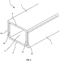
- a package 1 of drywall sections 2, 3 includes a first drywall section 2 and a second drywall section 3.
- Each of the drywall sections 2, 3 includes a joining portion 4 and opposing side arms 5a, 5b.
- the drywall sections 2, 3 are U channels and the opposing side arms 5a, 5b are substantially parallel to each other and perpendicular to the joining portion 4.
- the drywall sections 2, 3 are arranged, in particular stacked, to define a space 6 between the drywall sections 2, 3.
- a plurality of fasteners are contained within the space 6 between the drywall sections 2, 3, and a retainer is provided to hold the fasteners in the space 6.
- the fasteners are appropriate for attaching the drywall sections 2, 3 to a wall and/or each other and/or another structure for installing the drywall sections 2, 3. Once installed, drywall panels are attached to the drywall sections 2, 3.
- the fasteners may include any combination of screws, nails, nuts, bolts, anchors, plugs, or other fasteners needed to install the drywall sections 2, 3.
- the package 1 may include further pairs of drywall sections arranged in the same manner as the drywall sections 2, 3 illustrated in FIG. 1 .
- a package 1 may contain, for example, 2, 4, 5, or 10 pairs of drywall sections 2, 3 in the arrangement illustrated in FIG. 1 , the pairs of drywall sections 2, 3 being stacked and held together to form the package 1.
- the drywall rails 2, 3 may be held together by a strap or wrapping.
- the package 1 includes a container 7 that acts to retain the fasteners in the space 6 between the drywall sections 2, 3.
- the container 7 is in the form a box, in this example having a base 8 that holds the fasteners and a lid 9 that covers the base 8.
- the container 7 is sized to fit snugly in the space 6 between the drywall sections 2, 3.
- the container 7 may be sized slightly larger than the minimum size of the space 6 (i.e., when the drywall sections 2, 3 are in contact to define the smallest space), so that on packaging the drywall sections 2, 3 act to compress the container 7 and hold it in place.
- the container 7 may be sized to be smaller than the minim size of the space 6 so that the container 7 can slide within the space 6.
- the container 7 may be retained in the space 6 by adhesive, or by a wrap that at least partially covers the ends of the drywall sections 2, 3 to prevent the container 7 moving out of the space 6 until the package 1 is opened.
- the container 7 may comprise a plastics material, or a card material.
- the container 7 may be made of a recycled and/or recyclable material.
- the package 1 includes a container 10 that acts to retain the fasteners in the space 6 between the drywall sections 2, 3.
- the container 10 is in the form an open top box 11 that holds the fasteners in an internal space 12.
- the drawer 11 may include a handle 13 for pulling the drawer 11 out of the space 6.
- the drawer 11 is sized to fit snugly in the space 6 between the drywall sections 2, 3.
- the drawer 11 may be sized slightly larger than the minimum size of the space 6 (i.e., when the drywall sections 2, 3 are in contact to define the smallest space), so that on packaging the drywall sections 2, 3 act to compress the drawer 11 and hold it in place.
- the drawer 11 may be sized to be smaller than the minim size of the space 6 so that the drawer 11 can slide within the space 6.
- the drawer 11 may be retained in the space 6 by adhesive, or by a wrap that at least partially covers the ends of the drywall sections 2, 3 to prevent the drawer 11 moving out of the space 6 until the package 1 is opened.
- the drawer 11 may comprise a plastics material, or a card material.
- the drawer 11 may be made of a recycled and/or recyclable material.
- the package 1 includes a plug 14 that acts to retain the fasteners in the space 6 between the drywall sections 2, 3.
- the plug 14 comprises a plug portion 15 that fits in the space 6 and holds the fasteners in the space 6.
- the plug 14 may include a flange 16 attached to the plug portion 15, the flange 16 being larger than the plug portion 15 and the space 6 so that the flange 16 abuts the ends of the drywall sections 2, 3 when inserted in the space 6.
- the plug portion 15 is sized to fit snugly in the space 6 between the drywall sections 2, 3.
- the plug portion 15 may be sized slightly larger than the minimum size of the space 6 (i.e., when the drywall sections 2, 3 are in contact to define the smallest space), so that on packaging the drywall sections 2, 3 act to compress the plug portion 15 and hold the plug 14 in place.
- the plug portion 15 may be sized to be smaller than the minim size of the space 6, and the plug portion 15 may be retained in the space 6 by adhesive, or by a wrap that at least partially covers the ends of the drywall sections 2, 3 to prevent the plug 14 moving out of the space 6 until the package 1 is opened.
- a second plug 14 is provided at the opposite end of the drywall sections 2, 3 so that the fasteners are retained in the space 6 between the two plugs 14.
- the plug 14 may comprise a plastics material, or a card material.
- the plug 14 may be made of a recycled and/or recyclable material.
- the plug 14 of FIG. 4 may be used in combination with the container 7 of FIG. 2 or the container 10 of FIG. 3 to retain the container 7, 10 in the space 6.
- the fasteners may be loose within the space 6 and retained in the space 6 by the plugs 14.
- the fasteners may be linked to each other (e.g., using the linking member of FIG. 8 ) within the space 6, and the plugs 14 act to retain the fasteners within the space 6.
- FIGS. 5 to 8 the second drywall rail 3 is not shown, and the side arm 5b of the first drywall rail 2 is omitted for clarity.
- the package 1 includes retaining members 17a, 17b located in the space 6.
- the retaining members 17a, 17b are spaced apart and the fasteners are retained between the retaining members 17a, 17b.
- each of the retaining members 17a, 17b has a base portion 18 attached to the joining portion 4 of the drywall rail 2, and retaining portions 19 extending at least partially across the space 6 to retain the fasteners therebetween.
- the retaining members 17a, 17b may be attached to the drywall section 2 by adhesive.
- the retaining portions 19 of the retaining members 17a, 17b are sized so as to substantially block the space 6 and prevent passage of fasteners around the retaining portions 19, within the space 6.
- the retaining members 17a, 17b are sized and positioned to permit stacking of a second drywall section as shown in FIG. 1 .
- the retaining members 17a, 17b may be made from card, in particular recycled and/or recyclable card. Alternatively, the retaining members 17a, 17b may be made from metal, for example steel. In some examples the retaining members 17a, 17b are made from offcuts of the drywall sections 2, 3. If made from metal the retaining members 17a, 17b may be welded, in particular spot-welded, onto the drywall section 2.
- the installer When opening the package 1 of FIG. 5 the installer removes the top drywall section (3, see FIG. 1 ) to expose the fasteners retained between the retaining members 17a, 17b.
- FIG. 6 is similar and has retaining members 20 arranged to oppose each other within the space 6 and to retain fasteners between them.
- the retaining members 20 are formed by a partial cut-out 21 formed in the drywall section 2 and folded upwards about side 22. Accordingly, no additional materials are used to package the fasteners within the package 1.
- the retaining members 20 are sized so as to substantially block the space 6 and prevent passage of fasteners around the retaining members 20, within the space 6.
- the retaining members 20 are sized and positioned to permit stacking of a second drywall section as shown in FIG. 1 .
- FIG. 7 is similar and has retaining members 23 arranged to oppose each other within the space 6 and to retain fasteners between them.
- the retaining members 23 comprise blocks, for example blocks of card or wood, adhered to the drywall section 2 to retain fasteners between them.
- the retaining members 23 are sized so as to substantially block the space 6 and prevent passage of fasteners around the retaining members 23, within the space 6.
- the retaining members 20 are sized and positioned to permit stacking of a second drywall section as shown in FIG. 1 .
- the linking member 25 may be a card, plastics, or metal sheet having holes through which the fasteners 24 extend to removably attach the fasteners 24 to the linking member 25.
- the holes in the linking member 25 may be threaded, or sized so that the fasteners are a push-fit into the holes.
- the linking member 25 may include different size and shape holes for different fasteners.
- the linking member 25, together with the fasteners 24, may be retained in the space 6 by attaching the linking member 25 to the drywall section 2, for example by adhesive or by a fastener, in particular one of the fasteners 24 attached to the linking member 25.
- the attachment of the linking member 25 to the drywall section 2 is breakable or detachable so that the linking member 25 and fasteners 24 can be removed together for use during installation.
- linking member 25 and fasteners 24 may be retained in the space 6 by the container 7 of FIG. 2 , the drawer 11 of FIG. 3 , the plug 14 of FIG. 4 , or the retaining members 17a, 17b, 20, 23 of any of claims 5 to 7.
- Several linking members 25, each having a plurality of fasteners 24, may be provided.
- FIGS. 9A and 9B illustrate packages 1 of drywall sections 2, 3 comprising a plurality of pairs of drywall sections 2, 3, each pair being arranged as previously described.
- each pair of drywall sections 2, 3 is provided with a plurality of fasteners 26 retained in the space 6 between the drywall sections 2, 3.
- the fasteners 26 container the type and number of fasteners suitable for two drywall sections 2, 3.
- the installer is also provided with the appropriate fasteners 26.
- FIG. 9B only one pair of drywall sections 2a, 3a within the package 1 is provided with fasteners 27 retained in the space 6a between the drywall sections 2, 3.
- the spaces 6b of the other pairs of drywall sections 2b, 3b are not provided with fasteners.
- the fasteners 27 in this example comprise a sufficient number and type of fasteners for all of the drywall sections 2, 3 in the package 1.
- the package 1 includes ten drywall sections 2, 3 arrange in five pairs of drywall sections 2, 3. It will be appreciated that the package 1 may comprise any number of drywall sections 2, 3, in particular any even number of drywall sections 2, 3, such as two drywall sections 2, 3, four drywall sections 2, 3, ten drywall sections 2, 3, or twenty drywall sections 2, 3.
- a strap 28 is provided to hold the drywall sections 2, 3 together.
- a plurality of straps 28 may be provided, spaced along the length of the drywall sections 2, 3. Additional or alternative packaging may be provided, for example a wrap (partial or full), or container.
- each drywall section 2, 3 comprises a U channel section.
- FIGS. 10A to 10C illustrate alternative drywall sections that may be used in place of the U channel sections illustrated in FIGS. 1 to 9B . It will be appreciated that the alternative drywall sections shown in FIGS. 10A to 10C may be used with any of the other examples described herein.
- the package 1 includes drywall sections 28a, 28b that comprise C stud sections having a joining portion 29 extending between opposing side arms 30a, 30b, and inwardly protruding portions 31a, 31b extending from the opposing side arms 30a, 30b towards each other.
- the C stud sections can be stacked in an inverted pair arrangement similar to as described with reference to FIG. 1 to define a space 32 within which fasteners 33 are retained.
- the package 1 includes drywall sections 33a, 33b that comprise I stud sections having a web 34 extending between opposing flanges 35a, 35b.
- the I stud sections 33a, 33b can be stacked in a pair similar to as described with reference to FIG. 1 to define a space 36 within which fasteners 37 are retained.
- the package 1 includes drywall sections 38a, 38b that comprise J channels having a joining portion 39 extending between opposing side arms 40a, 40b.
- One of the opposing side arms 40b is shorter than the other opposing side arm 40a, forming a J profile.
- the J channel sections 38a, 38b can be stacked in an inverted pair arrangement similar to as described with reference to FIG. 1 to define a space 41 within which fasteners 42 are retained.
- fasteners can be retained in a space between two drywall sections, as described above, regardless of the profile of the drywall sections so long as they can be arranged to define a space therebetween.
Landscapes
- Engineering & Computer Science (AREA)
- Mechanical Engineering (AREA)
- Packages (AREA)
Abstract
The present invention provides a package (1) of drywall sections comprising a first drywall section (2) and a second drywall section (3). Each drywall section (2, 3) comprises opposing side arms (5a, 5b) and a joining portion (4) extending between the opposing side arms. The first and second drywall sections are arranged in a stacked configuration such that a space (6) is defined between the first and second drywall sections. The package of drywall sections further comprises a plurality of fasteners for installing the drywall sections. The plurality of fasteners are disposed within the space between the first and second drywall sections. The package also includes a retainer (7) configured to retain the plurality of fasteners within the space between the first and second drywall sections.
Description
- The present invention relates to a package of drywall sections, such channel sections or stud sections.
- Drywalls, otherwise known as dry lined walls, can be installed by first attaching one or more drywall sections to the existing wall and then attaching drywall panels to the drywall sections. Fasteners, such as nails, screws, anchors, and plugs, are used to attach the drywall sections to the wall and to each other.
- The present invention provides a package of drywall sections comprising a first drywall section and a second drywall section, each drywall section comprising opposing side arms and a joining portion extending between the opposing side arms, wherein the first and second drywall sections are arranged in a stacked configuration such that a space is defined between the first and second drywall sections; and wherein the package of drywall sections further comprises:
a plurality of fasteners for installing the drywall sections, the plurality of fasteners being disposed within the space between the first and second drywall sections; and a retainer configured to retain the plurality of fasteners within the space between the first and second drywall sections - In examples, the retainer comprises a container. The container may be received in the space between the first and second drywall rails, and the plurality of fasteners being disposed in the container.
- The container may be made from a recycled and/or recyclable material. In examples, the container comprises a card material.
- In examples, the container comprises a box having a height and a width that substantially a height and a width of the space between the first and second drywall sections. The box may therefore fit snugly in the space. The box may include a lid. The box may include a handle or knob for pulling the box out of the space to access the plurality of fasteners.
- In examples, the first and second drywall sections may be arranged such that an end of the first drywall section is substantially aligned with an end of the second drywall section. In such examples the retainer may comprise a plug having a plug portion that is inserted into the space between the first and second drywall sections at one end of the first and second drywall sections. The plug therefore acts to retain the plurality of fasteners or the container, for example a box, in the space between the first and second drywall sections.
- In examples, the plug may further comprise a flange that abuts the ends of the first and second drywall sections when the plug portion is inserted into the space between the first and second drywall sections at one end of the first and second drywall sections. The flange may be gripped to remove the plug from the drywall sections. In some examples, the package of drywall sections has a plug at each end of the first and second drywall sections.
- In examples, the retainer may comprise a retaining member extending across the space between the first and second drywall sections. The retaining member may extend partially across the space between the first and second drywall sections, or fully across the space between the first and second drywall sections. The retaining member may extend across the space between the first and second drywall sections to prevent any one of the plurality fasteners from passing around the retaining member within the space between the first and second drywall sections.
- In examples, the retainer comprises first and second retaining members extending across the space between the first and second drywall sections. The first and second retaining members may be spaced from each other and the plurality of fasteners being disposed between the first and second retaining members.
- In examples, the or each retaining member is formed by a folded portion of the first or second drywall section. Specifically, a square or rectangular portion of one of the drywall sections may be cut along three sides and folded upwards along the other side to form a retaining member. Advantageously, such a retaining member does not use additional material.
- In other examples, the or each retaining member is attached to the first and/or second drywall section, for example by adhesive. In examples, the or each retaining member may comprise metal, plastics, or card. The or each retaining member may comprise an offcut of a part of a drywall section.
- In examples, the retainer comprises a linking member to which each of the plurality of fasteners are joined. The linking member may be disposed in the space between the first and second drywall sections. The linking member may comprise a plastics, card, or wax member to which a plurality of fasteners are removably attached. The linking member, together with the fasteners, may be attached to at least one of the first and second drywall sections. In other examples, the linking member may be retained in the space between the first and second drywall sections by an additional retainer as described above.
- In examples, the plurality of fasteners comprises an appropriate number and type of fasteners for the first and second drywall sections. Accordingly, the installer is provided with the correct type and number of fasteners for each pair of drywall sections as they are unpackaged for installation.
- In other examples, the package of drywall sections may further comprise further drywall sections arranged in pairs, for example third and fourth drywall sections arranged in the same manner as the first and second drywall sections, and so on. In some examples, the package of drywall sections may comprise 10 drywall sections arranged in 5 pairs. In such examples, the plurality of fasteners contained within the space between the first and second drywall sections may comprise an appropriate number and type of fasteners for the first and second drywall sections and the further drywall sections. Therefore, the package of drywall sections may include all of the relevant fasteners in one location within a package of multiple drywall sections, which reduces the packaging materials needed to include these fasteners.
- In various examples each of the drywall sections may comprise a channel section or a stud section. In particular, each of the drywall sections may comprise a U channel section or a J channel section, or an I stud section or a C stud section. It will be appreciated that the invention defined in the claims is relevant to any drywall section that can be stacked in a pair such a space is defined between first and second drywall sections.
- Embodiments of the invention are further described hereinafter with reference to the accompanying drawings, in which:
-
FIG. 1 shows a partial view of a package of drywall sections, including first and second drywall sections. -
FIG. 2 shows an example container of fasteners for a package of drywall sections; -
FIG. 3 shows a further example container of fasteners for a package of drywall sections; -
FIG. 4 shows an example plug for retaining fasteners in a package of drywall sections; -
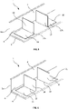
FIG. 5 shows example retaining members for retaining fasteners in a package of drywall sections; -
FIG. 6 shows further example retaining members for retaining fasteners in a package of drywall sections; -
FIG. 7 shows further example retaining members for retaining fasteners in a package of drywall sections; -
FIG. 8 shows an example linking member for joining together a plurality of fasteners in the package of drywall sections; -
FIGS. 9A and 9B show different configurations of packages of drywall sections; and -
FIGS. 10A to 10C show alternative drywall sections. - As shown in
FIG. 1 , apackage 1 ofdrywall sections first drywall section 2 and asecond drywall section 3. Each of thedrywall sections portion 4 andopposing side arms drywall sections opposing side arms portion 4. Within thepackage 1 thedrywall sections space 6 between thedrywall sections space 6 between thedrywall sections space 6. - The fasteners are appropriate for attaching the
drywall sections drywall sections drywall sections drywall sections - As described with reference to
FIGS. 9A and 9B , thepackage 1 may include further pairs of drywall sections arranged in the same manner as thedrywall sections FIG. 1 . In particular, apackage 1 may contain, for example, 2, 4, 5, or 10 pairs ofdrywall sections FIG. 1 , the pairs ofdrywall sections package 1. The drywall rails 2, 3 may be held together by a strap or wrapping. - In the example of
FIG. 2 thepackage 1 includes acontainer 7 that acts to retain the fasteners in thespace 6 between thedrywall sections container 7 is in the form a box, in this example having abase 8 that holds the fasteners and alid 9 that covers thebase 8. Thecontainer 7 is sized to fit snugly in thespace 6 between thedrywall sections - In some examples the
container 7 may be sized slightly larger than the minimum size of the space 6 (i.e., when thedrywall sections drywall sections container 7 and hold it in place. In other examples thecontainer 7 may be sized to be smaller than the minim size of thespace 6 so that thecontainer 7 can slide within thespace 6. Thecontainer 7 may be retained in thespace 6 by adhesive, or by a wrap that at least partially covers the ends of thedrywall sections container 7 moving out of thespace 6 until thepackage 1 is opened. - The
container 7 may comprise a plastics material, or a card material. Thecontainer 7 may be made of a recycled and/or recyclable material. - In the example of
FIG. 3 thepackage 1 includes acontainer 10 that acts to retain the fasteners in thespace 6 between thedrywall sections container 10 is in the form an opentop box 11 that holds the fasteners in aninternal space 12. Thedrawer 11 may include ahandle 13 for pulling thedrawer 11 out of thespace 6. Thedrawer 11 is sized to fit snugly in thespace 6 between thedrywall sections - In some examples the
drawer 11 may be sized slightly larger than the minimum size of the space 6 (i.e., when thedrywall sections drywall sections drawer 11 and hold it in place. In other examples thedrawer 11 may be sized to be smaller than the minim size of thespace 6 so that thedrawer 11 can slide within thespace 6. Thedrawer 11 may be retained in thespace 6 by adhesive, or by a wrap that at least partially covers the ends of thedrywall sections drawer 11 moving out of thespace 6 until thepackage 1 is opened. - The
drawer 11 may comprise a plastics material, or a card material. Thedrawer 11 may be made of a recycled and/or recyclable material. - In the example of
FIG. 4 thepackage 1 includes aplug 14 that acts to retain the fasteners in thespace 6 between thedrywall sections plug 14 comprises aplug portion 15 that fits in thespace 6 and holds the fasteners in thespace 6. Theplug 14 may include aflange 16 attached to theplug portion 15, theflange 16 being larger than theplug portion 15 and thespace 6 so that theflange 16 abuts the ends of thedrywall sections space 6. Theplug portion 15 is sized to fit snugly in thespace 6 between thedrywall sections - In some examples the
plug portion 15 may be sized slightly larger than the minimum size of the space 6 (i.e., when thedrywall sections drywall sections plug portion 15 and hold theplug 14 in place. In other examples theplug portion 15 may be sized to be smaller than the minim size of thespace 6, and theplug portion 15 may be retained in thespace 6 by adhesive, or by a wrap that at least partially covers the ends of thedrywall sections plug 14 moving out of thespace 6 until thepackage 1 is opened. - In examples, a
second plug 14 is provided at the opposite end of thedrywall sections space 6 between the two plugs 14. - The
plug 14 may comprise a plastics material, or a card material. Theplug 14 may be made of a recycled and/or recyclable material. - The
plug 14 ofFIG. 4 may be used in combination with thecontainer 7 ofFIG. 2 or thecontainer 10 ofFIG. 3 to retain thecontainer space 6. Alternatively, the fasteners may be loose within thespace 6 and retained in thespace 6 by theplugs 14. Alternatively, the fasteners may be linked to each other (e.g., using the linking member ofFIG. 8 ) within thespace 6, and theplugs 14 act to retain the fasteners within thespace 6. - In
FIGS. 5 to 8 thesecond drywall rail 3 is not shown, and theside arm 5b of thefirst drywall rail 2 is omitted for clarity. - In the example of
FIG. 5 thepackage 1 includes retainingmembers space 6. The retainingmembers members - As illustrated in
FIG. 5 , each of the retainingmembers base portion 18 attached to the joiningportion 4 of thedrywall rail 2, and retainingportions 19 extending at least partially across thespace 6 to retain the fasteners therebetween. The retainingmembers drywall section 2 by adhesive. The retainingportions 19 of the retainingmembers space 6 and prevent passage of fasteners around the retainingportions 19, within thespace 6. The retainingmembers FIG. 1 . - The retaining
members members members drywall sections members drywall section 2. - When opening the
package 1 ofFIG. 5 the installer removes the top drywall section (3, seeFIG. 1 ) to expose the fasteners retained between the retainingmembers - The example of
FIG. 6 is similar and has retainingmembers 20 arranged to oppose each other within thespace 6 and to retain fasteners between them. In this example, the retainingmembers 20 are formed by a partial cut-out 21 formed in thedrywall section 2 and folded upwards aboutside 22. Accordingly, no additional materials are used to package the fasteners within thepackage 1. - As with the example of
FIG. 5 , the retainingmembers 20 are sized so as to substantially block thespace 6 and prevent passage of fasteners around the retainingmembers 20, within thespace 6. The retainingmembers 20 are sized and positioned to permit stacking of a second drywall section as shown inFIG. 1 . - The example of
FIG. 7 is similar and has retainingmembers 23 arranged to oppose each other within thespace 6 and to retain fasteners between them. In this example, the retainingmembers 23 comprise blocks, for example blocks of card or wood, adhered to thedrywall section 2 to retain fasteners between them. - As with the example of
FIG. 5 , the retainingmembers 23 are sized so as to substantially block thespace 6 and prevent passage of fasteners around the retainingmembers 23, within thespace 6. The retainingmembers 20 are sized and positioned to permit stacking of a second drywall section as shown inFIG. 1 . - In the example of
FIG. 8 a plurality offasteners 24 are joined together by a linkingmember 25. The linkingmember 25 may be a card, plastics, or metal sheet having holes through which thefasteners 24 extend to removably attach thefasteners 24 to the linkingmember 25. In examples, the holes in the linkingmember 25 may be threaded, or sized so that the fasteners are a push-fit into the holes. The linkingmember 25 may include different size and shape holes for different fasteners. - The linking
member 25, together with thefasteners 24, may be retained in thespace 6 by attaching the linkingmember 25 to thedrywall section 2, for example by adhesive or by a fastener, in particular one of thefasteners 24 attached to the linkingmember 25. The attachment of the linkingmember 25 to thedrywall section 2 is breakable or detachable so that the linkingmember 25 andfasteners 24 can be removed together for use during installation. - In other examples, the linking
member 25 andfasteners 24 may be retained in thespace 6 by thecontainer 7 ofFIG. 2 , thedrawer 11 ofFIG. 3 , theplug 14 ofFIG. 4 , or the retainingmembers members 25, each having a plurality offasteners 24, may be provided. -
FIGS. 9A and 9B illustratepackages 1 ofdrywall sections drywall sections - In the example of
FIG. 9A each pair ofdrywall sections space 6 between thedrywall sections drywall sections drywall sections - In the example of
FIG. 9B only one pair ofdrywall sections package 1 is provided withfasteners 27 retained in thespace 6a between thedrywall sections spaces 6b of the other pairs ofdrywall sections fasteners 27 in this example comprise a sufficient number and type of fasteners for all of thedrywall sections package 1. - In the examples of
FIGS. 9A and 9B thepackage 1 includes tendrywall sections drywall sections package 1 may comprise any number ofdrywall sections drywall sections drywall sections drywall sections drywall sections drywall sections - A
strap 28 is provided to hold thedrywall sections straps 28 may be provided, spaced along the length of thedrywall sections - In the above examples each
drywall section FIGS. 10A to 10C illustrate alternative drywall sections that may be used in place of the U channel sections illustrated inFIGS. 1 to 9B . It will be appreciated that the alternative drywall sections shown inFIGS. 10A to 10C may be used with any of the other examples described herein. - In the example of
FIG. 10A thepackage 1 includesdrywall sections portion 29 extending between opposingside arms portions side arms FIG. 10A , the C stud sections can be stacked in an inverted pair arrangement similar to as described with reference toFIG. 1 to define aspace 32 within whichfasteners 33 are retained. - In the example of
FIG. 10B thepackage 1 includesdrywall sections web 34 extending between opposingflanges FIG. 10B , theI stud sections FIG. 1 to define a space 36 within which fasteners 37 are retained. - In the example of
FIG. 10C thepackage 1 includesdrywall sections portion 39 extending between opposingside arms side arms 40b is shorter than the other opposingside arm 40a, forming a J profile. As shown inFIG. 10C , theJ channel sections FIG. 1 to define a space 41 within which fasteners 42 are retained. - It will be appreciated that fasteners can be retained in a space between two drywall sections, as described above, regardless of the profile of the drywall sections so long as they can be arranged to define a space therebetween.
- Throughout the description and claims of this specification, the words "comprise" and "contain" and variations of them mean "including but not limited to", and they are not intended to (and do not) exclude other moieties, additives, components, integers or steps. Throughout the description and claims of this specification, the singular encompasses the plural unless the context otherwise requires. In particular, where the indefinite article is used, the specification is to be understood as contemplating plurality as well as singularity, unless the context requires otherwise.
- Features, integers, characteristics, or groups described in conjunction with a particular aspect, embodiment or example of the invention are to be understood to be applicable to any other aspect, embodiment or example described herein unless incompatible therewith. All of the features disclosed in this specification (including any accompanying claims, abstract and drawings) may be combined in any combination, except combinations where at least some of such features and/or steps are mutually exclusive. The invention is not restricted to the details of any foregoing embodiments. The invention extends to any novel one, or any novel combination, of the features disclosed in this specification (including any accompanying claims, abstract and drawings).
Claims (15)
- A package of drywall sections comprising a first drywall section and a second drywall section, each drywall section comprising opposing side arms and a joining portion extending between the opposing side arms, wherein the first and second drywall sections are arranged in a stacked configuration such that a space is defined between the first and second drywall sections; and wherein the package of drywall sections further comprises:a plurality of fasteners for installing the drywall sections, the plurality of fasteners being disposed within the space between the first and second drywall sections; anda retainer configured to retain the plurality of fasteners within the space between the first and second drywall sections
- The package of drywall sections of claim 1, wherein the retainer comprises a container, the container being received in the space between the first and second drywall rails and the plurality of fasteners being disposed in the container.
- The package of drywall sections of claim 2, wherein the container comprises a box having a height and a width that substantially a height and a width of the space between the first and second drywall sections.
- The package of drywall sections of any preceding claim, wherein the first and second drywall sections are arranged such that an end of the first drywall section is substantially aligned with an end of the second drywall section, and wherein the retainer comprises a plug having a plug portion that is inserted into the space between the first and second drywall sections at one end of the first and second drywall sections.
- The package of drywall sections of claim 4, wherein the plug further comprises a flange that abuts the ends of the first and second drywall sections when the plug portion is inserted into the space between the first and second drywall sections at one end of the first and second drywall sections.
- The package of drywall sections of claim 4 or claim 5, comprising a plug at each end of the first and second drywall sections.
- The package of drywall sections of any of claims 1 to 3, wherein the retainer comprises a retaining member extending across the space between the first and second drywall sections.
- The package of drywall sections of claim 7, wherein the retainer comprises first and second retaining members extending across the space between the first and second drywall sections, the first and second retaining members being spaced from each other and the plurality of fasteners being disposed between the first and second retaining members.
- The package of drywall sections of claim 7 or claim 8, wherein the or each retaining member is formed by a folded portion of the first or second drywall section.
- The package of drywall sections of claim 7 or claim 8, wherein the or each retaining member is attached to the first and/or second drywall section, for example by adhesive.
- The package of drywall sections of claim 1, wherein the retainer comprises a linking member to which each of the plurality of fasteners are joined, and wherein the linking member is disposed in the space between the first and second drywall sections.
- The package of drywall sections of claim 11, wherein the linking member is attached to at least one of the first and second drywall sections.
- The package of drywall sections of any preceding claim, wherein the plurality of fasteners comprises an appropriate number and type of fasteners for the first and second drywall sections.
- The package of drywall sections of any of claims 1 to 12, further comprising further drywall sections arranged in pairs, and wherein the plurality of fasteners contained within the space between the first and second drywall sections comprises an appropriate number and type of fasteners for the first and second drywall sections and the further drywall sections.
- The package of drywall sections of any preceding claim, wherein each of the drywall sections comprises a channel section or a stud section.
Priority Applications (1)
| Application Number | Priority Date | Filing Date | Title |
|---|---|---|---|
| EP20203296.7A EP3988468A1 (en) | 2020-10-22 | 2020-10-22 | Package of drywall sections |
Applications Claiming Priority (1)
| Application Number | Priority Date | Filing Date | Title |
|---|---|---|---|
| EP20203296.7A EP3988468A1 (en) | 2020-10-22 | 2020-10-22 | Package of drywall sections |
Publications (1)
| Publication Number | Publication Date |
|---|---|
| EP3988468A1 true EP3988468A1 (en) | 2022-04-27 |
Family
ID=73455497
Family Applications (1)
| Application Number | Title | Priority Date | Filing Date |
|---|---|---|---|
| EP20203296.7A Withdrawn EP3988468A1 (en) | 2020-10-22 | 2020-10-22 | Package of drywall sections |
Country Status (1)
| Country | Link |
|---|---|
| EP (1) | EP3988468A1 (en) |
Citations (5)
| Publication number | Priority date | Publication date | Assignee | Title |
|---|---|---|---|---|
| CA1040153A (en) * | 1976-04-02 | 1978-10-10 | Bulten-Kanthal Aktiebolag | Reinforced mating-bands fastener carrier strip |
| US20050034408A1 (en) * | 2003-07-30 | 2005-02-17 | Joseph Palumbo | Metal stud wall packaging system |
| WO2006105826A1 (en) * | 2005-04-07 | 2006-10-12 | Richter System Gmbh & Co. Kg | C-shaped profile |
| US7690167B2 (en) * | 2005-04-28 | 2010-04-06 | Antonic James P | Structural support framing assembly |
| US8782980B1 (en) * | 2012-11-09 | 2014-07-22 | Jose C. Fajardo | Protective device for covering the tip of a beam on which air conditioning equipment is installed |
-
2020
- 2020-10-22 EP EP20203296.7A patent/EP3988468A1/en not_active Withdrawn
Patent Citations (5)
| Publication number | Priority date | Publication date | Assignee | Title |
|---|---|---|---|---|
| CA1040153A (en) * | 1976-04-02 | 1978-10-10 | Bulten-Kanthal Aktiebolag | Reinforced mating-bands fastener carrier strip |
| US20050034408A1 (en) * | 2003-07-30 | 2005-02-17 | Joseph Palumbo | Metal stud wall packaging system |
| WO2006105826A1 (en) * | 2005-04-07 | 2006-10-12 | Richter System Gmbh & Co. Kg | C-shaped profile |
| US7690167B2 (en) * | 2005-04-28 | 2010-04-06 | Antonic James P | Structural support framing assembly |
| US8782980B1 (en) * | 2012-11-09 | 2014-07-22 | Jose C. Fajardo | Protective device for covering the tip of a beam on which air conditioning equipment is installed |
Similar Documents
| Publication | Publication Date | Title |
|---|---|---|
| US8079561B2 (en) | Universal metal stud clip | |
| US5612509A (en) | Stackable wire staple and raceway system | |
| US7503528B2 (en) | Cable mount | |
| US20240308724A1 (en) | Partitioned container | |
| US4817796A (en) | Packing box | |
| US9758273B2 (en) | High strength partition box assembly | |
| US4083464A (en) | Knockdown reusable container | |
| US20080236859A1 (en) | Protective device plate for an electrical box | |
| US6948680B2 (en) | Device and method for storing electric cable and electric cable components | |
| US4214668A (en) | Electrical box and mounting bracket assembly | |
| CA2618907A1 (en) | Utility portal for wall construction | |
| US20050092509A1 (en) | Gangable electrical box | |
| EP0302638B1 (en) | Container with means for securing to a pallet | |
| AU2014298756A1 (en) | Blank, method for producing an external packaging unit, and packaging system | |
| CA2211040A1 (en) | Washer pack | |
| WO1995004660A1 (en) | A file stiffener | |
| US4955825A (en) | Electrical fixture | |
| US6669082B1 (en) | Compression supporting package divider set | |
| KR20150049610A (en) | Angle for packing box | |
| US20200140142A1 (en) | Flexible dynamic packaging of product entities | |
| US6203235B1 (en) | Method and apparatus for securing a crate fastener to a crate panel | |
| US6367627B2 (en) | Packaging box for folded ridge cover roofing | |
| US6511244B1 (en) | Binder | |
| US5366083A (en) | Packing and storing receptacle, particularly for knitting machine needles | |
| US20020179550A1 (en) | Rack with divided base plate for stacking flat articles |
Legal Events
| Date | Code | Title | Description |
|---|---|---|---|
| PUAI | Public reference made under article 153(3) epc to a published international application that has entered the european phase |
Free format text: ORIGINAL CODE: 0009012 |
|
| STAA | Information on the status of an ep patent application or granted ep patent |
Free format text: STATUS: THE APPLICATION HAS BEEN PUBLISHED |
|
| AK | Designated contracting states |
Kind code of ref document: A1 Designated state(s): AL AT BE BG CH CY CZ DE DK EE ES FI FR GB GR HR HU IE IS IT LI LT LU LV MC MK MT NL NO PL PT RO RS SE SI SK SM TR |
|
| STAA | Information on the status of an ep patent application or granted ep patent |
Free format text: STATUS: THE APPLICATION IS DEEMED TO BE WITHDRAWN |
|
| 18D | Application deemed to be withdrawn |
Effective date: 20221028 |