EP3988461A1 - Mechanism for label size selection - Google Patents
Mechanism for label size selection Download PDFInfo
- Publication number
- EP3988461A1 EP3988461A1 EP21204190.9A EP21204190A EP3988461A1 EP 3988461 A1 EP3988461 A1 EP 3988461A1 EP 21204190 A EP21204190 A EP 21204190A EP 3988461 A1 EP3988461 A1 EP 3988461A1
- Authority
- EP
- European Patent Office
- Prior art keywords
- index
- peel
- arm
- bearing
- plate
- Prior art date
- Legal status (The legal status is an assumption and is not a legal conclusion. Google has not performed a legal analysis and makes no representation as to the accuracy of the status listed.)
- Granted
Links
Images





Classifications
-
- B—PERFORMING OPERATIONS; TRANSPORTING
- B65—CONVEYING; PACKING; STORING; HANDLING THIN OR FILAMENTARY MATERIAL
- B65C—LABELLING OR TAGGING MACHINES, APPARATUS, OR PROCESSES
- B65C3/00—Labelling other than flat surfaces
- B65C3/02—Affixing labels to elongated objects, e.g. wires, cables, bars, tubes
-
- B—PERFORMING OPERATIONS; TRANSPORTING
- B65—CONVEYING; PACKING; STORING; HANDLING THIN OR FILAMENTARY MATERIAL
- B65C—LABELLING OR TAGGING MACHINES, APPARATUS, OR PROCESSES
- B65C9/00—Details of labelling machines or apparatus
- B65C9/40—Controls; Safety devices
- B65C9/42—Label feed control
-
- B—PERFORMING OPERATIONS; TRANSPORTING
- B65—CONVEYING; PACKING; STORING; HANDLING THIN OR FILAMENTARY MATERIAL
- B65C—LABELLING OR TAGGING MACHINES, APPARATUS, OR PROCESSES
- B65C9/00—Details of labelling machines or apparatus
- B65C9/0006—Removing backing sheets
-
- B—PERFORMING OPERATIONS; TRANSPORTING
- B65—CONVEYING; PACKING; STORING; HANDLING THIN OR FILAMENTARY MATERIAL
- B65C—LABELLING OR TAGGING MACHINES, APPARATUS, OR PROCESSES
- B65C9/00—Details of labelling machines or apparatus
- B65C9/08—Label feeding
- B65C9/18—Label feeding from strips, e.g. from rolls
-
- B—PERFORMING OPERATIONS; TRANSPORTING
- B65—CONVEYING; PACKING; STORING; HANDLING THIN OR FILAMENTARY MATERIAL
- B65C—LABELLING OR TAGGING MACHINES, APPARATUS, OR PROCESSES
- B65C9/00—Details of labelling machines or apparatus
- B65C9/08—Label feeding
- B65C9/18—Label feeding from strips, e.g. from rolls
- B65C9/1865—Label feeding from strips, e.g. from rolls the labels adhering on a backing strip
-
- B—PERFORMING OPERATIONS; TRANSPORTING
- B65—CONVEYING; PACKING; STORING; HANDLING THIN OR FILAMENTARY MATERIAL
- B65H—HANDLING THIN OR FILAMENTARY MATERIAL, e.g. SHEETS, WEBS, CABLES
- B65H35/00—Delivering articles from cutting or line-perforating machines; Article or web delivery apparatus incorporating cutting or line-perforating devices, e.g. adhesive tape dispensers
- B65H35/0006—Article or web delivery apparatus incorporating cutting or line-perforating devices
- B65H35/006—Article or web delivery apparatus incorporating cutting or line-perforating devices with means for delivering a predetermined length of tape
- B65H35/0066—Article or web delivery apparatus incorporating cutting or line-perforating devices with means for delivering a predetermined length of tape this length being adjustable
-
- B—PERFORMING OPERATIONS; TRANSPORTING
- B65—CONVEYING; PACKING; STORING; HANDLING THIN OR FILAMENTARY MATERIAL
- B65C—LABELLING OR TAGGING MACHINES, APPARATUS, OR PROCESSES
- B65C9/00—Details of labelling machines or apparatus
- B65C9/0006—Removing backing sheets
- B65C2009/0009—Removing backing sheets by means of a peeling tip
-
- B—PERFORMING OPERATIONS; TRANSPORTING
- B65—CONVEYING; PACKING; STORING; HANDLING THIN OR FILAMENTARY MATERIAL
- B65H—HANDLING THIN OR FILAMENTARY MATERIAL, e.g. SHEETS, WEBS, CABLES
- B65H2701/00—Handled material; Storage means
- B65H2701/10—Handled articles or webs
- B65H2701/19—Specific article or web
- B65H2701/194—Web supporting regularly spaced adhesive articles, e.g. labels, rubber articles, labels or stamps
-
- H—ELECTRICITY
- H01—ELECTRIC ELEMENTS
- H01B—CABLES; CONDUCTORS; INSULATORS; SELECTION OF MATERIALS FOR THEIR CONDUCTIVE, INSULATING OR DIELECTRIC PROPERTIES
- H01B13/00—Apparatus or processes specially adapted for manufacturing conductors or cables
- H01B13/34—Apparatus or processes specially adapted for manufacturing conductors or cables for marking conductors or cables
- H01B13/344—Apparatus or processes specially adapted for manufacturing conductors or cables for marking conductors or cables by applying sleeves, ferrules, tags, clips, labels or short length strips
Definitions
- the present invention relates to a benchtop label applicator assembly, and more particularly to a mechanism for label size selection for the benchtop label applicator assembly.
- Label applicators have been designed to wrap labels around a cable without spinning the cable along the longitudinal axis.
- the label applicators can include an internal printer that prepare labels for wire, cables or other elongated objects of varying diameters.
- label applicators can apply pre-printed labels to the wires, cables or other elongated objects of varying diameters.
- the pre-printed labels are presented on spools that are attached to the label applicator. When it is desirable to apply a different size label, the pre-printed label spool is replaced with a pre-printed label spool of the desired size labels.
- the present invention is directed to a mechanism designed to select a label size in a label applicator.
- the mechanism includes an index plate with an index arm pivotably mounted to the index plate.
- a wedge carrier is mounted to the index plate.
- the wedge carrier includes guide rollers and a peel blade that from a peel wedge which dictates a label path for the label in the label applicator. The movement of the index plate by the index arm linearly moves the wedge carrier and attached guide rollers and peel blade thereby adjusting the label path in the label applicator.
- the present invention is directed towards a mechanism that allows an operator to select the label size they will be working with and mechanical adjustments to the label applicator to accommodate the specific label size.
- FIG. 1 illustrates a bench top label applicator 20 with an electrical enclosure 22 on a base plate 26, an applicator head assembly 28 that includes a label wrapping system 30, a spindle 32 for receiving a spool of pre-printed labels, and a label liner rewind 34.
- a selectable peel and present subassembly 50 is mounted to the vertical plate 24 of the electrical enclosure 22 and positioned above the applicator head assembly 28.
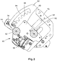
- FIGS. 2-4 illustrate a side view of the selectable peel and present subassembly 50 of the present invention.
- the selectable peel and present subassembly 50 is easily accessible by the operator.
- the selectable peel and present subassembly 50 is designed to adjust the label path in the label applicator 20 to accommodate various label sizes to be affixed to cables.
- the selectable peel and present subassembly 50 includes the components that make up a peel wedge for the present invention.
- the peel wedge is the shape of the media or label path as viewed from the side of the label applicator 20.
- the location of the peel wedge with respect to the applicator head dictates the size or length of the label that is going to be applied to the cables.
- the shape of the peel wedge is also crucial to consistent peeling of the label that is applied to the cables.
- the peel wedge is formed by two guides rollers 62 and the peel blade 68, which is under the blade carrier 66.
- the components that form the peel wedge are attached to the wedge carrier 60.
- the wedge carrier 60 is directly translated along the index slot 92 ( FIGS. 9-10 ) in the index plate 90 by the operator through the index arm 74.
- the index plate 90 includes an index pattern 94 with a number of slots 96 that receive an index bolt 80 of the index arm 74.
- Each slot 96 defines the distance the peel wedge is located from the applicator head 28.
- the operator can move the index arm 74 to be positioned in one of several slots 96 in the index pattern 94.
- FIG. 3 illustrates the index arm 74 and wedge carrier 60 in a forward most position
- FIG. 4 illustrates the index arm 74 and wedge carrier 60 in a back position.
- the peel wedge components are moved to a proper distance away from the applicator head 28 to accommodate the specific label size that the operator wants to apply to the cable.
- FIGS. 5-11 further illustrate the selectable peel and present subassembly 50.
- the right side of the selectable peel and present subassembly 50 includes an index spacer 52, a wedge carrier 60, a label presence sensor and housing 64, a blade carrier 66 and an emitter arm 72.
- FIG. 6 illustrates an exploded view of the blade carrier 66 that extends from the wedge carrier 60.
- the blade carrier 66 includes a peel blade 68 that is secured to the bottom of the blade carrier 66 via fasteners 70.
- FIGS. 7 and 8 illustrate the index arm 74 that is secured to the selectable peel and present subassembly 50.
- the index arm 74 enables the operator to engage the wedge carrier 60.
- the index arm 74 includes an indexer 76, a spring 78, an index bolt 80 secured to the indexer 76, a pivot bearing 82 with a pivot bolt 86 located in a slot 84 in the index arm 74, and an index arm bushing 88.
- the indexer 76 is spring biased so that once the operator releases the indexer 76, the spring 78 forces the indexer 76 back to its initial position.
- FIG. 3 illustrates the indexer 76 in the forward most position
- FIG. 4 illustrates the indexer 76 in a back position.
- the pivot bearing 82 translates the motion of the index arm 74 to the wedge carrier 60 and attached peel wedge components.
- the pivot bearing 82 rides linearly in a slot 84 in the index arm 74.
- a pivot bolt 86 extends through the pivot bearing 82 and affixes into the wedge carrier 60.
- the pivot bearing 82 moves rotationally around the pivot bolt 86, and relative to the wedge carrier 60.
- Leverage to move the wedge carrier 60 is created by the index arm's 74 movement around the index arm bushing 88, which mounts to the pivot shaft 54 (see FIG. 9 ) on the index spacer 52.
- the index arm 74 is retained on the selectable peel and present subassembly 50 by the pivot bearing bolt 86 and a nut on the pivot shaft 54.
- FIG. 9 illustrates the left side of the selectable peel and present subassembly 50 without the index arm 74 installed.
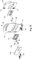
- FIG. 10 is an exploded view of the selectable peel and present subassembly 50 without the index arm 74 installed.
- the wedge carrier 60 is attached to the index plate 90 via nylon plastic bearings 100, 102. A portion in a first bearing 100 fits into the index slot 92 in the index plate 90, which forces the wedge carrier 60 to follow a linear motion, despite the arcing motion of the index arm 74.
- a second bearing 102 is mounted with compression springs 104 between the second bearing 102 and the backing plate 106 to apply a compressive force to the selectable peel and present subassembly 50 so that the second bearing 102 is drawn against the index plate 90.
- Compression bolts 108 reach through all of the components and thread into the wedge carrier 60, to hold the subassembly 50 together.
- a pair of limit bearings 110 are positioned on the wedge carrier 60. The limit bearings 110 reduce undesirable deflection of the subassembly 50 around the compression springs 104 when web tension is applied through the peel blade 68 by changing the point where the subassembly 50 would pivot and involving all compression springs 104 in resisting deflection of the subassembly 50.
- FIG. 11 illustrates a right perspective view of the selectable peel and present subassembly 50.
- the index arm 74 is secured to the index plate 90 via the pivot bearing 82 and the bearing assembly.
- An indexer position sensor 112 is attached to the index arm 74.
- the sensor 112 is a rotary potentiometer that allows the label applicator 20 to determine the position of the index arm 74, thus reducing label selection errors.
- the indexer position sensor 112 is fixed against rotation to the index arm 74 and keyed through its center with a sleeve to a mating feature in the pivot shaft 54 thereby ensuring consistent orientation.
Landscapes
- Labeling Devices (AREA)
- Unwinding Webs (AREA)
- Adhesive Tape Dispensing Devices (AREA)
Abstract
Description
- The present invention relates to a benchtop label applicator assembly, and more particularly to a mechanism for label size selection for the benchtop label applicator assembly.
- Label applicators have been designed to wrap labels around a cable without spinning the cable along the longitudinal axis. The label applicators can include an internal printer that prepare labels for wire, cables or other elongated objects of varying diameters. Alternatively, label applicators can apply pre-printed labels to the wires, cables or other elongated objects of varying diameters. The pre-printed labels are presented on spools that are attached to the label applicator. When it is desirable to apply a different size label, the pre-printed label spool is replaced with a pre-printed label spool of the desired size labels.
- Thus, it would be desirable to provide a label applicator that allows repeatable changeover between label sizes without multiple pre-printed label spools or additional tooling.
- The present invention is directed to a mechanism designed to select a label size in a label applicator. The mechanism includes an index plate with an index arm pivotably mounted to the index plate. A wedge carrier is mounted to the index plate. The wedge carrier includes guide rollers and a peel blade that from a peel wedge which dictates a label path for the label in the label applicator. The movement of the index plate by the index arm linearly moves the wedge carrier and attached guide rollers and peel blade thereby adjusting the label path in the label applicator.
-
-
FIG. 1 is a perspective view of the benchtop label applicator with the selectable peel and present mechanism of the present invention. -
FIG. 2 is a right side view of the selectable peel and present mechanism ofFIG. 1 . -
FIG. 3 is a right side view of the selectable peel and present mechanism ofFIG. 1 with the index arm in a forward position. -
FIG. 4 is a right side view of the selectable peel and present mechanism ofFIG. 1 with the index arm in a back position. -
FIG. 5 is a right side perspective view of the selectable peel and present mechanism ofFIG. 1 . -
FIG. 6 is an exploded view of the blade carrier of the selectable peel and present mechanism ofFIG. 5 . -
FIG. 7 is a left side perspective view of the index arm of the selectable peel and present mechanism ofFIG. 5 . -
FIG. 8 is a right side perspective view of the index arm of the selectable peel and present mechanism ofFIG. 5 . -
FIG. 9 is a left side perspective view of the index plate and wedge carrier of the selectable peel and present mechanism ofFIG. 5 . -
FIG. 10 is an exploded perspective view of the index plate and the wedge carrier ofFIG. 9 . -
FIG. 11 is a left side perspective view of the selectable peel and present mechanism ofFIG. 1 . - The present invention is directed towards a mechanism that allows an operator to select the label size they will be working with and mechanical adjustments to the label applicator to accommodate the specific label size.
-
FIG. 1 illustrates a benchtop label applicator 20 with anelectrical enclosure 22 on abase plate 26, anapplicator head assembly 28 that includes alabel wrapping system 30, aspindle 32 for receiving a spool of pre-printed labels, and a label liner rewind 34. A selectable peel andpresent subassembly 50 is mounted to thevertical plate 24 of theelectrical enclosure 22 and positioned above theapplicator head assembly 28. -
FIGS. 2-4 illustrate a side view of the selectable peel andpresent subassembly 50 of the present invention. The selectable peel andpresent subassembly 50 is easily accessible by the operator. The selectable peel andpresent subassembly 50 is designed to adjust the label path in thelabel applicator 20 to accommodate various label sizes to be affixed to cables. The selectable peel andpresent subassembly 50 includes the components that make up a peel wedge for the present invention. The peel wedge is the shape of the media or label path as viewed from the side of thelabel applicator 20. The location of the peel wedge with respect to the applicator head dictates the size or length of the label that is going to be applied to the cables. The shape of the peel wedge is also crucial to consistent peeling of the label that is applied to the cables. - The peel wedge is formed by two
guides rollers 62 and the peel blade 68, which is under theblade carrier 66. The components that form the peel wedge are attached to thewedge carrier 60. As described below, thewedge carrier 60 is directly translated along the index slot 92 (FIGS. 9-10 ) in theindex plate 90 by the operator through theindex arm 74. - As illustrated in
FIGS. 3 and4 , theindex plate 90 includes anindex pattern 94 with a number ofslots 96 that receive anindex bolt 80 of theindex arm 74. Eachslot 96 defines the distance the peel wedge is located from theapplicator head 28. The operator can move theindex arm 74 to be positioned in one ofseveral slots 96 in theindex pattern 94.FIG. 3 illustrates theindex arm 74 andwedge carrier 60 in a forward most position andFIG. 4 illustrates theindex arm 74 andwedge carrier 60 in a back position. When the operator moves theindex arm 74, the peel wedge components are moved to a proper distance away from theapplicator head 28 to accommodate the specific label size that the operator wants to apply to the cable. -
FIGS. 5-11 further illustrate the selectable peel andpresent subassembly 50. As illustrated inFIG. 5 , the right side of the selectable peel andpresent subassembly 50 includes anindex spacer 52, awedge carrier 60, a label presence sensor andhousing 64, ablade carrier 66 and anemitter arm 72. Theguide rollers 62 that extend from thewedge carrier 60, as illustrated inFIGS. 1-4 , have been omitted for clarity. -
FIG. 6 illustrates an exploded view of theblade carrier 66 that extends from thewedge carrier 60. Theblade carrier 66 includes a peel blade 68 that is secured to the bottom of theblade carrier 66 viafasteners 70. -
FIGS. 7 and8 illustrate theindex arm 74 that is secured to the selectable peel andpresent subassembly 50. As described above, theindex arm 74 enables the operator to engage thewedge carrier 60. Theindex arm 74 includes anindexer 76, aspring 78, anindex bolt 80 secured to theindexer 76, a pivot bearing 82 with apivot bolt 86 located in aslot 84 in theindex arm 74, and an index arm bushing 88. Theindexer 76 is spring biased so that once the operator releases theindexer 76, thespring 78 forces theindexer 76 back to its initial position. - To change the position of the
index arm 74 with respect to theslots 96 in theindex plate 90, the operator lifts theindexer 76 and attachedindex bolt 80 out of thecurrent slot 96 of theindex pattern 94 in theindex plate 90. While still holding theindexer 76 up, the operator can move theindexer 76 andindex arm 74 to another position along theindex plate 90. As discussed above,FIG. 3 illustrates theindexer 76 in the forward most position andFIG. 4 illustrates theindexer 76 in a back position. When the operator releases theindexer 76, thespring 78 returns theindexer 76 down and combined with the shape of theslots 96 in theindex plate 90, holds theindex bolt 80 into position within one of theslots 96. - The pivot bearing 82 translates the motion of the
index arm 74 to thewedge carrier 60 and attached peel wedge components. The pivot bearing 82 rides linearly in aslot 84 in theindex arm 74. Apivot bolt 86 extends through the pivot bearing 82 and affixes into thewedge carrier 60. The pivot bearing 82 moves rotationally around thepivot bolt 86, and relative to thewedge carrier 60. - Leverage to move the
wedge carrier 60 is created by the index arm's 74 movement around the index arm bushing 88, which mounts to the pivot shaft 54 (seeFIG. 9 ) on theindex spacer 52. Theindex arm 74 is retained on the selectable peel andpresent subassembly 50 by thepivot bearing bolt 86 and a nut on thepivot shaft 54. -
FIG. 9 illustrates the left side of the selectable peel andpresent subassembly 50 without theindex arm 74 installed.FIG. 10 is an exploded view of the selectable peel andpresent subassembly 50 without theindex arm 74 installed. Thewedge carrier 60 is attached to theindex plate 90 via nylonplastic bearings first bearing 100 fits into theindex slot 92 in theindex plate 90, which forces thewedge carrier 60 to follow a linear motion, despite the arcing motion of theindex arm 74. Asecond bearing 102 is mounted with compression springs 104 between thesecond bearing 102 and thebacking plate 106 to apply a compressive force to the selectable peel andpresent subassembly 50 so that thesecond bearing 102 is drawn against theindex plate 90. This reduces free movement of thesubassembly 50 that would occur through a tolerance stackup.Compression bolts 108 reach through all of the components and thread into thewedge carrier 60, to hold thesubassembly 50 together. A pair oflimit bearings 110 are positioned on thewedge carrier 60. Thelimit bearings 110 reduce undesirable deflection of thesubassembly 50 around the compression springs 104 when web tension is applied through the peel blade 68 by changing the point where thesubassembly 50 would pivot and involving all compression springs 104 in resisting deflection of thesubassembly 50. -
FIG. 11 illustrates a right perspective view of the selectable peel andpresent subassembly 50. Theindex arm 74 is secured to theindex plate 90 via the pivot bearing 82 and the bearing assembly. Anindexer position sensor 112 is attached to theindex arm 74. Thesensor 112 is a rotary potentiometer that allows thelabel applicator 20 to determine the position of theindex arm 74, thus reducing label selection errors. Theindexer position sensor 112 is fixed against rotation to theindex arm 74 and keyed through its center with a sleeve to a mating feature in thepivot shaft 54 thereby ensuring consistent orientation. - Furthermore, while the particular preferred embodiments of the present invention have been shown and described, it will be obvious to those skilled in the art that changes and modifications may be made without departing from the teaching of the invention. The matter set forth in the foregoing description and accompanying drawings is offered by way of illustration only and not as limitation. The actual scope of the invention is intended to be defined in the following claims when viewed in their proper perspective based on the prior art.
- The following clauses are disclosed herein:
- 1. A mechanism for label size selection on a label applicator, the mechanism comprising:
- an index plate with an index arm pivotably mounted to the index plate; and
- a wedge carrier mounted to the index plate, wherein the wedge carrier dictates a label path;
- whereby movement of the index plate by the index arm linearly moves the wedge carrier thereby adjusting the label path in the label applicator.
- 2. The mechanism of clause 1, wherein the index plate having an index pattern with a number of slots for receiving and maintaining the index arm.
- 3. The mechanism of clause 2, wherein the index arm having a spring biased indexer extending from one side of the index arm; and an index bolt secured to the indexer and extending from the index arm from a side opposite the indexer; whereby the index bolt extends through one of the number of slots in the index pattern to maintain the index arm in a desired position.
- 4. The mechanism of clause 1, wherein the index arm having a slot and a pivot bearing positioned within the slot, a pivot bolt extends through the pivot bearing and affixes to the wedge carrier, wherein the pivot bearing translates motion of the index arm to the wedge carrier.
- 5. The mechanism of clause 1, wherein the index arm further comprising an index arm bushing adapted to be mounted to a pivot shaft extending from an index spacer mounted to the index plate.
- 6. The mechanism of clause 1, wherein the wedge carrier having guide rollers and a blade carrier housing a peel blade.
- 7. The mechanism of clause 6, wherein the guide rollers and the peel blade define a peel wedge that forms the label path in the label applicator.
- 8. The mechanism of clause 1, further comprising a label presence sensor and housing mounted to the wedge carrier.
- 9. The mechanism of clause 1, wherein an index spacer is mounted to the index plate, the index spacer having a pivot shaft adapted to receive the index arm.
- 10. The mechanism of clause 1, wherein the wedge carrier is secured to the index plate by a first bearing and a second bearing, the first bearing is positioned in an index slot in the index plate, the second bearing is mounted to the first bearing that extends through the index slot.
- 11. The mechanism of clause 10, further comprising compression springs and a backing plate mounted to the second bearing to draw the second bearing against the index plate.
- 12. A selectable peel and present subassembly mounted to a label applicator, the selectable peel and present subassembly comprising:
- an index plate with an index arm pivotably mounted to the index plate; and
- a wedge carrier mounted to the index plate, the wedge carrier houses components forming a peel wedge, wherein the components of the peel wedge are adapted to be positioned a proper distance away from an applicator head on the label applicator;
- whereby the selectable peel and present assembly adjusts a label path in the label applicator for accommodating various label sizes to be affixed to cables.
- 13. The selectable peel and present subassembly of clause 12, wherein the index plate having an index pattern with a number of slots for receiving and maintaining the index arm.
- 14. The selectable peel and present subassembly of clause 13, wherein the index arm having a spring biased indexer extending from one side of the index arm; and an index bolt secured to the indexer and extending from the index arm from a side opposite the indexer; whereby the index bolt extends through one of the number of slots in the index pattern to maintain the index arm in a desired position.
- 15. The selectable peel and present subassembly of clause 12, wherein the index arm having a slot and a pivot bearing positioned within the slot, a pivot bolt extends through the pivot bearing and affixes to the wedge carrier, wherein the pivot bearing translates motion of the index arm to the wedge carrier.
- 16. The selectable peel and present subassembly of clause 12, wherein the index arm further comprising an index arm bushing adapted to be mounted to a pivot shaft extending from an index spacer mounted to the index plate.
- 17. The selectable peel and present subassembly of clause 12, wherein the wedge carrier has guide rollers and a peel blade housed in a blade carrier to define the peel wedge; whereby the guide rollers and the peel blade form the label path in the label applicator.
- 18. The selectable peel and present subassembly of clause 12, wherein an index spacer is mounted to the index plate, the index spacer having a pivot shaft adapted to receive the index arm.
- 19. The selectable peel and present subassembly of clause 12, wherein the wedge carrier is secured to the index plate by a first bearing and a second bearing, the first bearing is positioned in an index slot in the index plate, the second bearing is mounted to the first bearing that extends through the index slot.
- 20. The selectable peel and present subassembly of clause 19, further comprising compression springs and a backing plate mounted to the second bearing to draw the second bearing against the index plate.
Claims (15)
- A mechanism for label size selection on a label applicator, the mechanism comprising:an index plate with an index arm pivotably mounted to the index plate; anda wedge carrier mounted to the index plate, wherein the wedge carrier dictates a label path;whereby movement of the index plate by the index arm linearly moves the wedge carrier thereby adjusting the label path in the label applicator.
- The mechanism of claim 1, wherein the index plate having an index pattern with a number of slots for receiving and maintaining the index arm;
and optionally wherein the index arm having a spring biased indexer extending from one side of the index arm; and an index bolt secured to the indexer and extending from the index arm from a side opposite the indexer; whereby the index bolt extends through one of the number of slots in the index pattern to maintain the index arm in a desired position. - The mechanism of claim 1, wherein the index arm having a slot and a pivot bearing positioned within the slot, a pivot bolt extends through the pivot bearing and affixes to the wedge carrier, wherein the pivot bearing translates motion of the index arm to the wedge carrier.
- The mechanism of claim 1, wherein the index arm further comprising an index arm bushing adapted to be mounted to a pivot shaft extending from an index spacer mounted to the index plate.
- The mechanism of claim 1, wherein the wedge carrier having guide rollers and a blade carrier housing a peel blade;
and optionally wherein the guide rollers and the peel blade define a peel wedge that forms the label path in the label applicator. - The mechanism of claim 1, further comprising a label presence sensor and housing mounted to the wedge carrier.
- The mechanism of claim 1, wherein an index spacer is mounted to the index plate, the index spacer having a pivot shaft adapted to receive the index arm.
- The mechanism of claim 1, wherein the wedge carrier is secured to the index plate by a first bearing and a second bearing, the first bearing is positioned in an index slot in the index plate, the second bearing is mounted to the first bearing that extends through the index slot;
and optionally further comprising compression springs and a backing plate mounted to the second bearing to draw the second bearing against the index plate. - A selectable peel and present subassembly mounted to a label applicator, the selectable peel and present subassembly comprising:an index plate with an index arm pivotably mounted to the index plate; anda wedge carrier mounted to the index plate, the wedge carrier houses components forming a peel wedge, wherein the components of the peel wedge are adapted to be positioned a proper distance away from an applicator head on the label applicator;whereby the selectable peel and present assembly adjusts a label path in the label applicator for accommodating various label sizes to be affixed to cables.
- The selectable peel and present subassembly of claim 12, wherein the index plate having an index pattern with a number of slots for receiving and maintaining the index arm;
and optionally wherein the index arm having a spring biased indexer extending from one side of the index arm; and an index bolt secured to the indexer and extending from the index arm from a side opposite the indexer; whereby the index bolt extends through one of the number of slots in the index pattern to maintain the index arm in a desired position. - The selectable peel and present subassembly of claim 12, wherein the index arm having a slot and a pivot bearing positioned within the slot, a pivot bolt extends through the pivot bearing and affixes to the wedge carrier, wherein the pivot bearing translates motion of the index arm to the wedge carrier.
- The selectable peel and present subassembly of claim 12, wherein the index arm further comprising an index arm bushing adapted to be mounted to a pivot shaft extending from an index spacer mounted to the index plate.
- The selectable peel and present subassembly of claim 12, wherein the wedge carrier has guide rollers and a peel blade housed in a blade carrier to define the peel wedge; whereby the guide rollers and the peel blade form the label path in the label applicator.
- The selectable peel and present subassembly of claim 12, wherein an index spacer is mounted to the index plate, the index spacer having a pivot shaft adapted to receive the index arm.
- The selectable peel and present subassembly of claim 12, wherein the wedge carrier is secured to the index plate by a first bearing and a second bearing, the first bearing is positioned in an index slot in the index plate, the second bearing is mounted to the first bearing that extends through the index slot;
and optionally further comprising compression springs and a backing plate mounted to the second bearing to draw the second bearing against the index plate.
Applications Claiming Priority (2)
| Application Number | Priority Date | Filing Date | Title |
|---|---|---|---|
| US202063105497P | 2020-10-26 | 2020-10-26 | |
| US17/498,913 US11673704B2 (en) | 2020-10-26 | 2021-10-12 | Mechanism for label size selection |
Publications (2)
| Publication Number | Publication Date |
|---|---|
| EP3988461A1 true EP3988461A1 (en) | 2022-04-27 |
| EP3988461B1 EP3988461B1 (en) | 2024-06-19 |
Family
ID=78592432
Family Applications (1)
| Application Number | Title | Priority Date | Filing Date |
|---|---|---|---|
| EP21204190.9A Active EP3988461B1 (en) | 2020-10-26 | 2021-10-22 | Label applicator |
Country Status (5)
| Country | Link |
|---|---|
| US (1) | US11673704B2 (en) |
| EP (1) | EP3988461B1 (en) |
| JP (1) | JP2022070232A (en) |
| CN (1) | CN114476284A (en) |
| TW (1) | TW202227331A (en) |
Citations (4)
| Publication number | Priority date | Publication date | Assignee | Title |
|---|---|---|---|---|
| US4931127A (en) * | 1988-02-08 | 1990-06-05 | Kanzaki Seishi Company | Labelling system |
| US6857801B2 (en) * | 2002-06-07 | 2005-02-22 | Esselte | Label printer |
| US7469736B2 (en) * | 2003-04-22 | 2008-12-30 | Hellermanntyton Corporation | Label applicator |
| US20190263552A1 (en) * | 2018-02-23 | 2019-08-29 | Panduit Corp. | Elongated Object Labeling Device |
Family Cites Families (25)
| Publication number | Priority date | Publication date | Assignee | Title |
|---|---|---|---|---|
| US3245860A (en) | 1961-07-05 | 1966-04-12 | Possis Machine Corp | Hand taper |
| US3337103A (en) | 1965-06-17 | 1967-08-22 | Possis Machine Corp | Portable taper |
| US4867833A (en) * | 1987-09-14 | 1989-09-19 | Carl Strutz & Company, Inc. | Butt-cut label dispenser |
| US5071030A (en) * | 1990-07-26 | 1991-12-10 | Marcusen Carroll L | Adhesive label separator |
| US5587043A (en) | 1995-06-05 | 1996-12-24 | Brady Usa, Inc. | Thin label applicator |
| US5718525A (en) | 1996-01-05 | 1998-02-17 | Brady Usa, Inc. | label printer and dispenser |
| US5875618A (en) | 1996-10-28 | 1999-03-02 | Wella Aktiengesellschaft | Hand-held device for bundling elongated objects |
| US6558490B2 (en) * | 1997-10-06 | 2003-05-06 | Smyth Companies, Inc. | Method for applying labels to products |
| US6349756B1 (en) | 1998-10-23 | 2002-02-26 | Zih Corporation | Peel assembly for a printer |
| US6766844B1 (en) | 2001-10-30 | 2004-07-27 | Zih Corp. | Peel assembly for a printer |
| US6742858B2 (en) | 2002-02-06 | 2004-06-01 | Brady Worldwide, Inc. | Label printer-cutter with mutually exclusive printing and cutting operations |
| US7231952B2 (en) | 2003-04-17 | 2007-06-19 | Brady Worldwide, Inc. | Label wrapper assembly |
| US6875304B2 (en) | 2003-04-17 | 2005-04-05 | Brady Worldwide, Inc. | Label applicator |
| US7014139B2 (en) | 2003-04-17 | 2006-03-21 | Brady Worldwide, Inc. | Unwind spool assembly |
| US7178572B2 (en) | 2003-04-17 | 2007-02-20 | Brady Worldwide, Inc. | Label wrapper block assembly |
| US7757739B2 (en) | 2003-04-22 | 2010-07-20 | Hellermanntyton Corporation | Label printer and applicator |
| DE102006011084A1 (en) | 2006-03-08 | 2007-09-13 | Mödder, Manfred | Method and device for marking elongate objects |
| DE102008047251B4 (en) | 2008-09-13 | 2010-08-12 | Wörtz, Reiner | Labeling device for applying wrapping labels and labeling methods |
| US8826960B1 (en) | 2009-06-15 | 2014-09-09 | Encore Wire Corporation | System and apparatus for applying labels to cable or conduit |
| US7954530B1 (en) | 2009-01-30 | 2011-06-07 | Encore Wire Corporation | Method and apparatus for applying labels to cable or conduit |
| MX2009002638A (en) | 2009-03-03 | 2010-09-27 | Dania Nevarez Erives | Mechatronic gun for taping a harness in the same spot. |
| US8783318B2 (en) | 2011-07-19 | 2014-07-22 | Brady Worldwide, Inc. | Wrapper assembly |
| US8708018B2 (en) | 2012-05-01 | 2014-04-29 | Booth Manufactruring Company | Arrangements and methods for applying a label to a moving object |
| CN105083668B (en) | 2014-04-29 | 2017-12-29 | 泰科电子(上海)有限公司 | Wire label is around sticker and equipment |
| GB201504379D0 (en) * | 2015-03-16 | 2015-04-29 | Videojet Technologies Inc | A machine and method for its operation |
-
2021
- 2021-10-12 US US17/498,913 patent/US11673704B2/en active Active
- 2021-10-19 TW TW110138684A patent/TW202227331A/en unknown
- 2021-10-22 EP EP21204190.9A patent/EP3988461B1/en active Active
- 2021-10-25 CN CN202111252002.6A patent/CN114476284A/en active Pending
- 2021-10-25 JP JP2021173821A patent/JP2022070232A/en active Pending
Patent Citations (4)
| Publication number | Priority date | Publication date | Assignee | Title |
|---|---|---|---|---|
| US4931127A (en) * | 1988-02-08 | 1990-06-05 | Kanzaki Seishi Company | Labelling system |
| US6857801B2 (en) * | 2002-06-07 | 2005-02-22 | Esselte | Label printer |
| US7469736B2 (en) * | 2003-04-22 | 2008-12-30 | Hellermanntyton Corporation | Label applicator |
| US20190263552A1 (en) * | 2018-02-23 | 2019-08-29 | Panduit Corp. | Elongated Object Labeling Device |
Also Published As
| Publication number | Publication date |
|---|---|
| CN114476284A (en) | 2022-05-13 |
| US11673704B2 (en) | 2023-06-13 |
| US20220127034A1 (en) | 2022-04-28 |
| JP2022070232A (en) | 2022-05-12 |
| TW202227331A (en) | 2022-07-16 |
| EP3988461B1 (en) | 2024-06-19 |
Similar Documents
| Publication | Publication Date | Title |
|---|---|---|
| US20230129360A1 (en) | Taping head | |
| US11673704B2 (en) | Mechanism for label size selection | |
| CN112397970A (en) | Connecting wire assembling equipment | |
| CN116750578A (en) | Welding wire automatic feeding device and feeding method for welding robot | |
| EP0192102A2 (en) | Device for applying terminals and similar metal elements to conductors, lengths of elastic material and the like | |
| CN111725743B (en) | A kind of overhead insulated wire automatic stripper and stripping operation unit | |
| FI98415C (en) | Tool heads for plotter and alignment devices and the like | |
| CN219144889U (en) | Improved automatic wire stripper for wire | |
| CN113921200A (en) | Electric wire and cable production equipment | |
| US4422592A (en) | Brake mechanism for spool | |
| US7490400B2 (en) | Wire-processing device | |
| CN218463934U (en) | Automatic film winding machine | |
| JP2023061191A (en) | Coating stripping device and coating stripping method for conducting wire | |
| CN216298241U (en) | Automatic electric arc wire feeding mechanism | |
| CN117220110A (en) | A crimping device that can crimp multiple split-pierce IDC connectors on a wire harness | |
| CN115319683A (en) | Mainboard assembling equipment | |
| CN211915331U (en) | Automatic coil winding machine | |
| CN215816792U (en) | A connecting wire assembly equipment | |
| CN212809902U (en) | Paying-off tension control device for wire cabling machine | |
| CN215417869U (en) | Magnetic ring winding equipment | |
| CN210325349U (en) | Wire pressing device | |
| CN224046693U (en) | Guide mechanism for cable production | |
| CN222679916U (en) | Wire rod switches on assembly, paying out machine constructs and bonding wire machine | |
| JP7802833B2 (en) | Wrapping device | |
| CN224146275U (en) | Packaging structure of tray rocking machine |
Legal Events
| Date | Code | Title | Description |
|---|---|---|---|
| PUAI | Public reference made under article 153(3) epc to a published international application that has entered the european phase |
Free format text: ORIGINAL CODE: 0009012 |
|
| STAA | Information on the status of an ep patent application or granted ep patent |
Free format text: STATUS: THE APPLICATION HAS BEEN PUBLISHED |
|
| AK | Designated contracting states |
Kind code of ref document: A1 Designated state(s): AL AT BE BG CH CY CZ DE DK EE ES FI FR GB GR HR HU IE IS IT LI LT LU LV MC MK MT NL NO PL PT RO RS SE SI SK SM TR |
|
| STAA | Information on the status of an ep patent application or granted ep patent |
Free format text: STATUS: REQUEST FOR EXAMINATION WAS MADE |
|
| 17P | Request for examination filed |
Effective date: 20220518 |
|
| RBV | Designated contracting states (corrected) |
Designated state(s): AL AT BE BG CH CY CZ DE DK EE ES FI FR GB GR HR HU IE IS IT LI LT LU LV MC MK MT NL NO PL PT RO RS SE SI SK SM TR |
|
| STAA | Information on the status of an ep patent application or granted ep patent |
Free format text: STATUS: EXAMINATION IS IN PROGRESS |
|
| 17Q | First examination report despatched |
Effective date: 20230303 |
|
| GRAP | Despatch of communication of intention to grant a patent |
Free format text: ORIGINAL CODE: EPIDOSNIGR1 |
|
| STAA | Information on the status of an ep patent application or granted ep patent |
Free format text: STATUS: GRANT OF PATENT IS INTENDED |
|
| INTG | Intention to grant announced |
Effective date: 20231117 |
|
| RIN1 | Information on inventor provided before grant (corrected) |
Inventor name: VU, THUC K. Inventor name: OBENSHAIN, MARC R. |
|
| GRAJ | Information related to disapproval of communication of intention to grant by the applicant or resumption of examination proceedings by the epo deleted |
Free format text: ORIGINAL CODE: EPIDOSDIGR1 |
|
| STAA | Information on the status of an ep patent application or granted ep patent |
Free format text: STATUS: EXAMINATION IS IN PROGRESS |
|
| GRAP | Despatch of communication of intention to grant a patent |
Free format text: ORIGINAL CODE: EPIDOSNIGR1 |
|
| STAA | Information on the status of an ep patent application or granted ep patent |
Free format text: STATUS: GRANT OF PATENT IS INTENDED |
|
| INTC | Intention to grant announced (deleted) | ||
| INTG | Intention to grant announced |
Effective date: 20240326 |
|
| GRAS | Grant fee paid |
Free format text: ORIGINAL CODE: EPIDOSNIGR3 |
|
| GRAA | (expected) grant |
Free format text: ORIGINAL CODE: 0009210 |
|
| STAA | Information on the status of an ep patent application or granted ep patent |
Free format text: STATUS: THE PATENT HAS BEEN GRANTED |
|
| AK | Designated contracting states |
Kind code of ref document: B1 Designated state(s): AL AT BE BG CH CY CZ DE DK EE ES FI FR GB GR HR HU IE IS IT LI LT LU LV MC MK MT NL NO PL PT RO RS SE SI SK SM TR |
|
| REG | Reference to a national code |
Ref country code: GB Ref legal event code: FG4D |
|
| REG | Reference to a national code |
Ref country code: CH Ref legal event code: EP |
|
| REG | Reference to a national code |
Ref country code: DE Ref legal event code: R096 Ref document number: 602021014540 Country of ref document: DE |
|
| PG25 | Lapsed in a contracting state [announced via postgrant information from national office to epo] |
Ref country code: BG Free format text: LAPSE BECAUSE OF FAILURE TO SUBMIT A TRANSLATION OF THE DESCRIPTION OR TO PAY THE FEE WITHIN THE PRESCRIBED TIME-LIMIT Effective date: 20240619 |
|
| PG25 | Lapsed in a contracting state [announced via postgrant information from national office to epo] |
Ref country code: FI Free format text: LAPSE BECAUSE OF FAILURE TO SUBMIT A TRANSLATION OF THE DESCRIPTION OR TO PAY THE FEE WITHIN THE PRESCRIBED TIME-LIMIT Effective date: 20240619 Ref country code: HR Free format text: LAPSE BECAUSE OF FAILURE TO SUBMIT A TRANSLATION OF THE DESCRIPTION OR TO PAY THE FEE WITHIN THE PRESCRIBED TIME-LIMIT Effective date: 20240619 |
|
| REG | Reference to a national code |
Ref country code: LT Ref legal event code: MG9D |
|
| PG25 | Lapsed in a contracting state [announced via postgrant information from national office to epo] |
Ref country code: GR Free format text: LAPSE BECAUSE OF FAILURE TO SUBMIT A TRANSLATION OF THE DESCRIPTION OR TO PAY THE FEE WITHIN THE PRESCRIBED TIME-LIMIT Effective date: 20240920 |
|
| REG | Reference to a national code |
Ref country code: NL Ref legal event code: MP Effective date: 20240619 |
|
| PG25 | Lapsed in a contracting state [announced via postgrant information from national office to epo] |
Ref country code: LV Free format text: LAPSE BECAUSE OF FAILURE TO SUBMIT A TRANSLATION OF THE DESCRIPTION OR TO PAY THE FEE WITHIN THE PRESCRIBED TIME-LIMIT Effective date: 20240619 |
|
| PG25 | Lapsed in a contracting state [announced via postgrant information from national office to epo] |
Ref country code: NO Free format text: LAPSE BECAUSE OF FAILURE TO SUBMIT A TRANSLATION OF THE DESCRIPTION OR TO PAY THE FEE WITHIN THE PRESCRIBED TIME-LIMIT Effective date: 20240919 Ref country code: LV Free format text: LAPSE BECAUSE OF FAILURE TO SUBMIT A TRANSLATION OF THE DESCRIPTION OR TO PAY THE FEE WITHIN THE PRESCRIBED TIME-LIMIT Effective date: 20240619 Ref country code: HR Free format text: LAPSE BECAUSE OF FAILURE TO SUBMIT A TRANSLATION OF THE DESCRIPTION OR TO PAY THE FEE WITHIN THE PRESCRIBED TIME-LIMIT Effective date: 20240619 Ref country code: GR Free format text: LAPSE BECAUSE OF FAILURE TO SUBMIT A TRANSLATION OF THE DESCRIPTION OR TO PAY THE FEE WITHIN THE PRESCRIBED TIME-LIMIT Effective date: 20240920 Ref country code: FI Free format text: LAPSE BECAUSE OF FAILURE TO SUBMIT A TRANSLATION OF THE DESCRIPTION OR TO PAY THE FEE WITHIN THE PRESCRIBED TIME-LIMIT Effective date: 20240619 Ref country code: BG Free format text: LAPSE BECAUSE OF FAILURE TO SUBMIT A TRANSLATION OF THE DESCRIPTION OR TO PAY THE FEE WITHIN THE PRESCRIBED TIME-LIMIT Effective date: 20240619 Ref country code: RS Free format text: LAPSE BECAUSE OF FAILURE TO SUBMIT A TRANSLATION OF THE DESCRIPTION OR TO PAY THE FEE WITHIN THE PRESCRIBED TIME-LIMIT Effective date: 20240919 |
|
| PG25 | Lapsed in a contracting state [announced via postgrant information from national office to epo] |
Ref country code: NL Free format text: LAPSE BECAUSE OF FAILURE TO SUBMIT A TRANSLATION OF THE DESCRIPTION OR TO PAY THE FEE WITHIN THE PRESCRIBED TIME-LIMIT Effective date: 20240619 |
|
| REG | Reference to a national code |
Ref country code: AT Ref legal event code: MK05 Ref document number: 1695792 Country of ref document: AT Kind code of ref document: T Effective date: 20240619 |
|
| PG25 | Lapsed in a contracting state [announced via postgrant information from national office to epo] |
Ref country code: NL Free format text: LAPSE BECAUSE OF FAILURE TO SUBMIT A TRANSLATION OF THE DESCRIPTION OR TO PAY THE FEE WITHIN THE PRESCRIBED TIME-LIMIT Effective date: 20240619 |
|
| PG25 | Lapsed in a contracting state [announced via postgrant information from national office to epo] |
Ref country code: PT Free format text: LAPSE BECAUSE OF FAILURE TO SUBMIT A TRANSLATION OF THE DESCRIPTION OR TO PAY THE FEE WITHIN THE PRESCRIBED TIME-LIMIT Effective date: 20241021 |
|
| PG25 | Lapsed in a contracting state [announced via postgrant information from national office to epo] |
Ref country code: PT Free format text: LAPSE BECAUSE OF FAILURE TO SUBMIT A TRANSLATION OF THE DESCRIPTION OR TO PAY THE FEE WITHIN THE PRESCRIBED TIME-LIMIT Effective date: 20241021 |
|
| PG25 | Lapsed in a contracting state [announced via postgrant information from national office to epo] |
Ref country code: PL Free format text: LAPSE BECAUSE OF FAILURE TO SUBMIT A TRANSLATION OF THE DESCRIPTION OR TO PAY THE FEE WITHIN THE PRESCRIBED TIME-LIMIT Effective date: 20240619 |
|
| PG25 | Lapsed in a contracting state [announced via postgrant information from national office to epo] |
Ref country code: EE Free format text: LAPSE BECAUSE OF FAILURE TO SUBMIT A TRANSLATION OF THE DESCRIPTION OR TO PAY THE FEE WITHIN THE PRESCRIBED TIME-LIMIT Effective date: 20240619 |
|
| PG25 | Lapsed in a contracting state [announced via postgrant information from national office to epo] |
Ref country code: IS Free format text: LAPSE BECAUSE OF FAILURE TO SUBMIT A TRANSLATION OF THE DESCRIPTION OR TO PAY THE FEE WITHIN THE PRESCRIBED TIME-LIMIT Effective date: 20241019 Ref country code: AT Free format text: LAPSE BECAUSE OF FAILURE TO SUBMIT A TRANSLATION OF THE DESCRIPTION OR TO PAY THE FEE WITHIN THE PRESCRIBED TIME-LIMIT Effective date: 20240619 |
|
| PG25 | Lapsed in a contracting state [announced via postgrant information from national office to epo] |
Ref country code: CZ Free format text: LAPSE BECAUSE OF FAILURE TO SUBMIT A TRANSLATION OF THE DESCRIPTION OR TO PAY THE FEE WITHIN THE PRESCRIBED TIME-LIMIT Effective date: 20240619 |
|
| PG25 | Lapsed in a contracting state [announced via postgrant information from national office to epo] |
Ref country code: RO Free format text: LAPSE BECAUSE OF FAILURE TO SUBMIT A TRANSLATION OF THE DESCRIPTION OR TO PAY THE FEE WITHIN THE PRESCRIBED TIME-LIMIT Effective date: 20240619 Ref country code: SK Free format text: LAPSE BECAUSE OF FAILURE TO SUBMIT A TRANSLATION OF THE DESCRIPTION OR TO PAY THE FEE WITHIN THE PRESCRIBED TIME-LIMIT Effective date: 20240619 |
|
| PG25 | Lapsed in a contracting state [announced via postgrant information from national office to epo] |
Ref country code: ES Free format text: LAPSE BECAUSE OF FAILURE TO SUBMIT A TRANSLATION OF THE DESCRIPTION OR TO PAY THE FEE WITHIN THE PRESCRIBED TIME-LIMIT Effective date: 20240619 Ref country code: SM Free format text: LAPSE BECAUSE OF FAILURE TO SUBMIT A TRANSLATION OF THE DESCRIPTION OR TO PAY THE FEE WITHIN THE PRESCRIBED TIME-LIMIT Effective date: 20240619 |
|
| PG25 | Lapsed in a contracting state [announced via postgrant information from national office to epo] |
Ref country code: SM Free format text: LAPSE BECAUSE OF FAILURE TO SUBMIT A TRANSLATION OF THE DESCRIPTION OR TO PAY THE FEE WITHIN THE PRESCRIBED TIME-LIMIT Effective date: 20240619 Ref country code: SK Free format text: LAPSE BECAUSE OF FAILURE TO SUBMIT A TRANSLATION OF THE DESCRIPTION OR TO PAY THE FEE WITHIN THE PRESCRIBED TIME-LIMIT Effective date: 20240619 Ref country code: RO Free format text: LAPSE BECAUSE OF FAILURE TO SUBMIT A TRANSLATION OF THE DESCRIPTION OR TO PAY THE FEE WITHIN THE PRESCRIBED TIME-LIMIT Effective date: 20240619 Ref country code: PL Free format text: LAPSE BECAUSE OF FAILURE TO SUBMIT A TRANSLATION OF THE DESCRIPTION OR TO PAY THE FEE WITHIN THE PRESCRIBED TIME-LIMIT Effective date: 20240619 Ref country code: IS Free format text: LAPSE BECAUSE OF FAILURE TO SUBMIT A TRANSLATION OF THE DESCRIPTION OR TO PAY THE FEE WITHIN THE PRESCRIBED TIME-LIMIT Effective date: 20241019 Ref country code: ES Free format text: LAPSE BECAUSE OF FAILURE TO SUBMIT A TRANSLATION OF THE DESCRIPTION OR TO PAY THE FEE WITHIN THE PRESCRIBED TIME-LIMIT Effective date: 20240619 Ref country code: EE Free format text: LAPSE BECAUSE OF FAILURE TO SUBMIT A TRANSLATION OF THE DESCRIPTION OR TO PAY THE FEE WITHIN THE PRESCRIBED TIME-LIMIT Effective date: 20240619 Ref country code: CZ Free format text: LAPSE BECAUSE OF FAILURE TO SUBMIT A TRANSLATION OF THE DESCRIPTION OR TO PAY THE FEE WITHIN THE PRESCRIBED TIME-LIMIT Effective date: 20240619 Ref country code: AT Free format text: LAPSE BECAUSE OF FAILURE TO SUBMIT A TRANSLATION OF THE DESCRIPTION OR TO PAY THE FEE WITHIN THE PRESCRIBED TIME-LIMIT Effective date: 20240619 |
|
| PG25 | Lapsed in a contracting state [announced via postgrant information from national office to epo] |
Ref country code: IT Free format text: LAPSE BECAUSE OF FAILURE TO SUBMIT A TRANSLATION OF THE DESCRIPTION OR TO PAY THE FEE WITHIN THE PRESCRIBED TIME-LIMIT Effective date: 20240619 |
|
| REG | Reference to a national code |
Ref country code: DE Ref legal event code: R097 Ref document number: 602021014540 Country of ref document: DE |
|
| PG25 | Lapsed in a contracting state [announced via postgrant information from national office to epo] |
Ref country code: DK Free format text: LAPSE BECAUSE OF FAILURE TO SUBMIT A TRANSLATION OF THE DESCRIPTION OR TO PAY THE FEE WITHIN THE PRESCRIBED TIME-LIMIT Effective date: 20240619 |
|
| PLBE | No opposition filed within time limit |
Free format text: ORIGINAL CODE: 0009261 |
|
| STAA | Information on the status of an ep patent application or granted ep patent |
Free format text: STATUS: NO OPPOSITION FILED WITHIN TIME LIMIT |
|
| 26N | No opposition filed |
Effective date: 20250320 |
|
| REG | Reference to a national code |
Ref country code: CH Ref legal event code: PL |
|
| PG25 | Lapsed in a contracting state [announced via postgrant information from national office to epo] |
Ref country code: MC Free format text: LAPSE BECAUSE OF FAILURE TO SUBMIT A TRANSLATION OF THE DESCRIPTION OR TO PAY THE FEE WITHIN THE PRESCRIBED TIME-LIMIT Effective date: 20240619 |
|
| PG25 | Lapsed in a contracting state [announced via postgrant information from national office to epo] |
Ref country code: LU Free format text: LAPSE BECAUSE OF NON-PAYMENT OF DUE FEES Effective date: 20241022 Ref country code: BE Free format text: LAPSE BECAUSE OF NON-PAYMENT OF DUE FEES Effective date: 20241031 |
|
| PG25 | Lapsed in a contracting state [announced via postgrant information from national office to epo] |
Ref country code: CH Free format text: LAPSE BECAUSE OF NON-PAYMENT OF DUE FEES Effective date: 20241031 |
|
| REG | Reference to a national code |
Ref country code: BE Ref legal event code: MM Effective date: 20241031 |
|
| PG25 | Lapsed in a contracting state [announced via postgrant information from national office to epo] |
Ref country code: SE Free format text: LAPSE BECAUSE OF FAILURE TO SUBMIT A TRANSLATION OF THE DESCRIPTION OR TO PAY THE FEE WITHIN THE PRESCRIBED TIME-LIMIT Effective date: 20240619 |
|
| PG25 | Lapsed in a contracting state [announced via postgrant information from national office to epo] |
Ref country code: IE Free format text: LAPSE BECAUSE OF NON-PAYMENT OF DUE FEES Effective date: 20241022 |
|
| PGFP | Annual fee paid to national office [announced via postgrant information from national office to epo] |
Ref country code: DE Payment date: 20251029 Year of fee payment: 5 |
|
| PGFP | Annual fee paid to national office [announced via postgrant information from national office to epo] |
Ref country code: GB Payment date: 20251027 Year of fee payment: 5 |
|
| PGFP | Annual fee paid to national office [announced via postgrant information from national office to epo] |
Ref country code: FR Payment date: 20251027 Year of fee payment: 5 |
|
| PG25 | Lapsed in a contracting state [announced via postgrant information from national office to epo] |
Ref country code: CY Free format text: LAPSE BECAUSE OF FAILURE TO SUBMIT A TRANSLATION OF THE DESCRIPTION OR TO PAY THE FEE WITHIN THE PRESCRIBED TIME-LIMIT; INVALID AB INITIO Effective date: 20211022 |
|
| PG25 | Lapsed in a contracting state [announced via postgrant information from national office to epo] |
Ref country code: HU Free format text: LAPSE BECAUSE OF FAILURE TO SUBMIT A TRANSLATION OF THE DESCRIPTION OR TO PAY THE FEE WITHIN THE PRESCRIBED TIME-LIMIT; INVALID AB INITIO Effective date: 20211022 |