EP3988379A1 - High-current contact means and method for operating the high-current contact means - Google Patents
High-current contact means and method for operating the high-current contact means Download PDFInfo
- Publication number
- EP3988379A1 EP3988379A1 EP21204278.2A EP21204278A EP3988379A1 EP 3988379 A1 EP3988379 A1 EP 3988379A1 EP 21204278 A EP21204278 A EP 21204278A EP 3988379 A1 EP3988379 A1 EP 3988379A1
- Authority
- EP
- European Patent Office
- Prior art keywords
- coolant
- container
- absorber
- contact element
- valve
- Prior art date
- Legal status (The legal status is an assumption and is not a legal conclusion. Google has not performed a legal analysis and makes no representation as to the accuracy of the status listed.)
- Pending
Links
- 238000000034 method Methods 0.000 title claims abstract description 77
- 239000002826 coolant Substances 0.000 claims abstract description 152
- 239000006096 absorbing agent Substances 0.000 claims abstract description 106
- 238000001816 cooling Methods 0.000 claims abstract description 48
- 239000000463 material Substances 0.000 claims abstract description 46
- 239000012530 fluid Substances 0.000 claims abstract description 35
- 239000007788 liquid Substances 0.000 claims abstract description 13
- 239000007792 gaseous phase Substances 0.000 claims abstract description 11
- 238000010438 heat treatment Methods 0.000 claims description 43
- 239000004020 conductor Substances 0.000 claims description 26
- WMFOQBRAJBCJND-UHFFFAOYSA-M Lithium hydroxide Chemical compound [Li+].[OH-] WMFOQBRAJBCJND-UHFFFAOYSA-M 0.000 claims description 9
- LYCAIKOWRPUZTN-UHFFFAOYSA-N Ethylene glycol Chemical compound OCCO LYCAIKOWRPUZTN-UHFFFAOYSA-N 0.000 claims description 8
- 230000008929 regeneration Effects 0.000 claims description 7
- 238000011069 regeneration method Methods 0.000 claims description 7
- OKTJSMMVPCPJKN-UHFFFAOYSA-N Carbon Chemical compound [C] OKTJSMMVPCPJKN-UHFFFAOYSA-N 0.000 claims description 6
- BPQQTUXANYXVAA-UHFFFAOYSA-N Orthosilicate Chemical compound [O-][Si]([O-])([O-])[O-] BPQQTUXANYXVAA-UHFFFAOYSA-N 0.000 claims description 6
- AMXOYNBUYSYVKV-UHFFFAOYSA-M lithium bromide Chemical compound [Li+].[Br-] AMXOYNBUYSYVKV-UHFFFAOYSA-M 0.000 claims description 6
- 238000005485 electric heating Methods 0.000 claims description 5
- XLYOFNOQVPJJNP-UHFFFAOYSA-N water Substances O XLYOFNOQVPJJNP-UHFFFAOYSA-N 0.000 claims description 5
- LFQSCWFLJHTTHZ-UHFFFAOYSA-N Ethanol Chemical compound CCO LFQSCWFLJHTTHZ-UHFFFAOYSA-N 0.000 claims description 4
- 230000005540 biological transmission Effects 0.000 claims description 4
- 239000013078 crystal Substances 0.000 claims description 4
- 230000009849 deactivation Effects 0.000 claims description 4
- WGCNASOHLSPBMP-UHFFFAOYSA-N hydroxyacetaldehyde Natural products OCC=O WGCNASOHLSPBMP-UHFFFAOYSA-N 0.000 claims description 4
- JHWIEAWILPSRMU-UHFFFAOYSA-N 2-methyl-3-pyrimidin-4-ylpropanoic acid Chemical compound OC(=O)C(C)CC1=CC=NC=N1 JHWIEAWILPSRMU-UHFFFAOYSA-N 0.000 claims description 3
- 229910021536 Zeolite Inorganic materials 0.000 claims description 3
- 230000008859 change Effects 0.000 claims description 3
- HNPSIPDUKPIQMN-UHFFFAOYSA-N dioxosilane;oxo(oxoalumanyloxy)alumane Chemical compound O=[Si]=O.O=[Al]O[Al]=O HNPSIPDUKPIQMN-UHFFFAOYSA-N 0.000 claims description 3
- 239000010457 zeolite Substances 0.000 claims description 3
- 230000008901 benefit Effects 0.000 description 12
- 238000010586 diagram Methods 0.000 description 9
- 238000013500 data storage Methods 0.000 description 5
- 239000012071 phase Substances 0.000 description 5
- 238000009833 condensation Methods 0.000 description 4
- 230000005494 condensation Effects 0.000 description 4
- 239000007791 liquid phase Substances 0.000 description 4
- 238000013021 overheating Methods 0.000 description 4
- 230000008569 process Effects 0.000 description 4
- 239000007789 gas Substances 0.000 description 3
- 230000004913 activation Effects 0.000 description 2
- 238000006243 chemical reaction Methods 0.000 description 2
- 230000000694 effects Effects 0.000 description 2
- 238000009434 installation Methods 0.000 description 2
- RYGMFSIKBFXOCR-UHFFFAOYSA-N Copper Chemical compound [Cu] RYGMFSIKBFXOCR-UHFFFAOYSA-N 0.000 description 1
- 229910000831 Steel Inorganic materials 0.000 description 1
- 238000010521 absorption reaction Methods 0.000 description 1
- 239000004411 aluminium Substances 0.000 description 1
- XAGFODPZIPBFFR-UHFFFAOYSA-N aluminium Chemical compound [Al] XAGFODPZIPBFFR-UHFFFAOYSA-N 0.000 description 1
- 229910052782 aluminium Inorganic materials 0.000 description 1
- 229910052799 carbon Inorganic materials 0.000 description 1
- 150000001875 compounds Chemical class 0.000 description 1
- 238000004590 computer program Methods 0.000 description 1
- 239000010949 copper Substances 0.000 description 1
- 229910052802 copper Inorganic materials 0.000 description 1
- 230000001419 dependent effect Effects 0.000 description 1
- -1 for example Substances 0.000 description 1
- 230000017525 heat dissipation Effects 0.000 description 1
- 238000009413 insulation Methods 0.000 description 1
- 230000001172 regenerating effect Effects 0.000 description 1
- 239000010959 steel Substances 0.000 description 1
- 230000003685 thermal hair damage Effects 0.000 description 1
Images



Classifications
-
- H—ELECTRICITY
- H01—ELECTRIC ELEMENTS
- H01R—ELECTRICALLY-CONDUCTIVE CONNECTIONS; STRUCTURAL ASSOCIATIONS OF A PLURALITY OF MUTUALLY-INSULATED ELECTRICAL CONNECTING ELEMENTS; COUPLING DEVICES; CURRENT COLLECTORS
- H01R13/00—Details of coupling devices of the kinds covered by groups H01R12/70 or H01R24/00 - H01R33/00
- H01R13/46—Bases; Cases
- H01R13/533—Bases, cases made for use in extreme conditions, e.g. high temperature, radiation, vibration, corrosive environment, pressure
-
- H—ELECTRICITY
- H01—ELECTRIC ELEMENTS
- H01R—ELECTRICALLY-CONDUCTIVE CONNECTIONS; STRUCTURAL ASSOCIATIONS OF A PLURALITY OF MUTUALLY-INSULATED ELECTRICAL CONNECTING ELEMENTS; COUPLING DEVICES; CURRENT COLLECTORS
- H01R13/00—Details of coupling devices of the kinds covered by groups H01R12/70 or H01R24/00 - H01R33/00
- H01R13/46—Bases; Cases
- H01R13/502—Bases; Cases composed of different pieces
-
- B—PERFORMING OPERATIONS; TRANSPORTING
- B60—VEHICLES IN GENERAL
- B60L—PROPULSION OF ELECTRICALLY-PROPELLED VEHICLES; SUPPLYING ELECTRIC POWER FOR AUXILIARY EQUIPMENT OF ELECTRICALLY-PROPELLED VEHICLES; ELECTRODYNAMIC BRAKE SYSTEMS FOR VEHICLES IN GENERAL; MAGNETIC SUSPENSION OR LEVITATION FOR VEHICLES; MONITORING OPERATING VARIABLES OF ELECTRICALLY-PROPELLED VEHICLES; ELECTRIC SAFETY DEVICES FOR ELECTRICALLY-PROPELLED VEHICLES
- B60L53/00—Methods of charging batteries, specially adapted for electric vehicles; Charging stations or on-board charging equipment therefor; Exchange of energy storage elements in electric vehicles
- B60L53/10—Methods of charging batteries, specially adapted for electric vehicles; Charging stations or on-board charging equipment therefor; Exchange of energy storage elements in electric vehicles characterised by the energy transfer between the charging station and the vehicle
- B60L53/14—Conductive energy transfer
- B60L53/16—Connectors, e.g. plugs or sockets, specially adapted for charging electric vehicles
-
- B—PERFORMING OPERATIONS; TRANSPORTING
- B60—VEHICLES IN GENERAL
- B60L—PROPULSION OF ELECTRICALLY-PROPELLED VEHICLES; SUPPLYING ELECTRIC POWER FOR AUXILIARY EQUIPMENT OF ELECTRICALLY-PROPELLED VEHICLES; ELECTRODYNAMIC BRAKE SYSTEMS FOR VEHICLES IN GENERAL; MAGNETIC SUSPENSION OR LEVITATION FOR VEHICLES; MONITORING OPERATING VARIABLES OF ELECTRICALLY-PROPELLED VEHICLES; ELECTRIC SAFETY DEVICES FOR ELECTRICALLY-PROPELLED VEHICLES
- B60L53/00—Methods of charging batteries, specially adapted for electric vehicles; Charging stations or on-board charging equipment therefor; Exchange of energy storage elements in electric vehicles
- B60L53/30—Constructional details of charging stations
- B60L53/302—Cooling of charging equipment
-
- F—MECHANICAL ENGINEERING; LIGHTING; HEATING; WEAPONS; BLASTING
- F25—REFRIGERATION OR COOLING; COMBINED HEATING AND REFRIGERATION SYSTEMS; HEAT PUMP SYSTEMS; MANUFACTURE OR STORAGE OF ICE; LIQUEFACTION SOLIDIFICATION OF GASES
- F25B—REFRIGERATION MACHINES, PLANTS OR SYSTEMS; COMBINED HEATING AND REFRIGERATION SYSTEMS; HEAT PUMP SYSTEMS
- F25B15/00—Sorption machines, plants or systems, operating continuously, e.g. absorption type
- F25B15/02—Sorption machines, plants or systems, operating continuously, e.g. absorption type without inert gas
- F25B15/06—Sorption machines, plants or systems, operating continuously, e.g. absorption type without inert gas the refrigerant being water vapour evaporated from a salt solution, e.g. lithium bromide
-
- H—ELECTRICITY
- H01—ELECTRIC ELEMENTS
- H01R—ELECTRICALLY-CONDUCTIVE CONNECTIONS; STRUCTURAL ASSOCIATIONS OF A PLURALITY OF MUTUALLY-INSULATED ELECTRICAL CONNECTING ELEMENTS; COUPLING DEVICES; CURRENT COLLECTORS
- H01R13/00—Details of coupling devices of the kinds covered by groups H01R12/70 or H01R24/00 - H01R33/00
- H01R13/005—Electrical coupling combined with fluidic coupling
-
- H—ELECTRICITY
- H01—ELECTRIC ELEMENTS
- H01R—ELECTRICALLY-CONDUCTIVE CONNECTIONS; STRUCTURAL ASSOCIATIONS OF A PLURALITY OF MUTUALLY-INSULATED ELECTRICAL CONNECTING ELEMENTS; COUPLING DEVICES; CURRENT COLLECTORS
- H01R43/00—Apparatus or processes specially adapted for manufacturing, assembling, maintaining, or repairing of line connectors or current collectors or for joining electric conductors
-
- B—PERFORMING OPERATIONS; TRANSPORTING
- B60—VEHICLES IN GENERAL
- B60L—PROPULSION OF ELECTRICALLY-PROPELLED VEHICLES; SUPPLYING ELECTRIC POWER FOR AUXILIARY EQUIPMENT OF ELECTRICALLY-PROPELLED VEHICLES; ELECTRODYNAMIC BRAKE SYSTEMS FOR VEHICLES IN GENERAL; MAGNETIC SUSPENSION OR LEVITATION FOR VEHICLES; MONITORING OPERATING VARIABLES OF ELECTRICALLY-PROPELLED VEHICLES; ELECTRIC SAFETY DEVICES FOR ELECTRICALLY-PROPELLED VEHICLES
- B60L2240/00—Control parameters of input or output; Target parameters
- B60L2240/10—Vehicle control parameters
- B60L2240/36—Temperature of vehicle components or parts
-
- B—PERFORMING OPERATIONS; TRANSPORTING
- B60—VEHICLES IN GENERAL
- B60Y—INDEXING SCHEME RELATING TO ASPECTS CROSS-CUTTING VEHICLE TECHNOLOGY
- B60Y2200/00—Type of vehicle
- B60Y2200/90—Vehicles comprising electric prime movers
- B60Y2200/91—Electric vehicles
-
- H—ELECTRICITY
- H01—ELECTRIC ELEMENTS
- H01R—ELECTRICALLY-CONDUCTIVE CONNECTIONS; STRUCTURAL ASSOCIATIONS OF A PLURALITY OF MUTUALLY-INSULATED ELECTRICAL CONNECTING ELEMENTS; COUPLING DEVICES; CURRENT COLLECTORS
- H01R2201/00—Connectors or connections adapted for particular applications
- H01R2201/26—Connectors or connections adapted for particular applications for vehicles
-
- Y—GENERAL TAGGING OF NEW TECHNOLOGICAL DEVELOPMENTS; GENERAL TAGGING OF CROSS-SECTIONAL TECHNOLOGIES SPANNING OVER SEVERAL SECTIONS OF THE IPC; TECHNICAL SUBJECTS COVERED BY FORMER USPC CROSS-REFERENCE ART COLLECTIONS [XRACs] AND DIGESTS
- Y02—TECHNOLOGIES OR APPLICATIONS FOR MITIGATION OR ADAPTATION AGAINST CLIMATE CHANGE
- Y02A—TECHNOLOGIES FOR ADAPTATION TO CLIMATE CHANGE
- Y02A30/00—Adapting or protecting infrastructure or their operation
- Y02A30/27—Relating to heating, ventilation or air conditioning [HVAC] technologies
-
- Y—GENERAL TAGGING OF NEW TECHNOLOGICAL DEVELOPMENTS; GENERAL TAGGING OF CROSS-SECTIONAL TECHNOLOGIES SPANNING OVER SEVERAL SECTIONS OF THE IPC; TECHNICAL SUBJECTS COVERED BY FORMER USPC CROSS-REFERENCE ART COLLECTIONS [XRACs] AND DIGESTS
- Y02—TECHNOLOGIES OR APPLICATIONS FOR MITIGATION OR ADAPTATION AGAINST CLIMATE CHANGE
- Y02T—CLIMATE CHANGE MITIGATION TECHNOLOGIES RELATED TO TRANSPORTATION
- Y02T10/00—Road transport of goods or passengers
- Y02T10/60—Other road transportation technologies with climate change mitigation effect
- Y02T10/70—Energy storage systems for electromobility, e.g. batteries
-
- Y—GENERAL TAGGING OF NEW TECHNOLOGICAL DEVELOPMENTS; GENERAL TAGGING OF CROSS-SECTIONAL TECHNOLOGIES SPANNING OVER SEVERAL SECTIONS OF THE IPC; TECHNICAL SUBJECTS COVERED BY FORMER USPC CROSS-REFERENCE ART COLLECTIONS [XRACs] AND DIGESTS
- Y02—TECHNOLOGIES OR APPLICATIONS FOR MITIGATION OR ADAPTATION AGAINST CLIMATE CHANGE
- Y02T—CLIMATE CHANGE MITIGATION TECHNOLOGIES RELATED TO TRANSPORTATION
- Y02T10/00—Road transport of goods or passengers
- Y02T10/60—Other road transportation technologies with climate change mitigation effect
- Y02T10/7072—Electromobility specific charging systems or methods for batteries, ultracapacitors, supercapacitors or double-layer capacitors
-
- Y—GENERAL TAGGING OF NEW TECHNOLOGICAL DEVELOPMENTS; GENERAL TAGGING OF CROSS-SECTIONAL TECHNOLOGIES SPANNING OVER SEVERAL SECTIONS OF THE IPC; TECHNICAL SUBJECTS COVERED BY FORMER USPC CROSS-REFERENCE ART COLLECTIONS [XRACs] AND DIGESTS
- Y02—TECHNOLOGIES OR APPLICATIONS FOR MITIGATION OR ADAPTATION AGAINST CLIMATE CHANGE
- Y02T—CLIMATE CHANGE MITIGATION TECHNOLOGIES RELATED TO TRANSPORTATION
- Y02T90/00—Enabling technologies or technologies with a potential or indirect contribution to GHG emissions mitigation
- Y02T90/10—Technologies relating to charging of electric vehicles
- Y02T90/12—Electric charging stations
-
- Y—GENERAL TAGGING OF NEW TECHNOLOGICAL DEVELOPMENTS; GENERAL TAGGING OF CROSS-SECTIONAL TECHNOLOGIES SPANNING OVER SEVERAL SECTIONS OF THE IPC; TECHNICAL SUBJECTS COVERED BY FORMER USPC CROSS-REFERENCE ART COLLECTIONS [XRACs] AND DIGESTS
- Y02—TECHNOLOGIES OR APPLICATIONS FOR MITIGATION OR ADAPTATION AGAINST CLIMATE CHANGE
- Y02T—CLIMATE CHANGE MITIGATION TECHNOLOGIES RELATED TO TRANSPORTATION
- Y02T90/00—Enabling technologies or technologies with a potential or indirect contribution to GHG emissions mitigation
- Y02T90/10—Technologies relating to charging of electric vehicles
- Y02T90/14—Plug-in electric vehicles
Definitions
- the invention relates to a high-current contact means according to Claim 1, and to a method for operating the high-current contact means according to Claim 8.
- the charging sockets each have a contact element that is connected to a thick electric cable in order to transmit the electric current between the charging socket and a control device, or traction battery.
- the transmitted power causes the contact element to heat up significantly.
- a maximum electric power can only be transmitted via the contact element for a short period of time before the electric power to be transmitted has to be reduced in order to avoid overheating of the contact element.
- the high-current contact means comprising a contact element and a cooling device.
- the cooling device has a coolant container, an absorber container, a valve and a fluid line.
- the coolant container is thermally connected to the contact element.
- the absorber container is arranged at a distance from the coolant container and the contact element.
- the coolant container is at least partially filled with a liquid coolant, and the absorber container is at least partially filled with an absorber material.
- the valve is arranged in the fluid line.
- the fluid line runs between the coolant container and the absorber container.
- the valve is adjustable between an open position and a closed position.
- the coolant container In the open position the coolant container is fluidically connected to the absorber container, and in the closed position the coolant container is fluidically separated from the absorber container. In the open position the coolant is designed to change to a gaseous phase in the coolant container and to cool the contact element.
- the fluid line is designed to convey the gaseous coolant from the coolant container to the absorber container.
- the absorber material is designed to absorb the gaseous coolant.
- This design has the advantage that the heat required for the phase conversion is extracted from the contact element and thus the contact element is cooled particularly well. Due to the cooling of the contact element, overheating of the contact element can be avoided. In particular, in the case of high-current transmission in a range of from 150 amperes to 700 amperes, in particular in a range of from 200 amperes to 500 amperes, an internal resistance of the contact element and/or a contact resistance between the contact element and a further contact element to which the contact element can be contacted, and/or a further contact resistance between the contact element and an electric conductor, is already sufficient to cause significant heating of the contact element. Due to the cooling of the contact element by means of the cooling device, overheating of the contact element is avoided. In particular, this allows a particularly high electric power, in particular in a range of from 200 kW to 500 kW, to be transmitted via the contact element over a longer period of time without the electric power in this case having to be reduced with increasing duration.
- the cooling device is integrated into the high-current contact means, such that further cooling devices for cooling the contact element are not required.
- the high-current contact means is thus of a particularly simple and cost-effective design.
- a heating means arranged in the absorber container, the heating means being designed to heat the absorber material to a predefined temperature in order to remove the absorbed coolant, in particular to vaporize it.
- This design has the advantage that it is possible to regenerate the absorber material and the coolant, and following heating of the coolant the absorber material is again able to receive gaseous coolant. Consequently, following regeneration of the absorber material, the contact element can be cooled multiple times by the cooling means.
- the heating means has an electric heating coil, the heating coil being at least partially embedded in the absorber material. It can thus be ensured that there is a good transfer of heat between the heating coil and the absorber material, such that the amount of electrical energy required to energize the heating coil for the purpose of regenerating the absorber material is particularly small. Since the electrical energy for heating the electric heating coil in an electric or a hybrid vehicle is taken from the traction battery, an economical heating coil is of particular advantage.
- the fluid line is realized, for example, as a U-shaped line.
- the fluid line has a first sub-portion that leads into the coolant container, a second sub-portion that leads into the absorber container, and an intermediate portion that fluidically connects the first sub-portion to the second sub-portion.
- the intermediate portion of the fluid line is arranged on the top side of the coolant container and/or the absorber container.
- the contact element has a contact portion for electrically contacting a further high-current contact means, and has a fastening portion that is electrically and mechanically connected to the contact portion.
- an electric conductor of an electric lead is connectable to the fastening portion on a first side.
- the coolant container is thermally and preferably mechanically connected to the fastening portion.
- valve is designed to be electrically controllable and can be electrically connected to a control device.
- This design has the advantage that the cooling device can be activated and deactivated by switching the valve in dependence on an operating parameter of the contact element.
- the high-current contact means has a housing that at least partially delimits a housing interior on the inside.
- the coolant container is arranged in the housing interior.
- the absorber container is arranged on an outer side of the housing. This design ensures that, upon the heating means being activated, the coolant container in which the coolant condenses is not unwantedly heated by the heating means.
- the absorber material has a crystal structure and/or comprises zeolite and/or activated carbon and/or silicate, in particular silicate gel and/or sodium dichromate and/or lithium bromide and/or lithium hydroxide.
- the coolant comprises at least water and/or alcohol and/or glycol.
- the valve In a method for operating the contact means described above, the valve is moved from the closed position to the open position.
- the liquid coolant present in the coolant container changes from the liquid phase to the gaseous phase, and the coolant cools the contact element.
- the gaseous coolant flows via the fluid line into the absorber container.
- the absorber material absorbs the gaseous coolant.
- an operating parameter of the contact element is determined. If a predefined threshold value is exceeded by the determined operating parameter, the valve is moved from the closed position to the open position.
- the operating parameter may be, for example, a contact-element temperature.
- the operating parameter may be determined, for example, on the basis of an ambient temperature of the high-current contact means and/or of an electric current transmitted via the contact element.
- the operating parameter may also be the electric current transmitted via the contact element.
- valve following switchover of the valve to the open position, the valve is kept in the open position for a predefined first time interval of, for example, 30 minutes to three hours. It is thereby ensured that the coolant present in the coolant container can be completely changed to the gas phase.
- the contact element is cooled down after transmission of current via the contact element has ended.
- the cooling may be effected passively to the environment if the cooling device no longer has a cooling effect.
- the heating means is activated after the contact element has cooled below a predefined second threshold value, and the absorber material is heated to a predefined temperature, such that the coolant stored in the absorber material is changed to its gaseous phase.
- the gaseous coolant flows from the absorber container to the coolant container via the fluid line and condenses in the coolant container.
- the heating means heats the absorber material to a temperature of 150 °C to 300 °C, such that the absorbed coolant is vaporized.
- the regeneration of the absorber material is thus effected particularly rapidly.
- valve is switched over from the open position to the closed position following deactivation of the heating means. This ensures that the cooling device is deactivated and can be activated if required.
- the valve is moved in a periodically iterative manner from the closed position to the open position in a regular regeneration time interval, and the heating means is activated substantially simultaneously, such that the absorber material is heated to the predefined temperature and the coolant stored in the absorber material is changed to its gaseous phase.
- the gaseous coolant flows from the absorber container to the coolant container via the fluid line and condenses in the coolant container, the valve being switched over from the open position to the closed position following deactivation of the heating means.
- the cooling capacity of the cooling device can thus be ensured when necessary, even if there is a slight leakage of the valve.
- the coordinate system in this case has an x-axis (longitudinal direction), a y-axis (transverse direction) and a z-axis (vertical direction).
- Figure 1 shows a schematic representation of a motor vehicle 10.
- the motor vehicle 10 is exemplarily realized as a hybrid vehicle or as an electric vehicle.
- the motor vehicle may be a passenger car or a truck, in particular a light-duty truck.
- the motor vehicle 10 has a traction battery 15, a drive motor 20, a control device 25 and a high-current contact means 30.
- the traction battery 15 is designed to store electrical energy and has a capacity of, for example, 30 kWh to 100 kWh.
- the drive motor 20 is designed to drive the motor vehicle 10 when electrical energy is provided from the traction battery 15.
- the high-current contact means 30 is designed, for example, as a charging plug or charging socket and is mounted with a predefined orientation in the motor vehicle 10.
- the high-current contact means 30 is electrically connected to the control device 25 by means of a first electric lead 35.
- the control device 25 is electrically connected to the traction battery 15 by means of a second electric lead 55.
- the control device 25 may be realized, for example, as a charging device for charging the traction battery 15.
- the charging station 50 is realized, for example, as a rapid charging station.
- the charging station 50 is designed to provide electric power in the range of from at least 50 kW to 500 kW, preferably from at least 150 kW to 500 kW, for charging the traction battery 15 at a voltage of preferably 700 volts to 1200 volts.
- a charging current may be approximately 40 amperes to 700 amperes.
- the electric power is transmitted via the charging cable 45 from the charging station 50 to the further high-current contact means 40.
- the electric power is transmitted to the high-current contact means 30 when the further high-current contact means 40 has been mounted on the high-current contact means 30.
- the electric power is charged from the high-current contact means 30 via the first electric lead 35 to the control device 25, and from the control device 25 via the second electric lead 55 to the traction battery 15. This allows particularly rapid charging of the traction battery 15.
- Figure 2 shows a sectional view, along a sectional plane A-A shown in Figure 1 , through the high-current contact means 30 shown in Figure 1 .
- the high-current contact means 30 has a contact element 60, a cooling device 65 for cooling the contact element 60 and a housing 95 for mechanically fastening the contact element 60.
- the high-current contact means 30 has a plurality of contact elements 60, only one contact element 60 being represented, as an example, in Figure 2 . The functionality of the high-current contact means 30 shown in Figure 2 is explained with reference to the contact element 60.
- the housing 95 may be mechanically connected to a body 96 of the motor vehicle 10.
- the housing 95 has a housing interior 100 and a first leadthrough 105.
- the housing interior 100 of the high-current contact means 30 is preferably sealed off from an environment 110.
- the contact element 60 extends, with a contact portion 115 that in the embodiment is of a pin type, through the first leadthrough 105 of the housing 95 and protrudes, with a first sub-portion of the contact portion 115, from the housing 95.
- a contact surface 116 Arranged on the circumference of the contact portion 115, outside the housing 95, there is a contact surface 116 for electrical contacting.
- the contact element 60 has a plate-shaped fastening portion 120.
- the fastening portion 120 is both electrically and mechanically and thermally connected to the contact portion 115, and adjoins the contact portion 115 on a side that faces away from the contact surface 116.
- the contact portion 115 and the fastening portion 120 are made, in one piece and of the same material, from an electrically conductive and thermally conductive material such as, for example, copper and/or aluminium and/or steel.
- the further high-current contact means 40 (represented by a dashed line in Figure 2 ) has a further contact element 210, the further contact element 210 electrically and mechanically contacting the contact surface of the contact portion 115, for example, when the further high-current contact means 40 has been mounted on the high-current contact means 30.
- the further contact element 210 is electrically connected to the charging station 50 via the charging cable 45.
- the fastening portion 120 is arranged in the housing interior 100. Moreover, the first electric lead 35 is routed into the housing interior 100 via a second leadthrough 125 of the housing 95.
- the first electric lead 35 has an electric conductor 130, the electric conductor 130 preferably having a cross-sectional area of from 50 mm 2 to 95 mm 2 .
- the electric conductor 130 may be fine-stranded or ultrafine-stranded.
- an electrically insulating sheath 140 of the first electric lead 35 is removed from the electric conductor 130.
- the stripped portion 135 is attached, for example welded, to the fastening portion 120, on a first side 145 of the fastening portion 120.
- cooling device 65 is provided for each contact element 60.
- the cooling device 65 has a coolant container 70, an absorber container 75, an electrically switchable valve 80, a fluid line 85 and a heating means 90.
- the coolant container 70 is thermally coupled to the contact element 60.
- the coolant container 70 is thermally and mechanically connected, for example, to the fastening portion 120 on a second side 150 that is opposite the first side 145 in the y-direction.
- the fastening portion 120 and the coolant container 70 may be connected in a materially bonded manner, for example soldered or welded.
- the second side 150 may be flat, for example.
- the coolant container 70 could also be spaced apart from the contact element 60 and, for example, be thermally connected to the fastening portion 120 via a thermally conductive material 151, for example a thermally conductive compound.
- a thermally conductive material 151 for example a thermally conductive compound.
- the coolant container 70 is for example additionally embedded in the thermally conductive material 151, at least in certain areas, such that the coolant container 70 is thermally connected to the fastening portion 120, and thus to the contact element 60, in a particularly efficient manner.
- the coolant container 70 has a capacity of at least 1.5 cm 3 , preferably 2 mm 3 , to 8 cm 3 .
- a coolant 155 present in the coolant container 70.
- the coolant 155 may comprise, for example, water.
- the coolant 155 may comprise another liquid, for example alcohol and/or glycol in addition to or as an alternative to water.
- the coolant 155 is preferably frost-proof to at least 25 °C, in particular -40 °C.
- the fluid line 85 leads at a first end 160 into the coolant container 70.
- the fluid line 85 is of a U-shaped design.
- the fluid line 85 has an intermediate portion 165 and, for example, a first sub-portion 170 and a second sub-portion 180.
- the first sub-portion 170 extends substantially in the z-direction, between the first end 160 and the intermediate portion 165, along a first straight line.
- the first sub-portion 170 in this case may be oriented obliquely relative to a direction of extent of the electric conductor 130 and/or of the z-axis.
- the first sub-portion 170 extends through a third leadthrough 175 of the housing 95.
- the intermediate portion 165 is arranged, offset in the z-direction from the coolant container 70, outside of the housing 95.
- the second sub-portion 180 adjoins the intermediate portion 165 on a side that faces away from the first sub-portion 170 (in the y-direction). As an example, the second sub-portion 180 runs parallel to the z-axis, as does the electric conductor 130. The second sub-portion 180 leads, at a second end 185 of the fluid line 85, into the absorber container 75.
- the absorber container 75 is at least partially, preferably completely, filled with an absorber material 190.
- the absorber material 190 may have, for example, a crystal structure, preferably a coolant-absorbing crystal structure and/or comprise zeolite and/or activated carbon and/or silicate, in particular silicate gel and/or sodium dichromate and/or lithium bromide and/or lithium hydroxide. Additionally or alternatively, the coolant 155 comprises at least water and/or alcohol and/or glycol.
- the absorber container 75, the coolant container 70 and the fluid line 85 are under vacuum, such that a gas pressure, for example in the fluid line 85 and/or the absorber container 75 and/or the coolant container 70, is between 0.00001 MPa and 0.01 MPa in the first operating state.
- the heating means 90 has, for example, at least one electric heating coil 195 and a supply line 200.
- the supply line 200 electrically connects the heating coil 195 to the control device 25.
- the heating coil 195 is completely embedded in the absorber material 190. Embedding in this case is understood to mean that the heating coil 195 is completely enclosed by the absorber material 190.
- the valve 80 is electrically connected to the control device 25 by means of a control line 205.
- the valve 80 is arranged, for example, in the intermediate portion 165.
- a different arrangement of the valve 80 is also possible, for example in the first or second sub-portion 170, 180.
- the valve 80 has a closed position and an open position, the valve 80 being movable between the open position and the closed position. In the closed position, the valve 80 fluidically separates the absorber container 75 from the coolant container 70. In the open position, the fluid line 85 fluidically connects the coolant container 70 to the absorber container 75.
- the intermediate portion 165 is for example arranged (in the z-direction) above the first sub-portion 170 and/or the second sub-portion 180.
- the coolant container 70 is arranged, for example, below the absorber container 75 in the z-direction.
- the absorber container 75 and the coolant container 70 may also be arranged at the same level.
- the intermediate portion 165 is arranged above the coolant container 70 and/or the absorber container 75.
- the second leadthrough 125 and the third leadthrough 175 are arranged in a common xy-plane and above the contact element 60.
- the U-shaped design of the fluid line 85 has the advantage that, when the valve 80 is in the open position, an unwanted overflow of the liquid coolant 155 from the coolant container 70 into the absorber container 75 is avoided.
- the absorber container 75 is attached to a housing web 215 of an outer housing side 220 of the housing 95 on a side of the housing 95 that faces away from the contact surface 116.
- a thermal insulating layer 216 which thermally insulates the absorber container 75 from the housing 95, in particular from the coolant container 70, may be provided in this case between the absorber container 75 and the housing 95.
- the control device 25 comprises a control means 225, a data storage means 230 having a data connection to the control means 225, and an interface 235 connected to the control means 225.
- a value for a first time interval, a value for a second time interval and a first threshold value S1 are stored in the data storage means 230.
- a parameter stored in the data storage means 230 may be, for example, a tabular assignment, a mathematical algorithm, a computer program or a characteristic diagram.
- the interface 235 is connected to the control line 205, the supply line 200 and preferably to the electric conductor 130 of the first electric lead 35 and to the second electric lead 55.
- the interface 235 may be connected to a temperature sensor 245 of the motor vehicle 10 via a first signal line 240.
- the temperature sensor 245 may be provided, for example as an outside-temperature sensor in the motor vehicle 10.
- the first signal line 240, the supply line 200 and/or the control line 205 may be part of a bus system, in particular a CAN bus.
- Figure 3 shows a flow diagram of a method for operating the high-current contact means 30 shown in Figures 1 and 2 , according to a first embodiment.
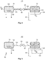
- Figure 4 shows a functional diagram of the high-current contact means 30 during a fifth method step 325
- Figure 5 shows a functional diagram of the high-current contact means 30 during a seventh method step 335.
- a first method step 305 the motor vehicle 10 is disconnected from the charging station 50 and the further high-current contact means 40 is removed from the high-current contact means 30.
- the valve 80 is in the closed position and in the first operating state. It is of particular advantage in this case if the valve 80 is kept de-energized in the closed position.
- the coolant container 70 is filled with liquid coolant 155.
- the coolant container 70 may be filled with, for example, 2 grams of coolant 155.
- the absorber material 190 is present in a dried state in the absorber container 75.
- the absorber material 190 preferably has an ambient temperature of the high-current contact means 30.
- 10 grams of absorber material 190 are provided in a dried state in the absorber container 75.
- the heating means 90 is deactivated and is de-energized, for example, by the control means 225.
- a charging operation is started.
- the charging operation is monitored and performed, for example, by the control device 25.
- the control means 225 in this case may connect the first electric lead 35 to the second electric lead 55.
- the control means 225 preferably determines an electric current I, transmitted via the contact element 60, for charging the traction battery 15. During charging, the contact element 60 heats up due to a first ohmic contact resistance between the contact surface 116 and the further contact element 210, a second ohmic contact resistance between the electric conductor 130 and the fastening portion 120, and an internal ohmic resistance of the contact element 60.
- the first temperature sensor 245 determines, for example, an outside temperature T A of the motor vehicle 10. Via the first signal line 240, the first temperature sensor 245 provides a first temperature signal, corresponding to the outside temperature T A , to the interface 235, which transfers the first temperature signal to the control means 225.
- the control means 225 can calculate a contact-element temperature T K of the contact element 60 on the basis of the predefined parameter, the determined outside temperature T A and the determined electric current I flowing through the contact element 60.
- the control means 225 compares the determined contact-element temperature T K , as an operating parameter of the contact element 60, with the predefined first threshold value S1.
- the first threshold value S1 may be, for example, 50 °C to 70 °C.
- the control means 225 continues with a fourth method step 320 if the operating parameter, in the exemplary embodiment the contact-element temperature T K , is less than the predefined first threshold value S1.
- the control means 225 continues with a fifth method step 325 if the contact-element temperature T K , as an operating parameter, is greater than the predefined first threshold value S1.
- the control means 225 continues to hold the valve 80 in the closed position, for example, by means of a closing signal.
- the second method step 310 is repeated.
- the control means 225 controls the valve 80 by means of an opening signal, which is transmitted to the valve 80 via the interface 235 and the control line 205, for example, in such a way that the valve 80 is moved from the closed position to the open position for the first time interval. In the open position, the valve 80 fluidically connects the coolant container 70 to the absorber container 75.
- the liquid coolant 155 changes from the liquid phase to a gaseous phase.
- the liquid coolant 155 absorbs a first heat Qs from the contact element 60 and thereby cools the contact element 60 ( Figures 4 and 5 show a first heat flow Qs of the first heat Qs from the contact element 60 to the coolant 155).
- Cooling of the contact element 60 ensures that the heating of the contact element 60 ensures a contact-element temperature T K of below, for example, 90 °C, although the high electric current I of between 40 amperes and 700 amperes, in particular between 200 amperes and 500 amperes, is transmitted via the contact element 60.
- the stripped portion 135 of the first electric lead 35 is also cooled.
- the cooling of the contact element 60 thus ensures that the traction battery 15 can be charged particularly quickly by means of the charging station 50 and that a charging operation for charging the traction battery 15 is particularly short.
- the cross-sectional area of the electric conductor 130 can be kept particularly small.
- the cross-sectional area can be reduced from the size mentioned above (50 mm 2 to 95 mm 2 ) to 45 mm 2 to 75 mm 2 .
- the cross-sectional area of the electric conductor 130 can be optimized in dependence on a duration of the current transmission via the contact element.
- the gaseous coolant 155 flows from the coolant container 70 into the fluid line 85 and via the valve 80 towards the absorber container 75.
- the absorber material 190 absorbs the gaseous coolant 155.
- the absorber material 190 heats up.
- the heat Q A produced in the absorption of the gaseous coolant 155 is absorbed by the absorber container 75 and emitted into the environment 110 of the high-current contact means 30 ( Figure 4 shows a second heat flow Q ⁇ A of the second heat Q A ).
- the emitted second heat Q A may in particular be emitted into an interior of the motor vehicle 10.
- the thermal insulation of the absorber container 75 from the housing 95 by the insulating layer 216 prevents the housing 95 from being damaged by the second heat Q A . Moreover, the absorber container 75 is prevented from heating the coolant container 70 and the coolant 155 contained therein.
- the predefined first time interval for example 30 to 180 minutes.
- the traction battery 15 is charged to such an extent that the current I transmitted via the contact element 60 for charging the traction battery 15 is reduced, thereby reducing the heating of the contact element 60.
- the charging operation of the traction battery 15 is completed to such an extent that a driver of the motor vehicle 10 may prematurely terminate the charging operation.
- the charging operation may be progressed to such an extent that the traction battery 15 is substantially fully charged.
- the cooling device 65 cools the contact element 60. The cooling process for cooling the contact element 60 ends when the coolant 155 has been completely changed from the liquid phase to the gas phase.
- the first time interval is such that there is sufficient time for the contact element 60 and the electric conductor 130 to cool down, following charging, substantially to the ambient temperature of the high-current contact means 30.
- the control means 225 activates the heating means 90 via the interface 235 (see Figure 5 ).
- the electric heating coil 195 is supplied with electrical energy from the traction battery 15.
- the heating coil 195 heats the absorber material 190 preferably to a temperature of between 150 °C and 300 °C. This causes the coolant 155 absorbed in the absorber material 190 to be vaporized and the absorber material 190 to be dried.
- the insulating layer 216 protects the housing 95 from thermal damage.
- the vaporised hot coolant 155 flows via the fluid line 85 and the open valve 80 into the coolant container 70. Due to the fact that it is thermally coupled to the contact element 60 and via the contact element 60 to the electric conductor 130, the coolant container 70 acts as a heat sink with respect to the coolant container 70. The gaseous coolant 155 condenses in the coolant container 70 and, following condensation, is present there again as liquid coolant 155. The heat dissipation Q ⁇ K from the coolant 155 that is necessary for condensation is dissipated via the contact element 60 and the electric conductor 130 and emitted to the environment 110.
- the electric conductor 130 has a particularly high heat capacity, owing to its large cross-section.
- the control means 225 deactivates the heating means 90 and controls the valve 80 by means of a closing signal in such a way that, in the eighth method step 340, the valve 80 is moved from the open position to the closed position.
- the method is continued with the second method step 310.
- the seventh and the eighth method step 335, 340 may be repeated at regular regeneration time intervals following the opening of the valve 80, in order to regenerate the absorber material 195 if there is a slight leakage of the valve 80.
- the regeneration time interval may be, for example, 24 h to 1 week. This ensures an optimal cooling capacity of the cooling means 65 if necessary.
- Figure 6 shows a flow diagram of a method according to a second embodiment, for operating the high-current contact means 30 shown in Figures 1 and 2 according to a second embodiment.
- a ninth method step 345 and a tenth method step 350 following the ninth method step 345 are performed between the sixth method step 330 and the seventh method step 335.
- the ninth method step 345 follows the sixth method step 330 and is substantially identical to the second method step 310.
- the operating parameter is determined again, such that the operating parameter is updated relative to the second method step 310.
- the outside temperature T A and the electric current I transmitted via the contact element 60 are determined again, and the contact-element temperature T K is determined again on the basis of the outside temperature T A , the transmitted electric current I and the parameter, for example as an operating parameter.
- the updated operating parameter for example the updated contact-element temperature T K determined in the ninth method step 345, is compared with a predefined second threshold value S2 stored in the data storage means 230.
- the process continues with the seventh method step 335. If the determined contact-element temperature T K exceeds the second threshold value S2, the process continues with the sixth method step 330, and the first time interval is waited again.
- the first time interval is shortened compared to Figure 3 .
- the first time interval may be 15 minutes to 30 minutes.
- the second threshold value S2 is preferably lower than the first threshold value S1.
- the second threshold value S2 may be, for example, 30 °C to 50 °C.
- the current I transmitted via the contact element 60 may also be used as an operating parameter instead of the contact-element temperature T K .
- the first threshold value S1 has a value of 50 amperes to 200 amperes.
- the second threshold value S2 is selected to be smaller than the first threshold value S1 and may be, for example, 30 amperes to 100 amperes.
- the design of the high-current contact means 30 described above has the advantage that there is no need for further cooling devices 65.
- the cooling device 65 is integrated into the high-current contact means 30, such that, in particular, there is no need for large heat sinks for passive cooling, fans for active cooling or similar.
- the cross-section of the electric conductor 130 can be kept particularly small. This results in a large saving in weight for connection of the electric conductor 130 to the control device 25 and the traction battery 15.
- the first electric lead 35 can be laid in particularly tight radii, such that the installation space required for realizing the high-current vehicle electrical system is reduced.
- the cooling device 65 may be provided for each of the contact elements 60.
- an absorber container 75 may be fluidically connected, for example via a plurality of fluid lines 85, to a plurality of coolant containers 70, each of which is arranged on a contact element 60. This design has the advantage that each of the contact elements 60 of the high-current contact means 30 is cooled.
- the integrated cooling device 65 also allows the installation space requirement and the mass of the high-current contact means 30 to be reduced. Moreover, a mass of the high-current contact means 30 can be reduced.
Landscapes
- Engineering & Computer Science (AREA)
- Mechanical Engineering (AREA)
- Power Engineering (AREA)
- Transportation (AREA)
- Materials Engineering (AREA)
- Chemical & Material Sciences (AREA)
- Physics & Mathematics (AREA)
- Thermal Sciences (AREA)
- General Engineering & Computer Science (AREA)
- Manufacturing & Machinery (AREA)
- Electric Propulsion And Braking For Vehicles (AREA)
- Secondary Cells (AREA)
- Arrangement Or Mounting Of Propulsion Units For Vehicles (AREA)
Abstract
Description
- The invention relates to a high-current contact means according to Claim 1, and to a method for operating the high-current contact means according to Claim 8.
- There are known charging sockets for electric motor vehicles. The charging sockets each have a contact element that is connected to a thick electric cable in order to transmit the electric current between the charging socket and a control device, or traction battery. The transmitted power causes the contact element to heat up significantly. In order to avoid significant overheating of the contact element, a maximum electric power can only be transmitted via the contact element for a short period of time before the electric power to be transmitted has to be reduced in order to avoid overheating of the contact element.
- It is an object of the invention to provide an improved high-current contact means and a method for operating such a high-current contact means.
- This object is achieved by means of a high-current contact means according to Claim 1, and by means of a method for operating the high-current contact means according to Claim 8. Advantageous embodiments are specified in the dependent claims.
- It was recognised that an improved high-current contact means for a motor vehicle can be provided by the high-current contact means comprising a contact element and a cooling device. The cooling device has a coolant container, an absorber container, a valve and a fluid line. The coolant container is thermally connected to the contact element. The absorber container is arranged at a distance from the coolant container and the contact element. The coolant container is at least partially filled with a liquid coolant, and the absorber container is at least partially filled with an absorber material. The valve is arranged in the fluid line. The fluid line runs between the coolant container and the absorber container. The valve is adjustable between an open position and a closed position. In the open position the coolant container is fluidically connected to the absorber container, and in the closed position the coolant container is fluidically separated from the absorber container. In the open position the coolant is designed to change to a gaseous phase in the coolant container and to cool the contact element. The fluid line is designed to convey the gaseous coolant from the coolant container to the absorber container. The absorber material is designed to absorb the gaseous coolant.
- This design has the advantage that the heat required for the phase conversion is extracted from the contact element and thus the contact element is cooled particularly well. Due to the cooling of the contact element, overheating of the contact element can be avoided. In particular, in the case of high-current transmission in a range of from 150 amperes to 700 amperes, in particular in a range of from 200 amperes to 500 amperes, an internal resistance of the contact element and/or a contact resistance between the contact element and a further contact element to which the contact element can be contacted, and/or a further contact resistance between the contact element and an electric conductor, is already sufficient to cause significant heating of the contact element. Due to the cooling of the contact element by means of the cooling device, overheating of the contact element is avoided. In particular, this allows a particularly high electric power, in particular in a range of from 200 kW to 500 kW, to be transmitted via the contact element over a longer period of time without the electric power in this case having to be reduced with increasing duration.
- Furthermore, the cooling device is integrated into the high-current contact means, such that further cooling devices for cooling the contact element are not required. The high-current contact means is thus of a particularly simple and cost-effective design.
- In another embodiment, there is a heating means arranged in the absorber container, the heating means being designed to heat the absorber material to a predefined temperature in order to remove the absorbed coolant, in particular to vaporize it. This design has the advantage that it is possible to regenerate the absorber material and the coolant, and following heating of the coolant the absorber material is again able to receive gaseous coolant. Consequently, following regeneration of the absorber material, the contact element can be cooled multiple times by the cooling means.
- It is particularly advantageous in this case if the heating means has an electric heating coil, the heating coil being at least partially embedded in the absorber material. It can thus be ensured that there is a good transfer of heat between the heating coil and the absorber material, such that the amount of electrical energy required to energize the heating coil for the purpose of regenerating the absorber material is particularly small. Since the electrical energy for heating the electric heating coil in an electric or a hybrid vehicle is taken from the traction battery, an economical heating coil is of particular advantage.
- In another embodiment, the fluid line is realized, for example, as a U-shaped line. The fluid line has a first sub-portion that leads into the coolant container, a second sub-portion that leads into the absorber container, and an intermediate portion that fluidically connects the first sub-portion to the second sub-portion. The intermediate portion of the fluid line is arranged on the top side of the coolant container and/or the absorber container. This design ensures that, when the high-current contact means is fitted in the motor vehicle, an unintentional transfer of the liquid coolant from the coolant container into the absorber container is prevented by the intermediate portion arranged on the top side. As a result, the functionality of the cooling device is ensured, and the transfer of liquid coolant into the absorber container is prevented.
- In another embodiment, the contact element has a contact portion for electrically contacting a further high-current contact means, and has a fastening portion that is electrically and mechanically connected to the contact portion. At the fastening portion, an electric conductor of an electric lead is connectable to the fastening portion on a first side. On a second side of the fastening portion that faces away from the first side, the coolant container is thermally and preferably mechanically connected to the fastening portion. This design has the advantage that the contact element can be cooled particularly well. Both the contact element and the electric lead have a high thermal capacity and thermal conductivity in order to dissipate heat from the gaseous coolant for condensation of the coolant. It is thereby ensured that, in the regeneration of the cooling device, the contact element and additionally the electric lead serve as a heat sink for cooling and condensation of the gaseous coolant in the coolant container.
- In another embodiment, the valve is designed to be electrically controllable and can be electrically connected to a control device. This design has the advantage that the cooling device can be activated and deactivated by switching the valve in dependence on an operating parameter of the contact element.
- In another embodiment, the high-current contact means has a housing that at least partially delimits a housing interior on the inside. The coolant container is arranged in the housing interior. The absorber container is arranged on an outer side of the housing. This design ensures that, upon the heating means being activated, the coolant container in which the coolant condenses is not unwantedly heated by the heating means.
- In another embodiment, the absorber material has a crystal structure and/or comprises zeolite and/or activated carbon and/or silicate, in particular silicate gel and/or sodium dichromate and/or lithium bromide and/or lithium hydroxide. Additionally or alternatively, the coolant comprises at least water and/or alcohol and/or glycol.
- In a method for operating the contact means described above, the valve is moved from the closed position to the open position. The liquid coolant present in the coolant container changes from the liquid phase to the gaseous phase, and the coolant cools the contact element. The gaseous coolant flows via the fluid line into the absorber container. The absorber material absorbs the gaseous coolant. This design has the advantage that, due to the phase conversion between the liquid phase, in which the coolant is present in the coolant container, and the gaseous phase, a particularly large amount of heat can be absorbed from the contact element by the coolant, and thus the contact element can be cooled particularly effectively.
- In another embodiment, an operating parameter of the contact element is determined. If a predefined threshold value is exceeded by the determined operating parameter, the valve is moved from the closed position to the open position. The operating parameter may be, for example, a contact-element temperature. The operating parameter may be determined, for example, on the basis of an ambient temperature of the high-current contact means and/or of an electric current transmitted via the contact element. The operating parameter may also be the electric current transmitted via the contact element. This design has the advantage of avoiding unnecessary activation of the cooling device, for example when a low electric current (for example less than 50 amperes) is transmitted via the contact element or the contact element only heats up slightly due to a low outside temperature. This means that the cooling device is still available if, for example, the charging station is changed in order to transmit a high current via the contact element. Furthermore, the service life of the cooling means is extended and an unnecessary load on the traction battery is avoided.
- In another embodiment, following switchover of the valve to the open position, the valve is kept in the open position for a predefined first time interval of, for example, 30 minutes to three hours. It is thereby ensured that the coolant present in the coolant container can be completely changed to the gas phase.
- In another embodiment, the contact element is cooled down after transmission of current via the contact element has ended. The cooling may be effected passively to the environment if the cooling device no longer has a cooling effect. The heating means is activated after the contact element has cooled below a predefined second threshold value, and the absorber material is heated to a predefined temperature, such that the coolant stored in the absorber material is changed to its gaseous phase. The gaseous coolant flows from the absorber container to the coolant container via the fluid line and condenses in the coolant container. This design has the advantage that safe condensing of the coolant in the coolant container is ensured.
- In another embodiment, the heating means heats the absorber material to a temperature of 150 °C to 300 °C, such that the absorbed coolant is vaporized. The regeneration of the absorber material is thus effected particularly rapidly.
- In another embodiment, the valve is switched over from the open position to the closed position following deactivation of the heating means. This ensures that the cooling device is deactivated and can be activated if required.
- In another embodiment, the valve is moved in a periodically iterative manner from the closed position to the open position in a regular regeneration time interval, and the heating means is activated substantially simultaneously, such that the absorber material is heated to the predefined temperature and the coolant stored in the absorber material is changed to its gaseous phase. The gaseous coolant flows from the absorber container to the coolant container via the fluid line and condenses in the coolant container, the valve being switched over from the open position to the closed position following deactivation of the heating means. The cooling capacity of the cooling device can thus be ensured when necessary, even if there is a slight leakage of the valve.
- The invention is explained in greater detail in the following on the basis of figures. There are shown therein:
-
Figure 1 a schematic representation of a motor vehicle; -
Figure 2 a sectional view, along a sectional plane A-A shown inFigure 1 , through a high-current contact means of the motor vehicle shown inFigure 1 ; -
Figure 3 a flow diagram of a method for operating the high-current contact means shown inFigures 1 and2 , according to a first embodiment; -
Figure 4 a functional diagram of the high-current contact means during a fifth method step; -
Figure 5 a functional diagram of the high-current contact means during a seventh method step; -
Figure 6 a flow diagram of a method according to a second embodiment for operating the high-current contact means shown inFigures 1 and2 . - In the following figures reference is made to a coordinate system. The coordinate system in this case has an x-axis (longitudinal direction), a y-axis (transverse direction) and a z-axis (vertical direction).
-
Figure 1 shows a schematic representation of amotor vehicle 10. - In the embodiment, the
motor vehicle 10 is exemplarily realized as a hybrid vehicle or as an electric vehicle. The motor vehicle may be a passenger car or a truck, in particular a light-duty truck. Themotor vehicle 10 has atraction battery 15, adrive motor 20, acontrol device 25 and a high-current contact means 30. Thetraction battery 15 is designed to store electrical energy and has a capacity of, for example, 30 kWh to 100 kWh. Thedrive motor 20 is designed to drive themotor vehicle 10 when electrical energy is provided from thetraction battery 15. - The high-current contact means 30 is designed, for example, as a charging plug or charging socket and is mounted with a predefined orientation in the
motor vehicle 10. The high-current contact means 30 is electrically connected to thecontrol device 25 by means of a firstelectric lead 35. Thecontrol device 25 is electrically connected to thetraction battery 15 by means of a secondelectric lead 55. Thecontrol device 25 may be realized, for example, as a charging device for charging thetraction battery 15. - When the
motor vehicle 10 is in a charging state, mounted on the high-current contact means 30 there is a further high-current contact means 40 that is electrically connected to a chargingstation 50 by means of a chargingcable 45. The chargingstation 50 is realized, for example, as a rapid charging station. The chargingstation 50 is designed to provide electric power in the range of from at least 50 kW to 500 kW, preferably from at least 150 kW to 500 kW, for charging thetraction battery 15 at a voltage of preferably 700 volts to 1200 volts. As a result, a charging current may be approximately 40 amperes to 700 amperes. The electric power is transmitted via the chargingcable 45 from the chargingstation 50 to the further high-current contact means 40. The electric power is transmitted to the high-current contact means 30 when the further high-current contact means 40 has been mounted on the high-current contact means 30. The electric power is charged from the high-current contact means 30 via the firstelectric lead 35 to thecontrol device 25, and from thecontrol device 25 via the secondelectric lead 55 to thetraction battery 15. This allows particularly rapid charging of thetraction battery 15. -
Figure 2 shows a sectional view, along a sectional plane A-A shown inFigure 1 , through the high-current contact means 30 shown inFigure 1 . - The high-current contact means 30 has a
contact element 60, acooling device 65 for cooling thecontact element 60 and ahousing 95 for mechanically fastening thecontact element 60. Preferably, the high-current contact means 30 has a plurality ofcontact elements 60, only onecontact element 60 being represented, as an example, inFigure 2 . The functionality of the high-current contact means 30 shown inFigure 2 is explained with reference to thecontact element 60. - The
housing 95 may be mechanically connected to abody 96 of themotor vehicle 10. Thehousing 95 has ahousing interior 100 and afirst leadthrough 105. Thehousing interior 100 of the high-current contact means 30 is preferably sealed off from anenvironment 110. Thecontact element 60 extends, with acontact portion 115 that in the embodiment is of a pin type, through thefirst leadthrough 105 of thehousing 95 and protrudes, with a first sub-portion of thecontact portion 115, from thehousing 95. Arranged on the circumference of thecontact portion 115, outside thehousing 95, there is acontact surface 116 for electrical contacting. - The
contact element 60 has a plate-shapedfastening portion 120. Thefastening portion 120 is both electrically and mechanically and thermally connected to thecontact portion 115, and adjoins thecontact portion 115 on a side that faces away from thecontact surface 116. Preferably, thecontact portion 115 and thefastening portion 120 are made, in one piece and of the same material, from an electrically conductive and thermally conductive material such as, for example, copper and/or aluminium and/or steel. - The further high-current contact means 40 (represented by a dashed line in
Figure 2 ) has afurther contact element 210, thefurther contact element 210 electrically and mechanically contacting the contact surface of thecontact portion 115, for example, when the further high-current contact means 40 has been mounted on the high-current contact means 30. Thefurther contact element 210 is electrically connected to the chargingstation 50 via the chargingcable 45. - The
fastening portion 120 is arranged in thehousing interior 100. Moreover, the firstelectric lead 35 is routed into thehousing interior 100 via asecond leadthrough 125 of thehousing 95. The firstelectric lead 35 has anelectric conductor 130, theelectric conductor 130 preferably having a cross-sectional area of from 50 mm2 to 95 mm2. Theelectric conductor 130 may be fine-stranded or ultrafine-stranded. In a strippedportion 135 of the firstelectric lead 35, an electrically insulatingsheath 140 of the firstelectric lead 35 is removed from theelectric conductor 130. The strippedportion 135 is attached, for example welded, to thefastening portion 120, on afirst side 145 of thefastening portion 120. - In the embodiment, for example, one
cooling device 65 is provided for eachcontact element 60. Thecooling device 65 has acoolant container 70, anabsorber container 75, an electricallyswitchable valve 80, afluid line 85 and a heating means 90. - The
coolant container 70 is thermally coupled to thecontact element 60. In the embodiment, thecoolant container 70 is thermally and mechanically connected, for example, to thefastening portion 120 on asecond side 150 that is opposite thefirst side 145 in the y-direction. For example, thefastening portion 120 and thecoolant container 70 may be connected in a materially bonded manner, for example soldered or welded. Thesecond side 150 may be flat, for example. - The
coolant container 70 could also be spaced apart from thecontact element 60 and, for example, be thermally connected to thefastening portion 120 via a thermallyconductive material 151, for example a thermally conductive compound. In the embodiment shown inFigure 2 , thecoolant container 70 is for example additionally embedded in the thermallyconductive material 151, at least in certain areas, such that thecoolant container 70 is thermally connected to thefastening portion 120, and thus to thecontact element 60, in a particularly efficient manner. - In the embodiment, the
coolant container 70 has a capacity of at least 1.5 cm3, preferably 2 mm3, to 8 cm3. When the high-current contact means 30 is in a first operating state there is acoolant 155 present in thecoolant container 70. Thecoolant 155 may comprise, for example, water. Also, thecoolant 155 may comprise another liquid, for example alcohol and/or glycol in addition to or as an alternative to water. Thecoolant 155 is preferably frost-proof to at least 25 °C, in particular -40 °C. - On a side that faces towards the
second leadthrough 125, thefluid line 85 leads at afirst end 160 into thecoolant container 70. In the embodiment, as an example, thefluid line 85 is of a U-shaped design. Thefluid line 85 has anintermediate portion 165 and, for example, afirst sub-portion 170 and asecond sub-portion 180. Thefirst sub-portion 170 extends substantially in the z-direction, between thefirst end 160 and theintermediate portion 165, along a first straight line. As shown inFigure 2 , thefirst sub-portion 170 in this case may be oriented obliquely relative to a direction of extent of theelectric conductor 130 and/or of the z-axis. Thefirst sub-portion 170 extends through athird leadthrough 175 of thehousing 95. Theintermediate portion 165 is arranged, offset in the z-direction from thecoolant container 70, outside of thehousing 95. - The
second sub-portion 180 adjoins theintermediate portion 165 on a side that faces away from the first sub-portion 170 (in the y-direction). As an example, thesecond sub-portion 180 runs parallel to the z-axis, as does theelectric conductor 130. Thesecond sub-portion 180 leads, at asecond end 185 of thefluid line 85, into theabsorber container 75. - The
absorber container 75 is at least partially, preferably completely, filled with anabsorber material 190. Theabsorber material 190 may have, for example, a crystal structure, preferably a coolant-absorbing crystal structure and/or comprise zeolite and/or activated carbon and/or silicate, in particular silicate gel and/or sodium dichromate and/or lithium bromide and/or lithium hydroxide. Additionally or alternatively, thecoolant 155 comprises at least water and/or alcohol and/or glycol. It is particularly advantageous if theabsorber container 75, thecoolant container 70 and thefluid line 85 are under vacuum, such that a gas pressure, for example in thefluid line 85 and/or theabsorber container 75 and/or thecoolant container 70, is between 0.00001 MPa and 0.01 MPa in the first operating state. - The heating means 90 has, for example, at least one
electric heating coil 195 and asupply line 200. Thesupply line 200 electrically connects theheating coil 195 to thecontrol device 25. Preferably, theheating coil 195 is completely embedded in theabsorber material 190. Embedding in this case is understood to mean that theheating coil 195 is completely enclosed by theabsorber material 190. - The
valve 80 is electrically connected to thecontrol device 25 by means of acontrol line 205. In the embodiment, thevalve 80 is arranged, for example, in theintermediate portion 165. A different arrangement of thevalve 80 is also possible, for example in the first orsecond sub-portion - The
valve 80 has a closed position and an open position, thevalve 80 being movable between the open position and the closed position. In the closed position, thevalve 80 fluidically separates theabsorber container 75 from thecoolant container 70. In the open position, thefluid line 85 fluidically connects thecoolant container 70 to theabsorber container 75. - In the embodiment, the
intermediate portion 165 is for example arranged (in the z-direction) above thefirst sub-portion 170 and/or thesecond sub-portion 180. When the high-current contact means 30 has been fitted in themotor vehicle 10, thecoolant container 70 is arranged, for example, below theabsorber container 75 in the z-direction. Theabsorber container 75 and thecoolant container 70 may also be arranged at the same level. Alternatively, it would also be possible for thecoolant container 70 to be arranged above theabsorber container 75. Moreover, when the high-current contact means 30 has been fitted to themotor vehicle 10, theintermediate portion 165 is arranged above thecoolant container 70 and/or theabsorber container 75. For example, thesecond leadthrough 125 and thethird leadthrough 175 are arranged in a common xy-plane and above thecontact element 60. The U-shaped design of thefluid line 85 has the advantage that, when thevalve 80 is in the open position, an unwanted overflow of theliquid coolant 155 from thecoolant container 70 into theabsorber container 75 is avoided. - The
absorber container 75 is attached to ahousing web 215 of anouter housing side 220 of thehousing 95 on a side of thehousing 95 that faces away from thecontact surface 116. A thermal insulatinglayer 216, which thermally insulates theabsorber container 75 from thehousing 95, in particular from thecoolant container 70, may be provided in this case between theabsorber container 75 and thehousing 95. - The
control device 25 comprises a control means 225, a data storage means 230 having a data connection to the control means 225, and aninterface 235 connected to the control means 225. - A value for a first time interval, a value for a second time interval and a first threshold value S1 are stored in the data storage means 230. In addition, there may be a parameter stored in the data storage means 230. The parameter may be, for example, a tabular assignment, a mathematical algorithm, a computer program or a characteristic diagram.
- The
interface 235 is connected to thecontrol line 205, thesupply line 200 and preferably to theelectric conductor 130 of the firstelectric lead 35 and to the secondelectric lead 55. In addition, theinterface 235 may be connected to atemperature sensor 245 of themotor vehicle 10 via afirst signal line 240. Thetemperature sensor 245 may be provided, for example as an outside-temperature sensor in themotor vehicle 10. Thefirst signal line 240, thesupply line 200 and/or thecontrol line 205 may be part of a bus system, in particular a CAN bus. -
Figure 3 shows a flow diagram of a method for operating the high-current contact means 30 shown inFigures 1 and2 , according to a first embodiment.Figure 4 shows a functional diagram of the high-current contact means 30 during afifth method step 325, andFigure 5 shows a functional diagram of the high-current contact means 30 during aseventh method step 335. - In a
first method step 305, themotor vehicle 10 is disconnected from the chargingstation 50 and the further high-current contact means 40 is removed from the high-current contact means 30. In thefirst method step 305, thevalve 80 is in the closed position and in the first operating state. It is of particular advantage in this case if thevalve 80 is kept de-energized in the closed position. - Further, the
coolant container 70 is filled withliquid coolant 155. For example, thecoolant container 70 may be filled with, for example, 2 grams ofcoolant 155. Further, in thefirst method step 305, theabsorber material 190 is present in a dried state in theabsorber container 75. Theabsorber material 190 preferably has an ambient temperature of the high-current contact means 30. Preferably, for 2 grams ofcoolant absorber material 190 are provided in a dried state in theabsorber container 75. Further, in thefirst method step 305, the heating means 90 is deactivated and is de-energized, for example, by the control means 225. - In a
second method step 310, the further high-current contact means 40 is plugged onto the high-current contact means 30 and a charging operation is started. The charging operation is monitored and performed, for example, by thecontrol device 25. The control means 225 in this case may connect the firstelectric lead 35 to the secondelectric lead 55. - The control means 225 preferably determines an electric current I, transmitted via the
contact element 60, for charging thetraction battery 15. During charging, thecontact element 60 heats up due to a first ohmic contact resistance between thecontact surface 116 and thefurther contact element 210, a second ohmic contact resistance between theelectric conductor 130 and thefastening portion 120, and an internal ohmic resistance of thecontact element 60. - During the
second method step 310, thefirst temperature sensor 245 determines, for example, an outside temperature TA of themotor vehicle 10. Via thefirst signal line 240, thefirst temperature sensor 245 provides a first temperature signal, corresponding to the outside temperature TA, to theinterface 235, which transfers the first temperature signal to the control means 225. - The control means 225 can calculate a contact-element temperature TK of the
contact element 60 on the basis of the predefined parameter, the determined outside temperature TA and the determined electric current I flowing through thecontact element 60. - In a
third method step 315 following thesecond method step 310, the control means 225 compares the determined contact-element temperature TK, as an operating parameter of thecontact element 60, with the predefined first threshold value S1. The first threshold value S1 may be, for example, 50 °C to 70 °C. The control means 225 continues with afourth method step 320 if the operating parameter, in the exemplary embodiment the contact-element temperature TK, is less than the predefined first threshold value S1. The control means 225 continues with afifth method step 325 if the contact-element temperature TK, as an operating parameter, is greater than the predefined first threshold value S1. - In the
fourth method step 320, the control means 225 continues to hold thevalve 80 in the closed position, for example, by means of a closing signal. After thefourth method step 320, thesecond method step 310 is repeated. - In the fifth method step 325 (see
Figure 4 ), the control means 225 controls thevalve 80 by means of an opening signal, which is transmitted to thevalve 80 via theinterface 235 and thecontrol line 205, for example, in such a way that thevalve 80 is moved from the closed position to the open position for the first time interval. In the open position, thevalve 80 fluidically connects thecoolant container 70 to theabsorber container 75. - As a result of the opening of the
valve 80, theliquid coolant 155 changes from the liquid phase to a gaseous phase. To effect the phase change, theliquid coolant 155 absorbs a first heat Qs from thecontact element 60 and thereby cools the contact element 60 (Figures 4 and 5 show a first heat flow Qs of the first heat Qs from thecontact element 60 to the coolant 155). Cooling of thecontact element 60 ensures that the heating of thecontact element 60 ensures a contact-element temperature TK of below, for example, 90 °C, although the high electric current I of between 40 amperes and 700 amperes, in particular between 200 amperes and 500 amperes, is transmitted via thecontact element 60. Moreover, as a result of the cooling of thecontact element 60, the strippedportion 135 of the firstelectric lead 35 is also cooled. - Due to the cooling, there is no need to reduce the electric power for charging the
traction battery 15. - The cooling of the
contact element 60 thus ensures that thetraction battery 15 can be charged particularly quickly by means of the chargingstation 50 and that a charging operation for charging thetraction battery 15 is particularly short. Moreover, the cross-sectional area of theelectric conductor 130 can be kept particularly small. Thus, for example, the cross-sectional area can be reduced from the size mentioned above (50 mm2 to 95 mm2) to 45 mm2 to 75 mm2. Furthermore, the cross-sectional area of theelectric conductor 130 can be optimized in dependence on a duration of the current transmission via the contact element. - The
gaseous coolant 155 flows from thecoolant container 70 into thefluid line 85 and via thevalve 80 towards theabsorber container 75. In theabsorber container 75, theabsorber material 190 absorbs thegaseous coolant 155. In the process, theabsorber material 190 heats up. The heat QA produced in the absorption of thegaseous coolant 155 is absorbed by theabsorber container 75 and emitted into theenvironment 110 of the high-current contact means 30 (Figure 4 shows a second heat flow Q̇A of the second heat QA). The emitted second heat QA may in particular be emitted into an interior of themotor vehicle 10. The thermal insulation of theabsorber container 75 from thehousing 95 by the insulatinglayer 216 prevents thehousing 95 from being damaged by the second heat QA. Moreover, theabsorber container 75 is prevented from heating thecoolant container 70 and thecoolant 155 contained therein. - In a
sixth method step 330, the predefined first time interval, for example 30 to 180 minutes, is waited. Within the first time interval, thetraction battery 15 is charged to such an extent that the current I transmitted via thecontact element 60 for charging thetraction battery 15 is reduced, thereby reducing the heating of thecontact element 60. Preferably, within 30 minutes after opening of thevalve 80, the charging operation of thetraction battery 15 is completed to such an extent that a driver of themotor vehicle 10 may prematurely terminate the charging operation. Alternatively, the charging operation may be progressed to such an extent that thetraction battery 15 is substantially fully charged. Within the first time interval and during charging, thecooling device 65 cools thecontact element 60. The cooling process for cooling thecontact element 60 ends when thecoolant 155 has been completely changed from the liquid phase to the gas phase. - In addition, the first time interval is such that there is sufficient time for the
contact element 60 and theelectric conductor 130 to cool down, following charging, substantially to the ambient temperature of the high-current contact means 30. - In a
seventh method step 335 following the sixth method step 330 (i.e. following the waiting of the first time interval), the control means 225 activates the heating means 90 via the interface 235 (seeFigure 5 ). Upon activation of the heating means 90, theelectric heating coil 195 is supplied with electrical energy from thetraction battery 15. Theheating coil 195 heats theabsorber material 190 preferably to a temperature of between 150 °C and 300 °C. This causes thecoolant 155 absorbed in theabsorber material 190 to be vaporized and theabsorber material 190 to be dried. The insulatinglayer 216 protects thehousing 95 from thermal damage. - The vaporised
hot coolant 155 flows via thefluid line 85 and theopen valve 80 into thecoolant container 70. Due to the fact that it is thermally coupled to thecontact element 60 and via thecontact element 60 to theelectric conductor 130, thecoolant container 70 acts as a heat sink with respect to thecoolant container 70. Thegaseous coolant 155 condenses in thecoolant container 70 and, following condensation, is present there again asliquid coolant 155. The heat dissipation Q̇K from thecoolant 155 that is necessary for condensation is dissipated via thecontact element 60 and theelectric conductor 130 and emitted to theenvironment 110. Theelectric conductor 130 has a particularly high heat capacity, owing to its large cross-section. - Following the elapse of a second time interval, in which the heating means 90 is activated by the control means 225, for example 15 minutes to 30 minutes, the control means 225 deactivates the heating means 90 and controls the
valve 80 by means of a closing signal in such a way that, in theeighth method step 340, thevalve 80 is moved from the open position to the closed position. - After the
eighth method step 340, the method is continued with thesecond method step 310. - The seventh and the
eighth method step valve 80, in order to regenerate theabsorber material 195 if there is a slight leakage of thevalve 80. The regeneration time interval may be, for example, 24 h to 1 week. This ensures an optimal cooling capacity of the cooling means 65 if necessary. -
Figure 6 shows a flow diagram of a method according to a second embodiment, for operating the high-current contact means 30 shown inFigures 1 and2 according to a second embodiment. - The method is substantially identical to the method explained in
Figure 3 . In the following, only the differences between the method described inFigure 6 and the method described inFigure 3 will be discussed. - In addition, a
ninth method step 345 and atenth method step 350 following theninth method step 345 are performed between thesixth method step 330 and theseventh method step 335. - The
ninth method step 345 follows thesixth method step 330 and is substantially identical to thesecond method step 310. In theninth method step 345, the operating parameter is determined again, such that the operating parameter is updated relative to thesecond method step 310. In this case, as in thesecond method step 310, the outside temperature TA and the electric current I transmitted via thecontact element 60 are determined again, and the contact-element temperature TK is determined again on the basis of the outside temperature TA, the transmitted electric current I and the parameter, for example as an operating parameter. - In a
tenth method step 350 following theninth method step 345, the updated operating parameter, for example the updated contact-element temperature TK determined in theninth method step 345, is compared with a predefined second threshold value S2 stored in the data storage means 230. - If the determined contact-element temperature TK is below the second threshold value S2, the process continues with the
seventh method step 335. If the determined contact-element temperature TK exceeds the second threshold value S2, the process continues with thesixth method step 330, and the first time interval is waited again. Advantageously, in the embodiment the first time interval is shortened compared toFigure 3 . Thus, the first time interval may be 15 minutes to 30 minutes. When the first time interval is waited again, the charging operation for charging thetraction battery 15 may be completed, and/or there is sufficient time for thecontact element 60 and theelectric conductor 130 to cool down to the ambient temperature. - The second threshold value S2 is preferably lower than the first threshold value S1. In the embodiment, the second threshold value S2 may be, for example, 30 °C to 50 °C.
- As an alternative to the determination of the operating parameter of the
contact element 60 described above, for example the current I transmitted via thecontact element 60 may also be used as an operating parameter instead of the contact-element temperature TK. For example, the first threshold value S1 has a value of 50 amperes to 200 amperes. The second threshold value S2 is selected to be smaller than the first threshold value S1 and may be, for example, 30 amperes to 100 amperes. - The design of the high-current contact means 30 described above has the advantage that there is no need for
further cooling devices 65. Thecooling device 65 is integrated into the high-current contact means 30, such that, in particular, there is no need for large heat sinks for passive cooling, fans for active cooling or similar. In addition, owing to the cooling of thecontact element 60 and of theelectric conductor 130 connected to thecontact element 60, the cross-section of theelectric conductor 130 can be kept particularly small. This results in a large saving in weight for connection of theelectric conductor 130 to thecontrol device 25 and thetraction battery 15. Moreover, due to the smaller cross-section, the firstelectric lead 35 can be laid in particularly tight radii, such that the installation space required for realizing the high-current vehicle electrical system is reduced. - If the high-current contact means 30 has a plurality of
contact elements 60, thecooling device 65 may be provided for each of thecontact elements 60. Alternatively, anabsorber container 75 may be fluidically connected, for example via a plurality offluid lines 85, to a plurality ofcoolant containers 70, each of which is arranged on acontact element 60. This design has the advantage that each of thecontact elements 60 of the high-current contact means 30 is cooled. - Furthermore, the
integrated cooling device 65 also allows the installation space requirement and the mass of the high-current contact means 30 to be reduced. Moreover, a mass of the high-current contact means 30 can be reduced. -
- 10
- motor vehicle
- 15
- traction battery
- 20
- drive motor
- 25
- control device
- 30
- high-current contact means
- 35
- first electric lead
- 40
- further high-current contact means
- 45
- charging cable
- 50
- charging station
- 55
- second electric lead
- 60
- contact element
- 65
- cooling device
- 70
- coolant container
- 75
- absorber container
- 80
- valve
- 85
- fluid line
- 90
- heating means
- 95
- housing
- 96
- body
- 100
- housing interior
- 105
- first leadthrough
- 110
- environment
- 115
- contact portion
- 116
- contact surface
- 120
- fastening portion
- 125
- second leadthrough
- 130
- electric conductor
- 135
- stripped portion
- 140
- sheath
- 145
- first side
- 150
- second side
- 151
- thermally conductive material
- 155
- coolant
- 160
- first end
- 165
- intermediate portion
- 170
- first sub-portion
- 175
- third leadthrough
- 180
- second sub-portion
- 185
- second end
- 190
- absorber material
- 195
- heating coil
- 200
- supply line
- 205
- control line
- 210
- further contact element
- 215
- housing web
- 216
- insulating layer
- 220
- housing outer side
- 225
- control means
- 230
- data storage means
- 235
- interface
- 240
- first signal line
- 245
- first temperature sensor
- 250
- second signal line
- 255
- second temperature sensor
- 305
- first method step
- 310
- second method step
- 315
- third method step
- 320
- fourth method step
- 325
- fifth method step
- 330
- sixth method step
- 335
- seventh method step
- 340
- eighth method step
- 345
- ninth method step
- 350
- tenth method step
- QS
- first heat
- QA
- second heat
- QK
- heat
- TK
- contact-element temperature
- TA
- outside temperature
- I
- transmitted electrical current/charging current
Claims (14)
- High-current contact means (30), in particular charging plug for a motor vehicle (10),- comprising a contact element (60) and a cooling device (65) that has a coolant container (70), an absorber container (75), a valve (80) and a fluid line (85),- the coolant container (70) being thermally connected to the contact element (60), and the absorber container (75) being arranged at a distance from the coolant container (70) and the contact element (60),- the coolant container (70) being at least partially filled with a liquid coolant (155), and the absorber container (75) being at least partially filled with an absorber material (190),- the valve (80) being arranged in the fluid line (85), and the fluid line (85) running between the coolant container (70) and the absorber container (75),- the valve (80) being adjustable between an open position and a closed position,- in the open position the coolant container (70) being fluidically connected to the absorber container (75), and in the closed position the coolant container (70) being fluidically separated from the absorber container (75),- in the open position the coolant (155) being designed to change to a gaseous phase in the coolant container (70) and to cool the contact element (60), and the fluid line (85) being designed to convey the gaseous coolant (155) from the coolant container (70) to the absorber container (75),- the absorber material (190) being designed to absorb the gaseous coolant (155).
- High-current contact means (30) according to Claim 1,- there being a heating means (90) arranged in the absorber container (75),- the heating means (90) being designed to heat the absorber material (190) to a predefined temperature in order to remove the absorbed coolant (155) from the absorber material (190).
- High-current contact means (30) according to Claim 2,- the heating means (90) having at least one electric heating coil (195),- the heating coil (195) being at least partially embedded in the absorber material (190).
- High-current contact means (30) according to any one of the preceding claims,- the fluid line (85) having a first sub-portion (170) that leads into the coolant container (70), a second sub-portion (175) that leads into the absorber container (75), and an intermediate portion (165) that fluidically connects the first sub-portion (170) to the second sub-portion (175),- the intermediate portion (165) of the fluid line (85) being arranged on the top side of the coolant container (70) and/or the absorber container (75).
- High-current contact means (30) according to any one of the preceding claims,- the contact element (60) having a contact portion (115) for electrically contacting a further high-current contact means (40), and having a fastening portion (120) that is electrically and mechanically connected to the contact portion (115),- at the fastening portion (120), an electric conductor (135) of a first electric lead (35) being connectable to the fastening portion (120) on a first side (145),- on a second side (150) of the fastening portion (120) that faces away from the first side (145), the coolant container (70) being thermally and preferably mechanically connected to the fastening portion (120).
- High-current contact means (30) according to any one of the preceding claims,- having a housing (95) that at least partially delimits a housing interior (100) on the inside,- the coolant container (70) being arranged in the housing interior (120),- the absorber container (75) being arranged on an outer side (220) of the housing (95).
- High-current contact means (30) according to any one of the preceding claims,- the absorber material (190) having a crystal structure and/or comprising zeolite and/or activated carbon and/or silicate, in particular silicate gel and/or sodium dichromate and/or lithium bromide and/or lithium hydroxide,- and/or- the coolant (155) comprising at least water and/or alcohol and/or glycol.
- Method for operating a high-current contact means (30) according to any one of the preceding claims,- the valve (80) being moved from the closed position to the open position,- the liquid coolant (155) present in the coolant container (70) changing to the gaseous phase, and the coolant (155) cooling the contact element (60),- the gaseous coolant (155) flowing via the fluid line (85) into the absorber container (75),- the absorber material (190) absorbing the gaseous coolant (155).
- Method according to Claim 8,- an operating parameter of the contact element (60) being determined,- if a predefined threshold value is exceeded by the determined operating parameter, the valve (80) being moved from the closed position to the open position,- the operating parameter being determined on the basis of an ambient temperature of the high-current contact means (30) and/or of an electric current (I) transmitted via the contact element (60).
- Method according to Claim 8 or 9,- following switchover of the valve (80) to the open position, the valve (80) remaining in the open position for a predefined first time interval of preferably 30 minutes to three hours.
- Method according to any one of Claims 8 to 10 and Claim 2,- the contact element (60) cooling down after transmission of current via the contact element (60) has ended,- the heating means (90) being activated after the contact element (60) has cooled below a predefined second threshold value, and the absorber material (190) being heated to the predefined temperature, such that the coolant (155) stored in the absorber material (190) is changed to its gaseous phase,- the gaseous coolant (155) flowing from the absorber container (75) to the coolant container (70) via the fluid line (85) and condensing in the coolant container (70).
- Method according to Claim 11,- the heating means (90) heating the absorber material (190) to a temperature of 150 °C to 300 °C, such that the absorbed coolant (155) is vaporized.
- Method according to Claim 11 or 12,- the valve (80) being switched over from the open position to the closed position following deactivation of the heating means (90).
- Method according to any one of Claims 8 to 13,- the valve (80) being moved in a periodically iterative manner from the closed position to the open position in a regular regeneration time interval, and the heating means (90) being activated substantially simultaneously, such that the absorber material (190) is heated to the predefined temperature and the coolant (155) stored in the absorber material (190) is changed to its gaseous phase,- the gaseous coolant (155) flowing from the absorber container (75) to the coolant container (70) via the fluid line (85) and condensing in the coolant container (70),- the valve (80) being switched over from the open position to the closed position following deactivation of the heating means (90).
Applications Claiming Priority (1)
| Application Number | Priority Date | Filing Date | Title |
|---|---|---|---|
| DE102020127836.5A DE102020127836A1 (en) | 2020-10-22 | 2020-10-22 | High-current contact device and method for operating the high-current contact device |
Publications (1)
| Publication Number | Publication Date |
|---|---|
| EP3988379A1 true EP3988379A1 (en) | 2022-04-27 |
Family
ID=78592452
Family Applications (1)
| Application Number | Title | Priority Date | Filing Date |
|---|---|---|---|
| EP21204278.2A Pending EP3988379A1 (en) | 2020-10-22 | 2021-10-22 | High-current contact means and method for operating the high-current contact means |
Country Status (6)
| Country | Link |
|---|---|
| US (1) | US12043131B2 (en) |
| EP (1) | EP3988379A1 (en) |
| JP (1) | JP7337896B2 (en) |
| KR (1) | KR102746973B1 (en) |
| CN (1) | CN114389087A (en) |
| DE (1) | DE102020127836A1 (en) |
Families Citing this family (1)
| Publication number | Priority date | Publication date | Assignee | Title |
|---|---|---|---|---|
| CN118451638A (en) * | 2021-11-17 | 2024-08-06 | 美国轮轴制造公司 | Inverter having sealing member between power semiconductor and inverter mount |
Citations (3)
| Publication number | Priority date | Publication date | Assignee | Title |
|---|---|---|---|---|
| US20160221458A1 (en) * | 2015-01-30 | 2016-08-04 | Ford Global Technologies, Llc | Vehicle Conductive Charge Port Having Cooling Infrastructure |
| US20190061543A1 (en) * | 2017-08-29 | 2019-02-28 | Valeo Systemes Thermiques | Motor vehicle electrical connection device cooled by a refrigerant fluid circuit |
| US10717367B1 (en) * | 2016-03-11 | 2020-07-21 | Apple Inc. | Thermal control systems for battery charging |
Family Cites Families (11)
| Publication number | Priority date | Publication date | Assignee | Title |
|---|---|---|---|---|
| JPH0264373A (en) * | 1988-08-31 | 1990-03-05 | Matsushita Electric Ind Co Ltd | Reversible cold/heat generator |
| DE4126960A1 (en) | 1991-08-14 | 1993-02-18 | Zeolith Tech | SORPTION APPARATUS FOR COOLING AND / OR HEATING |
| WO2011007165A2 (en) | 2009-07-13 | 2011-01-20 | Specmat Limited | Apparatus for cooling an object |
| CN107004547B (en) | 2014-12-02 | 2020-09-15 | 伊顿智能动力有限公司 | Power fuse with enhanced arc mitigation and thermal management and method of manufacture |
| JP2017089931A (en) * | 2015-11-05 | 2017-05-25 | 株式会社村田製作所 | Cooling device |
| WO2017190936A1 (en) * | 2016-05-02 | 2017-11-09 | Abb Schweiz Ag | Generator switch with a cooling device |
| DE102017222808A1 (en) | 2017-12-14 | 2019-06-19 | Phoenix Contact E-Mobility Gmbh | Load contact module and charging plug |
| JP7103135B2 (en) * | 2018-10-04 | 2022-07-20 | トヨタ自動車株式会社 | Charging device |
| KR102600061B1 (en) * | 2019-02-27 | 2023-11-07 | 현대자동차 주식회사 | Cooling system for electric vehicle |
| US10756498B1 (en) | 2019-03-22 | 2020-08-25 | Te Connectivity Corporation | Terminal heat exchanger for an electrical connector |
| DE102020104336A1 (en) * | 2020-02-19 | 2021-08-19 | Schaeffler Technologies AG & Co. KG | Power electronic device and power electronic functional system |
-
2020
- 2020-10-22 DE DE102020127836.5A patent/DE102020127836A1/en active Pending
-
2021
- 2021-10-20 JP JP2021171315A patent/JP7337896B2/en active Active
- 2021-10-20 CN CN202111219611.1A patent/CN114389087A/en active Pending
- 2021-10-21 US US17/506,782 patent/US12043131B2/en active Active
- 2021-10-21 KR KR1020210141039A patent/KR102746973B1/en active Active
- 2021-10-22 EP EP21204278.2A patent/EP3988379A1/en active Pending
Patent Citations (3)
| Publication number | Priority date | Publication date | Assignee | Title |
|---|---|---|---|---|
| US20160221458A1 (en) * | 2015-01-30 | 2016-08-04 | Ford Global Technologies, Llc | Vehicle Conductive Charge Port Having Cooling Infrastructure |
| US10717367B1 (en) * | 2016-03-11 | 2020-07-21 | Apple Inc. | Thermal control systems for battery charging |
| US20190061543A1 (en) * | 2017-08-29 | 2019-02-28 | Valeo Systemes Thermiques | Motor vehicle electrical connection device cooled by a refrigerant fluid circuit |
Also Published As
| Publication number | Publication date |
|---|---|
| KR20220053496A (en) | 2022-04-29 |
| US20220126715A1 (en) | 2022-04-28 |
| US12043131B2 (en) | 2024-07-23 |
| JP2022068850A (en) | 2022-05-10 |
| CN114389087A (en) | 2022-04-22 |
| DE102020127836A1 (en) | 2022-04-28 |
| KR102746973B1 (en) | 2024-12-24 |
| JP7337896B2 (en) | 2023-09-04 |
Similar Documents
| Publication | Publication Date | Title |
|---|---|---|
| CN105835709B (en) | Vehicle conductive charging port with cooling infrastructure | |
| US12319163B2 (en) | Heat retarding arrangement with a phase change material for an electric vehicle | |
| US20090075162A1 (en) | Power supply apparatus | |
| EP3666570B1 (en) | Battery thermal management system for a vehicle | |
| JP2013097891A (en) | Battery case and vehicle | |
| JP2018194290A (en) | Cooling device | |
| JP6297496B2 (en) | In-vehicle battery system | |
| KR102915066B1 (en) | Pressurized gas tank housing assembly for automotive use | |
| US12043131B2 (en) | High-current contact means and method for operating the high-current contact means | |
| US12016161B2 (en) | Power conductor and vehicle power distribution circuit incorporating the same | |
| WO2021129869A1 (en) | Temperature automatic control tray, charging bin, battery replacement station and energy storage station | |
| US20210265853A1 (en) | Method for controlling the charging process of an electrical energy storage device, and charging device, as well as system consisting of electrified vehicle and charging device | |
| CN112224046A (en) | In-vehicle charging device, vehicle, and control method for in-vehicle charging device | |
| US8088520B2 (en) | Power supply apparatus with piezoelectric heat transfer element | |
| US10899248B2 (en) | Assembly and method for cooling a traction battery of a vehicle using at least one cooling rib | |
| CN114834322B (en) | Power battery thermal management method and device | |
| US12024047B2 (en) | Method for controlling charging process of electrical energy storage device and matching transfer of electrical energy and thermal energy, and charging device | |
| KR20230053203A (en) | Battery temperature control system for electric motorcycles | |
| US12502932B2 (en) | Method for the thermal pre-conditioning of a vehicle, system, computer program | |
| SE2050631A1 (en) | A chassis and a vehicle provided with such a chassis | |
| EP4254608A1 (en) | Battery system for use in an electric vehicle | |
| CN120659285A (en) | Electronic equipment, vehicle and electric equipment | |
| CN111916876A (en) | A system for regulating the temperature of an electrochemical storage device and a vehicle having such a system | |
| CN116895861A (en) | battery module | |
| JP2024025439A (en) | Charging system for vehicles |
Legal Events
| Date | Code | Title | Description |
|---|---|---|---|
| PUAI | Public reference made under article 153(3) epc to a published international application that has entered the european phase |
Free format text: ORIGINAL CODE: 0009012 |
|
| STAA | Information on the status of an ep patent application or granted ep patent |
Free format text: STATUS: THE APPLICATION HAS BEEN PUBLISHED |
|
| AK | Designated contracting states |
Kind code of ref document: A1 Designated state(s): AL AT BE BG CH CY CZ DE DK EE ES FI FR GB GR HR HU IE IS IT LI LT LU LV MC MK MT NL NO PL PT RO RS SE SI SK SM TR |
|
| STAA | Information on the status of an ep patent application or granted ep patent |
Free format text: STATUS: REQUEST FOR EXAMINATION WAS MADE |
|
| 17P | Request for examination filed |
Effective date: 20221027 |
|
| RBV | Designated contracting states (corrected) |
Designated state(s): AL AT BE BG CH CY CZ DE DK EE ES FI FR GB GR HR HU IE IS IT LI LT LU LV MC MK MT NL NO PL PT RO RS SE SI SK SM TR |