EP3988356A1 - Device for guiding a sliding glass of a motor-vehicle side door - Google Patents
Device for guiding a sliding glass of a motor-vehicle side door Download PDFInfo
- Publication number
- EP3988356A1 EP3988356A1 EP20203087.0A EP20203087A EP3988356A1 EP 3988356 A1 EP3988356 A1 EP 3988356A1 EP 20203087 A EP20203087 A EP 20203087A EP 3988356 A1 EP3988356 A1 EP 3988356A1
- Authority
- EP
- European Patent Office
- Prior art keywords
- glass
- door
- gasket
- guiding
- channel element
- Prior art date
- Legal status (The legal status is an assumption and is not a legal conclusion. Google has not performed a legal analysis and makes no representation as to the accuracy of the status listed.)
- Granted
Links
Images


Classifications
-
- B—PERFORMING OPERATIONS; TRANSPORTING
- B60—VEHICLES IN GENERAL
- B60J—WINDOWS, WINDSCREENS, NON-FIXED ROOFS, DOORS, OR SIMILAR DEVICES FOR VEHICLES; REMOVABLE EXTERNAL PROTECTIVE COVERINGS SPECIALLY ADAPTED FOR VEHICLES
- B60J5/00—Doors
- B60J5/04—Doors arranged at the vehicle sides
- B60J5/0401—Upper door structure
- B60J5/0402—Upper door structure window frame details, including sash guides and glass runs
-
- B—PERFORMING OPERATIONS; TRANSPORTING
- B60—VEHICLES IN GENERAL
- B60J—WINDOWS, WINDSCREENS, NON-FIXED ROOFS, DOORS, OR SIMILAR DEVICES FOR VEHICLES; REMOVABLE EXTERNAL PROTECTIVE COVERINGS SPECIALLY ADAPTED FOR VEHICLES
- B60J1/00—Windows; Windscreens; Accessories therefor
- B60J1/08—Windows; Windscreens; Accessories therefor arranged at vehicle sides
- B60J1/12—Windows; Windscreens; Accessories therefor arranged at vehicle sides adjustable
- B60J1/16—Windows; Windscreens; Accessories therefor arranged at vehicle sides adjustable slidable
- B60J1/17—Windows; Windscreens; Accessories therefor arranged at vehicle sides adjustable slidable vertically
-
- B—PERFORMING OPERATIONS; TRANSPORTING
- B60—VEHICLES IN GENERAL
- B60J—WINDOWS, WINDSCREENS, NON-FIXED ROOFS, DOORS, OR SIMILAR DEVICES FOR VEHICLES; REMOVABLE EXTERNAL PROTECTIVE COVERINGS SPECIALLY ADAPTED FOR VEHICLES
- B60J10/00—Sealing arrangements
- B60J10/70—Sealing arrangements specially adapted for windows or windscreens
- B60J10/74—Sealing arrangements specially adapted for windows or windscreens for sliding window panes, e.g. sash guides
- B60J10/76—Sealing arrangements specially adapted for windows or windscreens for sliding window panes, e.g. sash guides for window sashes; for glass run channels
-
- B—PERFORMING OPERATIONS; TRANSPORTING
- B60—VEHICLES IN GENERAL
- B60R—VEHICLES, VEHICLE FITTINGS, OR VEHICLE PARTS, NOT OTHERWISE PROVIDED FOR
- B60R13/00—Elements for body-finishing, identifying, or decorating; Arrangements or adaptations for advertising purposes
- B60R13/04—External Ornamental or guard strips; Ornamental inscriptive devices thereon
Definitions
- the present invention relates to guiding devices for sliding glasses of motor-vehicle side doors, of the type comprising:
- a device for guiding a sliding glass having all the above characteristics is known, for example, from document WO 2016 174315 A1 .
- Known solutions of this type have the drawback of requiring relatively complex and difficult operations for assembling the glass on the door structure.
- the object of the present invention is to overcome the aforesaid drawback.
- one object of the invention is to provide a device for guiding a sliding glass wherein the assembling operation of the glass within the door structure is considerably simplified.
- An additional object of the invention is that of producing a guiding device that enables the quality of the assembling operation to be improved, always ensuring that the glass is assembled in the correct position.
- An additional object of the invention is to achieve the aforesaid objectives without making the structure of the motor-vehicle door more complex and expensive.
- the invention relates to a device for guiding a sliding glass of a motor-vehicle side door having all the characteristics disclosed at the beginning of this description and further characterized in that:
- the provision of the lower gasket portion within the aforesaid channel element of plastic material, provided at its upper end with inclined inner surfaces configured to guide the insertion of the glass into the aforesaid lower portion of the sealing and guiding gasket ensures that the assembling operation can be performed with the certainty that the glass is arranged in the correct assembling position, which further simplifies and facilitates the assembling operation.
- the guiding device according to the invention is also characterized in that:
- the aforesaid channel element of plastic material has a lower end with a stop surface, for engaging the lower end of the aforesaid lower gasket portion.
- the aforesaid at least two engagement elements carried by the inner surface of the glass are positioned and spaced apart from each other in such a way that each of them is either always engaged with said upper gasket portion, or is always in engagement with said lower gasket portion.
- neither of said engagement elements passes from the upper portion to the lower portion of the gasket, or vice versa, during the lowering and raising movements of the glass. This avoids any risk of an engagement element sticking against the upper end of the lower gasket portion, or against the lower end of the upper portion of the gasket during the movements of the glass.
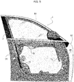
- numeral 1 generally designates a front side door of a motor-vehicle, including a door structure 2.
- the door structure 2 comprises a lower door structure 3 and an upper frame 4 that defines a window opening 5.
- the upper frame 4 includes a front upright and a rear upright protruding upwards from the lower structure 3 of the door, and connected to each other by an upper element (in the example illustrated the front upright and the upper element of the frame 4 are defined by a single continuous curved element).
- the rear upright of the upper frame 4 of the window is intended to be adjacent to a central pillar, or "B" pillar, forming part of the body of the motor-vehicle (and not illustrated here).
- the rear upright of the window frame 4, which is designated by reference number 6, is covered by an aesthetic panel of plastic material 7, which is hooked and/or glued to the sheet metal structure of the upright 6.
- the upright 6, as well as the entire structure of the door is defined by two sheet metal elements 6A, 6B welded together and defining the inner side and the outer side of the upright 6, respectively.
- the aesthetic panel of plastic material 7 is provided with appendices 7A, 7B, for mounting on the upright 6.
- reference G generally designates a window glass that is slidably mounted vertically in the door structure, between a raised position, in which it closes the window opening 5, and a lowered position, in which it is received inside the lower structure 3 of the door.
- a sealing and guiding gasket is mounted on the door structure, serving both to guide the front edge and the rear edge of the glass G during the vertical sliding movement of the glass, and to ensure sealing at the front edge, rear edge and upper edge of the glass G in the raised condition of the glass G.
- the portion of the aforesaid sealing and guiding gasket that cooperates with the rear edge of the glass (in the present description and in the following claims, the terms “front” and “rear” are used with reference to the advancing direction of the motor-vehicle), and which extends along the rear upright 6 of the frame 4 and inside the lower structure 3 of the door, consists of two separate gasket portions.
- An upper gasket portion visible in Figures 2 and 4 and designated by reference 8
- the upper gasket portion 8 extends along the upright 6 of the upper frame 4 of the door, and is secured within a space defined between the upright 6 of the door and the aesthetic panel of plastic material 7. As can be seen in Figure 2 , the upper gasket portion 8 is also hooked onto an aesthetic element of plastic material 10.
- the inner surface of the glass G carries (in the manner that will be described in detail below) a hook-shaped engagement element G1, which is slidably received within a groove 11 defined by a part of the upper portion 8 of the sealing gasket, which is mounted on an inner rib 12 of the aesthetic panel of plastic material 7.
- the arrangement of the engagement element G1 is such so that it keeps the glass G in a position in which the outer surface of the glass G is substantially flush with the outer surface of the aesthetic panel 7 of plastic material.
- the "flush" arrangement of the glass G is an aesthetic quality preferred by car designers.
- the upper portion 8 of the sealing gasket has deformable lips 13, which engage the inner surface and the rear edge of the glass G, to ensure sealing against atmospheric agents, as well as to improve the silence inside the passenger compartment of the motor-vehicle, avoiding rustling air.
- the lips 13 are illustrated in their undeformed inoperative condition, but it is evident that these lips deform with respect to the position illustrated, following engagement with the glass G.
- Figure 4 of the attached drawings shows the upper portion 8, and the lower portion 9, of the part of the sealing and guiding gasket that cooperates with the rear edge of the glass G.
- This Figure also shows the portions 14 and 15 of the sealing gasket that cooperate, respectively, with the upper edge and with the front edge of the glass G.
- the lower portion 9 of the sealing and guiding gasket which cooperates with the rear edge of the glass G, is pre-assembled inside a channel element 16 made of plastic material (visible in perspective view in Figure 6 ), which is then assembled, with the lower portion 9 of the sealing and guiding gasket inserted therein inside the lower structure 3 of the door, as visible in Figure 5 .
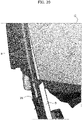
- Figure 5 shows the structure 2 of the door 1, including the inner sheet metal panel 3a forming part of the lower structure 3 of the door.
- Figure 5 also shows the portions 14, 15 of the sealing and guiding gasket, which cooperate with the upper edge and with the front edge of the glass G (illustrated in its raised position), as well as the lower portion 9 of the sealing and guiding gasket, which cooperates with the rear edge of the glass G.
- Figure 5 shows the mounting position of the plastic channel element 16, which internally supports the lower portion 9 of the portion of the gasket that cooperates with the rear edge of the glass G.
- Figure 7 shows a perspective view of the aforesaid lower portion 9 of the sealing and guiding gasket that cooperates with the rear edge of the glass
- Figure 3 shows the channel element 16 made of plastic material in cross-section, with the lower portion 9 of the sealing and guiding gasket mounted therein.
- the channel element 16 comprises an inner side wall 160, an outer side wall 161 and a central wall 162 that connects the side walls 160, 161 to each other.
- the side walls 160, 161 are substantially parallel to the longitudinal vertical plane of the motor-vehicle, while the wall 162 is arranged in a vertical plane substantially transverse with respect to the longitudinal direction of the motor-vehicle.
- the lower portion 9 also has a groove 17 within which an element G2, carried by the inner surface of the glass G, is engaged.
- the groove 17 is defined by a portion of the lower portion 9 of the sealing gasket mounted above an inner rib 18 of the channel element 16.
- the lower portion 9 of the sealing and guiding gasket includes deformable lips 13, arranged to engage the rear edge and the inner surface of the glass G, illustrated in their undeformed condition in Figure 3 .
- the engagement elements G1, G2 are defined by teeth protruding from a profile strip of plastic material 20, glued to the inner surface of the glass G.
- the teeth G1, G2 are spaced apart from each other, and positioned in such a way that the tooth G1 is always engaged within the upper portion 8 of the portion of the sealing and guiding gasket that cooperates with the rear edge of the glass G, both when the glass is in its raised position and when the glass is in its lowered position, or in any intermediate position between said raised and lowered positions.
- the tooth G2 is arranged to be always engaged within the lower portion 9 of the portion of the sealing and guiding gasket, which cooperates with the rear edge of the glass G, both when the glass G is in its raised position and when it is in its lowered position, and when the glass G is in any intermediate position between said raised and lowered positions.
- This condition is clearly visible in Figures 14 and 15 of the attached drawings that show the glass in the lowered position and in the raised position, respectively.
- the channel element 16 within which the lower portion 9 of the gasket is pre-assembled has an upper end portion thereof protruding above the upper end of the gasket portion 9 (see, in particular, Figures 9-11 ).
- the side walls 160, 162 and the central wall 161 have inner surfaces including inclined surface portions 160A, 161 A, 162A, which act as lead surfaces for the correct insertion of the lower-rear corner of the glass G during the assembly maneuver of the glass G in the door
- the lower portion 9 of the sealing gasket that cooperates with the rear edge of the glass G has a cross-section having a general C-shape, with an inner side wall 90, a central wall 91 and an outer side wall 92 which is engaged above the rib 18.
- the inner side wall 90 of the gasket portion 9 is located adjacent to the inner side wall 160 of the channel element 16, and has its top surface adjacent to the lower end of the inclined surface 160A, in such a way that, during insertion of the glass G, the glass slides against the surface 160A until it fits correctly in the channel defined by the gasket portion 9.
- the central wall 91 of the lower gasket portion 9 ( Figure 10 ) is adjacent to the central wall 161 of the channel element 16, and has its top surface adjacent to the lower end of the inclined surface 161A, in such a way that, during insertion of the glass G, the glass is guided until it correctly engages the channel defined by the lower gasket portion 9.
- the outer wall 92 of the lower gasket portion 9 is adjacent to the outer side wall 162 of the channel element 16 ( Figure 11 ).
- the side wall 162 has an inclined surface 162A, which guides the glass G during its downward insertion movement inside the channel element 16, so as to correctly engage it within the channel defined by the lower gasket portion 9.
- the lower portion 9 of the sealing gasket which cooperates with the rear edge of the glass G, is pre-assembled within the channel element 16 before mounting of the channel element 16 within the lower structure 3 of the door.
- the inclined surfaces 160A, 162A create the correct position reference of the glass with respect to the channel element 16, along a horizontal direction transverse with respect to the longitudinal direction of the motor-vehicle (with reference to the mounted condition on the motor-vehicle).
- the inclined surface 161A refers the glass into the correct position with respect to the longitudinal direction of the motor-vehicle.
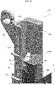
- Figures 16-20 show the different steps of the assembling of the various portions of the sealing gaskets within the structure of the door 1.
- Figure 16 shows the step wherein the channel element 16, inside which the lower gasket portion 9 has been previously assembled, is inside the lower structure 3 of the door.
- Figure 17 shows the final mounting condition of the channel element 16 within the lower structure 3 of the door.
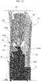
- Figure 18 shows the final condition following a second step of the door assembly, wherein - on the upper frame 4 of the door structure - the upper portion 14 of the sealing gasket intended to cooperate with the upper edge of the glass is assembled, along with the front portion 15 of the sealing gasket intended to cooperate with the front edge of the glass, and the upper portion 8 of the gasket portion intended to cooperate with the rear edge of the glass.
- the glass G is inserted from above into the lower structure 3 of the door, engaging the rear-lower corner of the glass G within the upper end of the channel element 16 (20), in such a way that the inclined guide surfaces 160A, 161A, 162A, which have been described above (see Figures 9-11 ), favor the correct engagement of the glass within the lower portion 9 of the portion of the sealing gasket intended to cooperate with the rear edge of the glass.
- the inner side wall 90 of the lower portion 9 of the sealing gasket has a recess 90A (which in the example illustrated has a V-shape), with a vertical rear side and an inclined front side ("rear” and "front” are always used here with reference to the advancing direction of the motor-vehicle), which makes the operation of inserting the glass G inside the lower portion 9 of the gasket even easier and simpler.
- the invention makes it possible to drastically simplify the assembling operations of the door and, in particular, to facilitate the operation of inserting the glass into the door, always ensuring the mounting of the glass in the correct position. This result is obtained by simple means, without any substantial impact on the complexity and cost of manufacturing (which actually benefits from an increase in productivity).
Landscapes
- Engineering & Computer Science (AREA)
- Mechanical Engineering (AREA)
- Window Of Vehicle (AREA)
- Seal Device For Vehicle (AREA)
Abstract
Description
- The present invention relates to guiding devices for sliding glasses of motor-vehicle side doors, of the type comprising:
- a door structure, including a lower door structure and an upper frame defining a window opening,
- the upper door frame including a door upright which is to be adjacent to a central pillar (or "B" pillar) of the motor-vehicle,
- a sealing and guiding gasket guiding said sliding glass, secured to said door structure and having a portion extending along said door upright and inside the lower door structure,
- an aesthetic panel of plastic material, secured to said door upright, on an outer side thereof,
- a glass slidably mounted vertically within the door structure between a raised closed position in which it closes the window opening and a lowered position in which the glass is received within the lower door structure,
- wherein the glass has an inner surface carrying at least two spaced apart engagement elements, which are slidably engaged within said guiding and sealing gasket, in such a way that in the raised position of the glass, said glass has its outer surface that is flush with the outer surface of said aesthetic panel of plastic material.
- A device for guiding a sliding glass having all the above characteristics is known, for example, from document
WO 2016 174315 A1 . Known solutions of this type have the drawback of requiring relatively complex and difficult operations for assembling the glass on the door structure. - The object of the present invention is to overcome the aforesaid drawback.
- In particular, one object of the invention is to provide a device for guiding a sliding glass wherein the assembling operation of the glass within the door structure is considerably simplified.
- An additional object of the invention is that of producing a guiding device that enables the quality of the assembling operation to be improved, always ensuring that the glass is assembled in the correct position.
- An additional object of the invention is to achieve the aforesaid objectives without making the structure of the motor-vehicle door more complex and expensive.
- In view of achieving one or more of the aforesaid objects, the invention relates to a device for guiding a sliding glass of a motor-vehicle side door having all the characteristics disclosed at the beginning of this description and further characterized in that:
- said portion of the sealing and guiding gasket that extends along said door upright and inside the lower door structure comprises two separate portions:
- an upper gasket portion, which extends along said door upright, and which is secured within a space defined between the door upright and said aesthetic panel of plastic material, and
- a lower gasket portion, which is arranged within said lower door structure, and which is assembled within a channel element of plastic material mounted within said lower door structure,
- said channel element of plastic material has an upper end portion protruding above the upper end of said lower gasket portion, and having inclined inner surfaces configured to guide the insertion of the glass into said lower gasket portion during assembling of the door.
- Studies and tests conducted by the Applicant have shown that the characteristics indicated above, first of all the division into two separate portions of the sealing and guiding gasket portion that extends along the door upright and inside the lower door structure, enables the assembling operation of the glass on the door to be greatly facilitated.
- At the same time, the provision of the lower gasket portion within the aforesaid channel element of plastic material, provided at its upper end with inclined inner surfaces configured to guide the insertion of the glass into the aforesaid lower portion of the sealing and guiding gasket, ensures that the assembling operation can be performed with the certainty that the glass is arranged in the correct assembling position, which further simplifies and facilitates the assembling operation.
- In the preferred embodiment, the guiding device according to the invention is also characterized in that:
- the upper end portion of the plastic channel element has a central wall and two opposite side walls,
- in the mounted condition of said channel element, said side walls are substantially parallel to the longitudinal vertical plane of the motor-vehicle,
- the aforesaid inclined inner surfaces are provided on the inner surfaces of said side walls, to locate the glass in position along the horizontal direction, transverse with respect to the longitudinal direction of the motor-vehicle, as well as on the inner surface of said central wall, to locate the glass in position with respect to the longitudinal direction of the motor-vehicle.
- Also, in the case of the preferred embodiment, the aforesaid channel element of plastic material has a lower end with a stop surface, for engaging the lower end of the aforesaid lower gasket portion.
- According to another characteristic of the present invention, the aforesaid at least two engagement elements carried by the inner surface of the glass are positioned and spaced apart from each other in such a way that each of them is either always engaged with said upper gasket portion, or is always in engagement with said lower gasket portion. In other words, neither of said engagement elements passes from the upper portion to the lower portion of the gasket, or vice versa, during the lowering and raising movements of the glass. This avoids any risk of an engagement element sticking against the upper end of the lower gasket portion, or against the lower end of the upper portion of the gasket during the movements of the glass.
- Further characteristics and advantages of the present invention will become apparent from the description that follows with reference to the attached drawings, provided purely by way of non-limiting example, wherein:
-
Figure 1 illustrates an example of a front side door of a motor-vehicle, -
Figure 2 andFigure 3 are cross-sectional views according to the cross-section lines II-II and III-III ofFigure 1 , which show a preferred examplary embodiment of the guiding device according to the invention, -
Figure 4 is a view that shows only the various portions of the sealing and guiding gasket associated with the door ofFigure 1 , -
Figure 5 is an additional view of the door, which shows the inner structure of the lower portion of the door, -
Figure 6 is a perspective view on an enlarged scale of a channel element made of plastic material, which is arranged in the exemplary embodiment illustrated here to receive the lower portion of the sealing and guiding gasket that is associated with the rear vertical edge (with reference to the direction of travel) of the glass of the door, -
Figure 7 is a perspective view of the aforesaid lower portion of the sealing and guiding gasket portion that cooperates with the rear vertical edge of the glass, -
Figure 8 shows the detail of the upper end of the gasket portion illustrated inFigure 7 , in a perspective view and on an enlarged scale, -
Figure 9 is a perspective view on an enlarged scale of the upper end of the plastic channel element ofFigure 6 , with the lower gasket portion mounted therein, -
Figure 10 is an additional perspective view of the detail ofFigure 9 , -
Figure 11 is yet another perspective view, according to a different direction, of the detail ofFigures 9 and10 , -
Figure 12 illustrates a perspective view on an enlarged scale of the lower end of the plastic channel element ofFigure 6 , with the lower sealing gasket portion mounted therein, -
Figure 13 shows an example of an embodiment of a profiled strip glued to the inner surface of the glass and carrying two engagement elements, spaced apart from each other, which are to cooperate, respectively, with the upper portion and with the lower portion of the sealing and guiding gasket, along the rear vertical edge of the glass, -
Figure 14 is a partial view of the door, showing the glass in its lowered position in order to make it clear that in this position the upper engagement element nevertheless remains engaged within the upper portion of the sealing and guiding gasket, -
Figure 15 is a view corresponding to that ofFigure 14 , which shows the glass in its raised position, in order to make it clear that the lower engagement element carried by the inner surface of the glass nevertheless remains engaged within the lower portion of the sealing and guiding gasket. -
Figure 16 is a view showing a step of the door assembling operation, wherein the channel element of plastic material illustrated inFigure 6 , carrying therein the lower gasket portion that is illustrated inFigure 7 , is assembled within the lower door frame, -
Figure 17 shows a view corresponding to that ofFigure 16 in the condition wherein the aforesaid channel element of plastic material, with the lower portion of the sealing gasket mounted therein, is in its final assembling position within the lower structure of the door, -
Figure 18 shows a step of the door assembling operation, wherein the portions of the sealing and guiding gasket that are associated with the upper frame of the door have been assembled on this frame, -
Figure 19 shows a step wherein the glass of the door is inserted into the lower structure of the door, and -
Figure 20 is a perspective view of a detail showing the engagement of the rear vertical edge of the glass within the lower portion of the sealing and guiding gasket, which is arranged within the aforesaid channel element of plastic material previously mounted within the lower structure of the door. - In the drawings,
numeral 1 generally designates a front side door of a motor-vehicle, including adoor structure 2. Thedoor structure 2 comprises alower door structure 3 and anupper frame 4 that defines awindow opening 5. Theupper frame 4 includes a front upright and a rear upright protruding upwards from thelower structure 3 of the door, and connected to each other by an upper element (in the example illustrated the front upright and the upper element of theframe 4 are defined by a single continuous curved element). - With reference also to
Figure 2 , the rear upright of theupper frame 4 of the window is intended to be adjacent to a central pillar, or "B" pillar, forming part of the body of the motor-vehicle (and not illustrated here). - Still with reference to
Figure 2 , the rear upright of thewindow frame 4, which is designated byreference number 6, is covered by an aesthetic panel ofplastic material 7, which is hooked and/or glued to the sheet metal structure of the upright 6. - With reference, in particular, to
Figure 2 , in the example illustrated, in accordance with a conventional technique, the upright 6, as well as the entire structure of the door, is defined by twosheet metal elements plastic material 7 is provided withappendices - In the drawings, reference G generally designates a window glass that is slidably mounted vertically in the door structure, between a raised position, in which it closes the window opening 5, and a lowered position, in which it is received inside the
lower structure 3 of the door. - In accordance with a conventional technique, a sealing and guiding gasket is mounted on the door structure, serving both to guide the front edge and the rear edge of the glass G during the vertical sliding movement of the glass, and to ensure sealing at the front edge, rear edge and upper edge of the glass G in the raised condition of the glass G.
- According to the invention, the portion of the aforesaid sealing and guiding gasket that cooperates with the rear edge of the glass (in the present description and in the following claims, the terms "front" and "rear" are used with reference to the advancing direction of the motor-vehicle), and which extends along the rear upright 6 of the
frame 4 and inside thelower structure 3 of the door, consists of two separate gasket portions. An upper gasket portion, visible inFigures 2 and4 and designated byreference 8, and a lower gasket portion designated in the drawings byreference 9. Theupper gasket portion 8 extends along the upright 6 of theupper frame 4 of the door, and is secured within a space defined between the upright 6 of the door and the aesthetic panel ofplastic material 7. As can be seen inFigure 2 , theupper gasket portion 8 is also hooked onto an aesthetic element ofplastic material 10. - Referring again to
Figure 2 , the inner surface of the glass G carries (in the manner that will be described in detail below) a hook-shaped engagement element G1, which is slidably received within agroove 11 defined by a part of theupper portion 8 of the sealing gasket, which is mounted on aninner rib 12 of the aesthetic panel ofplastic material 7. - According to a known technique, the arrangement of the engagement element G1 is such so that it keeps the glass G in a position in which the outer surface of the glass G is substantially flush with the outer surface of the
aesthetic panel 7 of plastic material. The "flush" arrangement of the glass G is an aesthetic quality preferred by car designers. - During the vertical sliding of the glass G, the rear edge of the glass is, therefore, not guided directly into the
upper portion 8 of the sealing gasket, but, through the engagement element G1, in order to obtain the aforesaid flush arrangement of the glass. - As can also be seen in
Figure 2 , again in accordance with the prior art, theupper portion 8 of the sealing gasket hasdeformable lips 13, which engage the inner surface and the rear edge of the glass G, to ensure sealing against atmospheric agents, as well as to improve the silence inside the passenger compartment of the motor-vehicle, avoiding rustling air. InFigure 2 , thelips 13 are illustrated in their undeformed inoperative condition, but it is evident that these lips deform with respect to the position illustrated, following engagement with the glass G. -
Figure 4 of the attached drawings shows theupper portion 8, and thelower portion 9, of the part of the sealing and guiding gasket that cooperates with the rear edge of the glass G. This Figure also shows theportions - The
lower portion 9 of the sealing and guiding gasket, which cooperates with the rear edge of the glass G, is pre-assembled inside achannel element 16 made of plastic material (visible in perspective view inFigure 6 ), which is then assembled, with thelower portion 9 of the sealing and guiding gasket inserted therein inside thelower structure 3 of the door, as visible inFigure 5 . -
Figure 5 shows thestructure 2 of thedoor 1, including the inner sheet metal panel 3a forming part of thelower structure 3 of the door.Figure 5 also shows theportions lower portion 9 of the sealing and guiding gasket, which cooperates with the rear edge of the glass G.Figure 5 shows the mounting position of theplastic channel element 16, which internally supports thelower portion 9 of the portion of the gasket that cooperates with the rear edge of the glass G. -
Figure 7 shows a perspective view of the aforesaidlower portion 9 of the sealing and guiding gasket that cooperates with the rear edge of the glass, -
Figure 3 shows thechannel element 16 made of plastic material in cross-section, with thelower portion 9 of the sealing and guiding gasket mounted therein. Thechannel element 16 comprises aninner side wall 160, anouter side wall 161 and acentral wall 162 that connects theside walls side walls wall 162 is arranged in a vertical plane substantially transverse with respect to the longitudinal direction of the motor-vehicle. Like theupper portion 8 of the gasket, thelower portion 9 also has agroove 17 within which an element G2, carried by the inner surface of the glass G, is engaged. Thegroove 17 is defined by a portion of thelower portion 9 of the sealing gasket mounted above aninner rib 18 of thechannel element 16. In this case as well, thelower portion 9 of the sealing and guiding gasket includesdeformable lips 13, arranged to engage the rear edge and the inner surface of the glass G, illustrated in their undeformed condition inFigure 3 . - With reference to
Figure 13 , the engagement elements G1, G2 are defined by teeth protruding from a profile strip ofplastic material 20, glued to the inner surface of the glass G. The teeth G1, G2 are spaced apart from each other, and positioned in such a way that the tooth G1 is always engaged within theupper portion 8 of the portion of the sealing and guiding gasket that cooperates with the rear edge of the glass G, both when the glass is in its raised position and when the glass is in its lowered position, or in any intermediate position between said raised and lowered positions. The tooth G2 is arranged to be always engaged within thelower portion 9 of the portion of the sealing and guiding gasket, which cooperates with the rear edge of the glass G, both when the glass G is in its raised position and when it is in its lowered position, and when the glass G is in any intermediate position between said raised and lowered positions. This condition is clearly visible inFigures 14 and 15 of the attached drawings that show the glass in the lowered position and in the raised position, respectively. - The main advantage of the provision of the portion of the gasket that cooperates with the rear edge of the glass G in an
upper portion 8, and in alower portion 9, separated from each other, consists of a dramatic simplification of the operations for mounting the glass G on the door. In order to further facilitate the assembling operation, thechannel element 16, within which thelower portion 9 of the gasket is pre-assembled, has an upper end portion thereof protruding above the upper end of the gasket portion 9 (see, in particular,Figures 9-11 ). At said upper end portion of thechannel element 16, theside walls central wall 161 have inner surfaces includinginclined surface portions - With reference again to
Figures 3 ,8 and9-11 , thelower portion 9 of the sealing gasket that cooperates with the rear edge of the glass G has a cross-section having a general C-shape, with aninner side wall 90, acentral wall 91 and anouter side wall 92 which is engaged above therib 18. - As can be seen in
Figures 9-11 , in the assembled condition of thelower portion 9 of the sealing gasket inside theplastic channel element 16, theinner side wall 90 of thegasket portion 9 is located adjacent to theinner side wall 160 of thechannel element 16, and has its top surface adjacent to the lower end of theinclined surface 160A, in such a way that, during insertion of the glass G, the glass slides against thesurface 160A until it fits correctly in the channel defined by thegasket portion 9. Similarly, thecentral wall 91 of the lower gasket portion 9 (Figure 10 ) is adjacent to thecentral wall 161 of thechannel element 16, and has its top surface adjacent to the lower end of theinclined surface 161A, in such a way that, during insertion of the glass G, the glass is guided until it correctly engages the channel defined by thelower gasket portion 9. Finally, theouter wall 92 of thelower gasket portion 9 is adjacent to theouter side wall 162 of the channel element 16 (Figure 11 ). Theside wall 162 has aninclined surface 162A, which guides the glass G during its downward insertion movement inside thechannel element 16, so as to correctly engage it within the channel defined by thelower gasket portion 9. - As already indicated above, the
lower portion 9 of the sealing gasket, which cooperates with the rear edge of the glass G, is pre-assembled within thechannel element 16 before mounting of thechannel element 16 within thelower structure 3 of the door. As is evident from the above description, theinclined surfaces channel element 16, along a horizontal direction transverse with respect to the longitudinal direction of the motor-vehicle (with reference to the mounted condition on the motor-vehicle). At the same time, theinclined surface 161A refers the glass into the correct position with respect to the longitudinal direction of the motor-vehicle. Finally, the lower end surface of thelower gasket portion 9 abuts against a lower wall 163 (Figure 12 ) of thechannel element 16, so as to obtain a reference in the correct position of thelower gasket portion 9 within thechannel element 16 with respect to the vertical direction. -
Figures 16-20 show the different steps of the assembling of the various portions of the sealing gaskets within the structure of thedoor 1. -
Figure 16 shows the step wherein thechannel element 16, inside which thelower gasket portion 9 has been previously assembled, is inside thelower structure 3 of the door. -
Figure 17 shows the final mounting condition of thechannel element 16 within thelower structure 3 of the door. -
Figure 18 shows the final condition following a second step of the door assembly, wherein - on theupper frame 4 of the door structure - theupper portion 14 of the sealing gasket intended to cooperate with the upper edge of the glass is assembled, along with thefront portion 15 of the sealing gasket intended to cooperate with the front edge of the glass, and theupper portion 8 of the gasket portion intended to cooperate with the rear edge of the glass. - Once the sealing and guiding gaskets of the glass G have been assembled as such, the glass G is inserted from above into the
lower structure 3 of the door, engaging the rear-lower corner of the glass G within the upper end of the channel element 16 (20), in such a way that the inclined guide surfaces 160A, 161A, 162A, which have been described above (seeFigures 9-11 ), favor the correct engagement of the glass within thelower portion 9 of the portion of the sealing gasket intended to cooperate with the rear edge of the glass. - With reference, in particular, to
Figure 8 , theinner side wall 90 of thelower portion 9 of the sealing gasket has arecess 90A (which in the example illustrated has a V-shape), with a vertical rear side and an inclined front side ("rear" and "front" are always used here with reference to the advancing direction of the motor-vehicle), which makes the operation of inserting the glass G inside thelower portion 9 of the gasket even easier and simpler. - As is evident from the above description, the invention makes it possible to drastically simplify the assembling operations of the door and, in particular, to facilitate the operation of inserting the glass into the door, always ensuring the mounting of the glass in the correct position. This result is obtained by simple means, without any substantial impact on the complexity and cost of manufacturing (which actually benefits from an increase in productivity).
- Naturally, without prejudice to the principle of the invention, the details of construction and the embodiments may vary widely with respect to those described and illustrated purely by way of example, without departing from the scope of the present invention.
Claims (4)
- A device for guiding a sliding glass (G) of a motor-vehicle side door (1), comprising- a door structure (2), including a lower door structure (3) and an upper frame (4) defining a window opening (5),- the upper door frame (4) including a door upright (6) which is to be adjacent to a central pillar of the motor-vehicle,- a sealing and guiding gasket (8, 9, 14, 15) guiding said sliding glass (G), secured to said door structure (2), and having a portion (8, 9) extending along said door upright (6) and inside said lower door structure, (3)- an aesthetic panel of plastic material (7), secured to said door upright (6), on an outer side thereof,- a glass (G) slidably mounted vertically in the door structure (2) between a closed raised position in which it closes the window opening (5) and a lowered position in which the glass (G) is received within the lower door structure (3),- wherein the glass (G) has an inner surface carrying at least two spaced apart engagement elements (G1, G2) that are slidably engaged within said guiding and sealing gasket (8, 9), in such a way that in the raised position of the glass (G), said glass has its outer surface that is flush with the outer surface of said aesthetic panel of plastic material (7),said device being characterized in that:- said part of the sealing and guiding gasket that extends along said door upright (6) and inside the lower door structure (3) comprises two separate portions (8,9):- an upper gasket portion (8), which extends along said door upright (6), and which is secured within a space defined between the door upright (6) and said aesthetic panel of plastic material (7), and- a lower gasket portion (9), which is arranged within said lower door structure (3), and which is assembled within a channel element of plastic material (16) mounted within said lower door structure (3),- said channel element of plastic material (16) has an upper end portion protruding above the upper end of said lower gasket portion (9), and having inclined inner surfaces (160A, 161A, 162A) configured to guide the insertion of the glass (G) into said lower gasket portion (9) during assembling of the door.
- A guiding device according to claim 1, wherein:- the upper end portion of the plastic channel element (16) has a central wall (161) and two opposite side walls (160, 162),- in the mounted condition of said channel element (16), said side walls (160, 162) are substantially parallel to the longitudinal vertical plane of the motor-vehicle,- said inclined inner surfaces (160A, 161A, 162A) are provided on the inner surfaces of said side walls (160, 162), to locate the glass in position along a horizontal direction, transverse with respect to the longitudinal direction of the motor-vehicle, as well as on the inner surface of said central wall (161), to locate the glass (G) in position with respect to the longitudinal direction of the motor-vehicle.
- A guiding device according to claim 1, characterized in that the channel element of plastic material (16) has a lower end with a stop surface (163) for engaging the lower end of the aforesaid lower gasket portion (9), to locate the lower gasket portion (9) in the vertical position with respect to the channel element (16).
- A guiding device according to claim 1, characterized in that said at least two engagement elements (G1, G2) carried by the inner surface of the glass (G) are spaced apart from each other, and positioned in such a way that each of them is always engaged either with said upper gasket portion (8) or with said lower gasket portion (9), respectively.
Priority Applications (2)
| Application Number | Priority Date | Filing Date | Title |
|---|---|---|---|
| EP20203087.0A EP3988356B1 (en) | 2020-10-21 | 2020-10-21 | Device for guiding a sliding glass of a motor-vehicle side door |
| US17/480,597 US11801734B2 (en) | 2020-10-21 | 2021-09-21 | Device for guiding a sliding glass of a motor-vehicle side door |
Applications Claiming Priority (1)
| Application Number | Priority Date | Filing Date | Title |
|---|---|---|---|
| EP20203087.0A EP3988356B1 (en) | 2020-10-21 | 2020-10-21 | Device for guiding a sliding glass of a motor-vehicle side door |
Publications (2)
| Publication Number | Publication Date |
|---|---|
| EP3988356A1 true EP3988356A1 (en) | 2022-04-27 |
| EP3988356B1 EP3988356B1 (en) | 2023-04-12 |
Family
ID=73138606
Family Applications (1)
| Application Number | Title | Priority Date | Filing Date |
|---|---|---|---|
| EP20203087.0A Active EP3988356B1 (en) | 2020-10-21 | 2020-10-21 | Device for guiding a sliding glass of a motor-vehicle side door |
Country Status (2)
| Country | Link |
|---|---|
| US (1) | US11801734B2 (en) |
| EP (1) | EP3988356B1 (en) |
Cited By (1)
| Publication number | Priority date | Publication date | Assignee | Title |
|---|---|---|---|---|
| EP4523936A1 (en) * | 2023-09-04 | 2025-03-19 | Hutchinson (Wuhan) Automotive Rubber Products Co., Ltd. | Outer trim panel, profile assembly, glass run seal, sealing system assembly of window glass, door, and vehicle |
Families Citing this family (6)
| Publication number | Priority date | Publication date | Assignee | Title |
|---|---|---|---|---|
| FR3097169B1 (en) * | 2019-06-17 | 2021-05-28 | Hutchinson | FLUSH WINDOWS MODULE FOR A VEHICLE AND ITS MOUNTING PROCESS |
| PL3907092T3 (en) * | 2020-05-07 | 2023-09-18 | Hutchinson Gmbh | SIDE DOORS OF A MOTOR VEHICLE AND THEIR INSTALLATION METHOD |
| JP7247956B2 (en) * | 2020-05-25 | 2023-03-29 | トヨタ自動車株式会社 | vehicle |
| EP4005837B1 (en) * | 2020-11-25 | 2024-03-27 | HUTCHINSON GmbH | Guide for a sliding glazing |
| WO2022214266A1 (en) * | 2021-04-06 | 2022-10-13 | Bayerische Motoren Werke Aktiengesellschaft | Window regulator for a side window of a motor vehicle |
| CN115538878B (en) * | 2022-11-30 | 2023-03-10 | 宁波天安汽车零部件有限公司 | Vehicle window guide rail assembly |
Citations (5)
| Publication number | Priority date | Publication date | Assignee | Title |
|---|---|---|---|---|
| US20030089044A1 (en) * | 2001-11-15 | 2003-05-15 | Suzuki Motor Corporation | Glass guide construction for vehicular door |
| FR3035034A1 (en) * | 2015-04-20 | 2016-10-21 | Peugeot Citroen Automobiles Sa | DEVICE FOR GUIDING A GLASS ON A MOTOR VEHICLE |
| WO2016174315A1 (en) | 2015-04-28 | 2016-11-03 | Hutchinson | Run seal for vehicle window and sealing module incorporating means for guiding the window in the seal and an element of the door frame |
| WO2018109061A1 (en) * | 2016-12-15 | 2018-06-21 | Jaguar Land Rover Limited | An elongate seal for providing a seal along a movable windowpane for a vehicle |
| US20200307361A1 (en) * | 2019-03-27 | 2020-10-01 | D E Kracht, LLC | Bracket Assembly for a Window of a Vehicle |
Family Cites Families (15)
| Publication number | Priority date | Publication date | Assignee | Title |
|---|---|---|---|---|
| US1609926A (en) * | 1922-04-10 | 1926-12-07 | New England Mfg Company | Runway for sliding glass panes |
| JPS6412914A (en) * | 1987-07-07 | 1989-01-17 | Mazda Motor | Door glass lowering device for vehicle |
| US5943823A (en) * | 1997-02-06 | 1999-08-31 | Om Corporation | Lower sash made of synthetic resin for automotive vehicle door |
| US7624537B2 (en) * | 2002-11-21 | 2009-12-01 | Wagon Automotive Snc | Door of a motor vehicle with a sliding glass panel, and upper kit for door, corresponding method of manufacturing and vehicle |
| FR2847520B1 (en) * | 2002-11-21 | 2006-10-20 | Wagon Automotive Snc | AUTOMOTIVE VEHICLE DOOR WITH SLIDING GLASS PANEL, AND UPPER DOOR ASSEMBLY, METHOD OF MANUFACTURE AND VEHICLE THEREFOR |
| CA2465138C (en) * | 2003-04-23 | 2011-12-13 | Decoma International Inc. | Automotive attachment connector for door window |
| US20080209814A1 (en) * | 2007-03-02 | 2008-09-04 | Timothy Tarjeft | Retainer assembly |
| JP5885156B2 (en) * | 2011-12-22 | 2016-03-15 | 西川ゴム工業株式会社 | Car door glass run retainer and car door structure |
| US8919846B2 (en) * | 2012-05-04 | 2014-12-30 | Srg Global, Inc. | Daylight opening system for vehicle |
| EP3183131B1 (en) * | 2015-11-02 | 2018-07-25 | Cooper Standard GmbH | Window assembly, window pane, and window sealing profile |
| GB2553213B (en) * | 2016-07-19 | 2021-07-21 | Nishikawa Rubber Co Ltd | Glass run |
| JP6731327B2 (en) * | 2016-11-02 | 2020-07-29 | シロキ工業株式会社 | Door frame |
| JP6898768B2 (en) * | 2017-04-27 | 2021-07-07 | 西川ゴム工業株式会社 | Glass run for car doors |
| PL3907092T3 (en) * | 2020-05-07 | 2023-09-18 | Hutchinson Gmbh | SIDE DOORS OF A MOTOR VEHICLE AND THEIR INSTALLATION METHOD |
| EP4005837B1 (en) * | 2020-11-25 | 2024-03-27 | HUTCHINSON GmbH | Guide for a sliding glazing |
-
2020
- 2020-10-21 EP EP20203087.0A patent/EP3988356B1/en active Active
-
2021
- 2021-09-21 US US17/480,597 patent/US11801734B2/en active Active
Patent Citations (5)
| Publication number | Priority date | Publication date | Assignee | Title |
|---|---|---|---|---|
| US20030089044A1 (en) * | 2001-11-15 | 2003-05-15 | Suzuki Motor Corporation | Glass guide construction for vehicular door |
| FR3035034A1 (en) * | 2015-04-20 | 2016-10-21 | Peugeot Citroen Automobiles Sa | DEVICE FOR GUIDING A GLASS ON A MOTOR VEHICLE |
| WO2016174315A1 (en) | 2015-04-28 | 2016-11-03 | Hutchinson | Run seal for vehicle window and sealing module incorporating means for guiding the window in the seal and an element of the door frame |
| WO2018109061A1 (en) * | 2016-12-15 | 2018-06-21 | Jaguar Land Rover Limited | An elongate seal for providing a seal along a movable windowpane for a vehicle |
| US20200307361A1 (en) * | 2019-03-27 | 2020-10-01 | D E Kracht, LLC | Bracket Assembly for a Window of a Vehicle |
Cited By (1)
| Publication number | Priority date | Publication date | Assignee | Title |
|---|---|---|---|---|
| EP4523936A1 (en) * | 2023-09-04 | 2025-03-19 | Hutchinson (Wuhan) Automotive Rubber Products Co., Ltd. | Outer trim panel, profile assembly, glass run seal, sealing system assembly of window glass, door, and vehicle |
Also Published As
| Publication number | Publication date |
|---|---|
| EP3988356B1 (en) | 2023-04-12 |
| US20220118829A1 (en) | 2022-04-21 |
| US11801734B2 (en) | 2023-10-31 |
Similar Documents
| Publication | Publication Date | Title |
|---|---|---|
| EP3988356B1 (en) | Device for guiding a sliding glass of a motor-vehicle side door | |
| US8701349B2 (en) | Guide arrangement for a movable window pane, in particular of a motor vehicle | |
| KR102110198B1 (en) | Vehicle door assembly with insertion area in frame-side guiding element for flat mounted glass concept, and mounting method | |
| US5086589A (en) | Door for vehicles and method for the making of said door | |
| US4240227A (en) | Window assembly for vehicles | |
| US5038521A (en) | Sealing strips | |
| US5040333A (en) | Movable flush-glass system for an automobile door | |
| US9061574B2 (en) | Window frame | |
| US8595981B2 (en) | Sliding window assembly | |
| US20220355654A1 (en) | Flush Window Module for a Vehicle and Method for Mounting Same | |
| US10279667B2 (en) | Seal for automobile door | |
| CN112118980A (en) | Device for guiding a sliding window, glazed vehicle door equipped with said device and vehicle equipped with such a door | |
| US5651578A (en) | Four sided flush sealing system with articulatable pillar | |
| JP2018535865A (en) | Flush glazing device for vehicle door, door, automobile, hermetic device, and corresponding manufacturing method | |
| EP0127591B1 (en) | Guide device for sliding glasses of motor vehicles and method for manufacturing same | |
| US4694611A (en) | Construction of door frame in motor vehicle | |
| US4688847A (en) | Vehicle window installation | |
| US7871120B2 (en) | Four-door motor vehicle having a door sealing system for frameless doors | |
| JP4885988B2 (en) | Door sash | |
| JPS6022198Y2 (en) | automotive glass launch channel | |
| EP0133528B1 (en) | Construction of door in motor vehicle | |
| JP7036673B2 (en) | Vehicle door seal structure | |
| EP0367731A2 (en) | A device for guiding and sealing the vertically movable pane of a motor vehicle window | |
| GB2429027A (en) | Window sealing and guiding arrangements | |
| GB2421268A (en) | Sealing, trimming and finishing strips and vehicle doors incorporating such strips |
Legal Events
| Date | Code | Title | Description |
|---|---|---|---|
| PUAI | Public reference made under article 153(3) epc to a published international application that has entered the european phase |
Free format text: ORIGINAL CODE: 0009012 |
|
| STAA | Information on the status of an ep patent application or granted ep patent |
Free format text: STATUS: REQUEST FOR EXAMINATION WAS MADE |
|
| 17P | Request for examination filed |
Effective date: 20210720 |
|
| AK | Designated contracting states |
Kind code of ref document: A1 Designated state(s): AL AT BE BG CH CY CZ DE DK EE ES FI FR GB GR HR HU IE IS IT LI LT LU LV MC MK MT NL NO PL PT RO RS SE SI SK SM TR |
|
| RIC1 | Information provided on ipc code assigned before grant |
Ipc: B60J 1/17 20060101AFI20221018BHEP |
|
| GRAP | Despatch of communication of intention to grant a patent |
Free format text: ORIGINAL CODE: EPIDOSNIGR1 |
|
| STAA | Information on the status of an ep patent application or granted ep patent |
Free format text: STATUS: GRANT OF PATENT IS INTENDED |
|
| INTG | Intention to grant announced |
Effective date: 20221125 |
|
| GRAS | Grant fee paid |
Free format text: ORIGINAL CODE: EPIDOSNIGR3 |
|
| GRAA | (expected) grant |
Free format text: ORIGINAL CODE: 0009210 |
|
| STAA | Information on the status of an ep patent application or granted ep patent |
Free format text: STATUS: THE PATENT HAS BEEN GRANTED |
|
| AK | Designated contracting states |
Kind code of ref document: B1 Designated state(s): AL AT BE BG CH CY CZ DE DK EE ES FI FR GB GR HR HU IE IS IT LI LT LU LV MC MK MT NL NO PL PT RO RS SE SI SK SM TR |
|
| REG | Reference to a national code |
Ref country code: GB Ref legal event code: FG4D |
|
| REG | Reference to a national code |
Ref country code: CH Ref legal event code: EP |
|
| REG | Reference to a national code |
Ref country code: DE Ref legal event code: R096 Ref document number: 602020009660 Country of ref document: DE |
|
| REG | Reference to a national code |
Ref country code: IE Ref legal event code: FG4D |
|
| REG | Reference to a national code |
Ref country code: AT Ref legal event code: REF Ref document number: 1559575 Country of ref document: AT Kind code of ref document: T Effective date: 20230515 |
|
| REG | Reference to a national code |
Ref country code: LT Ref legal event code: MG9D |
|
| REG | Reference to a national code |
Ref country code: NL Ref legal event code: MP Effective date: 20230412 |
|
| REG | Reference to a national code |
Ref country code: AT Ref legal event code: MK05 Ref document number: 1559575 Country of ref document: AT Kind code of ref document: T Effective date: 20230412 |
|
| PG25 | Lapsed in a contracting state [announced via postgrant information from national office to epo] |
Ref country code: NL Free format text: LAPSE BECAUSE OF FAILURE TO SUBMIT A TRANSLATION OF THE DESCRIPTION OR TO PAY THE FEE WITHIN THE PRESCRIBED TIME-LIMIT Effective date: 20230412 |
|
| PG25 | Lapsed in a contracting state [announced via postgrant information from national office to epo] |
Ref country code: SE Free format text: LAPSE BECAUSE OF FAILURE TO SUBMIT A TRANSLATION OF THE DESCRIPTION OR TO PAY THE FEE WITHIN THE PRESCRIBED TIME-LIMIT Effective date: 20230412 Ref country code: PT Free format text: LAPSE BECAUSE OF FAILURE TO SUBMIT A TRANSLATION OF THE DESCRIPTION OR TO PAY THE FEE WITHIN THE PRESCRIBED TIME-LIMIT Effective date: 20230814 Ref country code: NO Free format text: LAPSE BECAUSE OF FAILURE TO SUBMIT A TRANSLATION OF THE DESCRIPTION OR TO PAY THE FEE WITHIN THE PRESCRIBED TIME-LIMIT Effective date: 20230712 Ref country code: ES Free format text: LAPSE BECAUSE OF FAILURE TO SUBMIT A TRANSLATION OF THE DESCRIPTION OR TO PAY THE FEE WITHIN THE PRESCRIBED TIME-LIMIT Effective date: 20230412 Ref country code: AT Free format text: LAPSE BECAUSE OF FAILURE TO SUBMIT A TRANSLATION OF THE DESCRIPTION OR TO PAY THE FEE WITHIN THE PRESCRIBED TIME-LIMIT Effective date: 20230412 |
|
| RAP4 | Party data changed (patent owner data changed or rights of a patent transferred) |
Owner name: STELLANTIS EUROPE S.P.A. |
|
| PG25 | Lapsed in a contracting state [announced via postgrant information from national office to epo] |
Ref country code: RS Free format text: LAPSE BECAUSE OF FAILURE TO SUBMIT A TRANSLATION OF THE DESCRIPTION OR TO PAY THE FEE WITHIN THE PRESCRIBED TIME-LIMIT Effective date: 20230412 Ref country code: PL Free format text: LAPSE BECAUSE OF FAILURE TO SUBMIT A TRANSLATION OF THE DESCRIPTION OR TO PAY THE FEE WITHIN THE PRESCRIBED TIME-LIMIT Effective date: 20230412 Ref country code: LV Free format text: LAPSE BECAUSE OF FAILURE TO SUBMIT A TRANSLATION OF THE DESCRIPTION OR TO PAY THE FEE WITHIN THE PRESCRIBED TIME-LIMIT Effective date: 20230412 Ref country code: LT Free format text: LAPSE BECAUSE OF FAILURE TO SUBMIT A TRANSLATION OF THE DESCRIPTION OR TO PAY THE FEE WITHIN THE PRESCRIBED TIME-LIMIT Effective date: 20230412 Ref country code: IS Free format text: LAPSE BECAUSE OF FAILURE TO SUBMIT A TRANSLATION OF THE DESCRIPTION OR TO PAY THE FEE WITHIN THE PRESCRIBED TIME-LIMIT Effective date: 20230812 Ref country code: HR Free format text: LAPSE BECAUSE OF FAILURE TO SUBMIT A TRANSLATION OF THE DESCRIPTION OR TO PAY THE FEE WITHIN THE PRESCRIBED TIME-LIMIT Effective date: 20230412 Ref country code: GR Free format text: LAPSE BECAUSE OF FAILURE TO SUBMIT A TRANSLATION OF THE DESCRIPTION OR TO PAY THE FEE WITHIN THE PRESCRIBED TIME-LIMIT Effective date: 20230713 Ref country code: AL Free format text: LAPSE BECAUSE OF FAILURE TO SUBMIT A TRANSLATION OF THE DESCRIPTION OR TO PAY THE FEE WITHIN THE PRESCRIBED TIME-LIMIT Effective date: 20230412 |
|
| PG25 | Lapsed in a contracting state [announced via postgrant information from national office to epo] |
Ref country code: FI Free format text: LAPSE BECAUSE OF FAILURE TO SUBMIT A TRANSLATION OF THE DESCRIPTION OR TO PAY THE FEE WITHIN THE PRESCRIBED TIME-LIMIT Effective date: 20230412 |
|
| REG | Reference to a national code |
Ref country code: DE Ref legal event code: R097 Ref document number: 602020009660 Country of ref document: DE |
|
| PG25 | Lapsed in a contracting state [announced via postgrant information from national office to epo] |
Ref country code: SK Free format text: LAPSE BECAUSE OF FAILURE TO SUBMIT A TRANSLATION OF THE DESCRIPTION OR TO PAY THE FEE WITHIN THE PRESCRIBED TIME-LIMIT Effective date: 20230412 |
|
| PG25 | Lapsed in a contracting state [announced via postgrant information from national office to epo] |
Ref country code: SM Free format text: LAPSE BECAUSE OF FAILURE TO SUBMIT A TRANSLATION OF THE DESCRIPTION OR TO PAY THE FEE WITHIN THE PRESCRIBED TIME-LIMIT Effective date: 20230412 Ref country code: SK Free format text: LAPSE BECAUSE OF FAILURE TO SUBMIT A TRANSLATION OF THE DESCRIPTION OR TO PAY THE FEE WITHIN THE PRESCRIBED TIME-LIMIT Effective date: 20230412 Ref country code: RO Free format text: LAPSE BECAUSE OF FAILURE TO SUBMIT A TRANSLATION OF THE DESCRIPTION OR TO PAY THE FEE WITHIN THE PRESCRIBED TIME-LIMIT Effective date: 20230412 Ref country code: EE Free format text: LAPSE BECAUSE OF FAILURE TO SUBMIT A TRANSLATION OF THE DESCRIPTION OR TO PAY THE FEE WITHIN THE PRESCRIBED TIME-LIMIT Effective date: 20230412 Ref country code: DK Free format text: LAPSE BECAUSE OF FAILURE TO SUBMIT A TRANSLATION OF THE DESCRIPTION OR TO PAY THE FEE WITHIN THE PRESCRIBED TIME-LIMIT Effective date: 20230412 Ref country code: CZ Free format text: LAPSE BECAUSE OF FAILURE TO SUBMIT A TRANSLATION OF THE DESCRIPTION OR TO PAY THE FEE WITHIN THE PRESCRIBED TIME-LIMIT Effective date: 20230412 |
|
| PLBE | No opposition filed within time limit |
Free format text: ORIGINAL CODE: 0009261 |
|
| STAA | Information on the status of an ep patent application or granted ep patent |
Free format text: STATUS: NO OPPOSITION FILED WITHIN TIME LIMIT |
|
| RAP2 | Party data changed (patent owner data changed or rights of a patent transferred) |
Owner name: HUTCHINSON Owner name: STELLANTIS EUROPE S.P.A. |
|
| 26N | No opposition filed |
Effective date: 20240115 |
|
| PG25 | Lapsed in a contracting state [announced via postgrant information from national office to epo] |
Ref country code: SI Free format text: LAPSE BECAUSE OF FAILURE TO SUBMIT A TRANSLATION OF THE DESCRIPTION OR TO PAY THE FEE WITHIN THE PRESCRIBED TIME-LIMIT Effective date: 20230412 |
|
| PLAA | Information modified related to event that no opposition was filed |
Free format text: ORIGINAL CODE: 0009299DELT |
|
| PLBE | No opposition filed within time limit |
Free format text: ORIGINAL CODE: 0009261 |
|
| REG | Reference to a national code |
Ref country code: CH Ref legal event code: PK Free format text: BERICHTIGUNGEN |
|
| PG25 | Lapsed in a contracting state [announced via postgrant information from national office to epo] |
Ref country code: SI Free format text: LAPSE BECAUSE OF FAILURE TO SUBMIT A TRANSLATION OF THE DESCRIPTION OR TO PAY THE FEE WITHIN THE PRESCRIBED TIME-LIMIT Effective date: 20230412 Ref country code: MC Free format text: LAPSE BECAUSE OF FAILURE TO SUBMIT A TRANSLATION OF THE DESCRIPTION OR TO PAY THE FEE WITHIN THE PRESCRIBED TIME-LIMIT Effective date: 20230412 |
|
| REG | Reference to a national code |
Ref country code: CH Ref legal event code: PL |
|
| D26N | No opposition filed (deleted) | ||
| RIN2 | Information on inventor provided after grant (corrected) |
Inventor name: LAJOUX, CYRIL Inventor name: BLOTTIAU, OLIVIER Inventor name: ALTOBELLI, MR. ROBERTO Inventor name: PIGNATA, MR. ERALDO Inventor name: GALLUCCIO, ANTONIO |
|
| 26N | No opposition filed |
Effective date: 20240115 |
|
| REG | Reference to a national code |
Ref country code: BE Ref legal event code: MM Effective date: 20231031 |
|
| PG25 | Lapsed in a contracting state [announced via postgrant information from national office to epo] |
Ref country code: LU Free format text: LAPSE BECAUSE OF NON-PAYMENT OF DUE FEES Effective date: 20231021 |
|
| PG25 | Lapsed in a contracting state [announced via postgrant information from national office to epo] |
Ref country code: LU Free format text: LAPSE BECAUSE OF NON-PAYMENT OF DUE FEES Effective date: 20231021 |
|
| REG | Reference to a national code |
Ref country code: DE Ref legal event code: R081 Ref document number: 602020009660 Country of ref document: DE Owner name: STELLANTIS EUROPE S.P.A., IT Free format text: FORMER OWNER: FCA ITALY S.P.A., TORINO, IT Ref country code: DE Ref legal event code: R081 Ref document number: 602020009660 Country of ref document: DE Owner name: HUTCHINSON, FR Free format text: FORMER OWNER: FCA ITALY S.P.A., TORINO, IT |
|
| REG | Reference to a national code |
Ref country code: DE Ref legal event code: R081 Ref document number: 602020009660 Country of ref document: DE Owner name: STELLANTIS EUROPE S.P.A., IT Free format text: FORMER OWNER: STELLANTIS EUROPE S.P.A., TORINO, IT Ref country code: DE Ref legal event code: R081 Ref document number: 602020009660 Country of ref document: DE Owner name: HUTCHINSON, FR Free format text: FORMER OWNER: STELLANTIS EUROPE S.P.A., TORINO, IT |
|
| PG25 | Lapsed in a contracting state [announced via postgrant information from national office to epo] |
Ref country code: CH Free format text: LAPSE BECAUSE OF NON-PAYMENT OF DUE FEES Effective date: 20231031 |
|
| PG25 | Lapsed in a contracting state [announced via postgrant information from national office to epo] |
Ref country code: CH Free format text: LAPSE BECAUSE OF NON-PAYMENT OF DUE FEES Effective date: 20231031 |
|
| PG25 | Lapsed in a contracting state [announced via postgrant information from national office to epo] |
Ref country code: BE Free format text: LAPSE BECAUSE OF NON-PAYMENT OF DUE FEES Effective date: 20231031 |
|
| PG25 | Lapsed in a contracting state [announced via postgrant information from national office to epo] |
Ref country code: IE Free format text: LAPSE BECAUSE OF NON-PAYMENT OF DUE FEES Effective date: 20231021 |
|
| PG25 | Lapsed in a contracting state [announced via postgrant information from national office to epo] |
Ref country code: IE Free format text: LAPSE BECAUSE OF NON-PAYMENT OF DUE FEES Effective date: 20231021 |
|
| PG25 | Lapsed in a contracting state [announced via postgrant information from national office to epo] |
Ref country code: BG Free format text: LAPSE BECAUSE OF FAILURE TO SUBMIT A TRANSLATION OF THE DESCRIPTION OR TO PAY THE FEE WITHIN THE PRESCRIBED TIME-LIMIT Effective date: 20230412 |
|
| PG25 | Lapsed in a contracting state [announced via postgrant information from national office to epo] |
Ref country code: BG Free format text: LAPSE BECAUSE OF FAILURE TO SUBMIT A TRANSLATION OF THE DESCRIPTION OR TO PAY THE FEE WITHIN THE PRESCRIBED TIME-LIMIT Effective date: 20230412 |
|
| GBPC | Gb: european patent ceased through non-payment of renewal fee |
Effective date: 20241021 |
|
| PG25 | Lapsed in a contracting state [announced via postgrant information from national office to epo] |
Ref country code: GB Free format text: LAPSE BECAUSE OF NON-PAYMENT OF DUE FEES Effective date: 20241021 |
|
| PG25 | Lapsed in a contracting state [announced via postgrant information from national office to epo] |
Ref country code: CY Free format text: LAPSE BECAUSE OF FAILURE TO SUBMIT A TRANSLATION OF THE DESCRIPTION OR TO PAY THE FEE WITHIN THE PRESCRIBED TIME-LIMIT; INVALID AB INITIO Effective date: 20201021 |
|
| PG25 | Lapsed in a contracting state [announced via postgrant information from national office to epo] |
Ref country code: HU Free format text: LAPSE BECAUSE OF FAILURE TO SUBMIT A TRANSLATION OF THE DESCRIPTION OR TO PAY THE FEE WITHIN THE PRESCRIBED TIME-LIMIT; INVALID AB INITIO Effective date: 20201021 |
|
| PGFP | Annual fee paid to national office [announced via postgrant information from national office to epo] |
Ref country code: IT Payment date: 20250923 Year of fee payment: 6 |
|
| PGFP | Annual fee paid to national office [announced via postgrant information from national office to epo] |
Ref country code: FR Payment date: 20250925 Year of fee payment: 6 |
|
| PG25 | Lapsed in a contracting state [announced via postgrant information from national office to epo] |
Ref country code: TR Free format text: LAPSE BECAUSE OF FAILURE TO SUBMIT A TRANSLATION OF THE DESCRIPTION OR TO PAY THE FEE WITHIN THE PRESCRIBED TIME-LIMIT Effective date: 20230412 |
|
| PGFP | Annual fee paid to national office [announced via postgrant information from national office to epo] |
Ref country code: DE Payment date: 20250923 Year of fee payment: 6 |