EP3988262A1 - Safety architecture for an automated work cell - Google Patents
Safety architecture for an automated work cell Download PDFInfo
- Publication number
- EP3988262A1 EP3988262A1 EP21185209.0A EP21185209A EP3988262A1 EP 3988262 A1 EP3988262 A1 EP 3988262A1 EP 21185209 A EP21185209 A EP 21185209A EP 3988262 A1 EP3988262 A1 EP 3988262A1
- Authority
- EP
- European Patent Office
- Prior art keywords
- opening
- panel
- work cell
- cart
- control system
- Prior art date
- Legal status (The legal status is an assumption and is not a legal conclusion. Google has not performed a legal analysis and makes no representation as to the accuracy of the status listed.)
- Granted
Links
Images






Classifications
-
- B—PERFORMING OPERATIONS; TRANSPORTING
- B25—HAND TOOLS; PORTABLE POWER-DRIVEN TOOLS; MANIPULATORS
- B25J—MANIPULATORS; CHAMBERS PROVIDED WITH MANIPULATION DEVICES
- B25J19/00—Accessories fitted to manipulators, e.g. for monitoring, for viewing; Safety devices combined with or specially adapted for use in connection with manipulators
- B25J19/06—Safety devices
-
- B—PERFORMING OPERATIONS; TRANSPORTING
- B25—HAND TOOLS; PORTABLE POWER-DRIVEN TOOLS; MANIPULATORS
- B25J—MANIPULATORS; CHAMBERS PROVIDED WITH MANIPULATION DEVICES
- B25J9/00—Program-controlled manipulators
- B25J9/16—Program controls
- B25J9/1674—Program controls characterised by safety, monitoring, diagnostic
- B25J9/1676—Avoiding collision or forbidden zones
-
- B—PERFORMING OPERATIONS; TRANSPORTING
- B25—HAND TOOLS; PORTABLE POWER-DRIVEN TOOLS; MANIPULATORS
- B25J—MANIPULATORS; CHAMBERS PROVIDED WITH MANIPULATION DEVICES
- B25J15/00—Gripping heads and other end effectors
- B25J15/04—Gripping heads and other end effectors with provision for the remote detachment or exchange of the head or parts thereof
-
- B—PERFORMING OPERATIONS; TRANSPORTING
- B25—HAND TOOLS; PORTABLE POWER-DRIVEN TOOLS; MANIPULATORS
- B25J—MANIPULATORS; CHAMBERS PROVIDED WITH MANIPULATION DEVICES
- B25J19/00—Accessories fitted to manipulators, e.g. for monitoring, for viewing; Safety devices combined with or specially adapted for use in connection with manipulators
- B25J19/0066—Means or methods for maintaining or repairing manipulators
-
- B—PERFORMING OPERATIONS; TRANSPORTING
- B25—HAND TOOLS; PORTABLE POWER-DRIVEN TOOLS; MANIPULATORS
- B25J—MANIPULATORS; CHAMBERS PROVIDED WITH MANIPULATION DEVICES
- B25J21/00—Chambers provided with manipulation devices
-
- B—PERFORMING OPERATIONS; TRANSPORTING
- B25—HAND TOOLS; PORTABLE POWER-DRIVEN TOOLS; MANIPULATORS
- B25J—MANIPULATORS; CHAMBERS PROVIDED WITH MANIPULATION DEVICES
- B25J9/00—Program-controlled manipulators
- B25J9/0084—Program-controlled manipulators comprising a plurality of manipulators
-
- F—MECHANICAL ENGINEERING; LIGHTING; HEATING; WEAPONS; BLASTING
- F16—ENGINEERING ELEMENTS AND UNITS; GENERAL MEASURES FOR PRODUCING AND MAINTAINING EFFECTIVE FUNCTIONING OF MACHINES OR INSTALLATIONS; THERMAL INSULATION IN GENERAL
- F16P—SAFETY DEVICES IN GENERAL; SAFETY DEVICES FOR PRESSES
- F16P3/00—Safety devices acting in conjunction with the control or operation of a machine; Control arrangements requiring the simultaneous use of two or more parts of the body
- F16P3/08—Safety devices acting in conjunction with the control or operation of a machine; Control arrangements requiring the simultaneous use of two or more parts of the body in connection with the locking of doors, covers, guards, or like members giving access to moving machine parts
Definitions
- This disclosure pertains to safety architecture for an automated, robotic work cell that enables safe operator interfaces with motion platforms or positioning machines in the automated, work cell. More specifically, this disclosure pertains to safety architecture for an automated work cell that provides a barrier separating a work cell area from an operator or personnel area. The safety architecture enables personnel to conduct routine interactions with nonfunctioning motion platforms or positioning machines located in the work cell area through openings in the barrier separating the personnel area from the work cell area while other motion platforms or positioning machines in the work cell area continues to function.
- one or more automated motion platforms or positioning machines are employed in the manufacturing of the structural component.
- the motion platforms are controlled by a control system to manipulate end effectors on the motion platforms around the structural component being manufactured.
- the end effectors are operable to perform such tasks as drilling fastener holes at predetermined locations in the structural component, retrieving or vacuuming shavings of the material of the structural component produced by drilling the holes, inserting fasteners into the drilled holes and manipulating the fasteners in order to complete assembly process(es).
- the end effectors and the motion platforms are controlled by the control system to not only perform the manufacturing steps such as drilling holes, but are also controlled by the control system to move about a work cell area in which the structural component is located to perform tasks such as moving to a tool location to deposit a tool at the tool location that had been used by the end effector and replace that tool with a different tool, to move the end effector to a fastener location to obtain a fastener that is then moved by the motion platform and the end effector to a location of a fastener hole in the structural component where the fastener is inserted, to move the motion platform and the end effector to another location to obtain another tool to be used by the end effector to manipulate the fastener in order to complete the assembly process using the tool obtained, etc.
- the movements of the motion platforms and the end effectors on the motion platforms in the work cell area during the manufacturing process of the structural component are controlled by the control system.
- the control system operates autonomously according to a computer program without input from personnel overseeing the manufacturer of the structural component by the automated motion platforms and their end effectors.
- the work cell area occupied by the structural component and the motion platforms and end effectors manufacturing the structural component is surrounded by a safety barrier that is there to prevent personnel from entering the work cell area while the control system is controlling the movements of the motion platforms and their end effectors in manufacturing the structural component.
- Any routine maintenance or repair needed for any of the automated motion platforms and their end effectors, and/or other automated equipment in the work cell area that requires an operator to access the work cell area through the safety barrier requires a complete shut down of all of the automated machinery in the work cell area to ensure the safety of the operator entering the work cell area.
- the operator must enter the work cell area through a safety lockout gated entry system of the safety barrier surrounding the work cell area. The operator must then perform the maintenance or repair activity needed to the automated machines in the work cell area while all of the automated machines in the work cell area remain shut down, whether an automated machine requires maintenance and repair or not.
- the safety architecture of this disclosure provides a barrier separating a robotic work cell area containing a multiple of automated, motion platforms or positioning machines from an operator or personnel area for personnel that maintain the motion platforms or positioning machines in the work cell area.
- the safety architecture enables an operator in the personnel area to conduct routine interactions with a nonfunctioning motion platform or positioning machine located in the work cell area through openings in the barrier, while other motion platforms or positioning machines in the work cell area continue to function.
- access is granted such that a barrier is maintained at all times protecting personnel from the automation that continues to function on the work piece.
- the barrier has several openings through the barrier.
- the openings provide the personnel in the personnel area with access to a nonfunctioning motion platform or positioning machine in the work cell area through the openings while other motion platforms or positioning machines in the work cell area are functioning.
- the access to the work cell area from the personnel area provided by the openings enable the operator to remain in the personnel area external to the work cell area while conducting manual and automated tool changes, loading and removing tool test coupons, recharging lubricant of an end effector on a nonfunctioning motion platform or positioning machine in the work cell area, completing an entire change out or a replacement of an end effector on a nonfunctioning motion platform or positioning machine in the work cell area, etc.
- Panels are positioned over the openings in the barrier.
- the panels are movable between closed positions of the panels where the panels cover over the openings and opened positions of the panels where the panels are displaced from the openings.
- a control system communicates with motion platforms or each positioning machine in the work cell area and with each of the panels.
- the control system is operable to lock a panel in the closed position in response to the control system sensing a functioning motion platform or positioning machine adjacent the opening covered by the panel.
- the control system is also operable to unlock the panel and enable the panel to be moved to the opened position of the panel in response to the control system moving a motion platform or positioning machine adjacent the opening covered by the panel and the control system controlling the motion platform or positioning machine to be nonfunctioning.
- the safety architecture includes a first cart.
- the first cart is manually moveable over a floor surface of the work cell area and personnel area.
- a first cart panel of the panels is secured to the first cart.
- the first cart panel extends vertically upward from the first cart.
- the first cart has a surface that is configured for receiving and supporting an end effector received on the surface of the first cart from a motion platform or positioning machine in the work cell area.
- the first cart is manually moveable from the personnel area through a first opening of the openings through the barrier and into the work cell area to a position in the work cell area where an end effector can be positioned on the surface of the first cart by a motion platform or positioning machine.
- the first cart panel is moved to a closed position of the first cart panel over the first opening in response to the first cart being moved from the personnel area through the first opening and into the work cell area.
- a motion platform or positioning machine can position an end effector needing replacement on the surface of the first cart and then disconnect from the end effector.
- the first cart is moveable from the work cell area through the first opening through the barrier and into the personnel area to remove the end effector from the work cell area.
- the first cart panel is moved to an opened position of the first cart panel where the first cart panel is displaced from the first opening.
- the safety architecture also includes a second cart.
- the second cart is also manually moveable.
- a second cart panel of the panels is secured to the second cart.
- the second cart panel extends vertically upward from the second cart.
- the second cart has a surface that is configured for receiving and supporting an end effector received by the second cart.
- the end effector could be a replacement end effector to replace a disconnected end effector removed from the work cell area such as that discussed above.
- the second cart is moveable from the personnel area through the first opening of the openings through the barrier and into the work cell area. As the second cart is moved from the personnel area through the first opening through the barrier and into the work cell area, the second cart panel is moved over the first opening to a closed position of the second cart panel where the second cart panel covers over the first opening.
- the second cart is also moveable from the work cell area through the first opening through the barrier and into the personnel area. As the second cart is moved from the work cell area through the first opening through the barrier and into the personnel area, the second cart panel is moved to an opened position of the second cart panel where the second cart panel is displaced from the first opening.
- the control system is operable to communicate with the motion platforms or positioning machines in the work cell area and with the first cart panel on the first cart.
- the control system is operable to lock the first cart panel in the closed position of the first cart panel in the first opening through the barrier in response to the control system sensing a functioning motion platform or positioning machine adjacent the first opening through the barrier.
- the control system is operable to unlock the first cart panel enabling the first cart panel to be moved to the open position of the first cart panel in response to the control system controlling the motion platform or positioning machine moved adjacent the first opening to be nonfunctioning.
- the control system is operable to lock and unlock the second cart panel in the same manner as the first cart panel.
- the first opening through the barrier has an upper portion and a lower portion.
- the first cart panel is a lower panel that is configured to cover over the lower portion of the first opening when the first cart panel is moved to the closed position of the first cart panel over the first opening.
- the control system is operable to communicate with the motion platforms or positioning machines in the work cell area and with the first upper panel.
- the control system is operable to lock the first upper panel in the closed position of the first upper panel over the upper portion of the first opening in response to the control system sensing a functioning motion platform or positioning machine having been moved adjacent to the upper portion of the first opening.
- the control system is operable to unlock the first upper panel in the closed position of the first upper panel over the upper portion of the first opening in response to the control system sensing the motion platform or positioning machine having been displaced from adjacent the upper portion of the first opening.
- the barrier There is also a second opening through the barrier, for example a tooling opening.
- the tooling opening provides personnel in the personnel area access to a tool changing location in the work cell area through the tooling opening.
- a second panel for example a tooling panel is positioned over the tooling opening.
- the tooling panel is moveable between a closed position of the tooling panel where the tooling panel covers over the tooling opening and an opened position of the tooling panel where the tooling panel is displaced from the tooling opening.
- the control system communicates with the motion platform or positioning machines in the work cell area and with the tooling panel.
- the control system is operable to lock the tooling panel in the closed position over the tooling opening in response to the control system sensing a functioning motion platform or positioning machine adjacent the tooling opening.
- the control system is also operable to unlock the tooling panel and enable the tooling panel to be moved to the opened position of the tooling panel in response to the control system sensing a nonfunctioning motion platform or positioning machine adjacent the tooling opening.
- test opening provides personnel in the personnel area access to a test coupon location in the work cell area through the test opening.
- a third panel for example is a test panel is positioned over the test opening.
- the test panel is moveable between a closed position of the test panel where the test panel covers over the test opening and an opened position of the test panel where the test panel is displaced from the test opening.
- the control system communicates with the motion platforms or positioning machines in the work cell area and with the test panel.
- the control system is operable to lock the test panel in the closed position over the test opening in response to the control system sensing a functioning motion platform or positioning machine adjacent the test opening.
- the control system is also operable to unlock the test panel and enable the test panel to be moved to the opened position of the test panel in response to the control system sensing a nonfunctioning motion platform or positioning machine adjacent the test opening.
- the safety architecture for an automated work cell of this disclosure eliminates the requirement for an automation cell operator or other personnel to enter an automated, work cell through a monitored gate in a safety barrier surrounding the work cell to conduct routine operations in the maintenance of motion platforms or positioning machines and their end effectors and other automated machines in the work cell.
- the operator remains in a personnel area external to the work cell area while conducting manual and automated tool changes, loading and removing tool test coupons, recharging lubricant of an end effector on a motion platform or positioning machine in the work cell area, completing an entire changeout or a replacement of an end effector on a nonfunctioning motion platform or positioning machine in the work cell area, etc.
- a floor surface 12 of a production facility is represented.
- the machines include a pair of automated, motion platforms or positioning machines 14, 16.
- the motion platforms or positioning machines 14, 16 have end effectors 18, 22(EE) at the ends of arms of the motion platforms or positioning machines 14, 16.
- the structure of the end effectors 18, 22 and the programming of the end effectors is determined to best suit the motion platforms or positioning machines 14, 16 to manufacture a structural component, for example an aircraft component assembly in response to command signals received by the motion platforms or positioning machines 14, 16 from a control system 24 that includes a human/machine interface (HMI).
- HMI human/machine interface
- the safety architecture comprises a barrier 28 on the floor surface 12.
- the barrier 28 extends completely around the positioning machines 14, 16 on the floor surface 12.
- the barrier 28 is a metal mesh or wire screen type barrier that has a height dimension of approximately 6 feet. Other equivalent types of barriers could be employed.
- the barrier 28 extending around the positioning machines 14, 16 on the floor surface 12 separates a work cell area 38 of the floor surface 12 within the barrier 28 from an operator or personnel area 34 outside the barrier 28.
- the personnel area 34 is for personnel or operators that maintain the positioning machines 14, 16 in the work cell area 32.
- the barrier 28 has several openings through a front section of the barrier.
- the openings provide the personnel in the personnel area 34 with access to an immobile, nonfunctioning positioning machine in the work cell area 32 through the openings, while other positioning machines in the work cell area are functioning.
- the access to the work cell area 32 from the personnel area 34 provided by the openings enable an operator or personnel to remain in the personnel area 34 external to the work cell area 32 while conducting manual and automated tool changes, loading and removing tool test coupons, recharging lubricant of an end effector on a nonfunctioning positioning machine in the work cell area 32, completing an entire change out or a replacement of an end effector on a nonfunctioning positioning machine in the work cell area 32, etc.
- This maintenance and/or repair is conducted through the openings provided in the barrier separating the personnel area 34 from the work cell area 32 while other positioning machines in the work cell area continue to function.
- access is granted such that a barrier is maintained at all times protecting personnel from the automation that continues to function on the work piece.
- the openings through the barrier 28 include a cart and end effector opening or a first opening 36 represented by dashed lines in Figure 2 .
- the first opening 36 is actually a lower portion 36 of the first opening, which also includes an upper portion 38 of the first opening.
- the lower portion of the first opening 36 has a rectangular configuration through the barrier 28.
- the lower portion of the first opening 36 extends to the bottom of the barrier 28 with the floor surface 12 defining the bottom of the lower portion of the first opening 36.
- the upper portion of the first opening 38 through the barrier 28 is represented by dashed lines 38 in Figure 2 .
- the safety architecture includes a first cart 42.
- the first cart has a base with a general rectangular configuration.
- the roller devices enable the first cart 42 to be manually moveable over the floor surface 12 in multiple directions.
- the first cart 42 also has a top surface 44 having means for receiving and supporting an end effector.
- a first cart panel 46 is secured to the forward edge of the first cart 42.
- the first cart panel 46 extend vertically upward from the first cart 42.
- the first cart 42 is manually moveable from the personnel area 34 through the lower portion of the first opening 36 in the barrier 28 and into the work cell area 32 to a position of the first cart 42 in the work cell area 32.
- an end effector can be positioned on the top surface 44 of the first cart 42 by a positioning machine or robot 14, 16.
- the first cart panel 46 is moved to a closed position of the first cart panel 46 over the lower portion of the first opening 36.
- a positioning machine 14 can position an end effector 18 needing replacement on the top surface 44 of the first cart 42, and then disconnect from the end effector 18.
- the first cart is manually moveable from the work cell area 32 through the lower portion of the first opening 36 in the barrier 28 and into the personnel area 34 to remove the end effector 18 from the work cell area 32.
- the first cart panel 46 is moved to an opened position of the first cart panel 46 where the first cart panel 46 is displaced from the lower portion of the first opening 36. This leaves the lower portion of the first opening open and accessible.
- the safety architecture also includes a second cart 52.
- the second cart 52 is basically a duplicate of the first cart 42.
- the second cart 52 is also manually moveable.
- a second cart panel 54 is secured to a forward edge of the second cart 52.
- the second cart panel 54 extends vertically upward from the forward edge of the second cart 52 and has a configuration that will close over the lower portion of the first opening 36 when positioned over the lower portion of the first opening.
- the second cart 52 also has a top surface 56 having means for receiving and supporting an end effector 22 received by the second cart 52.
- the end effector 22 could be a replacement end effector to replace a disconnected end effector 18 needing replacement removed from the work cell area 32 such as that discussed above.
- the second cart 52 is manually moveable from the personnel area 32 with the replacement end effector through the lower portion of the first opening 36 in the barrier 28 and into the work cell area 32 to a position where the positioning machine or robot 14 can connect to the replacement end effector.
- the second cart panel 54 is moved over the lower portion of the first opening 36 to a closed position of the second cart panel 54 where the second cart panel 54 covers over the lower portion of the first opening 36.
- the second cart 52 is also manually moveable without the replacement end effector from the work cell area 32 through the lower portion of the first opening 36 in the barrier 28 and into the personnel area 34.
- the second cart panel 54 is moved to an opened position of the second cart panel 54 where the second cart panel 54 is displaced from the lower portion of the first opening 36.
- the control system 24 is operable to communicate with the positioning machines or motion platforms 14, 16 in the work cell area 32 and with the first cart panel 46 on the first cart 42 and the second cart panel 54 on the second cart 52.
- the control system 24 is operable to lock the first cart panel 46 in the closed position of the first cart panel 46 in the lower portion of the first opening 36 in the barrier 28 in response to the control system 24 sensing a mobile, functioning positioning machine or robot 14, 16 adjacent the lower portion of the first opening 36 in the barrier 28.
- the control system 24 is operable to unlock the first cart panel 46 enabling the first cart panel 46 to be moved to the opened position of the first cart panel 46 in response to the control system 24 controlling a positioning machine or robot 14, 16 to move to a position adjacent the lower portion of the first opening 36.
- control system 24 is operable to lock and unlock the second cart panel 54 in the same manner as the first cart panel 46.
- first upper panel 62 or a manual tool change panel (MTC) positioned over the upper portion of the first opening 38.
- the first upper panel 62 is moveable between a closed position of the first upper panel 62 where the first upper panel 62 covers over the upper portion of the first opening 38, and an opened position of the first upper panel 62 where the first upper panel 62 is displaced from the upper portion of the first opening 38.
- MTC manual tool change panel
- the control system 24 positioning the positioning machine or robot 14 and the attached end effector 18 behind the first upper panel 62, the control system 24 can control the positioning machine or robot 14 and end effector 18 to be immobile and nonfunctioning. The immobile and nonfunctioning end effector 18 then can be accessed by personnel from the personnel area 34 for servicing of the end effector 18.
- the control system 24 is operable to communicate with the positioning machines 14, 16 in the work cell area 32 and with the first upper panel 62.
- the control system 24 is operable to lock the first upper panel 62 in the closed position of the first upper panel 62 over the upper portion of the first opening 38 in response to the control system 24 sensing a mobile, functioning positioning machine 14, 16 having been moved adjacent to the upper portion of the first opening 38.
- the control system 24 is operable to unlock the first upper panel 62 in the closed position of the first upper panel 62 over the upper portion of the first opening 38 in response to the control system 24 sensing the positioning machine 14, 16 adjacent the upper portion of the first opening 38 having been controlled by the control system 24 to be immobile and nonfunctioning.
- the second opening 64 is represented by dashed lines in Figure 2 .
- the second opening 64 is, for example, a tooling opening that enables personnel in the personnel area 34 to access a tool changing location behind the second opening 64 in the barrier 28 to position tools in the tool changing location in the work cell area 32 or replace tools from the tool changing location.
- a second panel 66 for example, a tooling panel is positioned over the tooling opening 64.
- the tooling panel 66 is moveable between a closed position of the tooling panel where the tooling panel 66 covers over the tooling opening 64, and an opened position of the tooling panel 66 where the tooling panel is displaced from the tooling opening 64.
- the control system 24 communicates with the positioning machines or motion platforms 14, 16 in the work cell area 32 and with the tooling panel 66.
- the control system 24 is operable to lock the tooling panel 66 in the closed position over the tooling opening 64 in response to the control system 24 sensing a mobile, functioning positioning machine 14, 16 adjacent the tooling opening 64.
- the control system 24 is also operable to unlock the tooling panel 66 and enable the tooling panel to be moved to the opened position of the tooling panel where the tooling panel 66 is displaced from the tooling opening 64 in response to the control system 24 sensing an immobile, nonfunctioning positioning machine adjacent the tooling opening 64.
- a third opening 72 for example, a test coupon opening is provided in the barrier 28. As represented in Figure 2 , the third opening 72 is shown in dashed lines and is positioned just above the second, tooling opening 64. The third opening 72 or test coupon opening enables personnel in the personnel area 34 to access a test coupon holder positioned in the work cell area 32 just behind the test coupon opening 74 to supply material test coupons to the test coupon holder or remove used test coupons from the test coupon holder.
- a third panel for example, a test panel 74 is positioned over the test coupon opening 72.
- the test panel 74 is moveable between a closed position of the test panel where the test panel 74 covers over the test coupon opening 72, and an opened position of the test panel 74 where the test panel is displaced from the test coupon opening 72.
- the control system 24 communicates with the positioning machines or motion platforms 14, 16 in the work cell area 32 and with the test panel 74.
- the control system 24 is operable to lock the test panel 74 in the closed position over the test coupon opening 72 in response to the control system 24 sensing a mobile, functioning positioning machine adjacent the test coupon opening 72.
- the control system 24 is also operable to unlock the test panel 74 and enable the test panel 74 to be moved to the opened position of the test panel 74 displaced from the test coupon opening 72 in response to the control system 24 sensing an immobile, nonfunctioning positioning machine adjacent the test opening 72.
- fastener feed cabinet 82 positioned in the personnel area 34 and separated from the work cell area 32 by the barrier 28.
- the fastener feed cabinet 82 communicates with the work cell area 32 by a fastener feed conveyor 84 that extends from the fastener feed cabinet 82 across the barrier 28 to the work cell area 32.
- the fastener feed cabinet 82 is controlled by the control system 24 to provide needed fasteners to the end effectors 18, 22 in the work cell area 32.
- a vacuum system with a collection canister 92 is positioned in the personnel area 34 and is separated from the work cell area 32 by the barrier 28.
- the vacuum system and collection canister 92 communicate with the end effectors 18, 22 in the work cell area 32.
- the vacuum system and collection canister 92 are controlled by the control system 24 to vacuum material shavings produced by drilling holes in the structural component in the work cell area and collect the shavings in the vacuum system and collection canister 92.
- Positioning the vacuum system and collection canister 92 in the personnel area 32 and separated by the barrier 28 from the work cell area 32 provides personnel access to the canister to dispose of shavings without personnel entering the work cell area 32.
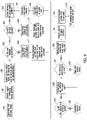
- FIG. 9 is a flow chart representing the operation of the control system 24 when a first end effector 18 (EE) is replaced by a second end effector 22 (EE).
- Step 94 represents a command input to the control system 24 by an operator to replace the first end effector 18 with the second end effector 22.
- a first robot 14 is controlled by the control system 24 to move to a swap position adjacent the lower portion of the first opening 36.
- the first robot 14 is controlled by the control system 24 to shut down the operation of the first end effector 18(EE) and prepare the first end effector 18 for disconnection from the first robot 14.
- the control system 24 checks the position of the first cart 42 to determine if the first cart is positioned properly adjacent the lower portion of the first opening 36.
- the control system 24 controls the first robot 14 to cease operation and wait for the proper positioning of the first cart 42.
- the control system 24 checks to see if the first upper panel 62 (MTC) is closed. If the first upper panel 62 is not closed, the control system 24 controls the operation of the robot 14 to stop until the first upper panel 62 is closed.
- MTC first upper panel 62
- the control system 24 issues a message to a human/machine interface (HMI) of the control system 24 notifying the operator that the first cart 42 is not property positioned adjacent the lower portion of the first opening 36.
- HMI human/machine interface
- the control system 24 issues a (HMI) message to the operator indicating that the first upper panel 62 (MTC) is not in the closed position.
- MTC first upper panel 62
- the operator then manually, properly positions the first cart 42 relative to the lower portion of the first opening 36, and/or closes the first upper panel 62.
- the operator then issues a command to the control system 24 to restart the end effector swap process.
- the robot 14 is moved relative to the lower portion of the first opening 36 where the first robot 14 is ready to swap the first end effector 18 for the second end effector 22.
- the first end effector 18 (EE) is checked to ensure that it is shut down.
- the operator resolves the problem preventing the swap.
- the first robot 14 is controlled by the control system 124 to position the first end effector on the first cart 42.
- the control system 24 checks to see if the first end effector 18 is properly positioned on the first cart 42. If the first end effector 18 is not property positioned on the first cart 42, the operator resolves the problem at step 134. If the first end effector 18 is properly positioned on the first cart 42, the control system 24 controls the first robot 14 to release the first end effector 18 (EE) onto the top surface 44 of the first cart 42 at step 136. At step 138, the first robot 14 moves away from the lower portion of the first opening 36.
- EE first end effector 18
- the control system 24 unlocks the first cart 42 from the lower portion of the first opening 36, and at step 144 the first cart 42 with the removed first end effector 18 (EE) supported on the top surface 44 of the first cart is manually moved out of the lower portion of the first opening 36.
- the second end effector 22 positioned on the top surface 56 of the second cart 52 can be moved into the now open lower portion of the first opening 36 where the first robot 14 can be operated by the control system 24 to connect to the second end effector 22.
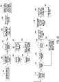
- FIG 10 is a flowchart representing the operation of the control system 24 controlling the first robot 14, the first end effector 18 and the first upper panel 62 during a manual tool change on the first end effector 18.
- a command signal is sent by the control system 24 to the robot 14 that a manual tool change of the end effector 18 is to take place.
- the first robot 14 begins to move to a position adjacent the upper portion of the first opening 38.
- the control system 24 checks to ensure that the first upper panel 62 (MTC) over the upper portion of the first opening 38 is closed.
- the control system 24 determines that the first upper panel 62 is not closed, the control system 24 controls the first robot 14 to stop at a wait position.
- the control system 24 provides a (HMI) signal to the operator indicating that the first upper panel 62 is open and that the first robot 14 cannot proceed with the manual tool change.
- the operator closes the first upper panel 62 and at step 162 the operator controls the control system 24 to restart the movement of the first robot 14.
- the control system 24 again checks to ensure that the first upper panel 62 is closed. With the control system 24 determining that the first upper panel 62 is closed, the first robot 14 moves to a park position with the first end effector 18 positioned adjacent the first upper panel 62.
- the control system 24 places the first robot 14 in a safe stop, and at step 168, the control system 24 unlocks the first upper panel 62 to allow the operator access to the first end effector 18.
- the operator performs the work needed on the first end effector 18 and at step 174 the operator closes the first upper panel 62.
- the operator controls the control system 24 to restart the first robot 14 and at step 178, the control system 24 checks the first upper panel 62 to ensure it is closed. If the control system 24 determines that the first upper panel 62 is not closed, at step 182, the control system 24 issues a (HMI) message notifying the operator that the first upper panel 62 is open and the first robot 14 cannot proceed.
- HMI HMI
- the control system 24 determines that the first upper panel 62 is closed, at step 184 the control system 24 locks the first upper panel 62. At step 186, the control system 24 then takes the first robot 14 out of its safe stop and powers up the robot 14. At step 188, the first robot 14 moves from the park position adjacent the upper portion of the first opening 38 and back to the work cell area 32. At step 192, the first robot 14 is controlled by the control system 24 to return to the work cell area 32.
- FIG 11 is a flowchart representing the operation of the control system 24 controlling a tool changer of the safety architecture in installing or removing changeable tooling of the safety architecture.
- the operator observes the automatic tool changer and determines whether there is a need to install or remove changeable tooling that is controlled by the automatic tool changer.
- the operator presses a button to open the automatic tool changer (ATC) if the operator determines that there is a need to install or remove changeable tooling controlled by the automatic tool changer.
- the control system 24 determines if a command has been received from the robot 14 for a tool change on the robot, and checks the automatic tool changer (ATC) to determine if the automatic tool changer is operating to make a tool change.
- the control system 24 places the automatic tool changer (ATC) in a safe stop.
- the control system 24 unlocks the automatic tool changer (ATC) access door, or the tooling panel 66 covering the second opening 64.
- the operator opens the tooling panel 66 (ATC) and at step 208 the operator performs the needed work on the automatic tool changer, either installing or removing changeable tooling on the automatic tool changer.
- the operator closes the tooling panel 66 (ATC).
- the control system 24 locks the tooling panel 66 (ATC) in its closed position.
- the automatic tool changer (ATC) runs an autoscan to determine the changes made to the changeable tooling operated by the automated tool changer.
- the automatic tool changer communicates to the control system 24 that the tooling change is complete.
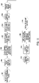
- Figure 12 is a flow chart representing the operation of the control system 24 in supplying and removing test coupons of the safety architecture.
- the control system 24 controls the robot 14 to produce a material test coupon for the aircraft component being constructed in the work cell area 32.
- the control system 24 controls the robot 14 to bring the material test coupon to a position adjacent the third opening 72.
- the control system 24 determines if the third panel 74 is closed at step 226. If the third panel 74 is determined by the control system 24 to not be closed, the control system 24 controls the robot 14 to stop at a wait position at step 228.
- the control system 24 (HMI) notifies the operator that the third panel 74 is open and that the robot 14 has been commanded to stop and not move toward the third opening 72.
- the operator closes the third panel 74 and at step 236, the operator commands the control system 24 to restart the movement of the robot 14.
- the robot 14 again moves toward the third opening 72 and at step 226, the control system 24 again checks to ensure that the third panel 74 is closed. With the control system 24 determining that the third panel 74 is closed, at step 238 the control system 24 locks the third panel 74.
- the robot 14 moves to a position adjacent the third panel 74 and deposits the material test coupon on a coupon holder adjacent the third panel 74.
- the control system 24 then controls the robot 14 to move to a park position, or to move out to the work cell area 32.
- the control system 24 moves the robot 14 to the park location, or to the work cell area 32 to continue the manufacturing operation of the robot 14.
- the control system 24 unlocks the third panel 74.
- the operator opens the third panel 74 and retrieves the material test coupon deposited adjacent the third panel 74.
- the operator communicates to the control system 24 that the material test coupon action has been completed.
Landscapes
- Engineering & Computer Science (AREA)
- Mechanical Engineering (AREA)
- Robotics (AREA)
- General Engineering & Computer Science (AREA)
- Auxiliary Devices For Machine Tools (AREA)
- Manipulator (AREA)
Abstract
Description
- This disclosure pertains to safety architecture for an automated, robotic work cell that enables safe operator interfaces with motion platforms or positioning machines in the automated, work cell. More specifically, this disclosure pertains to safety architecture for an automated work cell that provides a barrier separating a work cell area from an operator or personnel area. The safety architecture enables personnel to conduct routine interactions with nonfunctioning motion platforms or positioning machines located in the work cell area through openings in the barrier separating the personnel area from the work cell area while other motion platforms or positioning machines in the work cell area continues to function.
- In many automated, robotic manufacturing facilities that manufacture large structural components, for example an airplane component assembly, one or more automated motion platforms or positioning machines are employed in the manufacturing of the structural component. The motion platforms are controlled by a control system to manipulate end effectors on the motion platforms around the structural component being manufactured. The end effectors are operable to perform such tasks as drilling fastener holes at predetermined locations in the structural component, retrieving or vacuuming shavings of the material of the structural component produced by drilling the holes, inserting fasteners into the drilled holes and manipulating the fasteners in order to complete assembly process(es). The end effectors and the motion platforms are controlled by the control system to not only perform the manufacturing steps such as drilling holes, but are also controlled by the control system to move about a work cell area in which the structural component is located to perform tasks such as moving to a tool location to deposit a tool at the tool location that had been used by the end effector and replace that tool with a different tool, to move the end effector to a fastener location to obtain a fastener that is then moved by the motion platform and the end effector to a location of a fastener hole in the structural component where the fastener is inserted, to move the motion platform and the end effector to another location to obtain another tool to be used by the end effector to manipulate the fastener in order to complete the assembly process using the tool obtained, etc.
- The movements of the motion platforms and the end effectors on the motion platforms in the work cell area during the manufacturing process of the structural component are controlled by the control system. The control system operates autonomously according to a computer program without input from personnel overseeing the manufacturer of the structural component by the automated motion platforms and their end effectors. The work cell area occupied by the structural component and the motion platforms and end effectors manufacturing the structural component is surrounded by a safety barrier that is there to prevent personnel from entering the work cell area while the control system is controlling the movements of the motion platforms and their end effectors in manufacturing the structural component. Should it be necessary for an operator or other personnel to enter the work cell area through the safety barrier for the purpose of replacing tools in a tool location area in the work cell area, removing shavings accumulated from drilling holes in the material of the structural component, replenishing fasteners that are being used in the manufacture of the structural component or for any other reason related to the manufacture of the structural component by the automated motion platforms and their end effectors, it is necessary that the entire manufacturing process being conducted by the motion platforms and their end effectors inside the barrier surrounding the work cell area be shut down for the safety of the operator passing through the barrier and entering the work cell area.
- Any routine maintenance or repair needed for any of the automated motion platforms and their end effectors, and/or other automated equipment in the work cell area that requires an operator to access the work cell area through the safety barrier requires a complete shut down of all of the automated machinery in the work cell area to ensure the safety of the operator entering the work cell area. The operator must enter the work cell area through a safety lockout gated entry system of the safety barrier surrounding the work cell area. The operator must then perform the maintenance or repair activity needed to the automated machines in the work cell area while all of the automated machines in the work cell area remain shut down, whether an automated machine requires maintenance and repair or not. At the completion of the maintenance or repair activity performed by the operator, it is then necessary to conduct a full work cell area surveillance to ensure that the operator or any other personnel have exited the work cell area through the lockout gate of the barrier surrounding the work cell area to ensure safe operation integrity prior to the control system resuming production activity with the control system controlling the automated motion platforms and their end effectors and other automated equipment in the work cell area in the manufacturing of the structural component in the work cell area.
- The above described need to shut down the operation of all of the automated motion platforms and other automated machines in the work cell area required for an operator or other personnel to enter the work cell area to perform routine maintenance or to repair a machine in the work cell area detracts significantly from the efficiency of the manufacturing operations taking place in the work cell area and significantly increases the time required for the manufacturing of the structural component in the work cell area.
- The safety architecture of this disclosure provides a barrier separating a robotic work cell area containing a multiple of automated, motion platforms or positioning machines from an operator or personnel area for personnel that maintain the motion platforms or positioning machines in the work cell area. The safety architecture enables an operator in the personnel area to conduct routine interactions with a nonfunctioning motion platform or positioning machine located in the work cell area through openings in the barrier, while other motion platforms or positioning machines in the work cell area continue to function. When personnel are accessing a nonfunctioning motion platform or positioning machine, access is granted such that a barrier is maintained at all times protecting personnel from the automation that continues to function on the work piece.
- The barrier has several openings through the barrier. The openings provide the personnel in the personnel area with access to a nonfunctioning motion platform or positioning machine in the work cell area through the openings while other motion platforms or positioning machines in the work cell area are functioning. The access to the work cell area from the personnel area provided by the openings enable the operator to remain in the personnel area external to the work cell area while conducting manual and automated tool changes, loading and removing tool test coupons, recharging lubricant of an end effector on a nonfunctioning motion platform or positioning machine in the work cell area, completing an entire change out or a replacement of an end effector on a nonfunctioning motion platform or positioning machine in the work cell area, etc. through the openings provided in the barrier separating the personnel area from the work cell area while other motion platforms or positioning machines in the work cell area continue to function. Again, when personnel are accessing a nonfunctioning motion platform or positioning machine, access is granted such that a barrier is maintained at all times protecting personnel from the automation that continues to function on the work piece.
- Panels are positioned over the openings in the barrier. The panels are movable between closed positions of the panels where the panels cover over the openings and opened positions of the panels where the panels are displaced from the openings.
- A control system communicates with motion platforms or each positioning machine in the work cell area and with each of the panels. The control system is operable to lock a panel in the closed position in response to the control system sensing a functioning motion platform or positioning machine adjacent the opening covered by the panel. The control system is also operable to unlock the panel and enable the panel to be moved to the opened position of the panel in response to the control system moving a motion platform or positioning machine adjacent the opening covered by the panel and the control system controlling the motion platform or positioning machine to be nonfunctioning.
- The safety architecture includes a first cart. The first cart is manually moveable over a floor surface of the work cell area and personnel area. A first cart panel of the panels is secured to the first cart. The first cart panel extends vertically upward from the first cart. The first cart has a surface that is configured for receiving and supporting an end effector received on the surface of the first cart from a motion platform or positioning machine in the work cell area. The first cart is manually moveable from the personnel area through a first opening of the openings through the barrier and into the work cell area to a position in the work cell area where an end effector can be positioned on the surface of the first cart by a motion platform or positioning machine. As the first cart is moved through the first opening, the first cart panel is moved to a closed position of the first cart panel over the first opening in response to the first cart being moved from the personnel area through the first opening and into the work cell area. With the first cart positioned in the work cell area, a motion platform or positioning machine can position an end effector needing replacement on the surface of the first cart and then disconnect from the end effector. With the end effector supported on the surface of the first cart having been disconnected from the motion platform or positioning machine, the first cart is moveable from the work cell area through the first opening through the barrier and into the personnel area to remove the end effector from the work cell area. As the first cart is moved from the work cell area through the first opening through the barrier and into the personnel area, the first cart panel is moved to an opened position of the first cart panel where the first cart panel is displaced from the first opening.
- The safety architecture also includes a second cart. The second cart is also manually moveable. A second cart panel of the panels is secured to the second cart. The second cart panel extends vertically upward from the second cart. The second cart has a surface that is configured for receiving and supporting an end effector received by the second cart. The end effector could be a replacement end effector to replace a disconnected end effector removed from the work cell area such as that discussed above. The second cart is moveable from the personnel area through the first opening of the openings through the barrier and into the work cell area. As the second cart is moved from the personnel area through the first opening through the barrier and into the work cell area, the second cart panel is moved over the first opening to a closed position of the second cart panel where the second cart panel covers over the first opening. The second cart is also moveable from the work cell area through the first opening through the barrier and into the personnel area. As the second cart is moved from the work cell area through the first opening through the barrier and into the personnel area, the second cart panel is moved to an opened position of the second cart panel where the second cart panel is displaced from the first opening.
- The control system is operable to communicate with the motion platforms or positioning machines in the work cell area and with the first cart panel on the first cart. The control system is operable to lock the first cart panel in the closed position of the first cart panel in the first opening through the barrier in response to the control system sensing a functioning motion platform or positioning machine adjacent the first opening through the barrier. The control system is operable to unlock the first cart panel enabling the first cart panel to be moved to the open position of the first cart panel in response to the control system controlling the motion platform or positioning machine moved adjacent the first opening to be nonfunctioning. The control system is operable to lock and unlock the second cart panel in the same manner as the first cart panel.
- The first opening through the barrier has an upper portion and a lower portion. The first cart panel is a lower panel that is configured to cover over the lower portion of the first opening when the first cart panel is moved to the closed position of the first cart panel over the first opening. There is a first upper panel positioned over the upper portion of the first opening. The first upper panel is moveable between a closed position of the first upper panel where the first upper panel covers over the upper portion of the first opening, and an opened position of the first upper panel where the first upper panel is displaced from the upper portion of the first opening.
- The control system is operable to communicate with the motion platforms or positioning machines in the work cell area and with the first upper panel. The control system is operable to lock the first upper panel in the closed position of the first upper panel over the upper portion of the first opening in response to the control system sensing a functioning motion platform or positioning machine having been moved adjacent to the upper portion of the first opening. The control system is operable to unlock the first upper panel in the closed position of the first upper panel over the upper portion of the first opening in response to the control system sensing the motion platform or positioning machine having been displaced from adjacent the upper portion of the first opening.
- There is also a second opening through the barrier, for example a tooling opening. The tooling opening provides personnel in the personnel area access to a tool changing location in the work cell area through the tooling opening.
- A second panel, for example a tooling panel is positioned over the tooling opening. The tooling panel is moveable between a closed position of the tooling panel where the tooling panel covers over the tooling opening and an opened position of the tooling panel where the tooling panel is displaced from the tooling opening.
- The control system communicates with the motion platform or positioning machines in the work cell area and with the tooling panel. The control system is operable to lock the tooling panel in the closed position over the tooling opening in response to the control system sensing a functioning motion platform or positioning machine adjacent the tooling opening. The control system is also operable to unlock the tooling panel and enable the tooling panel to be moved to the opened position of the tooling panel in response to the control system sensing a nonfunctioning motion platform or positioning machine adjacent the tooling opening.
- There is also a third opening through the barrier, for example a test opening. The test opening provides personnel in the personnel area access to a test coupon location in the work cell area through the test opening.
- A third panel, for example is a test panel is positioned over the test opening. The test panel is moveable between a closed position of the test panel where the test panel covers over the test opening and an opened position of the test panel where the test panel is displaced from the test opening.
- The control system communicates with the motion platforms or positioning machines in the work cell area and with the test panel. The control system is operable to lock the test panel in the closed position over the test opening in response to the control system sensing a functioning motion platform or positioning machine adjacent the test opening. The control system is also operable to unlock the test panel and enable the test panel to be moved to the opened position of the test panel in response to the control system sensing a nonfunctioning motion platform or positioning machine adjacent the test opening.
- The features, functions and advantages that have been discussed can be achieved independently in various embodiments or may be combined in yet other embodiments, further details of which can be seen with reference to the following description and drawings.
- Further features of the safety architecture for an automated work cell and its method of operation are set forth in the following detailed description of the safety architecture and in the following drawing figures.
-
Figure 1 is a representation of a plan view of the safety architecture for an automated work cell of this disclosure. -
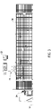
Figure 2 is a representation of a front elevation view of the safety architecture represented inFigure 1 . -
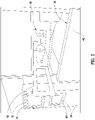
Figure 3 is a representation of a right side elevation view of the safety architecture represented inFigure 1 , with the left side elevation view of the safety architecture being basically a mirror image of the right side elevation view. -
Figure 4 is a representation of a perspective view of a first cart and a second cart of the safety architecture. -
Figure 5 is a representation of a perspective view of a lower portion of a first opening and an upper portion of a first opening in a barrier of the safety architecture. -
Figure 6 is a representation of an elevation view of a second, tool opening and a third, test coupon opening in the barrier of the safety architecture. -
Figure 7 is a representation of an elevation view of a fastener feed cabinet of the safety architecture. -
Figure 8 is a representation of a perspective elevation view of a vacuum system and collection canister of the safety architecture. -
Figure 9 is a flow chart representing operation of a control system during switching out of a first cart and a second cart of the safety architecture. -
Figure 10 is a flow chart representing operation of a control system when changing tooling on an end effector of the safety architecture. -
Figure 11 is a flow chart representing operation of a control system when installing or removing tooling at an automatic tool changer of the safety architecture. -
Figure 12 is a flow chart representing operation of a control system in supplying and removing test coupons of the safety architecture. - The safety architecture for an automated work cell of this disclosure eliminates the requirement for an automation cell operator or other personnel to enter an automated, work cell through a monitored gate in a safety barrier surrounding the work cell to conduct routine operations in the maintenance of motion platforms or positioning machines and their end effectors and other automated machines in the work cell. The operator remains in a personnel area external to the work cell area while conducting manual and automated tool changes, loading and removing tool test coupons, recharging lubricant of an end effector on a motion platform or positioning machine in the work cell area, completing an entire changeout or a replacement of an end effector on a nonfunctioning motion platform or positioning machine in the work cell area, etc. through openings provided in a barrier separating the personnel area from the work cell area while other motion platforms or positioning machines and other automated positioning machines in the work cell area continue to function. This results in the benefits of increased automation operator or personnel safety by reducing exposure of the personnel to functioning automated motion platforms or positioning machines and other automated machines in the work cell area, and reducing critical path machine down time by being able to stage and conduct routine maintenance activities in a more rapid fashion on an automated motion platform or positioning machine or other automated machine while the machine is nonfunctional and while other motion platforms or positioning machines and other automated machines in the work cell area continue to function.
- Referring to
Figure 1 , afloor surface 12 of a production facility is represented. There are a number of automated, machines positioned on thefloor surface 12. The machines include a pair of automated, motion platforms orpositioning machines positioning machines end effectors 18, 22(EE) at the ends of arms of the motion platforms orpositioning machines end effectors positioning machines positioning machines control system 24 that includes a human/machine interface (HMI). Although only two motion platforms orpositioning machines respective end effectors Figures 1 and2 , the safety architecture of this disclosure could also be employed in controlling and maintaining the safety of more than two motion platforms or positioning machines and their associated end effectors. The end effectors 18, 22 could be provided with a variety of different types of tools that would be needed in the manufacture of a structural component, for example drills, cutting tools, grippers, sanders, screwdrivers, spray guns, welders, vacuum tips, etc. All of the automated motion platforms orpositioning machines Figure 1 are described generally as positioning machines herein. - The safety architecture comprises a
barrier 28 on thefloor surface 12. Thebarrier 28 extends completely around thepositioning machines floor surface 12. Thebarrier 28 is a metal mesh or wire screen type barrier that has a height dimension of approximately 6 feet. Other equivalent types of barriers could be employed. Thebarrier 28 extending around thepositioning machines floor surface 12 separates awork cell area 38 of thefloor surface 12 within thebarrier 28 from an operator orpersonnel area 34 outside thebarrier 28. Thepersonnel area 34 is for personnel or operators that maintain thepositioning machines work cell area 32. - The
barrier 28 has several openings through a front section of the barrier. The openings provide the personnel in thepersonnel area 34 with access to an immobile, nonfunctioning positioning machine in thework cell area 32 through the openings, while other positioning machines in the work cell area are functioning. The access to thework cell area 32 from thepersonnel area 34 provided by the openings enable an operator or personnel to remain in thepersonnel area 34 external to thework cell area 32 while conducting manual and automated tool changes, loading and removing tool test coupons, recharging lubricant of an end effector on a nonfunctioning positioning machine in thework cell area 32, completing an entire change out or a replacement of an end effector on a nonfunctioning positioning machine in thework cell area 32, etc. This maintenance and/or repair is conducted through the openings provided in the barrier separating thepersonnel area 34 from thework cell area 32 while other positioning machines in the work cell area continue to function. When personnel are accessing anonfunctioning positioning machine - The openings through the
barrier 28 include a cart and end effector opening or afirst opening 36 represented by dashed lines inFigure 2 . Thefirst opening 36 is actually alower portion 36 of the first opening, which also includes anupper portion 38 of the first opening. The lower portion of thefirst opening 36 has a rectangular configuration through thebarrier 28. The lower portion of thefirst opening 36 extends to the bottom of thebarrier 28 with thefloor surface 12 defining the bottom of the lower portion of thefirst opening 36. The upper portion of thefirst opening 38 through thebarrier 28 is represented by dashedlines 38 inFigure 2 . - The safety architecture includes a
first cart 42. As represented inFigure 4 , the first cart has a base with a general rectangular configuration. There are multidirectional roller devices, for example castors or other equivalent types of roller devices mounted to the bottom of thefirst cart 42. The roller devices enable thefirst cart 42 to be manually moveable over thefloor surface 12 in multiple directions. Thefirst cart 42 also has atop surface 44 having means for receiving and supporting an end effector. For example means for receiving and supporting anend effector 18 needing replacement on the top surface that has been positioned by a positioning machine on thetop surface 44 and disconnected from the positioning machine. As represented inFigure 4 , afirst cart panel 46 is secured to the forward edge of thefirst cart 42. Thefirst cart panel 46 extend vertically upward from thefirst cart 42. - The
first cart 42 is manually moveable from thepersonnel area 34 through the lower portion of thefirst opening 36 in thebarrier 28 and into thework cell area 32 to a position of thefirst cart 42 in thework cell area 32. With thefirst cart 42 positioned in thework cell area 32, an end effector can be positioned on thetop surface 44 of thefirst cart 42 by a positioning machine orrobot first cart 42 is moved through the lower portion of thefirst opening 36, thefirst cart panel 46 is moved to a closed position of thefirst cart panel 46 over the lower portion of thefirst opening 36. With thefirst cart 42 positioned in thework cell area 32, apositioning machine 14 can position anend effector 18 needing replacement on thetop surface 44 of thefirst cart 42, and then disconnect from theend effector 18. With theend effector 18 supported on thetop surface 44 of thefirst cart 42 having been disconnected from thepositioning machine 14, the first cart is manually moveable from thework cell area 32 through the lower portion of thefirst opening 36 in thebarrier 28 and into thepersonnel area 34 to remove theend effector 18 from thework cell area 32. As thefirst cart 42 is manually moved from thework cell area 32 through the lower portion of thefirst opening 36 in thebarrier 28 and into thepersonnel area 34, thefirst cart panel 46 is moved to an opened position of thefirst cart panel 46 where thefirst cart panel 46 is displaced from the lower portion of thefirst opening 36. This leaves the lower portion of the first opening open and accessible. - The safety architecture also includes a
second cart 52. Thesecond cart 52 is basically a duplicate of thefirst cart 42. Thesecond cart 52 is also manually moveable. Asecond cart panel 54 is secured to a forward edge of thesecond cart 52. Thesecond cart panel 54 extends vertically upward from the forward edge of thesecond cart 52 and has a configuration that will close over the lower portion of thefirst opening 36 when positioned over the lower portion of the first opening. Thesecond cart 52 also has atop surface 56 having means for receiving and supporting anend effector 22 received by thesecond cart 52. Theend effector 22 could be a replacement end effector to replace adisconnected end effector 18 needing replacement removed from thework cell area 32 such as that discussed above. Thesecond cart 52 is manually moveable from thepersonnel area 32 with the replacement end effector through the lower portion of thefirst opening 36 in thebarrier 28 and into thework cell area 32 to a position where the positioning machine orrobot 14 can connect to the replacement end effector. As thesecond cart 52 is moved from thepersonnel area 34 through the lower portion of thefirst opening 36 and into thework cell area 32, thesecond cart panel 54 is moved over the lower portion of thefirst opening 36 to a closed position of thesecond cart panel 54 where thesecond cart panel 54 covers over the lower portion of thefirst opening 36. Thesecond cart 52 is also manually moveable without the replacement end effector from thework cell area 32 through the lower portion of thefirst opening 36 in thebarrier 28 and into thepersonnel area 34. As thesecond cart 52 is moved from thework cell area 32 through the lower portion of thefirst opening 36 in thebarrier 28 and into thepersonnel area 34, thesecond cart panel 54 is moved to an opened position of thesecond cart panel 54 where thesecond cart panel 54 is displaced from the lower portion of thefirst opening 36. - The
control system 24 is operable to communicate with the positioning machines ormotion platforms work cell area 32 and with thefirst cart panel 46 on thefirst cart 42 and thesecond cart panel 54 on thesecond cart 52. Thecontrol system 24 is operable to lock thefirst cart panel 46 in the closed position of thefirst cart panel 46 in the lower portion of thefirst opening 36 in thebarrier 28 in response to thecontrol system 24 sensing a mobile, functioning positioning machine orrobot first opening 36 in thebarrier 28. Thecontrol system 24 is operable to unlock thefirst cart panel 46 enabling thefirst cart panel 46 to be moved to the opened position of thefirst cart panel 46 in response to thecontrol system 24 controlling a positioning machine orrobot first opening 36. With thepositioning machine first opening 36, the control system then controls thepositioning machine control system 24 is operable to lock and unlock thesecond cart panel 54 in the same manner as thefirst cart panel 46. - There is a first
upper panel 62, or a manual tool change panel (MTC) positioned over the upper portion of thefirst opening 38. The firstupper panel 62 is moveable between a closed position of the firstupper panel 62 where the firstupper panel 62 covers over the upper portion of thefirst opening 38, and an opened position of the firstupper panel 62 where the firstupper panel 62 is displaced from the upper portion of thefirst opening 38. With the upper portion of thefirst opening 38 positioned directly above the lower portion of thefirst opening 36, there is sufficient area behind the lower portion of thefirst opening 36 and the upper portion of thefirst opening 38 to maneuver a positioning machine orrobot first opening 36 and the upper portion of thefirst opening 38, and position the end effector directly behind the firstupper panel 62. With thecontrol system 24 positioning the positioning machine orrobot 14 and the attachedend effector 18 behind the firstupper panel 62, thecontrol system 24 can control the positioning machine orrobot 14 andend effector 18 to be immobile and nonfunctioning. The immobile andnonfunctioning end effector 18 then can be accessed by personnel from thepersonnel area 34 for servicing of theend effector 18. - The
control system 24 is operable to communicate with thepositioning machines work cell area 32 and with the firstupper panel 62. Thecontrol system 24 is operable to lock the firstupper panel 62 in the closed position of the firstupper panel 62 over the upper portion of thefirst opening 38 in response to thecontrol system 24 sensing a mobile, functioning positioningmachine first opening 38. Thecontrol system 24 is operable to unlock the firstupper panel 62 in the closed position of the firstupper panel 62 over the upper portion of thefirst opening 38 in response to thecontrol system 24 sensing thepositioning machine first opening 38 having been controlled by thecontrol system 24 to be immobile and nonfunctioning. - There is also a second opening through the
barrier 28. Thesecond opening 64 is represented by dashed lines inFigure 2 . Thesecond opening 64 is, for example, a tooling opening that enables personnel in thepersonnel area 34 to access a tool changing location behind thesecond opening 64 in thebarrier 28 to position tools in the tool changing location in thework cell area 32 or replace tools from the tool changing location. - A
second panel 66, for example, a tooling panel is positioned over thetooling opening 64. Thetooling panel 66 is moveable between a closed position of the tooling panel where thetooling panel 66 covers over thetooling opening 64, and an opened position of thetooling panel 66 where the tooling panel is displaced from thetooling opening 64. - The
control system 24 communicates with the positioning machines ormotion platforms work cell area 32 and with thetooling panel 66. Thecontrol system 24 is operable to lock thetooling panel 66 in the closed position over thetooling opening 64 in response to thecontrol system 24 sensing a mobile, functioning positioningmachine tooling opening 64. Thecontrol system 24 is also operable to unlock thetooling panel 66 and enable the tooling panel to be moved to the opened position of the tooling panel where thetooling panel 66 is displaced from thetooling opening 64 in response to thecontrol system 24 sensing an immobile, nonfunctioning positioning machine adjacent thetooling opening 64. - A
third opening 72, for example, a test coupon opening is provided in thebarrier 28. As represented inFigure 2 , thethird opening 72 is shown in dashed lines and is positioned just above the second, toolingopening 64. Thethird opening 72 or test coupon opening enables personnel in thepersonnel area 34 to access a test coupon holder positioned in thework cell area 32 just behind thetest coupon opening 74 to supply material test coupons to the test coupon holder or remove used test coupons from the test coupon holder. - A third panel, for example, a
test panel 74 is positioned over thetest coupon opening 72. Thetest panel 74 is moveable between a closed position of the test panel where thetest panel 74 covers over thetest coupon opening 72, and an opened position of thetest panel 74 where the test panel is displaced from thetest coupon opening 72. - The
control system 24 communicates with the positioning machines ormotion platforms work cell area 32 and with thetest panel 74. Thecontrol system 24 is operable to lock thetest panel 74 in the closed position over thetest coupon opening 72 in response to thecontrol system 24 sensing a mobile, functioning positioning machine adjacent thetest coupon opening 72. Thecontrol system 24 is also operable to unlock thetest panel 74 and enable thetest panel 74 to be moved to the opened position of thetest panel 74 displaced from thetest coupon opening 72 in response to thecontrol system 24 sensing an immobile, nonfunctioning positioning machine adjacent thetest opening 72. - There is a
fastener feed cabinet 82 positioned in thepersonnel area 34 and separated from thework cell area 32 by thebarrier 28. Thefastener feed cabinet 82 communicates with thework cell area 32 by afastener feed conveyor 84 that extends from thefastener feed cabinet 82 across thebarrier 28 to thework cell area 32. Thefastener feed cabinet 82 is controlled by thecontrol system 24 to provide needed fasteners to theend effectors work cell area 32. - A vacuum system with a
collection canister 92 is positioned in thepersonnel area 34 and is separated from thework cell area 32 by thebarrier 28. The vacuum system andcollection canister 92 communicate with theend effectors work cell area 32. The vacuum system andcollection canister 92 are controlled by thecontrol system 24 to vacuum material shavings produced by drilling holes in the structural component in the work cell area and collect the shavings in the vacuum system andcollection canister 92. Positioning the vacuum system andcollection canister 92 in thepersonnel area 32 and separated by thebarrier 28 from thework cell area 32 provides personnel access to the canister to dispose of shavings without personnel entering thework cell area 32. -
Figure 9 is a flow chart representing the operation of thecontrol system 24 when a first end effector 18 (EE) is replaced by a second end effector 22 (EE).Step 94 represents a command input to thecontrol system 24 by an operator to replace thefirst end effector 18 with thesecond end effector 22. At 94 afirst robot 14 is controlled by thecontrol system 24 to move to a swap position adjacent the lower portion of thefirst opening 36. At 98 thefirst robot 14 is controlled by thecontrol system 24 to shut down the operation of the first end effector 18(EE) and prepare thefirst end effector 18 for disconnection from thefirst robot 14. Atstep 102, thecontrol system 24 checks the position of thefirst cart 42 to determine if the first cart is positioned properly adjacent the lower portion of thefirst opening 36. Atstep 104, if thefirst cart 42 is not properly positioned, thecontrol system 24 controls thefirst robot 14 to cease operation and wait for the proper positioning of thefirst cart 42. Atstep 106, thecontrol system 24 checks to see if the first upper panel 62 (MTC) is closed. If the firstupper panel 62 is not closed, thecontrol system 24 controls the operation of therobot 14 to stop until the firstupper panel 62 is closed. - At
step 112, thecontrol system 24 issues a message to a human/machine interface (HMI) of thecontrol system 24 notifying the operator that thefirst cart 42 is not property positioned adjacent the lower portion of thefirst opening 36. Atstep 114, thecontrol system 24 issues a (HMI) message to the operator indicating that the first upper panel 62 (MTC) is not in the closed position. Atstep 116, the operator then manually, properly positions thefirst cart 42 relative to the lower portion of thefirst opening 36, and/or closes the firstupper panel 62. Atstep 118, the operator then issues a command to thecontrol system 24 to restart the end effector swap process. Atstep 122, therobot 14 is moved relative to the lower portion of thefirst opening 36 where thefirst robot 14 is ready to swap thefirst end effector 18 for thesecond end effector 22. - At
step 124, the first end effector 18 (EE) is checked to ensure that it is shut down. Atstep 126, if thefirst end effector 18 is not shut down and ready to be swapped for thesecond end effector 22, the operator resolves the problem preventing the swap. Atstep 128, if thefirst end effector 18 is shut down and is ready to be swapped with thesecond end effector 22, thefirst robot 14 is controlled by thecontrol system 124 to position the first end effector on thefirst cart 42. - At
step 132, thecontrol system 24 checks to see if thefirst end effector 18 is properly positioned on thefirst cart 42. If thefirst end effector 18 is not property positioned on thefirst cart 42, the operator resolves the problem atstep 134. If thefirst end effector 18 is properly positioned on thefirst cart 42, thecontrol system 24 controls thefirst robot 14 to release the first end effector 18 (EE) onto thetop surface 44 of thefirst cart 42 atstep 136. Atstep 138, thefirst robot 14 moves away from the lower portion of thefirst opening 36. Atstep 142, thecontrol system 24 unlocks thefirst cart 42 from the lower portion of thefirst opening 36, and atstep 144 thefirst cart 42 with the removed first end effector 18 (EE) supported on thetop surface 44 of the first cart is manually moved out of the lower portion of thefirst opening 36. With thefirst cart 42 removed from the lower portion of thefirst opening 36, thesecond end effector 22 positioned on thetop surface 56 of thesecond cart 52 can be moved into the now open lower portion of thefirst opening 36 where thefirst robot 14 can be operated by thecontrol system 24 to connect to thesecond end effector 22. -
Figure 10 is a flowchart representing the operation of thecontrol system 24 controlling thefirst robot 14, thefirst end effector 18 and the firstupper panel 62 during a manual tool change on thefirst end effector 18. At step 146 a command signal is sent by thecontrol system 24 to therobot 14 that a manual tool change of theend effector 18 is to take place. Atstep 148, thefirst robot 14 begins to move to a position adjacent the upper portion of thefirst opening 38. Atstep 152 thecontrol system 24 checks to ensure that the first upper panel 62 (MTC) over the upper portion of thefirst opening 38 is closed. Atstep 154, if thecontrol system 24 determines that the firstupper panel 62 is not closed, thecontrol system 24 controls thefirst robot 14 to stop at a wait position. Atstep 156, thecontrol system 24 provides a (HMI) signal to the operator indicating that the firstupper panel 62 is open and that thefirst robot 14 cannot proceed with the manual tool change. Atstep 158, the operator closes the firstupper panel 62 and atstep 162 the operator controls thecontrol system 24 to restart the movement of thefirst robot 14. Again, atstep 148 therobot 14 begins to move to a position adjacent the upper portion of thefirst opening 38 and atstep 152, thecontrol system 24 again checks to ensure that the firstupper panel 62 is closed. With thecontrol system 24 determining that the firstupper panel 62 is closed, thefirst robot 14 moves to a park position with thefirst end effector 18 positioned adjacent the firstupper panel 62. Atstep 166, thecontrol system 24 places thefirst robot 14 in a safe stop, and atstep 168, thecontrol system 24 unlocks the firstupper panel 62 to allow the operator access to thefirst end effector 18. Atstep 172, the operator performs the work needed on thefirst end effector 18 and atstep 174 the operator closes the firstupper panel 62. Atstep 176, the operator controls thecontrol system 24 to restart thefirst robot 14 and atstep 178, thecontrol system 24 checks the firstupper panel 62 to ensure it is closed. If thecontrol system 24 determines that the firstupper panel 62 is not closed, atstep 182, thecontrol system 24 issues a (HMI) message notifying the operator that the firstupper panel 62 is open and thefirst robot 14 cannot proceed. If atstep 178, thecontrol system 24 determines that the firstupper panel 62 is closed, atstep 184 thecontrol system 24 locks the firstupper panel 62. Atstep 186, thecontrol system 24 then takes thefirst robot 14 out of its safe stop and powers up therobot 14. Atstep 188, thefirst robot 14 moves from the park position adjacent the upper portion of thefirst opening 38 and back to thework cell area 32. Atstep 192, thefirst robot 14 is controlled by thecontrol system 24 to return to thework cell area 32. -
Figure 11 is a flowchart representing the operation of thecontrol system 24 controlling a tool changer of the safety architecture in installing or removing changeable tooling of the safety architecture. Atstep 194, the operator observes the automatic tool changer and determines whether there is a need to install or remove changeable tooling that is controlled by the automatic tool changer. Atstep 196, the operator presses a button to open the automatic tool changer (ATC) if the operator determines that there is a need to install or remove changeable tooling controlled by the automatic tool changer. Atstep 198, thecontrol system 24 determines if a command has been received from therobot 14 for a tool change on the robot, and checks the automatic tool changer (ATC) to determine if the automatic tool changer is operating to make a tool change. Atstep 202, thecontrol system 24 places the automatic tool changer (ATC) in a safe stop. Atstep 204, thecontrol system 24 unlocks the automatic tool changer (ATC) access door, or thetooling panel 66 covering thesecond opening 64. Atstep 206, the operator opens the tooling panel 66 (ATC) and atstep 208 the operator performs the needed work on the automatic tool changer, either installing or removing changeable tooling on the automatic tool changer. Atstep 212, the operator closes the tooling panel 66 (ATC). Atstep 214, thecontrol system 24 locks the tooling panel 66 (ATC) in its closed position. Atstep 216, the automatic tool changer (ATC) runs an autoscan to determine the changes made to the changeable tooling operated by the automated tool changer. Atstep 218, the automatic tool changer communicates to thecontrol system 24 that the tooling change is complete. -
Figure 12 is a flow chart representing the operation of thecontrol system 24 in supplying and removing test coupons of the safety architecture. Atstep 222, thecontrol system 24 controls therobot 14 to produce a material test coupon for the aircraft component being constructed in thework cell area 32. Atstep 224, thecontrol system 24 controls therobot 14 to bring the material test coupon to a position adjacent thethird opening 72. As therobot 14 moves toward thethird opening 72, thecontrol system 24 determines if thethird panel 74 is closed atstep 226. If thethird panel 74 is determined by thecontrol system 24 to not be closed, thecontrol system 24 controls therobot 14 to stop at a wait position atstep 228. Atstep 232, the control system 24 (HMI) notifies the operator that thethird panel 74 is open and that therobot 14 has been commanded to stop and not move toward thethird opening 72. Atstep 234, the operator closes thethird panel 74 and atstep 236, the operator commands thecontrol system 24 to restart the movement of therobot 14. Atstep 224, therobot 14 again moves toward thethird opening 72 and atstep 226, thecontrol system 24 again checks to ensure that thethird panel 74 is closed. With thecontrol system 24 determining that thethird panel 74 is closed, atstep 238 thecontrol system 24 locks thethird panel 74. Atstep 242, therobot 14 moves to a position adjacent thethird panel 74 and deposits the material test coupon on a coupon holder adjacent thethird panel 74. Atstep 244, with the material test coupon positioned on the coupon holder, thecontrol system 24 then controls therobot 14 to move to a park position, or to move out to thework cell area 32. Atstep 246, thecontrol system 24 moves therobot 14 to the park location, or to thework cell area 32 to continue the manufacturing operation of therobot 14. Atstep 248, thecontrol system 24 unlocks thethird panel 74. Atstep 252, the operator opens thethird panel 74 and retrieves the material test coupon deposited adjacent thethird panel 74. Atstep 254, the operator communicates to thecontrol system 24 that the material test coupon action has been completed. - Further the disclosure includes examples according to the following clauses:
- Clause 1. Safety architecture for a machine work cell comprising: a
barrier 28 separating awork cell area 32 forpositioning machines personnel area 34 for personnel that maintain the positioning machines in the work cell area; acontrol system 24 communicating with thepositioning machines opening 36 through the barrier, the opening providing personnel in thepersonnel area 34 access through the opening to apositioning machine 14 in thework cell area 32 that has been controlled to move to a position adjacent the opening and then controlled to be immobile and nonfunctioning while other positioning machines in the work cell area are mobile and functioning. - Clause 2. The safety architecture for a machine work cell of clause 1, further comprising: a
panel 46 over theopening 36, the panel being moveable between a closed position of the panel where the panel covers over the opening and an opened position of the panel where the panel is displaced from the opening. - Clause 3. The safety architecture for a machine work cell of clause 1 or 2, further comprising: the
control system 24 having means for communicating withpositioning machines work cell area 32 and with thepanel 46, the control system being operable to lock the panel in the closed position in response to the control system sensing a functioning positioning machine adjacent theopening 36, and the control system being operable to unlock the panel and enable the panel to be moved to the opened position of the panel in response to the control system sensing a positioning machine that has been controlled to move to a position adjacent the opening and then controlled to be immobile and non-functioning. - Clause 4. The safety architecture for a machine work cell of clause 1, 2 or 3, further comprising: the opening 36 being a cart and end effector opening through the
barrier 28; and, atooling opening 64 through thebarrier 28, the tooling opening providing personnel in thepersonnel area 34 access to a tool changing location in thework cell area 32 through the tooling opening. - Clause 5. The safety architecture for a machine work cell of any of clauses 1 to 4, further comprising: the opening 36 being a cart and end effector opening through the
barrier 28; and, atest coupon opening 72 through thebarrier 28, the test coupon opening providing personnel in thepersonnel area 34 access to a test coupon location in thework cell area 32 through the test coupon opening. - Clause 6. The safety architecture for a machine work cell of clause 4 or 5, further comprising: a
test coupon opening 72 through thebarrier 28, the test coupon opening providing personnel in thepersonal area 34 access to a test coupon location in thework cell area 32 through the test coupon opening; the panel being a manualtool change panel 62 over the cart andend effector opening 36; atooling panel 66 over thetooling opening 64, the tooling panel being moveable between a closed position of the tooling panel where the tooling panel covers over the tooling opening and an opened position of the tooling panel where the tooling panel is displaced from the tooling opening; and, atest panel 74 over thetest coupon opening 72, the test panel being moveable between a closed position of the test panel where the test panel covers over the test coupon opening and an opened position of the test panel where the test panel is displaced from the test coupon opening. - Clause 7. The safety architecture for a machine work cell of any of the preceding clauses, further comprising: the
control system 24 having means for communicating withpositioning machines work cell area 32 and with thetooling panel 66, the control system being operable to lock the tooling panel in the closed position over thetooling opening 64 in response to the control system sensing a functioning, mobile positioning machine adjacent the tooling opening, and the control system being operable to unlock the tooling panel and enable the tooling panel to be moved to the opened position of the tooling panel in response to the control system sensing a non-function, immobile positioning machine adjacent the tooling opening; and, thecontrol system 24 having means for communicating withpositioning machines work cell area 32 and with thetest panel 74, the control system being operable to lock the test panel in the closed position over thetest coupon opening 72 in response to the control system sensing a functioning, mobile positioning machine adjacent the test coupon opening, and the control system being operable to unlock the test panel and enable the test panel to be moved to the opened position of the test panel in response to the control system sensing a nonfunctioning, immobile positioning machine adjacent the test coupon opening. - Clause 8. The safety architecture for a machine work cell of any of the preceding clauses, further comprising: a
cart 42, the cart being moveable from thepersonnel area 34 through theopening 36 through thebarrier 28 and into thework cell area 32, and the cart being moveable from the work cell area through the opening through the barrier and into the personnel area; and, the panel being 46 secured to thecart 42 extending vertically upward from the cart. - Clause 9. The safety architecture for a machine work cell of clause 8, further comprising: the
cart 42 havingmeans 44 for receiving and supporting anend effector 18 received by the cart from apositioning machine 14 in thework cell area 32. - Clause 10. The safety architecture for a machine work cell of any of the preceding clauses, further comprising: the opening through the barrier 28 having an upper portion of the opening 38 and a lower portion of the opening 36; the panel 62 being an upper panel; the upper panel 62 being moveable between a closed position of the upper panel where the upper panel covers over the upper portion of the opening 38 and an opened position of the upper panel where the upper panel is displaced from the upper portion of the opening; a lower panel 46 over the lower portion of the opening 36, the lower panel being moveable between a closed position of the lower panel where the lower panel covers over the lower portion of the opening and an opened position of the lower panel where the lower panel is displaced from the lower portion of the opening; and, the control system 24 having means for communicating with positioning machines 14, 16 in the work cell area 32, with the upper panel 62 and with the lower panel 46, the control system being operable to lock the upper panel in the closed position of the upper panel and to lock the lower panel in the closed position of the lower panel in response to the control system sensing a functioning, mobile positioning machine adjacent the upper portion of the opening 38 and adjacent the lower portion of the opening 36.
- Clause 11. Safety architecture for a machine work cell comprising: a barrier 28 separating a work cell area 32 for positioning machines 14, 16 having end effectors 18, 22 on the positioning machines from a personnel area 34 for personnel that maintain the positioning machines in the work cell area; an opening 36 through the barrier 28, the opening providing personnel in the personnel area 34 access through the opening to an immobile, non-function positioning machine 14 connected to an end effector 18 needing replacement in the work cell area 32 and adjacent the opening while other positioning machines in the work cell area are mobile and functioning; a first cart 42, the first cart being moveable from the personnel area 34 through the opening 36 through the barrier 28 and into the work cell area 32, the first cart having a top surface 44 with means for receiving from the positioning machine and supporting the end effector 18 needing replacement on the top surface and the first cart being moveable from the work cell area with the end effector needing replacement through the opening through the barrier and into the personnel area; and, a second cart 52, the second cart having a top surface 56 with means for receiving and supporting a replacement end effector 22 on the top surface, the second cart being moveable from the personnel area 34 with the replacement end effector through the opening 36 through the barrier 28 and into the work cell area 32 to a position where the positioning machine 14 can connect to the replacement end effector, and the second cart being moveable without the replacement end effector from the work cell area through the opening through the barrier and into the personnel area.
-
Clause 12. The safety architecture for a machine work cell of clause 11, further comprising: acontrol system 24 communicating with thepositioning machines control system 24 being operable to control thepositioning machine 14 in thework cell area 32 connected to theend effector 18 needing replacement to move the positioning machine to a position adjacent theopening 36 and then control the positioning machine to be immobile and nonfunctioning. - Clause 13. The safety architecture for a machine work cell of clause 11 or 12, further comprising: a first panel 46 secured to the first cart 42, the first panel extending vertically upward from the first cart, the first panel being moveable over the opening 36 to a closed position of the first panel where the first panel covers over the opening in response to the first cart being moved from the personnel area 34 through the opening through the barrier 28 and into the work cell area 32, and the first panel being moveable to an opened position of the first panel where the first panel is displaced from the opening in response to the first cart being moved from the work cell area through the opening through the barrier and into the personnel area; and, a second panel 54 secured to the second cart 52, the second panel extending vertically upward from the second cart, the second panel being moveable over the opening 36 to a closed position of the second panel where the second panel covers over the opening in response to the second cart being moved from the personnel area 34 through the opening through the barrier 28 and into the work cell area 32, and the second panel being moveable to an opened position of the second panel where the second panel is displaced from the opening in response to the second cart being moved from the work cell area through the opening through the barrier and into the personnel area.
-
Clause 14. The safety architecture for a machine work cell are ofclause 11, 12 or 13, further comprising: thecontrol system 24 having means for communicating with thepositioning machines work cell area 32 and with thefirst panel 46, the control system being operable to lock the first panel in the closed position of the first panel in theopening 36 through thebarrier 28 in response to the control system sensing a mobile and functioning positioning machine adjacent the opening through the barrier, and the control system being operable to unlock the first panel and enable the first panel to be moved to the opened position of the first panel in response to the control system sensing an immobile and nonfunctioning positioning machine adjacent the opening. - Clause 15. The safety architecture for a machine work cell of any of clauses 11 to 14, further comprising: the opening 36 being a cart and end effector opening through the
barrier 28; and, atooling opening 64 through thebarrier 28, the tooling opening providing personnel in thepersonnel area 34 access to a tool changing location in thework cell area 32 through the tooling opening. -
Clause 16. The safety architecture for a machine work cell of clause 15, further comprising: atest coupon opening 72 through thebarrier 28, the test coupon opening providing personnel in thepersonnel area 34 access to a test coupon location in thework cell area 32 through the test coupon opening. - Clause 17. The safety architecture for a machine work cell of
clause 16, further comprising: atooling panel 66 over thetooling opening 64, the tooling panel being moveable between a closed position of the tooling panel where the tooling panel covers over the tooling opening and an opened position of the tooling panel where the tooling panel is displaced from the tooling opening; and, atest panel 74 over thetest coupon opening 72, the test panel being moveable between a closed position of the test panel where the test panel covers over the test coupon opening and an opened position of the test panel where the test panel is displaced from the test coupon opening. -
Clause 18. A method of accessing an end effector on a positioning machine in a work cell area without ceasing functioning of other end effectors of other positioning machines in the work cell area, the method comprising: controlling afirst positioning machine 14 to move afirst end effector 18 to a position adjacent anopening 36 through abarrier 28 separating awork cell area 32 from apersonnel area 34; controlling thefirst positioning machine 14 to hold thefirst end effector 18 stationary in the position adjacent theopening 36 through thebarrier 28; controlling thefirst positioning machine 14 to prevent functioning of thefirst end effector 18 in the position adjacent theopening 36 through thebarrier 28; and, moving apanel 46 closing over theopening 36 through thebarrier 28 away from the opening through the barrier providing personnel access to thefirst end effector 18 in the position adjacent the opening through the barrier without ceasing functioning of other end effectors of other positioning machines in thework cell area 32. - Clause 19. The method of
clause 18, further comprising: controlling thefirst positioning machine 14 to position thefirst end effector 18 on afirst cart 42 that extends through theopening 36 through thebarrier 28; controlling thefirst positioning machine 14 to disconnect from thefirst end effector 18; and, moving thefirst cart 42 and thefirst end effector 18 on the first cart from thework cell area 32 without ceasing operation of the other end effectors of the other positioning machines in the work cell area. - Clause 20. The method of
clause 18 or 19, further comprising: moving asecond cart 52 with asecond end effector 22 positioned on the second cart from thepersonnel area 34 and through theopening 36 through thebarrier 28 to position the second cart and the second end effector on the second cart in thework cell area 32; controlling thefirst positioning machine 14 to attach to thesecond end effector 22 supported on thesecond cart 52 in thework cell area 32; and, controlling thefirst positioning machine 14 to move thesecond end effector 22 attached to the first positioning machine to thework cell area 32 without ceasing functioning of the other end effectors of the other positioning machines in the work cell area. - As various modifications could be made in the construction of the safety architecture and its method of operation herein described and illustrated without departing from the scope of the invention, it is intended that all matter contained in the foregoing description or shown in the accompanying drawings shall be interpreted as illustrative rather than limiting. Thus, the breadth and scope of the present disclosure should not be limited by any of the above described exemplary embodiments, but should be defined only in accordance with the following claims appended hereto and their equivalents.
Claims (15)
- Safety architecture for a machine work cell comprising:a barrier (28) separating a work cell area (32) for positioning machines (14, 16) that are automated manufacturing positioning machines from a personnel area (34) for personnel that maintain the positioning machines in the work cell area;a control system (24) communicating with the positioning machines (14, 16) and controlling movements and functioning of the positioning machines; and,an opening (36) through the barrier, the opening providing personnel in the personnel area (34) access through the opening to a positioning machine (14) in the work cell area (32) that has been controlled to move to a position adjacent the opening and then controlled to be immobile and nonfunctioning while other positioning machines in the work cell area are mobile and functioning.
- The safety architecture for a machine work cell of claim 1, further comprising:
a panel (46) over the opening (36), the panel being moveable between a closed position of the panel where the panel covers over the opening and an opened position of the panel where the panel is displaced from the opening. - The safety architecture for a machine work cell of claim 2, further comprising:
the control system (24) having means for communicating with positioning machines (14, 16) in the work cell area (32) and with the panel (46), the control system being operable to lock the panel in the closed position in response to the control system sensing a functioning positioning machine adjacent the opening (36), and the control system being operable to unlock the panel and enable the panel to be moved to the opened position of the panel in response to the control system sensing a positioning machine that has been controlled to move to a position adjacent the opening and then controlled to be immobile and non-functioning. - The safety architecture for a machine work cell of claim 1, 2 or 3, further comprising:the opening (36) being a cart and end effector opening through the barrier (28); and,a tooling opening (64) through the barrier (28), the tooling opening providing personnel in the personnel area (34) access to a tool changing location in the work cell area (32) through the tooling opening.
- The safety architecture for a machine work cell of claim 1, 2 or 3, further comprising:the opening (36) being a cart and end effector opening through the barrier (28); and,a test coupon opening (72) through the barrier (28), the test coupon opening providing personnel in the personnel area (34) access to a test coupon location in the work cell area (32) through the test coupon opening.
- The safety architecture for a machine work cell of claim 4, further comprising:a test coupon opening (72) through the barrier (28), the test coupon opening providing personnel in the personal area (34) access to a test coupon location in the work cell area (32) through the test coupon opening;the panel being a manual tool change panel (62) over the cart and end effector opening (36);a tooling panel (66) over the tooling opening (64), the tooling panel being moveable between a closed position of the tooling panel where the tooling panel covers over the tooling opening and an opened position of the tooling panel where the tooling panel is displaced from the tooling opening; and,a test panel (74) over the test coupon opening (72), the test panel being moveable between a closed position of the test panel where the test panel covers over the test coupon opening and an opened position of the test panel where the test panel is displaced from the test coupon opening.
- The safety architecture for a machine work cell of claim 6, further comprising:the control system (24) having means for communicating with positioning machines (14, 16) in the work cell area (32) and with the tooling panel (66), the control system being operable to lock the tooling panel in the closed position over the tooling opening (64) in response to the control system sensing a functioning, mobile positioning machine adjacent the tooling opening, and the control system being operable to unlock the tooling panel and enable the tooling panel to be moved to the opened position of the tooling panel in response to the control system sensing a non-function, immobile positioning machine adjacent the tooling opening; and,the control system (24) having means for communicating with positioning machines (14, 16) in the work cell area (32) and with the test panel (74), the control system being operable to lock the test panel in the closed position over the test coupon opening (72) in response to the control system sensing a functioning, mobile positioning machine adjacent the test coupon opening, and the control system being operable to unlock the test panel and enable the test panel to be moved to the opened position of the test panel in response to the control system sensing a nonfunctioning, immobile positioning machine adjacent the test coupon opening.
- The safety architecture for a machine work cell of claim 1, 2 or 3, further comprising:a cart (42), the cart being moveable from the personnel area (34) through the opening (36) through the barrier (28) and into the work cell area (32), and the cart being moveable from the work cell area through the opening through the barrier and into the personnel area; and,the panel being (46) secured to the cart (42) extending vertically upward from the cart.
- The safety architecture for a machine work cell of claim 8, further comprising:
the cart (42) having means (44)for receiving and supporting an end effector (18) received by the cart from a positioning machine (14) in the work cell area (32). - The safety architecture for a machine work cell of claim 1, 2 or 3, further comprising:the opening through the barrier (28) having an upper portion of the opening (38) and a lower portion of the opening (36);the panel (62) being an upper panel;the upper panel (62) being moveable between a closed position of the upper panel where the upper panel covers over the upper portion of the opening (38) and an opened position of the upper panel where the upper panel is displaced from the upper portion of the opening;a lower panel (46) over the lower portion of the opening (36), the lower panel being moveable between a closed position of the lower panel where the lower panel covers over the lower portion of the opening and an opened position of the lower panel where the lower panel is displaced from the lower portion of the opening; and,the control system (24) having means for communicating with positioning machines (14, 16) in the work cell area (32), with the upper panel (62) and with the lower panel (46), the control system being operable to lock the upper panel in the closed position of the upper panel and to lock the lower panel in the closed position of the lower panel in response to the control system sensing a functioning, mobile positioning machine adjacent the upper portion of the opening (38) and adjacent the lower portion of the opening (36).
- The safety architecture for a machine work cell of claim 8, 9 or 10, further comprising:
a second cart (52), the second cart having a top surface (56) with means for receiving and supporting a replacement end effector (22) on the top surface, the second cart being moveable from the personnel area (34) with the replacement end effector through the opening (36) through the barrier (28) and into the work cell area (32) to a position where the positioning machine (14) can connect to the replacement end effector, and the second cart being moveable without the replacement end effector from the work cell area through the opening through the barrier and into the personnel area. - The safety architecture for a machine work cell of claim 11, further comprising:
a second panel (54) secured to the second cart (52), the second panel extending vertically upward from the second cart, the second panel being moveable over the opening (36) to a closed position of the second panel where the second panel covers over the opening in response to the second cart being moved from the personnel area (34) through the opening through the barrier (28) and into the work cell area (32), and the second panel being moveable to an opened position of the second panel where the second panel is displaced from the opening in response to the second cart being moved from the work cell area through the opening through the barrier and into the personnel area. - A method of accessing an end effector on a positioning machine in a work cell area without ceasing functioning of other end effectors of other positioning machines in the work cell area, the method comprising:controlling a first positioning machine (14) to move a first end effector (18) to a position adjacent an opening (36) through a barrier (28) separating a work cell area (32) from a personnel area (34);controlling the first positioning machine (14) to hold the first end effector (18) stationary in the position adjacent the opening (36) through the barrier (28);controlling the first positioning machine (14) to prevent functioning of the first end effector (18) in the position adjacent the opening (36) through the barrier (28); and,moving a panel (46) closing over the opening (36) through the barrier (28) away from the opening through the barrier providing personnel access to the first end effector (18) in the position adjacent the opening through the barrier without ceasing functioning of other end effectors of other positioning machines in the work cell area (32).
- The method of claim 13, further comprising:controlling the first positioning machine (14) to position the first end effector (18) on a first cart (42) that extends through the opening (36) through the barrier (28);controlling the first positioning machine (14) to disconnect from the first end effector (18); and,moving the first cart (42) and the first end effector (18) on the first cart from the work cell area (32) without ceasing operation of the other end effectors of the other positioning machines in the work cell area.
- The method of claim 14, further comprising:moving a second cart (52) with a second end effector (22) positioned on the second cart from the personnel area (34) and through the opening (36) through the barrier (28) to position the second cart and the second end effector on the second cart in the work cell area (32);controlling the first positioning machine (14) to attach to the second end effector (22) supported on the second cart (52) in the work cell area (32); and,controlling the first positioning machine (14) to move the second end effector (22) attached to the first positioning machine to the work cell area (32) without ceasing functioning of the other end effectors of the other positioning machines in the work cell area.
Applications Claiming Priority (1)
| Application Number | Priority Date | Filing Date | Title |
|---|---|---|---|
| US202063094019P | 2020-10-20 | 2020-10-20 |
Publications (2)
| Publication Number | Publication Date |
|---|---|
| EP3988262A1 true EP3988262A1 (en) | 2022-04-27 |
| EP3988262B1 EP3988262B1 (en) | 2024-11-27 |
Family
ID=77179868
Family Applications (1)
| Application Number | Title | Priority Date | Filing Date |
|---|---|---|---|
| EP21185209.0A Active EP3988262B1 (en) | 2020-10-20 | 2021-07-13 | Safety architecture for an automated work cell |
Country Status (2)
| Country | Link |
|---|---|
| US (1) | US12017365B2 (en) |
| EP (1) | EP3988262B1 (en) |
Citations (3)
| Publication number | Priority date | Publication date | Assignee | Title |
|---|---|---|---|---|
| JPH03136790A (en) * | 1989-10-19 | 1991-06-11 | Tokico Ltd | Emergency stop circuit for robot system |
| EP2639019A1 (en) * | 2012-03-16 | 2013-09-18 | Kabushiki Kaisha Yaskawa Denki | Robot system |
| CN205834636U (en) * | 2016-06-30 | 2016-12-28 | 广州市番禺科腾工业有限公司 | Island work station |
Family Cites Families (3)
| Publication number | Priority date | Publication date | Assignee | Title |
|---|---|---|---|---|
| US8514054B2 (en) * | 2010-01-22 | 2013-08-20 | Aramark Uniform & Career Apparell Group, Inc. | Personnel key tracking system |
| WO2015073404A1 (en) * | 2013-11-12 | 2015-05-21 | Comau, Inc. | Assembly line quality control cart and method |
| DE102018218410A1 (en) * | 2018-10-26 | 2020-04-30 | Multivac Sepp Haggenmüller Se & Co. Kg | METHOD AND TOOL TROLLEY FOR TRANSFERING A TOOL COMPONENT |
-
2021
- 2021-07-13 EP EP21185209.0A patent/EP3988262B1/en active Active
- 2021-10-14 US US17/501,649 patent/US12017365B2/en active Active
Patent Citations (3)
| Publication number | Priority date | Publication date | Assignee | Title |
|---|---|---|---|---|
| JPH03136790A (en) * | 1989-10-19 | 1991-06-11 | Tokico Ltd | Emergency stop circuit for robot system |
| EP2639019A1 (en) * | 2012-03-16 | 2013-09-18 | Kabushiki Kaisha Yaskawa Denki | Robot system |
| CN205834636U (en) * | 2016-06-30 | 2016-12-28 | 广州市番禺科腾工业有限公司 | Island work station |
Also Published As
| Publication number | Publication date |
|---|---|
| US12017365B2 (en) | 2024-06-25 |
| EP3988262B1 (en) | 2024-11-27 |
| US20220118620A1 (en) | 2022-04-21 |
Similar Documents
| Publication | Publication Date | Title |
|---|---|---|
| EP1673195B1 (en) | Laser processing installation with integrated loading/unloading of workpieces and laser motion cutting unit mounted on a same rail track | |
| EP2142337B1 (en) | Method and apparatus for installing fasteners | |
| EP2018240B1 (en) | Method for distributed control of a machining tool, in particular a laser machining tool | |
| US6726610B2 (en) | C-frame assembly apparatus and method for large panel-shaped workpieces | |
| EP2323195A1 (en) | Device and method for swapping out a battery in a vehicle | |
| CN117381777B (en) | A switch cabinet autonomous operation robot and method | |
| US5836064A (en) | Machining center | |
| US12017365B2 (en) | Safety architecture for an automated work cell | |
| EP1673198B1 (en) | Laser processing installation with a c-shaped frame and a laser cutting unit with a rest position for servicing | |
| EP2285527A2 (en) | Machine tool with optimally positioned operator station | |
| JP7404464B2 (en) | work stocker | |
| WO2020126830A1 (en) | Method for cleaning an interior of a vehicle, cleaning robot, positioning robot, system and vehicle | |
| JP6915131B1 (en) | Processing machine | |
| CN119910473B (en) | A robot tool magazine with automatic exchange of tool holders of multiple specifications and its control method | |
| EP3854520B1 (en) | Processing system | |
| JP7355472B1 (en) | Machine Tools | |
| KR20220038984A (en) | Control method of Lathe for robot automation | |
| JP2012213837A (en) | Machining device, and method for recovering deposit | |
| US12558775B2 (en) | Robot apparatus and robot system | |
| US12617005B2 (en) | Processing machine | |
| JP7050172B2 (en) | Machine tool and machining machine line | |
| JP2024156423A (en) | Automatic work device and system equipped with the same | |
| JPH03196917A (en) | Processing tank cover device for processing machines | |
| Roche | Automatic riveting cell for commercial airplane floor grid assembly |
Legal Events
| Date | Code | Title | Description |
|---|---|---|---|
| PUAI | Public reference made under article 153(3) epc to a published international application that has entered the european phase |
Free format text: ORIGINAL CODE: 0009012 |
|
| STAA | Information on the status of an ep patent application or granted ep patent |
Free format text: STATUS: THE APPLICATION HAS BEEN PUBLISHED |
|
| AK | Designated contracting states |
Kind code of ref document: A1 Designated state(s): AL AT BE BG CH CY CZ DE DK EE ES FI FR GB GR HR HU IE IS IT LI LT LU LV MC MK MT NL NO PL PT RO RS SE SI SK SM TR |
|
| STAA | Information on the status of an ep patent application or granted ep patent |
Free format text: STATUS: REQUEST FOR EXAMINATION WAS MADE |
|
| 17P | Request for examination filed |
Effective date: 20220825 |
|
| RBV | Designated contracting states (corrected) |
Designated state(s): AL AT BE BG CH CY CZ DE DK EE ES FI FR GB GR HR HU IE IS IT LI LT LU LV MC MK MT NL NO PL PT RO RS SE SI SK SM TR |
|
| RAP3 | Party data changed (applicant data changed or rights of an application transferred) |
Owner name: THE BOEING COMPANY |
|
| GRAP | Despatch of communication of intention to grant a patent |
Free format text: ORIGINAL CODE: EPIDOSNIGR1 |
|
| STAA | Information on the status of an ep patent application or granted ep patent |
Free format text: STATUS: GRANT OF PATENT IS INTENDED |
|
| INTG | Intention to grant announced |
Effective date: 20240625 |
|
| P01 | Opt-out of the competence of the unified patent court (upc) registered |
Free format text: CASE NUMBER: APP_39660/2024 Effective date: 20240703 |
|
| GRAS | Grant fee paid |
Free format text: ORIGINAL CODE: EPIDOSNIGR3 |
|
| GRAA | (expected) grant |
Free format text: ORIGINAL CODE: 0009210 |
|
| STAA | Information on the status of an ep patent application or granted ep patent |
Free format text: STATUS: THE PATENT HAS BEEN GRANTED |
|
| AK | Designated contracting states |
Kind code of ref document: B1 Designated state(s): AL AT BE BG CH CY CZ DE DK EE ES FI FR GB GR HR HU IE IS IT LI LT LU LV MC MK MT NL NO PL PT RO RS SE SI SK SM TR |
|
| REG | Reference to a national code |
Ref country code: GB Ref legal event code: FG4D |
|
| REG | Reference to a national code |
Ref country code: CH Ref legal event code: EP |
|
| REG | Reference to a national code |
Ref country code: DE Ref legal event code: R096 Ref document number: 602021022313 Country of ref document: DE |
|
| REG | Reference to a national code |
Ref country code: IE Ref legal event code: FG4D |
|
| REG | Reference to a national code |
Ref country code: LT Ref legal event code: MG9D |
|
| REG | Reference to a national code |
Ref country code: NL Ref legal event code: MP Effective date: 20241127 |
|
| PG25 | Lapsed in a contracting state [announced via postgrant information from national office to epo] |
Ref country code: PT Free format text: LAPSE BECAUSE OF FAILURE TO SUBMIT A TRANSLATION OF THE DESCRIPTION OR TO PAY THE FEE WITHIN THE PRESCRIBED TIME-LIMIT Effective date: 20250327 Ref country code: IS Free format text: LAPSE BECAUSE OF FAILURE TO SUBMIT A TRANSLATION OF THE DESCRIPTION OR TO PAY THE FEE WITHIN THE PRESCRIBED TIME-LIMIT Effective date: 20250327 Ref country code: HR Free format text: LAPSE BECAUSE OF FAILURE TO SUBMIT A TRANSLATION OF THE DESCRIPTION OR TO PAY THE FEE WITHIN THE PRESCRIBED TIME-LIMIT Effective date: 20241127 |
|
| PG25 | Lapsed in a contracting state [announced via postgrant information from national office to epo] |
Ref country code: FI Free format text: LAPSE BECAUSE OF FAILURE TO SUBMIT A TRANSLATION OF THE DESCRIPTION OR TO PAY THE FEE WITHIN THE PRESCRIBED TIME-LIMIT Effective date: 20241127 Ref country code: NL Free format text: LAPSE BECAUSE OF FAILURE TO SUBMIT A TRANSLATION OF THE DESCRIPTION OR TO PAY THE FEE WITHIN THE PRESCRIBED TIME-LIMIT Effective date: 20241127 |
|
| REG | Reference to a national code |
Ref country code: AT Ref legal event code: MK05 Ref document number: 1745298 Country of ref document: AT Kind code of ref document: T Effective date: 20241127 |
|
| PG25 | Lapsed in a contracting state [announced via postgrant information from national office to epo] |
Ref country code: BG Free format text: LAPSE BECAUSE OF FAILURE TO SUBMIT A TRANSLATION OF THE DESCRIPTION OR TO PAY THE FEE WITHIN THE PRESCRIBED TIME-LIMIT Effective date: 20241127 |
|
| PG25 | Lapsed in a contracting state [announced via postgrant information from national office to epo] |
Ref country code: ES Free format text: LAPSE BECAUSE OF FAILURE TO SUBMIT A TRANSLATION OF THE DESCRIPTION OR TO PAY THE FEE WITHIN THE PRESCRIBED TIME-LIMIT Effective date: 20241127 |
|
| PG25 | Lapsed in a contracting state [announced via postgrant information from national office to epo] |
Ref country code: NO Free format text: LAPSE BECAUSE OF FAILURE TO SUBMIT A TRANSLATION OF THE DESCRIPTION OR TO PAY THE FEE WITHIN THE PRESCRIBED TIME-LIMIT Effective date: 20250227 |
|
| PG25 | Lapsed in a contracting state [announced via postgrant information from national office to epo] |
Ref country code: LV Free format text: LAPSE BECAUSE OF FAILURE TO SUBMIT A TRANSLATION OF THE DESCRIPTION OR TO PAY THE FEE WITHIN THE PRESCRIBED TIME-LIMIT Effective date: 20241127 Ref country code: AT Free format text: LAPSE BECAUSE OF FAILURE TO SUBMIT A TRANSLATION OF THE DESCRIPTION OR TO PAY THE FEE WITHIN THE PRESCRIBED TIME-LIMIT Effective date: 20241127 Ref country code: GR Free format text: LAPSE BECAUSE OF FAILURE TO SUBMIT A TRANSLATION OF THE DESCRIPTION OR TO PAY THE FEE WITHIN THE PRESCRIBED TIME-LIMIT Effective date: 20250228 |
|
| PG25 | Lapsed in a contracting state [announced via postgrant information from national office to epo] |
Ref country code: PL Free format text: LAPSE BECAUSE OF FAILURE TO SUBMIT A TRANSLATION OF THE DESCRIPTION OR TO PAY THE FEE WITHIN THE PRESCRIBED TIME-LIMIT Effective date: 20241127 |
|
| PG25 | Lapsed in a contracting state [announced via postgrant information from national office to epo] |
Ref country code: RS Free format text: LAPSE BECAUSE OF FAILURE TO SUBMIT A TRANSLATION OF THE DESCRIPTION OR TO PAY THE FEE WITHIN THE PRESCRIBED TIME-LIMIT Effective date: 20250227 |
|
| PG25 | Lapsed in a contracting state [announced via postgrant information from national office to epo] |
Ref country code: SM Free format text: LAPSE BECAUSE OF FAILURE TO SUBMIT A TRANSLATION OF THE DESCRIPTION OR TO PAY THE FEE WITHIN THE PRESCRIBED TIME-LIMIT Effective date: 20241127 |
|
| PG25 | Lapsed in a contracting state [announced via postgrant information from national office to epo] |
Ref country code: DK Free format text: LAPSE BECAUSE OF FAILURE TO SUBMIT A TRANSLATION OF THE DESCRIPTION OR TO PAY THE FEE WITHIN THE PRESCRIBED TIME-LIMIT Effective date: 20241127 |
|
| PG25 | Lapsed in a contracting state [announced via postgrant information from national office to epo] |
Ref country code: EE Free format text: LAPSE BECAUSE OF FAILURE TO SUBMIT A TRANSLATION OF THE DESCRIPTION OR TO PAY THE FEE WITHIN THE PRESCRIBED TIME-LIMIT Effective date: 20241127 |
|
| PG25 | Lapsed in a contracting state [announced via postgrant information from national office to epo] |
Ref country code: RO Free format text: LAPSE BECAUSE OF FAILURE TO SUBMIT A TRANSLATION OF THE DESCRIPTION OR TO PAY THE FEE WITHIN THE PRESCRIBED TIME-LIMIT Effective date: 20241127 |
|
| PG25 | Lapsed in a contracting state [announced via postgrant information from national office to epo] |
Ref country code: SK Free format text: LAPSE BECAUSE OF FAILURE TO SUBMIT A TRANSLATION OF THE DESCRIPTION OR TO PAY THE FEE WITHIN THE PRESCRIBED TIME-LIMIT Effective date: 20241127 |
|
| PG25 | Lapsed in a contracting state [announced via postgrant information from national office to epo] |
Ref country code: CZ Free format text: LAPSE BECAUSE OF FAILURE TO SUBMIT A TRANSLATION OF THE DESCRIPTION OR TO PAY THE FEE WITHIN THE PRESCRIBED TIME-LIMIT Effective date: 20241127 |
|
| PG25 | Lapsed in a contracting state [announced via postgrant information from national office to epo] |
Ref country code: IT Free format text: LAPSE BECAUSE OF FAILURE TO SUBMIT A TRANSLATION OF THE DESCRIPTION OR TO PAY THE FEE WITHIN THE PRESCRIBED TIME-LIMIT Effective date: 20241127 |
|
| REG | Reference to a national code |
Ref country code: DE Ref legal event code: R097 Ref document number: 602021022313 Country of ref document: DE |
|
| PG25 | Lapsed in a contracting state [announced via postgrant information from national office to epo] |
Ref country code: SE Free format text: LAPSE BECAUSE OF FAILURE TO SUBMIT A TRANSLATION OF THE DESCRIPTION OR TO PAY THE FEE WITHIN THE PRESCRIBED TIME-LIMIT Effective date: 20241127 |
|
| PLBE | No opposition filed within time limit |
Free format text: ORIGINAL CODE: 0009261 |
|
| STAA | Information on the status of an ep patent application or granted ep patent |
Free format text: STATUS: NO OPPOSITION FILED WITHIN TIME LIMIT |
|
| REG | Reference to a national code |
Ref country code: CH Ref legal event code: L10 Free format text: ST27 STATUS EVENT CODE: U-0-0-L10-L00 (AS PROVIDED BY THE NATIONAL OFFICE) Effective date: 20251008 |
|
| PGFP | Annual fee paid to national office [announced via postgrant information from national office to epo] |
Ref country code: DE Payment date: 20250729 Year of fee payment: 5 |
|
| PGFP | Annual fee paid to national office [announced via postgrant information from national office to epo] |
Ref country code: GB Payment date: 20250728 Year of fee payment: 5 |
|
| PGFP | Annual fee paid to national office [announced via postgrant information from national office to epo] |
Ref country code: FR Payment date: 20250725 Year of fee payment: 5 |
|
| 26N | No opposition filed |
Effective date: 20250828 |
|
| REG | Reference to a national code |
Ref country code: CH Ref legal event code: H13 Free format text: ST27 STATUS EVENT CODE: U-0-0-H10-H13 (AS PROVIDED BY THE NATIONAL OFFICE) Effective date: 20260224 |
|
| PG25 | Lapsed in a contracting state [announced via postgrant information from national office to epo] |
Ref country code: LU Free format text: LAPSE BECAUSE OF NON-PAYMENT OF DUE FEES Effective date: 20250713 |
|
| REG | Reference to a national code |
Ref country code: BE Ref legal event code: MM Effective date: 20250731 |
|
| PG25 | Lapsed in a contracting state [announced via postgrant information from national office to epo] |
Ref country code: BE Free format text: LAPSE BECAUSE OF NON-PAYMENT OF DUE FEES Effective date: 20250731 |
|
| PG25 | Lapsed in a contracting state [announced via postgrant information from national office to epo] |
Ref country code: CH Free format text: LAPSE BECAUSE OF NON-PAYMENT OF DUE FEES Effective date: 20250731 |