EP3987999A1 - Dishwasher - Google Patents
Dishwasher Download PDFInfo
- Publication number
- EP3987999A1 EP3987999A1 EP21204245.1A EP21204245A EP3987999A1 EP 3987999 A1 EP3987999 A1 EP 3987999A1 EP 21204245 A EP21204245 A EP 21204245A EP 3987999 A1 EP3987999 A1 EP 3987999A1
- Authority
- EP
- European Patent Office
- Prior art keywords
- duct
- condensing
- tub
- condensing duct
- disposed
- Prior art date
- Legal status (The legal status is an assumption and is not a legal conclusion. Google has not performed a legal analysis and makes no representation as to the accuracy of the status listed.)
- Granted
Links
Images





Classifications
-
- A—HUMAN NECESSITIES
- A47—FURNITURE; DOMESTIC ARTICLES OR APPLIANCES; COFFEE MILLS; SPICE MILLS; SUCTION CLEANERS IN GENERAL
- A47L—DOMESTIC WASHING OR CLEANING; SUCTION CLEANERS IN GENERAL
- A47L15/00—Washing or rinsing machines for crockery or tableware
- A47L15/42—Details
- A47L15/4246—Details of the tub
-
- A—HUMAN NECESSITIES
- A47—FURNITURE; DOMESTIC ARTICLES OR APPLIANCES; COFFEE MILLS; SPICE MILLS; SUCTION CLEANERS IN GENERAL
- A47L—DOMESTIC WASHING OR CLEANING; SUCTION CLEANERS IN GENERAL
- A47L15/00—Washing or rinsing machines for crockery or tableware
- A47L15/42—Details
- A47L15/48—Drying arrangements
- A47L15/483—Drying arrangements by using condensers
-
- A—HUMAN NECESSITIES
- A47—FURNITURE; DOMESTIC ARTICLES OR APPLIANCES; COFFEE MILLS; SPICE MILLS; SUCTION CLEANERS IN GENERAL
- A47L—DOMESTIC WASHING OR CLEANING; SUCTION CLEANERS IN GENERAL
- A47L15/00—Washing or rinsing machines for crockery or tableware
- A47L15/42—Details
- A47L15/48—Drying arrangements
- A47L15/486—Blower arrangements
-
- A—HUMAN NECESSITIES
- A47—FURNITURE; DOMESTIC ARTICLES OR APPLIANCES; COFFEE MILLS; SPICE MILLS; SUCTION CLEANERS IN GENERAL
- A47L—DOMESTIC WASHING OR CLEANING; SUCTION CLEANERS IN GENERAL
- A47L15/00—Washing or rinsing machines for crockery or tableware
- A47L15/42—Details
- A47L15/48—Drying arrangements
- A47L15/488—Connections of the tub with the ambient air, e.g. air intake or venting arrangements
Definitions
- the present disclosure relates to a dishwasher, and more particularly, to a dishwasher that improves drying performance and prevents backflow of water by a simple configuration and at low cost, has a compact structure with a small size, and improves durability and stability.
- a dishwasher is a household electrical appliance that sprays a washing liquid to washing targets such as dishes or cookware to remove foreign substances remaining on the washing targets.
- the dishwasher generally includes a tub configured to provide a washing space, a rack disposed in the tub and configured to accommodate dishes and the like, a spray arm configured to spray a washing liquid to the rack, a sump configured to store the washing liquid, and a washing pump configured to supply the spray arm with the washing liquid stored in the sump.
- the dishwasher may have a drying module.
- the drying module may remove moisture remaining on the dish (a washing target or a drying target) by supplying heated air into the tub (a washing chamber).
- the drying modules may be classified into an open-circulation drying module and a closed-circulation drying module.
- the open-circulation drying module may discharge moist air from the tub to the outside of the tub, heat outside air, and supply the heated air into the tub.
- the closed-circulation drying module may discharge moist air from the tub to the outside of the tub, remove moisture from the discharged air, and then supply the tub with the air from which the moisture is removed.
- the closed-circulation drying module may have better drying performance than the open-circulation drying module. But the manufacturing cost of the closed-circulation drying module is higher than that of the open-circulation drying module. And the closed-circulation drying module requires a wide installation space, which may obstruct the miniaturization of the dishwasher. Therefore, there is a need for a closed-circulation drying module capable of being simply manufactured at low cost, having a compact structure with a small size, and improving drying performance.
- the drying module generally has a fan for allowing air to flow.
- the fan When water is introduced into a motor included in the fan, the fan is broken down and cannot perform the air-drying operation. Therefore, there is a need for a structure to prevent water from coming into contact with the fan.
- the drying module generally has a heater for heating air.
- the water is vaporized into moisture vapor, and the moisture vapor is introduced into the tub, which may cause a deterioration in drying performance. Therefore, there is a need for a structure to prevent water from being present at the periphery of the heater.
- the fan or the heater needs to have a large size to effectively move or heat the air to improve the drying performance. Therefore, there is a need for a drying module that has a fan or a heater with a large size while the drying module having a compact structure with a small size.
- EP 2757930 A1 relates to a dishwasher having a drying system, in which air in a tub is discharged to the outside through a condensation assembly, and outside air is supplied into the tub through an assembly for blowing and heating drying air.
- the related art discloses a 'V'-shaped flow tube to prevent water from coming into contact with a motor of the assembly for blowing and heating drying air.
- the 'V'-shaped flow tube has a long length and requires a large installation space. For this reason, the drying module cannot be miniaturized.
- water is collected in an elbow portion of the 'V'-shaped flow tube. Because the heater (heating means) is disposed at the periphery of the elbow portion, the water may be vaporized into moisture vapor by the heater, and the moisture vapor may be introduced into the tub. For this reason, the drying performance may deteriorate.
- An object of the present disclosure is to provide a dishwasher capable of improving drying performance by a simple configuration and at low cost.
- Another object of the present disclosure is to provide a dishwasher capable of preventing water from flowing reversely.
- Still another object of the present disclosure is to provide a dishwasher having a compact structure with a small size.
- Yet another object of the present disclosure is to provide a dishwasher capable of preventing proliferation of bacteria or mold in a duct.
- Still yet another object of the present disclosure is to provide a dishwasher having improved durability and stability.
- a further object of the present disclosure is to provide a dishwasher having excellent drying performance in spite of being provided with various components such as a washing pump and a sump lower than the bottom of a tub to greatly limit the installation space of the drying device.
- the present disclosure provides a dishwasher including a tub 12, a door 14, and a drying device 100.
- the tub 12 includes a bottom 12B, an upper wall 12T, one sidewall 12R, the other sidewall 12L, and a rear wall 12RR
- a washing space 12S is formed in the tub 12.
- the door 14 is disposed at a front side of the tub 12.
- the door 14 is configured to open or close the washing space 12S.
- the drying device 100 is configured to dry the washing space 12S.
- the bottom and the upper wall face each other in a vertical direction.
- the rear wall and the door face each other in a first direction.
- One sidewall and the other sidewall face each other in a second direction.
- An inlet port is formed in a rear upper portion of one sidewall of the tub.
- An outlet port is formed in one rear side portion of the bottom of the tub.
- the drying device 100 includes a drying duct 110, a fan 130, and a heater 140.
- the drying duct 110 is configured to communicates with the inlet port H1 and the outlet port H2.
- the drying duct 110 is disposed outside the tub 12.
- the drying duct 110 includes a condensing duct 112 and a return duct 114.
- the fan 130 is configured to allow the air in the drying duct 110 to flow.
- the heater 140 is configured to heat the air in the drying duct 110.
- the condensing duct 112 includes a first condensing duct 1122 and a second condensing duct 1124.
- the first condensing duct 1122 faces an outer surface of the one sidewall 12R.
- the first condensing duct 1122 has an upstream end 1122U adapted to communicate with the inlet port H1.
- the second condensing duct 1124 is disposed lower than the bottom 12B.
- the second condensing duct 1124 has an upstream end 1124U adapted to communicate with a downstream end 1122D of the first condensing duct 1122.
- the return duct 114 has an upstream end 114U communicating with a downstream end 1124D of the second condensing duct 1124, and a downstream end 114D communicating with the outlet port H2.
- the outlet port H2 may meet an imaginary vertical surface S that passes through the inlet port H1 and extends in the second direction and the vertical direction.
- the second condensing duct 1124 may be bent in the vicinity of a downstream end thereof and extend in the vertical direction.
- the horizontal straight distance d1 between the upstream end and the downstream end of the second condensing duct 1124 may be longer than a horizontal straight distance d2 between the upstream end of the second condensing duct 1124 and the outlet port H2.
- the second condensing duct 1124 and the return duct 114 may be positioned only under rear portion of the bottom 12B of the tub 12.
- the return duct 114 may be positioned between the bottom 12B of the tub 12 and the second condensing duct 1124.
- the return duct 114 and the second condensing duct 1124 may at least partially adjoin each other in the longitudinal direction of the return duct 114 and the second condensing duct 1124.
- the return duct 114 and the second condensing duct 1124 may be separated by a separation wall W disposed in the longitudinal direction at the portion where the return duct 114 and the second condensing duct 1124 adjoin each other.
- the fan 130 and the heater 140 may be disposed between a downstream end of the condensing duct 112 and a downstream end of the return duct 114.
- the heater 140 may be disposed in the return duct 114.
- the fan 130 may be disposed higher than the downstream end of the second condensing duct 1124 and communicate with the return duct 114.
- the fan 130 may include a fan blade 132, a fan housing 134, and a motor 136.
- the fan housing 134 may accommodate the fan blade 132.
- the motor 136 may rotate the fan blade 132.
- the motor 136 may be disposed above the fan blade 132.
- the fan housing 134 may include an upper wall 134T disposed between the fan blade 132 and the motor 136.
- the fan housing 134 may communicate with a downstream end of the second condensing duct 1124 and an upstream end of the return duct 114.
- a rotary shaft 138 of the fan 130 may extend in the vertical direction.
- downstream end 1122D of the first condensing duct 1122 may be positioned in the vicinity of a lower end of a rear portion of the one sidewall 12R.
- the upstream end 1124U of the second condensing duct 1124 may be positioned in the vicinity of one side end of a rear portion of the bottom 12B.
- the dishwasher may further include a cold air supply module 120.
- the cold air supply module 120 may be disposed outside the tub 12.
- the cold air supply module 120 may at least partially adjoin the first condensing duct 1122.
- the cold air supply module 120 may include a first outside air inflow duct 122, a second outside air inflow duct 124, and a heat exchange flow path part 126.
- the first outside air inflow duct 122 may be disposed lower than the bottom 12B.
- Outside air may be introduced into the first outside air inflow duct 122 through the upstream end of first outside air inflow duct 122.
- the second outside air inflow duct 124 may face or adjoin an outer surface of the one sidewall 12R.
- the second outside air inflow duct 124 may have an upstream end communicating with a downstream end of the first outside air inflow duct 122.
- the heat exchange flow path part 126 may adjoin the first condensing duct 1122.
- the heat exchange flow path part 126 may have an upstream end communicating with a downstream end of the second outside air inflow duct 124.
- a cooling fan 128 configured to suck outside air may be disposed at the periphery of the upstream end of the first outside air inflow duct 122 or in the first outside air inflow duct 122.
- the heat exchange flow path part 126 may extend along an outer circumferential surface of the first condensing duct 1122.
- the downstream end 126D of the heat exchange flow path part 126 may be positioned in parallel in the second direction with the end 1122E in a width direction of the first condensing duct 1122.
- the air may be discharged to the outside through the downstream end of the heat exchange flow path part 126.
- the drying device 100 includes the drying duct 110, the fan 130, and the heater 140.
- the drying duct 110 is disposed outside the tub 12 and includes the condensing duct 112 and the return duct 114. Therefore, because the condensing duct 112 adjoins low-temperature outside air outside the tub 12, moisture vapor contained in the air flowing along the condensing duct 112 is condensed into water and then removed. Therefore, the drying performance may be improved by the simple structure and at low cost.
- the condensing duct 112 includes: the first condensing duct 1122 facing the outer surface of one sidewall 12R and having the upstream end communicating with the inlet port HI; and the second condensing duct 1124 disposed lower than the bottom 12B and having the upstream end communicating with the downstream end of the first condensing duct 1122. Therefore, the condensing duct 112 adjoins the low-temperature air outside of one side wall 12R and lower than the bottom 12B of the tub 12, such that the moisture vapor contained in the air flowing along the condensing duct 112 is condensed into water and then removed. Therefore, the drying performance may be improved by the simple structure and at low cost.
- the inlet port H1 through which the air in the washing space 12S is introduced into the drying duct 110 may be formed in the rear upper portion R11 of one sidewall 12R of the tub 12.
- the outlet port H2 through which the air in the drying duct 110 is discharged to the washing space 12S may be formed in one rear side portion B11 of the bottom 12B of the tub 12.
- both the outlet port H2 and the inlet port H1 are formed in one rear side of the tub 12, a horizontal distance between the outlet port H2 and the inlet port H1 may decrease.
- the outlet port H2 is formed in the bottom 12B and the inlet port H1 is formed in the upper portion of one sidewall 12R, a vertical distance between the outlet port H2 and the inlet port H1 may increase. Therefore, the dry air introduced into the washing space 12S through the outlet port H2 may effectively circulate everywhere in the washing space 12S until the dry air is introduced into the drying device 100 through the inlet port H1, thereby improving the drying efficiency.
- the drying duct 110 may be disposed at the periphery of the rear side of the tub 12, and a cold air supply module 120 may be disposed at the periphery of the front side of the tub 12.
- the periphery of the rear side of the tub 12 may be blocked approximately by the wall, and the periphery of the front side of the tub 12 (particularly, the front lower portion of the tub) is opened forward, such that a temperature of the air at the periphery of the front side of the tub 12 may be lower. Therefore, the cold air supply module 120 may effectively reduce humidity of the air in the drying duct 110 by using the cold air at the periphery of the front side of the tub 12, thereby improving the drying performance.
- the distributor 150 of the drying device 100 may be disposed at the rear side of the tub 12. Therefore, when the door 14 disposed at the front side of the tub 12 is opened, the distributor 150 of the drying device 100 does not obstruct a visual field. Therefore, it is possible to improve the aesthetic appearance and easily manage various types of devices in the tub 12 without being hindered by the distributor 150 of the drying device 100.
- the outlet port H2 may meet an imaginary vertical surface S that passes through the inlet port H1 and extends in the second direction and the vertical direction. Therefore, the horizontal distance between the outlet port H2 formed in the bottom 12B of the tub 12 and the inlet port H1 formed in one sidewall 12R of the tub 12 is minimized. Therefore, the dry air introduced into the washing space 12S through the outlet port H2 may effectively circulate everywhere in the washing space 12S until the dry air is introduced into the drying device 100 through the inlet port H1. Therefore, the drying efficiency may be further improved.
- the second condensing duct 1124 may be bent in the vicinity of a downstream end 1124D and extend in the vertical direction (e.g., upward). Therefore, it is possible to prevent the water, which is introduced into the second condensing duct 1124 or produced in the second condensing duct 1124, from being introduced into the return duct 114.
- the horizontal straight distance d1 between the upstream end 1124U and the downstream end 1124D of the second condensing duct 1124 may be longer than a horizontal straight distance d2 between the upstream end 1124U of the second condensing duct 1124 and the outlet port H2. Therefore, even though the outlet port H2 is formed in the vicinity of the inlet port H1 in the horizontal direction to improve the drying performance, a horizontal length of the return duct 114 communicating with the outlet port H2 and the downstream end 1124D of the second condensing duct 1124 may increase, and a distance between the downstream end 1124D of the second condensing duct 1124 and the upstream end 114U of the return duct 114 may increase.
- a heater 350 having a sufficiently large size may be disposed inside or outside the return duct 114, and the fan 130 may be disposed between the upstream end 114U of the return duct 114 and the downstream end 1124D of the second condensing duct 1124. Therefore, the drying performance of the dishwasher 1 may be improved by the simple configuration, and the dishwasher 1 may have a compact structure having a small size.
- the second condensing duct 1124 and the return duct 114 may be positioned only under rear portions B11, B12, and B13 of the bottom 12B of the tub 12. Therefore, since the second condensing duct 1124 and the return duct 114 are positioned at the rear side together with the outlet port H2 and the inlet port H1, the second condensing duct 1124 and the return duct 114 may be formed in a shape similar to a straight line, and the lengths of the ducts 1124, and 114 may decrease. Therefore, the flow resistance may be reduced, and the drying performance may be improved.
- the dishwasher 1 may have a compact structure having a small size.
- the return duct 114 may be positioned between the bottom 12B of the tub 12 and the second condensing duct 1124. Therefore, it is possible to prevent the water introduced into the second condensing duct 1124 through the inlet port H1 and the water condensed in the condensing duct 112 from being introduced into the return duct 114. Therefore, it is possible to prevent the water in the condensing duct 112 from being introduced into the washing space 12S through the outlet port H2 communicating with the return duct 114, thereby improving the drying performance.
- the return duct 114 and the second condensing duct 1124 may at least partially adjoin each other in the longitudinal direction of the return duct 114 and the second condensing duct 1124. At the portion where the return duct 114 and the second condensing duct 1124 adjoin each other, the return duct 114 and the second condensing duct 1124 may be separated by a separation wall W disposed in the longitudinal direction of the return duct 114 and the second condensing duct 1124. Therefore, the return duct 114 and the second condensing duct 1124 may be easily manufactured by the simple configuration and at low cost.
- the return duct 114 and the second condensing duct 1124 are separated by the single separation wall W, a part of heat generated from the heater 140 disposed in the return duct 114 may be easily transferred to the second condensing duct 1124. Therefore, a small amount of water in the second condensing duct 1124 is vaporized by the heat transferred to the second condensing duct 1124, and thus the humidity in the second condensing duct 1124 decreases, which makes it possible to prevent the proliferation of bacteria or mold in the second condensing duct 1124.
- the fan 130 and the heater 140 is disposed between the downstream end of the condensing duct 112 and the downstream end of the return duct 114. Therefore, the fan 130 may allow the air to smoothly flow in the downstream portion (e.g., between the condensing duct and the return duct) of the drying duct 110 where the flow direction of the air is considerably changed, thereby reducing the flow resistance. Further, the heater 140 may heat the air in the downstream portion (e.g., the return duct) of the drying duct 110 close to the outlet port H2 and discharge the high-temperature dry air into the washing space 12S. As a result, it is possible to improve the drying performance by the simple configuration and at low cost.
- the heater 140 may be disposed in the return duct 114. Therefore, since the high-temperature air, which is heated in the return duct 114 close to the outlet port H2, flows into the washing space 12S, the heated air flowing into the washing space 12S may effectively remove moisture remaining on dishes in the washing space 12S. Therefore, the drying performance may be improved by the simple structure and at low cost. In addition, since the heater 140 does not come into contact with the water introduced into the condensing duct 112 or the water condensed in the condensing duct 112, it is possible to prevent the heat generated by the heater 140 from vaporizing a large amount of water collected in the condensing duct 112. Therefore, the high-temperature dry air in the return duct 114 may flow into the washing space 12S, thereby improving the drying performance.
- the fan 130 may be disposed higher than the downstream end 1124D of the second condensing duct 1124. Therefore, it is possible to prevent a motor 136 of the fan 130 from coming into contact with the water introduced into the condensing duct 112 or the water condensed in the condensing duct 112. Therefore, it is possible to prevent the water from being introduced into the motor 136 of the fan 130 and thus prevent the fan 130 from being broken down, thereby improving the durability and stability of the drying device 100.
- the motor 136 may be disposed above the fan blade 132, and the fan housing 134 may include the upper wall 134T disposed between the fan blade 132 and the motor 136. Therefore, even though the fan blade 132 comes into contact with the water introduced into the return duct 114 through the outlet port H2, the water being in contact with the fan blade 132 is blocked by the upper wall 134T, such that the water cannot come into contact with the motor 136. Therefore, it is possible to prevent the water from being introduced into the motor 136 and thus prevent the fan 130 from being broken down, thereby improving the durability and stability of the drying device 100.
- the rotary shaft 138 of the fan 130 may extend in the vertical direction. Therefore, the fan 130 may be installed to be laid between the second condensing duct 1124 and the return duct 114. Therefore, the fan 130 having a sufficiently large size may be installed even though the installation space or the installation position is restricted. Therefore, the drying performance of the dishwasher 1 may be improved by the simple configuration and at low cost, and the dishwasher 1 may have a compact structure having a small size.
- the motor 136 may be disposed above the fan blade 132, it is possible to prevent the water from being introduced into the motor 136.
- the downstream end 1122D of the first condensing duct 1122 may be positioned in the vicinity of the lower end of the rear portion of one sidewall 12R, and the upstream end 1124U of the second condensing duct 1124 may be positioned in the vicinity of one side end of the rear portion of the bottom 12B.
- the downstream end 1122D of the first condensing duct 1122 may be positioned adjacent to the rear lower portion R13 of one sidewall 12R of the tub 12 and the upstream end 1124U of the second condensing duct 1124 may be positioned adjacent to the one rear side portion B11 of bottom 12B of the tub 12.
- the downstream end 1122D of the first condensing duct 1122 may be positioned closest to rear lower portion R13 among the nine regions R11 to R33 of one sidewall 12R of the tub 12 ( Fig 2 or 3 ), thereby being positioned in the vicinity of the lower end of the rear portion of one sidewall 12R.
- the upstream end 1124U of the second condensing duct 1124 may be positioned closest to one rear side portion B11 among the nine regions B11 to B33 of bottom 12B of the tub 12 ( Fig 2 or 3 ), thereby being positioned in the vicinity of one side end of the rear portion of bottom 12B.
- the condensing duct 112 may be formed in a shape similar to a straight line, and the length of the condensing duct 112 may decrease. Therefore, the flow resistance may be reduced, and the drying performance may be improved.
- the dishwasher may further include the cold air supply module 120 disposed outside the tub 12 and configured to at least partially adjoin the first condensing duct 1122. Therefore, the cold air supply module 120 may effectively remove moisture vapor, which is contained in the air flowing along the first condensing duct 1122, by condensing the moisture vapor into the water. Therefore, the drying performance may be improved by the simple structure and at low cost.
- the cold air supply module 120 includes the first outside air inflow duct 122 disposed lower than the bottom 12B and configured to allow the outside air to be introduced thereinto, the second outside air inflow duct 124 configured to face or adjoin the outer surface of one sidewall 12R, and the heat exchange flow path part 126 configured to adjoin the first condensing duct 1122 and communicate with the second outside air inflow duct 124. Therefore, it is possible to effectively remove moisture vapor, which is contained in the air flowing along the first condensing duct 1122, by condensing the moisture vapor into the water with the cold air lower than the tub 12. Therefore, the drying performance may be improved by the simple structure and at low cost.
- the cooling fan 128 may be disposed in the first outside air inflow duct 122 or at the periphery of the upstream end 122U of the first outside air inflow duct 122. Therefore, since the cooling fan 128 may be disposed lower than the tub 12, the cooling fan 128 may suck the cold air lower than the tub 12 and supply the cold air to the heat exchange flow path part 126, thereby improving the cooling efficiency. In addition, because the space lower than the tub 12 is comparatively large, it is possible to improve the cooling efficiency by increasing the size of the cooling fan 128.
- the heat exchange flow path part 126 may extend along the outer circumferential surface of the first condensing duct 1122, and the downstream end 126D of the heat exchange flow path part 126 may be positioned in parallel in the second direction with the end 1122E in the width direction of the first condensing duct 1122.
- the air may be discharged to the outside through the downstream end 126D of the heat exchange flow path part 126. Therefore, the heat exchange flow path part 126 may be configured and the installation space of the heat exchange flow path part 126 may be minimized by the simple configuration and at low cost.
- a length of the heat exchange flow path part 126 is decreased, and the flow resistance is reduced, such that the cooling performance may be improved.
- the terms “comprises,” “comprising,” “includes,” “including,” “containing,” “has,” “having”, and other variations thereof do not preclude the presence or addition of one or more other features, integers, steps, operations, elements, components, and/or combinations thereof. It should not be interpreted that in the present application, the terms “comprises,” “comprising,” “includes,” “including,” “containing,” “has,” “having”, and other variations thereof necessarily include features, integers, steps, operations, elements, components, and/or combinations thereof disclosed in the specification.
- constituent element When one constituent element is described as being “disposed/positioned higher than” or “disposed/positioned lower than” another constituent element, it should be understood that one constituent element can be disposed/positioned directly on or beneath another constituent element, and a space or an intervening constituent element can also be present between the constituent elements.
- a direction toward a front surface or a rear surface of a door of a dishwasher in a state in which the door is closed is defined as a first direction or a forward/rearward direction.
- a second direction or a leftward/rightward direction may mean a direction toward left and right sides in the drawings illustrating a front surface of the door in the closed state.
- FIG. 1 is a cross-sectional view of a dishwasher according to an embodiment of the present disclosure.
- the dishwasher 1 may include a cabinet 11, the tub 12, a plurality of spray arms 23, 24, and 25, a sump 50, a filter 70, a washing pump 80, a switching valve 85, a water supply valve 32, a water drain pump 35, and a drying device 100.
- a cabinet 11 the tub 12
- the respective components will be described.
- the cabinet 11 may define an external appearance of the dishwasher 1.
- the tub 12 may be disposed in the cabinet 11.
- the tub 12 may have a hexahedral shape opened at a front side thereof.
- the shape of the tub 12 is not limited thereto, and the tub 12 may have various shapes.
- a washing space 12S may be formed in the tub 12 and accommodate a washing target.
- a door 14 ( FIG. 2 ) for opening or closing the washing space 12S may be provided at a front side of the tub 12.
- An inlet port H1 and an outlet port H2, which communicate with the drying device 100, may be formed in the sidewall 12R and a bottom 12B of the tub 12. In this regard, this configuration will be described.
- the bottom 12B of the tub 12 has a communication hole H3 through which a washing liquid is introduced into the sump 50.
- the door 14 ( FIG. 2 ) may be disposed at the front side of the tub 12 and open or close the washing space 12S.
- a plurality of racks 26 and 27 for accommodating the washing targets such as dishes may be disposed in the washing space 12S.
- the plurality of racks 26 and 27 may include a lower rack 26 disposed at a lower side of the washing space 12S, and an upper rack 27 disposed at an upper side of the washing space 12S.
- the lower rack 26 and the upper rack 27 may be disposed to be spaced apart from each other vertically and withdrawn toward a location in front of the tub 12 by sliding.
- the plurality of spray arms 23, 24, and 25 may be disposed to be spaced apart from one another vertically.
- the plurality of spray arms 23, 24, and 25 may include a low spray arm 23, an upper spray arm 24, and a top spray arm 25.
- the low spray arm 23 may spray the washing liquid upward toward the lower rack 26.
- the upper spray arm 24 may be disposed above the low spray arm 23 and spray the washing liquid upward toward the upper rack 27.
- the top spray arm 25 may be disposed at an uppermost end of the washing space 12S and spray the washing liquid downward.
- the plurality of spray arms 23, 24, and 25 may be supplied with the washing liquid from the washing pump 80 through the plurality of spray arm connecting flow tubes 28, 29, and 31.
- the sump 50 may be provided lower than the bottom 12B of the tub 12 and collect and store the washing liquid. Specifically, the sump 50 may be connected to a water supply flow path 33 and supplied with the clean washing liquid including no foreign substances through the water supply flow path 33, and the sump 50 may store the clean washing liquid. In addition, the sump 50 may be supplied with and store the washing liquid from which foreign substances are removed by the filter 70.
- the filter 70 may be disposed in the sump 50 and installed in the communication hole H3.
- the filter 70 may filter out foreign substances from the washing liquid containing foreign substances and moving from the tub 12 to the sump 50.
- the water supply valve 32 may control the washing liquid supplied from a water source through the water supply flow path 33. When the water supply valve 32 is opened, the washing liquid supplied from the external water source may be introduced into the sump 50 through the water supply flow path 33.
- a water drain flow path 34 may be connected to the water drain pump 35 and the sump 50.
- the water drain pump 35 may be connected to the water drain flow path 34 and include a water drain motor (not illustrated).
- the foreign substances filtered out by the filter 50 and/or the washing liquid may be discharged to the outside through the water drain flow path 34.
- the washing pump 80 may be disposed below the bottom 12B of the tub 12 and supply the plurality of spray arms 23, 24, and 25 with the washing liquid stored in the sump 50.
- the switching valve 85 may selectively connect at least one of the plurality of spray arms 23, 24, and 25 to the washing pump 80.
- the drying device 100 may be disposed beside one sidewall 12R and lower than the bottom 12B of the tub 12.
- the drying device 100 may communicate with the inside of the washing space 12S through the inlet port H1 and the outlet port H2.
- the drying device 100 may dry the washing space 12S in the tub 12.
- the moist air in the washing space 12S may be introduced into the drying device 100 through the inlet port H1, and the air dried by the drying device 100 may be introduced into the washing space 12S through the outlet port H2.
- the circulation of the air may be repeatedly performed.
- the drying device 100 may improve drying performance through the closed circulation of the air.
- a space capable of installing the drying device 100 may be narrow because various components, such as the washing pump 80, which constitute the dishwasher 1, are installed below the bottom 12B of the tub 12 and the sump 50 is provided lower than the bottom 12B of the tub 12. Therefore, the drying device 100 needs to have a compact structure having a small size so that the drying device 100 may be installed in the dishwasher 1.
- a distributor 150 of the drying device 100 may be inserted into the washing space 12S through the outlet port H2.
- the distributor 150 may be disposed at an edge corner of the tub 12 so as not to collide with the rotating spray arm 23.
- FIG. 2 is a perspective view of the tub according to the embodiment of the present disclosure
- FIGS. 3 to 6 are a perspective view, a front view, a side view, and a top plan view illustrating the drying device and the tub according to the embodiment of the present disclosure
- FIG. 7 is a perspective view of the drying device according to the embodiment of the present disclosure.
- the tub 12 may include the bottom 12B, an upper wall 12T, one sidewall 12R, the other sidewall 12L, and the rear wall 12RR.
- the washing space 12S may be defined in the tub 12 by the bottom 12B, the upper wall 12T, one sidewall 12R, the other sidewall 12L, and the rear wall 12RR.
- one sidewall 12R may be a right sidewall of the tub 12
- the other sidewall 12L may be a left sidewall of the tub 12.
- the door 14 for opening or closing the washing space 12S may be disposed at the front side of the tub 12.
- the bottom 12B and the upper wall 12T may face each other in the vertical direction
- the rear wall 12RR and the door 14 may face each other in the first direction
- one sidewall 12R and the other sidewall 12L may face each other in the second direction.
- One sidewall 12R of the tub 12 may be divided into rear portions R11, R12, and R13, central portions R21, R22, and R23, and front portions R31, R32, and R33 in the first direction or the forward/rearward direction.
- a point at which the rear portion and the central portion of one sidewall 12R are separated may be a point of about 1/4 to 1/3 of a width of one sidewall 12R from a rear end to a front side of one sidewall 12R.
- a point at which the front portion and the central portion of one sidewall 12R are separated may be a point of about 1/4 to 1/3 of the width of one sidewall 12R from a front end to a rear side of one sidewall 12R.
- one sidewall 12R of tub 12 may be divided into upper portions R11, R21, and R31, central portions R12, R22, and R32, and lower portions R13, R23, and R33 in the vertical direction or an upward/downward direction.
- a point at which the upper portion and the central portion of one sidewall 12R are separated may be a point of about 1/4 to 1/3 of a height of one sidewall 12R from an upper end to a lower side of one sidewall 12R.
- a point at which the lower portion and the central portion of one sidewall 12R are separated may be a point of about 1/4 to 1/3 of the height of one sidewall 12R from a lower end to an upper side of one sidewall 12R.
- one sidewall 12R of the tub 12 may be divided into nine regions including a rear upper portion R11, a rear central portion R12, a rear lower portion R13, a central upper portion R21, a central portion R22, a central lower portion R23, a front upper portion R31, a front central portion R32, and a front lower portion R33 in the first direction and the vertical direction.
- the bottom 12B of the tub 12 may also be divided into nine regions including one rear side portion B11, a rear central portion B12, the other rear side portion B13, one central side portion B21, a central portion B22, the other central side portion B23, one front side portion B31, a front central portion B32, and the other front side portion B33 in the first direction and the second direction.
- the inlet port H1 through which the air in the washing space 12S is introduced into the drying duct 110 may be formed in the rear upper portion R11 of one sidewall 12R of the tub 12.
- the outlet port H2 through which the air in the drying duct 110 is discharged to the washing space 12S may be formed in one rear side portion B11 of the bottom 12B of the tub 12.
- both the outlet port H2 and the inlet port H1 are formed in one rear side of the tub 12, a horizontal distance between the outlet port H2 and the inlet port H1 may decrease.
- the outlet port H2 is formed in the bottom 12B and the inlet port H1 is formed in the upper portion of one sidewall 12R, a vertical distance between the outlet port H2 and the inlet port H1 may increase.
- the dry air introduced into the washing space 12S through the outlet port H2 may effectively circulate everywhere in the washing space 12S until the dry air is introduced into the drying device 100 through the inlet port H1, thereby improving the drying efficiency. Meanwhile, the condition i) may be satisfied by the distributor 150.
- the drying duct 110 may be disposed at the periphery of the rear side of the tub 12, and a cold air supply module 120 may be disposed at the periphery of the front side of the tub 12.
- the periphery of the rear side of the tub 12 may be blocked approximately by the wall, and the periphery of the front side of the tub 12 (particularly, the front space lower than the tub) is opened forward, such that a temperature of the air at the periphery of the front side of the tub 12 may be lower. Therefore, the cold air supply module 120 may effectively reduce humidity of the air in the drying duct 110 by using the cold air at the periphery of the front side of the tub 12, thereby improving the drying performance.
- the distributor 150 of the drying device 100 may be disposed at the rear side of the tub 12. Therefore, when the door 14 disposed at the front side of the tub 12 is opened, the distributor 150 of the drying device 100 does not obstruct a visual field. Therefore, it is possible to improve the aesthetic appearance and easily manage various types of devices in the tub 12 without being hindered by the distributor 150 of the drying device 100.
- the outlet port H2 may meet an imaginary vertical surface S that passes through the inlet port H1 and extends in the second direction and the vertical direction.
- a center of the outlet port H2 may meet the imaginary vertical surface S that passes through a center of the inlet port H1 and extends in the second direction.
- the configuration in which the outlet port H2 meets the vertical surface S will be described below.
- the outlet port H2 which has a minimum value of the horizontal distance from the inlet port H1 among the outlet ports H2 formed in the bottom 12B and spaced apart from one side end of the bottom 12B toward the other side (the other side in the second direction) by a particular distance, is the outlet port H2 that meets the imaginary vertical surface S.
- the horizontal distance between the outlet port H2 formed in the bottom 12B of the tub 12 and the inlet port H1 formed in one sidewall 12R of the tub 12 may be minimized, so the condition ii) is partially satisfied. Therefore the dry air introduced into the washing space 12S through the outlet port H2 may effectively circulate everywhere in the washing space 12S until the dry air is introduced into the drying device 100 through the inlet port H1. Therefore, the drying efficiency may be further improved.
- the drying device 100 may include the drying duct 110, the cold air supply module 120, a fan 130, a heater 140, and the distributor 150.
- the cold air supply module 120 and the distributor 150 may be omitted from the drying device 100. The respective components will be described.
- the drying duct 110 communicates with the inlet port H1 and the outlet port H2 and is disposed outside the tub 12.
- the drying duct 110 may include the condensing duct 112 and a return duct 114.
- the condensing duct 112 adjoins low-temperature outside air outside the tub 12, moisture vapor contained in the air flowing along the condensing duct 112 is condensed into water and then removed. Therefore, the drying performance may be improved by the simple structure and at low cost.
- the condensing duct 112 may include the first condensing duct 1122 and a second condensing duct 1124.
- the first condensing duct 1122 may be disposed on one sidewall 12R. Specifically, the first condensing duct 1122 may face or adjoin the outer surface or the outer circumferential surface of one sidewall 12R. An upstream end 1122U of the first condensing duct 1122 may communicate with the inlet port H1.
- the condensing duct 112 adjoins the low-temperature air outside one sidewall 12R the tub 12, such that the moisture vapor contained in the air flowing along the condensing duct 112 is condensed into water and then removed. Therefore, the drying performance may be improved by the simple structure and at low cost.
- the first condensing duct 1122 may include a first upstream duct 1122A, a heat exchange duct 1122B, and a first downstream duct 1122C sequentially disposed along the flow direction of the air ( FIGS. 5 and 7 ).
- the first upstream duct 1122A, the heat exchange duct 1122B, and the second downstream duct 1122C may be three duct sections of the first condensing duct 1122.
- the first upstream duct 1122A may communicate with the inlet port H1, and the air may be introduced into the first upstream duct 1122A.
- the heat exchange duct 1122B may adjoin the cold air supply module 120.
- the first downstream duct 1122C may communicate with the second condensing duct 1124 and discharge the air to the second condensing duct 1124.
- a first water drain port D1 may be formed in the first downstream duct 1122C. Therefore, the water introduced through the inlet port H1 or the water condensed in the heat exchange duct 1122B may be discharged to the outside through the first water drain port D1, thereby improving the drying performance of the drying device 100.
- a suction fan (not illustrated) may be provided at the upstream end 1122U or the periphery of the upstream end 1122U of the first condensing duct 1122.
- the suction fan may be a centrifugal fan.
- the suction fan may improve the drying performance by allowing the air to smoothly flow. Since the centrifugal fan is provided, a transverse width (i.e. width in the second direction in the drawings) of the first condensing duct 1122 may be minimized, thereby miniaturizing the dishwasher 1.
- a downstream end 1122D of the first condensing duct 1122 may be positioned in the vicinity of a lower end of the rear portion of one sidewall 12R of the tub 12. In this regard, this configuration will be described.
- the cold air supply module 120 related to the first condensing duct 1122 will be described first, and then the second condensing duct 1124 will be described.
- the cold air supply module 120 may be disposed outside the tub 12. At least a part of the cold air supply module 120 may adjoin the first condensing duct 1122.
- the cold air supply module 120 may include a first outside air inflow duct 122, a second outside air inflow duct 124, and a heat exchange flow path part 126 ( FIGS. 5 and 7 ).
- the first outside air inflow duct 122 may be disposed lower than the bottom 12B of the tub 12, and outside air may be introduced through an upstream end 122U.
- the second outside air inflow duct 124 may face or adjoin an outer surface of one sidewall 12R of the tub 12.
- An upstream end 124U may communicate with a downstream end 122D of the first outside air inflow duct 122.
- the heat exchange flow path part 126 may adjoin the first condensing duct 1122, and an upstream end 126U of the heat exchange flow path part 126 may communicate with a downstream end 124D of the second outside air inflow duct 124.
- the heat exchange flow path part 126 may extend along an outer circumferential surface of the first condensing duct 1122.
- a downstream end 126D of the heat exchange flow path part 126 may be positioned approximately in parallel in the second direction with an end 1122E in a width direction (the first direction in the drawings) of the first condensing duct 1122 ( FIGS. 7 and 9 ).
- the air may be discharged to the outside through the downstream end 126D of the heat exchange flow path part 126.
- the heat exchange flow path part 126 may be configured and the installation space of the heat exchange flow path part 126 may be minimized by the simple configuration and at low cost.
- a length of the heat exchange flow path part 126 is decreased, and the flow resistance is reduced, such that the cooling performance may be improved.
- the cooling fan 128 may be disposed in the first outside air inflow duct 122 or at the periphery of the upstream end 122U of the first outside air inflow duct 122.
- the cooling fan 128 may suck the outside air and supply the outside air into the heat exchange flow path part 126.
- the cooling fan 128 may be disposed lower than the tub 12, the cooling fan 128 may suck the cold air lower than the tub 12 and supply the cold air to the heat exchange flow path part 126, thereby improving the cooling efficiency.
- the space lower than the tub 12 is comparatively large, it is possible to improve the cooling efficiency by increasing the size of the cooling fan 128.
- a first connection duct 123 may be disposed between the first outside air inflow duct 122 and the second outside air inflow duct 124.
- the first connection duct 123 may communicate with the downstream end 122D of the first outside air inflow duct 122 and the upstream end 124U of the second outside air inflow duct 124 ( FIG. 7 ).
- the dishwasher may further include the cold air supply module 120 disposed outside the tub 12 and configured to at least partially adjoin the first condensing duct 1122. Therefore, the cold air supply module 120 may effectively remove moisture vapor, which is contained in the air flowing along the first condensing duct 1122, by condensing the moisture vapor into the water. Therefore, the drying performance may be improved by the simple structure and at low cost.
- the cold air supply module 120 includes the first outside air inflow duct 122 disposed lower than the bottom 12B of the tub 12 and configured to allow the outside air to be introduced thereinto, the second outside air inflow duct 124 configured to face or adjoin the outer surface or the outer surface of one sidewall 12R of the tub 12, and the heat exchange flow path part 126 configured to adjoin the first condensing duct 1122 and communicate with the second outside air inflow duct 124. Therefore, it is possible to effectively remove the moisture vapor contained in the air flowing along the first outside air inflow duct 122 by condensing the moisture vapor into water using the cold air lower than the tub 12. Therefore, the drying performance may be improved by the simple structure and at low cost.
- the heat exchange flow path part 126 will be described in more detail with reference to FIGS. 8 and 9 .
- FIG. 8 is a view illustrating a structure in which some components of the drying device illustrated in FIGS. 3 to 7 are integrally manufactured
- FIG. 9 is a perspective view illustrating a heat exchange duct and a heat exchange flow path part disposed between a first upstream duct and a first downstream duct in the structure illustrated in FIG. 8 .
- the fist upstream duct 1122A, the first downstream duct 1122C, and the second outside air inflow duct 124 may be integrated.
- a vacant space may be formed between the first upstream duct 1122A and the first downstream duct 1122C.
- the heat exchange duct 1122B and the heat exchange flow path part 126 which will be described with reference to FIG. 9 , may be installed in the vacant space between the first upstream duct 1122A and the first downstream duct 1122C.
- the manufacturing cost of the drying device 100 may be reduced, and the drying device 100 may be easily installed and maintained.
- the heat exchange duct 1122B and the heat exchange flow path part 126 may be installed between the first upstream duct 1122A and the first downstream duct 1122C in the structure illustrated in FIG. 8 .
- the heat exchange duct 1122B may have a flat tubular shape opened at two opposite ends thereof and communicate vertically with the first upstream duct 1122A and the first downstream duct 1122C illustrated in FIG. 8 .
- the heat exchange flow path part 126 may include a plate 1262 and a partition wall 1264.
- the plate 1262 may be disposed to face at least one of one surface and the other surface in the second direction of the heat exchange duct 1122B.
- the partition wall 1264 may be provided in plural, and the plurality of partition walls 1264 may be disposed in parallel between the plate 1262 and one surface or the other surface in the second direction of the heat exchange duct 1122B.
- the plate 1262 and the plurality of partition walls 1264 may extend along the outer circumferential surface of the heat exchange duct 1122B in the width direction (the first direction in the drawings) of the heat exchange duct 1122B that intersects the flow direction of the air flowing in the heat exchange duct 1122B.
- the downstream end 124D of the second outside air inflow duct 124 may adjoin a lateral end in the first direction of the heat exchange duct 1122B and the plate 1262. Therefore, the cold air introduced into the second outside air inflow duct 124 may flow to the vacant space between the plate 1262 and the heat exchange duct 1122B.
- a plurality of flow paths may be formed between the plate 1262 and the heat exchange duct 1122B by the plurality of partition walls 1264 extending in the width direction (the first direction in the drawings) of the heat exchange duct 1122B.
- the cold air introduced into the second outside air inflow duct 124 may flow along the plurality of flow paths formed by the heat exchange duct 1122B, the plate 1262, and the plurality of partition walls 1264.
- the direction in which the cold air flows along the plurality of flow paths formed by the heat exchange flow path part 126 may intersect the direction in which the moist air flows along the heat exchange duct 1122B.
- downstream end 126D of the heat exchange flow path part 126 may be positioned approximately in parallel in the second direction with the end 1122E in the width direction (the first direction in the drawings) of the first condensing duct 1122 ( FIG. 9 ).
- the heat exchange flow path part 126 includes the plate 1262 disposed to face at least one of one surface and the other surface in the second direction of the heat exchange duct 1122B, and the plurality of partition walls 1264 disposed in parallel between the plate 1262 and one surface or the other surface in the second direction of the heat exchange duct 1122B. Therefore, heat exchange flow path part 126 may be configured by the simple configuration and at low cost. In addition, since the cold air flows along the outer circumferential surface of the heat exchange duct 1122B, the heat exchange efficiency may be improved. In addition, since the cold air flows along the plurality of flow paths separated from one another, the heat exchange is uniformly performed in a wide area, such that the heat exchange efficiency may be improved.
- the drying device 100 may be easily manufactured, replaced, and repaired. Therefore, the manufacturing cost may be reduced, and the maintenance may be easily performed.
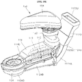
- FIG. 10 is a perspective view illustrating the second connection duct 1123, the second condensing duct 1124, the return duct 114, a fan housing 134, the heater 140, and the distributor 150 according to the embodiment of the present disclosure
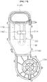
- FIGS. 11 to 13 are a perspective view, a top plan view, and a cross-sectional view illustrating a second downstream duct 1124B, the return duct 114, the fan housing 134, and the heater 140 according to the embodiment of the present disclosure
- FIG. 14 is an exploded perspective view illustrating the second downstream duct 1124B, the return duct 114, the fan housing 134, the heater 140, and the distributor 150 according to the embodiment of the present disclosure
- FIG. 15 is a cross-sectional view illustrating a state in which a fan blade 132 and a motor 136 are installed in the fan housing 134 illustrated in FIG. 13 .
- the second condensing duct 1124 may be disposed lower than the bottom 12B of the tub 12.
- An upstream end 1124U of the second condensing duct 1124 may communicate with the downstream end 1122D of the first condensing duct 1122 ( FIG. 5 and 7 ).
- the condensing duct 112 adjoins the low-temperature air lower than the bottom 12B of the tub 12, such that the moisture vapor contained in the air flowing along the condensing duct 112 is condensed into water and then removed. Therefore, the drying performance may be improved by the simple structure and at low cost.
- the second condensing duct 1124 may include a second upstream duct 1124A and a second downstream duct 1124B sequentially disposed along the flow direction of the air ( FIGS. 7 and 10 ).
- the second upstream duct 1124A and the second downstream duct 1124B may be two duct sections of the second condensing duct 1124.
- the second upstream duct 1124A may communicate with the downstream end 1122D of the first condensing duct 1122 ( FIGS. 5 , 7 , and 10 ).
- the second upstream duct 1124A may be inclined approximately downward along the flow direction of the air.
- the second downstream duct 1124B may communicate with the return duct 114.
- the second downstream duct 1124B may be approximately parallel to the horizontal plane or inclined upward along the flow direction of the air.
- the present disclosure is not limited to this configuration.
- the second condensing duct 1124 may be configured to include only a section parallel to the horizontal plane or inclined upward like the second downstream duct 1124B.
- the second downstream duct 1124B may be the second condensing duct 1124.
- the second condensing duct 1124 may be bent in the vicinity of a downstream end 1124D and extend in an approximately vertical direction (e.g., upward). Therefore, it is possible to prevent the water, which is introduced into the second condensing duct 1124 or produced in the second condensing duct 1124, from being introduced into the return duct 114.
- the horizontal straight distance d1 between the upstream end 1124U and the downstream end 1124D of the second condensing duct 1124 may be longer than a horizontal straight distance d2 between the upstream end 1124U of the second condensing duct 1124 and the outlet port H2 ( FIG. 6 ).
- the downstream end 1124D of the second condensing duct 1124 may be located beyond a midpoint of the bottom 12B of the tub 12 ( FIG. 6 ).
- a horizontal length of the return duct 114 communicating with the outlet port H2 and the downstream end 1124D of the second condensing duct 1124 may increase, and a distance between the downstream end 1124D of the second condensing duct 1124 and the upstream end 114U of the return duct 114 may increase. Therefore, a heater 350 having a sufficiently large size may be disposed inside or outside the return duct 114, and the fan 130 may be disposed between the downstream end 1124D of the second condensing duct 1124 and the upstream end 114U of the return duct 114. Therefore, the drying performance of the dishwasher 1 may be improved by the simple configuration, and the dishwasher 1 may have a compact structure having a small size.
- downstream end 1122D of the first condensing duct 1122 may be positioned in the vicinity of the lower end of the rear portion of one sidewall 12R of the tub 12, and the upstream end 1124U of the second condensing duct 1124 may be positioned in the vicinity of one side end of the rear portion of the bottom 12B of the tub 12 ( FIGS. 3 , 5 , and 7 ).
- the condensing duct 112 may be formed in a shape similar to a straight line, and the length of the condensing duct 112 may decrease. Therefore, the flow resistance may be reduced, and the drying performance may be improved.
- the second condensing duct 1124 may have a second water drain port D2 ( FIG. 13 ). Therefore, the water introduced through the inlet port H1 or the outlet port H2 or the water condensed in the condensing duct 112 may be discharged to the outside through the second water drain port D2, thereby improving the drying performance of the drying device 100.
- a second connection duct 1123 may be disposed between the first condensing duct 1122 and the second condensing duct 1124.
- the second connection duct 1123 may communicate with the downstream end 1122D of the first condensing duct 1122 and the upstream end 1124U of the second condensing duct 1124 ( FIG. 5 and 7 ).
- the condensing duct 112 includes: the first condensing duct 1122 facing the outer surface of one sidewall 12R of the tub 12 and having the upstream end communicating with the inlet port HI; and the second condensing duct 1124 disposed lower than the bottom 12B of the tub 12 and having the upstream end communicating with the downstream end of the first condensing duct 1122. Therefore the condensing duct 112 adjoins the low-temperature air outside of one sidewall 12R of the tub 12 and lower than the bottom 12B of the tub 12 such that the moisture vapor contained in the air flowing along the condensing duct 112 is condensed into water and removed. Therefore, the drying performance may be improved by the simple structure and at low cost.
- the upstream end 114U of the return duct 114 may communicate with the downstream end 1124D of the second condensing duct 1124, and a downstream end 114D of the return duct 114 may communicate with the outlet port H2.
- downstream end 114D of the return duct 114 may communicate with the distributor 150 that is inserted into the washing space 12S through the outlet port H2 and discharges the air into the washing space 12S.
- the second condensing duct 1124 and the return duct 114 may be positioned only under rear portions B11, B12, and B13 of the bottom 12B of the tub 12. Therefore, since the second condensing duct 1124 and the return duct 114 are positioned at the rear side together with the outlet port H2 and the inlet port H1, the second condensing duct 1124 and the return duct 114 may be formed in a shape similar to a straight line, and the lengths of the ducts 1124, and 114 may decrease. Therefore, the flow resistance may be reduced, and the drying performance may be improved.
- the dishwasher 1 may have a compact structure having a small size.
- the return duct 114 may be positioned between the bottom 12B of the tub 12 and the second condensing duct 1124.
- at least a part of the return duct 114 may be disposed under the bottom 12B of the tub 12, and the part of the return duct 114 and the second condensing duct 1124 may be disposed vertically.
- At least a part of the return duct 114 may be disposed higher than the second condensing duct 1124.
- the return duct 114 and the second condensing duct 1124 may at least partially adjoin each other in the longitudinal direction of the return duct 114 and the second condensing duct 1124. At the portion where the return duct 114 and the second condensing duct 1124 adjoin each other, the return duct 114 and the second condensing duct 1124 may be separated by a separation wall W disposed in the longitudinal direction of the return duct 114 and the second condensing duct 1124 ( FIGS. 12 to 15 ).
- the return duct 114 and the second condensing duct 1124 may be easily manufactured by the simple configuration and at low cost.
- the return duct 114 and the second condensing duct 1124 are separated by the single separation wall W, a part of heat generated from the heater 140 disposed in the return duct 114 may be easily transferred to the second condensing duct 1124. Therefore, a small amount of water in the second condensing duct 1124 is vaporized by the heat transferred to the second condensing duct 1124, and thus the humidity in the second condensing duct 1124 decreases, which makes it possible to prevent the proliferation of bacteria or mold in the second condensing duct 1124.
- the return duct 114 may have a third water drain port D3 ( FIG. 13 ). Therefore, the water introduced through the outlet port H2 and the water condensed in the return duct 114 may be discharged to the outside of the return duct 114 through the third water drain port D3, thereby improving the drying performance of the drying device 100.
- the outside of the return duct 114 may be the inside of the second condensing duct 1124 ( FIG. 13 ).
- the fan 130 may be disposed between the downstream end 1124D of the condensing duct 112 and the downstream end 114D of the return duct 114.
- the fan 130 may be disposed between the second condensing duct 1124 and the return duct 114.
- the fan 130 may prevent the occurrence of vortex and allow the air to smoothly flow in a downstream portion (e.g., between the condensing duct and the return duct) of the drying duct 110 where the flow direction of the air is considerably changed. Therefore, flow resistance is not increased, which makes it possible to improve the drying performance of the drying device 100.
- the fan 130 may communicate with the second condensing duct 1124 ( FIG. 15 ). For example, the fan 130 may communicate downwardly with the downstream end 1124D of the second condensing duct 1124.
- the fan 130 may communicate with the return duct 114 ( FIG. 15 ).
- the fan 130 may communicate laterally with the upstream end 114U of the return duct 114.
- the fan 130 may be disposed higher than the downstream end 1124D of the second condensing duct 1124 ( FIG. 15 ).
- the fan 130 may allow the air to flow in the drying duct 110. Specifically, for example, the fan 130 may introduce the air in the first condensing duct 1122 into the second condensing duct 1124. In addition, the fan 130 may introduce the air in the second condensing duct 1124 into the return duct 114. In addition, the fan 130 may discharge the air in the return duct 114 into the washing space 12S through the outlet port H2 and the distributor 150 to be described below.
- the fan 130 may include a fan blade 132, a fan housing 134, and the motor 136.
- the fan blade 132 may be fixedly coupled to a rotary shaft 138 and rotated by the motor 136.
- the fan blade 132 may be accommodated in the fan housing 134.
- the fan housing 134 may communicate with the downstream end 1124D of the second condensing duct 1124 and the upstream end 114U of the return duct 114.
- the fan housing 134 may have a through-hole formed in a lower surface thereof and communicate downwardly with the downstream end 1124D of the second condensing duct 1124 ( FIG. 15 ).
- the fan housing 134 may have a through-hole formed in a lateral surface thereof and communicate laterally with the upstream end 114U of the return duct 114 ( FIG. 15 ).
- the fan housing 134 may include an upper wall 134T.
- the upper wall 134T may be disposed between the fan blade 132 and the motor 136 disposed above the fan blade 132.
- the upper wall 134T may have a hole penetrated by the rotary shaft 138.
- the motor 136 may be coupled to the fan blade 132 by means of the rotary shaft 138.
- the motor 136 may rotate the fan blade 132.
- the motor 136 may be disposed above the fan blade 132. In addition, the motor 136 may be disposed on the upper wall 134T.
- the rotary shaft 138 of the fan 130 may extend in an approximately vertical direction.
- the fan 130 may be installed to be laid between the second condensing duct 1124 and the return duct 114. Therefore, the fan 130 having a sufficiently large size may be installed even though the installation space or the installation position is restricted. Therefore, the drying performance of the dishwasher 1 may be improved by the simple configuration and at low cost, and the dishwasher 1 may have a compact structure having a small size.
- the fan 130 may be a centrifugal fan.
- the motor 136 since the motor 136 may be disposed above the fan blade 132, it is possible to prevent the water from being introduced into the motor 136.
- the heater 140 may be disposed between the downstream end 1124D of the condensing duct 112 and the downstream end 114D of the return duct 114.
- the heater 140 may be disposed in the return duct 114.
- the heater 140 may heat the air in the downstream portion (e.g., the return duct) of the drying duct 110 close to the outlet port H2 and discharge the high-temperature dry air into the washing space 12S, thereby improving the drying performance by the simple configuration and at low cost.
- the downstream portion e.g., the return duct
- the heater 140 may be disposed in the return duct 114 ( FIGS. 10 to 15 ). However, the present disclosure is not limited to this configuration. For example, unlike the drawings, the heater 140 may be provided adjacent to the return duct 114 and disposed outside the return duct 114.
- the heater 140 Since the heater 140 is disposed in the return duct 114 as described above, the air may be effectively heated in the return duct 114 close to the outlet port H2. Therefore, the heated air flowing into the washing space 12S may effectively remove moisture remaining on dishes in the washing space 12S. Therefore, the drying performance may be improved by the simple structure and at low cost.
- the heater 140 is disposed in the return duct 114, the heater 140 is positioned to be distant from the water introduced into the condensing duct 112 or the water condensed in the condensing duct 112 without coming into contact with the water. Therefore, it is possible to prevent the heat generated by the heater 140 from vaporizing a large amount of water collected in the condensing duct 112. Therefore, the high-temperature dry air in the return duct 114 may flow into the washing space 12S, thereby improving the drying performance.
- the heater 140 may heat the air in the drying duct 110.
- the drying device 100 includes the drying duct 110, the fan 130, and the heater 140, and the drying duct 110 is disposed outside the tub 12 and includes the condensing duct 112 and the return duct 114, which makes it possible to improve the drying performance by the simple configuration and at low cost.
- the distributor 150 may include an insertion part 152 and a lid 154.
- a lower end of the insertion part 152 may communicate with the downstream end 114D of the return duct 114, and an upper end of the insertion part 152 may be coupled to the lid 154.
- the insertion part 152 may be installed to penetrate the outlet port H2 formed in the bottom 12B of the tub 12.
- the air heated in the return duct 114 may flow into the washing space 12S through the insertion part 152.
- the lid 154 may be installed at an upper end of the insertion part 152 and disposed in the washing space 12S.
- the lid 154 may prevent the water in the washing space 12S from being introduced into the insertion part 152 and the return duct 114.
- the lid 154 may prevent the air flowing out of the insertion part 152 from flowing upward in the vertical direction when the air is introduced into the washing space 12S. Therefore, since the condition i) is satisfied, the dry air introduced into the washing space 12S through the outlet port H2 may effectively circulate everywhere in the washing space 12S until the dry air is introduced into the drying device 100 through the inlet port H1, thereby improving the drying efficiency.
- the second downstream duct 1124B, the fan housing 134, and the return duct 114 illustrated in FIGS. 11 to 13 may include a first housing C1, a second housing C2, a third housing C3, and a fourth housing C4, as illustrated in FIG. 14 .
- the first housing C1 may be disposed at the lower side and opened upward.
- the second housing C2 may be disposed on the first housing C1 and coupled to the first housing C1.
- the third housing C3 may be opened downward, disposed on the second housing C2, and coupled to the second housing C2.
- the fourth housing C4 may be disposed on one end of the second housing C2 and coupled to the second housing C2.
- the second downstream duct 1124B may be defined by the first housing C1 and the second housing C2, and the return duct 114 may be defined by the second housing C2 and the third housing C3.
- the separation wall W may be the bottom of the second housing C2.
- the fan housing 134 may be defined by one end of the second housing C2 and the fourth housing C4. That is, a part of the fan housing 134 (one end of the second housing) may be integrated with a part of the return duct 114 (the remaining part of the second housing).
- the fourth housing C4 may be the upper wall 134T of the fan housing 134.
- the second water drain port D2 may be formed in the bottom of the first housing C1, and the third water drain port D3 may be formed in the bottom of the second housing C2.
- the heater 140 may be disposed in the internal space defined by coupling the second housing C2 and the third housing C3.
- a fixing part 142 which has high heat resistance and low thermal conductivity, may be fixed to the second housing C2 or the third housing C3, and the heater 140 may be installed by being coupled to the fixing part 142. Therefore, it is possible to prevent the second housing C2 or the third housing C3 from being damaged by the heater 140.
- the second downstream duct 1124B, the fan housing 134, and the return duct 114 may be configured by coupling the first housing C1, the second housing C2, the third housing C3, and the fourth housing C4. Therefore, the drying device 100 may be simply and easily manufactured and easily maintained. Further, the drying device 100 may have a compact structure having a small size.
- the drying duct 110 is divided into the condensing duct 112 and the return duct 114.
- the condensing duct 112 and the return duct 114 may be integrated.
- the first condensing duct 1122 and the second condensing duct 1124 may also be integrated.
- the ducts 110, 112, 1122, 1124, and 114 may each be made of a metallic material such as aluminum or stainless steel.
- the ducts 110, 112, 1122, 1124, and 114 may be manufactured by steel metal working or injection molding.
- drying device 100 may be made of plastic.
- tub 100 drying device 110: drying duct 112: condensing duct 1122: first condensing duct 1122A: first upstream duct 1122B: heat exchange duct 1122C: first downstream duct 1123: second connection duct 1124: second condensing duct 1124A: second upstream duct 1124B: second downstream duct 114: return duct 120: cold air supply module 122: first outside air inflow duct 123: first connection duct 124: second outside air inflow duct 126: heat exchange flow path part 1262: plate 1264: partition wall 128: cooling fan 130: fan 132: fan blade 134: fan housing 136: motor 138: rotary shaft 140: heater 150: distributor
Landscapes
- Washing And Drying Of Tableware (AREA)
- Detail Structures Of Washing Machines And Dryers (AREA)
Abstract
Description
- The present disclosure relates to a dishwasher, and more particularly, to a dishwasher that improves drying performance and prevents backflow of water by a simple configuration and at low cost, has a compact structure with a small size, and improves durability and stability.
- A dishwasher is a household electrical appliance that sprays a washing liquid to washing targets such as dishes or cookware to remove foreign substances remaining on the washing targets.
- The dishwasher generally includes a tub configured to provide a washing space, a rack disposed in the tub and configured to accommodate dishes and the like, a spray arm configured to spray a washing liquid to the rack, a sump configured to store the washing liquid, and a washing pump configured to supply the spray arm with the washing liquid stored in the sump.
- In addition, the dishwasher may have a drying module. The drying module may remove moisture remaining on the dish (a washing target or a drying target) by supplying heated air into the tub (a washing chamber).
- The drying modules may be classified into an open-circulation drying module and a closed-circulation drying module. The open-circulation drying module may discharge moist air from the tub to the outside of the tub, heat outside air, and supply the heated air into the tub. In contrast, the closed-circulation drying module may discharge moist air from the tub to the outside of the tub, remove moisture from the discharged air, and then supply the tub with the air from which the moisture is removed.
- The closed-circulation drying module may have better drying performance than the open-circulation drying module. But the manufacturing cost of the closed-circulation drying module is higher than that of the open-circulation drying module. And the closed-circulation drying module requires a wide installation space, which may obstruct the miniaturization of the dishwasher. Therefore, there is a need for a closed-circulation drying module capable of being simply manufactured at low cost, having a compact structure with a small size, and improving drying performance.
- In addition, the drying module generally has a fan for allowing air to flow. When water is introduced into a motor included in the fan, the fan is broken down and cannot perform the air-drying operation. Therefore, there is a need for a structure to prevent water from coming into contact with the fan.
- In addition, the drying module generally has a heater for heating air. When water is present at the periphery of the heater, the water is vaporized into moisture vapor, and the moisture vapor is introduced into the tub, which may cause a deterioration in drying performance. Therefore, there is a need for a structure to prevent water from being present at the periphery of the heater.
- In addition, the fan or the heater needs to have a large size to effectively move or heat the air to improve the drying performance. Therefore, there is a need for a drying module that has a fan or a heater with a large size while the drying module having a compact structure with a small size.
- The related art will be described below.
-
EP 2757930 A1 relates to a dishwasher having a drying system, in which air in a tub is discharged to the outside through a condensation assembly, and outside air is supplied into the tub through an assembly for blowing and heating drying air. - However, because the related art relates to the open-circulation drying module, the related art does not disclose the closed-circulation drying module.
- In addition, the related art discloses a 'V'-shaped flow tube to prevent water from coming into contact with a motor of the assembly for blowing and heating drying air. The 'V'-shaped flow tube has a long length and requires a large installation space. For this reason, the drying module cannot be miniaturized.
- In addition, when the length of the 'V'-shaped flow tube is decreased to miniaturize the dishwasher, a size of a heater disposed in the 'V'-shaped flow tube decreases, and thus an air heating area decreases, which may cause a deterioration in drying performance.
- In addition, water is collected in an elbow portion of the 'V'-shaped flow tube. Because the heater (heating means) is disposed at the periphery of the elbow portion, the water may be vaporized into moisture vapor by the heater, and the moisture vapor may be introduced into the tub. For this reason, the drying performance may deteriorate.
- An object of the present disclosure is to provide a dishwasher capable of improving drying performance by a simple configuration and at low cost.
- Another object of the present disclosure is to provide a dishwasher capable of preventing water from flowing reversely.
- Still another object of the present disclosure is to provide a dishwasher having a compact structure with a small size.
- Yet another object of the present disclosure is to provide a dishwasher capable of preventing proliferation of bacteria or mold in a duct.
- Still yet another object of the present disclosure is to provide a dishwasher having improved durability and stability.
- A further object of the present disclosure is to provide a dishwasher having excellent drying performance in spite of being provided with various components such as a washing pump and a sump lower than the bottom of a tub to greatly limit the installation space of the drying device.
- The objects of the present disclosure are not limited to the above-mentioned objects, and other objects and advantages of the present disclosure, which are not mentioned above, may be understood from the following descriptions and more clearly understood from the embodiment of the present disclosure. In addition, it can be easily understood that the objects and advantages of the present disclosure may be realized by means defined in the claims and a combination thereof.
- The invention is specified by the independent claim. Preferred embodiments are defined in the dependent claims.
- To achieve the objects, the present disclosure provides a dishwasher including a
tub 12, adoor 14, and adrying device 100. - The
tub 12 includes abottom 12B, anupper wall 12T, onesidewall 12R, theother sidewall 12L, and a rear wall 12RR - A
washing space 12S is formed in thetub 12. - The
door 14 is disposed at a front side of thetub 12. - The
door 14 is configured to open or close thewashing space 12S. - The
drying device 100 is configured to dry thewashing space 12S. - The bottom and the upper wall face each other in a vertical direction.
- The rear wall and the door face each other in a first direction.
- One sidewall and the other sidewall face each other in a second direction.
- An inlet port is formed in a rear upper portion of one sidewall of the tub.
- An outlet port is formed in one rear side portion of the bottom of the tub.
- The
drying device 100 includes adrying duct 110, afan 130, and aheater 140. - The
drying duct 110 is configured to communicates with the inlet port H1 and the outlet port H2. - The
drying duct 110 is disposed outside thetub 12. - The
drying duct 110 includes acondensing duct 112 and areturn duct 114. - The
fan 130 is configured to allow the air in thedrying duct 110 to flow. - The
heater 140 is configured to heat the air in thedrying duct 110. - The
condensing duct 112 includes afirst condensing duct 1122 and asecond condensing duct 1124. - The
first condensing duct 1122 faces an outer surface of the onesidewall 12R. - The
first condensing duct 1122 has anupstream end 1122U adapted to communicate with the inlet port H1. - The
second condensing duct 1124 is disposed lower than thebottom 12B. - The
second condensing duct 1124 has anupstream end 1124U adapted to communicate with adownstream end 1122D of thefirst condensing duct 1122. - The
return duct 114 has anupstream end 114U communicating with adownstream end 1124D of thesecond condensing duct 1124, and adownstream end 114D communicating with the outlet port H2. - In the embodiment, the outlet port H2 may meet an imaginary vertical surface S that passes through the inlet port H1 and extends in the second direction and the vertical direction.
- In the embodiment, the second
condensing duct 1124 may be bent in the vicinity of a downstream end thereof and extend in the vertical direction. - In the embodiment, the horizontal straight distance d1 between the upstream end and the downstream end of the
second condensing duct 1124 may be longer than a horizontal straight distance d2 between the upstream end of thesecond condensing duct 1124 and the outlet port H2. - In the embodiment, the
second condensing duct 1124 and thereturn duct 114 may be positioned only under rear portion of the bottom 12B of thetub 12. - In the embodiment, the
return duct 114 may be positioned between the bottom 12B of thetub 12 and thesecond condensing duct 1124. - In the embodiment, the
return duct 114 and thesecond condensing duct 1124 may at least partially adjoin each other in the longitudinal direction of thereturn duct 114 and thesecond condensing duct 1124. - The
return duct 114 and thesecond condensing duct 1124 may be separated by a separation wall W disposed in the longitudinal direction at the portion where thereturn duct 114 and thesecond condensing duct 1124 adjoin each other. - In the embodiment, the
fan 130 and theheater 140 may be disposed between a downstream end of the condensingduct 112 and a downstream end of thereturn duct 114. - In the embodiment, the
heater 140 may be disposed in thereturn duct 114. - In the embodiment, the
fan 130 may be disposed higher than the downstream end of thesecond condensing duct 1124 and communicate with thereturn duct 114. - In the embodiment, the
fan 130 may include afan blade 132, afan housing 134, and amotor 136. - The
fan housing 134 may accommodate thefan blade 132. - The
motor 136 may rotate thefan blade 132. - The
motor 136 may be disposed above thefan blade 132. - The
fan housing 134 may include anupper wall 134T disposed between thefan blade 132 and themotor 136. - The
fan housing 134 may communicate with a downstream end of thesecond condensing duct 1124 and an upstream end of thereturn duct 114. - In the embodiment, a
rotary shaft 138 of thefan 130 may extend in the vertical direction. - In the embodiment, the
downstream end 1122D of thefirst condensing duct 1122 may be positioned in the vicinity of a lower end of a rear portion of the onesidewall 12R. - The
upstream end 1124U of thesecond condensing duct 1124 may be positioned in the vicinity of one side end of a rear portion of the bottom 12B. - In the embodiment, the dishwasher may further include a cold
air supply module 120. - The cold
air supply module 120 may be disposed outside thetub 12. - The cold
air supply module 120 may at least partially adjoin thefirst condensing duct 1122. - In the embodiment, the cold
air supply module 120 may include a first outsideair inflow duct 122, a second outsideair inflow duct 124, and a heat exchangeflow path part 126. - The first outside
air inflow duct 122 may be disposed lower than the bottom 12B. - Outside air may be introduced into the first outside
air inflow duct 122 through the upstream end of first outsideair inflow duct 122. - The second outside
air inflow duct 124 may face or adjoin an outer surface of the onesidewall 12R. - The second outside
air inflow duct 124 may have an upstream end communicating with a downstream end of the first outsideair inflow duct 122. - The heat exchange
flow path part 126 may adjoin thefirst condensing duct 1122. - The heat exchange
flow path part 126 may have an upstream end communicating with a downstream end of the second outsideair inflow duct 124. - In the embodiment, a cooling
fan 128 configured to suck outside air may be disposed at the periphery of the upstream end of the first outsideair inflow duct 122 or in the first outsideair inflow duct 122. - In the embodiment, the heat exchange
flow path part 126 may extend along an outer circumferential surface of thefirst condensing duct 1122. - The
downstream end 126D of the heat exchangeflow path part 126 may be positioned in parallel in the second direction with theend 1122E in a width direction of thefirst condensing duct 1122. - The air may be discharged to the outside through the downstream end of the heat exchange
flow path part 126. - According to the embodiment of the present disclosure, the
drying device 100 includes the dryingduct 110, thefan 130, and theheater 140. The dryingduct 110 is disposed outside thetub 12 and includes the condensingduct 112 and thereturn duct 114. Therefore, because the condensingduct 112 adjoins low-temperature outside air outside thetub 12, moisture vapor contained in the air flowing along the condensingduct 112 is condensed into water and then removed. Therefore, the drying performance may be improved by the simple structure and at low cost. - According to the embodiment of the present disclosure, the condensing
duct 112 includes: thefirst condensing duct 1122 facing the outer surface of onesidewall 12R and having the upstream end communicating with the inlet port HI; and thesecond condensing duct 1124 disposed lower than the bottom 12B and having the upstream end communicating with the downstream end of thefirst condensing duct 1122. Therefore, the condensingduct 112 adjoins the low-temperature air outside of oneside wall 12R and lower than the bottom 12B of thetub 12, such that the moisture vapor contained in the air flowing along the condensingduct 112 is condensed into water and then removed. Therefore, the drying performance may be improved by the simple structure and at low cost. - According to the embodiment of the present disclosure, the inlet port H1 through which the air in the
washing space 12S is introduced into the dryingduct 110 may be formed in the rear upper portion R11 of onesidewall 12R of thetub 12. In addition, the outlet port H2 through which the air in the dryingduct 110 is discharged to thewashing space 12S may be formed in one rear side portion B11 of the bottom 12B of thetub 12. - Therefore, since both the outlet port H2 and the inlet port H1 are formed in one rear side of the
tub 12, a horizontal distance between the outlet port H2 and the inlet port H1 may decrease. In addition, since the outlet port H2 is formed in the bottom 12B and the inlet port H1 is formed in the upper portion of onesidewall 12R, a vertical distance between the outlet port H2 and the inlet port H1 may increase. Therefore, the dry air introduced into thewashing space 12S through the outlet port H2 may effectively circulate everywhere in thewashing space 12S until the dry air is introduced into thedrying device 100 through the inlet port H1, thereby improving the drying efficiency. - In addition, since both the outlet port H2 and the inlet port H1 are formed at the rear side of the
tub 12, the dryingduct 110 may be disposed at the periphery of the rear side of thetub 12, and a coldair supply module 120 may be disposed at the periphery of the front side of thetub 12. The periphery of the rear side of thetub 12 may be blocked approximately by the wall, and the periphery of the front side of the tub 12 (particularly, the front lower portion of the tub) is opened forward, such that a temperature of the air at the periphery of the front side of thetub 12 may be lower. Therefore, the coldair supply module 120 may effectively reduce humidity of the air in the dryingduct 110 by using the cold air at the periphery of the front side of thetub 12, thereby improving the drying performance. - In addition, since the outlet port H2 is formed at the rear side of the
tub 12, thedistributor 150 of thedrying device 100 may be disposed at the rear side of thetub 12. Therefore, when thedoor 14 disposed at the front side of thetub 12 is opened, thedistributor 150 of thedrying device 100 does not obstruct a visual field. Therefore, it is possible to improve the aesthetic appearance and easily manage various types of devices in thetub 12 without being hindered by thedistributor 150 of thedrying device 100. - According to the embodiment of the present disclosure, the outlet port H2 may meet an imaginary vertical surface S that passes through the inlet port H1 and extends in the second direction and the vertical direction. Therefore, the horizontal distance between the outlet port H2 formed in the bottom 12B of the
tub 12 and the inlet port H1 formed in onesidewall 12R of thetub 12 is minimized. Therefore, the dry air introduced into thewashing space 12S through the outlet port H2 may effectively circulate everywhere in thewashing space 12S until the dry air is introduced into thedrying device 100 through the inlet port H1. Therefore, the drying efficiency may be further improved. - According to the embodiment of the present disclosure, the
second condensing duct 1124 may be bent in the vicinity of adownstream end 1124D and extend in the vertical direction (e.g., upward). Therefore, it is possible to prevent the water, which is introduced into thesecond condensing duct 1124 or produced in thesecond condensing duct 1124, from being introduced into thereturn duct 114. - According to the embodiment of the present disclosure, the horizontal straight distance d1 between the
upstream end 1124U and thedownstream end 1124D of thesecond condensing duct 1124 may be longer than a horizontal straight distance d2 between theupstream end 1124U of thesecond condensing duct 1124 and the outlet port H2. Therefore, even though the outlet port H2 is formed in the vicinity of the inlet port H1 in the horizontal direction to improve the drying performance, a horizontal length of thereturn duct 114 communicating with the outlet port H2 and thedownstream end 1124D of thesecond condensing duct 1124 may increase, and a distance between thedownstream end 1124D of thesecond condensing duct 1124 and theupstream end 114U of thereturn duct 114 may increase. Therefore, a heater 350 having a sufficiently large size may be disposed inside or outside thereturn duct 114, and thefan 130 may be disposed between theupstream end 114U of thereturn duct 114 and thedownstream end 1124D of thesecond condensing duct 1124. Therefore, the drying performance of thedishwasher 1 may be improved by the simple configuration, and thedishwasher 1 may have a compact structure having a small size. - According to the embodiment of the present disclosure, the
second condensing duct 1124 and thereturn duct 114 may be positioned only under rear portions B11, B12, and B13 of the bottom 12B of thetub 12. Therefore, since thesecond condensing duct 1124 and thereturn duct 114 are positioned at the rear side together with the outlet port H2 and the inlet port H1, thesecond condensing duct 1124 and thereturn duct 114 may be formed in a shape similar to a straight line, and the lengths of theducts dishwasher 1 may have a compact structure having a small size. - According to the embodiment of the present disclosure, the
return duct 114 may be positioned between the bottom 12B of thetub 12 and thesecond condensing duct 1124. Therefore, it is possible to prevent the water introduced into thesecond condensing duct 1124 through the inlet port H1 and the water condensed in the condensingduct 112 from being introduced into thereturn duct 114. Therefore, it is possible to prevent the water in the condensingduct 112 from being introduced into thewashing space 12S through the outlet port H2 communicating with thereturn duct 114, thereby improving the drying performance. - According to the embodiment of the present disclosure, the
return duct 114 and thesecond condensing duct 1124 may at least partially adjoin each other in the longitudinal direction of thereturn duct 114 and thesecond condensing duct 1124. At the portion where thereturn duct 114 and thesecond condensing duct 1124 adjoin each other, thereturn duct 114 and thesecond condensing duct 1124 may be separated by a separation wall W disposed in the longitudinal direction of thereturn duct 114 and thesecond condensing duct 1124. Therefore, thereturn duct 114 and thesecond condensing duct 1124 may be easily manufactured by the simple configuration and at low cost. In addition, since thereturn duct 114 and thesecond condensing duct 1124 are separated by the single separation wall W, a part of heat generated from theheater 140 disposed in thereturn duct 114 may be easily transferred to thesecond condensing duct 1124. Therefore, a small amount of water in thesecond condensing duct 1124 is vaporized by the heat transferred to thesecond condensing duct 1124, and thus the humidity in thesecond condensing duct 1124 decreases, which makes it possible to prevent the proliferation of bacteria or mold in thesecond condensing duct 1124. - According to the embodiment of the present disclosure, the
fan 130 and theheater 140 is disposed between the downstream end of the condensingduct 112 and the downstream end of thereturn duct 114. Therefore, thefan 130 may allow the air to smoothly flow in the downstream portion (e.g., between the condensing duct and the return duct) of the dryingduct 110 where the flow direction of the air is considerably changed, thereby reducing the flow resistance. Further, theheater 140 may heat the air in the downstream portion (e.g., the return duct) of the dryingduct 110 close to the outlet port H2 and discharge the high-temperature dry air into thewashing space 12S. As a result, it is possible to improve the drying performance by the simple configuration and at low cost. - According to the embodiment of the present disclosure, the
heater 140 may be disposed in thereturn duct 114. Therefore, since the high-temperature air, which is heated in thereturn duct 114 close to the outlet port H2, flows into thewashing space 12S, the heated air flowing into thewashing space 12S may effectively remove moisture remaining on dishes in thewashing space 12S. Therefore, the drying performance may be improved by the simple structure and at low cost. In addition, since theheater 140 does not come into contact with the water introduced into the condensingduct 112 or the water condensed in the condensingduct 112, it is possible to prevent the heat generated by theheater 140 from vaporizing a large amount of water collected in the condensingduct 112. Therefore, the high-temperature dry air in thereturn duct 114 may flow into thewashing space 12S, thereby improving the drying performance. - According to the embodiment of the present disclosure, the
fan 130 may be disposed higher than thedownstream end 1124D of thesecond condensing duct 1124. Therefore, it is possible to prevent amotor 136 of thefan 130 from coming into contact with the water introduced into the condensingduct 112 or the water condensed in the condensingduct 112. Therefore, it is possible to prevent the water from being introduced into themotor 136 of thefan 130 and thus prevent thefan 130 from being broken down, thereby improving the durability and stability of thedrying device 100. - According to the embodiment of the present disclosure, the
motor 136 may be disposed above thefan blade 132, and thefan housing 134 may include theupper wall 134T disposed between thefan blade 132 and themotor 136. Therefore, even though thefan blade 132 comes into contact with the water introduced into thereturn duct 114 through the outlet port H2, the water being in contact with thefan blade 132 is blocked by theupper wall 134T, such that the water cannot come into contact with themotor 136. Therefore, it is possible to prevent the water from being introduced into themotor 136 and thus prevent thefan 130 from being broken down, thereby improving the durability and stability of thedrying device 100. - According to the embodiment of the present disclosure, the
rotary shaft 138 of thefan 130 may extend in the vertical direction. Therefore, thefan 130 may be installed to be laid between thesecond condensing duct 1124 and thereturn duct 114. Therefore, thefan 130 having a sufficiently large size may be installed even though the installation space or the installation position is restricted. Therefore, the drying performance of thedishwasher 1 may be improved by the simple configuration and at low cost, and thedishwasher 1 may have a compact structure having a small size. In addition, since themotor 136 may be disposed above thefan blade 132, it is possible to prevent the water from being introduced into themotor 136. - According to the embodiment of the present disclosure, the
downstream end 1122D of thefirst condensing duct 1122 may be positioned in the vicinity of the lower end of the rear portion of onesidewall 12R, and theupstream end 1124U of thesecond condensing duct 1124 may be positioned in the vicinity of one side end of the rear portion of the bottom 12B. For example, thedownstream end 1122D of thefirst condensing duct 1122 may be positioned adjacent to the rear lower portion R13 of onesidewall 12R of thetub 12 and theupstream end 1124U of thesecond condensing duct 1124 may be positioned adjacent to the one rear side portion B11 of bottom 12B of thetub 12. For example, thedownstream end 1122D of thefirst condensing duct 1122 may be positioned closest to rear lower portion R13 among the nine regions R11 to R33 of onesidewall 12R of the tub 12 (Fig 2 or3 ), thereby being positioned in the vicinity of the lower end of the rear portion of onesidewall 12R. And theupstream end 1124U of thesecond condensing duct 1124 may be positioned closest to one rear side portion B11 among the nine regions B11 to B33 of bottom 12B of the tub 12 (Fig 2 or3 ), thereby being positioned in the vicinity of one side end of the rear portion ofbottom 12B. Therefore, since both thedownstream end 1122D of thefirst condensing duct 1122 and theupstream end 1124U of thesecond condensing duct 1124 are positioned at the rear side together with the inlet port H1 and the outlet port H2, the condensingduct 112 may be formed in a shape similar to a straight line, and the length of the condensingduct 112 may decrease. Therefore, the flow resistance may be reduced, and the drying performance may be improved. - According to the exemplary embodiment of the present disclosure, the dishwasher may further include the cold
air supply module 120 disposed outside thetub 12 and configured to at least partially adjoin thefirst condensing duct 1122. Therefore, the coldair supply module 120 may effectively remove moisture vapor, which is contained in the air flowing along thefirst condensing duct 1122, by condensing the moisture vapor into the water. Therefore, the drying performance may be improved by the simple structure and at low cost. - According to the embodiment of the present disclosure, the cold
air supply module 120 includes the first outsideair inflow duct 122 disposed lower than the bottom 12B and configured to allow the outside air to be introduced thereinto, the second outsideair inflow duct 124 configured to face or adjoin the outer surface of onesidewall 12R, and the heat exchangeflow path part 126 configured to adjoin thefirst condensing duct 1122 and communicate with the second outsideair inflow duct 124. Therefore, it is possible to effectively remove moisture vapor, which is contained in the air flowing along thefirst condensing duct 1122, by condensing the moisture vapor into the water with the cold air lower than thetub 12. Therefore, the drying performance may be improved by the simple structure and at low cost. - According to the embodiment of the present disclosure, the cooling
fan 128 may be disposed in the first outsideair inflow duct 122 or at the periphery of theupstream end 122U of the first outsideair inflow duct 122. Therefore, since the coolingfan 128 may be disposed lower than thetub 12, the coolingfan 128 may suck the cold air lower than thetub 12 and supply the cold air to the heat exchangeflow path part 126, thereby improving the cooling efficiency. In addition, because the space lower than thetub 12 is comparatively large, it is possible to improve the cooling efficiency by increasing the size of the coolingfan 128. - According to the embodiment of the present disclosure, the heat exchange
flow path part 126 may extend along the outer circumferential surface of thefirst condensing duct 1122, and thedownstream end 126D of the heat exchangeflow path part 126 may be positioned in parallel in the second direction with theend 1122E in the width direction of thefirst condensing duct 1122. The air may be discharged to the outside through thedownstream end 126D of the heat exchangeflow path part 126. Therefore, the heat exchangeflow path part 126 may be configured and the installation space of the heat exchangeflow path part 126 may be minimized by the simple configuration and at low cost. In addition, a length of the heat exchangeflow path part 126 is decreased, and the flow resistance is reduced, such that the cooling performance may be improved. - The specific effects of the present disclosure, together with the above-mentioned effects, will be described along with the description of specific items for carrying out the present disclosure.
-
-
FIG. 1 is a cross-sectional view of a dishwasher according to an embodiment of the present disclosure. -
FIG. 2 is a perspective view of a tub according to the embodiment of the present disclosure,FIGS. 3 to 6 are a perspective view, a front view, a side view, and a top plan view illustrating the drying device and the tub according to the embodiment of the present disclosure, andFIG. 7 is a perspective view of a drying device according to the embodiment of the present disclosure. -
FIG. 8 is a view illustrating a structure in which some components of the drying device illustrated inFIGS. 3 to 7 are integrally manufactured, andFIG. 9 is a perspective view illustrating a heat exchange duct and a heat exchange flow path part disposed between a first upstream duct and a first downstream duct in the structure illustrated inFIG. 8 . -
FIG. 10 is a perspective view illustrating the a second connection duct, the second condensing duct, the return duct, a fan housing, the heater, and the distributor according to the embodiment of the present disclosure, andFIGS. 11 to 13 are a perspective view, a top plan view, and a cross-sectional view illustrating a second downstream duct, the return duct, the fan housing, and the heater according to the embodiment of the present disclosure. -
FIG. 14 is an exploded perspective view illustrating the second downstream duct, the return duct, the fan housing, the heater, and the distributor according to the embodiment of the present disclosure. -
FIG. 15 is a cross-sectional view illustrating a state in which a fan blade and a motor are installed in the fan housing illustrated inFIG. 13 . - The above-mentioned objects, features, and advantages will be described in detail below with reference to the accompanying drawings, and thus the technical scope of the present disclosure will be easily carried out by those skilled in the art to which the present disclosure pertains. In the description of the present disclosure, the specific descriptions of publicly known technologies related with the present disclosure will be omitted when it is determined that the specific descriptions may unnecessarily obscure the subject matter of the present disclosure. Hereinafter, exemplary embodiments of the present disclosure will be described in detail with reference to the accompanying drawings. In the drawings, the same reference numerals are used to indicate the same or similar constituent elements.
- The present disclosure is not limited to the embodiments disclosed herein, but will be variously changed and implemented in various different forms. The embodiments are provided so that the present disclosure will be thorough and complete, and also to provide a more complete understanding of the scope of the present disclosure to those of ordinary skill in the art. Therefore, it should be understood that the present disclosure is not limited to the embodiments disclosed below, but the configuration of any one embodiment and the configuration of another embodiment can be substituted or added, and the present disclosure includes all alterations, equivalents, and alternatives that are included in the technical scope of the present disclosure as defined by the appended claims.
- It should be interpreted that the accompanying drawings are provided only to allow those skilled in the art to easily understand the exemplary embodiments disclosed in the present specification, and the technical scope disclosed in the present specification is not limited by the accompanying drawings, and includes all alterations, equivalents, and alternatives that are included in the technical scope of the present disclosure. In the drawings, sizes or thicknesses of constituent elements may be exaggerated, increased, or decreased for convenience of understanding, but the protection scope of the present disclosure should not be restrictively construed.
- The terms used in the present specification are used only for the purpose of describing particular examples or embodiments and are not intended to limit the present disclosure. Further, singular expressions include plural expressions unless clearly described as different meanings in the context. In the present application, the terms "comprises," "comprising," "includes," "including," "containing," "has," "having", and other variations thereof are inclusive and therefore specify the presence of features, integers, steps, operations, elements, components, and/or combinations thereof disclosed in the specification. That is, in the present application, the terms "comprises," "comprising," "includes," "including," "containing," "has," "having", and other variations thereof do not preclude the presence or addition of one or more other features, integers, steps, operations, elements, components, and/or combinations thereof. It should not be interpreted that in the present application, the terms "comprises," "comprising," "includes," "including," "containing," "has," "having", and other variations thereof necessarily include features, integers, steps, operations, elements, components, and/or combinations thereof disclosed in the specification.
- The terms including ordinal numbers such as 'first', 'second', and the like may be used to describe various constituent elements, but the constituent elements are not limited by the terms. These terms are used only to distinguish one constituent element from another constituent element. Unless explicitly described to the contrary, the first constituent element may, of course, be the second constituent element.
- When one constituent element is described as being "coupled" or "connected" to another constituent element, it should be understood that one constituent element can be coupled or connected directly to another constituent element, and an intervening constituent element can also be present between the constituent elements. When one constituent element is described as being "coupled directly to" or "connected directly to" another constituent element, it should be understood that no intervening constituent element is present between the constituent elements.
- When one constituent element is described as being "disposed/positioned higher than" or "disposed/positioned lower than" another constituent element, it should be understood that one constituent element can be disposed/positioned directly on or beneath another constituent element, and a space or an intervening constituent element can also be present between the constituent elements.
- Unless otherwise defined, all terms used herein, including technical or scientific terms, have the same meaning as commonly understood by those skilled in the art to which the present disclosure pertains. The terms such as those defined in a commonly used dictionary should be interpreted as having meanings consistent with meanings in the context of related technologies and should not be interpreted as ideal or excessively formal meanings unless explicitly defined in the present application.
- For the convenience of description, a direction toward a front surface or a rear surface of a door of a dishwasher in a state in which the door is closed is defined as a first direction or a forward/rearward direction.
- A second direction or a leftward/rightward direction may mean a direction toward left and right sides in the drawings illustrating a front surface of the door in the closed state.
- Hereinafter, a dishwasher according to several embodiments of the present disclosure will be described.
-
FIG. 1 is a cross-sectional view of a dishwasher according to an embodiment of the present disclosure. - Referring to
FIG. 1 , thedishwasher 1 according to the embodiment may include acabinet 11, thetub 12, a plurality ofspray arms sump 50, afilter 70, awashing pump 80, a switchingvalve 85, awater supply valve 32, awater drain pump 35, and adrying device 100. The respective components will be described. - The
cabinet 11 may define an external appearance of thedishwasher 1. - The
tub 12 may be disposed in thecabinet 11. Thetub 12 may have a hexahedral shape opened at a front side thereof. However, the shape of thetub 12 is not limited thereto, and thetub 12 may have various shapes. - A
washing space 12S may be formed in thetub 12 and accommodate a washing target. A door 14 (FIG. 2 ) for opening or closing thewashing space 12S may be provided at a front side of thetub 12. - An inlet port H1 and an outlet port H2, which communicate with the
drying device 100, may be formed in thesidewall 12R and a bottom 12B of thetub 12. In this regard, this configuration will be described. In addition, the bottom 12B of thetub 12 has a communication hole H3 through which a washing liquid is introduced into thesump 50. - The door 14 (
FIG. 2 ) may be disposed at the front side of thetub 12 and open or close thewashing space 12S. - A plurality of
racks washing space 12S. The plurality ofracks lower rack 26 disposed at a lower side of thewashing space 12S, and anupper rack 27 disposed at an upper side of thewashing space 12S. Thelower rack 26 and theupper rack 27 may be disposed to be spaced apart from each other vertically and withdrawn toward a location in front of thetub 12 by sliding. - The plurality of
spray arms spray arms low spray arm 23, anupper spray arm 24, and atop spray arm 25. Thelow spray arm 23 may spray the washing liquid upward toward thelower rack 26. Theupper spray arm 24 may be disposed above thelow spray arm 23 and spray the washing liquid upward toward theupper rack 27. Thetop spray arm 25 may be disposed at an uppermost end of thewashing space 12S and spray the washing liquid downward. - The plurality of
spray arms washing pump 80 through the plurality of spray arm connectingflow tubes - The
sump 50 may be provided lower than the bottom 12B of thetub 12 and collect and store the washing liquid. Specifically, thesump 50 may be connected to a watersupply flow path 33 and supplied with the clean washing liquid including no foreign substances through the watersupply flow path 33, and thesump 50 may store the clean washing liquid. In addition, thesump 50 may be supplied with and store the washing liquid from which foreign substances are removed by thefilter 70. - The
filter 70 may be disposed in thesump 50 and installed in the communication hole H3. Thefilter 70 may filter out foreign substances from the washing liquid containing foreign substances and moving from thetub 12 to thesump 50. - The
water supply valve 32 may control the washing liquid supplied from a water source through the watersupply flow path 33. When thewater supply valve 32 is opened, the washing liquid supplied from the external water source may be introduced into thesump 50 through the watersupply flow path 33. - A water
drain flow path 34 may be connected to thewater drain pump 35 and thesump 50. - The
water drain pump 35 may be connected to the waterdrain flow path 34 and include a water drain motor (not illustrated). - When the
water drain pump 35 operates, the foreign substances filtered out by thefilter 50 and/or the washing liquid may be discharged to the outside through the waterdrain flow path 34. - The
washing pump 80 may be disposed below the bottom 12B of thetub 12 and supply the plurality ofspray arms sump 50. - The switching
valve 85 may selectively connect at least one of the plurality ofspray arms washing pump 80. - The
drying device 100 may be disposed beside onesidewall 12R and lower than the bottom 12B of thetub 12. Thedrying device 100 may communicate with the inside of thewashing space 12S through the inlet port H1 and the outlet port H2. Thedrying device 100 may dry thewashing space 12S in thetub 12. - In a drying step of the
dishwasher 1, the moist air in thewashing space 12S may be introduced into thedrying device 100 through the inlet port H1, and the air dried by thedrying device 100 may be introduced into thewashing space 12S through the outlet port H2. The circulation of the air may be repeatedly performed. Thedrying device 100 may improve drying performance through the closed circulation of the air. - Meanwhile, a space capable of installing the
drying device 100 may be narrow because various components, such as thewashing pump 80, which constitute thedishwasher 1, are installed below the bottom 12B of thetub 12 and thesump 50 is provided lower than the bottom 12B of thetub 12. Therefore, thedrying device 100 needs to have a compact structure having a small size so that thedrying device 100 may be installed in thedishwasher 1. - A
distributor 150 of thedrying device 100 may be inserted into thewashing space 12S through the outlet port H2. Thedistributor 150 may be disposed at an edge corner of thetub 12 so as not to collide with the rotatingspray arm 23. -
FIG. 2 is a perspective view of the tub according to the embodiment of the present disclosure,FIGS. 3 to 6 are a perspective view, a front view, a side view, and a top plan view illustrating the drying device and the tub according to the embodiment of the present disclosure, andFIG. 7 is a perspective view of the drying device according to the embodiment of the present disclosure. - Referring to
FIG. 2 , thetub 12 according to the embodiment may include the bottom 12B, anupper wall 12T, onesidewall 12R, theother sidewall 12L, and the rear wall 12RR. Thewashing space 12S may be defined in thetub 12 by the bottom 12B, theupper wall 12T, onesidewall 12R, theother sidewall 12L, and the rear wall 12RR. For example, onesidewall 12R may be a right sidewall of thetub 12, and theother sidewall 12L may be a left sidewall of thetub 12. - The
door 14 for opening or closing thewashing space 12S may be disposed at the front side of thetub 12. - The bottom 12B and the
upper wall 12T may face each other in the vertical direction, the rear wall 12RR and thedoor 14 may face each other in the first direction, and onesidewall 12R and theother sidewall 12L may face each other in the second direction. - One
sidewall 12R of thetub 12 may be divided into rear portions R11, R12, and R13, central portions R21, R22, and R23, and front portions R31, R32, and R33 in the first direction or the forward/rearward direction. A point at which the rear portion and the central portion of onesidewall 12R are separated may be a point of about 1/4 to 1/3 of a width of onesidewall 12R from a rear end to a front side of onesidewall 12R. A point at which the front portion and the central portion of onesidewall 12R are separated may be a point of about 1/4 to 1/3 of the width of onesidewall 12R from a front end to a rear side of onesidewall 12R. - In addition, one
sidewall 12R oftub 12 may be divided into upper portions R11, R21, and R31, central portions R12, R22, and R32, and lower portions R13, R23, and R33 in the vertical direction or an upward/downward direction. A point at which the upper portion and the central portion of onesidewall 12R are separated may be a point of about 1/4 to 1/3 of a height of onesidewall 12R from an upper end to a lower side of onesidewall 12R. A point at which the lower portion and the central portion of onesidewall 12R are separated may be a point of about 1/4 to 1/3 of the height of onesidewall 12R from a lower end to an upper side of onesidewall 12R. - Therefore, one
sidewall 12R of thetub 12 may be divided into nine regions including a rear upper portion R11, a rear central portion R12, a rear lower portion R13, a central upper portion R21, a central portion R22, a central lower portion R23, a front upper portion R31, a front central portion R32, and a front lower portion R33 in the first direction and the vertical direction. - Like one
sidewall 12R, the bottom 12B of thetub 12 may also be divided into nine regions including one rear side portion B11, a rear central portion B12, the other rear side portion B13, one central side portion B21, a central portion B22, the other central side portion B23, one front side portion B31, a front central portion B32, and the other front side portion B33 in the first direction and the second direction. - The inlet port H1 through which the air in the
washing space 12S is introduced into the dryingduct 110 may be formed in the rear upper portion R11 of onesidewall 12R of thetub 12. In addition, the outlet port H2 through which the air in the dryingduct 110 is discharged to thewashing space 12S may be formed in one rear side portion B11 of the bottom 12B of thetub 12. - Therefore, since both the outlet port H2 and the inlet port H1 are formed in one rear side of the
tub 12, a horizontal distance between the outlet port H2 and the inlet port H1 may decrease. In addition, since the outlet port H2 is formed in the bottom 12B and the inlet port H1 is formed in the upper portion of onesidewall 12R, a vertical distance between the outlet port H2 and the inlet port H1 may increase. - In general, to introduce the air into the specific space and allow the introduced air to effectively circulate in the space, i) it is necessary to prevent the air introduced into the inlet port from flowing directly to the outlet port, and ii) it is necessary to decrease the horizontal distance between the air inlet port and the outlet port and increase the vertical distance between the inlet port and the outlet port.
- As described above, since the condition ii) is satisfied, the dry air introduced into the
washing space 12S through the outlet port H2 may effectively circulate everywhere in thewashing space 12S until the dry air is introduced into thedrying device 100 through the inlet port H1, thereby improving the drying efficiency. Meanwhile, the condition i) may be satisfied by thedistributor 150. - In addition, since both the outlet port H2 and the inlet port H1 are formed at the rear side of the
tub 12, the dryingduct 110 may be disposed at the periphery of the rear side of thetub 12, and a coldair supply module 120 may be disposed at the periphery of the front side of thetub 12. The periphery of the rear side of thetub 12 may be blocked approximately by the wall, and the periphery of the front side of the tub 12 (particularly, the front space lower than the tub) is opened forward, such that a temperature of the air at the periphery of the front side of thetub 12 may be lower. Therefore, the coldair supply module 120 may effectively reduce humidity of the air in the dryingduct 110 by using the cold air at the periphery of the front side of thetub 12, thereby improving the drying performance. - In addition, since the outlet port H2 is formed at the rear side of the
tub 12, thedistributor 150 of thedrying device 100 may be disposed at the rear side of thetub 12. Therefore, when thedoor 14 disposed at the front side of thetub 12 is opened, thedistributor 150 of thedrying device 100 does not obstruct a visual field. Therefore, it is possible to improve the aesthetic appearance and easily manage various types of devices in thetub 12 without being hindered by thedistributor 150 of thedrying device 100. - The outlet port H2 may meet an imaginary vertical surface S that passes through the inlet port H1 and extends in the second direction and the vertical direction. For example, a center of the outlet port H2 may meet the imaginary vertical surface S that passes through a center of the inlet port H1 and extends in the second direction. The configuration in which the outlet port H2 meets the vertical surface S will be described below.
- The outlet port H2, which has a minimum value of the horizontal distance from the inlet port H1 among the outlet ports H2 formed in the bottom 12B and spaced apart from one side end of the bottom 12B toward the other side (the other side in the second direction) by a particular distance, is the outlet port H2 that meets the imaginary vertical surface S.
- When the outlet port H2 meets the vertical surface S, the horizontal distance between the outlet port H2 formed in the bottom 12B of the
tub 12 and the inlet port H1 formed in onesidewall 12R of thetub 12 may be minimized, so the condition ii) is partially satisfied. Therefore the dry air introduced into thewashing space 12S through the outlet port H2 may effectively circulate everywhere in thewashing space 12S until the dry air is introduced into thedrying device 100 through the inlet port H1. Therefore, the drying efficiency may be further improved. - Further referring to
FIGS. 3 to 7 , thedrying device 100 according to the embodiment may include the dryingduct 110, the coldair supply module 120, afan 130, aheater 140, and thedistributor 150. However, the coldair supply module 120 and thedistributor 150 may be omitted from thedrying device 100. The respective components will be described. - The drying
duct 110 communicates with the inlet port H1 and the outlet port H2 and is disposed outside thetub 12. The dryingduct 110 may include the condensingduct 112 and areturn duct 114. - Therefore, because the condensing
duct 112 adjoins low-temperature outside air outside thetub 12, moisture vapor contained in the air flowing along the condensingduct 112 is condensed into water and then removed. Therefore, the drying performance may be improved by the simple structure and at low cost. - The condensing
duct 112 may include thefirst condensing duct 1122 and asecond condensing duct 1124. - The
first condensing duct 1122 may be disposed on onesidewall 12R. Specifically, thefirst condensing duct 1122 may face or adjoin the outer surface or the outer circumferential surface of onesidewall 12R. Anupstream end 1122U of thefirst condensing duct 1122 may communicate with the inlet port H1. - Therefore, the condensing
duct 112 adjoins the low-temperature air outside onesidewall 12R thetub 12, such that the moisture vapor contained in the air flowing along the condensingduct 112 is condensed into water and then removed. Therefore, the drying performance may be improved by the simple structure and at low cost. - Specifically, for example, the
first condensing duct 1122 may include a firstupstream duct 1122A, aheat exchange duct 1122B, and a firstdownstream duct 1122C sequentially disposed along the flow direction of the air (FIGS. 5 and7 ). The firstupstream duct 1122A, theheat exchange duct 1122B, and the seconddownstream duct 1122C may be three duct sections of thefirst condensing duct 1122. - The first
upstream duct 1122A may communicate with the inlet port H1, and the air may be introduced into the firstupstream duct 1122A. - The
heat exchange duct 1122B may adjoin the coldair supply module 120. - The first
downstream duct 1122C may communicate with thesecond condensing duct 1124 and discharge the air to thesecond condensing duct 1124. - A first water drain port D1 may be formed in the first
downstream duct 1122C. Therefore, the water introduced through the inlet port H1 or the water condensed in theheat exchange duct 1122B may be discharged to the outside through the first water drain port D1, thereby improving the drying performance of thedrying device 100. - A suction fan (not illustrated) may be provided at the
upstream end 1122U or the periphery of theupstream end 1122U of thefirst condensing duct 1122. The suction fan may be a centrifugal fan. The suction fan may improve the drying performance by allowing the air to smoothly flow. Since the centrifugal fan is provided, a transverse width (i.e. width in the second direction in the drawings) of thefirst condensing duct 1122 may be minimized, thereby miniaturizing thedishwasher 1. - A
downstream end 1122D of thefirst condensing duct 1122 may be positioned in the vicinity of a lower end of the rear portion of onesidewall 12R of thetub 12. In this regard, this configuration will be described. - The cold
air supply module 120 related to thefirst condensing duct 1122 will be described first, and then thesecond condensing duct 1124 will be described. - The cold
air supply module 120 may be disposed outside thetub 12. At least a part of the coldair supply module 120 may adjoin thefirst condensing duct 1122. - Specifically, for example, the cold
air supply module 120 may include a first outsideair inflow duct 122, a second outsideair inflow duct 124, and a heat exchange flow path part 126 (FIGS. 5 and7 ). - The first outside
air inflow duct 122 may be disposed lower than the bottom 12B of thetub 12, and outside air may be introduced through anupstream end 122U. - The second outside
air inflow duct 124 may face or adjoin an outer surface of onesidewall 12R of thetub 12. Anupstream end 124U may communicate with adownstream end 122D of the first outsideair inflow duct 122. - The heat exchange
flow path part 126 may adjoin thefirst condensing duct 1122, and anupstream end 126U of the heat exchangeflow path part 126 may communicate with adownstream end 124D of the second outsideair inflow duct 124. - Specifically, for example, the heat exchange
flow path part 126 may extend along an outer circumferential surface of thefirst condensing duct 1122. Adownstream end 126D of the heat exchangeflow path part 126 may be positioned approximately in parallel in the second direction with anend 1122E in a width direction (the first direction in the drawings) of the first condensing duct 1122 (FIGS. 7 and9 ). The air may be discharged to the outside through thedownstream end 126D of the heat exchangeflow path part 126. - Therefore, the heat exchange
flow path part 126 may be configured and the installation space of the heat exchangeflow path part 126 may be minimized by the simple configuration and at low cost. In addition, a length of the heat exchangeflow path part 126 is decreased, and the flow resistance is reduced, such that the cooling performance may be improved. - The cooling
fan 128 may be disposed in the first outsideair inflow duct 122 or at the periphery of theupstream end 122U of the first outsideair inflow duct 122. The coolingfan 128 may suck the outside air and supply the outside air into the heat exchangeflow path part 126. - Therefore, since the cooling
fan 128 may be disposed lower than thetub 12, the coolingfan 128 may suck the cold air lower than thetub 12 and supply the cold air to the heat exchangeflow path part 126, thereby improving the cooling efficiency. In addition, because the space lower than thetub 12 is comparatively large, it is possible to improve the cooling efficiency by increasing the size of the coolingfan 128. - Meanwhile, a
first connection duct 123 may be disposed between the first outsideair inflow duct 122 and the second outsideair inflow duct 124. Thefirst connection duct 123 may communicate with thedownstream end 122D of the first outsideair inflow duct 122 and theupstream end 124U of the second outside air inflow duct 124 (FIG. 7 ). - As described above, the dishwasher may further include the cold
air supply module 120 disposed outside thetub 12 and configured to at least partially adjoin thefirst condensing duct 1122. Therefore, the coldair supply module 120 may effectively remove moisture vapor, which is contained in the air flowing along thefirst condensing duct 1122, by condensing the moisture vapor into the water. Therefore, the drying performance may be improved by the simple structure and at low cost. - In addition, the cold
air supply module 120 includes the first outsideair inflow duct 122 disposed lower than the bottom 12B of thetub 12 and configured to allow the outside air to be introduced thereinto, the second outsideair inflow duct 124 configured to face or adjoin the outer surface or the outer surface of onesidewall 12R of thetub 12, and the heat exchangeflow path part 126 configured to adjoin thefirst condensing duct 1122 and communicate with the second outsideair inflow duct 124. Therefore, it is possible to effectively remove the moisture vapor contained in the air flowing along the first outsideair inflow duct 122 by condensing the moisture vapor into water using the cold air lower than thetub 12. Therefore, the drying performance may be improved by the simple structure and at low cost. - The heat exchange
flow path part 126 will be described in more detail with reference toFIGS. 8 and9 . -
FIG. 8 is a view illustrating a structure in which some components of the drying device illustrated inFIGS. 3 to 7 are integrally manufactured, andFIG. 9 is a perspective view illustrating a heat exchange duct and a heat exchange flow path part disposed between a first upstream duct and a first downstream duct in the structure illustrated inFIG. 8 . - Referring to
FIG. 8 , the fistupstream duct 1122A, the firstdownstream duct 1122C, and the second outsideair inflow duct 124 may be integrated. A vacant space may be formed between the firstupstream duct 1122A and the firstdownstream duct 1122C. Theheat exchange duct 1122B and the heat exchangeflow path part 126, which will be described with reference toFIG. 9 , may be installed in the vacant space between the firstupstream duct 1122A and the firstdownstream duct 1122C. - Since the first
upstream duct 1122A, the firstdownstream duct 1122C, and the second outsideair inflow duct 124 are integrated as described above, the manufacturing cost of thedrying device 100 may be reduced, and thedrying device 100 may be easily installed and maintained. - Referring to
FIG. 9 , theheat exchange duct 1122B and the heat exchangeflow path part 126 may be installed between the firstupstream duct 1122A and the firstdownstream duct 1122C in the structure illustrated inFIG. 8 . - The
heat exchange duct 1122B may have a flat tubular shape opened at two opposite ends thereof and communicate vertically with the firstupstream duct 1122A and the firstdownstream duct 1122C illustrated inFIG. 8 . - The heat exchange
flow path part 126 may include aplate 1262 and apartition wall 1264. - The
plate 1262 may be disposed to face at least one of one surface and the other surface in the second direction of theheat exchange duct 1122B. - The
partition wall 1264 may be provided in plural, and the plurality ofpartition walls 1264 may be disposed in parallel between theplate 1262 and one surface or the other surface in the second direction of theheat exchange duct 1122B. - The
plate 1262 and the plurality ofpartition walls 1264 may extend along the outer circumferential surface of theheat exchange duct 1122B in the width direction (the first direction in the drawings) of theheat exchange duct 1122B that intersects the flow direction of the air flowing in theheat exchange duct 1122B. - When the
heat exchange duct 1122B and the heat exchangeflow path part 126 illustrated inFIG. 9 are installed in the vacant space between the firstupstream duct 1122A and the firstdownstream duct 1122C of the structure illustrated inFIG. 8 , thedownstream end 124D of the second outsideair inflow duct 124 may adjoin a lateral end in the first direction of theheat exchange duct 1122B and theplate 1262. Therefore, the cold air introduced into the second outsideair inflow duct 124 may flow to the vacant space between theplate 1262 and theheat exchange duct 1122B. In this case, a plurality of flow paths may be formed between theplate 1262 and theheat exchange duct 1122B by the plurality ofpartition walls 1264 extending in the width direction (the first direction in the drawings) of theheat exchange duct 1122B. - That is, the cold air introduced into the second outside
air inflow duct 124 may flow along the plurality of flow paths formed by theheat exchange duct 1122B, theplate 1262, and the plurality ofpartition walls 1264. The direction in which the cold air flows along the plurality of flow paths formed by the heat exchangeflow path part 126 may intersect the direction in which the moist air flows along theheat exchange duct 1122B. - In this case, as described above, the
downstream end 126D of the heat exchangeflow path part 126 may be positioned approximately in parallel in the second direction with theend 1122E in the width direction (the first direction in the drawings) of the first condensing duct 1122 (FIG. 9 ). - As described above, the heat exchange
flow path part 126 includes theplate 1262 disposed to face at least one of one surface and the other surface in the second direction of theheat exchange duct 1122B, and the plurality ofpartition walls 1264 disposed in parallel between theplate 1262 and one surface or the other surface in the second direction of theheat exchange duct 1122B. Therefore, heat exchangeflow path part 126 may be configured by the simple configuration and at low cost. In addition, since the cold air flows along the outer circumferential surface of theheat exchange duct 1122B, the heat exchange efficiency may be improved. In addition, since the cold air flows along the plurality of flow paths separated from one another, the heat exchange is uniformly performed in a wide area, such that the heat exchange efficiency may be improved. - Meanwhile, as illustrated in
FIG. 9 , since theheat exchange duct 1122B and the heat exchangeflow path part 126 are manufactured separately and then installed between the firstupstream duct 1122A and the firstdownstream duct 1122C of the structure illustrated inFIG. 8 , thedrying device 100 may be easily manufactured, replaced, and repaired. Therefore, the manufacturing cost may be reduced, and the maintenance may be easily performed. -
FIG. 10 is a perspective view illustrating thesecond connection duct 1123, thesecond condensing duct 1124, thereturn duct 114, afan housing 134, theheater 140, and thedistributor 150 according to the embodiment of the present disclosure, andFIGS. 11 to 13 are a perspective view, a top plan view, and a cross-sectional view illustrating a seconddownstream duct 1124B, thereturn duct 114, thefan housing 134, and theheater 140 according to the embodiment of the present disclosure.FIG. 14 is an exploded perspective view illustrating the seconddownstream duct 1124B, thereturn duct 114, thefan housing 134, theheater 140, and thedistributor 150 according to the embodiment of the present disclosure.FIG. 15 is a cross-sectional view illustrating a state in which afan blade 132 and amotor 136 are installed in thefan housing 134 illustrated inFIG. 13 . - Further referring to
FIGS. 10 to 15 , thesecond condensing duct 1124 may be disposed lower than the bottom 12B of thetub 12. Anupstream end 1124U of thesecond condensing duct 1124 may communicate with thedownstream end 1122D of the first condensing duct 1122 (FIG. 5 and7 ). - Therefore, the condensing
duct 112 adjoins the low-temperature air lower than the bottom 12B of thetub 12, such that the moisture vapor contained in the air flowing along the condensingduct 112 is condensed into water and then removed. Therefore, the drying performance may be improved by the simple structure and at low cost. - Specifically, for example, the
second condensing duct 1124 may include a secondupstream duct 1124A and a seconddownstream duct 1124B sequentially disposed along the flow direction of the air (FIGS. 7 and10 ). The secondupstream duct 1124A and the seconddownstream duct 1124B may be two duct sections of thesecond condensing duct 1124. - The second
upstream duct 1124A may communicate with thedownstream end 1122D of the first condensing duct 1122 (FIGS. 5 ,7 , and10 ). The secondupstream duct 1124A may be inclined approximately downward along the flow direction of the air. - The second
downstream duct 1124B may communicate with thereturn duct 114. The seconddownstream duct 1124B may be approximately parallel to the horizontal plane or inclined upward along the flow direction of the air. - However, the present disclosure is not limited to this configuration. For example, the
second condensing duct 1124 may be configured to include only a section parallel to the horizontal plane or inclined upward like the seconddownstream duct 1124B. In this case, the seconddownstream duct 1124B may be thesecond condensing duct 1124. - The
second condensing duct 1124 may be bent in the vicinity of adownstream end 1124D and extend in an approximately vertical direction (e.g., upward). Therefore, it is possible to prevent the water, which is introduced into thesecond condensing duct 1124 or produced in thesecond condensing duct 1124, from being introduced into thereturn duct 114. - The horizontal straight distance d1 between the
upstream end 1124U and thedownstream end 1124D of thesecond condensing duct 1124 may be longer than a horizontal straight distance d2 between theupstream end 1124U of thesecond condensing duct 1124 and the outlet port H2 (FIG. 6 ). For example, in the second direction, thedownstream end 1124D of thesecond condensing duct 1124 may be located beyond a midpoint of the bottom 12B of the tub 12 (FIG. 6 ). - Therefore, even though the outlet port H2 is formed in the vicinity of the inlet port H1 in the horizontal direction to improve the drying performance, a horizontal length of the
return duct 114 communicating with the outlet port H2 and thedownstream end 1124D of thesecond condensing duct 1124 may increase, and a distance between thedownstream end 1124D of thesecond condensing duct 1124 and theupstream end 114U of thereturn duct 114 may increase. Therefore, a heater 350 having a sufficiently large size may be disposed inside or outside thereturn duct 114, and thefan 130 may be disposed between thedownstream end 1124D of thesecond condensing duct 1124 and theupstream end 114U of thereturn duct 114. Therefore, the drying performance of thedishwasher 1 may be improved by the simple configuration, and thedishwasher 1 may have a compact structure having a small size. - As described above, the
downstream end 1122D of thefirst condensing duct 1122 may be positioned in the vicinity of the lower end of the rear portion of onesidewall 12R of thetub 12, and theupstream end 1124U of thesecond condensing duct 1124 may be positioned in the vicinity of one side end of the rear portion of the bottom 12B of the tub 12 (FIGS. 3 ,5 , and7 ). Therefore, since both thedownstream end 1122D of thefirst condensing duct 1122 and theupstream end 1124U of thesecond condensing duct 1124 are positioned at the rear side together with the inlet port H1 and the outlet port H2, the condensingduct 112 may be formed in a shape similar to a straight line, and the length of the condensingduct 112 may decrease. Therefore, the flow resistance may be reduced, and the drying performance may be improved. - The
second condensing duct 1124 may have a second water drain port D2 (FIG. 13 ). Therefore, the water introduced through the inlet port H1 or the outlet port H2 or the water condensed in the condensingduct 112 may be discharged to the outside through the second water drain port D2, thereby improving the drying performance of thedrying device 100. - Meanwhile, a
second connection duct 1123 may be disposed between thefirst condensing duct 1122 and thesecond condensing duct 1124. Thesecond connection duct 1123 may communicate with thedownstream end 1122D of thefirst condensing duct 1122 and theupstream end 1124U of the second condensing duct 1124 (FIG. 5 and7 ). - As described above, the condensing
duct 112 includes: thefirst condensing duct 1122 facing the outer surface of onesidewall 12R of thetub 12 and having the upstream end communicating with the inlet port HI; and thesecond condensing duct 1124 disposed lower than the bottom 12B of thetub 12 and having the upstream end communicating with the downstream end of thefirst condensing duct 1122. Therefore the condensingduct 112 adjoins the low-temperature air outside of onesidewall 12R of thetub 12 and lower than the bottom 12B of thetub 12 such that the moisture vapor contained in the air flowing along the condensingduct 112 is condensed into water and removed. Therefore, the drying performance may be improved by the simple structure and at low cost. - The
upstream end 114U of thereturn duct 114 may communicate with thedownstream end 1124D of thesecond condensing duct 1124, and adownstream end 114D of thereturn duct 114 may communicate with the outlet port H2. - For example, the
downstream end 114D of thereturn duct 114 may communicate with thedistributor 150 that is inserted into thewashing space 12S through the outlet port H2 and discharges the air into thewashing space 12S. - The
second condensing duct 1124 and thereturn duct 114 may be positioned only under rear portions B11, B12, and B13 of the bottom 12B of thetub 12. Therefore, since thesecond condensing duct 1124 and thereturn duct 114 are positioned at the rear side together with the outlet port H2 and the inlet port H1, thesecond condensing duct 1124 and thereturn duct 114 may be formed in a shape similar to a straight line, and the lengths of theducts dishwasher 1 may have a compact structure having a small size. - The
return duct 114 may be positioned between the bottom 12B of thetub 12 and thesecond condensing duct 1124. For example, at least a part of thereturn duct 114 may be disposed under the bottom 12B of thetub 12, and the part of thereturn duct 114 and thesecond condensing duct 1124 may be disposed vertically. - That is, at least a part of the
return duct 114 may be disposed higher than thesecond condensing duct 1124. - Therefore, it is possible to prevent the water introduced into the
second condensing duct 1124 through the inlet port H1 and the water condensed in the condensingduct 112 from being introduced into thereturn duct 114. Therefore, it is possible to prevent the water in the condensingduct 112 from being introduced into thewashing space 12S through the outlet port H2 communicating with thereturn duct 114, thereby improving the drying performance. That is, the drying performance may be improved by preventing the water from flowing reversely. - The
return duct 114 and thesecond condensing duct 1124 may at least partially adjoin each other in the longitudinal direction of thereturn duct 114 and thesecond condensing duct 1124. At the portion where thereturn duct 114 and thesecond condensing duct 1124 adjoin each other, thereturn duct 114 and thesecond condensing duct 1124 may be separated by a separation wall W disposed in the longitudinal direction of thereturn duct 114 and the second condensing duct 1124 (FIGS. 12 to 15 ). - Therefore, the
return duct 114 and thesecond condensing duct 1124 may be easily manufactured by the simple configuration and at low cost. In addition, since thereturn duct 114 and thesecond condensing duct 1124 are separated by the single separation wall W, a part of heat generated from theheater 140 disposed in thereturn duct 114 may be easily transferred to thesecond condensing duct 1124. Therefore, a small amount of water in thesecond condensing duct 1124 is vaporized by the heat transferred to thesecond condensing duct 1124, and thus the humidity in thesecond condensing duct 1124 decreases, which makes it possible to prevent the proliferation of bacteria or mold in thesecond condensing duct 1124. - The
return duct 114 may have a third water drain port D3 (FIG. 13 ). Therefore, the water introduced through the outlet port H2 and the water condensed in thereturn duct 114 may be discharged to the outside of thereturn duct 114 through the third water drain port D3, thereby improving the drying performance of thedrying device 100. In this case, the outside of thereturn duct 114 may be the inside of the second condensing duct 1124 (FIG. 13 ). - The
fan 130 may be disposed between thedownstream end 1124D of the condensingduct 112 and thedownstream end 114D of thereturn duct 114. For example, thefan 130 may be disposed between thesecond condensing duct 1124 and thereturn duct 114. - Therefore, the
fan 130 may prevent the occurrence of vortex and allow the air to smoothly flow in a downstream portion (e.g., between the condensing duct and the return duct) of the dryingduct 110 where the flow direction of the air is considerably changed. Therefore, flow resistance is not increased, which makes it possible to improve the drying performance of thedrying device 100. - The
fan 130 may communicate with the second condensing duct 1124 (FIG. 15 ). For example, thefan 130 may communicate downwardly with thedownstream end 1124D of thesecond condensing duct 1124. - In addition, the
fan 130 may communicate with the return duct 114 (FIG. 15 ). For example, thefan 130 may communicate laterally with theupstream end 114U of thereturn duct 114. - The
fan 130 may be disposed higher than thedownstream end 1124D of the second condensing duct 1124 (FIG. 15 ). - Therefore, it is possible to prevent a
motor 136 of thefan 130 from coming into contact with the water introduced into the condensingduct 112 or the water condensed in the condensingduct 112. Therefore, it is possible to prevent the water from being introduced into themotor 136 of thefan 130 and thus prevent thefan 130 from being broken down, thereby improving the durability and stability of thedrying device 100. - The
fan 130 may allow the air to flow in the dryingduct 110. Specifically, for example, thefan 130 may introduce the air in thefirst condensing duct 1122 into thesecond condensing duct 1124. In addition, thefan 130 may introduce the air in thesecond condensing duct 1124 into thereturn duct 114. In addition, thefan 130 may discharge the air in thereturn duct 114 into thewashing space 12S through the outlet port H2 and thedistributor 150 to be described below. - The
fan 130 may include afan blade 132, afan housing 134, and themotor 136. - The
fan blade 132 may be fixedly coupled to arotary shaft 138 and rotated by themotor 136. Thefan blade 132 may be accommodated in thefan housing 134. - The
fan housing 134 may communicate with thedownstream end 1124D of thesecond condensing duct 1124 and theupstream end 114U of thereturn duct 114. - For example, the
fan housing 134 may have a through-hole formed in a lower surface thereof and communicate downwardly with thedownstream end 1124D of the second condensing duct 1124 (FIG. 15 ). In addition, thefan housing 134 may have a through-hole formed in a lateral surface thereof and communicate laterally with theupstream end 114U of the return duct 114 (FIG. 15 ). - The
fan housing 134 may include anupper wall 134T. Theupper wall 134T may be disposed between thefan blade 132 and themotor 136 disposed above thefan blade 132. - Therefore, even though the
fan blade 132 comes into contact with the water introduced into thereturn duct 114 through the outlet port H2, the water being in contact with thefan blade 132 is blocked by theupper wall 134T, such that the water cannot come into contact with themotor 136. Therefore, it is possible to prevent the water from being introduced into themotor 136 and thus prevent thefan 130 from being broken down, thereby improving the durability and stability of thedrying device 100. - The
upper wall 134T may have a hole penetrated by therotary shaft 138. - The
motor 136 may be coupled to thefan blade 132 by means of therotary shaft 138. Themotor 136 may rotate thefan blade 132. - The
motor 136 may be disposed above thefan blade 132. In addition, themotor 136 may be disposed on theupper wall 134T. - The
rotary shaft 138 of thefan 130 may extend in an approximately vertical direction. - Therefore, the
fan 130 may be installed to be laid between thesecond condensing duct 1124 and thereturn duct 114. Therefore, thefan 130 having a sufficiently large size may be installed even though the installation space or the installation position is restricted. Therefore, the drying performance of thedishwasher 1 may be improved by the simple configuration and at low cost, and thedishwasher 1 may have a compact structure having a small size. In this case, thefan 130 may be a centrifugal fan. In addition, since themotor 136 may be disposed above thefan blade 132, it is possible to prevent the water from being introduced into themotor 136. - The
heater 140 may be disposed between thedownstream end 1124D of the condensingduct 112 and thedownstream end 114D of thereturn duct 114. For example, theheater 140 may be disposed in thereturn duct 114. - Therefore, the
heater 140 may heat the air in the downstream portion (e.g., the return duct) of the dryingduct 110 close to the outlet port H2 and discharge the high-temperature dry air into thewashing space 12S, thereby improving the drying performance by the simple configuration and at low cost. - The
heater 140 may be disposed in the return duct 114 (FIGS. 10 to 15 ). However, the present disclosure is not limited to this configuration. For example, unlike the drawings, theheater 140 may be provided adjacent to thereturn duct 114 and disposed outside thereturn duct 114. - Since the
heater 140 is disposed in thereturn duct 114 as described above, the air may be effectively heated in thereturn duct 114 close to the outlet port H2. Therefore, the heated air flowing into thewashing space 12S may effectively remove moisture remaining on dishes in thewashing space 12S. Therefore, the drying performance may be improved by the simple structure and at low cost. - In addition, since the
heater 140 is disposed in thereturn duct 114, theheater 140 is positioned to be distant from the water introduced into the condensingduct 112 or the water condensed in the condensingduct 112 without coming into contact with the water. Therefore, it is possible to prevent the heat generated by theheater 140 from vaporizing a large amount of water collected in the condensingduct 112. Therefore, the high-temperature dry air in thereturn duct 114 may flow into thewashing space 12S, thereby improving the drying performance. - The
heater 140 may heat the air in the dryingduct 110. - As described above, the
drying device 100 includes the dryingduct 110, thefan 130, and theheater 140, and the dryingduct 110 is disposed outside thetub 12 and includes the condensingduct 112 and thereturn duct 114, which makes it possible to improve the drying performance by the simple configuration and at low cost. - As illustrated in
FIG. 14 , thedistributor 150 may include aninsertion part 152 and alid 154. - A lower end of the
insertion part 152 may communicate with thedownstream end 114D of thereturn duct 114, and an upper end of theinsertion part 152 may be coupled to thelid 154. Theinsertion part 152 may be installed to penetrate the outlet port H2 formed in the bottom 12B of thetub 12. - The air heated in the
return duct 114 may flow into thewashing space 12S through theinsertion part 152. - The
lid 154 may be installed at an upper end of theinsertion part 152 and disposed in thewashing space 12S. - The
lid 154 may prevent the water in thewashing space 12S from being introduced into theinsertion part 152 and thereturn duct 114. - In addition, the
lid 154 may prevent the air flowing out of theinsertion part 152 from flowing upward in the vertical direction when the air is introduced into thewashing space 12S. Therefore, since the condition i) is satisfied, the dry air introduced into thewashing space 12S through the outlet port H2 may effectively circulate everywhere in thewashing space 12S until the dry air is introduced into thedrying device 100 through the inlet port H1, thereby improving the drying efficiency. - Meanwhile, the second
downstream duct 1124B, thefan housing 134, and thereturn duct 114 illustrated inFIGS. 11 to 13 may include a first housing C1, a second housing C2, a third housing C3, and a fourth housing C4, as illustrated inFIG. 14 . - The first housing C1 may be disposed at the lower side and opened upward.
- The second housing C2 may be disposed on the first housing C1 and coupled to the first housing C1.
- The third housing C3 may be opened downward, disposed on the second housing C2, and coupled to the second housing C2.
- The fourth housing C4 may be disposed on one end of the second housing C2 and coupled to the second housing C2.
- The second
downstream duct 1124B may be defined by the first housing C1 and the second housing C2, and thereturn duct 114 may be defined by the second housing C2 and the third housing C3. The separation wall W may be the bottom of the second housing C2. - The
fan housing 134 may be defined by one end of the second housing C2 and the fourth housing C4. That is, a part of the fan housing 134 (one end of the second housing) may be integrated with a part of the return duct 114 (the remaining part of the second housing). The fourth housing C4 may be theupper wall 134T of thefan housing 134. - The second water drain port D2 may be formed in the bottom of the first housing C1, and the third water drain port D3 may be formed in the bottom of the second housing C2.
- The
heater 140 may be disposed in the internal space defined by coupling the second housing C2 and the third housing C3. In this case, a fixingpart 142, which has high heat resistance and low thermal conductivity, may be fixed to the second housing C2 or the third housing C3, and theheater 140 may be installed by being coupled to the fixingpart 142. Therefore, it is possible to prevent the second housing C2 or the third housing C3 from being damaged by theheater 140. - As described above, the second
downstream duct 1124B, thefan housing 134, and thereturn duct 114 may be configured by coupling the first housing C1, the second housing C2, the third housing C3, and the fourth housing C4. Therefore, thedrying device 100 may be simply and easily manufactured and easily maintained. Further, thedrying device 100 may have a compact structure having a small size. - Meanwhile, for convenience, the configuration has been described in which the drying
duct 110 is divided into the condensingduct 112 and thereturn duct 114. However, the condensingduct 112 and thereturn duct 114 may be integrated. - The
first condensing duct 1122 and thesecond condensing duct 1124 may also be integrated. - The
ducts - The
ducts - Some components of the
drying device 100, such as thefan 130, may be made of plastic.[Description of Reference Numerals] 1: dishwasher 12: tub 100: drying device 110: drying duct 112: condensing duct 1122: first condensing duct 1122A: first upstream duct 1122B: heat exchange duct 1122C: first downstream duct 1123: second connection duct 1124: second condensing duct 1124A: second upstream duct 1124B: second downstream duct 114: return duct 120: cold air supply module 122: first outside air inflow duct 123: first connection duct 124: second outside air inflow duct 126: heat exchange flow path part 1262: plate 1264: partition wall 128: cooling fan 130: fan 132: fan blade 134: fan housing 136: motor 138: rotary shaft 140: heater 150: distributor
Claims (15)
- A dishwasher (1) comprising:a tub (12) having a washing space (12S) therein and comprising a bottom (12B), an upper wall (12T), one sidewall (12R), the other sidewall (12L), and a rear wall (12RR);a door (14), disposed at a front side of the tub (12), configured to open or close the washing space (12S); anda drying device (100) configured to dry the washing space (12S),wherein the bottom (12B) and the upper wall (12T) face each other in a vertical direction, the rear wall (12RR) and the door (14) face each other in a first direction, one sidewall (12R) and the other sidewall (12L) face each other in a second direction, an inlet port (H1) is formed in a rear upper portion (R11) of one sidewall (12R) of the tub (12), and an outlet port (H2) is formed in one rear side portion (B11) of the bottom (12B) of the tub (12),wherein the drying device (100) comprises:a drying duct (110) configured to communicate with the inlet port (H1) and the outlet port (H2), disposed outside the tub (12), and comprising a condensing duct (112) and a return duct (114);a fan (130) configured to allow air in the drying duct (110) to flow; anda heater (140) configured to heat the air in the drying duct (110),wherein the condensing duct (112) comprises:a first condensing duct (1122) facing an outer surface of the one sidewall (12R) and having an upstream end (1122U) adapted to communicate with the inlet port (HI); anda second condensing duct (1124) disposed lower than the bottom (12B) and having an upstream end (1124U) adapted to communicate with a downstream end (1122D) of the first condensing duct (1122), andwherein an upstream end (114U) of the return duct (114) is adapted to communicate with a downstream end (1124D) of the second condensing duct (1124), and a downstream end (114D) of the return duct (114) is adapted to communicate with the outlet port (H2).
- The dishwasher (1) according to claim 1, wherein the outlet port (H2) is configured to meet an imaginary vertical surface (S) that passes through the inlet port (H1) and extends in the second direction and the vertical direction.
- The dishwasher (1) according to claim 1 or 2, wherein the second condensing duct (1124) is bent in the vicinity of the downstream end (1124D) thereof and extends in the vertical direction.
- The dishwasher (1) according to any of the preceding claims, wherein a horizontal straight distance (d1) between the upstream end (1124U) and the downstream end (1124D) of the second condensing duct (1124) is longer than a horizontal straight distance (d2) between the upstream end (1124U) of the second condensing duct (1124) and the outlet port (H2).
- The dishwasher (1) according to any of the preceding claims, wherein the second condensing duct (1124) and the return duct (114) are positioned only under a rear portion of the bottom (12B) of the tub (12).
- The dishwasher (1) according to any of the preceding claims, wherein the return duct (114) is positioned between the bottom (12B) of the tub (12) and the second condensing duct (1124).
- The dishwasher (1) according to any of the preceding claims, wherein the return duct (114) and the second condensing duct (1124) are adapted to at least partially adjoin each other in a longitudinal direction of the return duct (114) and the second condensing duct (1124), and the return duct (114) and the second condensing duct (1124) are separated by a separation wall (W) disposed in the longitudinal direction at the portion where the return duct (114) and the second condensing duct (1124) adjoin each other.
- The dishwasher (1) according to any of the preceding claims, wherein the fan (130) and the heater (140) are disposed between a downstream end (1124D) of the condensing duct (112) and a downstream end (114D) of the return duct (114).
- The dishwasher (1) according to any of the preceding claims, wherein the fan (130) is disposed higher than the downstream end (1124D) of the second condensing duct (1124) and is adapted to communicate with the return duct (114).
- The dishwasher (1) according to claim 9, wherein the fan (130) comprises:a fan blade (132);a fan housing (134) configured to accommodate the fan blade (132); anda motor (136) configured to rotate the fan blade (132),wherein the motor (136) is disposed above the fan blade (132), andwherein the fan housing (134) comprises an upper wall (134T) disposed between the fan blade (132) and the motor (136), the fan housing (134) being adapted to communicate with the downstream end (1124D) of the second condensing duct (1124) and an upstream end (114U) of the return duct (114).
- The dishwasher (1) according to any of the preceding claims, wherein a rotary shaft (138) of the fan (130) extends in the vertical direction.
- The dishwasher (1) according to any of the preceding claims, wherein the downstream end (1122D) of the first condensing duct (1122) is positioned in the vicinity of a lower end of a rear portion of one sidewall (12R), and the upstream end (1124U) of the second condensing duct (1124) is positioned in the vicinity of one side end of a rear portion of the bottom (12B).
- The dishwasher (1) according to any of the preceding claims, wherein further comprising:
a cold air supply module (120) disposed outside the tub (12) and configured to at least partially adjoin the first condensing duct (1122). - The dishwasher (1) according to claim 13, wherein the cold air supply module (120) comprises:a first outside air inflow duct (122) disposed lower than the bottom (12B) and configured to allow outside air to be introduced thereinto through an upstream end (122U) thereof;a second outside air inflow duct (124) configured to face or adjoin an outer surface of one sidewall (12R) and having an upstream end (124U) adapted to communicate with a downstream end (122D) of the first outside air inflow duct (122); anda heat exchange flow path part (126) configured to adjoin the first condensing duct (1122) and having an upstream end (126U) adapted to communicate with a downstream end (124D) of the second outside air inflow duct (124).
- The dishwasher (1) according to claim 14, wherein a cooling fan (128) configured to suck outside air is disposed at: the periphery of an upstream end (122U) of the first outside air inflow duct (122), or in the first outside air inflow duct (122).
Applications Claiming Priority (1)
| Application Number | Priority Date | Filing Date | Title |
|---|---|---|---|
| KR1020200137875A KR20220053425A (en) | 2020-10-22 | 2020-10-22 | Dishwasher |
Publications (2)
| Publication Number | Publication Date |
|---|---|
| EP3987999A1 true EP3987999A1 (en) | 2022-04-27 |
| EP3987999B1 EP3987999B1 (en) | 2025-04-23 |
Family
ID=78592440
Family Applications (1)
| Application Number | Title | Priority Date | Filing Date |
|---|---|---|---|
| EP21204245.1A Active EP3987999B1 (en) | 2020-10-22 | 2021-10-22 | Dishwasher |
Country Status (3)
| Country | Link |
|---|---|
| US (1) | US11659976B2 (en) |
| EP (1) | EP3987999B1 (en) |
| KR (1) | KR20220053425A (en) |
Cited By (1)
| Publication number | Priority date | Publication date | Assignee | Title |
|---|---|---|---|---|
| EP4183308A1 (en) * | 2021-11-18 | 2023-05-24 | LG Electronics Inc. | Dishwasher |
Families Citing this family (2)
| Publication number | Priority date | Publication date | Assignee | Title |
|---|---|---|---|---|
| CN116712015B (en) * | 2023-04-23 | 2025-11-14 | 宁波方太厨具有限公司 | A cleaning machine |
| EP4595860A1 (en) * | 2024-01-31 | 2025-08-06 | Zhejiang Sanhua Intelligent Controls Co.,Ltd | Dishwasher heat pump device and dishwasher |
Citations (5)
| Publication number | Priority date | Publication date | Assignee | Title |
|---|---|---|---|---|
| EP2241242A2 (en) * | 2009-04-14 | 2010-10-20 | Lg Electronics Inc. | Dish washer |
| EP2757930A1 (en) | 2011-09-20 | 2014-07-30 | Indesit Company, S.p.A. | Dishwashing machine with drying system |
| EP2949258A1 (en) * | 2014-05-30 | 2015-12-02 | Samsung Electronics Co., Ltd. | Dishwasher |
| US20200100644A1 (en) * | 2018-09-28 | 2020-04-02 | Haier Us Appliance Solutions, Inc. | Dishwasher appliance with a drying system |
| EP3718459A1 (en) * | 2019-04-04 | 2020-10-07 | Miele & Cie. KG | Dishwasher, in particular a domestic dishwashing machine |
Family Cites Families (18)
| Publication number | Priority date | Publication date | Assignee | Title |
|---|---|---|---|---|
| JPH05211978A (en) * | 1992-02-05 | 1993-08-24 | Toshiba Corp | Tableware dryer |
| US5524358A (en) * | 1995-03-24 | 1996-06-11 | Matz; Warren W. | Dishwasher ventilation filtration kit |
| DE10346304A1 (en) * | 2003-10-06 | 2005-04-28 | Bsh Bosch Siemens Hausgeraete | Dishwasher with drying device |
| KR20070105055A (en) * | 2006-04-25 | 2007-10-30 | 엘지전자 주식회사 | dish washer |
| ATE453356T1 (en) * | 2006-05-31 | 2010-01-15 | Arcelik As | DISHWASHER WITH IMPROVED DRYING ARRANGEMENT |
| US8875721B2 (en) * | 2011-12-15 | 2014-11-04 | Whirlpool Corporation | Dishwasher with closed loop condenser |
| US9635997B2 (en) * | 2013-02-12 | 2017-05-02 | Lg Electronics Inc. | Dishwasher and method of controlling the same |
| KR102124833B1 (en) * | 2013-09-11 | 2020-06-19 | 삼성전자주식회사 | Oven |
| KR102094340B1 (en) * | 2014-03-17 | 2020-03-30 | 삼성전자주식회사 | Household appliance having drying apparatus |
| KR101792513B1 (en) * | 2015-06-11 | 2017-11-02 | 엘지전자 주식회사 | Heating cycle drying module of dishwasher using Fan module and PTC Heater |
| CN106264409B (en) * | 2016-09-05 | 2019-01-18 | 佛山市顺德区美的洗涤电器制造有限公司 | The drying system and dish-washing machine of dish-washing machine |
| US10849481B2 (en) * | 2017-03-06 | 2020-12-01 | Haier Us Appliance Solutions, Inc. | Drying systems for dishwasher appliances |
| US10750925B2 (en) * | 2018-01-12 | 2020-08-25 | Whirlpool Corporation | Method of operating a dishwasher |
| EP3741286A4 (en) * | 2018-01-17 | 2020-11-25 | Foshan Shunde Midea Washing Appliances Manufacturing Co., Ltd. | DRYING DEVICE FOR DISHWASHER AND DISHWASHER |
| KR102511843B1 (en) * | 2018-02-09 | 2023-03-20 | 엘지전자 주식회사 | Dish Washer |
| US11006813B2 (en) * | 2018-03-21 | 2021-05-18 | Whirlpool Corporation | Dishwasher |
| CN109645929A (en) * | 2019-01-23 | 2019-04-19 | 佛山市顺德区美的洗涤电器制造有限公司 | Drying unit, housing assembly and dishwasher for dishwasher |
| US11672404B2 (en) * | 2020-10-07 | 2023-06-13 | Whirlpool Corporation | Dish treating appliance with an air supply circuit |
-
2020
- 2020-10-22 KR KR1020200137875A patent/KR20220053425A/en active Pending
-
2021
- 2021-10-22 EP EP21204245.1A patent/EP3987999B1/en active Active
- 2021-10-22 US US17/508,525 patent/US11659976B2/en active Active
Patent Citations (5)
| Publication number | Priority date | Publication date | Assignee | Title |
|---|---|---|---|---|
| EP2241242A2 (en) * | 2009-04-14 | 2010-10-20 | Lg Electronics Inc. | Dish washer |
| EP2757930A1 (en) | 2011-09-20 | 2014-07-30 | Indesit Company, S.p.A. | Dishwashing machine with drying system |
| EP2949258A1 (en) * | 2014-05-30 | 2015-12-02 | Samsung Electronics Co., Ltd. | Dishwasher |
| US20200100644A1 (en) * | 2018-09-28 | 2020-04-02 | Haier Us Appliance Solutions, Inc. | Dishwasher appliance with a drying system |
| EP3718459A1 (en) * | 2019-04-04 | 2020-10-07 | Miele & Cie. KG | Dishwasher, in particular a domestic dishwashing machine |
Cited By (1)
| Publication number | Priority date | Publication date | Assignee | Title |
|---|---|---|---|---|
| EP4183308A1 (en) * | 2021-11-18 | 2023-05-24 | LG Electronics Inc. | Dishwasher |
Also Published As
| Publication number | Publication date |
|---|---|
| EP3987999B1 (en) | 2025-04-23 |
| US11659976B2 (en) | 2023-05-30 |
| KR20220053425A (en) | 2022-04-29 |
| US20220125278A1 (en) | 2022-04-28 |
Similar Documents
| Publication | Publication Date | Title |
|---|---|---|
| EP3988002B1 (en) | Dishwasher | |
| EP3987999B1 (en) | Dishwasher | |
| US10595706B2 (en) | Dishwasher with air system | |
| CN215305637U (en) | Heat pump washing equipment | |
| EP2860477B1 (en) | A cooling unit for a climatized cabinet | |
| EP3987998B1 (en) | Dishwasher | |
| CN222129974U (en) | Condensation boxes, cooking units and integrated cooking appliances | |
| CN215176203U (en) | Condenser and heat pump type washing equipment | |
| CN220344366U (en) | Cleaning machine | |
| CN219397144U (en) | A exhaust subassembly and cleaning machine for cleaning machine | |
| KR20220053422A (en) | Dishwasher | |
| CN223158341U (en) | Washing electric appliance | |
| CN215305638U (en) | Heat pump type washing apparatus | |
| CN114680763A (en) | Heat pump type washing apparatus | |
| CN223183497U (en) | Washing electric appliance | |
| KR20220053420A (en) | Dishwasher | |
| CN223169694U (en) | Washing electric appliance | |
| CN223183495U (en) | washing appliances | |
| CN222018280U (en) | Dish washer | |
| CN223169702U (en) | Washing electric appliance | |
| CN223158342U (en) | Washing electric appliance | |
| CN219846486U (en) | Cleaning machine | |
| CN219846485U (en) | Cleaning machine | |
| CN221205335U (en) | Moisture drying device and dish washer | |
| CN121445284A (en) | Control method of washing electric appliance and washing electric appliance |
Legal Events
| Date | Code | Title | Description |
|---|---|---|---|
| PUAI | Public reference made under article 153(3) epc to a published international application that has entered the european phase |
Free format text: ORIGINAL CODE: 0009012 |
|
| STAA | Information on the status of an ep patent application or granted ep patent |
Free format text: STATUS: THE APPLICATION HAS BEEN PUBLISHED |
|
| AK | Designated contracting states |
Kind code of ref document: A1 Designated state(s): AL AT BE BG CH CY CZ DE DK EE ES FI FR GB GR HR HU IE IS IT LI LT LU LV MC MK MT NL NO PL PT RO RS SE SI SK SM TR |
|
| STAA | Information on the status of an ep patent application or granted ep patent |
Free format text: STATUS: REQUEST FOR EXAMINATION WAS MADE |
|
| 17P | Request for examination filed |
Effective date: 20220930 |
|
| RBV | Designated contracting states (corrected) |
Designated state(s): AL AT BE BG CH CY CZ DE DK EE ES FI FR GB GR HR HU IE IS IT LI LT LU LV MC MK MT NL NO PL PT RO RS SE SI SK SM TR |
|
| GRAP | Despatch of communication of intention to grant a patent |
Free format text: ORIGINAL CODE: EPIDOSNIGR1 |
|
| STAA | Information on the status of an ep patent application or granted ep patent |
Free format text: STATUS: GRANT OF PATENT IS INTENDED |
|
| INTG | Intention to grant announced |
Effective date: 20241217 |
|
| GRAS | Grant fee paid |
Free format text: ORIGINAL CODE: EPIDOSNIGR3 |
|
| GRAA | (expected) grant |
Free format text: ORIGINAL CODE: 0009210 |
|
| STAA | Information on the status of an ep patent application or granted ep patent |
Free format text: STATUS: THE PATENT HAS BEEN GRANTED |
|
| AK | Designated contracting states |
Kind code of ref document: B1 Designated state(s): AL AT BE BG CH CY CZ DE DK EE ES FI FR GB GR HR HU IE IS IT LI LT LU LV MC MK MT NL NO PL PT RO RS SE SI SK SM TR |
|
| REG | Reference to a national code |
Ref country code: GB Ref legal event code: FG4D |
|
| REG | Reference to a national code |
Ref country code: CH Ref legal event code: EP |
|
| REG | Reference to a national code |
Ref country code: DE Ref legal event code: R096 Ref document number: 602021029521 Country of ref document: DE |
|
| REG | Reference to a national code |
Ref country code: IE Ref legal event code: FG4D |
|
| REG | Reference to a national code |
Ref country code: NL Ref legal event code: MP Effective date: 20250423 |
|
| PG25 | Lapsed in a contracting state [announced via postgrant information from national office to epo] |
Ref country code: NL Free format text: LAPSE BECAUSE OF FAILURE TO SUBMIT A TRANSLATION OF THE DESCRIPTION OR TO PAY THE FEE WITHIN THE PRESCRIBED TIME-LIMIT Effective date: 20250423 |
|
| REG | Reference to a national code |
Ref country code: AT Ref legal event code: MK05 Ref document number: 1786933 Country of ref document: AT Kind code of ref document: T Effective date: 20250423 |
|
| PG25 | Lapsed in a contracting state [announced via postgrant information from national office to epo] |
Ref country code: PT Free format text: LAPSE BECAUSE OF FAILURE TO SUBMIT A TRANSLATION OF THE DESCRIPTION OR TO PAY THE FEE WITHIN THE PRESCRIBED TIME-LIMIT Effective date: 20250825 Ref country code: FI Free format text: LAPSE BECAUSE OF FAILURE TO SUBMIT A TRANSLATION OF THE DESCRIPTION OR TO PAY THE FEE WITHIN THE PRESCRIBED TIME-LIMIT Effective date: 20250423 Ref country code: ES Free format text: LAPSE BECAUSE OF FAILURE TO SUBMIT A TRANSLATION OF THE DESCRIPTION OR TO PAY THE FEE WITHIN THE PRESCRIBED TIME-LIMIT Effective date: 20250423 |
|
| REG | Reference to a national code |
Ref country code: LT Ref legal event code: MG9D |
|
| PG25 | Lapsed in a contracting state [announced via postgrant information from national office to epo] |
Ref country code: GR Free format text: LAPSE BECAUSE OF FAILURE TO SUBMIT A TRANSLATION OF THE DESCRIPTION OR TO PAY THE FEE WITHIN THE PRESCRIBED TIME-LIMIT Effective date: 20250724 Ref country code: NO Free format text: LAPSE BECAUSE OF FAILURE TO SUBMIT A TRANSLATION OF THE DESCRIPTION OR TO PAY THE FEE WITHIN THE PRESCRIBED TIME-LIMIT Effective date: 20250723 |
|
| PG25 | Lapsed in a contracting state [announced via postgrant information from national office to epo] |
Ref country code: PL Free format text: LAPSE BECAUSE OF FAILURE TO SUBMIT A TRANSLATION OF THE DESCRIPTION OR TO PAY THE FEE WITHIN THE PRESCRIBED TIME-LIMIT Effective date: 20250423 |
|
| PG25 | Lapsed in a contracting state [announced via postgrant information from national office to epo] |
Ref country code: BG Free format text: LAPSE BECAUSE OF FAILURE TO SUBMIT A TRANSLATION OF THE DESCRIPTION OR TO PAY THE FEE WITHIN THE PRESCRIBED TIME-LIMIT Effective date: 20250423 |
|
| PG25 | Lapsed in a contracting state [announced via postgrant information from national office to epo] |
Ref country code: HR Free format text: LAPSE BECAUSE OF FAILURE TO SUBMIT A TRANSLATION OF THE DESCRIPTION OR TO PAY THE FEE WITHIN THE PRESCRIBED TIME-LIMIT Effective date: 20250423 |
|
| PG25 | Lapsed in a contracting state [announced via postgrant information from national office to epo] |
Ref country code: AT Free format text: LAPSE BECAUSE OF FAILURE TO SUBMIT A TRANSLATION OF THE DESCRIPTION OR TO PAY THE FEE WITHIN THE PRESCRIBED TIME-LIMIT Effective date: 20250423 |
|
| PG25 | Lapsed in a contracting state [announced via postgrant information from national office to epo] |
Ref country code: RS Free format text: LAPSE BECAUSE OF FAILURE TO SUBMIT A TRANSLATION OF THE DESCRIPTION OR TO PAY THE FEE WITHIN THE PRESCRIBED TIME-LIMIT Effective date: 20250723 |
|
| PG25 | Lapsed in a contracting state [announced via postgrant information from national office to epo] |
Ref country code: IS Free format text: LAPSE BECAUSE OF FAILURE TO SUBMIT A TRANSLATION OF THE DESCRIPTION OR TO PAY THE FEE WITHIN THE PRESCRIBED TIME-LIMIT Effective date: 20250823 |
|
| PG25 | Lapsed in a contracting state [announced via postgrant information from national office to epo] |
Ref country code: LV Free format text: LAPSE BECAUSE OF FAILURE TO SUBMIT A TRANSLATION OF THE DESCRIPTION OR TO PAY THE FEE WITHIN THE PRESCRIBED TIME-LIMIT Effective date: 20250423 |
|
| PGFP | Annual fee paid to national office [announced via postgrant information from national office to epo] |
Ref country code: DE Payment date: 20250908 Year of fee payment: 5 |
|
| PG25 | Lapsed in a contracting state [announced via postgrant information from national office to epo] |
Ref country code: SM Free format text: LAPSE BECAUSE OF FAILURE TO SUBMIT A TRANSLATION OF THE DESCRIPTION OR TO PAY THE FEE WITHIN THE PRESCRIBED TIME-LIMIT Effective date: 20250423 Ref country code: DK Free format text: LAPSE BECAUSE OF FAILURE TO SUBMIT A TRANSLATION OF THE DESCRIPTION OR TO PAY THE FEE WITHIN THE PRESCRIBED TIME-LIMIT Effective date: 20250423 |
|
| PG25 | Lapsed in a contracting state [announced via postgrant information from national office to epo] |
Ref country code: CZ Free format text: LAPSE BECAUSE OF FAILURE TO SUBMIT A TRANSLATION OF THE DESCRIPTION OR TO PAY THE FEE WITHIN THE PRESCRIBED TIME-LIMIT Effective date: 20250423 |
|
| PG25 | Lapsed in a contracting state [announced via postgrant information from national office to epo] |
Ref country code: EE Free format text: LAPSE BECAUSE OF FAILURE TO SUBMIT A TRANSLATION OF THE DESCRIPTION OR TO PAY THE FEE WITHIN THE PRESCRIBED TIME-LIMIT Effective date: 20250423 |
|
| REG | Reference to a national code |
Ref country code: DE Ref legal event code: R097 Ref document number: 602021029521 Country of ref document: DE |
|
| PG25 | Lapsed in a contracting state [announced via postgrant information from national office to epo] |
Ref country code: SK Free format text: LAPSE BECAUSE OF FAILURE TO SUBMIT A TRANSLATION OF THE DESCRIPTION OR TO PAY THE FEE WITHIN THE PRESCRIBED TIME-LIMIT Effective date: 20250423 Ref country code: RO Free format text: LAPSE BECAUSE OF FAILURE TO SUBMIT A TRANSLATION OF THE DESCRIPTION OR TO PAY THE FEE WITHIN THE PRESCRIBED TIME-LIMIT Effective date: 20250423 |
|
| PG25 | Lapsed in a contracting state [announced via postgrant information from national office to epo] |
Ref country code: IT Free format text: LAPSE BECAUSE OF FAILURE TO SUBMIT A TRANSLATION OF THE DESCRIPTION OR TO PAY THE FEE WITHIN THE PRESCRIBED TIME-LIMIT Effective date: 20250423 |
|
| PLBE | No opposition filed within time limit |
Free format text: ORIGINAL CODE: 0009261 |
|
| STAA | Information on the status of an ep patent application or granted ep patent |
Free format text: STATUS: NO OPPOSITION FILED WITHIN TIME LIMIT |
|
| REG | Reference to a national code |
Ref country code: CH Ref legal event code: L10 Free format text: ST27 STATUS EVENT CODE: U-0-0-L10-L00 (AS PROVIDED BY THE NATIONAL OFFICE) Effective date: 20260304 |
|
| 26N | No opposition filed |
Effective date: 20260126 |