EP3987955A1 - Suction device, terminal device, information processing method, and program - Google Patents
Suction device, terminal device, information processing method, and program Download PDFInfo
- Publication number
- EP3987955A1 EP3987955A1 EP19953966.9A EP19953966A EP3987955A1 EP 3987955 A1 EP3987955 A1 EP 3987955A1 EP 19953966 A EP19953966 A EP 19953966A EP 3987955 A1 EP3987955 A1 EP 3987955A1
- Authority
- EP
- European Patent Office
- Prior art keywords
- inhaler device
- information
- cleaning
- information indicating
- inhaler
- Prior art date
- Legal status (The legal status is an assumption and is not a legal conclusion. Google has not performed a legal analysis and makes no representation as to the accuracy of the status listed.)
- Granted
Links
Images




Classifications
-
- A—HUMAN NECESSITIES
- A24—TOBACCO; CIGARS; CIGARETTES; SIMULATED SMOKING DEVICES; SMOKERS' REQUISITES
- A24F—SMOKERS' REQUISITES; MATCH BOXES; SIMULATED SMOKING DEVICES
- A24F40/00—Electrically operated smoking devices; Component parts thereof; Manufacture thereof; Maintenance or testing thereof; Charging means specially adapted therefor
- A24F40/85—Maintenance, e.g. cleaning
-
- A—HUMAN NECESSITIES
- A24—TOBACCO; CIGARS; CIGARETTES; SIMULATED SMOKING DEVICES; SMOKERS' REQUISITES
- A24F—SMOKERS' REQUISITES; MATCH BOXES; SIMULATED SMOKING DEVICES
- A24F40/00—Electrically operated smoking devices; Component parts thereof; Manufacture thereof; Maintenance or testing thereof; Charging means specially adapted therefor
- A24F40/50—Control or monitoring
- A24F40/53—Monitoring, e.g. fault detection
-
- A—HUMAN NECESSITIES
- A24—TOBACCO; CIGARS; CIGARETTES; SIMULATED SMOKING DEVICES; SMOKERS' REQUISITES
- A24F—SMOKERS' REQUISITES; MATCH BOXES; SIMULATED SMOKING DEVICES
- A24F40/00—Electrically operated smoking devices; Component parts thereof; Manufacture thereof; Maintenance or testing thereof; Charging means specially adapted therefor
- A24F40/65—Devices with integrated communication means, e.g. wireless communication means
-
- A—HUMAN NECESSITIES
- A24—TOBACCO; CIGARS; CIGARETTES; SIMULATED SMOKING DEVICES; SMOKERS' REQUISITES
- A24F—SMOKERS' REQUISITES; MATCH BOXES; SIMULATED SMOKING DEVICES
- A24F40/00—Electrically operated smoking devices; Component parts thereof; Manufacture thereof; Maintenance or testing thereof; Charging means specially adapted therefor
- A24F40/10—Devices using liquid inhalable precursors
-
- A—HUMAN NECESSITIES
- A24—TOBACCO; CIGARS; CIGARETTES; SIMULATED SMOKING DEVICES; SMOKERS' REQUISITES
- A24F—SMOKERS' REQUISITES; MATCH BOXES; SIMULATED SMOKING DEVICES
- A24F40/00—Electrically operated smoking devices; Component parts thereof; Manufacture thereof; Maintenance or testing thereof; Charging means specially adapted therefor
- A24F40/30—Devices using two or more structurally separated inhalable precursors, e.g. using two liquid precursors in two cartridges
Definitions
- the present invention relates to an inhaler device, a terminal device, an information processing method, and a program.
- An inhaler device for generating material to be inhaled by a user such as an electronic cigarette or a nebulizer, is now widely spread.
- a substrate including an aerosol source for generating an aerosol a flavor source for adding a flavor component to a generated aerosol, or the like
- the inhaler device generates an aerosol to which the flavor component is added.
- the user can taste the flavor by inhaling (hereinafter also referred to as "puffing") the aerosol to which the flavor component is added, which is generated by the inhaler device.
- Aerosol generation may make the substrate brittle, and part of the substrate may remain and be deposited inside the inhaler device.
- the inhaler device is therefore desirably cleaned as appropriate.
- the user may be bothered, for example, to open the cover of the inhaler device and to check the amount of deposit remaining therein.
- Patent Literature 1 below discloses a technique by which an inhaler device displays information for recommending cleaning in accordance with the number of times the inhaler device is used and makes the inhaler device unavailable unless cleaned.
- Patent Literature 1 International Publication No. 1998/023171
- the inhaler device has various restrictions for improving portability or the like.
- One of the restricted functions is an expressive power of information.
- a simple output device such as a light-emitting device, may be mounted on the inhaler device as a device for notifying information to the user. Even when the user is notified of information regarding cleaning with the restricted expressive power, it may be difficult to understand.
- the present invention has been made in view of the above issue, and an object of the present invention is to provide a mechanism with which it is possible to improve usability regarding cleaning of the inhaler device.
- an aspect of the present invention provides an inhaler device including: a wireless communication part that transmits/receives information wirelessly; and a control part that acquires information regarding the inhaler device and controls, on the basis of the acquired information regarding the inhaler device, a process of transmitting information indicating necessity of cleaning the inhaler device by using the wireless communication part.
- the information regarding the inhaler device may include a number of times of preheating executed by the inhaler device to enable a user to inhale by using the inhaler device, and the control part may control the wireless communication part to transmit first information as the information indicating necessity of cleaning the inhaler device in a case where the number of times of preheating reaches a first threshold.
- the number of times of preheating may be initialized in a case where a predetermined user operation is performed.
- the control part may count the number of times of preheating in a case where it is determined that the preheating is executed for a substrate that contributes, when being heated, to generation of material to be inhaled by the user.
- the inhaler device may further include a memory part.
- the memory part may store the number of times of preheating.
- the control part may control the wireless communication part to transmit second information as the information indicating necessity of cleaning the inhaler device in a case where the number of times of preheating reaches a second threshold that is lower than the first threshold.
- the information regarding the inhaler device may include a time taken for a temperature of a heating target or a temperature of a heater part that executes preheating to reach a predetermined temperature when the inhaler device executes the preheating to enable a user to inhale by using the inhaler device, and the control part may control the wireless communication part to transmit first information as the information indicating necessity of cleaning the inhaler device in a case where the time taken for the temperature of the heating target or the temperature of the heater part to reach the predetermined temperature reaches a third threshold.
- the control part may set the third threshold on the basis of an environment temperature that is an ambient temperature of the inhaler device.
- the control part may control the wireless communication part to transmit second information as the information indicating necessity of cleaning the inhaler device in a case where the time taken for the temperature of the heating target or the temperature of the heater part to reach the predetermined temperature reaches a fourth threshold that is lower than the third threshold.
- the information regarding the inhaler device may include an electric power used for a temperature of a heating target or a temperature of a heater part that executes preheating to reach a predetermined temperature when the inhaler device executes the preheating to enable a user to inhale by using the inhaler device, and the control part may control the wireless communication part to transmit first information as the information indicating necessity of cleaning the inhaler device in a case where the electric power used for the temperature of the heating target or the temperature of the heater part to reach the predetermined temperature reaches a fifth threshold.
- the control part may set the fifth threshold on the basis of an environment temperature that is an ambient temperature of the inhaler device.
- the control part may control the wireless communication part to transmit second information as the information indicating necessity of cleaning the inhaler device in a case where the electric power used for the temperature of the heating target or the temperature of the heater part to reach the predetermined temperature reaches a sixth threshold that is lower than the fifth threshold.
- the inhaler device may include a notification part that notifies information to a user.
- the control part may control the wireless communication part to transmit the information indicating necessity of cleaning the inhaler device to another device in a case where the inhaler device and the other device are wirelessly connected to each other and may control the notification part to notify the information indicating necessity of cleaning the inhaler device in a case where the inhaler device and the other device are not wirelessly connected to each other.
- the control part may not notify the information indicating necessity of cleaning the inhaler device by using the notification part in a case where the inhaler device and the other device are wirelessly connected to each other.
- the notification part may include at least any of a display device, a light-emitting device, a vibration device, or a sound output device.
- the control part may control the wireless communication part to transmit information indicating a method for cleaning the inhaler device.
- the information indicating necessity of cleaning the inhaler device may include information regarding a timing for cleaning the inhaler device.
- a terminal device including: a wireless communication part that transmits/receives information wirelessly; a notification part that notifies information to a user; and a control part that controls the notification part to notify information indicating necessity of cleaning an inhaler device in a case where the wireless communication part receives the information indicating necessity of cleaning the inhaler device from the inhaler device.
- the terminal device may further include an input part that accepts information that is input.
- the control part may perform setting for notifying the information indicating necessity of cleaning the inhaler device again in a case where information indicating not to clean the inhaler device is input to the input part after the notification part notifies the information indicating necessity of cleaning the inhaler device to the user.
- the control part may control the notification part to notify information indicating a method for cleaning the inhaler device in a case where the wireless communication part further receives the information indicating the method for cleaning the inhaler device.
- the control part may control the wireless communication part to transmit information for requesting information indicating a method for cleaning the inhaler device in a case where the information indicating necessity of cleaning the inhaler device is received.
- the control part may control the wireless communication part to transmit information for requesting information on a store that sells a cleaning item to be used for cleaning the inhaler device in a case where the information indicating necessity of cleaning the inhaler device is received.
- the control part may control a process of notifying the information indicating necessity of cleaning the inhaler device by using the notification part in a case where information regarding the inhaler device is received from the inhaler device.
- another aspect of the present invention provides an information processing method to be executed by an inhaler device, the information processing method including: acquiring information regarding the inhaler device; and controlling, on the basis of the acquired information regarding the inhaler device, a process of wirelessly transmitting information indicating necessity of cleaning the inhaler device.
- another aspect of the present invention provides an information processing method to be executed by a terminal device, the method comprising notifying information indicating necessity of cleaning an inhaler device in a case where the information indicating necessity of cleaning the inhaler device is received from the inhaler device wirelessly.
- another aspect of the present invention provides a program for causing a computer that controls an inhaler device to function as: a wireless communication part that transmits/receives information wirelessly; and a control part that acquires information regarding the inhaler device and controls, on the basis of the acquired information regarding the inhaler device, a process of transmitting information indicating necessity of cleaning the inhaler device by using the wireless communication part.
- another aspect of the present invention provides a program for causing a computer to function as: a wireless communication part that transmits/receives information wirelessly; a notification part that notifies information to a user; and a control part that controls the notification part to notify information indicating necessity of cleaning an inhaler device in a case where the wireless communication part receives the information indicating necessity of cleaning the inhaler device from the inhaler device.
- An inhaler device is a device for generating material to be inhaled by a user.
- the material generated by the inhaler device is an aerosol.
- the material generated by the inhaler device may be gas.
- the user's inhalation of the material generated by the inhaler device will be simply referred to as "inhalation” or "puff".
- respective inhaler devices according to the plurality of configuration examples are referred to as an inhaler device 100A according to a first configuration example, an inhaler device 100B according to a second configuration example, and an inhaler device 100D according to a third configuration example, and thereby the inhaler devices are distinguished from each other while their correspondence relation is specified.
- the inhaler device 100A according to the first configuration example is described in detail but descriptions of the inhaler device 100B according to the second configuration example are omitted, the omitted descriptions can be understood by replacing 100A with 100B with regard to the detailed descriptions of the first configuration example.
- a substrate-integrated inhaler device is an inhaler device integrated with a substrate including an aerosol source.
- First to third configuration examples which will be described below, are configuration examples of the substrate-integrated inhaler device.
- An inhaler device generates an aerosol by heating a liquid aerosol source.
- the inhaler device according to the present configuration example is comprised of two parts, which are a power supply unit and a cartridge. Next, the present configuration example will be described with reference to FIG. 1 .
- FIG. 1 is a schematic diagram schematically illustrating the first configuration example of the inhaler device.
- the inhaler device 100A according to the present configuration example includes a power supply unit 110A and a cartridge 120A.
- the power supply unit 110A and the cartridge 120A are configured to be detachably attached to each other. The user inhales in a state where the cartridge 120A is attached to the power supply unit 110A.
- the power supply unit 110A includes a power supply part 111A, a sensor part 112A, a notification part 113A, a memory part 114A, a communication part 115A, and a control part 116A.
- the cartridge 120A includes a heater part 121A, a liquid guide part 122A, a liquid storage part 123A, and a mouthpiece 124A. In the cartridge 120A, an airflow path 180A is formed. Next, the respective structural elements will be described sequentially.
- the power supply part 111A stores electric power.
- the power supply part 111A then supplies the electric power to the respective structural elements of the inhaler device 100A.
- the power supply part 111A may be comprised of, for example, a rechargeable battery such as a lithium ion secondary battery.
- the power supply part 111A may be charged by being connected to an external power supply via a Universal Serial Bus (USB) cable or the like.
- USB Universal Serial Bus
- the power supply part 111A may be charged through a wireless power transmission technology in a state where the power supply part 111A is not physically connected to an electric power transmission device.
- the power supply part 111A may be configured in such a manner that the power supply part 111A is only part that is detachable from the inhaler device 100A and the power supply part 111A is replaceable with a new power supply part 111A.
- the sensor part 112A detects various kinds of information regarding the inhaler device 100A.
- the sensor part 112A then outputs the detected information to the control part 116A.
- the sensor part 112A may be comprised of a pressure sensor such as a condenser microphone or the like.
- the sensor part 112A outputs, to the control part 116A, information indicating that the user has inhaled.
- the sensor part 112A may be comprised of an input device that receives information input by the user such as a button or a switch.
- the sensor part 112A may include a button that commands start/stop of generation of an aerosol.
- the sensor part 112A then outputs the information input by the user to the control part 116A.
- the notification part 113A notifies information to the user.
- the notification part 113A may be comprised of a light-emitting device such as a light-emitting diode (LED).
- the notification part 113A emits different patterns of light depending on its situations such as a situation where the power supply part 111A needs to be charged, a situation where the power supply part 111A is on charge, and a situation where the inhaler device 100A has an abnormality.
- the patterns of light are concepts including color of the light, a timing of turning on the light-emitting device, a timing of turning off the light-emitting device, and the like.
- the notification part 113A may include a display device that displays an image, a sound output device that outputs sound, a vibration device that vibrates, or the like.
- the memory part 114A stores various kinds of information for operation of the inhaler device 100A.
- the memory part 114A may be comprised of, for example, a non-volatile storage medium such as flash memory.
- An example of the information stored in the memory part 114A includes information regarding an operating system (OS) of the inhaler device 100A such as details of control performed by the control part 116A over the respective structural elements.
- Another example of the information stored in the memory part 114A includes information regarding the user's inhalation such as the number of times of inhalation, inhalation time, and an accumulated inhalation time period.
- the communication part 115A is a communication interface for allowing transmission/reception of information between the inhaler device 100A and another device.
- the communication part 115A performs communication in conformity with any wired or wireless communication standard.
- a communication standard for example, a wireless local area network (LAN), a wired LAN, Wi-Fi (registered trademark), Bluetooth (registered trademark), or the like may be adopted.
- the communication part 115A transmits the information regarding the user's inhalation to a smartphone so that the smartphone can display the information regarding the user's inhalation.
- the communication part 115A receives new OS information from a server to update information regarding the OS stored in the memory part 114A.
- the control part 116A functions as an arithmetic processing unit and a control device, and controls overall operations inside the inhaler device 100A in accordance with various programs.
- the control part 116A is implemented as an electronic circuit such as a central processing unit (CPU) or a microprocessor, for example.
- the control part 116A may include read-only memory (ROM) that stores a program, an arithmetic parameter, and the like to be used, and random-access memory (RAM) that temporarily stores a parameter or the like that varies appropriately.
- ROM read-only memory
- RAM random-access memory
- Examples of the processes controlled by the control part 116A include supply of electric power from the power supply part 111A to the other structural elements, charging of the power supply part 111A, detection of information by the sensor part 112A, notification of information by the notification part 113A, storing/readout of information by the memory part 114A, and transmission/reception of the information by the communication part 115A.
- the control part 116A also controls other processes to be performed by the inhaler device 100A such as inputting information to the respective structural elements and a process based on information output from the respective structural elements.
- the liquid storage part 123A stores an aerosol source.
- the aerosol source is atomized through heating, thereby generating an aerosol.
- the aerosol source is liquid such as polyhydric alcohol or water. Examples of the polyhydric alcohol include glycerin, propylene glycol, and the like.
- the aerosol source may also include tobacco raw material or an extract derived from the tobacco raw material, that emit a flavor component through heating.
- the inhaler device 100A is a medical inhaler such as a nebulizer
- the aerosol source may include medicine to be inhaled by a patient.
- the liquid guide part 122A guides, from the liquid storage part 123A, the aerosol source that is the liquid stored in the liquid storage part 123A, and the liquid guide part 122A holds the aerosol source.
- the liquid guide part 122A is, for example, a wick formed by twining fiber material such as glass fiber or porous material such as porous ceramic.
- the liquid guide part 122A is communicated with the liquid storage part 123A so that the liquid can be communicated from the liquid storage part 123A to the liquid guide part 122A. Therefore, the aerosol source stored in the liquid storage part 123A spreads into the whole liquid guide part 122A through capillary action of the wick.
- the heater part 121A heats the aerosol source to atomize the aerosol source and generate the aerosol.
- the heater part 121A is comprised of any material such as metal or polyimide in any shape such as a coil-like shape, a film-like shape, or a blade-like shape.
- the heater part 121A is disposed near the liquid guide part 122A.
- the heater part 121A is comprised of a metal coil and is wound around the liquid guide part 122A. This makes it possible to heat and atomize the aerosol source held by the liquid guide part 122A when the heater part 121A produces heat, thereby generating the aerosol.
- the heater part 121A produces heat when the power supply part 111A supplies electric power.
- the electric power may be supplied and the aerosol may be generated during a period in which the sensor part 112A is detecting the user's inhalation.
- the electric power may be supplied and the aerosol may be generated in a case where the sensor part 112A has detected predetermined user input (for example, press of the button that commands start or stop of generation of the aerosol). Subsequently, the supply of the electric power may be stopped in a case where the sensor part 112A has detected predetermined user input (for example, re-press of the button that commands start or stop of generation of the aerosol).
- the airflow path 180A is a flow path of air to be inhaled by the user.
- the airflow path 180A has a tube-like structure having an air inlet hole 181A and an air outlet hole 182A at both ends of the airflow path 180A.
- the air inlet hole 181A is an inlet of air into the airflow path 180A
- the air outlet hole 182A is an outlet of the air from the airflow path 180A.
- the air inlet hole 181A may be a gap between the power supply unit 110A and the cartridge 120A in a state where the cartridge 120A is attached to the power supply unit 110A.
- the air outlet hole 182A is made in the mouthpiece 124A.
- the liquid guide part 122A is interposed in the airflow path 180A.
- the aerosol generated by the heater part 121A is mixed with the air flowed in through the air inlet hole 181A. Subsequently, as indicated by an arrow 190A, the mixed fluid including the aerosol and the air is conveyed to the air outlet hole 182A when the user inhales.
- the mouthpiece 124A is a member to be held in a mouth of the user during inhalation.
- the mouthpiece 124A has the air outlet hole 182A of the airflow path 180A.
- An inhaler device generates an aerosol by heating a liquid aerosol source.
- the inhaler device according to the present configuration example is comprised of three parts, which are a power supply unit, a cartridge, and a flavor imparting cartridge.
- a cartridge a cartridge
- a flavor imparting cartridge a flavor imparting cartridge.
- FIG. 2 is a schematic diagram schematically illustrating the second configuration example of the inhaler device.
- the inhaler device 100B according to the present configuration example includes a power supply unit 110B, a cartridge 120B, and a flavor imparting cartridge 130.
- the power supply unit 110B and the cartridge 120B are configured to be detachably attached to each other.
- the cartridge 120B and the flavor imparting cartridge 130 are configured to be detachably attached to each other.
- the user inhales in a state where the flavor imparting cartridge 130 and the power supply unit 110B are attached to the cartridge 120B.
- the power supply unit 110B includes a power supply part 111B, a sensor part 112B, a notification part 113B, a memory part 114B, a communication part 115B, and a control part 116B.
- the cartridge 120B includes a heaterpart 121B, a liquid guide part 122B, and a liquid storage part 123B.
- the flavor imparting cartridge 130 includes a flavor source 131 and a mouthpiece 124B. In the cartridge 120B and the flavor imparting cartridge 130, an airflow path 180B is formed. Next, the respective structural elements will be described sequentially.
- the respective structural elements of the power supply unit 110B are substantially the same as the corresponding structural elements included in the inhaler device 100A according to the first configuration example.
- the heater part 121B, the liquid guide part 122B, the liquid storage part 123B, and the mouthpiece 124B are substantially the same as the respective corresponding structural elements included in the inhaler device 100A according to the first configuration example.
- the flavor source 131 is a structural element for imparting a flavor component to an aerosol.
- the flavor source 131 may be derived from tobacco.
- the flavor source 131 may be shredded tobacco, or processed material obtained by forming tobacco raw material in a granular form, a sheet form, or a powder form.
- the flavor source 131 may include material that is not derived from tobacco, such as a product made by use of a plant other than tobacco (for example, mint, an herb, or the like).
- the flavor source 131 may include a flavor component such as menthol. Note that, the flavor source 131 may be contained in a container such as a capsule.
- the airflow path 180B has a structure similar to that of the airflow path 180A according to the first configuration example.
- the flavor source 131 is also interposed in the airflow path 180B at a downstream side from the liquid guide part 122B (that is, a side closer to an air outlet hole 182B).
- the aerosol generated by the heater part 121B is mixed with air flowed in through an air inlet hole 181B.
- the mixed fluid including the aerosol and the air passes through the flavor source 131 and is conveyed to the air outlet hole 182B when the user inhales.
- the flavor component included in the flavor source 131 is imparted to the aerosol.
- An inhaler device generates an aerosol by applying vibration to a liquid aerosol source.
- the present configuration example will be described with reference to FIG. 3 .
- FIG. 3 is a schematic diagram schematically illustrating the third configuration example of the inhaler device.
- the inhaler device 100D according to the present configuration example includes a power supply unit 110D and a cartridge 120D.
- the power supply unit 110D and the cartridge 120D are configured to be detachably attached to each other. The user inhales in a state where the cartridge 120D is attached to the power supply unit 110D.
- the power supply unit 110D includes a power supply part 111D, a sensor part 112D, a notification part 113D, a memory part 114D, a communication part 115D, and a control part 116D.
- the cartridge 120D includes a heater part 121D, a liquid guide part 122D, a liquid storage part 123D, a vibrator part 127, and a mouthpiece 124D.
- an airflow path 180D is formed in the cartridge 120D.
- the respective structural elements of the power supply unit 110D are substantially the same as the corresponding structural elements included in the inhaler device 100A according to the first configuration example.
- the liquid storage part 123D and the mouthpiece 124D are substantially the same as the corresponding structural elements included in the inhaler device 100A according to the first configuration example.
- the liquid guide part 122D guides the aerosol source that is the liquid stored in the liquid storage part 123D from the liquid storage part 123D to the vibrator part 127, and holds the aerosol source.
- the liquid guide part 122D may be a wick formed by twining fiber material such as glass fiber or porous material such as porous ceramic.
- the liquid guide part 122D may be a plate that is capable of absorbing the liquid aerosol source and guiding the absorbed liquid aerosol source to the vibrator part 127.
- the liquid guide part 122D is communicated with the liquid storage part 123D so that the liquid can be communicated from the liquid storage part 123D to the liquid guide part 122D. Therefore, as indicated by an arrow 191, the aerosol source stored in the liquid storage part 123D is guided to a surface of the vibrator part 127 through the liquid guide part 122D.
- the vibrator part 127 applies vibration to the aerosol source to atomize the aerosol source and generate an aerosol.
- the vibrator part 127 is comprised of a plate-like member including piezoceramic that functions as an ultrasonic vibrator.
- the aerosol source guided to the surface of the vibrator part 127 through the liquid guide part 122D is then atomized by ultrasound generated with vibration generated by the vibrator part 127, thereby generating the aerosol.
- the vibrator part 127 vibrates when the power supply part 111D supplies electric power.
- the electric power may be supplied and the aerosol may be generated during a period in which the sensor part 112D is detecting the user's inhalation.
- the electric power may be supplied and the aerosol may be generated in a case where the sensor part 112D has detected predetermined user input. Subsequently, the supply of the electric power may be stopped in a case where the sensor part 112D has detected predetermined user input.
- the airflow path 180D has a structure similar to that of the airflow path 180A according to the first configuration example. However, the liquid guide part 122D is interposed in the airflow path 180D. The aerosol generated by the vibrator part 127 is mixed with air flowed in through an air inlet hole 181D. Subsequently, as indicated by an arrow 190D, the mixed fluid including the aerosol and the air is conveyed to an air outlet hole 182D when the user inhales.
- the inhaler device 100D according to the present configuration example may be provided with the flavor imparting cartridge 130 at a downstream side from the cartridge 120D.
- the inhaler device 100D according to the present configuration example may be comprised of three parts, which are the power supply unit 110D, the cartridge 120D, and the flavor imparting cartridge 130.
- An inhaler device with an external substrate is an inhaler device with an externally attached substrate including an aerosol source.
- Fourth to seventh configuration examples which will be described below, are configuration examples of the inhaler device with the external substrate.
- An inhaler device generates an aerosol by heating a substrate including an aerosol source from the inside of the substrate.
- the present configuration example will be described with reference to FIG. 4 .
- FIG. 4 is a schematic diagram schematically illustrating the fourth configuration example of the inhaler device.
- an inhaler device 100E according to the present configuration example includes a power supply part 111E, a sensor part 112E, a notification part 113E, a memory part 114E, a communication part 115E, a control part 116E, a heater part 121E, and a holder part 140E.
- the user inhales in a state where a stick-type substrate 150E is held by the holder part 140E.
- the respective structural elements will be described sequentially.
- the power supply part 111E, the sensor part 112E, the memory part 114E, the communication part 115E, and the control part 116E are substantially the same as the respective corresponding structural elements included in the inhaler device 100A according to the first configuration example.
- the holder part 140E has an internal space 141E, and holds the stick-type substrate 150E in a state where a portion of the stick-type substrate 150E is accommodated in the internal space 141E.
- the holder part 140E has an opening 142E that allows the internal space 141E to communicate with an outside.
- the holder part 140E holds the stick-type substrate 150E that is inserted into the internal space 141E through the opening 142E.
- the holder part 140E may have a tubular body in which the opening 142E and a bottom part 143E serve as its bases. Such a tubular body demarcates the pillar-shaped internal space 141E.
- the holder part 140E may be configured in such a manner that its inside diameter is smaller than an outside diameter of the stick-type substrate 150E in at least part of a height direction of the tubular body. This may allow the holder part 140E to hold the stick-type substrate 150E in such a manner that the stick-type substrate 150E inserted into the internal space 141E is pressed from an outer circumference side.
- the holder part 140E also has a function of demarcating a flow path of air supplied through the stick-type substrate 150E.
- the bottom part 143E has an air inlet hole that is an inlet of air into such a flow path.
- the opening 142E serves as an air outlet hole that is an outlet of the air from such a flow path.
- the stick-type substrate 150E is a stick-type member.
- the stick-type substrate 150E includes a substrate part 151E and an inhalation port part 152E.
- the substrate part 151Ein cludes an aerosol source.
- the aerosol source is as described above with reference to the first configuration example. Note that, the aerosol source according to the present configuration example is not limited to liquid.
- the aerosol source according to the present configuration example may be a solid. At least a portion of the substrate part 151Eis accommodated in the internal space 141E of the holder part 140E in a state where the stick-type substrate 150E is held by the holder part 140E.
- the inhalation port part 152E is a member to be held in the mouth of the user during inhalation.
- the inhalation port part 152E protrudes from the opening 142E in a state where the stick-type substrate 150E is held by the holder part 140E.
- the flowing air passes through the internal space 141E of the holder part 140E. This allows the flowing air and the aerosol generated by the substrate part 151Eto reach the inside of the mouth of the user.
- the heater part 121E heats the aerosol source to atomize the aerosol source and generate the aerosol.
- the heater part 121E is comprised of any material such as metal or polyimide.
- the heater part 121E has a blade-like shape, and the heater part 121E is disposed so that the heater part 121E protrudes from the bottom part 143E of the holder part 140E toward the internal space 141E of the holder part 140E. Therefore, when the stick-type substrate 150E is inserted into the holder part 140E, the blade-shaped heater part 121E is inserted into the inside of the stick-type substrate 150E so that the heater part 121E is stuck into the substrate part 151E of the stick-type substrate 150E.
- the heater part 121E produces heat, the aerosol source included in the stick-type substrate 150E is heated and atomized from the inside of the stick-type substrate 150E, thereby generating the aerosol.
- the heater part 121E produces heat when the power supply part 111E supplies electric power.
- the electric power may be supplied and the aerosol may be generated in a case where the sensor part 112E has detected predetermined user input.
- the user is enabled to inhale when the temperature of the stick-type substrate 150E heated by the heater part 121E reaches a predetermined temperature.
- the supply of the electric power may be stopped in a case where the sensor part 112E has detected predetermined user input.
- the electric power may be supplied and the aerosol may be generated during a period in which the sensor part 112E is detecting the user's inhalation.
- the notification part 113E has a function similar to that of the notification part 113A according to the first configuration example.
- the notification part 113E notifies that the user is enabled to inhale.
- the notification that the user is enabled to inhale is issued, for example, when the temperature of the stick-type substrate 150E heated by the heater part 121E reaches the predetermined temperature.
- An inhaler device generates an aerosol by heating a substrate including an aerosol source from an outside of the substrate.
- the present configuration example will be described with reference to FIG. 5 .
- FIG. 5 is a schematic diagram schematically illustrating the fifth configuration example of the inhaler device.
- an inhaler device 100F according to the present configuration example includes a power supply part 111F, a sensor part 112F, a notification part 113F, a memory part 114F, a communication part 115F, a control part 116F, a heater part 121F, a holder part 140F, and a heat insulation part 144F.
- the user inhales in a state where a stick-type substrate 150F is held by the holder part 140F.
- the respective structural elements will be described sequentially.
- the power supply part 111F, the sensor part 112F, the notification part 113F, the memory part 114F, the communication part 115F, the control part 116F, and the holder part 140F are substantially the same as the respective corresponding structural elements included in the inhaler device 100E according to the fourth configuration example.
- the stick-type substrate 150F is substantially the same as the stick-type substrate 150E according to the fourth configuration example.
- the heater part 121F heats the aerosol source to atomize the aerosol source and generate the aerosol.
- the heater part 121F is comprised of any material such as metal or polyimide.
- the heater part 121F has a film-like shape, and the heater part 121F is disposed so that the heater part 121F surrounds the outer circumference of the holder part 140F. Subsequently, when the heater part 121F produces heat, the aerosol source included in the stick-type substrate 150F is heated and atomized from the outer circumference side of the stick-type substrate 150F, thereby generating the aerosol.
- the heater part 121F produces heat when the power supply part 111F supplies electric power.
- the electric power may be supplied in a case where the sensor part 112F has detected predetermined user input.
- the user becomes capable of inhalation when the temperature of the stick-type substrate 150F heated by the heater part 121F reaches a predetermined temperature.
- the supply of the electric power may be stopped in a case where the sensor part 112F has detected predetermined user input.
- the electric power may be supplied and the aerosol may be generated during a period in which the sensor part 112F is detecting the user's inhalation.
- the heat insulation part 144F prevents heat from transferring from the heater part 121F to the other structural elements of the inhaler device 100F.
- the heat insulation part 144F is disposed so that the heat insulation part 144F contacts the heater part 121F and surrounds at least the outer circumference of the heater part 121F
- the heat insulation part 144F is comprised of a vacuum heat insulator, an aerogel heat insulator, or the like.
- the vacuum heat insulator is a heat insulator in which glass wool, silica (silicon powder), or the like is wrapped in a resin film to achieve a high-vacuum state so that gas thermal conductivity becomes as close to zero as possible.
- An inhaler device generates an aerosol by heating a substrate including an aerosol source from an inside and an outside of the substrate.
- the present configuration example will be described with reference to FIG. 6 .
- FIG. 6 is a schematic diagram schematically illustrating the sixth configuration example of the inhaler device.
- an inhaler device 100G according to the present configuration example includes a power supply part 111G, a sensor part 112G, a notification part 113G, a memory part 114G, a communication part 115G, a control part 116G, a heater part 121G-1, a heater part 121G-2, a holder part 140G, and a heat insulation part 144G.
- the user inhales in a state where a stick-type substrate 150G is held by the holder part 140G.
- the respective structural elements will be described sequentially.
- the power supply part 111G, the sensor part 112G, the notification part 113G, the memory part 114G, the communication part 115G, the control part 116G, the holder part 140G, and the heat insulation part 144G are substantially the same as the respective corresponding structural elements included in the inhaler device 100F according to the fifth configuration example.
- the stick-type substrate 150G is substantially the same as the stick-type substrate 150E according to the fourth configuration example.
- the heater part 121G-1 is substantially the same as the heater part 121E according to the fourth configuration example.
- the heater part 121G-2 is substantially the same as the heater part 121F according to the fifth configuration example.
- the heater parts 121G-1 and 121G-2 are typically controlled so that the temperature of the heater part 121G-2 becomes lower than the heater part 121G-1. This is because heat emitted by the heater part 121G-2 transfers to the other structural elements of the inhaler device 100G more easily than heat emitted by the heater part 121G-1.
- FIG. 6 illustrates the example in which the heater part 121G-2 is disposed around the outer circumference of the holder part 140G.
- the present configuration example is not limited to this example.
- the heater part 121G-2 may be disposed so that the heater part 121G-2 covers a bottom part 143G of the holder part 140G.
- An inhaler device includes a mechanism that sandwiches and holds a substrate including an aerosol source. Next, the present configuration example will be described with reference to FIG. 7 .
- FIG. 7 is a schematic diagram schematically illustrating the seventh configuration example of the inhaler device.
- an inhaler device 100H according to the present configuration example includes a power supply part 111H, a sensor part 112H, a notification part 113H, a memory part 114H, a communication part 115H, a control part 116H, a heater part 121H-1, a heater part 121H-2, a holder part 140H, a heat insulation part 144H-1, a heat insulation part 144H-2, and an opening/closing mechanism 147.
- the user inhales in a state where a stick-type substrate 150H is held by the holder part 140H.
- the respective structural elements will be described sequentially.
- the power supply part 111H, the sensor part 112H, the notification part 113H, the memory part 114H, the communication part 115H, and the control part 116H are substantially the same as the respective corresponding structural elements included in the inhaler device 100E according to the fourth configuration example.
- the stick-type substrate 150H is substantially the same as the stick-type substrate 150E according to the fourth configuration example.
- the holder part 140H has a structure similar to that of the holder part 140E according to the fourth configuration example. However, an internal space 141H of the holder part 140H is implemented as a space sandwiched between a first housing 145 and a second housing 146.
- the holder part 140H further includes the opening/closing mechanism 147 that is a mechanism for opening/closing the first housing 145 and the second housing 146 in directions indicated by an arrow 193.
- the opening/closing mechanism 147 may be a hinge and causes the first housing 145 to rotate in the directions indicated by the arrow 193.
- the holder part 140H holds the stick-type substrate 150H in such a manner that the stick-type substrate 150H is sandwiched and held between the first housing 145 and the second housing 146 by opening/closing the first housing 145 and the second housing 146 through the opening/closing mechanism 147.
- the heater part 121H-1 and the heater part 121H-2 are substantially the same as the heater part 121F according to the fifth configuration example. However, the heater part 121H-1 is disposed in the first housing 145, and the heater part 121H-2 is disposed in the second housing 146.
- the heat insulation part 144H-1 and the heat insulation part 144H-2 are substantially the same as the heat insulation part 144F according to the fifth configuration example. However, the heat insulation part 144H-1 is disposed in the first housing 145, and the heat insulation part 144H-2 is disposed in the second housing 146.
- An induction heating (IH) inhaler device is an inhaler device that generates an aerosol through induction heating.
- Eighth and ninth configuration examples, which will be described below, are configuration examples of the induction heating inhaler device.
- An inhaler device is a substrate-integrated inhaler device that generates an aerosol through induction heating. Next, the present configuration example will be described with reference to FIG. 8 .
- FIG. 8 is a schematic diagram schematically illustrating the eighth configuration example of the inhaler device.
- an inhaler device 100I according to the present configuration example includes a power supply unit 110I and a cartridge 1201.
- the power supply unit 110I and the cartridge 120I are configured to be detachably attached to each other. The user inhales in a state where the cartridge 120I is attached to the power supply unit 1101.
- the power supply unit 110I includes a power supply part 111I, a sensor part 112I, a notification part 113I, a memory part 114I, a communication part 115I, and a control part 1161.
- the cartridge 120I includes a susceptor 161I, an electromagnetic induction source 162I, a liquid guide part 122I, a liquid storage part 123I, and a mouthpiece 1241.
- an airflow path 180I is formed in the cartridge 120I.
- the structural elements of the power supply unit 110I, the liquid guide part 122I, the liquid storage part 123I, the airflow path 180I, and the mouthpiece 124I are substantially the same as the respective corresponding structural elements included in the inhaler device 100A according to the first configuration example.
- the susceptor 161I produces heat through electromagnetic induction.
- the susceptor 161I is comprised of conductive material such as metal.
- the susceptor 161I is disposed near the liquid guide part 1221.
- the susceptor 161I is comprised of a metal conductive wire and is wound around the liquid guide part 1221.
- the electromagnetic induction source 162I causes the susceptor 161I to produce heat through electromagnetic induction.
- the electromagnetic induction source 162I is comprised of, for example, a coil-shaped conductive wire.
- the electromagnetic induction source 162I generates a magnetic field when the power supply part 111I supplies alternating current.
- the electromagnetic induction source 162I is disposed at a position that allows the susceptor 161I to overlap the generated magnetic field. Accordingly, eddy currents are generated in the susceptor 161I and Joule heat is produced when the magnetic field is generated. Subsequently, such Joule heat makes it possible to heat and atomize the aerosol source held by the liquid guide part 122I, thereby generating the aerosol.
- the electric power may be supplied and the aerosol may be generated in a case where the sensor part 112I has detected the user's inhalation.
- the electric power may be supplied and the aerosol may be generated in a case where the sensor part 112I has detected predetermined user input. Subsequently, the supply of the electric power may be stopped in a case where the sensor part 112I has detected predetermined user input.
- the electric power may be supplied and the aerosol may be generated during a period in which the sensor part 112I is detecting the user's inhalation.
- the inhaler device 100I according to the present configuration example may be provided with the flavor imparting cartridge 130 at a downstream side from the cartridge 1201.
- the inhaler device 100I according to the present configuration example may be comprised of three parts, which are the power supply unit 110I, the cartridge 120I, and the flavor imparting cartridge 130.
- An inhaler device is an inhaler device with an external substrate that generates an aerosol through induction heating.
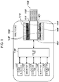
- the present configuration example will be described with reference to FIG. 9 .
- FIG. 9 is a schematic diagram schematically illustrating the ninth configuration example of the inhaler device.
- an inhaler device 100J according to the present configuration example includes a power supply part 111J, a sensor part 112J, a notification part 113J, a memory part 114J, a communication part 115J, a control part 116J, a susceptor 161J, an electromagnetic induction source 162J, and a holder part 140J.
- the user inhales in a state where a stick-type substrate 150J is held by the holder part 140J.
- the respective structural elements will be described sequentially.
- the power supply part 111J, the sensor part 112J, the notification part 113J, the memory part 114J, the communication part 115J, the control part 116J, and the holder part 140J are substantially the same as the respective corresponding structural elements included in the inhaler device 100E according to the fourth configuration example.
- the stick-type substrate 150J has a structure similar to that of the stick-type substrate 150E according to the fourth configuration example.
- the stick-type substrate 150J includes the susceptor 161J.
- the susceptor 161J produces heat through electromagnetic induction.
- the susceptor 161J is comprised of conductive material such as metal.
- the susceptor 161J may be pieces of metal.
- the susceptor 161J is disposed near the aerosol source. In the example illustrated in FIG. 9 , the susceptor 161J is included in a substrate part 151J of the stick-type substrate 150J.
- the electromagnetic induction source 162J causes the susceptor 161J to produce heat through electromagnetic induction.
- the electromagnetic induction source 162J is comprised of, for example, a coil-shaped conductive wire.
- the electromagnetic induction source 162J is disposed so that the electromagnetic induction source 162J is wound around the outer circumference of the holder part 140J.
- the electromagnetic induction source 162J generates a magnetic field when the power supply part 111J supplies alternating current.
- the electromagnetic induction source 162J is disposed at a position that allows an internal space 141J of the holder part 140J to overlap the generated magnetic field.
- eddy currents are generated in the susceptor 161J and Joule heat is produced when the magnetic field is generated in a state where the stick-type substrate 150J is held by the holder part 140J. Subsequently, such Joule heat makes it possible to heat and atomize the aerosol source included in the stick-type substrate 150J, thereby generating the aerosol.
- the electric power may be supplied and the aerosol may be generated in a case where the sensor part 112J has detected predetermined user input. The user becomes capable of inhalation when the temperature of the stick-type substrate 150J heated by the susceptor 161J and the electromagnetic induction source 162J through induction heating reaches a predetermined temperature.
- the supply of the electric power may be stopped in a case where the sensor part 112J has detected predetermined user input.
- the electric power may be supplied and the aerosol may be generated during a period in which the sensor part 112J is detecting the user's inhalation.
- a hybrid inhaler device is an inhaler device that has both features of the substrate-integrated inhaler device and features of the inhaler device with the external substrate.
- a tenth configuration example which will be described below, is a configuration example of the hybrid inhaler device. Next, the present configuration example will be described with reference to FIG. 10 .
- FIG. 10 is a schematic diagram schematically illustrating the tenth configuration example of the inhaler device.
- an inhaler device 100K according to the present configuration example includes a power supply part 111K, a sensor part 112K, a notification part 113K, a memory part 114K, a communication part 115K, a control part 116K, a liquid guide part 122K, a liquid storage part 123K, a heater part 121K-1, a heater part 121K-2, a holder part 140K, and a heat insulation part 144K.
- an airflow path 180K is formed in the inhaler device 100K. The user inhales in a state where a stick-type substrate 150K is held by the holder part 140K.
- the respective structural elements will be described sequentially.
- the power supply part 111K, the sensor part 112K, the memory part 114K, the communication part 115K, the control part 116K, the heater part 121K-1, the liquid guide part 122K, and the liquid storage part 123K are substantially the same as the respective corresponding structural elements included in the inhaler device 100A according to the first configuration example.
- the heater part 121K-2 is substantially the same as the heater part 121E according to the fourth configuration example.
- the stick-type substrate 150K is substantially the same as the stick-type substrate 150E according to the fourth configuration example.
- the holder part 140K has a structure similar to that of the holder part 140E according to the fourth configuration example.
- the holder part 140K includes a bottom part 143K that has an air outlet hole 182K of the airflow path 180.
- the air outlet hole 182K allows an internal space 141K of the holder part 140K to communicate with the airflow path 180K.
- the airflow path 180K is a flow path of air to be inhaled by the user.
- the airflow path 180K has a tube-like structure having an air inlet hole 181K and the air outlet hole 182K at both ends of the airflow path 180K.
- the air inlet hole 181K is an inlet of air into the airflow path 180K
- the air outlet hole 182K is an outlet of the air from the airflow path 180K.
- the air inlet hole 181K is made at any position in the inhaler device 100K.
- the air outlet hole 182K is made in the bottom part 143K of the holder part 140K.
- the liquid guide part 122K is interposed in the airflow path 180K.
- An aerosol generated by the heater part 121K-1 is mixed with the air flowed in through the air inlet hole 181K.
- the mixed fluid including the aerosol and the air is conveyed to the internal space 141K of the holder part 140 through the air outlet hole 182K when the user inhales.
- the mixed fluid including the aerosol and the air that has been conveyed to the internal space 141K of the holder part 140 reaches the inside of the mouth of the user together with an aerosol generated by the heater part 121K-2.
- the aerosol through the vibration of the vibrator part 127 according to the third configuration example or through the induction heating caused by the susceptor 161I and the electromagnetic induction source 162I according to the eighth configuration example, instead of the heating caused by the heater part 121K-1.
- the heating caused by the heater part 121K-2 it is also possible to generate the aerosol through the induction heating caused by the susceptor 161J and the electromagnetic induction source 162K according to the ninth configuration example.
- FIG. 11 is a block diagram illustrating a configuration example of a system 1 according to an embodiment of the present invention. As illustrated in FIG. 11 , the system 1 includes the inhaler device 100, a terminal device 200, and a server 300.
- the inhaler device 100 is a device for generating material to be inhaled by a user.
- the inhaler device 100 is configured as the inhaler device 100E according to the fourth configuration example. That is, the inhaler device 100 according to the present embodiment has a configuration that is similar to that of the inhaler device 100E according to the fourth configuration example.
- the configuration of the inhaler device 100 the following description will mainly illustrate points to be added to or emphasized in the configuration described above as the fourth configuration example. Note that "E", which is the alphabetical letter corresponding to the fourth configuration example, will be omitted below from the reference signs added to the structural elements according to the fourth configuration example for easy description.
- the notification part 113 notifies information to the user.
- the notification part 113 includes at least any of a display device that displays information, a light-emitting device that emits light, a vibration device that vibrates, or a sound output device that outputs sound.
- An example of the display device is a display.
- An example of the light-emitting device is an LED.
- An example of the vibration device is an eccentric motor.
- An example of the sound output device is a speaker.
- the notification part 113 notifies information to the user by outputting information that is input from the control part 116.
- the notification part 113 displays information to be notified to the user, emits a pattern of light in accordance with the information to be notified to the user, vibrates in a vibration pattern in accordance with the information to be notified to the user, or outputs sound of the information to be notified to the user.
- the vibration pattern herein is a concept including an amplitude, a frequency, a vibration timing, and the like.
- the communication part 115 is an example of a wireless communication part that transmits/receives information wirelessly.
- the communication part 115 transmits/receives information to/from the terminal device 200 wirelessly.
- the sensor part 112 further includes a first temperature sensor, a second temperature sensor, an electric power measurement sensor, an image sensor, and a light sensor.
- the first temperature sensor detects an environment temperature that is an ambient temperature of the inhaler device 100.
- the first temperature sensor may detect the environment temperature on the basis of an electric resistance of a wire.
- the second temperature sensor detects the temperature of the heater part 121.
- the second temperature sensor may detect the temperature of the heater part 121 on the basis of an electric resistance of a conducting track of the heater part 121.
- the second temperature sensor may detect the temperature of the heater part 121 as the temperature of the stick-type substrate 150 held by the holder part 140.
- the temperature of the heater part 121 may be detected on the basis of an electric resistance of the heater part 121.
- the electric power measurement sensor measures electric power to be input to other structural elements from the power supply part 111.
- the image sensor is a sensor that picks up an image.
- the image sensor picks up an image of, for example, the internal space 141 of the holder part 140.
- the light sensor is a sensor that detects light. The light sensor detects, for example, a light amount of the internal space 141 of the holder part 140.
- the control part 116 controls a process of notifying information regarding cleaning of the inhaler device 100 to the user. This point will be described later in detail.
- the terminal device 200 is an information processing device to be operated by the user.
- the terminal device 200 transmits/receives information to/from the inhaler device 100 and the server 300 and outputs information based on the communication to the user.
- the terminal device 200 is comprised of a smartphone, a tablet terminal, a wearable device, or the like.
- the terminal device 200 includes a sensor part 210, a notification part 220, a communication part 230, a memory part 240, and a control part 250.
- the sensor part 210 detects various kinds of information regarding the terminal device 200. The sensor part 210 then outputs the detected information to the control part 250.
- the sensor part 210 includes an input part that accepts information that is input by the user.
- the input part includes, for example, at least any of a button, a keyboard, a touch panel, or a microphone.
- the sensor part 210 further includes position information acquiring part that acquires position information indicating the position of the terminal device 200.
- the position information acquiring part detects, for example, position information comprised of the latitude and the longitude of the device by receiving Global Navigation Satellite System (GNSS) signals from GNSS satellites (e.g., Global Positioning System (GPS) signals from GPS satellites).
- GNSS Global Navigation Satellite System
- GPS Global Positioning System
- the notification part 220 notifies information to the user.
- the notification part 220 includes at least any of a display device that displays information, a light-emitting device that emits light, a vibration device that vibrates, or a sound output device that outputs sound.
- An example of the display device is a display.
- An example of the light-emitting device is an LED.
- An example of the vibration device is an eccentric motor.
- An example of the sound output device is a speaker.
- the notification part 220 notifies information to the user by outputting information that is input from the control part 250.
- the notification part 220 displays information to be notified to the user, emits a pattern of light in accordance with the information to be notified to the user, vibrates in a vibration pattern in accordance with the information to be notified to the user, or outputs sound of the information to be notified to the user.
- the terminal device 200 such as a smartphone has higher performance and may have a large display or a surround speaker mounted thereon. That is, the notification part 220 has a higher expressive power than the notification part 113 in, for example, including a display that is absent in the notification part 113 or that is larger than a display of the notification part 113.
- the communication part 230 is a communication interface for allowing transmission/reception of information between the terminal device 200 and another device.
- the communication part 230 performs communication in conformity with any wired or wireless communication standard.
- a communication standard for example, a wireless local area network (LAN), a wired LAN, Wi-Fi (registered trademark), Bluetooth (registered trademark), or the like may be adopted.
- the communication part 230 is an example of a wireless communication part that transmits/receives information wirelessly.
- the communication part 230 transmits/receives information to/from the inhaler device 100 wirelessly.
- the communication part 230 also transmits/receives information to/from the server 300 wirelessly.
- the memory part 240 stores various kinds of information for operation of the terminal device 200.
- the memory part 240 may be comprised of, for example, a non-volatile storage medium such as flash memory.
- the control part 250 functions as an arithmetic processing unit and a control device, and controls overall operations inside the terminal device 200 in accordance with various programs.
- the control part 250 is implemented as an electronic circuit such as a central processing unit (CPU) or a microprocessor, for example.
- the control part 250 may include read-only memory (ROM) that stores a program, an arithmetic parameter, and the like to be used, and random-access memory (RAM) that temporarily stores a parameter or the like that varies appropriately.
- ROM read-only memory
- RAM random-access memory
- Examples of the processes controlled by the control part 250 include processing of information detected by the sensor part 210, notification of information by the notification part 220, transmission/reception of information by the communication part 230, and storing/readout of information by the memory part 240.
- the control part 250 also controls other processes to be performed by the terminal device 200 such as inputting information to the respective structural elements and a process based on information output from the respective structural elements.
- the server 300 is a device that transmits information requested from the terminal device 200 to the terminal device 200.
- the server 300 is, for example, comprised of a web server.
- the inhaler device 100 acquires inhaler device information. On the basis of the inhaler device information, the inhaler device 100 then controls a process of transmitting cleaning necessity information by using the communication part 115. More specifically, on the basis of the inhaler device information, the inhaler device 100 determines whether the cleaning necessity information is to be notified to a user. At a timing at which the notification is determined to be issued, the inhaler device 100 wirelessly transmits the cleaning necessity information to the terminal device 200.
- the inhaler device information herein is information regarding the inhaler device 100.
- the cleaning necessity information is information indicating necessity of cleaning the inhaler device 100. Such information will be described later in detail.
- the terminal device 200 Upon reception of the cleaning necessity information from the inhaler device 100, the terminal device 200 notifies the received cleaning necessity information to the user by using the notification part 220.
- the notification part 220 displays the cleaning necessity information, outputs sound of the cleaning necessity information, emits a pattern of light in accordance with the cleaning necessity information, or vibrates in a vibration pattern in accordance with the cleaning necessity information.
- the inhaler device 100 can notify the cleaning necessity information to the user via the terminal device 200.
- the terminal device 200 has a higher expressive power than the inhaler device 100 in, for example, that a display that is absent in the inhaler device 100 or that is larger than a display of the inhaler device 100 is mounted thereon.
- usability regarding cleaning can be improved.
- the cleaning necessity information may be first cleaning necessity information (corresponding to first information).
- the first cleaning necessity information is information indicating that it is highly necessary to clean the inhaler device 100.
- the first cleaning necessity information is information that recommends cleaning of the inhaler device 100. By being notified of the first cleaning necessity information, the user can do the cleaning at an appropriate timing.
- the cleaning necessity information may be second cleaning necessity information (corresponding to second information).
- the second cleaning necessity information is information indicating that it is becoming necessary to clean the inhaler device 100.
- the second cleaning necessity information is information that recommends cleaning of the inhaler device 100 in the near future.
- the second cleaning necessity information may be information that recommends preparation of the cleaning.
- the preparation of the cleaning is, for example, purchasing or carrying cleaning items to be used during cleaning of the inhaler device 100. By being notified of the second cleaning necessity information, the user can prepare for the cleaning in advance.
- the cleaning necessity information may include information regarding the timing for cleaning the inhaler device 100.
- the cleaning necessity information may include information indicating the date and time for cleaning the inhaler device 100, information indicating the remaining number of times of inhalation before it is necessary to do the cleaning, and the like.
- the first cleaning necessity information may also include, for example, information indicating that the timing for cleaning the inhaler device 100 has come.
- the second cleaning necessity information may include, for example, information indicating that the timing for cleaning the inhaler device 100 will come in the near future. With such a configuration, the user can easily know the timing for cleaning.
- the inhaler device information may include the number of times of preheating executed by the inhaler device 100 to enable the user to inhale by using the inhaler device 100.
- the temperature of the stick-type substrate 150 heated by the heater part 121 (more precisely, the temperature of the substrate part 151 that is a heating target of the heater part 121) or the temperature of the heater part 121 that executes preheating reaches (e.g., exceeds) a predetermined temperature (hereinafter also referred to as inhalation enabled temperature)
- the preheating is the heating executed until the temperature of the stick-type substrate 150 or the temperature of the heater part 121 reaches the predetermined temperature.
- the inhalation enabled temperature of the stick-type substrate 150 and the inhalation enabled temperature of the heater part 121 may be equal to each other or may be different from each other.
- the inhaler device 100 transmits the first cleaning necessity information as the cleaning necessity information.
- the first cleaning necessity information can be notified to the user via the terminal device 200.
- the preheating is executed every time the stick-type substrate 150 is inserted into the holder part 140 before the user inhales. After the preheating, the stick-type substrate 150 is continuously heated while the user is inhaling. Hereinafter, heating executed after the preheating will be also referred to as main heating. As an aerosol is generated from the stick-type substrate 150 by the preheating and the main heating, the stick-type substrate 150 becomes brittle. Thus, after the user's inhalation, when the stick-type substrate 150 is drawn out of the holder part 140, the remaining content of the stick-type substrate 150 (hereinafter also referred to as butt) drops and is deposited in the holder part 140.
- butt the remaining content of the stick-type substrate 150
- a portion of the stick-type substrate 150, the portion into which the blade-shaped heater part 121 is stuck, is likely to be brittle, and the butt is likely to drop therefrom.
- the number of times of preheating can be regarded as being equal to the number of times of the user's inhalation and the number of times the stick-type substrate 150 is inserted into and removed from the holder part 140.
- the amount of butt deposited in the holder part 140 can be larger.
- the number of times of preheating at which the amount of deposited butt is assumed to be so large that cleaning is necessary is set as the first threshold. This makes it possible to notify the first cleaning necessity information to the user at an appropriate timing.
- the first threshold may be a fixed value or may vary depending on the type of the inhaler device 100, the type of the stick-type substrate 150 that is preheated, or the like.
- the inhaler device 100 may transmit the second cleaning necessity information as the cleaning necessity information.
- the second cleaning necessity information can be notified to the user via the terminal device 200.
- the number of times of preheating at which the amount of deposited butt is assumed to become so large that cleaning will be necessary in the near future is set as the second threshold. This makes it possible to notify the second cleaning necessity information to the user at an appropriate timing.
- the second threshold may be a fixed value or may vary depending on the type of the inhaler device 100, the type of the stick-type substrate 150 that is preheated, or the like.
- the second threshold may be set on the basis of the first threshold, such as 70% of the first threshold.
- the number of times of preheating may be initialized in a case where a predetermined user operation (hereinafter also referred to as reset operation) is performed.
- the reset operation may be performed on the inhaler device 100 or may be performed on the terminal device 200.
- the reset operation is an operation of inputting predetermined information to the sensor part 112 or the sensor part 210, such as a press-and-hold operation of a button.
- To initialize the number of times of preheating means to set the counted number of times of preheating to zero.
- the reset operation is performed, for example, when the inhaler device 100 is cleaned.
- the inhaler device 100 may count the number of times of preheating in a case where it is determined that preheating is executed for a substrate that contributes, when being heated, to generation of material to be inhaled by the user.
- the material is, for example, a member including an aerosol source and corresponds to the stick-type substrate 150.
- the inhaler device 100 counts the number of times of preheating in a case where the preheating is executed in a state where the stick-type substrate 150 is held by the holder part 140.
- the number of times of preheating is not counted. Accordingly, the correlation between the counted number of times of preheating and the amount of butt deposited in the holder part 140 can be maintained, and thus, it is possible to notify the cleaning necessity information based on the number of times of preheating at an appropriate timing.
- the light sensor may detect light emitted when the heater part 121 produces heat.
- a light-emitting part and a light sensor may be provided so as to face each other with the internal space 141 of the holder part 140 interposed therebetween, and the light sensor may detect light emitted by the light-emitting part.
- the stick-type substrate 150 In a case where the stick-type substrate 150 is held by the holder part 140, light emitted by the heater part 121 or the light-emitting part is blocked by the stick-type substrate 150, and the light amount detected by the light sensor becomes lower than the threshold. On the other hand, in a case where the stick-type substrate 150 is not held by the holder part 140, light emitted by the heater part 121 or the light-emitting part directly reaches the light sensor, and the light amount detected by the light sensor becomes higher than the threshold.
- the inhaler device 100 (e.g., the memory part 114) stores the number of times of preheating. Then, every time the preheating is executed, the inhaler device 100 increments the stored number of times of preheating and updates the stored number. Thus, for example, even when the power is turned on/off between the last-time preheating and the current preheating, the number of times of preheating can be continuously counted.
- the inhaler device information may include the time taken for the temperature of the heating target or the temperature of the heater part 121 that executes preheating to reach a predetermined temperature when the inhaler device 100 executes the preheating to enable the user to inhale by using the inhaler device 100.
- the predetermined temperature is the above-described inhalation enabled temperature.
- the time taken for the temperature to reach the inhalation enabled temperature is hereinafter also referred to as a time required for preheating.
- the heating target is the stick-type substrate 150 (more precisely, the substrate part 151 of the stick-type substrate 150).
- the time required for preheating is a time taken from the start of the preheating until the temperature of the stick-type substrate 150 or the temperature of the heater part 121 reaches the inhalation enabled temperature.
- the temperature of the heater part 121 is detected, for example, by the second temperature sensor included in the sensor part 112.
- the temperature of the stick-type substrate 150 is estimated, for example, on the basis of the temperature of the heater part 121 detected by the second temperature sensor included in the sensor part 112.
- the inhaler device 100 transmits the first cleaning necessity information as the cleaning necessity information.
- the first cleaning necessity information can be notified to the user via the terminal device 200.
- the time required for preheating is longer. This is because the heat produced by the heater part 121 propagates not only to the stick-type substrate 150 held by the holder part 140 but also to the butt deposited in the holder part 140.
- the time required for preheating at which the amount of deposited butt is assumed to be so large that cleaning is necessary is set as the third threshold. This makes it possible to notify the first cleaning necessity information to the user at an appropriate timing.
- the third threshold may be a fixed value or may vary depending on the type of the inhaler device 100, the type of the stick-type substrate 150 that is preheated, or the like. Furthermore, the inhaler device 100 may set the third threshold on the basis of the environment temperature. As an example, the inhaler device 100 sets the third threshold to a smaller value as the environment temperature is higher. This is because the temperature of the stick-type substrate 150 and the temperature of the heater part 121 are likely to increase, shortening the time required for preheating, as the environment temperature is higher. As another example, the inhaler device 100 sets the third threshold to a larger value as the environment temperature is lower.
- the cleaning necessity information can be notified to the user at an appropriate timing in accordance with the environment temperature.
- the environment temperature is detected by, for example, the first temperature sensor included in the sensor part 112.
- the inhaler device 100 may transmit the second cleaning necessity information as the cleaning necessity information.
- the second cleaning necessity information can be notified to the user via the terminal device 200.
- the time required for preheating at which the amount of deposited butt is assumed to become so large that cleaning will be necessary in the near future is set as the fourth threshold. This makes it possible to notify the second cleaning necessity information to the user at an appropriate timing.
- the fourth threshold may be a fixed value or may vary depending on the type of the inhaler device 100, the type of the stick-type substrate 150 that is preheated, or the like.
- the fourth threshold may be set on the basis of the third threshold, such as 70% of the third threshold.
- the inhaler device 100 may set the fourth threshold on the basis of the environment temperature from reasons similar to the reasons described above regarding the third threshold.
- the inhaler device information may include the electric power used for the temperature of the heating target or the temperature of the heater part 121 that executes preheating to reach a predetermined temperature when the inhaler device 100 executes the preheating so as to enable the user to inhale by using the inhaler device 100.
- the predetermined temperature is the above-described inhalation enabled temperature.
- the electric power used for the temperature to reach the inhalation enabled temperature is hereinafter also referred to as an electric power required for preheating.
- the heating target is the stick-type substrate 150 (more precisely, the substrate part 151 of the stick-type substrate 150).
- the electric power required for preheating is the total amount of electric power that is input to the heater part 121 from the start of the preheating until the temperature of the stick-type substrate 150 or the temperature of the heater part 121 reaches the inhalation enabled temperature.
- the electric power that is input to the heater part 121 is measured, for example, by an electric power measurement sensor in included in the sensor part 112.
- the inhaler device 100 transmits the first cleaning necessity information as the cleaning necessity information.
- the first cleaning necessity information can be notified to the user via the terminal device 200.
- the electric power required for preheating is longer. This is because the heat produced by the heater part 121 propagates not only to the stick-type substrate 150 held by the holder part 140 but also to the butt deposited in the holder part 140.
- the electric power required for preheating at which the amount of deposited butt is assumed to be so large that cleaning is necessary is set as the fifth threshold. This makes it possible to notify the first cleaning necessity information to the user at an appropriate timing.
- the fifth threshold may be a fixed value or may vary depending on the type of the inhaler device 100, the type of the stick-type substrate 150 that is preheated, or the like. Furthermore, the inhaler device 100 may set the fifth threshold on the basis of the environment temperature. As an example, the inhaler device 100 sets the fifth threshold to a smaller value as the environment temperature is higher. This is because the temperature of the stick-type substrate 150 and the temperature of the heater part 121 are likely to increase, decreasing the electric power required for preheating, as the environment temperature is higher. As another example, the inhaler device 100 sets the fifth threshold to a larger value as the environment temperature is lower.
- the cleaning necessity information can be notified to the user at an appropriate timing in accordance with the environment temperature.
- the inhaler device 100 may transmit the second cleaning necessity information as the cleaning necessity information.
- the second cleaning necessity information can be notified to the user via the terminal device 200.
- the electric power required for preheating at which the amount of deposited butt is assumed to become so large that cleaning will be necessary in the near future is set as the sixth threshold. This makes it possible to notify the second cleaning necessity information to the user at an appropriate timing.
- the sixth threshold may be a fixed value or may vary depending on the type of the inhaler device 100, the type of the stick-type substrate 150 that is preheated, or the like.
- the sixth threshold may be set on the basis of the fifth threshold, such as 70% of the fifth threshold.
- the inhaler device 100 may set the sixth threshold on the basis of the environment temperature from reasons similar to the reasons described above regarding the fifth threshold.
- the inhaler device 100 may switch a notification means of the cleaning necessity information. More specifically, in a case where the inhaler device 100 and the terminal device 200 are wirelessly connected to each other, the inhaler device 100 transmits the cleaning necessity information to the terminal device 200 by using the communication part 115. On the other hand, in a case where the inhaler device 100 and the terminal device 200 are not wirelessly connected to each other, the inhaler device 100 notifies the cleaning necessity information by using the notification part 113. Thus, the cleaning necessity information can be notified via the terminal device 200 having a high expressive power during wireless connection. In addition, not during wireless connection, although the expressive power is lower than that in a case where the terminal device 200 notifies the information, the cleaning necessity information can be notified at least without delay.
- the inhaler device 100 does not necessarily notify the cleaning necessity information by using the notification part 113. That is, in a case where the inhaler device 100 and the terminal device 200 are wirelessly connected to each other, instead of notification of the cleaning necessity information by using the notification part 113, the inhaler device 100 may only wirelessly transmit the cleaning necessity information by using the communication part 115. This makes it possible to suppress power consumption for notification by the inhaler device 100.
- the inhaler device 100 may notify the cleaning necessity information by using the notification part 113 even in a case where the inhaler device 100 and the terminal device 200 are wirelessly connected to each other. That is, in a case where the inhaler device 100 and the terminal device 200 are wirelessly connected to each other, in addition to notification of the cleaning necessity information by using the notification part 113, the inhaler device 100 may wirelessly transmit the cleaning necessity information by using the communication part 115. This makes it possible to notify the information to the user more reliably than in a case where notification is issued by any one of the inhaler device 100 or the terminal device 200.
- the terminal device 200 notifies the cleaning necessity information to the user by using the notification part 220. Then, in a case where information indicating not to clean the inhaler device 100 is input to the sensor part 210, the terminal device 200 performs setting for notifying the cleaning necessity information again by using the notification part 220. As an example, the terminal device 200 may automatically perform setting, for example, by setting the timing for notifying the cleaning necessity information again after a predetermined time. As another example, the terminal device 200 may receive user input of information indicating the timing for notifying the cleaning necessity information again and may perform setting on the basis of the input information. In any case, a reminder can be set in a situation where it is difficult to execute cleaning at a timing at which the cleaning necessity information is notified, for example, because the user does not carry cleaning items with them.
- the terminal device 200 may also notify information indicating a method for cleaning the inhaler device 100 by using the notification part 220.
- Such information will be hereinafter also referred to as cleaning method information.
- the cleaning method information may include a method of using cleaning items to be used for cleaning the inhaler device 100, a method of disassembling the inhaler device 100, and the like.
- the terminal device 200 notifies the cleaning method information together with the cleaning necessity information. With such a configuration, the user can know the cleaning method easily at a timing for cleaning the inhaler device 100.
- the terminal device 200 may transmit information for requesting the cleaning method information.
- the terminal device 200 can acquire the cleaning method information and can notify the cleaning method information to the user.
- the information for requesting the cleaning method information may be transmitted to the server 300.
- the information for requesting the cleaning method information may include, for example, information indicating the type of the inhaler device 100.
- the server 300 generates the cleaning method information in accordance with the type of the inhaler device 100. Then, in a case where the server 300 transmits the cleaning method information as a reply, the terminal device 200 notifies the cleaning necessity information received from the server 300 to the user.
- the information for requesting the cleaning method information may also be transmitted to the inhaler device 100.
- the inhaler device 100 transmits the cleaning method information to the terminal device 200 in response to the request. It is needless to say that the inhaler device 100 may spontaneously transmit the cleaning method information without being requested. For example, the inhaler device 100 may transmit the cleaning method information together with the cleaning necessity information.
- the terminal device 200 upon reception of the cleaning method information from the inhaler device 100, the terminal device 200 notifies the user of the received cleaning method information. With such a configuration, the terminal device 200 can notify the cleaning method information to the user even in a situation where it is difficult to communicate with the server 300.
- the terminal device 200 may also notify information on a store that sells cleaning items to be used for cleaning the inhaler device 100 by using the notification part 220.
- Such information will be hereinafter also referred to as store information.
- the store information may include information indicating the location of a store near from the location of the inhaler device 100, information indicating sale prices at each store, and the like.
- the store herein may be a virtual store such as an online shop. This can make it possible for the user to acquire cleaning items easily.
- the terminal device 200 may transmit information for requesting the store information to the server 300.
- the terminal device 200 may transmit information for requesting the store information to the server 300.
- the information for requesting the store information may include, for example, information indicating the type of the inhaler device 100, the location information of the terminal device 200, and the like.
- the server 300 searches for a store that sells cleaning items in accordance with the type of the inhaler device 100 and that is nearest from the user, and generates the store information. Then, in a case where the server 300 transmits the store information as a reply, the terminal device 200 notifies the store information received from the server 300 to the user. With such a configuration, the user can acquire cleaning items easily at a timing for cleaning the inhaler device 100.
- FIG. 12 is a sequence chart illustrating an example of a process flow of notifying cleaning necessity information executed by the system 1 according to the present embodiment. As illustrated in FIG. 12 , this sequence involves the inhaler device 100, the terminal device 200, and the server 300.
- the inhaler device 100 acquires inhaler device information (step S102). For example, on the basis of a result of detection by the sensor part 112, the inhaler device 100 acquires at least any of the number of times of preheating, the time required for preheating, or the electric power required for preheating.
- the inhaler device 100 determines whether cleaning necessity information is to be notified to a user (step S104). For example, the inhaler device 100 compares the number of times of preheating with the first threshold or the second threshold, compares the time required for preheating with the third threshold or the fourth threshold, and compares the electric power required for preheating with the fifth threshold or the sixth threshold. In a case where at least any of the number of times of preheating, the time required for preheating, or the electric power required for preheating reaches (e.g., exceeds) the comparison-target threshold, the inhaler device 100 determines that the cleaning necessity information is to be notified.
- the inhaler device 100 determines that the cleaning necessity information is not to be notified.
- step S104/NO the process returns to step S102 again.
- step S104/YES the inhaler device 100 determines whether wireless connection with the terminal device 200 is established (step S106).
- the inhaler device 100 transmits the cleaning necessity information to the terminal device 200 (step S108).
- the terminal device 200 transmits information for requesting cleaning method information and information for requesting store information of cleaning items to the server 300 (step S110).
- the server 300 transmits the cleaning method information and the store information requested from the terminal device 200 as a reply to the terminal device 200 (step S112).
- the terminal device 200 notifies the received cleaning necessity information, cleaning method information, and store information to the user by using the notification part 220 (step S114).
- step S106/NO If it is determined that the inhaler device 100 and the terminal device 200 are not wirelessly connected to each other (step S106/NO), the inhaler device 100 notifies the cleaning necessity information to the user by using the notification part 113 (step S116).
- the inhaler device 100 in the above embodiment is described to be configured as the inhaler device 100E according to the fourth configuration example, the present invention is not limited to this example.
- the inhaler device 100 may also be configured as any of the other substrate-integrated inhaler devices according to the fifth to seventh configuration examples.
- the inhaler device 100 may also be configured as any of the inhaler devices according to the first to third configuration examples and the eighth to tenth configuration examples.
- the inhaler device 100 in the above embodiment controls the process of notifying the cleaning necessity information on the basis of the inhaler device information
- the present invention is not limited to this example.
- the inhaler device 100 may transmit the inhaler device information to the terminal device 200.
- the terminal device 200 may control the process of notifying the cleaning necessity information on the basis of the inhaler device information. More specifically, the terminal device 200 determines whether the cleaning necessity information is to be notified to the user on the basis of the inhaler device information. Then, at a timing that is determined as a notification timing, the terminal device 200 notifies the cleaning necessity information to the user by using the notification part 220.
- the cleaning necessity information can be notified to the user via the terminal device 200 as in the above embodiment, and thus, it is possible to improve usability regarding cleaning.
- the process executed by the devices described herein may be implemented by using any of software, hardware, and a combination of software and hardware.
- Programs constituting software are, for example, stored in advance storage media (non-transitory media) provided inside or outside the devices. Then, for example, when being executed by a computer, each program is loaded into a RAM and executed by a processor such as a CPU. Examples of the storage media include a magnetic disk, an optical disk, a magnetooptical disk, a flash memory, and the like.
- the above computer programs may be distributed, for example, via a network without using storage media.
Landscapes
- Engineering & Computer Science (AREA)
- Computer Networks & Wireless Communication (AREA)
- Disinfection, Sterilisation Or Deodorisation Of Air (AREA)
- Medicinal Preparation (AREA)
Abstract
Description
- The present invention relates to an inhaler device, a terminal device, an information processing method, and a program.
- An inhaler device for generating material to be inhaled by a user, such as an electronic cigarette or a nebulizer, is now widely spread. For example, by using a substrate including an aerosol source for generating an aerosol, a flavor source for adding a flavor component to a generated aerosol, or the like, the inhaler device generates an aerosol to which the flavor component is added. The user can taste the flavor by inhaling (hereinafter also referred to as "puffing") the aerosol to which the flavor component is added, which is generated by the inhaler device.
- Aerosol generation may make the substrate brittle, and part of the substrate may remain and be deposited inside the inhaler device. The inhaler device is therefore desirably cleaned as appropriate. However, in order to determine the necessity of cleaning by him/herself, the user may be bothered, for example, to open the cover of the inhaler device and to check the amount of deposit remaining therein. Thus, as an example of a technique to reduce the bother,
Patent Literature 1 below discloses a technique by which an inhaler device displays information for recommending cleaning in accordance with the number of times the inhaler device is used and makes the inhaler device unavailable unless cleaned. - Patent Literature 1: International Publication No.
1998/023171 - The inhaler device has various restrictions for improving portability or the like. One of the restricted functions is an expressive power of information. For example, only a simple output device, such as a light-emitting device, may be mounted on the inhaler device as a device for notifying information to the user. Even when the user is notified of information regarding cleaning with the restricted expressive power, it may be difficult to understand.
- The present invention has been made in view of the above issue, and an object of the present invention is to provide a mechanism with which it is possible to improve usability regarding cleaning of the inhaler device.
- In order to solve the above problem, an aspect of the present invention provides an inhaler device including: a wireless communication part that transmits/receives information wirelessly; and a control part that acquires information regarding the inhaler device and controls, on the basis of the acquired information regarding the inhaler device, a process of transmitting information indicating necessity of cleaning the inhaler device by using the wireless communication part.
- The information regarding the inhaler device may include a number of times of preheating executed by the inhaler device to enable a user to inhale by using the inhaler device, and the control part may control the wireless communication part to transmit first information as the information indicating necessity of cleaning the inhaler device in a case where the number of times of preheating reaches a first threshold.
- The number of times of preheating may be initialized in a case where a predetermined user operation is performed.
- The control part may count the number of times of preheating in a case where it is determined that the preheating is executed for a substrate that contributes, when being heated, to generation of material to be inhaled by the user.
- The inhaler device may further include a memory part. The memory part may store the number of times of preheating.
- The control part may control the wireless communication part to transmit second information as the information indicating necessity of cleaning the inhaler device in a case where the number of times of preheating reaches a second threshold that is lower than the first threshold.
- The information regarding the inhaler device may include a time taken for a temperature of a heating target or a temperature of a heater part that executes preheating to reach a predetermined temperature when the inhaler device executes the preheating to enable a user to inhale by using the inhaler device, and the control part may control the wireless communication part to transmit first information as the information indicating necessity of cleaning the inhaler device in a case where the time taken for the temperature of the heating target or the temperature of the heater part to reach the predetermined temperature reaches a third threshold.
- The control part may set the third threshold on the basis of an environment temperature that is an ambient temperature of the inhaler device.
- The control part may control the wireless communication part to transmit second information as the information indicating necessity of cleaning the inhaler device in a case where the time taken for the temperature of the heating target or the temperature of the heater part to reach the predetermined temperature reaches a fourth threshold that is lower than the third threshold.
- The information regarding the inhaler device may include an electric power used for a temperature of a heating target or a temperature of a heater part that executes preheating to reach a predetermined temperature when the inhaler device executes the preheating to enable a user to inhale by using the inhaler device, and the control part may control the wireless communication part to transmit first information as the information indicating necessity of cleaning the inhaler device in a case where the electric power used for the temperature of the heating target or the temperature of the heater part to reach the predetermined temperature reaches a fifth threshold.
- The control part may set the fifth threshold on the basis of an environment temperature that is an ambient temperature of the inhaler device.
- The control part may control the wireless communication part to transmit second information as the information indicating necessity of cleaning the inhaler device in a case where the electric power used for the temperature of the heating target or the temperature of the heater part to reach the predetermined temperature reaches a sixth threshold that is lower than the fifth threshold.
- The inhaler device may include a notification part that notifies information to a user. The control part may control the wireless communication part to transmit the information indicating necessity of cleaning the inhaler device to another device in a case where the inhaler device and the other device are wirelessly connected to each other and may control the notification part to notify the information indicating necessity of cleaning the inhaler device in a case where the inhaler device and the other device are not wirelessly connected to each other.
- The control part may not notify the information indicating necessity of cleaning the inhaler device by using the notification part in a case where the inhaler device and the other device are wirelessly connected to each other.
- The notification part may include at least any of a display device, a light-emitting device, a vibration device, or a sound output device.
- The control part may control the wireless communication part to transmit information indicating a method for cleaning the inhaler device.
- The information indicating necessity of cleaning the inhaler device may include information regarding a timing for cleaning the inhaler device.
- In order to solve the above problem, another aspect of the present invention provides a terminal device including: a wireless communication part that transmits/receives information wirelessly; a notification part that notifies information to a user; and a control part that controls the notification part to notify information indicating necessity of cleaning an inhaler device in a case where the wireless communication part receives the information indicating necessity of cleaning the inhaler device from the inhaler device.
- The terminal device may further include an input part that accepts information that is input. The control part may perform setting for notifying the information indicating necessity of cleaning the inhaler device again in a case where information indicating not to clean the inhaler device is input to the input part after the notification part notifies the information indicating necessity of cleaning the inhaler device to the user.
- The control part may control the notification part to notify information indicating a method for cleaning the inhaler device in a case where the wireless communication part further receives the information indicating the method for cleaning the inhaler device.
- The control part may control the wireless communication part to transmit information for requesting information indicating a method for cleaning the inhaler device in a case where the information indicating necessity of cleaning the inhaler device is received.
- The control part may control the wireless communication part to transmit information for requesting information on a store that sells a cleaning item to be used for cleaning the inhaler device in a case where the information indicating necessity of cleaning the inhaler device is received.
- The control part may control a process of notifying the information indicating necessity of cleaning the inhaler device by using the notification part in a case where information regarding the inhaler device is received from the inhaler device.
- In order to solve the above problem, another aspect of the present invention provides an information processing method to be executed by an inhaler device, the information processing method including: acquiring information regarding the inhaler device; and
controlling, on the basis of the acquired information regarding the inhaler device, a process of wirelessly transmitting information indicating necessity of cleaning the inhaler device. - In order to solve the above problem, another aspect of the present invention provides an information processing method to be executed by a terminal device, the method comprising notifying information indicating necessity of cleaning an inhaler device in a case where the information indicating necessity of cleaning the inhaler device is received from the inhaler device wirelessly.
- In order to solve the above problem, another aspect of the present invention provides a program for causing a computer that controls an inhaler device to function as: a wireless communication part that transmits/receives information wirelessly; and a control part that acquires information regarding the inhaler device and controls, on the basis of the acquired information regarding the inhaler device, a process of transmitting information indicating necessity of cleaning the inhaler device by using the wireless communication part.
- In order to solve the above problem, another aspect of the present invention provides a program for causing a computer to function as: a wireless communication part that transmits/receives information wirelessly; a notification part that notifies information to a user; and a control part that controls the notification part to notify information indicating necessity of cleaning an inhaler device in a case where the wireless communication part receives the information indicating necessity of cleaning the inhaler device from the inhaler device.
- As described above, according to the present invention, a mechanism with which it is possible to improve usability regarding cleaning of the inhaler device is provided.
-
- [
FIG. 1] FIG. 1 is a schematic diagram schematically illustrating a first configuration example of an inhaler device. - [
FIG. 2] FIG. 2 is a schematic diagram schematically illustrating a second configuration example of the inhaler device. - [
FIG. 3] FIG. 3 is a schematic diagram schematically illustrating a third configuration example of the inhaler device. - [
FIG. 4] FIG. 4 is a schematic diagram schematically illustrating a fourth configuration example of the inhaler device. - [
FIG. 5] FIG. 5 is a schematic diagram schematically illustrating a fifth configuration example of the inhaler device. - [
FIG. 6] FIG. 6 is a schematic diagram schematically illustrating a sixth configuration example of the inhaler device. - [
FIG. 7] FIG. 7 is a schematic diagram schematically illustrating a seventh configuration example of an inhaler device. - [
FIG. 8] FIG. 8 is a schematic diagram schematically illustrating an eighth configuration example of the inhaler device. - [
FIG. 9] FIG. 9 is a schematic diagram schematically illustrating a ninth configuration example of the inhaler device. - [
FIG. 10] FIG. 10 is a schematic diagram schematically illustrating a tenth configuration example of the inhaler device. - [
FIG. 11] FIG. 11 is a block diagram illustrating a configuration example of a system according to an embodiment of the present invention. - [
FIG. 12] FIG. 12 is a sequence chart illustrating an example of a process flow of notifying cleaning necessity information executed by the system according to the present embodiment. - Hereinafter, a preferred embodiment of the present invention will be described in detail with reference to the accompanying drawings. Note that structural elements having substantially the same functional configuration will be denoted by the same reference signs in the specification and the drawings, thereby omitting redundant descriptions.
- An inhaler device is a device for generating material to be inhaled by a user. Hereinafter, descriptions will be given in a scenario where the material generated by the inhaler device is an aerosol. Alternatively, the material generated by the inhaler device may be gas. Hereinafter, the user's inhalation of the material generated by the inhaler device will be simply referred to as "inhalation" or "puff".
- Among a plurality of configuration examples to be described below, sometimes a plurality of elements having functional configurations corresponding to each other will be denoted with reference signs including a same numeral to specify their correspondence relation, and the respective elements will be distinguished from each other by different alphabetical letters attached after the numeral, the alphabetical letters corresponding to respective configuration examples. For example, respective inhaler devices according to the plurality of configuration examples are referred to as an
inhaler device 100A according to a first configuration example, aninhaler device 100B according to a second configuration example, and aninhaler device 100D according to a third configuration example, and thereby the inhaler devices are distinguished from each other while their correspondence relation is specified. On the other hand, in a case where there is no need in particular to distinguish the plurality of elements having functional configurations corresponding to each other among the plurality of configuration examples, sometimes a reference sign including a same numeral alone may be attached. For example, in a case where there is no need in particular to distinguish among theinhaler device 100A according to the first configuration example, theinhaler device 100B according to the second configuration example, and theinhaler device 100D according to the third configuration example, they are also simply referred to as aninhaler device 100. - In addition, with regard to the plurality of elements having functional configurations corresponding to each other among the plurality of configuration examples, sometimes one of the elements according to a certain configuration example will be described first in detail, and then descriptions of the other elements according to the other configuration examples will be omitted with reference to the previous description. In this case, the omitted descriptions can be understood by appropriately replacing an alphabetical letter included in reference signs attached to the respective elements previously described with regard to a configuration example, with an alphabetical letter corresponding to a configuration example to be subsequently described. For example, in a case where the
inhaler device 100A according to the first configuration example is described in detail but descriptions of theinhaler device 100B according to the second configuration example are omitted, the omitted descriptions can be understood by replacing 100A with 100B with regard to the detailed descriptions of the first configuration example. - Hereinafter, respective configuration examples of the inhaler device will be described with reference to
FIG. 1 to FIG. 10 . - A substrate-integrated inhaler device is an inhaler device integrated with a substrate including an aerosol source. First to third configuration examples, which will be described below, are configuration examples of the substrate-integrated inhaler device.
- An inhaler device according to the present configuration example generates an aerosol by heating a liquid aerosol source. The inhaler device according to the present configuration example is comprised of two parts, which are a power supply unit and a cartridge. Next, the present configuration example will be described with reference to
FIG. 1 . -
FIG. 1 is a schematic diagram schematically illustrating the first configuration example of the inhaler device. As illustrated in FIG. T1, theinhaler device 100A according to the present configuration example includes apower supply unit 110A and acartridge 120A. Thepower supply unit 110A and thecartridge 120A are configured to be detachably attached to each other. The user inhales in a state where thecartridge 120A is attached to thepower supply unit 110A. - As illustrated in
FIG. 1 , thepower supply unit 110A includes apower supply part 111A, asensor part 112A, anotification part 113A, amemory part 114A, acommunication part 115A, and acontrol part 116A. In addition, thecartridge 120A includes aheater part 121A, aliquid guide part 122A, aliquid storage part 123A, and amouthpiece 124A. In thecartridge 120A, anairflow path 180A is formed. Next, the respective structural elements will be described sequentially. - The
power supply part 111A stores electric power. Thepower supply part 111A then supplies the electric power to the respective structural elements of theinhaler device 100A. Thepower supply part 111A may be comprised of, for example, a rechargeable battery such as a lithium ion secondary battery. Thepower supply part 111A may be charged by being connected to an external power supply via a Universal Serial Bus (USB) cable or the like. Alternatively, thepower supply part 111A may be charged through a wireless power transmission technology in a state where thepower supply part 111A is not physically connected to an electric power transmission device. In addition, thepower supply part 111A may be configured in such a manner that thepower supply part 111A is only part that is detachable from theinhaler device 100A and thepower supply part 111A is replaceable with a newpower supply part 111A. - The
sensor part 112A detects various kinds of information regarding theinhaler device 100A. Thesensor part 112A then outputs the detected information to thecontrol part 116A. As an example, thesensor part 112A may be comprised of a pressure sensor such as a condenser microphone or the like. Next, in a case where thesensor part 112A detects a negative pressure generated by the user's inhalation, thesensor part 112A outputs, to thecontrol part 116A, information indicating that the user has inhaled. As another example, thesensor part 112A may be comprised of an input device that receives information input by the user such as a button or a switch. In particular, thesensor part 112A may include a button that commands start/stop of generation of an aerosol. Thesensor part 112A then outputs the information input by the user to thecontrol part 116A. - The
notification part 113A notifies information to the user. As an example, thenotification part 113A may be comprised of a light-emitting device such as a light-emitting diode (LED). In this case, thenotification part 113A emits different patterns of light depending on its situations such as a situation where thepower supply part 111A needs to be charged, a situation where thepower supply part 111A is on charge, and a situation where theinhaler device 100A has an abnormality. Here, the patterns of light are concepts including color of the light, a timing of turning on the light-emitting device, a timing of turning off the light-emitting device, and the like. In addition to or instead of the light-emitting device, thenotification part 113A may include a display device that displays an image, a sound output device that outputs sound, a vibration device that vibrates, or the like. - The
memory part 114A stores various kinds of information for operation of theinhaler device 100A. Thememory part 114A may be comprised of, for example, a non-volatile storage medium such as flash memory. An example of the information stored in thememory part 114A includes information regarding an operating system (OS) of theinhaler device 100A such as details of control performed by thecontrol part 116A over the respective structural elements. Another example of the information stored in thememory part 114A includes information regarding the user's inhalation such as the number of times of inhalation, inhalation time, and an accumulated inhalation time period. - The
communication part 115A is a communication interface for allowing transmission/reception of information between theinhaler device 100A and another device. Thecommunication part 115A performs communication in conformity with any wired or wireless communication standard. As such a communication standard, for example, a wireless local area network (LAN), a wired LAN, Wi-Fi (registered trademark), Bluetooth (registered trademark), or the like may be adopted. As an example, thecommunication part 115A transmits the information regarding the user's inhalation to a smartphone so that the smartphone can display the information regarding the user's inhalation. As another example, thecommunication part 115A receives new OS information from a server to update information regarding the OS stored in thememory part 114A. - The
control part 116A functions as an arithmetic processing unit and a control device, and controls overall operations inside theinhaler device 100A in accordance with various programs. Thecontrol part 116A is implemented as an electronic circuit such as a central processing unit (CPU) or a microprocessor, for example. In addition, thecontrol part 116A may include read-only memory (ROM) that stores a program, an arithmetic parameter, and the like to be used, and random-access memory (RAM) that temporarily stores a parameter or the like that varies appropriately. Theinhaler device 100A performs various processes under the control of thecontrol part 116A. Examples of the processes controlled by thecontrol part 116A include supply of electric power from thepower supply part 111A to the other structural elements, charging of thepower supply part 111A, detection of information by thesensor part 112A, notification of information by thenotification part 113A, storing/readout of information by thememory part 114A, and transmission/reception of the information by thecommunication part 115A. Thecontrol part 116A also controls other processes to be performed by theinhaler device 100A such as inputting information to the respective structural elements and a process based on information output from the respective structural elements. - The
liquid storage part 123A stores an aerosol source. The aerosol source is atomized through heating, thereby generating an aerosol. The aerosol source is liquid such as polyhydric alcohol or water. Examples of the polyhydric alcohol include glycerin, propylene glycol, and the like. The aerosol source may also include tobacco raw material or an extract derived from the tobacco raw material, that emit a flavor component through heating. In a case where theinhaler device 100A is a medical inhaler such as a nebulizer, the aerosol source may include medicine to be inhaled by a patient. - The
liquid guide part 122A guides, from theliquid storage part 123A, the aerosol source that is the liquid stored in theliquid storage part 123A, and theliquid guide part 122A holds the aerosol source. Theliquid guide part 122A is, for example, a wick formed by twining fiber material such as glass fiber or porous material such as porous ceramic. Theliquid guide part 122A is communicated with theliquid storage part 123A so that the liquid can be communicated from theliquid storage part 123A to theliquid guide part 122A. Therefore, the aerosol source stored in theliquid storage part 123A spreads into the wholeliquid guide part 122A through capillary action of the wick. - The
heater part 121A heats the aerosol source to atomize the aerosol source and generate the aerosol. Theheater part 121A is comprised of any material such as metal or polyimide in any shape such as a coil-like shape, a film-like shape, or a blade-like shape. Theheater part 121A is disposed near theliquid guide part 122A. In the example illustrated inFIG. 1 , theheater part 121A is comprised of a metal coil and is wound around theliquid guide part 122A. This makes it possible to heat and atomize the aerosol source held by theliquid guide part 122A when theheater part 121A produces heat, thereby generating the aerosol. Theheater part 121A produces heat when thepower supply part 111A supplies electric power. As an example, the electric power may be supplied and the aerosol may be generated during a period in which thesensor part 112A is detecting the user's inhalation. As another example, the electric power may be supplied and the aerosol may be generated in a case where thesensor part 112A has detected predetermined user input (for example, press of the button that commands start or stop of generation of the aerosol). Subsequently, the supply of the electric power may be stopped in a case where thesensor part 112A has detected predetermined user input (for example, re-press of the button that commands start or stop of generation of the aerosol). - The
airflow path 180A is a flow path of air to be inhaled by the user. Theairflow path 180A has a tube-like structure having anair inlet hole 181A and anair outlet hole 182A at both ends of theairflow path 180A. Theair inlet hole 181A is an inlet of air into theairflow path 180A, and theair outlet hole 182A is an outlet of the air from theairflow path 180A. When the user inhales, the air flows into theairflow path 180A through theair inlet hole 181A and the air flows out to the outside of theairflow path 180A through theair outlet hole 182A. As an example, theair inlet hole 181A may be a gap between thepower supply unit 110A and thecartridge 120A in a state where thecartridge 120A is attached to thepower supply unit 110A. Theair outlet hole 182A is made in themouthpiece 124A. - The
liquid guide part 122A is interposed in theairflow path 180A. The aerosol generated by theheater part 121A is mixed with the air flowed in through theair inlet hole 181A. Subsequently, as indicated by anarrow 190A, the mixed fluid including the aerosol and the air is conveyed to theair outlet hole 182A when the user inhales. - The
mouthpiece 124A is a member to be held in a mouth of the user during inhalation. Themouthpiece 124A has theair outlet hole 182A of theairflow path 180A. When the user inhales with themouthpiece 124A in his/her mouth, the user can let the mixed fluid including the aerosol and the air conveyed through theairflow path 180A in his/her oral cavity. - An inhaler device according to the present configuration example generates an aerosol by heating a liquid aerosol source. The inhaler device according to the present configuration example is comprised of three parts, which are a power supply unit, a cartridge, and a flavor imparting cartridge. Next, the present configuration example will be described with reference to
FIG. 2 . -
FIG. 2 is a schematic diagram schematically illustrating the second configuration example of the inhaler device. As illustrated inFIG. 2 , theinhaler device 100B according to the present configuration example includes apower supply unit 110B, acartridge 120B, and aflavor imparting cartridge 130. Thepower supply unit 110B and thecartridge 120B are configured to be detachably attached to each other. In addition, thecartridge 120B and theflavor imparting cartridge 130 are configured to be detachably attached to each other. The user inhales in a state where theflavor imparting cartridge 130 and thepower supply unit 110B are attached to thecartridge 120B. - As illustrated in
FIG. 2 , thepower supply unit 110B includes apower supply part 111B, asensor part 112B, anotification part 113B, amemory part 114B, acommunication part 115B, and acontrol part 116B. Thecartridge 120B includes aheaterpart 121B, aliquid guide part 122B, and aliquid storage part 123B. Theflavor imparting cartridge 130 includes aflavor source 131 and amouthpiece 124B. In thecartridge 120B and theflavor imparting cartridge 130, anairflow path 180B is formed. Next, the respective structural elements will be described sequentially. - The respective structural elements of the
power supply unit 110B are substantially the same as the corresponding structural elements included in theinhaler device 100A according to the first configuration example. In addition, theheater part 121B, theliquid guide part 122B, theliquid storage part 123B, and themouthpiece 124B are substantially the same as the respective corresponding structural elements included in theinhaler device 100A according to the first configuration example. - The
flavor source 131 is a structural element for imparting a flavor component to an aerosol. Theflavor source 131 may be derived from tobacco. For example, theflavor source 131 may be shredded tobacco, or processed material obtained by forming tobacco raw material in a granular form, a sheet form, or a powder form. Also, theflavor source 131 may include material that is not derived from tobacco, such as a product made by use of a plant other than tobacco (for example, mint, an herb, or the like). As an example, theflavor source 131 may include a flavor component such as menthol. Note that, theflavor source 131 may be contained in a container such as a capsule. - The
airflow path 180B has a structure similar to that of theairflow path 180A according to the first configuration example. However, in addition to theliquid guide part 122B, theflavor source 131 is also interposed in theairflow path 180B at a downstream side from theliquid guide part 122B (that is, a side closer to anair outlet hole 182B). The aerosol generated by theheater part 121B is mixed with air flowed in through anair inlet hole 181B. Subsequently, as indicated by anarrow 190B, the mixed fluid including the aerosol and the air passes through theflavor source 131 and is conveyed to theair outlet hole 182B when the user inhales. In addition, when the mixed fluid including the aerosol and the air passes through theflavor source 131, the flavor component included in theflavor source 131 is imparted to the aerosol. - An inhaler device according to the present configuration example generates an aerosol by applying vibration to a liquid aerosol source. Next, the present configuration example will be described with reference to
FIG. 3 . -
FIG. 3 is a schematic diagram schematically illustrating the third configuration example of the inhaler device. As illustrated inFIG. 3 , theinhaler device 100D according to the present configuration example includes apower supply unit 110D and acartridge 120D. Thepower supply unit 110D and thecartridge 120D are configured to be detachably attached to each other. The user inhales in a state where thecartridge 120D is attached to thepower supply unit 110D. - As illustrated in
FIG. 3 , thepower supply unit 110D includes apower supply part 111D, asensor part 112D, anotification part 113D, amemory part 114D, acommunication part 115D, and acontrol part 116D. Thecartridge 120D includes a heater part 121D, aliquid guide part 122D, aliquid storage part 123D, avibrator part 127, and amouthpiece 124D. In addition, in thecartridge 120D, anairflow path 180D is formed. Next, the respective structural elements will be described sequentially. - The respective structural elements of the
power supply unit 110D are substantially the same as the corresponding structural elements included in theinhaler device 100A according to the first configuration example. In addition, theliquid storage part 123D and themouthpiece 124D are substantially the same as the corresponding structural elements included in theinhaler device 100A according to the first configuration example. - The
liquid guide part 122D guides the aerosol source that is the liquid stored in theliquid storage part 123D from theliquid storage part 123D to thevibrator part 127, and holds the aerosol source. As an example, theliquid guide part 122D may be a wick formed by twining fiber material such as glass fiber or porous material such as porous ceramic. As another example, theliquid guide part 122D may be a plate that is capable of absorbing the liquid aerosol source and guiding the absorbed liquid aerosol source to thevibrator part 127. Theliquid guide part 122D is communicated with theliquid storage part 123D so that the liquid can be communicated from theliquid storage part 123D to theliquid guide part 122D. Therefore, as indicated by anarrow 191, the aerosol source stored in theliquid storage part 123D is guided to a surface of thevibrator part 127 through theliquid guide part 122D. - The
vibrator part 127 applies vibration to the aerosol source to atomize the aerosol source and generate an aerosol. For example, thevibrator part 127 is comprised of a plate-like member including piezoceramic that functions as an ultrasonic vibrator. When thevibrator part 127 vibrates, the aerosol source guided to the surface of thevibrator part 127 through theliquid guide part 122D is then atomized by ultrasound generated with vibration generated by thevibrator part 127, thereby generating the aerosol. Thevibrator part 127 vibrates when thepower supply part 111D supplies electric power. As an example, the electric power may be supplied and the aerosol may be generated during a period in which thesensor part 112D is detecting the user's inhalation. As another example, the electric power may be supplied and the aerosol may be generated in a case where thesensor part 112D has detected predetermined user input. Subsequently, the supply of the electric power may be stopped in a case where thesensor part 112D has detected predetermined user input. - The
airflow path 180D has a structure similar to that of theairflow path 180A according to the first configuration example. However, theliquid guide part 122D is interposed in theairflow path 180D. The aerosol generated by thevibrator part 127 is mixed with air flowed in through anair inlet hole 181D. Subsequently, as indicated by anarrow 190D, the mixed fluid including the aerosol and the air is conveyed to anair outlet hole 182D when the user inhales. - Note that, as in the
inhaler device 100B according to the second configuration example, theinhaler device 100D according to the present configuration example may be provided with theflavor imparting cartridge 130 at a downstream side from thecartridge 120D. In other words, theinhaler device 100D according to the present configuration example may be comprised of three parts, which are thepower supply unit 110D, thecartridge 120D, and theflavor imparting cartridge 130. - An inhaler device with an external substrate is an inhaler device with an externally attached substrate including an aerosol source. Fourth to seventh configuration examples, which will be described below, are configuration examples of the inhaler device with the external substrate.
- An inhaler device according to the present configuration example generates an aerosol by heating a substrate including an aerosol source from the inside of the substrate. Next, the present configuration example will be described with reference to
FIG. 4 . -
FIG. 4 is a schematic diagram schematically illustrating the fourth configuration example of the inhaler device. As illustrated inFIG. 4 , aninhaler device 100E according to the present configuration example includes apower supply part 111E, asensor part 112E, anotification part 113E, amemory part 114E, acommunication part 115E, acontrol part 116E, aheater part 121E, and aholder part 140E. The user inhales in a state where a stick-type substrate 150E is held by theholder part 140E. Next, the respective structural elements will be described sequentially. - The
power supply part 111E, thesensor part 112E, thememory part 114E, thecommunication part 115E, and thecontrol part 116E are substantially the same as the respective corresponding structural elements included in theinhaler device 100A according to the first configuration example. - The
holder part 140E has aninternal space 141E, and holds the stick-type substrate 150E in a state where a portion of the stick-type substrate 150E is accommodated in theinternal space 141E. Theholder part 140E has anopening 142E that allows theinternal space 141E to communicate with an outside. Theholder part 140E holds the stick-type substrate 150E that is inserted into theinternal space 141E through theopening 142E. For example, theholder part 140E may have a tubular body in which theopening 142E and abottom part 143E serve as its bases. Such a tubular body demarcates the pillar-shapedinternal space 141E. Theholder part 140E may be configured in such a manner that its inside diameter is smaller than an outside diameter of the stick-type substrate 150E in at least part of a height direction of the tubular body. This may allow theholder part 140E to hold the stick-type substrate 150E in such a manner that the stick-type substrate 150E inserted into theinternal space 141E is pressed from an outer circumference side. Theholder part 140E also has a function of demarcating a flow path of air supplied through the stick-type substrate 150E. For example, thebottom part 143E has an air inlet hole that is an inlet of air into such a flow path. Meanwhile, theopening 142E serves as an air outlet hole that is an outlet of the air from such a flow path. - The stick-
type substrate 150E is a stick-type member. The stick-type substrate 150E includes asubstrate part 151E and aninhalation port part 152E. The substrate part 151Eincludes an aerosol source. The aerosol source is as described above with reference to the first configuration example. Note that, the aerosol source according to the present configuration example is not limited to liquid. The aerosol source according to the present configuration example may be a solid. At least a portion of the substrate part 151Eis accommodated in theinternal space 141E of theholder part 140E in a state where the stick-type substrate 150E is held by theholder part 140E. Theinhalation port part 152E is a member to be held in the mouth of the user during inhalation. At least a portion of theinhalation port part 152E protrudes from theopening 142E in a state where the stick-type substrate 150E is held by theholder part 140E. When the user inhales with theinhalation port part 152E protruding from theopening 142E in his/her mouth, air flows into the inside of theholder part 140E through an air inlet hole (not illustrated). The flowing air passes through theinternal space 141E of theholder part 140E. This allows the flowing air and the aerosol generated by the substrate part 151Eto reach the inside of the mouth of the user. - The
heater part 121E heats the aerosol source to atomize the aerosol source and generate the aerosol. Theheater part 121E is comprised of any material such as metal or polyimide. For example, theheater part 121E has a blade-like shape, and theheater part 121E is disposed so that theheater part 121E protrudes from thebottom part 143E of theholder part 140E toward theinternal space 141E of theholder part 140E. Therefore, when the stick-type substrate 150E is inserted into theholder part 140E, the blade-shapedheater part 121E is inserted into the inside of the stick-type substrate 150E so that theheater part 121E is stuck into thesubstrate part 151E of the stick-type substrate 150E. Subsequently, when theheater part 121E produces heat, the aerosol source included in the stick-type substrate 150E is heated and atomized from the inside of the stick-type substrate 150E, thereby generating the aerosol. Theheater part 121E produces heat when thepower supply part 111E supplies electric power. As an example, the electric power may be supplied and the aerosol may be generated in a case where thesensor part 112E has detected predetermined user input. The user is enabled to inhale when the temperature of the stick-type substrate 150E heated by theheater part 121E reaches a predetermined temperature. Subsequently, the supply of the electric power may be stopped in a case where thesensor part 112E has detected predetermined user input. As another example, the electric power may be supplied and the aerosol may be generated during a period in which thesensor part 112E is detecting the user's inhalation. - The
notification part 113E has a function similar to that of thenotification part 113A according to the first configuration example. In addition, thenotification part 113E notifies that the user is enabled to inhale. The notification that the user is enabled to inhale is issued, for example, when the temperature of the stick-type substrate 150E heated by theheater part 121E reaches the predetermined temperature. - An inhaler device according to the present configuration example generates an aerosol by heating a substrate including an aerosol source from an outside of the substrate. Next, the present configuration example will be described with reference to
FIG. 5 . -
FIG. 5 is a schematic diagram schematically illustrating the fifth configuration example of the inhaler device. As illustrated inFIG. 5 , aninhaler device 100F according to the present configuration example includes apower supply part 111F, asensor part 112F, anotification part 113F, amemory part 114F, acommunication part 115F, acontrol part 116F, aheater part 121F, aholder part 140F, and aheat insulation part 144F. The user inhales in a state where a stick-type substrate 150F is held by theholder part 140F. Next, the respective structural elements will be described sequentially. - The
power supply part 111F, thesensor part 112F, thenotification part 113F, thememory part 114F, thecommunication part 115F, thecontrol part 116F, and theholder part 140F are substantially the same as the respective corresponding structural elements included in theinhaler device 100E according to the fourth configuration example. In addition, the stick-type substrate 150F is substantially the same as the stick-type substrate 150E according to the fourth configuration example. - The
heater part 121F heats the aerosol source to atomize the aerosol source and generate the aerosol. Theheater part 121F is comprised of any material such as metal or polyimide. For example, theheater part 121F has a film-like shape, and theheater part 121F is disposed so that theheater part 121F surrounds the outer circumference of theholder part 140F. Subsequently, when theheater part 121F produces heat, the aerosol source included in the stick-type substrate 150F is heated and atomized from the outer circumference side of the stick-type substrate 150F, thereby generating the aerosol. Theheater part 121F produces heat when thepower supply part 111F supplies electric power. As an example, the electric power may be supplied in a case where thesensor part 112F has detected predetermined user input. The user becomes capable of inhalation when the temperature of the stick-type substrate 150F heated by theheater part 121F reaches a predetermined temperature. Subsequently, the supply of the electric power may be stopped in a case where thesensor part 112F has detected predetermined user input. As another example, the electric power may be supplied and the aerosol may be generated during a period in which thesensor part 112F is detecting the user's inhalation. - The
heat insulation part 144F prevents heat from transferring from theheater part 121F to the other structural elements of theinhaler device 100F. Theheat insulation part 144F is disposed so that theheat insulation part 144F contacts theheater part 121F and surrounds at least the outer circumference of theheater part 121F For example, theheat insulation part 144F is comprised of a vacuum heat insulator, an aerogel heat insulator, or the like. Note that, the vacuum heat insulator is a heat insulator in which glass wool, silica (silicon powder), or the like is wrapped in a resin film to achieve a high-vacuum state so that gas thermal conductivity becomes as close to zero as possible. - An inhaler device according to the present configuration example generates an aerosol by heating a substrate including an aerosol source from an inside and an outside of the substrate. Next, the present configuration example will be described with reference to
FIG. 6 . -
FIG. 6 is a schematic diagram schematically illustrating the sixth configuration example of the inhaler device. As illustrated inFIG. 6 , aninhaler device 100G according to the present configuration example includes apower supply part 111G, asensor part 112G, anotification part 113G, amemory part 114G, acommunication part 115G, acontrol part 116G, aheater part 121G-1, aheater part 121G-2, aholder part 140G, and aheat insulation part 144G. The user inhales in a state where a stick-type substrate 150G is held by theholder part 140G. Next, the respective structural elements will be described sequentially. - The
power supply part 111G, thesensor part 112G, thenotification part 113G, thememory part 114G, thecommunication part 115G, thecontrol part 116G, theholder part 140G, and theheat insulation part 144G are substantially the same as the respective corresponding structural elements included in theinhaler device 100F according to the fifth configuration example. In addition, the stick-type substrate 150G is substantially the same as the stick-type substrate 150E according to the fourth configuration example. - The
heater part 121G-1 is substantially the same as theheater part 121E according to the fourth configuration example. Theheater part 121G-2 is substantially the same as theheater part 121F according to the fifth configuration example. However, theheater parts 121G-1 and 121G-2 are typically controlled so that the temperature of theheater part 121G-2 becomes lower than theheater part 121G-1. This is because heat emitted by theheater part 121G-2 transfers to the other structural elements of theinhaler device 100G more easily than heat emitted by theheater part 121G-1. - Note that,
FIG. 6 illustrates the example in which theheater part 121G-2 is disposed around the outer circumference of theholder part 140G. However, the present configuration example is not limited to this example. For example, theheater part 121G-2 may be disposed so that theheater part 121G-2 covers abottom part 143G of theholder part 140G. - An inhaler device according to the present configuration example includes a mechanism that sandwiches and holds a substrate including an aerosol source. Next, the present configuration example will be described with reference to
FIG. 7 . -
FIG. 7 is a schematic diagram schematically illustrating the seventh configuration example of the inhaler device. As illustrated inFIG.7 , aninhaler device 100H according to the present configuration example includes apower supply part 111H, asensor part 112H, anotification part 113H, amemory part 114H, acommunication part 115H, acontrol part 116H, aheater part 121H-1, aheater part 121H-2, aholder part 140H, aheat insulation part 144H-1, aheat insulation part 144H-2, and an opening/closing mechanism 147. The user inhales in a state where a stick-type substrate 150H is held by theholder part 140H. Next, the respective structural elements will be described sequentially. - The
power supply part 111H, thesensor part 112H, thenotification part 113H, thememory part 114H, thecommunication part 115H, and thecontrol part 116H are substantially the same as the respective corresponding structural elements included in theinhaler device 100E according to the fourth configuration example. In addition, the stick-type substrate 150H is substantially the same as the stick-type substrate 150E according to the fourth configuration example. - The
holder part 140H has a structure similar to that of theholder part 140E according to the fourth configuration example. However, aninternal space 141H of theholder part 140H is implemented as a space sandwiched between afirst housing 145 and asecond housing 146. Theholder part 140H further includes the opening/closing mechanism 147 that is a mechanism for opening/closing thefirst housing 145 and thesecond housing 146 in directions indicated by anarrow 193. For example, the opening/closing mechanism 147 may be a hinge and causes thefirst housing 145 to rotate in the directions indicated by thearrow 193. Theholder part 140H holds the stick-type substrate 150H in such a manner that the stick-type substrate 150H is sandwiched and held between thefirst housing 145 and thesecond housing 146 by opening/closing thefirst housing 145 and thesecond housing 146 through the opening/closing mechanism 147. - The
heater part 121H-1 and theheater part 121H-2 are substantially the same as theheater part 121F according to the fifth configuration example. However, theheater part 121H-1 is disposed in thefirst housing 145, and theheater part 121H-2 is disposed in thesecond housing 146. - The
heat insulation part 144H-1 and theheat insulation part 144H-2 are substantially the same as theheat insulation part 144F according to the fifth configuration example. However, theheat insulation part 144H-1 is disposed in thefirst housing 145, and theheat insulation part 144H-2 is disposed in thesecond housing 146. - An induction heating (IH) inhaler device is an inhaler device that generates an aerosol through induction heating. Eighth and ninth configuration examples, which will be described below, are configuration examples of the induction heating inhaler device.
- An inhaler device according to the present configuration example is a substrate-integrated inhaler device that generates an aerosol through induction heating. Next, the present configuration example will be described with reference to
FIG. 8 . -
FIG. 8 is a schematic diagram schematically illustrating the eighth configuration example of the inhaler device. As illustrated inFIG. 8 , an inhaler device 100I according to the present configuration example includes a power supply unit 110I and acartridge 1201. The power supply unit 110I and the cartridge 120I are configured to be detachably attached to each other. The user inhales in a state where the cartridge 120I is attached to the power supply unit 1101. - As illustrated in
FIG. 8 , the power supply unit 110I includes a power supply part 111I, a sensor part 112I, anotification part 113I, amemory part 114I, acommunication part 115I, and a control part 1161. In addition, the cartridge 120I includes asusceptor 161I, anelectromagnetic induction source 162I, a liquid guide part 122I, aliquid storage part 123I, and amouthpiece 1241. In addition, in the cartridge 120I, an airflow path 180I is formed. Next, the respective structural elements will be described sequentially. - The structural elements of the power supply unit 110I, the liquid guide part 122I, the
liquid storage part 123I, the airflow path 180I, and the mouthpiece 124I are substantially the same as the respective corresponding structural elements included in theinhaler device 100A according to the first configuration example. - The
susceptor 161I produces heat through electromagnetic induction. Thesusceptor 161I is comprised of conductive material such as metal. Thesusceptor 161I is disposed near theliquid guide part 1221. In the example illustrated inFIG. 8 , thesusceptor 161I is comprised of a metal conductive wire and is wound around theliquid guide part 1221. - The
electromagnetic induction source 162I causes thesusceptor 161I to produce heat through electromagnetic induction. Theelectromagnetic induction source 162I is comprised of, for example, a coil-shaped conductive wire. Theelectromagnetic induction source 162I generates a magnetic field when the power supply part 111I supplies alternating current. Theelectromagnetic induction source 162I is disposed at a position that allows thesusceptor 161I to overlap the generated magnetic field. Accordingly, eddy currents are generated in thesusceptor 161I and Joule heat is produced when the magnetic field is generated. Subsequently, such Joule heat makes it possible to heat and atomize the aerosol source held by the liquid guide part 122I, thereby generating the aerosol. As an example, the electric power may be supplied and the aerosol may be generated in a case where the sensor part 112I has detected the user's inhalation. As another example, the electric power may be supplied and the aerosol may be generated in a case where the sensor part 112I has detected predetermined user input. Subsequently, the supply of the electric power may be stopped in a case where the sensor part 112I has detected predetermined user input. As another example, the electric power may be supplied and the aerosol may be generated during a period in which the sensor part 112I is detecting the user's inhalation. - Note that, as in the
inhaler device 100B according to the second configuration example, the inhaler device 100I according to the present configuration example may be provided with theflavor imparting cartridge 130 at a downstream side from thecartridge 1201. In other words, the inhaler device 100I according to the present configuration example may be comprised of three parts, which are the power supply unit 110I, the cartridge 120I, and theflavor imparting cartridge 130. - An inhaler device according to the present configuration example is an inhaler device with an external substrate that generates an aerosol through induction heating. Next, the present configuration example will be described with reference to
FIG. 9 . -
FIG. 9 is a schematic diagram schematically illustrating the ninth configuration example of the inhaler device. As illustrated inFIG. 9 , aninhaler device 100J according to the present configuration example includes apower supply part 111J, asensor part 112J, anotification part 113J, amemory part 114J, acommunication part 115J, acontrol part 116J, asusceptor 161J, anelectromagnetic induction source 162J, and aholder part 140J. The user inhales in a state where a stick-type substrate 150J is held by theholder part 140J. Next, the respective structural elements will be described sequentially. - The
power supply part 111J, thesensor part 112J, thenotification part 113J, thememory part 114J, thecommunication part 115J, thecontrol part 116J, and theholder part 140J are substantially the same as the respective corresponding structural elements included in theinhaler device 100E according to the fourth configuration example. - The stick-
type substrate 150J has a structure similar to that of the stick-type substrate 150E according to the fourth configuration example. In addition, the stick-type substrate 150J includes thesusceptor 161J. - The
susceptor 161J produces heat through electromagnetic induction. Thesusceptor 161J is comprised of conductive material such as metal. As an example, thesusceptor 161J may be pieces of metal. Thesusceptor 161J is disposed near the aerosol source. In the example illustrated inFIG. 9 , thesusceptor 161J is included in asubstrate part 151J of the stick-type substrate 150J. - The
electromagnetic induction source 162J causes thesusceptor 161J to produce heat through electromagnetic induction. Theelectromagnetic induction source 162J is comprised of, for example, a coil-shaped conductive wire. Theelectromagnetic induction source 162J is disposed so that theelectromagnetic induction source 162J is wound around the outer circumference of theholder part 140J. Theelectromagnetic induction source 162J generates a magnetic field when thepower supply part 111J supplies alternating current. Theelectromagnetic induction source 162J is disposed at a position that allows aninternal space 141J of theholder part 140J to overlap the generated magnetic field. Accordingly, eddy currents are generated in thesusceptor 161J and Joule heat is produced when the magnetic field is generated in a state where the stick-type substrate 150J is held by theholder part 140J. Subsequently, such Joule heat makes it possible to heat and atomize the aerosol source included in the stick-type substrate 150J, thereby generating the aerosol. As an example, the electric power may be supplied and the aerosol may be generated in a case where thesensor part 112J has detected predetermined user input. The user becomes capable of inhalation when the temperature of the stick-type substrate 150J heated by thesusceptor 161J and theelectromagnetic induction source 162J through induction heating reaches a predetermined temperature. Subsequently, the supply of the electric power may be stopped in a case where thesensor part 112J has detected predetermined user input. As another example, the electric power may be supplied and the aerosol may be generated during a period in which thesensor part 112J is detecting the user's inhalation. - A hybrid inhaler device is an inhaler device that has both features of the substrate-integrated inhaler device and features of the inhaler device with the external substrate. A tenth configuration example, which will be described below, is a configuration example of the hybrid inhaler device. Next, the present configuration example will be described with reference to
FIG. 10 . -
FIG. 10 is a schematic diagram schematically illustrating the tenth configuration example of the inhaler device. As illustrated inFIG. 10 , aninhaler device 100K according to the present configuration example includes apower supply part 111K, asensor part 112K, anotification part 113K, amemory part 114K, acommunication part 115K, acontrol part 116K, aliquid guide part 122K, aliquid storage part 123K, aheater part 121K-1, aheater part 121K-2, aholder part 140K, and aheat insulation part 144K. In addition, in theinhaler device 100K, anairflow path 180K is formed. The user inhales in a state where a stick-type substrate 150K is held by theholder part 140K. Next, the respective structural elements will be described sequentially. - The
power supply part 111K, thesensor part 112K, thememory part 114K, thecommunication part 115K, thecontrol part 116K, theheater part 121K-1, theliquid guide part 122K, and theliquid storage part 123K are substantially the same as the respective corresponding structural elements included in theinhaler device 100A according to the first configuration example. Theheater part 121K-2 is substantially the same as theheater part 121E according to the fourth configuration example. The stick-type substrate 150K is substantially the same as the stick-type substrate 150E according to the fourth configuration example. - The
holder part 140K has a structure similar to that of theholder part 140E according to the fourth configuration example. In addition, theholder part 140K includes abottom part 143K that has anair outlet hole 182K of the airflow path 180. Theair outlet hole 182K allows aninternal space 141K of theholder part 140K to communicate with theairflow path 180K. - The
airflow path 180K is a flow path of air to be inhaled by the user. Theairflow path 180K has a tube-like structure having anair inlet hole 181K and theair outlet hole 182K at both ends of theairflow path 180K. Theair inlet hole 181K is an inlet of air into theairflow path 180K, and theair outlet hole 182K is an outlet of the air from theairflow path 180K. When the user inhales, the air flows into the inside of theairflow path 180K through theair inlet hole 181K and the air flows out to theinternal space 141K of theholder part 140K through theair outlet hole 182K. As an example, theair inlet hole 181K is made at any position in theinhaler device 100K. On the other hand, theair outlet hole 182K is made in thebottom part 143K of theholder part 140K. Theliquid guide part 122K is interposed in theairflow path 180K. An aerosol generated by theheater part 121K-1 is mixed with the air flowed in through theair inlet hole 181K. Subsequently, as indicated by anarrow 190K, the mixed fluid including the aerosol and the air is conveyed to theinternal space 141K of the holder part 140 through theair outlet hole 182K when the user inhales. Next, the mixed fluid including the aerosol and the air that has been conveyed to theinternal space 141K of the holder part 140 reaches the inside of the mouth of the user together with an aerosol generated by theheater part 121K-2. - Note that, according to the present configuration example, it is also possible to generate the aerosol through the vibration of the
vibrator part 127 according to the third configuration example or through the induction heating caused by thesusceptor 161I and theelectromagnetic induction source 162I according to the eighth configuration example, instead of the heating caused by theheater part 121K-1. In addition, instead of the heating caused by theheater part 121K-2, it is also possible to generate the aerosol through the induction heating caused by thesusceptor 161J and the electromagnetic induction source 162K according to the ninth configuration example. -
FIG. 11 is a block diagram illustrating a configuration example of asystem 1 according to an embodiment of the present invention. As illustrated inFIG. 11 , thesystem 1 includes theinhaler device 100, aterminal device 200, and aserver 300. - The
inhaler device 100 is a device for generating material to be inhaled by a user. In the present embodiment, theinhaler device 100 is configured as theinhaler device 100E according to the fourth configuration example. That is, theinhaler device 100 according to the present embodiment has a configuration that is similar to that of theinhaler device 100E according to the fourth configuration example. In the configuration of theinhaler device 100, the following description will mainly illustrate points to be added to or emphasized in the configuration described above as the fourth configuration example. Note that "E", which is the alphabetical letter corresponding to the fourth configuration example, will be omitted below from the reference signs added to the structural elements according to the fourth configuration example for easy description. - The notification part 113 according to the present embodiment notifies information to the user. The notification part 113 includes at least any of a display device that displays information, a light-emitting device that emits light, a vibration device that vibrates, or a sound output device that outputs sound. An example of the display device is a display. An example of the light-emitting device is an LED. An example of the vibration device is an eccentric motor. An example of the sound output device is a speaker. The notification part 113 notifies information to the user by outputting information that is input from the control part 116. For example, the notification part 113 displays information to be notified to the user, emits a pattern of light in accordance with the information to be notified to the user, vibrates in a vibration pattern in accordance with the information to be notified to the user, or outputs sound of the information to be notified to the user. The vibration pattern herein is a concept including an amplitude, a frequency, a vibration timing, and the like.
- The communication part 115 according to the present embodiment is an example of a wireless communication part that transmits/receives information wirelessly. The communication part 115 transmits/receives information to/from the
terminal device 200 wirelessly. - The
sensor part 112 according to the present embodiment further includes a first temperature sensor, a second temperature sensor, an electric power measurement sensor, an image sensor, and a light sensor. The first temperature sensor detects an environment temperature that is an ambient temperature of theinhaler device 100. The first temperature sensor may detect the environment temperature on the basis of an electric resistance of a wire. The second temperature sensor detects the temperature of the heater part 121. The second temperature sensor may detect the temperature of the heater part 121 on the basis of an electric resistance of a conducting track of the heater part 121. The second temperature sensor may detect the temperature of the heater part 121 as the temperature of the stick-type substrate 150 held by the holder part 140. The temperature of the heater part 121 may be detected on the basis of an electric resistance of the heater part 121. The electric power measurement sensor measures electric power to be input to other structural elements from thepower supply part 111. The image sensor is a sensor that picks up an image. The image sensor picks up an image of, for example, the internal space 141 of the holder part 140. The light sensor is a sensor that detects light. The light sensor detects, for example, a light amount of the internal space 141 of the holder part 140. - The control part 116 according to the present embodiment controls a process of notifying information regarding cleaning of the
inhaler device 100 to the user. This point will be described later in detail. - The
terminal device 200 is an information processing device to be operated by the user. Theterminal device 200 transmits/receives information to/from theinhaler device 100 and theserver 300 and outputs information based on the communication to the user. For example, theterminal device 200 is comprised of a smartphone, a tablet terminal, a wearable device, or the like. - As illustrated in
FIG. 11 , theterminal device 200 includes asensor part 210, anotification part 220, acommunication part 230, amemory part 240, and acontrol part 250. - The
sensor part 210 detects various kinds of information regarding theterminal device 200. Thesensor part 210 then outputs the detected information to thecontrol part 250. Thesensor part 210 includes an input part that accepts information that is input by the user. The input part includes, for example, at least any of a button, a keyboard, a touch panel, or a microphone. Thesensor part 210 further includes position information acquiring part that acquires position information indicating the position of theterminal device 200. The position information acquiring part detects, for example, position information comprised of the latitude and the longitude of the device by receiving Global Navigation Satellite System (GNSS) signals from GNSS satellites (e.g., Global Positioning System (GPS) signals from GPS satellites). - The
notification part 220 notifies information to the user. Thenotification part 220 includes at least any of a display device that displays information, a light-emitting device that emits light, a vibration device that vibrates, or a sound output device that outputs sound. An example of the display device is a display. An example of the light-emitting device is an LED. An example of the vibration device is an eccentric motor. An example of the sound output device is a speaker. Thenotification part 220 notifies information to the user by outputting information that is input from thecontrol part 250. For example, thenotification part 220 displays information to be notified to the user, emits a pattern of light in accordance with the information to be notified to the user, vibrates in a vibration pattern in accordance with the information to be notified to the user, or outputs sound of the information to be notified to the user. - Here, the
terminal device 200 such as a smartphone has higher performance and may have a large display or a surround speaker mounted thereon. That is, thenotification part 220 has a higher expressive power than the notification part 113 in, for example, including a display that is absent in the notification part 113 or that is larger than a display of the notification part 113. - The
communication part 230 is a communication interface for allowing transmission/reception of information between theterminal device 200 and another device. Thecommunication part 230 performs communication in conformity with any wired or wireless communication standard. As such a communication standard, for example, a wireless local area network (LAN), a wired LAN, Wi-Fi (registered trademark), Bluetooth (registered trademark), or the like may be adopted. Thecommunication part 230 is an example of a wireless communication part that transmits/receives information wirelessly. Thecommunication part 230 transmits/receives information to/from theinhaler device 100 wirelessly. Thecommunication part 230 also transmits/receives information to/from theserver 300 wirelessly. - The
memory part 240 stores various kinds of information for operation of theterminal device 200. Thememory part 240 may be comprised of, for example, a non-volatile storage medium such as flash memory. - The
control part 250 functions as an arithmetic processing unit and a control device, and controls overall operations inside theterminal device 200 in accordance with various programs. Thecontrol part 250 is implemented as an electronic circuit such as a central processing unit (CPU) or a microprocessor, for example. In addition, thecontrol part 250 may include read-only memory (ROM) that stores a program, an arithmetic parameter, and the like to be used, and random-access memory (RAM) that temporarily stores a parameter or the like that varies appropriately. Theterminal device 200 performs various processes under the control of thecontrol part 250. Examples of the processes controlled by thecontrol part 250 include processing of information detected by thesensor part 210, notification of information by thenotification part 220, transmission/reception of information by thecommunication part 230, and storing/readout of information by thememory part 240. Thecontrol part 250 also controls other processes to be performed by theterminal device 200 such as inputting information to the respective structural elements and a process based on information output from the respective structural elements. - The
server 300 is a device that transmits information requested from theterminal device 200 to theterminal device 200. Theserver 300 is, for example, comprised of a web server. - The
inhaler device 100 acquires inhaler device information. On the basis of the inhaler device information, theinhaler device 100 then controls a process of transmitting cleaning necessity information by using the communication part 115. More specifically, on the basis of the inhaler device information, theinhaler device 100 determines whether the cleaning necessity information is to be notified to a user. At a timing at which the notification is determined to be issued, theinhaler device 100 wirelessly transmits the cleaning necessity information to theterminal device 200. The inhaler device information herein is information regarding theinhaler device 100. The cleaning necessity information is information indicating necessity of cleaning theinhaler device 100. Such information will be described later in detail. - Upon reception of the cleaning necessity information from the
inhaler device 100, theterminal device 200 notifies the received cleaning necessity information to the user by using thenotification part 220. For example, thenotification part 220 displays the cleaning necessity information, outputs sound of the cleaning necessity information, emits a pattern of light in accordance with the cleaning necessity information, or vibrates in a vibration pattern in accordance with the cleaning necessity information. - In the above manner, the
inhaler device 100 can notify the cleaning necessity information to the user via theterminal device 200. Theterminal device 200 has a higher expressive power than theinhaler device 100 in, for example, that a display that is absent in theinhaler device 100 or that is larger than a display of theinhaler device 100 is mounted thereon. Thus, by notifying the user of the cleaning necessity information via theterminal device 200, usability regarding cleaning can be improved. - The cleaning necessity information may be first cleaning necessity information (corresponding to first information). The first cleaning necessity information is information indicating that it is highly necessary to clean the
inhaler device 100. In other words, the first cleaning necessity information is information that recommends cleaning of theinhaler device 100. By being notified of the first cleaning necessity information, the user can do the cleaning at an appropriate timing. - The cleaning necessity information may be second cleaning necessity information (corresponding to second information). The second cleaning necessity information is information indicating that it is becoming necessary to clean the
inhaler device 100. In other words, the second cleaning necessity information is information that recommends cleaning of theinhaler device 100 in the near future. The second cleaning necessity information may be information that recommends preparation of the cleaning. The preparation of the cleaning is, for example, purchasing or carrying cleaning items to be used during cleaning of theinhaler device 100. By being notified of the second cleaning necessity information, the user can prepare for the cleaning in advance. - The cleaning necessity information may include information regarding the timing for cleaning the
inhaler device 100. For example, the cleaning necessity information may include information indicating the date and time for cleaning theinhaler device 100, information indicating the remaining number of times of inhalation before it is necessary to do the cleaning, and the like. The first cleaning necessity information may also include, for example, information indicating that the timing for cleaning theinhaler device 100 has come. The second cleaning necessity information may include, for example, information indicating that the timing for cleaning theinhaler device 100 will come in the near future. With such a configuration, the user can easily know the timing for cleaning. - The inhaler device information may include the number of times of preheating executed by the
inhaler device 100 to enable the user to inhale by using theinhaler device 100. As described above in the fourth configuration example, when the temperature of the stick-type substrate 150 heated by the heater part 121 (more precisely, the temperature of the substrate part 151 that is a heating target of the heater part 121) or the temperature of the heater part 121 that executes preheating reaches (e.g., exceeds) a predetermined temperature (hereinafter also referred to as inhalation enabled temperature), the user is enabled to inhale. The preheating is the heating executed until the temperature of the stick-type substrate 150 or the temperature of the heater part 121 reaches the predetermined temperature. Note that the inhalation enabled temperature of the stick-type substrate 150 and the inhalation enabled temperature of the heater part 121 may be equal to each other or may be different from each other. - In a case where the number of times of preheating reaches (e.g., exceeds) a first threshold, the
inhaler device 100 transmits the first cleaning necessity information as the cleaning necessity information. With such a configuration, the first cleaning necessity information can be notified to the user via theterminal device 200. - The preheating is executed every time the stick-type substrate 150 is inserted into the holder part 140 before the user inhales. After the preheating, the stick-type substrate 150 is continuously heated while the user is inhaling. Hereinafter, heating executed after the preheating will be also referred to as main heating. As an aerosol is generated from the stick-type substrate 150 by the preheating and the main heating, the stick-type substrate 150 becomes brittle. Thus, after the user's inhalation, when the stick-type substrate 150 is drawn out of the holder part 140, the remaining content of the stick-type substrate 150 (hereinafter also referred to as butt) drops and is deposited in the holder part 140. In particular, in the fourth configuration example, a portion of the stick-type substrate 150, the portion into which the blade-shaped heater part 121 is stuck, is likely to be brittle, and the butt is likely to drop therefrom. The number of times of preheating can be regarded as being equal to the number of times of the user's inhalation and the number of times the stick-type substrate 150 is inserted into and removed from the holder part 140. Thus, as the number of times of preheating is larger, the amount of butt deposited in the holder part 140 can be larger.
- Accordingly, the number of times of preheating at which the amount of deposited butt is assumed to be so large that cleaning is necessary is set as the first threshold. This makes it possible to notify the first cleaning necessity information to the user at an appropriate timing.
- Note that the first threshold may be a fixed value or may vary depending on the type of the
inhaler device 100, the type of the stick-type substrate 150 that is preheated, or the like. - In a case where the number of times of preheating reaches (e.g., exceeds) a second threshold that is lower than the first threshold, the
inhaler device 100 may transmit the second cleaning necessity information as the cleaning necessity information. With such a configuration, the second cleaning necessity information can be notified to the user via theterminal device 200. - The number of times of preheating at which the amount of deposited butt is assumed to become so large that cleaning will be necessary in the near future is set as the second threshold. This makes it possible to notify the second cleaning necessity information to the user at an appropriate timing.
- Note that the second threshold may be a fixed value or may vary depending on the type of the
inhaler device 100, the type of the stick-type substrate 150 that is preheated, or the like. In addition, the second threshold may be set on the basis of the first threshold, such as 70% of the first threshold. - The number of times of preheating may be initialized in a case where a predetermined user operation (hereinafter also referred to as reset operation) is performed. The reset operation may be performed on the
inhaler device 100 or may be performed on theterminal device 200. The reset operation is an operation of inputting predetermined information to thesensor part 112 or thesensor part 210, such as a press-and-hold operation of a button. To initialize the number of times of preheating means to set the counted number of times of preheating to zero. The reset operation is performed, for example, when theinhaler device 100 is cleaned. With such a configuration, a correlation between the counted number of times of preheating and the amount of butt deposited in the holder part 140 can be maintained, and thus, it is possible to notify the cleaning necessity information based on the number of times of preheating at an appropriate timing. - The
inhaler device 100 may count the number of times of preheating in a case where it is determined that preheating is executed for a substrate that contributes, when being heated, to generation of material to be inhaled by the user. The material is, for example, a member including an aerosol source and corresponds to the stick-type substrate 150. Theinhaler device 100 counts the number of times of preheating in a case where the preheating is executed in a state where the stick-type substrate 150 is held by the holder part 140. With such a configuration, for example, in a case where the butt is not assumed to be deposited in the holder part 140, such as a case where heating is executed in the absence of a heating target, that is, heating is executed in a state where the stick-type substrate 150 is not held by the holder part 140, the number of times of preheating is not counted. Accordingly, the correlation between the counted number of times of preheating and the amount of butt deposited in the holder part 140 can be maintained, and thus, it is possible to notify the cleaning necessity information based on the number of times of preheating at an appropriate timing. - Note that it may be determined whether the preheating is executed in a state where the stick-type substrate 150 is held by the holder part 140 on the basis of an image recognition result of an image of the internal space 141 of the holder part 140 during the preheating, captured by the image sensor included in the
sensor part 112. - Alternatively, it may be determined whether the preheating is executed in a state where the stick-type substrate 150 is held by the holder part 140 by comparing the light amount of the internal space 141 of the holder part 140 during the preheating, detected by the light sensor included in the
sensor part 112, with a threshold. The light sensor may detect light emitted when the heater part 121 produces heat. Further alternatively, a light-emitting part and a light sensor may be provided so as to face each other with the internal space 141 of the holder part 140 interposed therebetween, and the light sensor may detect light emitted by the light-emitting part. In a case where the stick-type substrate 150 is held by the holder part 140, light emitted by the heater part 121 or the light-emitting part is blocked by the stick-type substrate 150, and the light amount detected by the light sensor becomes lower than the threshold. On the other hand, in a case where the stick-type substrate 150 is not held by the holder part 140, light emitted by the heater part 121 or the light-emitting part directly reaches the light sensor, and the light amount detected by the light sensor becomes higher than the threshold. - The inhaler device 100 (e.g., the memory part 114) stores the number of times of preheating. Then, every time the preheating is executed, the
inhaler device 100 increments the stored number of times of preheating and updates the stored number. Thus, for example, even when the power is turned on/off between the last-time preheating and the current preheating, the number of times of preheating can be continuously counted. - The inhaler device information may include the time taken for the temperature of the heating target or the temperature of the heater part 121 that executes preheating to reach a predetermined temperature when the
inhaler device 100 executes the preheating to enable the user to inhale by using theinhaler device 100. The predetermined temperature is the above-described inhalation enabled temperature. The time taken for the temperature to reach the inhalation enabled temperature is hereinafter also referred to as a time required for preheating. The heating target is the stick-type substrate 150 (more precisely, the substrate part 151 of the stick-type substrate 150). That is, the time required for preheating is a time taken from the start of the preheating until the temperature of the stick-type substrate 150 or the temperature of the heater part 121 reaches the inhalation enabled temperature. The temperature of the heater part 121 is detected, for example, by the second temperature sensor included in thesensor part 112. On the other hand, the temperature of the stick-type substrate 150 is estimated, for example, on the basis of the temperature of the heater part 121 detected by the second temperature sensor included in thesensor part 112. - In a case where the time required for preheating reaches (e.g., exceeds) a third threshold, the
inhaler device 100 transmits the first cleaning necessity information as the cleaning necessity information. With such a configuration, the first cleaning necessity information can be notified to the user via theterminal device 200. - As the amount of butt deposited in the holder part 140 is larger, the time required for preheating is longer. This is because the heat produced by the heater part 121 propagates not only to the stick-type substrate 150 held by the holder part 140 but also to the butt deposited in the holder part 140.
- Accordingly, the time required for preheating at which the amount of deposited butt is assumed to be so large that cleaning is necessary is set as the third threshold. This makes it possible to notify the first cleaning necessity information to the user at an appropriate timing.
- Note that the third threshold may be a fixed value or may vary depending on the type of the
inhaler device 100, the type of the stick-type substrate 150 that is preheated, or the like. Furthermore, theinhaler device 100 may set the third threshold on the basis of the environment temperature. As an example, theinhaler device 100 sets the third threshold to a smaller value as the environment temperature is higher. This is because the temperature of the stick-type substrate 150 and the temperature of the heater part 121 are likely to increase, shortening the time required for preheating, as the environment temperature is higher. As another example, theinhaler device 100 sets the third threshold to a larger value as the environment temperature is lower. This is because the temperature of the stick-type substrate 150 and the temperature of the heater part 121 are unlikely to increase, prolonging the time required for preheating, as the environment temperature is lower. With such a configuration, the cleaning necessity information can be notified to the user at an appropriate timing in accordance with the environment temperature. Note that the environment temperature is detected by, for example, the first temperature sensor included in thesensor part 112. - In a case where the time required for preheating reaches (e.g., exceeds) a fourth threshold that is lower than the third threshold, the
inhaler device 100 may transmit the second cleaning necessity information as the cleaning necessity information. With such a configuration, the second cleaning necessity information can be notified to the user via theterminal device 200. - The time required for preheating at which the amount of deposited butt is assumed to become so large that cleaning will be necessary in the near future is set as the fourth threshold. This makes it possible to notify the second cleaning necessity information to the user at an appropriate timing.
- Note that the fourth threshold may be a fixed value or may vary depending on the type of the
inhaler device 100, the type of the stick-type substrate 150 that is preheated, or the like. In addition, the fourth threshold may be set on the basis of the third threshold, such as 70% of the third threshold. Furthermore, theinhaler device 100 may set the fourth threshold on the basis of the environment temperature from reasons similar to the reasons described above regarding the third threshold. - The inhaler device information may include the electric power used for the temperature of the heating target or the temperature of the heater part 121 that executes preheating to reach a predetermined temperature when the
inhaler device 100 executes the preheating so as to enable the user to inhale by using theinhaler device 100. The predetermined temperature is the above-described inhalation enabled temperature. The electric power used for the temperature to reach the inhalation enabled temperature is hereinafter also referred to as an electric power required for preheating. The heating target is the stick-type substrate 150 (more precisely, the substrate part 151 of the stick-type substrate 150). That is, the electric power required for preheating is the total amount of electric power that is input to the heater part 121 from the start of the preheating until the temperature of the stick-type substrate 150 or the temperature of the heater part 121 reaches the inhalation enabled temperature. The electric power that is input to the heater part 121 is measured, for example, by an electric power measurement sensor in included in thesensor part 112. - In a case where the electric power required for preheating reaches (e.g., exceeds) a fifth threshold, the
inhaler device 100 transmits the first cleaning necessity information as the cleaning necessity information. With such a configuration, the first cleaning necessity information can be notified to the user via theterminal device 200. - As the amount of butt deposited in the holder part 140 is larger, the electric power required for preheating is longer. This is because the heat produced by the heater part 121 propagates not only to the stick-type substrate 150 held by the holder part 140 but also to the butt deposited in the holder part 140.
- Accordingly, the electric power required for preheating at which the amount of deposited butt is assumed to be so large that cleaning is necessary is set as the fifth threshold. This makes it possible to notify the first cleaning necessity information to the user at an appropriate timing.
- Note that the fifth threshold may be a fixed value or may vary depending on the type of the
inhaler device 100, the type of the stick-type substrate 150 that is preheated, or the like. Furthermore, theinhaler device 100 may set the fifth threshold on the basis of the environment temperature. As an example, theinhaler device 100 sets the fifth threshold to a smaller value as the environment temperature is higher. This is because the temperature of the stick-type substrate 150 and the temperature of the heater part 121 are likely to increase, decreasing the electric power required for preheating, as the environment temperature is higher. As another example, theinhaler device 100 sets the fifth threshold to a larger value as the environment temperature is lower. This is because the temperature of the stick-type substrate 150 and the temperature of the heater part 121 are unlikely to increase, increasing the electric power required for preheating, as the environment temperature is lower. With such a configuration, the cleaning necessity information can be notified to the user at an appropriate timing in accordance with the environment temperature. - In a case where the electric power required for preheating reaches (e.g., exceeds) a sixth threshold that is lower than the fifth threshold, the
inhaler device 100 may transmit the second cleaning necessity information as the cleaning necessity information. With such a configuration, the second cleaning necessity information can be notified to the user via theterminal device 200. - The electric power required for preheating at which the amount of deposited butt is assumed to become so large that cleaning will be necessary in the near future is set as the sixth threshold. This makes it possible to notify the second cleaning necessity information to the user at an appropriate timing.
- Note that the sixth threshold may be a fixed value or may vary depending on the type of the
inhaler device 100, the type of the stick-type substrate 150 that is preheated, or the like. In addition, the sixth threshold may be set on the basis of the fifth threshold, such as 70% of the fifth threshold. Furthermore, theinhaler device 100 may set the sixth threshold on the basis of the environment temperature from reasons similar to the reasons described above regarding the fifth threshold. - Depending on whether the
inhaler device 100 and theterminal device 200 are wirelessly connected to each other, theinhaler device 100 may switch a notification means of the cleaning necessity information. More specifically, in a case where theinhaler device 100 and theterminal device 200 are wirelessly connected to each other, theinhaler device 100 transmits the cleaning necessity information to theterminal device 200 by using the communication part 115. On the other hand, in a case where theinhaler device 100 and theterminal device 200 are not wirelessly connected to each other, theinhaler device 100 notifies the cleaning necessity information by using the notification part 113. Thus, the cleaning necessity information can be notified via theterminal device 200 having a high expressive power during wireless connection. In addition, not during wireless connection, although the expressive power is lower than that in a case where theterminal device 200 notifies the information, the cleaning necessity information can be notified at least without delay. - In a case where the
inhaler device 100 and theterminal device 200 are wirelessly connected to each other, theinhaler device 100 does not necessarily notify the cleaning necessity information by using the notification part 113. That is, in a case where theinhaler device 100 and theterminal device 200 are wirelessly connected to each other, instead of notification of the cleaning necessity information by using the notification part 113, theinhaler device 100 may only wirelessly transmit the cleaning necessity information by using the communication part 115. This makes it possible to suppress power consumption for notification by theinhaler device 100. - It is needless to say that the
inhaler device 100 may notify the cleaning necessity information by using the notification part 113 even in a case where theinhaler device 100 and theterminal device 200 are wirelessly connected to each other. That is, in a case where theinhaler device 100 and theterminal device 200 are wirelessly connected to each other, in addition to notification of the cleaning necessity information by using the notification part 113, theinhaler device 100 may wirelessly transmit the cleaning necessity information by using the communication part 115. This makes it possible to notify the information to the user more reliably than in a case where notification is issued by any one of theinhaler device 100 or theterminal device 200. - The
terminal device 200 notifies the cleaning necessity information to the user by using thenotification part 220. Then, in a case where information indicating not to clean theinhaler device 100 is input to thesensor part 210, theterminal device 200 performs setting for notifying the cleaning necessity information again by using thenotification part 220. As an example, theterminal device 200 may automatically perform setting, for example, by setting the timing for notifying the cleaning necessity information again after a predetermined time. As another example, theterminal device 200 may receive user input of information indicating the timing for notifying the cleaning necessity information again and may perform setting on the basis of the input information. In any case, a reminder can be set in a situation where it is difficult to execute cleaning at a timing at which the cleaning necessity information is notified, for example, because the user does not carry cleaning items with them. - The
terminal device 200 may also notify information indicating a method for cleaning theinhaler device 100 by using thenotification part 220. Such information will be hereinafter also referred to as cleaning method information. For example, the cleaning method information may include a method of using cleaning items to be used for cleaning theinhaler device 100, a method of disassembling theinhaler device 100, and the like. For example, theterminal device 200 notifies the cleaning method information together with the cleaning necessity information. With such a configuration, the user can know the cleaning method easily at a timing for cleaning theinhaler device 100. - In a case where the cleaning necessity information is received from the
terminal device 200, theterminal device 200 may transmit information for requesting the cleaning method information. With such a configuration, even if the user does not know the cleaning method information of theinhaler device 100 that replaces an old one, for example, theterminal device 200 can acquire the cleaning method information and can notify the cleaning method information to the user. - The information for requesting the cleaning method information may be transmitted to the
server 300. In this case, the information for requesting the cleaning method information may include, for example, information indicating the type of theinhaler device 100. On the basis of such information, theserver 300 generates the cleaning method information in accordance with the type of theinhaler device 100. Then, in a case where theserver 300 transmits the cleaning method information as a reply, theterminal device 200 notifies the cleaning necessity information received from theserver 300 to the user. - The information for requesting the cleaning method information may also be transmitted to the
inhaler device 100. In this case, theinhaler device 100 transmits the cleaning method information to theterminal device 200 in response to the request. It is needless to say that theinhaler device 100 may spontaneously transmit the cleaning method information without being requested. For example, theinhaler device 100 may transmit the cleaning method information together with the cleaning necessity information. In any case, upon reception of the cleaning method information from theinhaler device 100, theterminal device 200 notifies the user of the received cleaning method information. With such a configuration, theterminal device 200 can notify the cleaning method information to the user even in a situation where it is difficult to communicate with theserver 300. - The
terminal device 200 may also notify information on a store that sells cleaning items to be used for cleaning theinhaler device 100 by using thenotification part 220. Such information will be hereinafter also referred to as store information. For example, the store information may include information indicating the location of a store near from the location of theinhaler device 100, information indicating sale prices at each store, and the like. The store herein may be a virtual store such as an online shop. This can make it possible for the user to acquire cleaning items easily. - The
terminal device 200 may transmit information for requesting the store information to theserver 300. For example, in a case where of the cleaning necessity information is received from theinhaler device 100, theterminal device 200 may transmit information for requesting the store information to theserver 300. The information for requesting the store information may include, for example, information indicating the type of theinhaler device 100, the location information of theterminal device 200, and the like. On the basis of such information, theserver 300 searches for a store that sells cleaning items in accordance with the type of theinhaler device 100 and that is nearest from the user, and generates the store information. Then, in a case where theserver 300 transmits the store information as a reply, theterminal device 200 notifies the store information received from theserver 300 to the user. With such a configuration, the user can acquire cleaning items easily at a timing for cleaning theinhaler device 100. -
FIG. 12 is a sequence chart illustrating an example of a process flow of notifying cleaning necessity information executed by thesystem 1 according to the present embodiment. As illustrated inFIG. 12 , this sequence involves theinhaler device 100, theterminal device 200, and theserver 300. - As illustrated in
FIG. 12 , first, theinhaler device 100 acquires inhaler device information (step S102). For example, on the basis of a result of detection by thesensor part 112, theinhaler device 100 acquires at least any of the number of times of preheating, the time required for preheating, or the electric power required for preheating. - Subsequently, on the basis of the inhaler device information, the
inhaler device 100 determines whether cleaning necessity information is to be notified to a user (step S104). For example, theinhaler device 100 compares the number of times of preheating with the first threshold or the second threshold, compares the time required for preheating with the third threshold or the fourth threshold, and compares the electric power required for preheating with the fifth threshold or the sixth threshold. In a case where at least any of the number of times of preheating, the time required for preheating, or the electric power required for preheating reaches (e.g., exceeds) the comparison-target threshold, theinhaler device 100 determines that the cleaning necessity information is to be notified. On the other hand, in a case where none of the number of times of preheating, the time required for preheating, and the electric power required for preheating reaches the comparison-target threshold, theinhaler device 100 determines that the cleaning necessity information is not to be notified. - In a case where it is determined that the cleaning necessity information is not to be notified (step S104/NO), the process returns to step S102 again. On the other hand, in a case where it is determined that the cleaning necessity information is to be notified (step S104/YES), the
inhaler device 100 determines whether wireless connection with theterminal device 200 is established (step S106). - In a case where it is determined that the
inhaler device 100 and theterminal device 200 are wirelessly connected to each other (step S106/YES), theinhaler device 100 transmits the cleaning necessity information to the terminal device 200 (step S108). Upon reception of the cleaning necessity information, theterminal device 200 transmits information for requesting cleaning method information and information for requesting store information of cleaning items to the server 300 (step S110). Subsequently, theserver 300 transmits the cleaning method information and the store information requested from theterminal device 200 as a reply to the terminal device 200 (step S112). Subsequently, theterminal device 200 notifies the received cleaning necessity information, cleaning method information, and store information to the user by using the notification part 220 (step S114). - If it is determined that the
inhaler device 100 and theterminal device 200 are not wirelessly connected to each other (step S106/NO), theinhaler device 100 notifies the cleaning necessity information to the user by using the notification part 113 (step S116). - Although the preferred embodiment of the present invention has been described above in detail with reference to the accompanying drawings, the present invention is not limited to such an example. It is obvious for a person of ordinary skill in the technical field relevant to the present invention that various modification examples or alternation examples may be arrived at within the technical thought described in the scope of the claims, and it is understood that these examples naturally fall within the technical scope of the present invention.
- For example, although the
inhaler device 100 in the above embodiment is described to be configured as theinhaler device 100E according to the fourth configuration example, the present invention is not limited to this example. Theinhaler device 100 may also be configured as any of the other substrate-integrated inhaler devices according to the fifth to seventh configuration examples. As a matter of course, theinhaler device 100 may also be configured as any of the inhaler devices according to the first to third configuration examples and the eighth to tenth configuration examples. - For example, although the
inhaler device 100 in the above embodiment controls the process of notifying the cleaning necessity information on the basis of the inhaler device information, the present invention is not limited to this example. For example, theinhaler device 100 may transmit the inhaler device information to theterminal device 200. Then, in a case where the inhaler device information is received from theinhaler device 100, theterminal device 200 may control the process of notifying the cleaning necessity information on the basis of the inhaler device information. More specifically, theterminal device 200 determines whether the cleaning necessity information is to be notified to the user on the basis of the inhaler device information. Then, at a timing that is determined as a notification timing, theterminal device 200 notifies the cleaning necessity information to the user by using thenotification part 220. With such a configuration, the cleaning necessity information can be notified to the user via theterminal device 200 as in the above embodiment, and thus, it is possible to improve usability regarding cleaning. - In addition, the processes described herein with reference to the flowchart and the sequence chart are not necessarily executed in the illustrated order. Some of the steps may be executed in parallel. Furthermore, an additional step may be adopted, and some of the steps may be skipped.
- Note that the process executed by the devices described herein may be implemented by using any of software, hardware, and a combination of software and hardware. Programs constituting software are, for example, stored in advance storage media (non-transitory media) provided inside or outside the devices. Then, for example, when being executed by a computer, each program is loaded into a RAM and executed by a processor such as a CPU. Examples of the storage media include a magnetic disk, an optical disk, a magnetooptical disk, a flash memory, and the like. In addition, the above computer programs may be distributed, for example, via a network without using storage media.
-
- 1
- system
- 100
- inhaler device
- 111
- power supply part
- 112
- sensor part
- 113
- notification part
- 114
- memory part
- 115
- communication part
- 116
- control part
- 121
- heater part
- 140
- holder part
- 141
- internal space
- 150
- stick-type substrate
- 151
- substrate part
- 200
- terminal device
- 210
- sensor part
- 220
- notification part
- 230
- communication part
- 240
- memory part
- 250
- control part
- 300
- server
Claims (27)
- An inhaler device comprising:a wireless communication part that transmits/receives information wirelessly; anda control part that acquires information regarding the inhaler device and controls, on the basis of the acquired information regarding the inhaler device, a process of transmitting information indicating necessity of cleaning the inhaler device by using the wireless communication part.
- The inhaler device according to claim 1, whereinthe information regarding the inhaler device includes a number of times of preheating executed by the inhaler device to enable a user to inhale by using the inhaler device, andthe control part controls the wireless communication part to transmit first information as the information indicating necessity of cleaning the inhaler device in a case where the number of times of preheating reaches a first threshold.
- The inhaler device according to claim 2, wherein the number of times of preheating is initialized in a case where a predetermined user operation is performed.
- The inhaler device according to claim 2 or 3, wherein the control part counts the number of times of preheating in a case where it is determined that the preheating is executed for a substrate that contributes, when being heated, to generation of material to be inhaled by the user.
- The inhaler device according to any one of claims 2 to 4, further comprisinga memory part, whereinthe memory part stores the number of times of preheating.
- The inhaler device according to any one of claims 2 to 5, wherein the control part controls the wireless communication part to transmit second information as the information indicating necessity of cleaning the inhaler device in a case where the number of times of preheating reaches a second threshold that is lower than the first threshold.
- The inhaler device according to any one of claims 1 to 6, whereinthe information regarding the inhaler device includes a time taken for a temperature of a heating target or a temperature of a heater part that executes preheating to reach a predetermined temperature when the inhaler device executes the preheating to enable a user to inhale by using the inhaler device, andthe control part controls the wireless communication part to transmit first information as the information indicating necessity of cleaning the inhaler device in a case where the time taken for the temperature of the heating target or the temperature of the heater part to reach the predetermined temperature reaches a third threshold.
- The inhaler device according to claim 7, wherein the control part sets the third threshold on the basis of an environment temperature that is an ambient temperature of the inhaler device.
- The inhaler device according to claim 7 or 8, wherein the control part controls the wireless communication part to transmit second information as the information indicating necessity of cleaning the inhaler device in a case where the time taken for the temperature of the heating target or the temperature of the heater part to reach the predetermined temperature reaches a fourth threshold that is lower than the third threshold.
- The inhaler device according to any one of claims 1 to 9, whereinthe information regarding the inhaler device includes an electric power used for a temperature of a heating target or a temperature of a heater part that executes preheating to reach a predetermined temperature when the inhaler device executes the preheating to enable a user to inhale by using the inhaler device, andthe control part controls the wireless communication part to transmit first information as the information indicating necessity of cleaning the inhaler device in a case where the electric power used for the temperature of the heating target or the temperature of the heater part to reach the predetermined temperature reaches a fifth threshold.
- The inhaler device according to claim 10, wherein the control part sets the fifth threshold on the basis of an environment temperature that is an ambient temperature of the inhaler device.
- The inhaler device according to claim 10 or 11, wherein the control part controls the wireless communication part to transmit second information as the information indicating necessity of cleaning the inhaler device in a case where the electric power used for the temperature of the heating target or the temperature of the heater part to reach the predetermined temperature reaches a sixth threshold that is lower than the fifth threshold.
- The inhaler device according to any one of claims 1 to 12, comprisinga notification part that notifies information to a user, whereinthe control part controls the wireless communication part to transmit the information indicating necessity of cleaning the inhaler device to another device in a case where the inhaler device and the other device are wirelessly connected to each other and controls the notification part to notify the information indicating necessity of cleaning the inhaler device in a case where the inhaler device and the other device are not wirelessly connected to each other.
- The inhaler device according to claim 13, wherein the control part does not notify the information indicating necessity of cleaning the inhaler device by using the notification part in a case where the inhaler device and the other device are wirelessly connected to each other.
- The inhaler device according to claim 13 or 14, wherein the notification part includes at least any of a display device, a light-emitting device, a vibration device, or a sound output device.
- The inhaler device according to any one of claims 1 to 15, wherein the control part controls the wireless communication part to transmit information indicating a method for cleaning the inhaler device.
- The inhaler device according to any one of claims 1 to 16, wherein the information indicating necessity of cleaning the inhaler device includes information regarding a timing for cleaning the inhaler device.
- A terminal device comprising:a wireless communication part that transmits/receives information wirelessly;a notification part that notifies information to a user; anda control part that controls the notification part to notify information indicating necessity of cleaning an inhaler device in a case where the wireless communication part receives the information indicating necessity of cleaning the inhaler device from the inhaler device.
- The terminal device according to claim 18, further comprisingan input part that accepts information that is input, whereinthe control part performs setting for notifying the information indicating necessity of cleaning the inhaler device again in a case where information indicating not to clean the inhaler device is input to the input part after the notification part notifies the information indicating necessity of cleaning the inhaler device to the user.
- The terminal device according to claim 18 or 19, wherein the control part controls the notification part to notify information indicating a method for cleaning the inhaler device in a case where the wireless communication part further receives the information indicating the method for cleaning the inhaler device.
- The terminal device according to claims 18 to 20, wherein the control part controls the wireless communication part to transmit information for requesting information indicating a method for cleaning the inhaler device in a case where the information indicating necessity of cleaning the inhaler device is received.
- The terminal device according to any one of claims 18 to 21, wherein the control part controls the wireless communication part to transmit information for requesting information on a store that sells a cleaning item to be used for cleaning the inhaler device in a case where the information indicating necessity of cleaning the inhaler device is received.
- The terminal device according to any one of claims 18 to 22, wherein the control part controls a process of notifying the information indicating necessity of cleaning the inhaler device by using the notification part in a case where information regarding the inhaler device is received from the inhaler device.
- An information processing method to be executed by an inhaler device, the information processing method comprising:acquiring information regarding the inhaler device; andcontrolling, on the basis of the acquired information regarding the inhaler device, a process of wirelessly transmitting information indicating necessity of cleaning the inhaler device.
- An information processing method to be executed by a terminal device, the method comprising
notifying information indicating necessity of cleaning an inhaler device in a case where the information indicating necessity of cleaning the inhaler device is received from the inhaler device wirelessly. - A program for causing a computer that controls an inhaler device to function as:a wireless communication part that transmits/receives information wirelessly; anda control part that acquires information regarding the inhaler device and controls, on the basis of the acquired information regarding the inhaler device, a process of transmitting information indicating necessity of cleaning the inhaler device by using the wireless communication part.
- A program for causing a computer to function as:a wireless communication part that transmits/receives information wirelessly;a notification part that notifies information to a user; anda control part that controls the notification part to notify information indicating necessity of cleaning an inhaler device in a case where the wireless communication part receives the information indicating necessity of cleaning the inhaler device from the inhaler device.
Applications Claiming Priority (1)
| Application Number | Priority Date | Filing Date | Title |
|---|---|---|---|
| PCT/JP2019/046815 WO2021106199A1 (en) | 2019-11-29 | 2019-11-29 | Suction device, terminal device, information processing method, and program |
Publications (4)
| Publication Number | Publication Date |
|---|---|
| EP3987955A1 true EP3987955A1 (en) | 2022-04-27 |
| EP3987955A4 EP3987955A4 (en) | 2023-01-25 |
| EP3987955B1 EP3987955B1 (en) | 2026-01-07 |
| EP3987955C0 EP3987955C0 (en) | 2026-01-07 |
Family
ID=76129341
Family Applications (1)
| Application Number | Title | Priority Date | Filing Date |
|---|---|---|---|
| EP19953966.9A Active EP3987955B1 (en) | 2019-11-29 | 2019-11-29 | Suction device, terminal device, information processing method, and program |
Country Status (5)
| Country | Link |
|---|---|
| EP (1) | EP3987955B1 (en) |
| JP (1) | JP7206016B2 (en) |
| PL (1) | PL3987955T3 (en) |
| TW (1) | TW202119948A (en) |
| WO (1) | WO2021106199A1 (en) |
Cited By (2)
| Publication number | Priority date | Publication date | Assignee | Title |
|---|---|---|---|---|
| US12550942B2 (en) | 2022-09-19 | 2026-02-17 | Altria Client Services Llc | Session control system |
| EP4521976A4 (en) * | 2022-05-11 | 2026-03-11 | Kt & G Corp | Aerosol generation device and operating method therefor |
Families Citing this family (2)
| Publication number | Priority date | Publication date | Assignee | Title |
|---|---|---|---|---|
| JPWO2024262034A1 (en) * | 2023-06-23 | 2024-12-26 | ||
| JPWO2025032771A1 (en) * | 2023-08-09 | 2025-02-13 |
Family Cites Families (10)
| Publication number | Priority date | Publication date | Assignee | Title |
|---|---|---|---|---|
| US5934289A (en) * | 1996-10-22 | 1999-08-10 | Philip Morris Incorporated | Electronic smoking system |
| US5878752A (en) | 1996-11-25 | 1999-03-09 | Philip Morris Incorporated | Method and apparatus for using, cleaning, and maintaining electrical heat sources and lighters useful in smoking systems and other apparatuses |
| CA2244210C (en) * | 1996-11-25 | 2006-04-11 | Philip Morris Products Inc. | Method and apparatus for using, cleaning, and maintaining electrical heat sources and lighters useful in smoking systems and other apparatuses |
| HUE030009T2 (en) * | 2012-01-03 | 2017-04-28 | Philip Morris Products Sa | Aerosol-generating device and system |
| WO2016019546A1 (en) * | 2014-08-07 | 2016-02-11 | 惠州市吉瑞科技有限公司 | Electronic cigarette |
| US9888725B2 (en) * | 2015-07-28 | 2018-02-13 | Lunatech, Llc | Inhalation puff counter gauge and display system |
| GB201517086D0 (en) * | 2015-09-28 | 2015-11-11 | Nicoventures Holdings Ltd | Electronic vapour provision system |
| KR20180070451A (en) * | 2016-12-16 | 2018-06-26 | 주식회사 케이티앤지 | Heater and system for heating an aerosol generating substrate |
| US11849762B2 (en) * | 2017-08-09 | 2023-12-26 | Kt&G Corporation | Electronic cigarette control method and device |
| CN112512612B (en) * | 2017-11-22 | 2023-08-08 | 尤尔实验室有限公司 | User interface and user experience for evaporator device |
-
2019
- 2019-11-29 JP JP2021561111A patent/JP7206016B2/en active Active
- 2019-11-29 EP EP19953966.9A patent/EP3987955B1/en active Active
- 2019-11-29 WO PCT/JP2019/046815 patent/WO2021106199A1/en not_active Ceased
- 2019-11-29 PL PL19953966.9T patent/PL3987955T3/en unknown
-
2020
- 2020-03-18 TW TW109108971A patent/TW202119948A/en unknown
Cited By (2)
| Publication number | Priority date | Publication date | Assignee | Title |
|---|---|---|---|---|
| EP4521976A4 (en) * | 2022-05-11 | 2026-03-11 | Kt & G Corp | Aerosol generation device and operating method therefor |
| US12550942B2 (en) | 2022-09-19 | 2026-02-17 | Altria Client Services Llc | Session control system |
Also Published As
| Publication number | Publication date |
|---|---|
| JPWO2021106199A1 (en) | 2021-06-03 |
| EP3987955B1 (en) | 2026-01-07 |
| EP3987955C0 (en) | 2026-01-07 |
| EP3987955A4 (en) | 2023-01-25 |
| TW202119948A (en) | 2021-06-01 |
| WO2021106199A1 (en) | 2021-06-03 |
| JP7206016B2 (en) | 2023-01-17 |
| PL3987955T3 (en) | 2026-05-18 |
Similar Documents
| Publication | Publication Date | Title |
|---|---|---|
| EP3995007A1 (en) | Suction device, information processing method, and program | |
| EP3987955B1 (en) | Suction device, terminal device, information processing method, and program | |
| RU2702025C2 (en) | Wireless data transmission based on triggering events for aerosol delivery devices | |
| EP4101321A1 (en) | Inhaling device, control method, and program | |
| US20230000152A1 (en) | Inhaling device, control method, and non-transitory computer readable medium | |
| US20240081408A1 (en) | Aerosol generation system | |
| EP4094603A1 (en) | Inhalation device, information processing device, and control method | |
| TW202211827A (en) | Inhaling device, control device and control method | |
| JP7689589B2 (en) | Control device, suction device, and control method | |
| US20240324667A1 (en) | Inhalation device | |
| JP7311631B2 (en) | Control device, control method, and program | |
| JP7701436B2 (en) | Control device, terminal device and information processing method | |
| EP4588380A1 (en) | Cover, and aerosol generation device | |
| JP7529899B2 (en) | Control device, terminal device and information processing method | |
| WO2022249235A1 (en) | Suction device, information processing device, server device, information processing method, and program | |
| JP7820555B2 (en) | Smoking-related information management system | |
| WO2026069494A1 (en) | Communication system, terminal device, and control method | |
| WO2026069495A1 (en) | Communication system, terminal device, and control method | |
| JP7769138B2 (en) | Aerosol Generator | |
| JP7355845B2 (en) | Control device, control method, and program | |
| EP4613138A1 (en) | Information processing device, inhalation system, and information presentation method | |
| JP7820554B2 (en) | Generator and cover | |
| JP7549039B2 (en) | Suction device, terminal device, and program | |
| EP4245174A1 (en) | Suction system, accessory unit, suction device, control method, and program | |
| WO2026069496A1 (en) | Communication system, terminal device, and control method |
Legal Events
| Date | Code | Title | Description |
|---|---|---|---|
| STAA | Information on the status of an ep patent application or granted ep patent |
Free format text: STATUS: THE INTERNATIONAL PUBLICATION HAS BEEN MADE |
|
| PUAI | Public reference made under article 153(3) epc to a published international application that has entered the european phase |
Free format text: ORIGINAL CODE: 0009012 |
|
| STAA | Information on the status of an ep patent application or granted ep patent |
Free format text: STATUS: REQUEST FOR EXAMINATION WAS MADE |
|
| 17P | Request for examination filed |
Effective date: 20220119 |
|
| AK | Designated contracting states |
Kind code of ref document: A1 Designated state(s): AL AT BE BG CH CY CZ DE DK EE ES FI FR GB GR HR HU IE IS IT LI LT LU LV MC MK MT NL NO PL PT RO RS SE SI SK SM TR |
|
| A4 | Supplementary search report drawn up and despatched |
Effective date: 20221223 |
|
| RIC1 | Information provided on ipc code assigned before grant |
Ipc: A24F 40/53 20200101ALI20221219BHEP Ipc: A24F 40/85 20200101ALI20221219BHEP Ipc: A24F 40/65 20200101AFI20221219BHEP |
|
| DAV | Request for validation of the european patent (deleted) | ||
| DAX | Request for extension of the european patent (deleted) | ||
| GRAP | Despatch of communication of intention to grant a patent |
Free format text: ORIGINAL CODE: EPIDOSNIGR1 |
|
| STAA | Information on the status of an ep patent application or granted ep patent |
Free format text: STATUS: GRANT OF PATENT IS INTENDED |
|
| INTG | Intention to grant announced |
Effective date: 20250801 |
|
| GRAS | Grant fee paid |
Free format text: ORIGINAL CODE: EPIDOSNIGR3 |
|
| GRAA | (expected) grant |
Free format text: ORIGINAL CODE: 0009210 |
|
| STAA | Information on the status of an ep patent application or granted ep patent |
Free format text: STATUS: THE PATENT HAS BEEN GRANTED |
|
| AK | Designated contracting states |
Kind code of ref document: B1 Designated state(s): AL AT BE BG CH CY CZ DE DK EE ES FI FR GB GR HR HU IE IS IT LI LT LU LV MC MK MT NL NO PL PT RO RS SE SI SK SM TR |
|
| REG | Reference to a national code |
Ref country code: CH Ref legal event code: F10 Free format text: ST27 STATUS EVENT CODE: U-0-0-F10-F00 (AS PROVIDED BY THE NATIONAL OFFICE) Effective date: 20260107 Ref country code: GB Ref legal event code: FG4D |
|
| REG | Reference to a national code |
Ref country code: DE Ref legal event code: R096 Ref document number: 602019080267 Country of ref document: DE |
|
| REG | Reference to a national code |
Ref country code: IE Ref legal event code: FG4D |
|
| U01 | Request for unitary effect filed |
Effective date: 20260203 |
|
| U07 | Unitary effect registered |
Designated state(s): AT BE BG DE DK EE FI FR IT LT LU LV MT NL PT RO SE SI Effective date: 20260209 |
|
| PG25 | Lapsed in a contracting state [announced via postgrant information from national office to epo] |
Ref country code: RS Free format text: LAPSE BECAUSE OF FAILURE TO SUBMIT A TRANSLATION OF THE DESCRIPTION OR TO PAY THE FEE WITHIN THE PRESCRIBED TIME-LIMIT Effective date: 20260407 |
|
| PG25 | Lapsed in a contracting state [announced via postgrant information from national office to epo] |
Ref country code: ES Free format text: LAPSE BECAUSE OF FAILURE TO SUBMIT A TRANSLATION OF THE DESCRIPTION OR TO PAY THE FEE WITHIN THE PRESCRIBED TIME-LIMIT Effective date: 20260107 |
|
| PG25 | Lapsed in a contracting state [announced via postgrant information from national office to epo] |
Ref country code: GR Free format text: LAPSE BECAUSE OF FAILURE TO SUBMIT A TRANSLATION OF THE DESCRIPTION OR TO PAY THE FEE WITHIN THE PRESCRIBED TIME-LIMIT Effective date: 20260408 |
|
| PG25 | Lapsed in a contracting state [announced via postgrant information from national office to epo] |
Ref country code: NO Free format text: LAPSE BECAUSE OF FAILURE TO SUBMIT A TRANSLATION OF THE DESCRIPTION OR TO PAY THE FEE WITHIN THE PRESCRIBED TIME-LIMIT Effective date: 20260407 |
|
| PG25 | Lapsed in a contracting state [announced via postgrant information from national office to epo] |
Ref country code: HR Free format text: LAPSE BECAUSE OF FAILURE TO SUBMIT A TRANSLATION OF THE DESCRIPTION OR TO PAY THE FEE WITHIN THE PRESCRIBED TIME-LIMIT Effective date: 20260107 |
|
| PG25 | Lapsed in a contracting state [announced via postgrant information from national office to epo] |
Ref country code: IS Free format text: LAPSE BECAUSE OF FAILURE TO SUBMIT A TRANSLATION OF THE DESCRIPTION OR TO PAY THE FEE WITHIN THE PRESCRIBED TIME-LIMIT Effective date: 20260507 |