EP3987950A2 - Atomizer and electronic atomizing device - Google Patents
Atomizer and electronic atomizing device Download PDFInfo
- Publication number
- EP3987950A2 EP3987950A2 EP21203915.0A EP21203915A EP3987950A2 EP 3987950 A2 EP3987950 A2 EP 3987950A2 EP 21203915 A EP21203915 A EP 21203915A EP 3987950 A2 EP3987950 A2 EP 3987950A2
- Authority
- EP
- European Patent Office
- Prior art keywords
- gas guiding
- guiding groove
- communicates
- port
- guiding port
- Prior art date
- Legal status (The legal status is an assumption and is not a legal conclusion. Google has not performed a legal analysis and makes no representation as to the accuracy of the status listed.)
- Pending
Links
Images

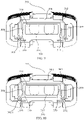

Classifications
-
- A—HUMAN NECESSITIES
- A24—TOBACCO; CIGARS; CIGARETTES; SIMULATED SMOKING DEVICES; SMOKERS' REQUISITES
- A24F—SMOKERS' REQUISITES; MATCH BOXES; SIMULATED SMOKING DEVICES
- A24F40/00—Electrically operated smoking devices; Component parts thereof; Manufacture thereof; Maintenance or testing thereof; Charging means specially adapted therefor
- A24F40/40—Constructional details, e.g. connection of cartridges and battery parts
-
- A—HUMAN NECESSITIES
- A24—TOBACCO; CIGARS; CIGARETTES; SIMULATED SMOKING DEVICES; SMOKERS' REQUISITES
- A24F—SMOKERS' REQUISITES; MATCH BOXES; SIMULATED SMOKING DEVICES
- A24F40/00—Electrically operated smoking devices; Component parts thereof; Manufacture thereof; Maintenance or testing thereof; Charging means specially adapted therefor
- A24F40/40—Constructional details, e.g. connection of cartridges and battery parts
- A24F40/48—Fluid transfer means, e.g. pumps
- A24F40/485—Valves; Apertures
-
- A—HUMAN NECESSITIES
- A24—TOBACCO; CIGARS; CIGARETTES; SIMULATED SMOKING DEVICES; SMOKERS' REQUISITES
- A24F—SMOKERS' REQUISITES; MATCH BOXES; SIMULATED SMOKING DEVICES
- A24F40/00—Electrically operated smoking devices; Component parts thereof; Manufacture thereof; Maintenance or testing thereof; Charging means specially adapted therefor
- A24F40/10—Devices using liquid inhalable precursors
-
- A—HUMAN NECESSITIES
- A24—TOBACCO; CIGARS; CIGARETTES; SIMULATED SMOKING DEVICES; SMOKERS' REQUISITES
- A24F—SMOKERS' REQUISITES; MATCH BOXES; SIMULATED SMOKING DEVICES
- A24F40/00—Electrically operated smoking devices; Component parts thereof; Manufacture thereof; Maintenance or testing thereof; Charging means specially adapted therefor
- A24F40/40—Constructional details, e.g. connection of cartridges and battery parts
- A24F40/42—Cartridges or containers for inhalable precursors
Definitions
- the present disclosure relates to the technical field of atomizing devices, and more particularly to an atomizer and an electronic atomizing device.
- the Electronic atomizing device in the related art is mainly composed of an atomizer and a power supply assembly.
- the atomizer generally includes a reservoir and an atomizing assembly.
- the reservoir is configured to store an aerosolizable medium.
- the atomizing assembly is configured to heat and atomize the aerosolizable medium, to form aerosol which can be taken in by the users.
- the power supply assembly is configured to provide energy for the atomizer.
- the aerosolizable medium stored in the reservoir is delivered to the atomizing assembly for atomization through a liquid aperture, and external air of outer atmosphere is delivered to the reservoir also through the liquid aperture to replenish an air pressure of the reservoir. Therefore, the external air tends to form bubbles in the liquid aperture in the process of entering the reservoir.
- a technical problem addressed by the present disclosure is to provide an atomizer and an electronic atomizing device, to solve the problem of bubbles tending to block the liquid path, which leads to an insufficient liquid supply.
- the atomizer comprises: a reservoir, configured to store liquid; a mounting base, including a housing and a baffle disposed on the housing, the baffle defining a liquid aperture and an air pressure balanced structure spaced apart from the liquid aperture; an atomizing core, disposed within the mounting base, and configured to heat and atomize the liquid.
- the air pressure balanced structure communicates the reservoir with outer atmosphere, and is configured to deliver external air into the reservoir, to balance an air pressure of the reservoir and the outer atmosphere.
- the second technical solution adopted by the present disclosure is to provide an electronic atomizing device.
- the electronic atomizing device includes an atomizer described above and a power supply assembly.
- the power supply assembly is configured to power the atomizer.
- the beneficial effect of the present disclosure is to provide an atomizer and an electronic atomizing device to distinguish with the related art.
- the atomizer includes: a reservoir, configured to store liquid; a mounting base, including a housing and a baffle disposed on the housing, the baffle defining a liquid aperture and an air pressure balanced structure spaced apart from the liquid aperture; an atomizing core, disposed within the mounting base, and configured to heat and atomize the liquid.
- the air pressure balanced structure communicates the reservoir with outer atmosphere, and is configured to deliver external air into the reservoir, to balance an air pressure of the reservoir and the outer atmosphere.
- a liquid path and an air supply path are independent from each other in the present disclosure, so as to avoid an occurrence of bubbles blocking the liquid path in the liquid aperture.
- a balance between the reservoir and the outer atmosphere may be achieved, and the problem that an insufficient liquid supply leads to a dry heating of the atomizing core is addressed.
- the structure is simple and easy to achieve.
- first”, “second”, and “third” in the embodiments of the present disclosure are only used for descriptive purposes, and cannot be understood as indicating or implying relative importance or implicitly indicating the number of indicated technical features. Thus, the features defined with “first”, “second”, and “third” may explicitly or implicitly include at least one of the features. In the description of the present application, "a plurality of' means at least two, e. g. , two, three, etc. , unless specifically defined otherwise.
- All directional indications (such as up, down, left, right, front, back) in the embodiments of the present disclosure are only used to account for relative positional relationships, motion conditions, etc., between components in a particular orientation (as shown in the drawings), if the particular orientation changed, correspondingly changes the directional indications.
- the terms "including” and “having” and any variations thereof are intended to cover non-exclusive inclusions. For example, a process, method, system, product, or device that includes a series of steps or units is not limited to the listed steps or units, but optionally includes unlisted steps or units, or optionally also includes other steps or units inherent to these processes, methods, products or equipment.
- FIG. 1 is a structural schematic figure of an embodiment of an electronic atomizing device provided by the present disclosure.
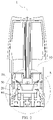
- FIG. 2 is a structural schematic figure of an embodiment of an atomizer of the electronic atomizing device provided by the present disclosure.
- FIG. 3 is a structural schematic figure of part A in FIG. 2 after enlargement.
- the electronic atomizing device 100 can be used for the atomization of tobacco oil.
- the electronic atomizing device 100 provided in the embodiment includes an atomizer 1 and a host 2.
- the atomizer 1 and the host 2 are detachably connected.
- the atomizer 1 comprises a reservoir 10, a mounting base 30, and an atomizing core 20.
- a power supply assembly is provided in the host 2.
- the atomizer 1 is plugged at one end port of the host 2, and is connected to the power supply assembly within the host 2, such that the atomizing core 20 in the atomizer 1 is powered by the power supply assembly. In the state where the atomizer 1 requires replacement, the atomizer 1 may be disassembled, and a new atomizer 1 is installed on the host 2, enabling reuse of the host 2.
- the electronic atomizing device 100 provided by the present disclosure includes the reservoir 10, the mounting base 30, the atomizing core 20, and a power supply assembly.
- the reservoir 10, the mounting base 30, the atomizing core 20 and the power assembly are formed of a single piece, and non-detachably connected.
- the electronic atomizing device 100 may further comprises other components of the electronic atomizing device in the prior art, such as, airflow sensor, bracket, and the like, specific structure and function of which are the same as or similar to those of the prior art, and are not described in detail herein.
- the atomizer 1 generally comprises the reservoir 10, the mounting base 30, the atomizing core 20, and a sealing element 50.
- the reservoir 10 is configured to store liquid (i.e. tobacco oil).
- the mounting base 30 includes a housing 303 and a baffle 304 disposed on the housing 303.
- the baffle 304 defines a liquid aperture 314 thereon, the baffle 304 further defines an air pressure balanced structure 305 spaced apart from the liquid aperture 314.
- the atomizing core 20 is disposed within the mounting base 30, and is configured to heat and atomize the liquid.
- the air pressure balanced structure 305 communicates the reservoir 10 with outer atmosphere, and is configured to deliver external air into the reservoir 10 to balance an air pressure of the reservoir 10 and the outer atmosphere, such that the liquid can reach the atomizing core 20.
- the sealing element 50 is provided between the baffle 304 and the atomizing core 20.
- the sealing element 50 is configured to prevent a liquid leakage of the air pressure balanced structure 305.
- the sealing element 50 may be a silicone sealing ring.
- the mounting base 30 includes an upper seat body 301 and a lower seat body 302, the upper seat body 301 and the lower seat body 302 are fixedly connected. Specifically, the upper seat body 301 and the lower seat body 302 may also be formed of a single piece, or connected by a snap firmware.
- the lower seat body 302 and the atomizing core 20 together form an atomizing chamber 40.
- the atomizing core 20 atomizes the tobacco oil and forms smoke in the atomizing chamber 40.
- the atomizing chamber 40 communicates with a smoke channel 316.
- the atomizing chamber 40 communicates with the air pressure balanced structure 305.
- a connection of the upper seat body 301 and the lower seat body 302 is provided with a sealing seat 312.
- the sealing seat 312 is used to seal the connection of the upper seat body 301 and the lower seat body 302, so as to prevent an occurrence of a liquid leakage.
- the lower seat body 302 is provided with an electrode lead, the electrode lead is electrically connected to the heating element of the atomizing core 20, so as to power the atomizing core 20.
- a side of the lower seat body 302 away from the atomizing core 20 defines an air intake 60.
- the air intake 60 connects the atomizing chamber 40 and the outer atmosphere.
- a position of the sealing seat 312 corresponding to the air intake 60 defined on the lower seat body 302 also defines a through-hole, for the external air to enter the atomizing chamber 40.
- the air input through the air intake 60 may be delivered to the air pressure balanced structure 305 through the atomizing chamber 40, and then input into the reservoir 10, to balance the air pressure of the reservoir 10 and the outer atmosphere.
- the upper seat body 301 includes the housing 303 described above and the baffle 304 disposed on the housing 303.
- the baffle 304 defines the liquid aperture 314.
- the liquid aperture 314 communicates with the reservoir 10, and may allow the liquid within the reservoir 10 to be delivered to the atomizing core 20.
- the baffle 304 may divide the space within the housing 303 into a liquid intake chamber 313 and an access chamber 318.
- the liquid intake chamber 313 and the access chamber 318 communicate with each other through the liquid aperture 314 and the air pressure balanced structure 305 defined on baffle 304.
- the housing 303 defines the smoke channel 316, the smoke channel 316 and the liquid intake chamber 313 are on the same side.
- the smoke channel 316 is configured to direct the smoke into oral cavity of user.
- the baffle 304 may be attached to an end of the housing 303 toward the reservoir 10, such that baffle 304 need not to form the liquid intake chamber 313 together with the housing 303.
- the baffle 304 is attached to an end of the housing 303 away from the reservoir 10, such that baffle 304 need not to form the access cavity 318 together with the housing 303.
- the present disclosure is not intended to limit the specific configuration of the mounting base 30.
- the following mating relationship of the mounting base 30, the atomizing core 20 and the sealing element 50 is applicable to all kinds of deformed configurations of the mounting base 30. Only if the liquid aperture 314 communicates with the reservoir 10, for example, the reservoir 10 may be a flexible liquid storage pot, a liquid storage sphere, or the like, which is connected to the baffle 304, and the reservoir 10 communicates with liquid aperture 314.
- the baffle 304 may be a plate with the liquid aperture 314 defined in the middle and the air pressure balanced structure 305 spaced around the periphery of the liquid aperture 314.
- the baffle 304 is a plate with a plurality of liquid apertures 314 in the middle, and the air pressure balanced structure 305 spaced around the periphery of at least one of the liquid aperture 314.
- the present disclosure does not limit the specific configuration of the baffle 304, only if the liquid aperture 314 defined on the baffle 304 communicates with the reservoir 10, and the air pressure balanced structure 305 defined on the baffle 304 may communicate the reservoir 10 with the outer atmosphere.
- the atomizing core 20 atomizes the tobacco oil.
- the external air enters the atomizing chamber 40 through the air intake 60 and carries the smoke within the atomizing chamber 40 to the user's mouth through the smoke channel 316.
- the air within the atomizing chamber 40 may be delivered to the reservoir 10 through air pressure balanced structure 305, to balance the air pressure of the reservoir 10, the atomizing chamber 40, and the outer atmosphere, such that the tobacco oil within the reservoir 10 may be smoothly delivered to the atomizing core 20 through the liquid aperture 314, avoiding an occurrence of dry heating of the atomizing core 20.
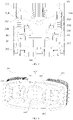
- FIG. 4 is a top view of an upper seat body in a mounting base provided by the present disclosure.
- FIG. 5 is a bottom view of a first embodiment of the upper seat body in the mounting base provided by the present disclosure.
- FIG. 6 is a bottom view of a second embodiment of the upper seat body in the mounting base provided by the present disclosure.
- FIG. 7 is a bottom view of a third embodiment of the upper seat body in the mounting base provided by the present disclosure.
- FIG. 8 is a bottom view of a fourth embodiment of the upper seat body in the mounting base provided by the present disclosure.
- FIG. 9 is a bottom view of the fifth embodiment of the upper seat body in the mounting base provided by the present disclosure.
- FIG. 10 is a bottom view of the sixth embodiment of the upper seat body of the mounting base provided by the present disclosure.
- FIG. 11 is a bottom view of a seventh embodiment of the upper seat body in the mounting base provided by the present disclosure.
- FIG. 12 is a bottom view of an eighth embodiment of the upper seat body in the mounting base provided by the present disclosure.
- the baffle 304 of the upper seat body 301 defines the air pressure balanced structure 305.
- the air pressure balanced structure 305 includes a gas guiding port structure 307 and a gas guiding groove structure 306.
- the gas guiding port structure 307 goes through the baffle 304, and is spaced apart from the liquid aperture 314.
- the gas guiding port structure 307 communicates the liquid intake chamber 313 with the access chamber 318.
- the gas guiding groove structure 306 is defined on a side of baffle 304 away from the liquid intake chamber 313.
- One end of the gas guiding groove structure 306 communicates with an end of the gas guiding port structure 307 away from liquid intake chamber 313, the other end of the gas guiding groove structure 306 extends in a direction away from the gas guiding port structure 307, and then communicates with the atomizing chamber 40.
- An inner surface of the housing 303 defines a connecting slot 3031.
- the connecting slot 3031 communicates the gas guiding groove structure 306 and the atomizing chamber 40.
- the other end of the gas guiding groove structure 306 may also communicates with outer atmosphere directly.
- a cross section of the gas guiding port structure 307 may be at least one of circular, oval, rectangular, semi-circular, etc., or other shapes which facilitates gas guiding.
- a number of the gas guiding groove structure 306 communicating with the gas guiding port structure 307 may be one or more, and the number of gas guiding groove structure 306 may be designed according to the actual requirements.
- the silicone sealing ring is provided between the upper seat body 301 and the atomizing core 20. The silicone sealing ring abuts against the surface of the baffle 304 away from the reservoir 10, such that the gas guiding port structure 307 and the gas guiding groove structure 306 are configured to form a first gas guiding channel between the baffle 304 and the silicone sealing ring.
- a size of the gas guiding groove structure 306 ranges from 0.1 mm to 0.8 mm, which may be a depth of the gas guiding groove structure 306 or a width of the gas guiding groove structure 306.
- a size of the cross-section of the gas guiding port structure 307 ranges from 0.1 mm to 1 mm, which may be a length, a width, or a diameter of the cross-section of the gas guiding port structure 307.
- the air pressure balanced structure 305 includes the gas guiding port structure 307 and the gas guiding groove structure 306.
- the gas guiding port structure 307 is defined on the baffle 304, and is spaced apart from the liquid aperture 314. Specifically, a number of the gas guiding port structure 307 may be one or more.
- the gas guiding port structure 307 includes a first gas guiding port 308 and a second gas guiding port 309.
- the gas guiding groove structure 306 includes a first gas guiding groove 310 and a second gas guiding groove 311.
- the first gas guiding port 308 and the second gas guiding port 309 are arranged symmetrically on both sides of the liquid aperture 314.
- the first gas guiding groove 310 communicates with an end of the first gas guiding port 308 away from the liquid intake chamber 313.
- the second gas guiding groove 311 communicates with an end of the second gas guiding port 309 away from the liquid intake chamber 313.
- the first gas guiding groove 310 extends along an inner wall of the access chamber 318 in a direction away from the first gas guiding port 308.
- the second gas guiding groove 311 extends along the inner wall of the access chamber 318 in a direction away from the second gas guiding port 309. Therefore, an end of the first gas guiding groove 310 away from the first gas guiding port 308 communicates with the atomizing chamber 40, an end of the second gas guiding groove 311 away from the second gas guiding port 309 communicates with the atomizing chamber 40.
- the first gas guiding port 308 communicates with the first gas guiding groove 310
- the second gas guiding port 309 communicates with the second gas guiding groove 311.
- the end of the first gas guiding groove 310 away from the first gas guiding port 308 and the end of the second gas guiding groove 311 away from the second gas guiding port 309 extend along the inner wall of the access chamber 318 in a direction away from the baffle 304.
- the first gas guiding groove 310 and the second gas guiding groove 311 may be arranged symmetrically or asymmetrically. As long as it is convenient for the air in the atomizing chamber 40 to enter the reservoir 10 through the first and second gas guiding grooves 310, 311 and the first and second gas guiding ports 308, 309 connected thereto.
- the end of the first gas guiding groove 310 away from the first gas guiding port 308 and the end of the second gas guiding groove 311 away from the second gas guiding port 309 extend through the housing 303 to communicates with the outer atmosphere directly.
- the end of the first gas guiding groove 310 away from the first gas guiding port 308 communicates with the atomizing chamber 40, and then communicates with the outer atmosphere through the air intake 60 defined in the bottom of the atomizing chamber 40, the end of the second gas guiding groove 311 away from the second gas guiding port 309 extends through the housing 303 and communicates with the outer atmosphere directly.
- the gas guiding groove structure 306 further includes a third gas guiding groove 319 and a fourth gas guiding groove 320.
- One end of the third gas guiding groove 319 communicates with the first gas guiding port 308, the other end of the third gas guiding groove 319 communicates with the liquid aperture 314.
- One end of the fourth gas guiding groove 320 communicates with the second gas guiding port 309, and the other end of the fourth gas guiding groove 320 communicates with the liquid aperture 314.
- the third gas guiding groove 319 may deliver the air delivered in the first gas guiding groove 310 through the liquid aperture 314.
- the fourth gas guiding groove 320 may deliver the air delivered in the second gas guiding groove 311 through the liquid aperture 314.
- one end of the first gas guiding groove 310 communicates with the atomizing chamber 40 or the outer atmosphere, and the other end of the first gas guiding groove 310 communicates with the first gas guiding port 308.
- An end of the third gas guiding groove 319 communicates with the atomizing chamber 40 or the outer atmosphere directly, and the other end of the third gas guiding groove 319 communicates with the liquid aperture 314.
- One end of the second gas guiding groove 311 communicates with the atomizing chamber 40 or the outer atmosphere, and the other end of the second gas guiding groove 311 communicates with the second gas guiding port 309.
- One end of the fourth gas guiding port 320 communicates with the atomizing chamber 40 or the outer atmosphere directly, and the other end of the fourth gas guiding port 320 communicates with the liquid aperture 314.
- the air pressure balanced structure 305 includes the gas guiding port structure 307 and the gas guiding groove structure 306 connected to the gas guiding port structure 307.
- the gas guiding groove structure 306 comprises a first gas guiding groove 310 and a second gas guiding groove 311.
- the gas guiding port structure 307 comprises a first gas guiding port 308 and a second gas guiding port 309.
- the first gas guiding port 308 and the second gas guiding port 309 are both disposed on the baffle 304 and spaced apart from the liquid aperture 314.
- the first gas guiding port 308 and the second gas guiding port 309 are symmetrically disposed on both sides of liquid aperture 314.
- the first gas guiding groove 310 and the second gas guiding groove 311 are symmetrically disposed on both sides of the liquid aperture 314.
- the first gas guiding groove 310 and the second gas guiding groove 311 are disposed on the side of the baffle 304 away from the liquid intake chamber 313.
- the first gas guiding groove 310 communicates with an end of the first gas guiding port 308 away from the liquid intake chamber 313, both two ends of the first gas guiding groove 310 extend along the inner wall of the access chamber 318 in a direction away from the first gas guiding port 308, and then both two ends of the first gas guiding groove 310 communicate with the atomizing chamber 40.
- the second gas guiding groove 311 communicates with an end of the second gas guiding port 309 away from the liquid intake chamber 313, both two ends of the second gas guiding groove 310 extend along the inner wall of the access chamber 318 in a direction away from the second gas guiding port 309, and then both two ends of the second gas guiding groove 311 communicate with the atomizing chamber 40.
- the end of the first gas guiding groove 310 away from the first gas guiding port 308 and the end of the second gas guiding groove 311 away from the second gas guiding port 309 may extend through the housing 303 to communicate with the outer atmosphere directly.
- At least one of the end of the first gas guiding groove 310 away from the first gas guiding port 308 and the end of the second gas guiding groove 311 away from the second gas guiding port 309 may extend through the housing 303 to communicate with the outer atmosphere directly, and the others communicate with the atomizing chamber 40, and then communicates with the outer atmosphere through the air intake 60 defined in the bottom of the atomizing chamber 40.
- At least one of the end of the first gas guiding groove 310 away from the first gas guiding port 308 and the end of the second gas guiding groove 311 away from the second gas guiding port 309 communicates with the atomizing chamber 40, and then communicates with the outer atmosphere through the air intake 60 defined in the bottom of the atomizing chamber 40, and the others may extend through the housing 303 to communicate with the outer atmosphere directly.
- the gas guiding groove structure 306 further includes a third gas guiding groove 319 and a fourth gas guiding groove 320.
- One end of the third gas guiding groove 319 communicates with the first gas guiding port 308, and the other end of the third gas guiding groove 319 communicates with the liquid aperture 314.
- One end of the fourth gas guiding groove 320 communicates with the second gas guiding port 309, and the other end of the fourth gas guiding groove 320 communicates with the liquid aperture 314.
- the third gas guiding groove 319 may deliver the air delivered in the first gas guiding groove 310 through the liquid aperture 314.
- the fourth gas guiding groove 320 may deliver the air delivered in the second gas guiding groove 311 through the liquid aperture 314.
- one end of the first gas guiding groove 310 communicates with the atomizing chamber 40 or the outer atmosphere, and the other end of the first gas guiding groove 310 communicates with the first gas guiding port 308.
- One end of the third gas guiding groove 319 communicates with the atomizing chamber 40 or the outer atmosphere directly, and the other end of the third gas guiding groove 319 communicates with the liquid aperture 314.
- One end of the second gas guiding groove 311 communicates with the atomizing chamber 40 or the outer atmosphere, and the other end of the second gas guiding groove 311 communicates with the second gas guiding port 309.
- One end of the fourth gas guiding port 320 communicates with the atomizing chamber 40 or the outer atmosphere directly, and the other end of the fourth gas guiding port 320 communicates with the liquid aperture 314.
- the air pressure balanced structure 305 includes a gas guiding port structure 307 and a gas guiding groove structure 306 connected to the gas guiding port structure 307.
- the gas guiding groove structure 306 comprises a first gas guiding groove 310, a second gas guiding groove 311 and a connecting groove 315.
- the gas guiding port structure 307 comprises a first gas guiding port 308 and a second gas guiding port 309.
- the first gas guiding port 308 and the second gas guiding port 309 are both disposed on the baffle 304 and spaced apart from the liquid aperture 314.
- the first gas guiding port 308 and the second gas guiding port 309 are symmetrically disposed on both sides of liquid aperture 314.
- the first gas guiding groove 310 and the second gas guiding groove 311 are disposed on the side of the baffle 304 away from the liquid intake chamber 313.
- the first gas guiding groove 310 communicates with an end of the first gas guiding port 308 away from the liquid intake chamber 313, both two ends of the first gas guiding groove 310 extend along the inner wall of the access chamber 318 in a direction away from the first gas guiding port 308, and then both two ends of the first gas guiding groove 310 communicate with the atomizing chamber 40.
- the second gas guiding groove 311 communicates with an end of the second gas guiding port 309 away from the liquid intake chamber 313, both two ends of the second gas guiding groove 310 extend along the inner wall of the access chamber 318 in a direction away from the second gas guiding port 309, and then both two ends of the second gas guiding groove 311 communicate with the atomizing chamber 40.
- the second gas guiding groove 311 and the first gas guiding groove 310 are connected by the connecting groove 315.
- the connecting groove 315 may conduct the air delivered in the first gas guiding groove 310 to the second gas guiding port 309, and may also conduct the air delivered in the second gas guiding groove 311 to the first gas guiding port 308, which is beneficial to balance the air pressure of the reservoir 10 and the outer atmosphere.
- the end of the first gas guiding groove 310 away from the first gas guiding port 308 and the end of the second gas guiding groove 311 away from the second gas guiding port 309 may extend through the housing 303 to communicate with the outer atmosphere directly.
- At least one of the end of the first gas guiding groove 310 away from the first gas guiding port 308 and the end of the second gas guiding groove 311 away from the second gas guiding port 309 may extend through the housing 303 to communicate with the outer atmosphere directly, and the others communicate with the atomizing chamber 40, and then communicates with the outer atmosphere through the air intake 60 defined in the bottom of the atomizing chamber 40.
- At least one of the end of the first gas guiding groove 310 away from the first gas guiding port 308 and the end of the second gas guiding groove 311 away from the second gas guiding port 309 communicates with the atomizing chamber 40, and then communicates with the outer atmosphere through the air intake 60 defined in the bottom of the atomizing chamber 40, and the others may extend through the housing 303 to communicate with the outer atmosphere directly.
- the gas guiding groove structure 306 further includes a third gas guiding groove 319 and a fourth gas guiding groove 320.
- One end of the third gas guiding groove 319 communicates with the first gas guiding port 308, and the other end of the third gas guiding groove 319 communicates with the liquid aperture 314.
- One end of the fourth gas guiding groove 320 communicates with the second gas guiding port 309, and the other end of the fourth gas guiding groove 320 communicates with the liquid aperture 314.
- the third gas guiding groove 319 may deliver the air delivered in the first gas guiding groove 310 through the liquid aperture 314.
- the fourth gas guiding groove 320 may deliver the air delivered in the second gas guiding groove 311 through the liquid aperture 314.
- one end of the first gas guiding groove 310 communicates with the atomizing chamber 40 or the outer atmosphere, and the other end of the first gas guiding groove 310 communicates with the first gas guiding port 308.
- One end of the third gas guiding groove 319 communicates with the atomizing chamber 40 or the outer atmosphere directly, and the other end of the third gas guiding groove 319 communicates with the liquid aperture 314.
- One end of the second gas guiding groove 311 communicates with the atomizing chamber 40 or the outer atmosphere, and the other end of the second gas guiding groove 311 communicates with the second gas guiding port 309.
- One end of the fourth gas guiding port 320 communicates with the atomizing chamber 40 or the outer atmosphere directly, and the other end of the fourth gas guiding port 320 communicates with the liquid aperture 314.
- the air pressure balanced structure 305 includes a gas guiding port structure 307 and a gas guiding groove structure 306 connected to the gas guiding port structure 307.
- the gas guiding groove structure 306 comprises a first gas guiding groove 310 and a second gas guiding groove 311.
- the gas guiding port structure 307 comprises a first gas guiding port 308 and a second gas guiding port 309.
- the first gas guiding port 308 and the second gas guiding port 309 are both disposed on the baffle 304 and spaced apart from the liquid aperture 314.
- the first gas guiding port 308 and the second gas guiding port 309 are symmetrically disposed on both sides of liquid aperture 314.
- the first gas guiding groove 310 and the second gas guiding groove 311 are symmetrically disposed on both sides of the liquid aperture 314.
- the first gas guiding groove 310 and the second gas guiding groove 311 are disposed on the side of the baffle 304 away from the liquid intake chamber 313.
- One end of the first gas guiding groove 310 communicates with an end of the first gas guiding port 308 away from the liquid intake chamber 313, the other end of the first gas guiding groove 310 extend along the baffle 304 to a position near the second gas guiding port 309, and then extend along the inner wall of the access chamber 318 to communicate with the atomizing chamber 40.
- One end of the second gas guiding groove 311 communicates with an end of the second gas guiding port 309 away from the liquid intake chamber 313, the other end of the second gas guiding groove 311 extend along the baffle 304 to a position near the first gas guiding port 308, and then extend along the inner wall of the access chamber 318 to communicate with the atomizing chamber 40, and finally communicates with the outer atmosphere through the air intake 60 in the bottom of the atomizing chamber 40.
- the end of the first gas guiding groove 310 away from the first gas guiding port 308 and the end of the second gas guiding groove 311 away from the second gas guiding port 309 extend through the housing 303 to communicate with the outer atmosphere directly.
- one of the end of the first gas guiding groove 310 away from the first gas guiding port 308 and the end of the second gas guiding groove 311 away from the second gas guiding port 309 may extend through the housing 303 to communicate with the outer atmosphere directly, and the other communicate with the atomizing chamber 40, and then communicates with the outer atmosphere through the air intake 60 defined in the bottom of the atomizing chamber 40.
- the gas guiding groove structure 306 further includes a third gas guiding groove 319 and a fourth gas guiding groove 320.
- One end of the third gas guiding groove 319 communicates with the first gas guiding port 308, and the other end of the third gas guiding groove 319 communicates with the liquid aperture 314.
- One end of the fourth gas guiding groove 320 communicates with the second gas guiding port 309, and the other end of the fourth gas guiding groove 320 communicates with the liquid aperture 314.
- the third gas guiding groove 319 may deliver the air delivered in the first gas guiding groove 310 through the liquid aperture 314.
- the fourth gas guiding groove 320 may deliver the air delivered in the second gas guiding groove 311 through the liquid aperture 314.
- one end of the first gas guiding groove 310 communicates with the atomizing chamber 40 or the outer atmosphere, and the other end of the first gas guiding groove 310 communicates with the first gas guiding port 308.
- One end of the third gas guiding groove 319 communicates with the atomizing chamber 40 or the outer atmosphere directly, and the other end of the third gas guiding groove 319 communicates with the liquid aperture 314.
- One end of the second gas guiding groove 311 communicates with the atomizing chamber 40 or the outer atmosphere, and the other end of the second gas guiding groove 311 communicates with the second gas guiding port 309.
- One end of the fourth gas guiding port 320 communicates with the atomizing chamber 40 or the outer atmosphere directly, and the other end of the fourth gas guiding port 320 communicates with the liquid aperture 314.
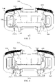
- the liquid within the reservoir 10 flows to the atomizing core 20 through the liquid aperture 314.
- the air pressure balanced structure 305 delivers the external air into the reservoir 10, such that the air pressure of the reservoir 10 is balanced with the air pressure of the outer atmosphere.
- the atomizing core 20 atomizes the tobacco oil
- the air pressure in the atomizing chamber 40 is greater than the air pressure of the reservoir 10
- the atomizing chamber 40 communicates with the outer atmosphere
- the external air of the outer atmosphere enters the atomizing chamber 40 through the air intake 60
- the air in the atomizing chamber 40 is forced to enter the first gas guiding groove 310 and second gas guiding groove 311 due to a pressure difference
- the air in the first gas guiding groove 310 enters the reservoir 10 through the first gas guiding port 308, the air in the second gas guiding groove 311 enters the reservoir 10 through the second gas guiding port 309.
- the air pressure of the reservoir 10 and the atomizing chamber 40 are balanced, and then the tobacco oil within the reservoir 10 enters the atomizing core 20 through the liquid aperture 314.
- the tobacco oil within the reservoir 10 may be smoothly delivered to the atomizing core 20 through the liquid aperture 314, avoiding an occurrence of dry heating of the atomizing core 20.
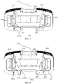
- the atomizing core 20 atomizes the tobacco oil
- the air pressure in the atomizing chamber 40 is greater than the air pressure of the reservoir 10
- the external air of outer atmosphere is forced to enter the first gas guiding groove 310 and second gas guiding groove 311 due to a pressure difference
- the air in the first gas guiding groove 310 enters the reservoir 10 through the first gas guiding port 308
- the air in the second gas guiding groove 311 enters the reservoir 10 through the second gas guiding port 309.
- the air pressure of the reservoir 10 and the atomizing chamber 40 are balanced, and then the tobacco oil within the reservoir 10 enters the atomizing core 20 through the liquid aperture 314.
- the tobacco oil within the reservoir 10 may be smoothly delivered to the atomizing core 20 through the liquid aperture 314, avoiding an occurrence of dry heating of the atomizing core 20.
- the atomizing core 20 atomizes the tobacco oil
- the air pressure in the atomizing chamber 40 is greater than the air pressure of the reservoir 10
- the atomizing chamber 40 communicates with the outer atmosphere
- the external air of outer atmosphere enters the atomizing chamber 40 through the air intake 60
- the air in the atomizing chamber 40 is forced to enter the first gas guiding groove 310 and second gas guiding groove 311 due to a pressure difference
- the air in the first gas guiding groove 310 enters the reservoir 10 through the first gas guiding port 308.
- the third gas guiding groove 319 deliver the air which has not been delivered in the first gas groove 310 to the reservoir 10 through liquid aperture 314.
- the fourth gas guiding groove 320 deliver the air which has not been delivered in the second gas groove 311 to the reservoir 10 through liquid aperture 314.
- the air pressure of the reservoir 10 and the atomizing chamber 40 are balanced, and then the tobacco oil within the reservoir 10 enters the atomizing core 20 through the liquid aperture 314.
- the tobacco oil within the reservoir 10 may be smoothly delivered to the atomizing core 20 through the liquid aperture 314, avoiding an occurrence of dry heating of the atomizing core 20.
- the embodiment provides an atomizer and an electronic atomizing device.
- the atomizer includes: a reservoir, configured to store liquid; a mounting base, including a housing and a baffle disposed on the housing, the baffle defining a liquid aperture and an air pressure balanced structure spaced apart from the liquid aperture; an atomizing core, disposed within the mounting base, and configured to heat and atomize the liquid.
- the air pressure balanced structure communicates the reservoir with outer atmosphere, and is configured to deliver external air into the reservoir, to balance an air pressure of the reservoir and the outer atmosphere.
Landscapes
- Disinfection, Sterilisation Or Deodorisation Of Air (AREA)
- Nozzles (AREA)
- Special Spraying Apparatus (AREA)
- Electrostatic Spraying Apparatus (AREA)
Abstract
Description
- The present disclosure relates to the technical field of atomizing devices, and more particularly to an atomizer and an electronic atomizing device.
- Electronic atomizing device in the related art is mainly composed of an atomizer and a power supply assembly. The atomizer generally includes a reservoir and an atomizing assembly. The reservoir is configured to store an aerosolizable medium. The atomizing assembly is configured to heat and atomize the aerosolizable medium, to form aerosol which can be taken in by the users. The power supply assembly is configured to provide energy for the atomizer.
- In the related art, the aerosolizable medium stored in the reservoir is delivered to the atomizing assembly for atomization through a liquid aperture, and external air of outer atmosphere is delivered to the reservoir also through the liquid aperture to replenish an air pressure of the reservoir. Therefore, the external air tends to form bubbles in the liquid aperture in the process of entering the reservoir. In the state where the atomizer atomizes the aerosolizable medium, bubbles tend to block a narrowest part of a liquid path in the process of entering the reservoir through a liquid aperture, which leads to an insufficient liquid supply to the atomizing assembly, as a result, the aerosolizable medium cannot be replenished to the atomizing assembly, which causing dry heating and overheating of the atomizing assembly, finally the atomizing assembly is damaged due to the insufficient liquid supply, and burnt taste and harmful substances is produced.
- A technical problem addressed by the present disclosure is to provide an atomizer and an electronic atomizing device, to solve the problem of bubbles tending to block the liquid path, which leads to an insufficient liquid supply.
- To solve the above technical problem, the first technical solution adopted by the present disclosure is to provide an atomizer. The atomizer comprises: a reservoir, configured to store liquid; a mounting base, including a housing and a baffle disposed on the housing, the baffle defining a liquid aperture and an air pressure balanced structure spaced apart from the liquid aperture; an atomizing core, disposed within the mounting base, and configured to heat and atomize the liquid. Wherein the air pressure balanced structure communicates the reservoir with outer atmosphere, and is configured to deliver external air into the reservoir, to balance an air pressure of the reservoir and the outer atmosphere.
- To solve the above technical problem, the second technical solution adopted by the present disclosure is to provide an electronic atomizing device. The electronic atomizing device includes an atomizer described above and a power supply assembly. The power supply assembly is configured to power the atomizer.
- The beneficial effect of the present disclosure is to provide an atomizer and an electronic atomizing device to distinguish with the related art. The atomizer includes: a reservoir, configured to store liquid; a mounting base, including a housing and a baffle disposed on the housing, the baffle defining a liquid aperture and an air pressure balanced structure spaced apart from the liquid aperture; an atomizing core, disposed within the mounting base, and configured to heat and atomize the liquid. The air pressure balanced structure communicates the reservoir with outer atmosphere, and is configured to deliver external air into the reservoir, to balance an air pressure of the reservoir and the outer atmosphere. By defining the air pressure balanced structure spaced apart from the liquid aperture on the baffle, a liquid path and an air supply path are independent from each other in the present disclosure, so as to avoid an occurrence of bubbles blocking the liquid path in the liquid aperture. By defining the air pressure balanced structure, a balance between the reservoir and the outer atmosphere may be achieved, and the problem that an insufficient liquid supply leads to a dry heating of the atomizing core is addressed. The structure is simple and easy to achieve.
- In order to illustrate the technical solutions in the embodiments of the present disclosure or the prior art more clearly, the following will briefly introduce the figures needed to be used in the description of the embodiments or the prior art. Obviously, the drawings in the following description are only some embodiments of the present disclosure. Those skilled in the art may derive other figures from these figures without paying any creative work.
-
FIG. 1 is a structural schematic figure of an embodiment of an electronic atomizing device provided by the present disclosure. -
FIG. 2 is a structural schematic figure of an embodiment of an atomizer of the electronic atomizing device provided by the present disclosure. -
FIG. 3 is a structural schematic figure of part A inFIG. 2 after enlargement. -
FIG. 4 is a top view of an upper seat body in a mounting base provided by the present disclosure. -
FIG. 5 is a bottom view of a first embodiment of the upper seat body in the mounting base provided by the present disclosure. -
FIG. 6 is a bottom view of a second embodiment of the upper seat body in the mounting base provided by the present disclosure. -
FIG. 7 is a bottom view of a third embodiment of the upper seat body in the mounting base provided by the present disclosure. -
FIG. 8 is a bottom view of a fourth embodiment of the upper seat body in the mounting base provided by the present disclosure. -
FIG. 9 is a bottom view of the fifth embodiment of the upper seat body in the mounting base provided by the present disclosure. -
FIG. 10 is a bottom view of the sixth embodiment of the upper seat body of the mounting base provided by the present disclosure. -
FIG. 11 is a bottom view of a seventh embodiment of the upper seat body in the mounting base provided by the present disclosure. -
FIG. 12 is a bottom view of an eighth embodiment of the upper seat body in the mounting base provided by the present disclosure. - The technical solutions in the embodiments of the present disclosure will be described clearly and completely with reference to the figures in the embodiments of the present disclosure. Obviously, the described embodiments are only a part of the embodiments of the present disclosure, rather than all the embodiments. Based on the embodiments of the present disclosure, all other embodiments obtained by those skilled in the art without any creative work are within the scope of the present disclosure.
- The terms "first", "second", and "third" in the embodiments of the present disclosure are only used for descriptive purposes, and cannot be understood as indicating or implying relative importance or implicitly indicating the number of indicated technical features. Thus, the features defined with "first", "second", and "third" may explicitly or implicitly include at least one of the features. In the description of the present application, "a plurality of' means at least two, e. g. , two, three, etc. , unless specifically defined otherwise. All directional indications (such as up, down, left, right, front, back) in the embodiments of the present disclosure are only used to account for relative positional relationships, motion conditions, etc., between components in a particular orientation (as shown in the drawings), if the particular orientation changed, correspondingly changes the directional indications. In addition, the terms "including" and "having" and any variations thereof are intended to cover non-exclusive inclusions. For example, a process, method, system, product, or device that includes a series of steps or units is not limited to the listed steps or units, but optionally includes unlisted steps or units, or optionally also includes other steps or units inherent to these processes, methods, products or equipment.
- Mentioning "embodiments" herein means that a specific feature, structure, or characteristic described in conjunction with the embodiments may be included in at least one embodiment of the present disclosure. The appearances of the phrase in various places in the specification are not necessarily all referring to the same embodiment, nor are separate or alternative embodiments mutually exclusive of other embodiments. It is explicitly and implicitly understood by those skilled in the art that the embodiments described herein may be combined with other embodiments.
- Please referring to
FIG. 1 ,FIG. 2 , andFIG. 3 ,FIG. 1 is a structural schematic figure of an embodiment of an electronic atomizing device provided by the present disclosure.FIG. 2 is a structural schematic figure of an embodiment of an atomizer of the electronic atomizing device provided by the present disclosure.FIG. 3 is a structural schematic figure of part A inFIG. 2 after enlargement. The electronic atomizingdevice 100 can be used for the atomization of tobacco oil. The electronic atomizingdevice 100 provided in the embodiment includes anatomizer 1 and ahost 2. Theatomizer 1 and thehost 2 are detachably connected. Theatomizer 1 comprises areservoir 10, amounting base 30, and an atomizingcore 20. A power supply assembly is provided in thehost 2. Theatomizer 1 is plugged at one end port of thehost 2, and is connected to the power supply assembly within thehost 2, such that the atomizingcore 20 in theatomizer 1 is powered by the power supply assembly. In the state where theatomizer 1 requires replacement, theatomizer 1 may be disassembled, and anew atomizer 1 is installed on thehost 2, enabling reuse of thehost 2. - In some embodiments, the electronic atomizing
device 100 provided by the present disclosure includes thereservoir 10, themounting base 30, the atomizingcore 20, and a power supply assembly. Thereservoir 10, the mountingbase 30, theatomizing core 20 and the power assembly are formed of a single piece, and non-detachably connected. - Of course, the
electronic atomizing device 100 may further comprises other components of the electronic atomizing device in the prior art, such as, airflow sensor, bracket, and the like, specific structure and function of which are the same as or similar to those of the prior art, and are not described in detail herein. - As shown in
FIG. 2 , theatomizer 1 generally comprises thereservoir 10, the mountingbase 30, theatomizing core 20, and a sealingelement 50. Thereservoir 10 is configured to store liquid (i.e. tobacco oil). As shown inFIG. 3 , the mountingbase 30 includes ahousing 303 and abaffle 304 disposed on thehousing 303. Thebaffle 304 defines aliquid aperture 314 thereon, thebaffle 304 further defines an air pressurebalanced structure 305 spaced apart from theliquid aperture 314. Theatomizing core 20 is disposed within the mountingbase 30, and is configured to heat and atomize the liquid. The air pressurebalanced structure 305 communicates thereservoir 10 with outer atmosphere, and is configured to deliver external air into thereservoir 10 to balance an air pressure of thereservoir 10 and the outer atmosphere, such that the liquid can reach theatomizing core 20. The sealingelement 50 is provided between thebaffle 304 and theatomizing core 20. The sealingelement 50 is configured to prevent a liquid leakage of the air pressurebalanced structure 305. The sealingelement 50 may be a silicone sealing ring. - The mounting
base 30 includes anupper seat body 301 and alower seat body 302, theupper seat body 301 and thelower seat body 302 are fixedly connected. Specifically, theupper seat body 301 and thelower seat body 302 may also be formed of a single piece, or connected by a snap firmware. Thelower seat body 302 and theatomizing core 20 together form anatomizing chamber 40. Theatomizing core 20 atomizes the tobacco oil and forms smoke in theatomizing chamber 40. Theatomizing chamber 40 communicates with asmoke channel 316. Theatomizing chamber 40 communicates with the air pressurebalanced structure 305. A connection of theupper seat body 301 and thelower seat body 302 is provided with a sealingseat 312. The sealingseat 312 is used to seal the connection of theupper seat body 301 and thelower seat body 302, so as to prevent an occurrence of a liquid leakage. - The
lower seat body 302 is provided with an electrode lead, the electrode lead is electrically connected to the heating element of theatomizing core 20, so as to power theatomizing core 20. A side of thelower seat body 302 away from theatomizing core 20 defines anair intake 60. Theair intake 60 connects theatomizing chamber 40 and the outer atmosphere. A position of the sealingseat 312 corresponding to theair intake 60 defined on thelower seat body 302 also defines a through-hole, for the external air to enter theatomizing chamber 40. The air input through theair intake 60 may be delivered to the air pressurebalanced structure 305 through theatomizing chamber 40, and then input into thereservoir 10, to balance the air pressure of thereservoir 10 and the outer atmosphere. - Specifically, the
upper seat body 301 includes thehousing 303 described above and thebaffle 304 disposed on thehousing 303. Thebaffle 304 defines theliquid aperture 314. Theliquid aperture 314 communicates with thereservoir 10, and may allow the liquid within thereservoir 10 to be delivered to theatomizing core 20. In the embodiment, thebaffle 304 may divide the space within thehousing 303 into aliquid intake chamber 313 and anaccess chamber 318. Theliquid intake chamber 313 and theaccess chamber 318 communicate with each other through theliquid aperture 314 and the air pressurebalanced structure 305 defined onbaffle 304. Thehousing 303 defines thesmoke channel 316, thesmoke channel 316 and theliquid intake chamber 313 are on the same side. Thesmoke channel 316 is configured to direct the smoke into oral cavity of user. - In some embodiments, the
baffle 304 may be attached to an end of thehousing 303 toward thereservoir 10, such thatbaffle 304 need not to form theliquid intake chamber 313 together with thehousing 303. Or thebaffle 304 is attached to an end of thehousing 303 away from thereservoir 10, such thatbaffle 304 need not to form theaccess cavity 318 together with thehousing 303. The present disclosure is not intended to limit the specific configuration of the mountingbase 30. The following mating relationship of the mountingbase 30, theatomizing core 20 and the sealingelement 50 is applicable to all kinds of deformed configurations of the mountingbase 30. Only if theliquid aperture 314 communicates with thereservoir 10, for example, thereservoir 10 may be a flexible liquid storage pot, a liquid storage sphere, or the like, which is connected to thebaffle 304, and thereservoir 10 communicates withliquid aperture 314. - The
baffle 304 may be a plate with theliquid aperture 314 defined in the middle and the air pressurebalanced structure 305 spaced around the periphery of theliquid aperture 314. In some embodiments, thebaffle 304 is a plate with a plurality ofliquid apertures 314 in the middle, and the air pressurebalanced structure 305 spaced around the periphery of at least one of theliquid aperture 314. The present disclosure does not limit the specific configuration of thebaffle 304, only if theliquid aperture 314 defined on thebaffle 304 communicates with thereservoir 10, and the air pressurebalanced structure 305 defined on thebaffle 304 may communicate thereservoir 10 with the outer atmosphere. - Specifically, in the state where the user sucks the
electronic atomizing device 100, theatomizing core 20 atomizes the tobacco oil. Along with the user's suction, the external air enters theatomizing chamber 40 through theair intake 60 and carries the smoke within theatomizing chamber 40 to the user's mouth through thesmoke channel 316. Meanwhile, the air within theatomizing chamber 40 may be delivered to thereservoir 10 through air pressurebalanced structure 305, to balance the air pressure of thereservoir 10, the atomizingchamber 40, and the outer atmosphere, such that the tobacco oil within thereservoir 10 may be smoothly delivered to theatomizing core 20 through theliquid aperture 314, avoiding an occurrence of dry heating of theatomizing core 20. - Please referring to
FIGS. 4-12 ,FIG. 4 is a top view of an upper seat body in a mounting base provided by the present disclosure.FIG. 5 is a bottom view of a first embodiment of the upper seat body in the mounting base provided by the present disclosure.FIG. 6 is a bottom view of a second embodiment of the upper seat body in the mounting base provided by the present disclosure.FIG. 7 is a bottom view of a third embodiment of the upper seat body in the mounting base provided by the present disclosure.FIG. 8 is a bottom view of a fourth embodiment of the upper seat body in the mounting base provided by the present disclosure.FIG. 9 is a bottom view of the fifth embodiment of the upper seat body in the mounting base provided by the present disclosure.FIG. 10 is a bottom view of the sixth embodiment of the upper seat body of the mounting base provided by the present disclosure.FIG. 11 is a bottom view of a seventh embodiment of the upper seat body in the mounting base provided by the present disclosure.FIG. 12 is a bottom view of an eighth embodiment of the upper seat body in the mounting base provided by the present disclosure. - Specifically, the
baffle 304 of theupper seat body 301 defines the air pressurebalanced structure 305. The air pressurebalanced structure 305 includes a gas guidingport structure 307 and a gas guidinggroove structure 306. The gas guidingport structure 307 goes through thebaffle 304, and is spaced apart from theliquid aperture 314. The gas guidingport structure 307 communicates theliquid intake chamber 313 with theaccess chamber 318. The gas guidinggroove structure 306 is defined on a side ofbaffle 304 away from theliquid intake chamber 313. One end of the gas guidinggroove structure 306 communicates with an end of the gas guidingport structure 307 away fromliquid intake chamber 313, the other end of the gas guidinggroove structure 306 extends in a direction away from the gas guidingport structure 307, and then communicates with theatomizing chamber 40. An inner surface of thehousing 303 defines a connectingslot 3031. The connectingslot 3031 communicates the gas guidinggroove structure 306 and theatomizing chamber 40. In some embodiments, the other end of the gas guidinggroove structure 306 may also communicates with outer atmosphere directly. A cross section of the gas guidingport structure 307 may be at least one of circular, oval, rectangular, semi-circular, etc., or other shapes which facilitates gas guiding. A number of the gas guidinggroove structure 306 communicating with the gas guidingport structure 307 may be one or more, and the number of gas guidinggroove structure 306 may be designed according to the actual requirements. The silicone sealing ring is provided between theupper seat body 301 and theatomizing core 20. The silicone sealing ring abuts against the surface of thebaffle 304 away from thereservoir 10, such that the gas guidingport structure 307 and the gas guidinggroove structure 306 are configured to form a first gas guiding channel between thebaffle 304 and the silicone sealing ring. An outer surface of the silicone sealing ring abuts against the inner surface of thehousing 303, such that the connectingslot 3031 is configured to form a second gas guiding channel between thehousing 303 and the silicone sealing ring, the second gas guiding channel communicates the first gas guiding channel with theatomizing chamber 40. A size of the gas guidinggroove structure 306 ranges from 0.1 mm to 0.8 mm, which may be a depth of the gas guidinggroove structure 306 or a width of the gas guidinggroove structure 306. A size of the cross-section of the gas guidingport structure 307 ranges from 0.1 mm to 1 mm, which may be a length, a width, or a diameter of the cross-section of the gas guidingport structure 307. - In some embodiments, please referring to
FIGS. 4 and5 , the air pressurebalanced structure 305 includes the gas guidingport structure 307 and the gas guidinggroove structure 306. The gas guidingport structure 307 is defined on thebaffle 304, and is spaced apart from theliquid aperture 314. Specifically, a number of the gas guidingport structure 307 may be one or more. The gas guidingport structure 307 includes a firstgas guiding port 308 and a secondgas guiding port 309. The gas guidinggroove structure 306 includes a firstgas guiding groove 310 and a secondgas guiding groove 311. The firstgas guiding port 308 and the secondgas guiding port 309 are arranged symmetrically on both sides of theliquid aperture 314. The firstgas guiding groove 310 communicates with an end of the firstgas guiding port 308 away from theliquid intake chamber 313. The secondgas guiding groove 311 communicates with an end of the secondgas guiding port 309 away from theliquid intake chamber 313. The firstgas guiding groove 310 extends along an inner wall of theaccess chamber 318 in a direction away from the firstgas guiding port 308. The secondgas guiding groove 311 extends along the inner wall of theaccess chamber 318 in a direction away from the secondgas guiding port 309. Therefore, an end of the firstgas guiding groove 310 away from the firstgas guiding port 308 communicates with theatomizing chamber 40, an end of the secondgas guiding groove 311 away from the secondgas guiding port 309 communicates with theatomizing chamber 40. The firstgas guiding port 308 communicates with the firstgas guiding groove 310, the secondgas guiding port 309 communicates with the secondgas guiding groove 311. The end of the firstgas guiding groove 310 away from the firstgas guiding port 308 and the end of the secondgas guiding groove 311 away from the secondgas guiding port 309 extend along the inner wall of theaccess chamber 318 in a direction away from thebaffle 304. The firstgas guiding groove 310 and the second gas guiding groove 311may be arranged symmetrically or asymmetrically. As long as it is convenient for the air in theatomizing chamber 40 to enter thereservoir 10 through the first and secondgas guiding grooves gas guiding ports - In some embodiments, the end of the first
gas guiding groove 310 away from the firstgas guiding port 308 and the end of the secondgas guiding groove 311 away from the secondgas guiding port 309 extend through thehousing 303 to communicates with the outer atmosphere directly. - In some embodiments, the end of the first
gas guiding groove 310 away from the firstgas guiding port 308 communicates with theatomizing chamber 40, and then communicates with the outer atmosphere through theair intake 60 defined in the bottom of theatomizing chamber 40, the end of the secondgas guiding groove 311 away from the secondgas guiding port 309 extends through thehousing 303 and communicates with the outer atmosphere directly. - In some embodiments, please referring to
FIG. 6 , the gas guidinggroove structure 306 further includes a thirdgas guiding groove 319 and a fourthgas guiding groove 320. One end of the thirdgas guiding groove 319 communicates with the firstgas guiding port 308, the other end of the thirdgas guiding groove 319 communicates with theliquid aperture 314. One end of the fourthgas guiding groove 320 communicates with the secondgas guiding port 309, and the other end of the fourthgas guiding groove 320 communicates with theliquid aperture 314. The thirdgas guiding groove 319 may deliver the air delivered in the firstgas guiding groove 310 through theliquid aperture 314. The fourthgas guiding groove 320 may deliver the air delivered in the secondgas guiding groove 311 through theliquid aperture 314. Such that the firstgas guiding port 308, the secondgas guiding port 309, andliquid aperture 314 deliver the air simultaneously, to shorten the time of balancing the air pressure of thereservoir 10 and the outer atmosphere. - In some embodiments, one end of the first
gas guiding groove 310 communicates with theatomizing chamber 40 or the outer atmosphere, and the other end of the firstgas guiding groove 310 communicates with the firstgas guiding port 308. An end of the thirdgas guiding groove 319 communicates with theatomizing chamber 40 or the outer atmosphere directly, and the other end of the thirdgas guiding groove 319 communicates with theliquid aperture 314. One end of the secondgas guiding groove 311 communicates with theatomizing chamber 40 or the outer atmosphere, and the other end of the secondgas guiding groove 311 communicates with the secondgas guiding port 309. One end of the fourthgas guiding port 320 communicates with theatomizing chamber 40 or the outer atmosphere directly, and the other end of the fourthgas guiding port 320 communicates with theliquid aperture 314. - In some embodiments, please referring to
FIGS. 4 and7 , the air pressurebalanced structure 305 includes the gas guidingport structure 307 and the gas guidinggroove structure 306 connected to the gas guidingport structure 307. The gas guidinggroove structure 306 comprises a firstgas guiding groove 310 and a secondgas guiding groove 311. The gas guidingport structure 307 comprises a firstgas guiding port 308 and a secondgas guiding port 309. The firstgas guiding port 308 and the secondgas guiding port 309 are both disposed on thebaffle 304 and spaced apart from theliquid aperture 314. In order to keep the air pressure consistent throughout thereservoir 10, the firstgas guiding port 308 and the secondgas guiding port 309 are symmetrically disposed on both sides ofliquid aperture 314. The firstgas guiding groove 310 and the secondgas guiding groove 311 are symmetrically disposed on both sides of theliquid aperture 314. The firstgas guiding groove 310 and the secondgas guiding groove 311 are disposed on the side of thebaffle 304 away from theliquid intake chamber 313. The firstgas guiding groove 310 communicates with an end of the firstgas guiding port 308 away from theliquid intake chamber 313, both two ends of the firstgas guiding groove 310 extend along the inner wall of theaccess chamber 318 in a direction away from the firstgas guiding port 308, and then both two ends of the firstgas guiding groove 310 communicate with theatomizing chamber 40. The secondgas guiding groove 311 communicates with an end of the secondgas guiding port 309 away from theliquid intake chamber 313, both two ends of the secondgas guiding groove 310 extend along the inner wall of theaccess chamber 318 in a direction away from the secondgas guiding port 309, and then both two ends of the secondgas guiding groove 311 communicate with theatomizing chamber 40. - In some embodiments, the end of the first
gas guiding groove 310 away from the firstgas guiding port 308 and the end of the secondgas guiding groove 311 away from the secondgas guiding port 309 may extend through thehousing 303 to communicate with the outer atmosphere directly. - In some embodiments, at least one of the end of the first
gas guiding groove 310 away from the firstgas guiding port 308 and the end of the secondgas guiding groove 311 away from the secondgas guiding port 309 may extend through thehousing 303 to communicate with the outer atmosphere directly, and the others communicate with theatomizing chamber 40, and then communicates with the outer atmosphere through theair intake 60 defined in the bottom of theatomizing chamber 40. - In some embodiments, at least one of the end of the first
gas guiding groove 310 away from the firstgas guiding port 308 and the end of the secondgas guiding groove 311 away from the secondgas guiding port 309 communicates with theatomizing chamber 40, and then communicates with the outer atmosphere through theair intake 60 defined in the bottom of theatomizing chamber 40, and the others may extend through thehousing 303 to communicate with the outer atmosphere directly. - In some embodiments, please referring to
FIG. 8 , the gas guidinggroove structure 306 further includes a thirdgas guiding groove 319 and a fourthgas guiding groove 320. One end of the thirdgas guiding groove 319 communicates with the firstgas guiding port 308, and the other end of the thirdgas guiding groove 319 communicates with theliquid aperture 314. One end of the fourthgas guiding groove 320 communicates with the secondgas guiding port 309, and the other end of the fourthgas guiding groove 320 communicates with theliquid aperture 314. The thirdgas guiding groove 319 may deliver the air delivered in the firstgas guiding groove 310 through theliquid aperture 314. The fourthgas guiding groove 320 may deliver the air delivered in the secondgas guiding groove 311 through theliquid aperture 314. Such that the firstgas guiding port 308, the secondgas guiding port 309, andliquid aperture 314 deliver the air simultaneously, to shorten the time of balancing the air pressure of thereservoir 10 and the outer atmosphere. - In some embodiments, one end of the first
gas guiding groove 310 communicates with theatomizing chamber 40 or the outer atmosphere, and the other end of the firstgas guiding groove 310 communicates with the firstgas guiding port 308. One end of the thirdgas guiding groove 319 communicates with theatomizing chamber 40 or the outer atmosphere directly, and the other end of the thirdgas guiding groove 319 communicates with theliquid aperture 314. One end of the secondgas guiding groove 311 communicates with theatomizing chamber 40 or the outer atmosphere, and the other end of the secondgas guiding groove 311 communicates with the secondgas guiding port 309. One end of the fourthgas guiding port 320 communicates with theatomizing chamber 40 or the outer atmosphere directly, and the other end of the fourthgas guiding port 320 communicates with theliquid aperture 314. - In some embodiments, please referring to
FIGS. 4 and9 , the air pressurebalanced structure 305 includes a gas guidingport structure 307 and a gas guidinggroove structure 306 connected to the gas guidingport structure 307. The gas guidinggroove structure 306 comprises a firstgas guiding groove 310, a secondgas guiding groove 311 and a connectinggroove 315. The gas guidingport structure 307 comprises a firstgas guiding port 308 and a secondgas guiding port 309. The firstgas guiding port 308 and the secondgas guiding port 309 are both disposed on thebaffle 304 and spaced apart from theliquid aperture 314. In order to keep the air pressure consistent throughout thereservoir 10, the firstgas guiding port 308 and the secondgas guiding port 309 are symmetrically disposed on both sides ofliquid aperture 314. The firstgas guiding groove 310 and the secondgas guiding groove 311 are disposed on the side of thebaffle 304 away from theliquid intake chamber 313. The firstgas guiding groove 310 communicates with an end of the firstgas guiding port 308 away from theliquid intake chamber 313, both two ends of the firstgas guiding groove 310 extend along the inner wall of theaccess chamber 318 in a direction away from the firstgas guiding port 308, and then both two ends of the firstgas guiding groove 310 communicate with theatomizing chamber 40. The secondgas guiding groove 311 communicates with an end of the secondgas guiding port 309 away from theliquid intake chamber 313, both two ends of the secondgas guiding groove 310 extend along the inner wall of theaccess chamber 318 in a direction away from the secondgas guiding port 309, and then both two ends of the secondgas guiding groove 311 communicate with theatomizing chamber 40. In order to enhance the stability of air transmission, the secondgas guiding groove 311 and the firstgas guiding groove 310 are connected by the connectinggroove 315. The connectinggroove 315 may conduct the air delivered in the firstgas guiding groove 310 to the secondgas guiding port 309, and may also conduct the air delivered in the secondgas guiding groove 311 to the firstgas guiding port 308, which is beneficial to balance the air pressure of thereservoir 10 and the outer atmosphere. - In some embodiments, the end of the first
gas guiding groove 310 away from the firstgas guiding port 308 and the end of the secondgas guiding groove 311 away from the secondgas guiding port 309 may extend through thehousing 303 to communicate with the outer atmosphere directly. - In some embodiments, at least one of the end of the first
gas guiding groove 310 away from the firstgas guiding port 308 and the end of the secondgas guiding groove 311 away from the secondgas guiding port 309 may extend through thehousing 303 to communicate with the outer atmosphere directly, and the others communicate with theatomizing chamber 40, and then communicates with the outer atmosphere through theair intake 60 defined in the bottom of theatomizing chamber 40. - In some embodiments, at least one of the end of the first
gas guiding groove 310 away from the firstgas guiding port 308 and the end of the secondgas guiding groove 311 away from the secondgas guiding port 309 communicates with theatomizing chamber 40, and then communicates with the outer atmosphere through theair intake 60 defined in the bottom of theatomizing chamber 40, and the others may extend through thehousing 303 to communicate with the outer atmosphere directly. - In some embodiments, please referring to
FIG. 10 , the gas guidinggroove structure 306 further includes a thirdgas guiding groove 319 and a fourthgas guiding groove 320. One end of the thirdgas guiding groove 319 communicates with the firstgas guiding port 308, and the other end of the thirdgas guiding groove 319 communicates with theliquid aperture 314. One end of the fourthgas guiding groove 320 communicates with the secondgas guiding port 309, and the other end of the fourthgas guiding groove 320 communicates with theliquid aperture 314. The thirdgas guiding groove 319 may deliver the air delivered in the firstgas guiding groove 310 through theliquid aperture 314. The fourthgas guiding groove 320 may deliver the air delivered in the secondgas guiding groove 311 through theliquid aperture 314. Such that the firstgas guiding port 308, the secondgas guiding port 309, andliquid aperture 314 deliver the air simultaneously, to shorten the time of balancing the air pressure of thereservoir 10 and the outer atmosphere. - In some embodiments, one end of the first
gas guiding groove 310 communicates with theatomizing chamber 40 or the outer atmosphere, and the other end of the firstgas guiding groove 310 communicates with the firstgas guiding port 308. One end of the thirdgas guiding groove 319 communicates with theatomizing chamber 40 or the outer atmosphere directly, and the other end of the thirdgas guiding groove 319 communicates with theliquid aperture 314. One end of the secondgas guiding groove 311 communicates with theatomizing chamber 40 or the outer atmosphere, and the other end of the secondgas guiding groove 311 communicates with the secondgas guiding port 309. One end of the fourthgas guiding port 320 communicates with theatomizing chamber 40 or the outer atmosphere directly, and the other end of the fourthgas guiding port 320 communicates with theliquid aperture 314. - In some embodiments, please referring to
FIGS. 4 and11 , the air pressurebalanced structure 305 includes a gas guidingport structure 307 and a gas guidinggroove structure 306 connected to the gas guidingport structure 307. The gas guidinggroove structure 306 comprises a firstgas guiding groove 310 and a secondgas guiding groove 311. The gas guidingport structure 307 comprises a firstgas guiding port 308 and a secondgas guiding port 309. The firstgas guiding port 308 and the secondgas guiding port 309 are both disposed on thebaffle 304 and spaced apart from theliquid aperture 314. In order to keep the air pressure consistent throughout thereservoir 10, the firstgas guiding port 308 and the secondgas guiding port 309 are symmetrically disposed on both sides ofliquid aperture 314. The firstgas guiding groove 310 and the secondgas guiding groove 311 are symmetrically disposed on both sides of theliquid aperture 314. The firstgas guiding groove 310 and the secondgas guiding groove 311 are disposed on the side of thebaffle 304 away from theliquid intake chamber 313. One end of the firstgas guiding groove 310 communicates with an end of the firstgas guiding port 308 away from theliquid intake chamber 313, the other end of the firstgas guiding groove 310 extend along thebaffle 304 to a position near the secondgas guiding port 309, and then extend along the inner wall of theaccess chamber 318 to communicate with theatomizing chamber 40. One end of the secondgas guiding groove 311 communicates with an end of the secondgas guiding port 309 away from theliquid intake chamber 313, the other end of the secondgas guiding groove 311 extend along thebaffle 304 to a position near the firstgas guiding port 308, and then extend along the inner wall of theaccess chamber 318 to communicate with theatomizing chamber 40, and finally communicates with the outer atmosphere through theair intake 60 in the bottom of theatomizing chamber 40. - In some embodiments, the end of the first
gas guiding groove 310 away from the firstgas guiding port 308 and the end of the secondgas guiding groove 311 away from the secondgas guiding port 309 extend through thehousing 303 to communicate with the outer atmosphere directly. - In some embodiments, one of the end of the first
gas guiding groove 310 away from the firstgas guiding port 308 and the end of the secondgas guiding groove 311 away from the secondgas guiding port 309 may extend through thehousing 303 to communicate with the outer atmosphere directly, and the other communicate with theatomizing chamber 40, and then communicates with the outer atmosphere through theair intake 60 defined in the bottom of theatomizing chamber 40. - In some embodiments, please referring to
FIG. 12 , the gas guidinggroove structure 306 further includes a thirdgas guiding groove 319 and a fourthgas guiding groove 320. One end of the thirdgas guiding groove 319 communicates with the firstgas guiding port 308, and the other end of the thirdgas guiding groove 319 communicates with theliquid aperture 314. One end of the fourthgas guiding groove 320 communicates with the secondgas guiding port 309, and the other end of the fourthgas guiding groove 320 communicates with theliquid aperture 314. The thirdgas guiding groove 319 may deliver the air delivered in the firstgas guiding groove 310 through theliquid aperture 314. The fourthgas guiding groove 320 may deliver the air delivered in the secondgas guiding groove 311 through theliquid aperture 314. Such that the firstgas guiding port 308, the secondgas guiding port 309, andliquid aperture 314 deliver the air simultaneously, to shorten the time of balancing the air pressure of thereservoir 10 and the outer atmosphere. - In some embodiments, one end of the first
gas guiding groove 310 communicates with theatomizing chamber 40 or the outer atmosphere, and the other end of the firstgas guiding groove 310 communicates with the firstgas guiding port 308. One end of the thirdgas guiding groove 319 communicates with theatomizing chamber 40 or the outer atmosphere directly, and the other end of the thirdgas guiding groove 319 communicates with theliquid aperture 314. One end of the secondgas guiding groove 311 communicates with theatomizing chamber 40 or the outer atmosphere, and the other end of the secondgas guiding groove 311 communicates with the secondgas guiding port 309. One end of the fourthgas guiding port 320 communicates with theatomizing chamber 40 or the outer atmosphere directly, and the other end of the fourthgas guiding port 320 communicates with theliquid aperture 314. - The liquid within the
reservoir 10 flows to theatomizing core 20 through theliquid aperture 314. In the state where the air pressure of thereservoir 10 decreases, and a velocity of the liquid within thereservoir 10 flowing to theatomizing core 20 through theliquid aperture 314 is less than a velocity of theatomizing core 20 atomizing the liquid, the air pressurebalanced structure 305 delivers the external air into thereservoir 10, such that the air pressure of thereservoir 10 is balanced with the air pressure of the outer atmosphere. - In some embodiments, in the state where the user sucks the
electronic atomizing device 100, theatomizing core 20 atomizes the tobacco oil, the air pressure in theatomizing chamber 40 is greater than the air pressure of thereservoir 10, the atomizingchamber 40 communicates with the outer atmosphere, the external air of the outer atmosphere enters theatomizing chamber 40 through theair intake 60, the air in theatomizing chamber 40 is forced to enter the firstgas guiding groove 310 and secondgas guiding groove 311 due to a pressure difference, the air in the firstgas guiding groove 310 enters thereservoir 10 through the firstgas guiding port 308, the air in the secondgas guiding groove 311 enters thereservoir 10 through the secondgas guiding port 309. By transferring air into thereservoir 10 through the firstgas guiding port 308 and secondgas guiding port 309, the air pressure of thereservoir 10 and theatomizing chamber 40 are balanced, and then the tobacco oil within thereservoir 10 enters theatomizing core 20 through theliquid aperture 314. As a result, the tobacco oil within thereservoir 10 may be smoothly delivered to theatomizing core 20 through theliquid aperture 314, avoiding an occurrence of dry heating of theatomizing core 20. - In some embodiments, in the state where the user sucks the
electronic atomizing device 100, theatomizing core 20 atomizes the tobacco oil, the air pressure in theatomizing chamber 40 is greater than the air pressure of thereservoir 10, the external air of outer atmosphere is forced to enter the firstgas guiding groove 310 and secondgas guiding groove 311 due to a pressure difference, the air in the firstgas guiding groove 310 enters thereservoir 10 through the firstgas guiding port 308, the air in the secondgas guiding groove 311 enters thereservoir 10 through the secondgas guiding port 309. By transferring air into thereservoir 10 through the firstgas guiding port 308 and secondgas guiding port 309, the air pressure of thereservoir 10 and theatomizing chamber 40 are balanced, and then the tobacco oil within thereservoir 10 enters theatomizing core 20 through theliquid aperture 314. As a result, the tobacco oil within thereservoir 10 may be smoothly delivered to theatomizing core 20 through theliquid aperture 314, avoiding an occurrence of dry heating of theatomizing core 20. - In some embodiments, in the state where the user sucks the
electronic atomizing device 100, theatomizing core 20 atomizes the tobacco oil, the air pressure in theatomizing chamber 40 is greater than the air pressure of thereservoir 10, the atomizingchamber 40 communicates with the outer atmosphere, the external air of outer atmosphere enters theatomizing chamber 40 through theair intake 60, the air in theatomizing chamber 40 is forced to enter the firstgas guiding groove 310 and secondgas guiding groove 311 due to a pressure difference, the air in the firstgas guiding groove 310 enters thereservoir 10 through the firstgas guiding port 308. In the state where an amount of the air delivered by the firstgas guiding groove 310 is greater than an amount of air delivered by the firstgas guiding port 308, the thirdgas guiding groove 319 deliver the air which has not been delivered in thefirst gas groove 310 to thereservoir 10 throughliquid aperture 314. In the state where an amount of the air delivered by the secondgas guiding groove 311 is greater than an amount of air delivered by the secondgas guiding port 309, the fourthgas guiding groove 320 deliver the air which has not been delivered in thesecond gas groove 311 to thereservoir 10 throughliquid aperture 314. By transferring air into thereservoir 10 through the firstgas guiding port 308, the secondgas guiding port 309 and theliquid aperture 314, the air pressure of thereservoir 10 and theatomizing chamber 40 are balanced, and then the tobacco oil within thereservoir 10 enters theatomizing core 20 through theliquid aperture 314. As a result, the tobacco oil within thereservoir 10 may be smoothly delivered to theatomizing core 20 through theliquid aperture 314, avoiding an occurrence of dry heating of theatomizing core 20. - The embodiment provides an atomizer and an electronic atomizing device. The atomizer includes: a reservoir, configured to store liquid; a mounting base, including a housing and a baffle disposed on the housing, the baffle defining a liquid aperture and an air pressure balanced structure spaced apart from the liquid aperture; an atomizing core, disposed within the mounting base, and configured to heat and atomize the liquid. The air pressure balanced structure communicates the reservoir with outer atmosphere, and is configured to deliver external air into the reservoir, to balance an air pressure of the reservoir and the outer atmosphere. By defining the air pressure balanced structure spaced apart from the liquid aperture on the baffle, a liquid path and an air supply path are independent from each other in the present disclosure, so as to avoid an occurrence of bubbles blocking the liquid path in the liquid aperture. By defining the air pressure balanced structure, a balance between the reservoir and the outer atmosphere may be achieved, and the problem that an insufficient liquid supply leads to a dry heating of the atomizing core is addressed. The structure is simple and easy to achieve.
- The above description are only embodiments of the present disclosure, and do not limit the scope of the present disclosure. Any equivalent structure or equivalent process transformation made by using the contents of the description and drawings of the present disclosure, or directly or indirectly used in other related technical fields, are similarly included in the scope of patent protection of the present disclosure.
Claims (15)
- An atomizer, characterized by comprising:a reservoir (10), configured to store liquid;a mounting base (30), comprising a housing (303) and a baffle (304) disposed on the housing (303), the baffle (304) defining a liquid aperture (314) and an air pressure balanced structure (305) spaced apart from the liquid aperture (314);an atomizing core (30), disposed within the mounting base (30), and configured to heat and atomize the liquid;wherein the air pressure balanced structure (305) communicates the reservoir (10) with outer atmosphere, and is configured to deliver external air into the reservoir (10), to balance an air pressure of the reservoir (10) and the outer atmosphere.
- The atomizer of claim 1, wherein the liquid within the reservoir (10) flows to the atomizing core (30) through the liquid aperture (314); in the state where the air pressure of the reservoir (10) decreases, and a velocity of the liquid within the reservoir (10) flowing to the atomizing core (30) through the liquid aperture (314) is less than a velocity of the atomizing core (30) atomizing the liquid, the outer atmosphere delivers the external air into the reservoir (10) through the air pressure balanced structure (305), such that the air pressure of the reservoir (10) is balanced with the air pressure of the outer atmosphere.
- The atomizer of any one of claims 1-2, wherein the air pressure balanced structure (305) comprises a gas guiding port structure (307) and a gas guiding groove structure (306) communicating with the gas guiding port structure (307); the gas guiding port structure (307) is defined on the baffle (304), and communicates with the reservoir (10); the gas guiding groove structure (306) is defined on a surface of the baffle (304) away from the reservoir (10), the gas guiding groove structure (306) communicates the outer atmosphere with the gas guiding port structure (307).
- The atomizer of claim 3, wherein the atomizing core (30) and the mounting base (30) together form an atomizing chamber (40); one end of the gas guiding groove structure (306) communicates with the gas guiding port structure (307), the other end of the gas guiding groove structure (306) extends in a direction away from the gas guiding port structure (307), and communicates with the outer atmosphere through the atomizing chamber (40).
- The atomizer of claim 4, wherein the gas guiding groove structure (306) comprises a first gas guiding groove (310) and a second gas guiding groove (311), the gas guiding port structure (307) comprises a first gas guiding port (308) and a second gas guiding port (309); the first gas guiding port (308) is defined on one side of the liquid aperture (314), the second gas guiding port (309) is defined on the other side of the liquid aperture (314); one end of the first gas guiding groove (310) communicates with the first gas guiding port (308), the other end of the first gas guiding groove (310) extends in a direction away from the first gas guiding port (308), and then communicates with the atomizing chamber (40); one end of the second gas guiding groove (311) communicates with the second gas guiding port (309), the other end of the second gas guiding groove (311) extends in a direction away from the second gas guiding port (309), and then communicates with the atomizing chamber (40).
- The atomizer of claim 5, wherein the gas guiding groove structure (306) further comprises a third gas guiding groove (319) and a fourth gas guiding groove (320), the third gas guiding groove (319) communicates the first gas guiding port with the liquid aperture (314), the fourth gas guiding groove (320) communicates the second gas guiding port (309) with the liquid aperture (314).
- The atomizer of any one of claims 4-6, wherein an inner surface of the housing (303) defines a connecting slot (3031), the connecting slot (3031) communicates the gas guiding groove structure (306) and the atomizing chamber (40).
- The atomizer of claim 3, wherein one end of the gas guiding groove structure (306) communicates with the gas guiding port structure (307), the other end of the gas guiding groove structure (306) extends in a direction away from the gas guiding port structure (307) and communicates with the outer atmosphere directly.
- The atomizer of claim 3, wherein the atomizing core (30) and the mounting base (30) together form an atomizing chamber (40); wherein the gas guiding groove structure (306) communicates with the gas guiding port structure (307), both two ends of the gas guiding groove structure (306) extend in a direction away from the gas guiding port structure (307), and communicate with the outer atmosphere through the atomizing chamber (40).
- The atomizer of claim 9, wherein the gas guiding groove structure (306) comprises a first gas guiding groove (310), a second gas guiding groove (311) and a connecting groove (315); the gas guiding port structure (307) comprises a first gas guiding port (308) and a second gas guiding port (309); the first gas guiding port (308) is defined on one side of the liquid aperture (314), the second gas guiding port (309) is defined on the other side of the liquid aperture (314); the first gas guiding port (308) communicates with the first gas guiding groove (310), the second gas guiding port (309) communicates with the second gas guiding groove (311); both two ends of the first gas guiding groove (310) extend in a direction away from the first gas guiding port (308), and then communicate with the atomizing chamber (40); both two ends of the second gas guiding groove (311) extend in a direction away from the second gas guiding port (309), and then communicate with the atomizing chamber (40); the connecting groove (315) communicates the first gas guiding groove (310) with the second gas guiding groove (311).
- The atomizer of any one of claims 3-7, wherein the gas guiding groove structure (306) comprises a first gas guiding groove (310) and a second gas guiding groove (311); the gas guiding port structure (307) comprises a first gas guiding port (308) and a second gas guiding port (309); the first gas guiding port (308) is defined on one side of the liquid aperture (314), the second gas guiding port (309) is defined on the other side of the liquid aperture (314); one end of the first gas guiding groove (310) communicates with the first gas guiding port (308), the other end of the first gas guiding groove (310) extends to a position near the second gas guiding port (309) and then communicates with the atomizing chamber (40); one end of the second gas guiding groove (311) communicates with the second gas guiding port (309), the other end of the second gas guiding groove (311) extends to a position near the first gas guiding port (308) and then communicates with the atomizing chamber (40).
- The atomizer of any one of claims 3-5 and 7-8, wherein an end of the gas guiding groove structure (306) communicating with the gas guiding port structure (307) extends to the liquid aperture (314), the gas guiding groove structure (306) connects the outer atmosphere, the gas guiding port structure (307), and the liquid aperture (314).
- The atomizer of any one of claims 3-12, wherein a sealing element (50) is provided between the baffle (304) and the atomizing core (30), the sealing element (50) is configured to prevent a liquid leakage of the air pressure balanced structure (305).
- The atomizer of claim 13, wherein the sealing element (50) is a silicone sealing ring, the silicone sealing ring abuts against the surface of the baffle (304) away from the reservoir (10), the gas guiding port structure (307) and the gas guiding groove structure (306) are configured to form a first gas guiding channel between the baffle (304) and the silicone sealing ring.
- An electronic atomizing device, characterized by comprising a power supply assembly and an atomizer of any one of claims 1-14, the power supply assembly being configured to power the atomizer.
Applications Claiming Priority (1)
| Application Number | Priority Date | Filing Date | Title |
|---|---|---|---|
| CN202011148781.0A CN112189897B (en) | 2020-10-23 | 2020-10-23 | Atomizer and electronic atomization device thereof |
Publications (2)
| Publication Number | Publication Date |
|---|---|
| EP3987950A2 true EP3987950A2 (en) | 2022-04-27 |
| EP3987950A3 EP3987950A3 (en) | 2022-05-04 |
Family
ID=74011192
Family Applications (1)
| Application Number | Title | Priority Date | Filing Date |
|---|---|---|---|
| EP21203915.0A Pending EP3987950A3 (en) | 2020-10-23 | 2021-10-21 | Atomizer and electronic atomizing device |
Country Status (4)
| Country | Link |
|---|---|
| US (1) | US12035753B2 (en) |
| EP (1) | EP3987950A3 (en) |
| CN (1) | CN112189897B (en) |
| WO (1) | WO2022083485A1 (en) |
Cited By (1)
| Publication number | Priority date | Publication date | Assignee | Title |
|---|---|---|---|---|
| WO2025163294A1 (en) * | 2024-01-31 | 2025-08-07 | Nicoventures Trading Limited | Cartridge for aerosol provision system and air pressure adjustable aerosol provision system |
Families Citing this family (9)
| Publication number | Priority date | Publication date | Assignee | Title |
|---|---|---|---|---|
| CN112189897B (en) * | 2020-10-23 | 2025-07-18 | 深圳麦克韦尔科技有限公司 | Atomizer and electronic atomization device thereof |
| CN115997987A (en) * | 2021-04-19 | 2023-04-25 | 浙江迈博高分子材料有限公司 | an aerosol bomb |
| CN113693289B (en) * | 2021-07-16 | 2025-09-19 | 深圳麦克韦尔科技有限公司 | Atomizing assembly and electronic atomizing device |
| CN113841928B (en) * | 2021-09-18 | 2024-08-16 | 深圳雪雾科技有限公司 | Electronic atomizing device and atomizer thereof |
| CN116391913A (en) * | 2021-12-27 | 2023-07-07 | 深圳摩尔雾化健康医疗科技有限公司 | Ultrasonic atomization equipment and its atomization device |
| CN116725242A (en) * | 2022-03-03 | 2023-09-12 | 比亚迪精密制造有限公司 | Electron smog subassembly and have its electron cigarette |
| CN115005509A (en) * | 2022-05-27 | 2022-09-06 | 深圳麦克韦尔科技有限公司 | Electronic atomization device |
| CN115363279B (en) * | 2022-09-14 | 2025-07-22 | 深圳市华诚达精密工业有限公司 | Atomizing core, atomizing core assembly and atomizer |
| CN115736378A (en) * | 2022-12-19 | 2023-03-07 | 深圳市吉迩技术有限公司 | Atomizer and atomizing device |
Family Cites Families (13)
| Publication number | Priority date | Publication date | Assignee | Title |
|---|---|---|---|---|
| CN206923669U (en) * | 2014-10-15 | 2018-01-26 | 惠州市吉瑞科技有限公司深圳分公司 | A kind of electronic cigarette |
| CN108289510B (en) * | 2015-12-22 | 2021-02-19 | 菲利普莫里斯生产公司 | Electrically operated aerosol-generating system with liquid pump |
| CN108354231B (en) * | 2018-04-17 | 2023-10-27 | 深圳麦克韦尔科技有限公司 | Atomizing device and electronic cigarette |
| CN208550022U (en) | 2018-05-31 | 2019-03-01 | 常州市派腾电子技术服务有限公司 | Atomizer and electronic cigarette |
| CN111685375B (en) * | 2019-03-15 | 2025-05-06 | 湖南中烟工业有限责任公司 | Electronic cigarette atomization core and atomizer |
| CN211020995U (en) * | 2019-09-29 | 2020-07-17 | 深圳麦克韦尔科技有限公司 | Electronic atomization device and atomizer thereof |
| CN211020996U (en) * | 2019-09-29 | 2020-07-17 | 深圳麦克韦尔科技有限公司 | Electronic atomization device and atomizer thereof |
| CN110638101B (en) * | 2019-09-30 | 2024-07-05 | 深圳麦克韦尔科技有限公司 | Atomizer and electronic atomization device |
| CN211672456U (en) * | 2020-01-08 | 2020-10-16 | 深圳雾芯科技有限公司 | an atomizing device |
| CN211672453U (en) * | 2020-01-17 | 2020-10-16 | 常州市派腾电子技术服务有限公司 | Atomizer and aerosol generating device thereof |
| CN111772236B (en) * | 2020-05-12 | 2025-09-19 | 深圳麦克韦尔科技有限公司 | Atomizer and electronic atomizing device |
| CN214340095U (en) * | 2020-10-23 | 2021-10-08 | 深圳麦克韦尔科技有限公司 | Electronic atomization device and atomizer thereof |
| CN112189897B (en) * | 2020-10-23 | 2025-07-18 | 深圳麦克韦尔科技有限公司 | Atomizer and electronic atomization device thereof |
-
2020
- 2020-10-23 CN CN202011148781.0A patent/CN112189897B/en active Active
-
2021
- 2021-10-13 WO PCT/CN2021/123611 patent/WO2022083485A1/en not_active Ceased
- 2021-10-21 EP EP21203915.0A patent/EP3987950A3/en active Pending
- 2021-10-22 US US17/507,809 patent/US12035753B2/en active Active
Cited By (1)
| Publication number | Priority date | Publication date | Assignee | Title |
|---|---|---|---|---|
| WO2025163294A1 (en) * | 2024-01-31 | 2025-08-07 | Nicoventures Trading Limited | Cartridge for aerosol provision system and air pressure adjustable aerosol provision system |
Also Published As
| Publication number | Publication date |
|---|---|
| WO2022083485A1 (en) | 2022-04-28 |
| CN112189897A (en) | 2021-01-08 |
| EP3987950A3 (en) | 2022-05-04 |
| US12035753B2 (en) | 2024-07-16 |
| CN112189897B (en) | 2025-07-18 |
| US20220125118A1 (en) | 2022-04-28 |
Similar Documents
| Publication | Publication Date | Title |
|---|---|---|
| US12035753B2 (en) | Atomizer and electronic atomizing device | |
| US20240164452A1 (en) | Atomizer and aerosol generating device | |
| WO2022083488A1 (en) | Power supply assembly and electronic atomization device | |
| WO2022156363A1 (en) | Electronic atomization device, and atomizer and atomization assembly thereof | |
| CN214854326U (en) | Electronic atomization device and atomizer and atomization assembly thereof | |
| WO2021184943A1 (en) | Sensor sealing element and electronic cigarette | |
| WO2023138169A1 (en) | Atomizer and electronic atomization device | |
| WO2024051168A1 (en) | Atomization assembly and atomization device | |
| CN115336801B (en) | Atomizer and electronic atomization device thereof | |
| CN214629858U (en) | Atomizer and electronic atomization device | |
| CN115363255A (en) | Heating atomization assembly, atomization device and electronic atomizer thereof | |
| CN218942274U (en) | Atomizer with balanced ventilation structure and electronic cigarette thereof | |
| CN217771491U (en) | a nebulizer | |
| CN111685387A (en) | Power supply assembly of electronic atomization device and electronic atomization device | |
| CN214340095U (en) | Electronic atomization device and atomizer thereof | |
| CN219628824U (en) | Atomizing device | |
| CN219323170U (en) | Atomizer and electronic atomization device | |
| CN216944319U (en) | Essential oil atomizing device and fragrance expanding instrument | |
| CN217218198U (en) | Atomizer and aerosol generating device | |
| CN216853813U (en) | Host and electronic atomization device | |
| CN216821767U (en) | Suction nozzle of electronic cigarette atomizer and electronic cigarette atomizer | |
| CN116369591A (en) | Atomizer and its electronic atomization device | |
| WO2024178874A1 (en) | Electronic atomizer | |
| CN216135189U (en) | Atomization assembly and electronic atomization device | |
| CN212368328U (en) | Power supply assembly of electronic atomization device and electronic atomization device |
Legal Events
| Date | Code | Title | Description |
|---|---|---|---|
| PUAI | Public reference made under article 153(3) epc to a published international application that has entered the european phase |
Free format text: ORIGINAL CODE: 0009012 |
|
| STAA | Information on the status of an ep patent application or granted ep patent |
Free format text: STATUS: THE APPLICATION HAS BEEN PUBLISHED |
|
| PUAL | Search report despatched |
Free format text: ORIGINAL CODE: 0009013 |
|
| AK | Designated contracting states |
Kind code of ref document: A2 Designated state(s): AL AT BE BG CH CY CZ DE DK EE ES FI FR GB GR HR HU IE IS IT LI LT LU LV MC MK MT NL NO PL PT RO RS SE SI SK SM TR |
|
| AK | Designated contracting states |
Kind code of ref document: A3 Designated state(s): AL AT BE BG CH CY CZ DE DK EE ES FI FR GB GR HR HU IE IS IT LI LT LU LV MC MK MT NL NO PL PT RO RS SE SI SK SM TR |
|
| RIC1 | Information provided on ipc code assigned before grant |
Ipc: A24F 40/10 20200101ALN20220401BHEP Ipc: A24F 40/485 20200101ALI20220401BHEP Ipc: A24F 40/40 20200101AFI20220401BHEP |
|
| STAA | Information on the status of an ep patent application or granted ep patent |
Free format text: STATUS: REQUEST FOR EXAMINATION WAS MADE |
|
| 17P | Request for examination filed |
Effective date: 20220828 |
|
| RBV | Designated contracting states (corrected) |
Designated state(s): AL AT BE BG CH CY CZ DE DK EE ES FI FR GB GR HR HU IE IS IT LI LT LU LV MC MK MT NL NO PL PT RO RS SE SI SK SM TR |
|
| RAP3 | Party data changed (applicant data changed or rights of an application transferred) |
Owner name: SHENZHEN SMOORE TECHNOLOGY LIMITED |
|
| RAP3 | Party data changed (applicant data changed or rights of an application transferred) |
Owner name: SHENZHEN SMOORE TECHNOLOGY LIMITED |