EP3987896B1 - Steering drawbar - Google Patents
Steering drawbar Download PDFInfo
- Publication number
- EP3987896B1 EP3987896B1 EP21202326.1A EP21202326A EP3987896B1 EP 3987896 B1 EP3987896 B1 EP 3987896B1 EP 21202326 A EP21202326 A EP 21202326A EP 3987896 B1 EP3987896 B1 EP 3987896B1
- Authority
- EP
- European Patent Office
- Prior art keywords
- trailer
- tractor
- steering
- central body
- drawbar
- Prior art date
- Legal status (The legal status is an assumption and is not a legal conclusion. Google has not performed a legal analysis and makes no representation as to the accuracy of the status listed.)
- Active
Links
Images



Classifications
-
- A—HUMAN NECESSITIES
- A01—AGRICULTURE; FORESTRY; ANIMAL HUSBANDRY; HUNTING; TRAPPING; FISHING
- A01B—SOIL WORKING IN AGRICULTURE OR FORESTRY; PARTS, DETAILS, OR ACCESSORIES OF AGRICULTURAL MACHINES OR IMPLEMENTS, IN GENERAL
- A01B59/00—Devices specially adapted for connection between animals or tractors and agricultural machines or implements
- A01B59/04—Devices specially adapted for connection between animals or tractors and agricultural machines or implements for machines pulled or pushed by a tractor
- A01B59/042—Devices specially adapted for connection between animals or tractors and agricultural machines or implements for machines pulled or pushed by a tractor having pulling means arranged on the rear part of the tractor
-
- A—HUMAN NECESSITIES
- A01—AGRICULTURE; FORESTRY; ANIMAL HUSBANDRY; HUNTING; TRAPPING; FISHING
- A01B—SOIL WORKING IN AGRICULTURE OR FORESTRY; PARTS, DETAILS, OR ACCESSORIES OF AGRICULTURAL MACHINES OR IMPLEMENTS, IN GENERAL
- A01B59/00—Devices specially adapted for connection between animals or tractors and agricultural machines or implements
- A01B59/002—Details, component parts
-
- B—PERFORMING OPERATIONS; TRANSPORTING
- B60—VEHICLES IN GENERAL
- B60D—VEHICLE CONNECTIONS
- B60D1/00—Traction couplings; Hitches; Draw-gear; Towing devices
- B60D1/14—Draw-gear or towing devices characterised by their type
- B60D1/145—Draw-gear or towing devices characterised by their type consisting of an elongated single bar or tube
-
- B—PERFORMING OPERATIONS; TRANSPORTING
- B60—VEHICLES IN GENERAL
- B60D—VEHICLE CONNECTIONS
- B60D1/00—Traction couplings; Hitches; Draw-gear; Towing devices
- B60D2001/001—Traction couplings; Hitches; Draw-gear; Towing devices specially adapted for use on vehicles other than cars
- B60D2001/008—Traction couplings; Hitches; Draw-gear; Towing devices specially adapted for use on vehicles other than cars specially adapted for implements, e.g. towed tools
Definitions
- the present invention relates to the sector of agricultural machinery, in particular it concerns a steering drawbar connecting a tractor and a trailer, for example a sprayer used to spray pesticides, in particular between the rows of orchards and vineyards.
- steering connection drawbars are used between tractor and trailer.
- the steering point, or centre of rotation must be transferred to the rear of the drawbar, namely nearer to the trailer than to the tractor, whereas for movement on roads it is preferable for the steering point to be transferred to the front, namely nearer to the tractor than to the trailer.
- the central body is associated with at least one element sliding on it, providing a support and stable constraint for two front locating elements (towards the tractor) and two rear locating elements (towards the trailer), arranged laterally with respect to the central body.
- Said steering drawbars comprise adjustment means, manual or controlled by hydraulic actuators, designed to move said sliding element between an advanced position in which the front locating elements are substantially in abutment on the tractor, preventing the rotation thereof around the first swivel connection element, and a retracted position, in which the rear locating elements are substantially in abutment against the trailer, preventing rotation of the latter around the second swivel connection element.
- a steering drawbar comprising a hydraulically operated cylinder provided with a stem and an outer sleeve, telescopically coupled to each other to slide inside each other.
- the central body of the drawbar consists of said stem provided at its ends with the swivel connection elements to tractor and trailer, while the outer sleeve acts as a support element for the front and rear locating elements, moving them between the two above-mentioned work positions, namely between an advanced position in which the front locating elements are substantially in abutment on the tractor and the drawbar rotates around the coupling nearest the trailer, and a retracted position in which the rear locating elements are substantially in abutment against the trailer and the drawbar rotates around the coupling nearest the tractor.
- the stem of the hydraulic cylinder has fixed minimum dimensions, since it has to couple with said first swivel connection element which is normally an eye with standard geometry in accordance with vehicle approval requirements.
- said first swivel connection element which is normally an eye with standard geometry in accordance with vehicle approval requirements.
- the main object of the invention is therefore to provide a steering drawbar, for connection between a tractor and a trailer, which is constructively simpler, with a reduced number of components, more compact in terms of volume and space occupied, and consequently lighter and cheaper.
- a steering drawbar suitable to be connected in use between a tractor and a trailer, comprising:
- said central body comprises a first bracket proximal to said tractor and a second bracket proximal to said trailer, designed to support said first and second double-acting cylinder cooperating with the respective sleeves.
- said first bracket is stably associated with said first swivel connection element to said tractor, while said second bracket is stably associated with said second swivel connection element to said trailer.
- first abutment ends of each stem comprise spherical heads.
- said spherical heads are associated with said first abutment ends by means of screw adjustment means.
- each double-acting cylinder comprises a first and a second chamber for the oil and said hydraulic circuit comprises pipes connected to said chambers.
- said hydraulic circuit comprises stop valves designed to prevent the reflux of oil from said chambers towards said pipes.
- the invention also concerns a spraying machine comprising a trailer with steering drawbar as described above.
- the steering drawbar according to the invention has numerous advantages.
- the main advantage lies in the possibility of easily switching the central body of the drawbar between a first operating condition, useful in the field, in which the first swivel connection element is blocked in order not to rotate and the trailer can steer with respect to the drawbar, and a second operating condition, necessary for movement on roads, in which the second swivel connection element is blocked in order not to rotate and the tractor can steer with respect to the drawbar.
- said steering drawbar allows the steering radius to be reduced in crops with closely spaced supporting structures, as in vineyards and orchards, maintaining reduced overall dimensions but at the same time guaranteeing considerable mechanical strength.
- the components of the steering drawbar are simple: only a few construction parts and low production costs.
- the sturdiness of the drawbar advantageously entails a reduction in risks of breakage with consequent economic advantages, also reducing machine standstill times for maintenance and replacements.
- said steering drawbar is able to allow any type of movement (pitching, rolling, swerving) of the tractor with respect to the trailer and vice versa, also on uneven ground and with marked misalignments.
- the switching of the two operating conditions can be carried out directly on board the tractor by the user by means of a control unit of the hydraulic circuit, therefore without the need for the user to act manually, thus improving the safety level.
- Fig. 6 and 7 illustrate, in longitudinal section along a vertical plane and along a horizontal plane respectively, the steering drawbar of Fig. 1 in a second work phase.
- a steering drawbar 1 is illustrated for connection between a tractor and a trailer associated with an agricultural implement.
- the agricultural implement transported by the trailer comprises an atomizer for composing a spraying machine.
- Said steering drawbar 1 comprises:
- Said first swivel connection element 3 substantially comprises a joint, the so-called eye, designed to rotate around a vertical axis z orthogonal to the vehicle supporting surface. The rotation of said first swivel connection element 3 allows the tractor to steer during towing of the trailer in ordinary road transit conditions.
- Said second swivel connection element is designed to cooperate with an articulated joint rotating at least around a vertical axis, orthogonal to the vehicle supporting surface.
- the rotation of said second swivel connection element 4 inside said articulated joint allows the trailer to steer with respect to tractor in working conditions between the rows by over 90°.
- Said central body 2 comprises a first 5 and a second 6 hydraulically operated double-acting cylinder, arranged symmetrically with respect to the longitudinal axis of development x of said central body 2, alongside the same.
- Each double-acting cylinder 5, 6 comprises a sleeve 15, 16, permanently associated with said central body 2, and a stem 25, 26, having a first 25', 26' and a second 25", 26" abutment end, sliding axially inside said sleeve 15, 16.
- the two sleeves 15, 16 of the two double-acting cylinders 5, 6 compose said central body 2, while the first 25', 26' and the second 25", 26" abutment ends of the two stems 25, 26 act as a locating element cooperating alternatively with said tractor or said trailer.
- the first abutment ends 25', 26' of each stem 5, 6 comprise spherical heads 35, 36: the spherical shape of the heads guarantees that they rest stably against the tractor also in the presence of misalignments due to unevenness of the ground surface over which the tractor and trailer travel in sequence.
- said spherical heads 35, 36 are associated with said first ends 25', 26' of said stems 25, 26 by screw adjustment means 10 able to further increase, with precision adjustments, the extension of the stems 25, 26 of said double-acting cylinders 5, 6, adapting them to different types of tractors.
- the second abutment ends 25", 26" of each stem 25, 26 comprise flat heads 45, 46 in order to rest more securely against the trailer by means of the second swivel connection element 4, comprising a rotating articulated joint, stably associated with the trailer, for example by means of welding.
- Said central body 2 comprises a first bracket 8 proximal to said tractor and a second bracket 9 proximal to said trailer, both designed to support said first 5 and second 6 double-acting cylinder, cooperating with the respective sleeves 15, 16.
- Said first bracket 8 along the longitudinal axis of development x, is stably associated with said first swivel connection element 3 to said tractor, namely said eye.
- Said second bracket 9 is stably associated with said second swivel connection element 4 to said trailer.
- said central body 2 is totally enclosed by a casing 13 (shown in Fig. 2 ) associated with said first 8 and second 9 bracket.
- Said steering drawbar 1 further comprises a hydraulic circuit comprising pipes designed to be connected, by means of specific connections 7 and non-return or anti-reflux valves (not illustrated), to said first 5 and second 6 double-acting cylinder.
- a transverse partition14 interposed between the outer surface of said stem 25, 26 and the inner surface of said sleeve 15, 16 creates said dual chamber 11, 12.
- the pipes of the hydraulic circuit are connected to the two separate portions 11, 12 of the chamber: the oil under pressure inside a chamber portion 11, 12 causes the stem 15, 16 to extend in one direction and vice versa.
- Said hydraulic circuit comprises a safety valve assembly integral with said carter 13.
- said valve assembly comprises stop valves designed to prevent the reflux of oil from said chamber 11, 12 towards said pipes.
- each double-acting piston 5, 6 is designed to move between a first advanced position towards said tractor ( Fig. 4 and 5 ) with its first abutment end 25', 26' stopping against the tractor to block rotation of the latter around said first swivel element 3, and a second retracted position towards said trailer ( Fig. 6 and 7 ) and its second end 25", 26" stopping, at least indirectly, against the trailer to block rotation of the latter around said second swivel element 4.
- said first advanced position blocks the steering movement of the tractor and is a first condition, illustrated in Fig. 4 and 5 , typical of when the spraying machine, or the agricultural machine in general, is operating in a field, between the rows of a vineyard or an orchard, when the steering space is reduced.
- said second retracted position blocks the steering movement of the trailer and is a second condition, illustrated in Fig. 6 and 7 , typical of when the spraying machine, or the agricultural machine in general, has to be moved by road from one work area to another.
Landscapes
- Life Sciences & Earth Sciences (AREA)
- Engineering & Computer Science (AREA)
- Mechanical Engineering (AREA)
- Zoology (AREA)
- Soil Sciences (AREA)
- Environmental Sciences (AREA)
- Transportation (AREA)
- Catching Or Destruction (AREA)
- Power Steering Mechanism (AREA)
- Agricultural Machines (AREA)
Description
- The present invention relates to the sector of agricultural machinery, in particular it concerns a steering drawbar connecting a tractor and a trailer, for example a sprayer used to spray pesticides, in particular between the rows of orchards and vineyards.
- To allow towing also on roads and at the same time to facilitate manoeuvring in the field, in particular when it is necessary to reduce the steering space, so-called steering connection drawbars are used between tractor and trailer.
- To facilitate manoeuvring around the closely spaced supporting structures of fruit trees such as, for example, between the rows of vineyards or orchards, the steering point, or centre of rotation, must be transferred to the rear of the drawbar, namely nearer to the trailer than to the tractor, whereas for movement on roads it is preferable for the steering point to be transferred to the front, namely nearer to the tractor than to the trailer.
- Traditional steering drawbars essentially comprise:
- a central body with a longitudinal axis of development, having a first and a second end;
- a first swivel connection element for connecting to said tractor, designed to act as a front steering point, associated with said first end of said central body;
- a second swivel connection element for connecting to said trailer, designed to act as a rear steering point, associated with said second end of said central body.
- The central body is associated with at least one element sliding on it, providing a support and stable constraint for two front locating elements (towards the tractor) and two rear locating elements (towards the trailer), arranged laterally with respect to the central body.
- Said steering drawbars comprise adjustment means, manual or controlled by hydraulic actuators, designed to move said sliding element between an advanced position in which the front locating elements are substantially in abutment on the tractor, preventing the rotation thereof around the first swivel connection element, and a retracted position, in which the rear locating elements are substantially in abutment against the trailer, preventing rotation of the latter around the second swivel connection element.
- From the document 202017000133506 a steering drawbar is known comprising a hydraulically operated cylinder provided with a stem and an outer sleeve, telescopically coupled to each other to slide inside each other.
- In particular, the central body of the drawbar consists of said stem provided at its ends with the swivel connection elements to tractor and trailer, while the outer sleeve acts as a support element for the front and rear locating elements, moving them between the two above-mentioned work positions, namely between an advanced position in which the front locating elements are substantially in abutment on the tractor and the drawbar rotates around the coupling nearest the trailer, and a retracted position in which the rear locating elements are substantially in abutment against the trailer and the drawbar rotates around the coupling nearest the tractor.
- An example of a steering drawbar as described above is also known from the document XP055813409 "Towing eyes, drawbars and towing systems".
- The solutions described above have some limits and drawbacks, such as the complexity of construction, the high number of components used, the overall dimensions of the drawbar, the weight and the high production costs.
- In particular, the stem of the hydraulic cylinder has fixed minimum dimensions, since it has to couple with said first swivel connection element which is normally an eye with standard geometry in accordance with vehicle approval requirements. This results in the drawback that the outer sleeve of the cylinder and the entire central body of the drawbar have to have even larger dimensions, with problems of overall space occupied, weight and cost of the drawbar.
- The main object of the invention is therefore to provide a steering drawbar, for connection between a tractor and a trailer, which is constructively simpler, with a reduced number of components, more compact in terms of volume and space occupied, and consequently lighter and cheaper.
- The objects are achieved by a steering drawbar suitable to be connected in use between a tractor and a trailer, comprising:
- a central body with a longitudinal axis of development, having a first and a second end;
- a first swivel connection element to said tractor, designed to act as front steering point, associated with said first end of said central body;
- a second swivel connection element to said trailer, designed to act as a rear steering point, associated with said second end of said central body;
- a hydraulic circuit,
- According to a first aspect of the invention, said central body comprises a first bracket proximal to said tractor and a second bracket proximal to said trailer, designed to support said first and second double-acting cylinder cooperating with the respective sleeves.
- In particular, said first bracket is stably associated with said first swivel connection element to said tractor, while said second bracket is stably associated with said second swivel connection element to said trailer.
- In a preferred variation, the first abutment ends of each stem comprise spherical heads.
- Advantageously, said spherical heads are associated with said first abutment ends by means of screw adjustment means.
- According to a possible embodiment variation of the invention, each double-acting cylinder comprises a first and a second chamber for the oil and said hydraulic circuit comprises pipes connected to said chambers.
- Preferably, said hydraulic circuit comprises stop valves designed to prevent the reflux of oil from said chambers towards said pipes.
- The invention also concerns a spraying machine comprising a trailer with steering drawbar as described above.
- The steering drawbar according to the invention has numerous advantages.
- The main advantage lies in the possibility of easily switching the central body of the drawbar between a first operating condition, useful in the field, in which the first swivel connection element is blocked in order not to rotate and the trailer can steer with respect to the drawbar, and a second operating condition, necessary for movement on roads, in which the second swivel connection element is blocked in order not to rotate and the tractor can steer with respect to the drawbar.
- Advantageously, said steering drawbar allows the steering radius to be reduced in crops with closely spaced supporting structures, as in vineyards and orchards, maintaining reduced overall dimensions but at the same time guaranteeing considerable mechanical strength.
- The components of the steering drawbar are simple: only a few construction parts and low production costs.
- The sturdiness of the drawbar advantageously entails a reduction in risks of breakage with consequent economic advantages, also reducing machine standstill times for maintenance and replacements.
- Even more advantageously, said steering drawbar is able to allow any type of movement (pitching, rolling, swerving) of the tractor with respect to the trailer and vice versa, also on uneven ground and with marked misalignments.
- The switching of the two operating conditions can be carried out directly on board the tractor by the user by means of a control unit of the hydraulic circuit, therefore without the need for the user to act manually, thus improving the safety level.
- The advantages of the invention will become clearer below, in the description of a preferred embodiment, by way of non-limiting example and with the help of the figures where:
-
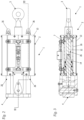
Fig. 1 ,2 and 3 illustrate, respectively in axonometric view, in plan view from above and in longitudinal section offset along two vertical planes parallel to each other, a steering drawbar according to the invention; -
Fig. 4 and 5 illustrate, in longitudinal section along a vertical plane and along a horizontal plane respectively, the steering drawbar ofFig. 1 in a first work phase; -
Fig. 6 and 7 illustrate, in longitudinal section along a vertical plane and along a horizontal plane respectively, the steering drawbar ofFig. 1 in a second work phase. - With reference to the Figures a
steering drawbar 1 is illustrated for connection between a tractor and a trailer associated with an agricultural implement. Preferably, the agricultural implement transported by the trailer comprises an atomizer for composing a spraying machine. - Said
steering drawbar 1 comprises: - a
central body 2 with a longitudinal axis of development x, having a first and a second end; - a first
swivel connection element 3 to said tractor, associated with said first end of saidcentral body 2; - a second swivel connection element 4 to said trailer, associated with said second end of said
central body 2. - Said first
swivel connection element 3 substantially comprises a joint, the so-called eye, designed to rotate around a vertical axis z orthogonal to the vehicle supporting surface. The rotation of said firstswivel connection element 3 allows the tractor to steer during towing of the trailer in ordinary road transit conditions. - Said second swivel connection element is designed to cooperate with an articulated joint rotating at least around a vertical axis, orthogonal to the vehicle supporting surface. The rotation of said second swivel connection element 4 inside said articulated joint allows the trailer to steer with respect to tractor in working conditions between the rows by over 90°. In a variation not illustrated, there may also be a joint rotating around a horizontal axis, orthogonal to the axis of horizontal development x, to allow also a pitching movement, due to the forward and backward inclinations of the tractor with respect to the trailer due to the unevenness of the ground.
- Said
central body 2 comprises a first 5 and a second 6 hydraulically operated double-acting cylinder, arranged symmetrically with respect to the longitudinal axis of development x of saidcentral body 2, alongside the same. - Each double-acting
cylinder sleeve central body 2, and astem sleeve - In the variation illustrated, the two
sleeves cylinders central body 2, while the first 25', 26' and the second 25", 26" abutment ends of the twostems - The first abutment ends 25', 26' of each
stem spherical heads 35, 36: the spherical shape of the heads guarantees that they rest stably against the tractor also in the presence of misalignments due to unevenness of the ground surface over which the tractor and trailer travel in sequence. - As can be seen from the figures, said
spherical heads stems stems cylinders - The second abutment ends 25", 26" of each
stem flat heads - Said
central body 2 comprises afirst bracket 8 proximal to said tractor and asecond bracket 9 proximal to said trailer, both designed to support said first 5 and second 6 double-acting cylinder, cooperating with therespective sleeves - Said
first bracket 8, along the longitudinal axis of development x, is stably associated with said firstswivel connection element 3 to said tractor, namely said eye. - Said
second bracket 9 is stably associated with said second swivel connection element 4 to said trailer. - For reasons of safety and protection, said
central body 2 is totally enclosed by a casing 13 (shown inFig. 2 ) associated with said first 8 and second 9 bracket. - Said steering
drawbar 1 further comprises a hydraulic circuit comprising pipes designed to be connected, by means ofspecific connections 7 and non-return or anti-reflux valves (not illustrated), to said first 5 and second 6 double-acting cylinder. - As can be seen from the sections of
Fig. 4-7 , between thesleeve stem acting piston 5, 6 adual inlet chamber - In detail, a transverse partition14 interposed between the outer surface of said
stem sleeve dual chamber separate portions chamber portion stem - Said hydraulic circuit comprises a safety valve assembly integral with said
carter 13. In particular, said valve assembly comprises stop valves designed to prevent the reflux of oil from saidchamber - Operation of the
steering drawbar 1 according to the invention is described below. - The
stem acting piston Fig. 4 and 5 ) with its first abutment end 25', 26' stopping against the tractor to block rotation of the latter around saidfirst swivel element 3, and a second retracted position towards said trailer (Fig. 6 and 7 ) and itssecond end 25", 26" stopping, at least indirectly, against the trailer to block rotation of the latter around said second swivel element 4. - It is clear that said first advanced position blocks the steering movement of the tractor and is a first condition, illustrated in
Fig. 4 and 5 , typical of when the spraying machine, or the agricultural machine in general, is operating in a field, between the rows of a vineyard or an orchard, when the steering space is reduced. - Vice versa, said second retracted position blocks the steering movement of the trailer and is a second condition, illustrated in
Fig. 6 and 7 , typical of when the spraying machine, or the agricultural machine in general, has to be moved by road from one work area to another.
Claims (9)
- A steering drawbar (1) suitable to be connected in use between a tractor and a trailer, comprising:- a central body (2) with a longitudinal axis of development (x), having a first and a second end;- a first swivel connection element (3) to said tractor, designed to act as a front steering point, associated with said first end of said central body;- a second swivel connection element (4) to said trailer, designed to act as a rear steering point, associated with said second end of said central body;- a hydraulic circuit, characterised in that the central body comprises a first and a second hydraulically operated double-acting cylinder, arranged simmetrically with respect to the longitudinal axis of development of said central body, where each double-acting cylinder comprises a sleeve, permanently associated with said central body, and a stem, having a first and a second abutment end, and where said stem is designed to move between a first advanced position towards said tractor with its first abutment end stopping against the tractor to block the rotation of the latter around said first swivel element, and a second retracted position towards said trailer with the second abutment end stopping, at least indirectly, against the trailer to block rotation of the latter around said second swivel element.
- The steering drawbar (1) according to claim 1, characterized in that said central body (2) comprises a first bracket (8) proximal to said tractor and a second bracket (9) proximal to said trailer, designed to support said first (5) and second (6) double-acting cylinder cooperating with the respective sleeves (15, 16).
- The steering drawbar (1) according to claim 2, characterized in that said first swivel connection element (3) to said tractor is stably associated with said first bracket (8).
- The steering drawbar (1) according to claim 2, characterized in that said second swivel connection element (4) to said trailer is stably associated with said second bracket (9).
- The steering drawbar (1) according to claim 1, characterized in that the first abutment ends (25', 26') of each stem (25, 26) comprise spherical heads (35, 36).
- The steering drawbar (1) according to claim 5, characterized in that said spherical heads (35, 36) are associated with said first ends (25', 26') by screw adjustment means (10).
- The steering drawbar (1) according to claim 1, characterized in that each double-acting cylinder (5, 6) comprises a first (11) and a second (12) chamber for the oil, and said hydraulic circuit comprises pipes connected to said chambers (11, 12).
- The steering drawbar (1) according to claim 7, characterized in that said hydraulic circuit comprises stop valves designed to prevent the reflux of oil from said first and second chamber (11, 12) towards said pipes.
- A spraying machine comprising a trailer with steering drawbar (1) according to at least one of the preceding claims.
Applications Claiming Priority (1)
| Application Number | Priority Date | Filing Date | Title |
|---|---|---|---|
| IT102020000024958A IT202000024958A1 (en) | 2020-10-22 | 2020-10-22 | STEERING RUDDER |
Publications (3)
| Publication Number | Publication Date |
|---|---|
| EP3987896A1 EP3987896A1 (en) | 2022-04-27 |
| EP3987896B1 true EP3987896B1 (en) | 2024-06-26 |
| EP3987896C0 EP3987896C0 (en) | 2024-06-26 |
Family
ID=74068604
Family Applications (1)
| Application Number | Title | Priority Date | Filing Date |
|---|---|---|---|
| EP21202326.1A Active EP3987896B1 (en) | 2020-10-22 | 2021-10-13 | Steering drawbar |
Country Status (2)
| Country | Link |
|---|---|
| EP (1) | EP3987896B1 (en) |
| IT (1) | IT202000024958A1 (en) |
Family Cites Families (4)
| Publication number | Priority date | Publication date | Assignee | Title |
|---|---|---|---|---|
| FR2668879A1 (en) * | 1990-11-09 | 1992-05-15 | Lucas Sa G | SYSTEM FOR HITCHING BETWEEN A TRACTOR AND A SEMI-RIDED TYPE OF TRAILER. |
| US5335856A (en) * | 1992-10-13 | 1994-08-09 | Fmc Corporation | Air boom sprayer trailer hitch and suspension |
| FR2703955B1 (en) * | 1993-04-16 | 1995-07-07 | Lucas Sa G | Improvement of the coupling system between a tractor and a tool of the semi-mounted trailer type, for example. |
| DE102007020744A1 (en) * | 2007-02-12 | 2008-08-14 | Amazonen-Werke H. Dreyer Gmbh & Co. Kg | Hydraulic cylinder especially for tractor hitch has floating pistons to lock cylinder in middle position by applying similar hydraulic pressure to both ends |
-
2020
- 2020-10-22 IT IT102020000024958A patent/IT202000024958A1/en unknown
-
2021
- 2021-10-13 EP EP21202326.1A patent/EP3987896B1/en active Active
Also Published As
| Publication number | Publication date |
|---|---|
| EP3987896A1 (en) | 2022-04-27 |
| IT202000024958A1 (en) | 2022-04-22 |
| EP3987896C0 (en) | 2024-06-26 |
Similar Documents
| Publication | Publication Date | Title |
|---|---|---|
| CA2784575C (en) | Rear folding toolbar implement | |
| US6378619B2 (en) | Agricultural ground working implement with hydraulic downpressure circuit | |
| US5136828A (en) | Farm machine which detects an intermediate position of a connecting device | |
| US5335856A (en) | Air boom sprayer trailer hitch and suspension | |
| US6119963A (en) | Full boom pivot breakaway | |
| CA2580592C (en) | Front fold planter lift and fold hydraulic control system | |
| US7849932B2 (en) | Steering and elevating wheel system for agricultural implement | |
| EP1808064B1 (en) | Self-propelled mower for large areas | |
| CA2970217C (en) | Implement with foldable toolbar system | |
| US10814911B2 (en) | Implement steering system | |
| US6263977B1 (en) | Winged agricultural implement with headlands control system | |
| US7971886B2 (en) | Steering for towed implements | |
| WO2013085762A1 (en) | Agricultural implements | |
| US20200060067A1 (en) | Implement with forward folding wing frames | |
| EP3302016B1 (en) | Semi-mounted plough | |
| EP3987896B1 (en) | Steering drawbar | |
| EP1277393B1 (en) | Support wheel arrangement for an agricultural working machine | |
| KR102915315B1 (en) | Hydraulic Steering Apparatus for Agricultural Vehicle | |
| JPH1132543A (en) | Control device for farm machine | |
| US5277265A (en) | Tow valve and interlock for a vehicle | |
| CA2252293C (en) | Agricultural ground working implement with hydraulic downpressure circuit | |
| IE20160108A1 (en) | A multipurpose trailed agricultural implement frame |
Legal Events
| Date | Code | Title | Description |
|---|---|---|---|
| PUAI | Public reference made under article 153(3) epc to a published international application that has entered the european phase |
Free format text: ORIGINAL CODE: 0009012 |
|
| STAA | Information on the status of an ep patent application or granted ep patent |
Free format text: STATUS: THE APPLICATION HAS BEEN PUBLISHED |
|
| AK | Designated contracting states |
Kind code of ref document: A1 Designated state(s): AL AT BE BG CH CY CZ DE DK EE ES FI FR GB GR HR HU IE IS IT LI LT LU LV MC MK MT NL NO PL PT RO RS SE SI SK SM TR |
|
| STAA | Information on the status of an ep patent application or granted ep patent |
Free format text: STATUS: REQUEST FOR EXAMINATION WAS MADE |
|
| 17P | Request for examination filed |
Effective date: 20221018 |
|
| RBV | Designated contracting states (corrected) |
Designated state(s): AL AT BE BG CH CY CZ DE DK EE ES FI FR GB GR HR HU IE IS IT LI LT LU LV MC MK MT NL NO PL PT RO RS SE SI SK SM TR |
|
| P01 | Opt-out of the competence of the unified patent court (upc) registered |
Effective date: 20231129 |
|
| GRAP | Despatch of communication of intention to grant a patent |
Free format text: ORIGINAL CODE: EPIDOSNIGR1 |
|
| STAA | Information on the status of an ep patent application or granted ep patent |
Free format text: STATUS: GRANT OF PATENT IS INTENDED |
|
| RIC1 | Information provided on ipc code assigned before grant |
Ipc: B60D 1/155 20060101ALI20240208BHEP Ipc: B60D 1/00 20060101ALI20240208BHEP Ipc: A01B 59/042 20060101ALI20240208BHEP Ipc: A01B 59/00 20060101AFI20240208BHEP |
|
| INTG | Intention to grant announced |
Effective date: 20240227 |
|
| GRAS | Grant fee paid |
Free format text: ORIGINAL CODE: EPIDOSNIGR3 |
|
| GRAA | (expected) grant |
Free format text: ORIGINAL CODE: 0009210 |
|
| STAA | Information on the status of an ep patent application or granted ep patent |
Free format text: STATUS: THE PATENT HAS BEEN GRANTED |
|
| AK | Designated contracting states |
Kind code of ref document: B1 Designated state(s): AL AT BE BG CH CY CZ DE DK EE ES FI FR GB GR HR HU IE IS IT LI LT LU LV MC MK MT NL NO PL PT RO RS SE SI SK SM TR |
|
| REG | Reference to a national code |
Ref country code: GB Ref legal event code: FG4D |
|
| REG | Reference to a national code |
Ref country code: CH Ref legal event code: EP |
|
| REG | Reference to a national code |
Ref country code: DE Ref legal event code: R096 Ref document number: 602021014762 Country of ref document: DE |
|
| U01 | Request for unitary effect filed |
Effective date: 20240724 |
|
| U07 | Unitary effect registered |
Designated state(s): AT BE BG DE DK EE FI FR IT LT LU LV MT NL PT SE SI Effective date: 20240805 |
|
| P04 | Withdrawal of opt-out of the competence of the unified patent court (upc) registered |
Free format text: CASE NUMBER: APP_44667/2024 Effective date: 20240731 |
|
| PG25 | Lapsed in a contracting state [announced via postgrant information from national office to epo] |
Ref country code: HR Free format text: LAPSE BECAUSE OF FAILURE TO SUBMIT A TRANSLATION OF THE DESCRIPTION OR TO PAY THE FEE WITHIN THE PRESCRIBED TIME-LIMIT Effective date: 20240626 |
|
| PG25 | Lapsed in a contracting state [announced via postgrant information from national office to epo] |
Ref country code: GR Free format text: LAPSE BECAUSE OF FAILURE TO SUBMIT A TRANSLATION OF THE DESCRIPTION OR TO PAY THE FEE WITHIN THE PRESCRIBED TIME-LIMIT Effective date: 20240927 |
|
| PG25 | Lapsed in a contracting state [announced via postgrant information from national office to epo] |
Ref country code: NO Free format text: LAPSE BECAUSE OF FAILURE TO SUBMIT A TRANSLATION OF THE DESCRIPTION OR TO PAY THE FEE WITHIN THE PRESCRIBED TIME-LIMIT Effective date: 20240926 Ref country code: HR Free format text: LAPSE BECAUSE OF FAILURE TO SUBMIT A TRANSLATION OF THE DESCRIPTION OR TO PAY THE FEE WITHIN THE PRESCRIBED TIME-LIMIT Effective date: 20240626 Ref country code: GR Free format text: LAPSE BECAUSE OF FAILURE TO SUBMIT A TRANSLATION OF THE DESCRIPTION OR TO PAY THE FEE WITHIN THE PRESCRIBED TIME-LIMIT Effective date: 20240927 Ref country code: RS Free format text: LAPSE BECAUSE OF FAILURE TO SUBMIT A TRANSLATION OF THE DESCRIPTION OR TO PAY THE FEE WITHIN THE PRESCRIBED TIME-LIMIT Effective date: 20240926 |
|
| U20 | Renewal fee for the european patent with unitary effect paid |
Year of fee payment: 4 Effective date: 20241002 |
|
| P05 | Withdrawal of opt-out of the competence of the unified patent court (upc) changed |
Free format text: CASE NUMBER: APP_44667/2024 Effective date: 20240805 |
|
| PG25 | Lapsed in a contracting state [announced via postgrant information from national office to epo] |
Ref country code: PL Free format text: LAPSE BECAUSE OF FAILURE TO SUBMIT A TRANSLATION OF THE DESCRIPTION OR TO PAY THE FEE WITHIN THE PRESCRIBED TIME-LIMIT Effective date: 20240626 |
|
| PG25 | Lapsed in a contracting state [announced via postgrant information from national office to epo] |
Ref country code: IS Free format text: LAPSE BECAUSE OF FAILURE TO SUBMIT A TRANSLATION OF THE DESCRIPTION OR TO PAY THE FEE WITHIN THE PRESCRIBED TIME-LIMIT Effective date: 20241026 |
|
| PG25 | Lapsed in a contracting state [announced via postgrant information from national office to epo] |
Ref country code: CZ Free format text: LAPSE BECAUSE OF FAILURE TO SUBMIT A TRANSLATION OF THE DESCRIPTION OR TO PAY THE FEE WITHIN THE PRESCRIBED TIME-LIMIT Effective date: 20240626 |
|
| PG25 | Lapsed in a contracting state [announced via postgrant information from national office to epo] |
Ref country code: RO Free format text: LAPSE BECAUSE OF FAILURE TO SUBMIT A TRANSLATION OF THE DESCRIPTION OR TO PAY THE FEE WITHIN THE PRESCRIBED TIME-LIMIT Effective date: 20240626 Ref country code: SK Free format text: LAPSE BECAUSE OF FAILURE TO SUBMIT A TRANSLATION OF THE DESCRIPTION OR TO PAY THE FEE WITHIN THE PRESCRIBED TIME-LIMIT Effective date: 20240626 |
|
| PG25 | Lapsed in a contracting state [announced via postgrant information from national office to epo] |
Ref country code: ES Free format text: LAPSE BECAUSE OF FAILURE TO SUBMIT A TRANSLATION OF THE DESCRIPTION OR TO PAY THE FEE WITHIN THE PRESCRIBED TIME-LIMIT Effective date: 20240626 Ref country code: SM Free format text: LAPSE BECAUSE OF FAILURE TO SUBMIT A TRANSLATION OF THE DESCRIPTION OR TO PAY THE FEE WITHIN THE PRESCRIBED TIME-LIMIT Effective date: 20240626 |
|
| PG25 | Lapsed in a contracting state [announced via postgrant information from national office to epo] |
Ref country code: SM Free format text: LAPSE BECAUSE OF FAILURE TO SUBMIT A TRANSLATION OF THE DESCRIPTION OR TO PAY THE FEE WITHIN THE PRESCRIBED TIME-LIMIT Effective date: 20240626 Ref country code: SK Free format text: LAPSE BECAUSE OF FAILURE TO SUBMIT A TRANSLATION OF THE DESCRIPTION OR TO PAY THE FEE WITHIN THE PRESCRIBED TIME-LIMIT Effective date: 20240626 Ref country code: RO Free format text: LAPSE BECAUSE OF FAILURE TO SUBMIT A TRANSLATION OF THE DESCRIPTION OR TO PAY THE FEE WITHIN THE PRESCRIBED TIME-LIMIT Effective date: 20240626 Ref country code: PL Free format text: LAPSE BECAUSE OF FAILURE TO SUBMIT A TRANSLATION OF THE DESCRIPTION OR TO PAY THE FEE WITHIN THE PRESCRIBED TIME-LIMIT Effective date: 20240626 Ref country code: IS Free format text: LAPSE BECAUSE OF FAILURE TO SUBMIT A TRANSLATION OF THE DESCRIPTION OR TO PAY THE FEE WITHIN THE PRESCRIBED TIME-LIMIT Effective date: 20241026 Ref country code: ES Free format text: LAPSE BECAUSE OF FAILURE TO SUBMIT A TRANSLATION OF THE DESCRIPTION OR TO PAY THE FEE WITHIN THE PRESCRIBED TIME-LIMIT Effective date: 20240626 Ref country code: CZ Free format text: LAPSE BECAUSE OF FAILURE TO SUBMIT A TRANSLATION OF THE DESCRIPTION OR TO PAY THE FEE WITHIN THE PRESCRIBED TIME-LIMIT Effective date: 20240626 |
|
| PLBE | No opposition filed within time limit |
Free format text: ORIGINAL CODE: 0009261 |
|
| STAA | Information on the status of an ep patent application or granted ep patent |
Free format text: STATUS: NO OPPOSITION FILED WITHIN TIME LIMIT |
|
| REG | Reference to a national code |
Ref country code: CH Ref legal event code: PL |
|
| 26N | No opposition filed |
Effective date: 20250327 |
|
| PG25 | Lapsed in a contracting state [announced via postgrant information from national office to epo] |
Ref country code: MC Free format text: LAPSE BECAUSE OF FAILURE TO SUBMIT A TRANSLATION OF THE DESCRIPTION OR TO PAY THE FEE WITHIN THE PRESCRIBED TIME-LIMIT Effective date: 20240626 |
|
| PG25 | Lapsed in a contracting state [announced via postgrant information from national office to epo] |
Ref country code: CH Free format text: LAPSE BECAUSE OF NON-PAYMENT OF DUE FEES Effective date: 20241031 |
|
| PG25 | Lapsed in a contracting state [announced via postgrant information from national office to epo] |
Ref country code: IE Free format text: LAPSE BECAUSE OF NON-PAYMENT OF DUE FEES Effective date: 20241013 |
|
| U20 | Renewal fee for the european patent with unitary effect paid |
Year of fee payment: 5 Effective date: 20250925 |
|
| PGFP | Annual fee paid to national office [announced via postgrant information from national office to epo] |
Ref country code: TR Payment date: 20251007 Year of fee payment: 5 |
|
| PG25 | Lapsed in a contracting state [announced via postgrant information from national office to epo] |
Ref country code: CY Free format text: LAPSE BECAUSE OF FAILURE TO SUBMIT A TRANSLATION OF THE DESCRIPTION OR TO PAY THE FEE WITHIN THE PRESCRIBED TIME-LIMIT; INVALID AB INITIO Effective date: 20211013 |
|
| PG25 | Lapsed in a contracting state [announced via postgrant information from national office to epo] |
Ref country code: HU Free format text: LAPSE BECAUSE OF FAILURE TO SUBMIT A TRANSLATION OF THE DESCRIPTION OR TO PAY THE FEE WITHIN THE PRESCRIBED TIME-LIMIT; INVALID AB INITIO Effective date: 20211013 |