EP3986038A1 - Power headroom reporting method and apparatus therefor - Google Patents
Power headroom reporting method and apparatus therefor Download PDFInfo
- Publication number
- EP3986038A1 EP3986038A1 EP19951979.4A EP19951979A EP3986038A1 EP 3986038 A1 EP3986038 A1 EP 3986038A1 EP 19951979 A EP19951979 A EP 19951979A EP 3986038 A1 EP3986038 A1 EP 3986038A1
- Authority
- EP
- European Patent Office
- Prior art keywords
- power headroom
- power
- transmit power
- maximum transmit
- configured maximum
- Prior art date
- Legal status (The legal status is an assumption and is not a legal conclusion. Google has not performed a legal analysis and makes no representation as to the accuracy of the status listed.)
- Granted
Links
Images




Classifications
-
- H—ELECTRICITY
- H04—ELECTRIC COMMUNICATION TECHNIQUE
- H04W—WIRELESS COMMUNICATION NETWORKS
- H04W52/00—Power management, e.g. Transmission Power Control [TPC] or power classes
- H04W52/04—Transmission power control [TPC]
- H04W52/30—Transmission power control [TPC] using constraints in the total amount of available transmission power
- H04W52/36—Transmission power control [TPC] using constraints in the total amount of available transmission power with a discrete range or set of values, e.g. step size, ramping or offsets
- H04W52/365—Power headroom reporting
-
- H—ELECTRICITY
- H04—ELECTRIC COMMUNICATION TECHNIQUE
- H04W—WIRELESS COMMUNICATION NETWORKS
- H04W52/00—Power management, e.g. Transmission Power Control [TPC] or power classes
- H04W52/04—Transmission power control [TPC]
- H04W52/06—TPC algorithms
- H04W52/14—Separate analysis of uplink or downlink
-
- H—ELECTRICITY
- H04—ELECTRIC COMMUNICATION TECHNIQUE
- H04W—WIRELESS COMMUNICATION NETWORKS
- H04W52/00—Power management, e.g. Transmission Power Control [TPC] or power classes
- H04W52/04—Transmission power control [TPC]
- H04W52/30—Transmission power control [TPC] using constraints in the total amount of available transmission power
- H04W52/34—TPC management, i.e. sharing limited amount of power among users or channels or data types, e.g. cell loading
-
- H—ELECTRICITY
- H04—ELECTRIC COMMUNICATION TECHNIQUE
- H04W—WIRELESS COMMUNICATION NETWORKS
- H04W52/00—Power management, e.g. Transmission Power Control [TPC] or power classes
- H04W52/04—Transmission power control [TPC]
- H04W52/30—Transmission power control [TPC] using constraints in the total amount of available transmission power
- H04W52/36—Transmission power control [TPC] using constraints in the total amount of available transmission power with a discrete range or set of values, e.g. step size, ramping or offsets
- H04W52/367—Power values between minimum and maximum limits, e.g. dynamic range
-
- H—ELECTRICITY
- H04—ELECTRIC COMMUNICATION TECHNIQUE
- H04W—WIRELESS COMMUNICATION NETWORKS
- H04W80/00—Wireless network protocols or protocol adaptations to wireless operation
- H04W80/02—Data link layer protocols
Definitions
- the present invention relates to the field of communication technology, and more particularly, to the technical field of power headroom reporting.
- NR-NR New Radio
- DC Dual Connectivity
- semi-static power sharing solution a semi-static power sharing solution
- dynamic power sharing solution a semi-static power sharing solution
- a network device configures two cell groups (CGs), a master cell group (MCG) and a secondary cell group (SCG), for User Equipment (UE).
- the network device will also configure a transmit power upper limit P MCG at the MCG and a transmit power upper limit P SCG at the SCG for the UE.
- the UE can work in one of the following two sub-solutions through configuring.
- the transmit power upper limit of the corresponding cell group needs to be considered when the configured maximum transmit power is calculated.
- P MCG and PSCG transmit power upper limits
- different values of the configured maximum transmit power P CMAX,f,c will be calculated according to different transmit power upper limits P MCG and PSCG, so power headroom calculated by the UE according to the configured maximum transmit power P CMAX,f,c will be different, thereby resulting in the problem of uncertain power headroom.
- the present application provides a method and apparatus for power headroom reporting, so as to solve the problem of uncertain power headroom during uplink transmission.
- the present application provides the following technical solutions.
- a method for power headroom reporting includes: configuring a cell group by a network device for a terminal device, wherein the cell group is configured with a transmit power limit, and the terminal device corresponds to a first configured maximum transmit power and a second configured maximum transmit power for the cell group; wherein the first configured maximum transmit power is determined based on the transmit power limit, and determination of the second configured maximum transmit power is irrelevant to the transmit power limit; determining, by the terminal device, according to a preset rule, to use the first configured maximum transmit power and/or the second configured maximum transmit power to obtain a power headroom report; and reporting, by the terminal device, the power headroom report.
- a method for power headroom reporting includes: configuring, by a network device, a cell group for a terminal device, wherein the cell group is configured with a transmit power limit, and the terminal device corresponds to a first configured maximum transmit power and a second configured maximum transmit power for the cell group; wherein the first configured maximum transmit power is determined based on the transmit power limit, and determination of the second configured maximum transmit power is irrelevant to the transmit power limit; sending, by the network device, configuration information to the terminal device, to enable the terminal device to determine, according to the configuration information, to use the first configured maximum transmit power and/or the second configured maximum transmit power to obtain a power headroom report; and receiving, by the network device, the power headroom report reported by the terminal device.
- An apparatus for power headroom reporting includes: a cell configuring unit configured to configure a cell group by a network device, wherein the cell group is configured with a transmit power limit, and a terminal device corresponds to a first configured maximum transmit power and a second configured maximum transmit power for the cell group; wherein the first configured maximum transmit power is determined based on the transmit power limit, and determination of the second configured maximum transmit power is irrelevant to the transmit power limit; a determining unit configured to determine, according to a preset rule, to use the first configured maximum transmit power and/or the second configured maximum transmit power to obtain a power headroom report; and a reporting unit configured to report the power headroom report.
- An apparatus for power headroom reporting includes: a network configuring unit configured to configure a cell group for a terminal device, wherein the cell group is configured with a transmit power limit, and the terminal device corresponds to a first configured maximum transmit power and a second configured maximum transmit power for the cell group; wherein the first configured maximum transmit power is determined based on the transmit power limit, and determination of the second configured maximum transmit power is irrelevant to the transmit power limit; an indicating unit configured to send configuration information to the terminal device to indicate the terminal device to determine, according to the configuration information, to use the first configured maximum transmit power and/or the second configured maximum transmit power to obtain a power headroom report; and a report receiving unit configured to receive the power headroom report reported by the terminal device.
- An uplink transmission apparatus includes a processor, a memory and a network interface; the processor invokes a program in the memory to execute a method for power headroom reporting disclosed in any embodiment, and send out an execution result through the network interface.
- a chip includes a processor for invoking and running a computer program from a memory, and a device having the chip installed thereon executes a method for power headroom reporting disclosed in any embodiment.
- a computer-readable storage medium has stored therein a program for executing a method for power reporting, which, when executed by a processor, implements a method for power headroom reporting disclosed in any embodiment.
- a computer program product is stored in a non-transitory computer-readable storage medium, wherein a computer program, when executed, implements a method for power headroom reporting disclosed in any embodiment.
- Beneficial effects of the present application lie in that during uplink transmission, the terminal device determines, through some rule, to adopt which mode to calculate the power headroom and determines specific contents of the power headroom reporting, thereby solving the problem of uncertainties in the calculation of the power headroom in uplink transmission.
- the wireless communication system includes a network device 110 and at least one terminal device 120 located in a coverage area of the network device 110.
- the wireless communication system 100 may include a plurality of network devices, and another quantity of terminal devices may be included within the coverage area of each network device, which is not limited in the embodiments of the present application.
- the wireless communication system 100 in the embodiments of the present application may be the following various communication systems, such as a Global System of Mobile Communication (GSM) system, a Code Division Multiple Access (CDMA) system, a Wideband Code Division Multiple Access (WCDMA) system, a General Packet Radio Service (GPRS), a Long Term Evolution (LTE) system, an Advanced Long Term Evolution (LTE-A) system, a New Radio (NR) system, an evolution system of the NR system, an LTE-based access to unlicensed spectrum (LTE-U) system, an NR-based access to unlicensed spectrum (NR-U) system, a Universal Mobile Telecommunications System (UMTS), Wireless Local Area Networks (WLANs), Wireless Fidelity (WiFi), a next generation communication system, or other communication systems.
- GSM Global System of Mobile Communication
- CDMA Code Division Multiple Access
- WCDMA Wideband Code Division Multiple Access
- GPRS General Packet Radio Service
- LTE Long Term Evolution
- LTE-A Advanced
- the communication system in the embodiments of the present application may be applied to a Carrier Aggregation (CA) scenario, or a Dual Connectivity (DC) scenario, or a Standalone (SA) network deployment scenario.
- CA Carrier Aggregation
- DC Dual Connectivity
- SA Standalone
- the network device 110 may provide communication coverage for a specific geographical area, and may communicate with the terminal devices (e.g., UE) located within the coverage area.
- the network device 100 may be a Base Transceiver Station (BTS) in a GSM system or CDMA system, a NodeB (NB) in a WCDMA system, an Evolutional Node B (eNB or eNodeB) in an LTE system, or a radio controller in a Cloud Radio Access Network (CRAN), or the network device may be a relay station, an access point, a vehicle-mounted device, a wearable device, a network side device in a 5G network, or a network device in a future evolved Public Land Mobile Network (PLMN).
- BTS Base Transceiver Station
- NB NodeB
- eNB or eNodeB Evolutional Node B
- CRAN Cloud Radio Access Network
- PLMN Public Land Mobile Network
- the terminal device 120 may be mobile or fixed.
- the terminal device 120 may refer to an access terminal, User Equipment (UE), a subscriber unit, a subscriber station, a mobile station, a rover station, a remote station, a remote terminal, a mobile device, a user terminal, a terminal, a wireless communication device, a user agent, or a user apparatus.
- UE User Equipment
- the access terminal may be a cellular phone, a cordless phone, a Session Initiation Protocol (SIP) phone, a Wireless Local Loop (WLL) station, a Personal Digital Assistant (PDA), a handheld device with a wireless communication function, a computing device, or other processing devices connected to a wireless modem, a vehicle-mounted device, a wearable device, a terminal device in a 5G network, or a terminal device in a future evolved Public Land Mobile Network (PLMN).
- SIP Session Initiation Protocol
- WLL Wireless Local Loop
- PDA Personal Digital Assistant
- PLMN Public Land Mobile Network
- FIG. 2 shows a method for power headroom reporting in accordance with the first embodiment of the present application, which includes the following acts S210-S230.
- a cell group is configured by a network device for a terminal device, wherein the cell group is configured with a transmit power limit P CG1 , specifically, a transmit power limit P CG1 configured by the network device for the cell group; and the terminal device corresponds to a first configured maximum transmit power and a second configured maximum transmit power for the cell group; wherein the first configured maximum transmit power is determined based on the transmit power limit P CG1 , and determination of the second configured maximum transmit power is irrelevant to the transmit power limit P CG1.
- the so-called irrelevance means that the transmit power limit P CG1 is not included in a parameter used when the second configured maximum transmit power is calculated, in other words, the transmit power limit P CG1 is not taken into account when the second configured maximum transmit power is calculated.
- the embodiments of the present application can be applied to a scenario where two cell groups are configured by the network device for the terminal device, that is, a first cell group and a second cell group are configured by the network device for the terminal device.
- two configured maximum transmit powers i.e. the first configured maximum transmit power and the second configured maximum transmit power described above
- the embodiments of the present application are not limited to be applied to this scenario.
- the technical solutions provided by the embodiments of the present application can be used.
- the terminal device determines, according to a preset rule, to use the first configured maximum transmit power and/or the second configured maximum transmit power to obtain a power headroom report.
- the terminal device reports the power headroom report.
- the power headroom report is reported through medium access control control element (MAC CE) signaling.
- MAC CE medium access control control element
- FIG. 3A and FIG. 3B show MAC CE signaling formats for reporting the power headroom report.
- FIG. 3A shows MAC CE signaling format 1
- R represents a reserved bit
- PH represents power headroom information
- P CMAX,f,c represents a maximum transmit power.
- FIG. 3A shows MAC CE signaling format 1
- R represents a reserved bit
- PH represents power headroom information
- P CMAX,f,c represents a maximum transmit power.
- 3B shows MAC CE signaling format 2
- R represents a reserved bit
- PH represents power headroom information
- P CMAX,f,c represents a maximum transmit power
- P indicates information related to calculation of the power headroom
- V indicates information related to calculation of P CMAX,f,c
- C7-C1 respectively indicate, through one bit, whether the power headroom and the maximum transmit power of a corresponding cell are reported, that is, whether the power headroom and the maximum transmit power are carried in this signaling.
- S220 of determining, by the terminal device, according to the preset rule, to use the first configured maximum transmit power and/or the second configured maximum transmit power to obtain the power headroom report includes S223.
- the terminal device determines, according to the preset rule, to use at least one of the following modes to determine the power headroom report.
- the terminal device calculates a first power headroom by using the first configured maximum transmit power; the power headroom report includes the first power headroom and/or the first configured maximum transmit power.
- the terminal device calculates a second power headroom by using the second configured maximum transmit power; the power headroom report includes the second power headroom and/or the second configured maximum transmit power.
- S223 of determining, by the terminal device, according to the preset rule, to use at least one of the following modes to determine the power headroom report includes: determining, by the terminal device, according to a protocol, to use the first mode and/or the second mode to determine the power headroom report.
- An advantage of the first mode lies in that a case where a transmission power is low, that is, a case where a transmission limit is increased additionally, is taken into key account, so as to ensure that the network knows the worst case, so that the network device performs corresponding optimization.
- An advantage of the second mode lies in that a case where a transmission power is high, that is, a case where a transmission limit is less, is taken into key account, so as to ensure that the network device can make full use of transmit power, improving the network throughput.
- An advantage of using both the first and second modes to determine the power headroom report lies in that both the case where the transmission power is low and the case where the transmission power is high are taken into account, which is more comprehensive.
- S223 of determining, by the terminal device, according to the preset rule, to use at least one of the following modes to determine the power headroom report includes: determining, by the terminal device, according to configuration information, to use the first mode and/or the second mode to determine the power headroom report.
- S220 of determining, by the terminal device, according to the preset rule, to use the first configured maximum transmit power and/or the second configured maximum transmit power to obtain the power headroom report further includes S221.
- the configuration information sent by the network device is received, wherein the configuration information is used for indicating the terminal device to determine, according to the configuration information, to use the first configured maximum transmit power and/or the second configured maximum transmit power to obtain the power headroom report.
- both the first mode and the second mode are adopted, and the power headroom report can be any one of the following combinational information: the first power headroom, and/or the first configured maximum transmit power; and the second power headroom, and/or the second configured maximum transmit power.
- the power headroom report is determined by using both the first mode and the second mode, and the power headroom report can be any one of the following combinational information:
- an advantage of the combinational information 2) to 7) above lies in that the reported information can be reduced and the overhead can be reduced.
- the network configuration is sent to the terminal device through radio resource control (RRC) signaling or medium access control control element (MAC CE) signaling.
- RRC radio resource control
- MAC CE medium access control control element
- FIG. 4 it shows a power headroom report in which combinational information 1) is reported by using MAC CE signaling format 1.
- FIGs. 5A and 5B they show power headroom reports in which combinational information 4) is reported by using MAC CE signaling format 1.
- FIGs. 6A and 6B they show power headroom reports in which combinational information 5) is reported by using MAC CE signaling format 1.
- FIG. 7 it shows a power headroom report in which combinational information 6) is reported by using MAC CE signaling format 1.
- FIGs. 8A and 8B show power headroom reports in which combinational information 7) is reported by using MAC CE signaling format 1.
- An example of reporting the power headroom report by using MAC CE signaling format 2 is the same as or similar to the example of reporting the power headroom report by using MAC CE signaling format 1, which is given only in the first embodiment, and will not be repeated herein.
- an order in which information is reported can be more other orders.
- an order, in which the information is arranged, in the MAC CE signaling can be preset by a protocol; which type of information the corresponding information is can also be indicated by using reserved bits in an MAC CE signaling format.
- the original reserved bits R are used for indicating whether the corresponding information is the first power headroom or the second power headroom, and whether it is the first configured maximum transmit power or the second configured maximum transmit power.
- S223 of determining, by the terminal device, according to the preset rule, to use at least one of the following modes to determine the power headroom report includes: determining, by the terminal device, according to a type of the power headroom report, to use the first mode and/or the second mode to determine the power headroom report. Its advantage lies in that different reporting modes are determined according to different types of the report, so that the network can know more information and provide more optimization spaces for parameter configuration and scheduling.
- the types of the power headroom report include type 1 PHR and type 3 PHR.
- the type 1 PHR adopts the first mode to determine the power headroom report
- the type 3 PHR adopts the second mode to determine the power headroom report.
- the type 1 PHR adopts the second mode and the type 3 PHR adopts the first mode.
- the power headroom is determined according to a difference between the configured maximum transmit power P cmax,f,c (nominal UE maximum transmit power or configured maximum output power) of the terminal device and the transmit power of data channel (the estimated power for UL-SCH transmission), wherein c represents a serving cell, and f represents a carrier f of the serving cell c.
- P cmax,f,c nominal UE maximum transmit power or configured maximum output power
- f represents a carrier f of the serving cell c.
- SUL Supplemental UL
- the terminal device can calculate the power headroom (PH) according to actual PUSCH transmission, or calculate the power headroom according to reference PUSCH transmission, that is, no actual PUSCH transmission occurs, and the power headroom is calculated according to some parameters corresponding to the PUSCH transmission.
- the power headroom is determined according to a difference between the configured maximum transmit power P CMAX,f,c of the terminal device and channel sounding reference signal (SRS) transmit power.
- the terminal device can calculate the power headroom according to actual SRS transmission, or calculate the power headroom according to reference SRS transmission, that is, the actual SRS transmission does not occur, and the power headroom is calculated according to some parameters corresponding to the SRS transmission.
- the configured maximum transmit power includes the first configured maximum transmit power and/or the second configured maximum transmit power.
- S223 of determining, by the terminal device, according to the preset rule, to use at least one of the following modes to determine the power headroom report includes: determining, by the terminal device, according to whether the power headroom report is calculated based on actual transmission or reference transmission, to use the first mode and/or the second mode to determine the power headroom report. Its advantage lies in that different information is reported according to the power headroom calculated based on the actual transmission or the reference transmission, so that the network can know more information and provide more optimization spaces for parameter configuration and scheduling.
- the power headroom report is calculated based on the actual transmission, it is determined to use the first mode to determine the power headroom report; and/or if the power headroom report is calculated based on the reference transmission, it is determined to use the second mode to determine the power headroom report.
- determining, by the terminal device, according to whether the power headroom report is calculated based on the actual transmission or the reference transmission, to use the first mode and/or the second mode to determine the power headroom report includes:
- S223 of determining, by the terminal device, according to the preset rule, to use at least one of the following modes to determine the power headroom report includes: choosing voluntarily, by the terminal device, to use the first mode and/or the second mode to determine the power headroom report.
- the terminal device indicates in the power headroom report that the power headroom report is determined by using the first mode and/or the second mode.
- the power headroom report is reported by using MAC CE signaling format 1 when the terminal device chooses voluntarily the mode of reporting the power headroom.
- At least one of the reserved bits in MAC CE signaling format 1 is used to indicate whether it is the first power headroom or the second power headroom, and whether it is the first configured maximum transmit power or the second configured maximum transmit power.
- F indicates whether it corresponds to the first power headroom/the first configured maximum transmit power or the second power headroom/the second configured maximum transmit power.
- F can be any one of four reserved bits R.
- the first F indicates whether it is the first power headroom or the second power headroom, and the first F can be one of two reserved bits R in the first row; the second F indicates whether it is the first configured maximum transmit power or the second configured maximum transmit power, and the second F can be any one of two reserved bits R in the second row.
- the first F indicates whether it is the first power headroom or the second power headroom, and F can be any one of two reserved bits R in the first row;
- the second F indicates whether it is the first configured maximum transmit power or the second configured maximum transmit power, and the second F can be any one of two reserved bits R in the second row;
- the third F indicates whether it corresponds to the first power headroom or the second power headroom, and the third F can be any one of two reserved bits R in the third row;
- the fourth F indicates whether it corresponds to the first configured maximum transmit power or the second configured maximum transmit power, and the fourth F can be any one of two reserved bits R in the fourth row.
- An example of reporting the power headroom report by using MAC CE signaling format 2 is the same as or similar to the example of reporting the power headroom report by using MAC CE signaling format 1, which is given only in the first embodiment, and will not be repeated herein.
- S223 of determining, by the terminal device, according to the preset rule, to use at least one of the following modes to determine the power headroom report includes: using, by the terminal device, the first configured maximum transmit power to calculate the first power headroom.
- the terminal device determines the power headroom report by using the second mode; otherwise, the terminal device determines the power headroom report by using the first mode.
- the transmit power limit is configured in a radio resource control information element (RRC IE). Specifically, the transmit power limit is configured in PhysicalCellGroupConfig of the RRC IE.
- the first transmit power limit PCG1 is configured through one of the following RRC parameters: p-MCG-FR1, p-SCG-FR1, p-MCG-FR2, p-SCG-FR2, p-NR-FR1 and p-NR-FR2 ⁇
- the first cell group and the second cell group are in the same frequency band.
- both the first cell group and the second cell group are in an FR1 frequency band; or both the first cell group and the second cell group are in an FR2 frequency band.
- the FR1 frequency band is 410 MHz - 7125 MHz; the FR2 frequency band is 24250 MHz - 52600 MHz.
- a power sharing mode between the first cell group and the second cell group is configured by the network device or reported by the terminal device.
- the power sharing mode is configured by an RRC parameter.
- the RRC parameter is NR-DC-PC-mode, which is configured in RRC IE PhysicalCellGroupConFIG.
- the power headroom report is transmitted through the first cell group or the second cell group.
- the terminal device determines, through some rule, to adopt which mode to calculate the power headroom and determines specific contents of reporting of the power headroom, thereby solving the problem of uncertainties in the calculation of the power headroom.
- FIG. 10 it shows an apparatus 300 for transmitting uplink information in accordance with the second embodiment of the present application.
- the apparatus includes: a cell configuring unit 310, a determining unit 320, and a reporting unit 330.
- the cell configuring unit 310 is configured to configure a cell group by a network, wherein the cell group is configured with a transmit power limit P CG1 , and a terminal device corresponds to a first configured maximum transmit power and a second configured maximum transmit power for the cell group; wherein the first configured maximum transmit power is determined based on the transmit power limit P CG1 , and determination of the second configured maximum transmit power is irrelevant to the transmit power limit P CG1 .
- the determining unit 320 is configured to determine, according to a preset rule, to use the first configured maximum transmit power and/or the second configured maximum transmit power to obtain a power headroom report.
- the reporting unit 330 is configured to report the power headroom report.
- the determining unit 320 is specifically configured to determine, according to the preset rule, to use at least one of the following modes to determine the power headroom report.
- the first power headroom is calculated by using the first configured maximum transmit power; the power headroom report includes the first power headroom and/or the first configured maximum transmit power.
- the second power headroom is calculated by using the second configured maximum transmit power; the power headroom report includes the second power headroom and/or the second configured maximum transmit power.
- the determining unit 320 is specifically configured to determine, according to the protocol, to use the first mode and/or the second mode to determine the power headroom report.
- the determining unit 320 is specifically configured to determine, according to network configuration, to use the first mode and/or the second mode to determine the power headroom report.
- the power headroom report includes any one of the following combinational information:
- the network configuration is sent to the terminal device through radio resource control (RRC) signaling or medium access control control element (MAC CE) signaling.
- RRC radio resource control
- MAC CE medium access control control element
- the reporting unit 330 is specifically configured to report the power headroom report through the MAC CE signaling.
- an order, in which the information is arranged, in the MAC CE signaling is preset by a protocol; and/or reserved bits in an MAC CE signaling format are used for indicating that the corresponding information is one of the first power headroom, the second power headroom, the first configured maximum transmit power, and the second configured maximum transmit power.
- the determining unit 320 is specifically configured to determine, according to a type of the power headroom report, to use the first mode and/or the second mode to determine the power headroom report.
- the determining unit 320 is specifically configured to determine, according to whether the power headroom report is calculated based on actual transmission or reference transmission, to use the first mode and/or the second mode to determine the power headroom report.
- the determining unit 320 is specifically configured to, if the power headroom report is calculated based on the reference transmission, use the second mode to determine the power headroom report; or if the power headroom report is calculated based on the actual transmission, when the actual transmission is overlapped with transmission or potential transmission on the second cell group in the time domain, use the first mode to determine the power headroom report, otherwise, use the second mode to determine the power headroom report.
- the determining unit 320 is specifically configured to choose voluntarily to use the first mode and/or the second mode to determine the power headroom report.
- the determining unit 320 is further configured to indicate in the power headroom report that the first mode and/or the second mode is used for determining the power headroom report.
- the determining unit 320 is specifically configured to calculate the first power headroom by using the first configured maximum transmit power; use, by the terminal device, the second mode to determine the power headroom report when the first power headroom is less than or equal to 0; otherwise, use, by the terminal device, the first mode to determine the power headroom report.
- FIG. 11 it is a block diagram of an apparatus 400 for transmitting uplink information in accordance with the third embodiment of the present application.
- the apparatus includes: a network configuring unit 410, an indicating unit 420, and a report receiving unit 430.
- the network configuring unit 410 is configured to configure a cell group for a terminal device, wherein the cell group is configured with a transmit power limit P CG1 , and the terminal device corresponds to a first configured maximum transmit power and a second configured maximum transmit power for the cell group; wherein the first configured maximum transmit power is determined based on the transmit power limit P CG1 , and determination of the second configured maximum transmit power is irrelevant to the transmit power limit P CG1 .
- the indicating unit 420 is configured to send configuration information to the terminal device to indicate the terminal device to determine, according to the configuration information, to use the first configured maximum transmit power and/or the second configured maximum transmit power to obtain a power headroom report.
- the report receiving unit 430 is configured to receive the power headroom report reported by the terminal device.
- the configuration information is used for indicating whether the terminal device uses the first mode or the second mode to determine the power headroom report.
- the indicating unit 420 is configured to send the configuration information to the terminal device through radio resource control (RRC) signaling or medium access control control element (MAC CE) signaling.
- RRC radio resource control
- MAC CE medium access control control element
- the report receiving unit 430 is specifically configured to receive the power headroom report reported by the terminal device through the MAC CE signaling.
- the MAC CE signaling For specific formats and contents of the MAC CE signaling, reference is made to the contents in the first embodiment described above and this will not be repeated herein.
- the network configuring unit 410 is configured to configure the transmit power limit through a radio resource control information element (RRC IE).
- RRC IE radio resource control information element
- the network device configures two cell groups, i.e., a first cell group and a second cell group, for the terminal device, the first cell group and the second cell group are in the same frequency band.
- the report receiving unit is configured to receive the power headroom report through the first cell group or the second cell group.
- FIG. 12 it is a schematic structural diagram of an apparatus 500 for transmitting uplink information in accordance with the fourth embodiment of the present application.
- the compression apparatus 500 includes a processor 510, a memory 520, and a network interface 530.
- the processor 510 invokes a program in the memory 520 to execute an uplink transmission method in accordance with the first embodiment, and send out an execution result through the network interface 530.
- the processor 510 may be an independent component or a unified name of a plurality of processing elements.
- the processor may be a CPU, an ASIC, or one or more integrated circuits configured to implement the methods described above, such as at least one digital signal processor (DSP) or at least one field programmable gate array (FPGA).
- DSP digital signal processor
- FPGA field programmable gate array
- These computer program instructions may be provided to a general purpose computer, a special purpose computer, an embedded processor, a chip, or processors of other programmable data processing devices to generate a machine, such that the instructions, which are executed by the computers or the processors of other programmable data processing devices, can generate an apparatus for implementing functions specified in one or more flows in the flowcharts and/or one or more blocks in the block diagrams.
- the program may be stored in a computer-readable storage medium, which may include a Read Only Memory (ROM), a Random Access Memory (RAM), a magnetic disk or optical disk, etc.
Landscapes
- Engineering & Computer Science (AREA)
- Computer Networks & Wireless Communication (AREA)
- Signal Processing (AREA)
- Mobile Radio Communication Systems (AREA)
Abstract
Description
- The present invention relates to the field of communication technology, and more particularly, to the technical field of power headroom reporting.
- In NR-NR (New Radio) DC (Dual Connectivity), there are two types of power sharing (or known as power control) solutions: a semi-static power sharing solution and a dynamic power sharing solution.
- In NR-NR DC, a network device configures two cell groups (CGs), a master cell group (MCG) and a secondary cell group (SCG), for User Equipment (UE). The network device will also configure a transmit power upper limit PMCG at the MCG and a transmit power upper limit PSCG at the SCG for the UE.
- For the semi-static power sharing solution, the UE can work in one of the following two sub-solutions through configuring.
- In
sub-solution 1, during actual transmission, actual transmit powers of the UE in uplink transmissions corresponding to the MCG and the SCG cannot exceed the corresponding transmit power upper limits PMCG and PSCG configured by the network device. - In
sub-solution 2, if an uplink transmission resource on a certain CG overlaps with a semi-statically configured downlink (DL) symbol on another CG, the maximum transmit power on this CG can reach a transmit power upper limit of the UE; this upper limit is determined by RAN4, at this point PMCG and PSCG do not need to be considered when the configured maximum transmit power PCMAX,f,c on this CG is calculated. On the contrary, if uplink transmission on a certain CG overlaps with a semi-statically configured uplink or flexible symbol on another CG, its actual transmit power cannot exceed its corresponding upper limit, at this point PMCG and PSCG need to be considered when PCMAX,f,c on this CG is calculated. - For the dynamic power sharing/control solution, if uplink transmission on a certain CG overlaps with uplink transmission on another CG, actual transmit power on the corresponding CG cannot exceed its corresponding upper limit, at this point PMCG and PSCG need to be considered when PCMAX,f,c on this CG is calculated. If uplink transmission on a certain CG does not overlap with uplink transmission on another CG, the maximum transmit power on this CG can reach the transmit power upper limit of the UE, at this point PMCG and PSCG do not need to be considered when PCMAX,f,c on this CG is calculated.
- To sum up, whether in the semi-static power sharing solution or the dynamic power sharing solution, the transmit power upper limit of the corresponding cell group needs to be considered when the configured maximum transmit power is calculated. When there are two cell groups, there will be two transmit power upper limits, i.e., PMCG and PSCG. Then, different values of the configured maximum transmit power PCMAX,f,c will be calculated according to different transmit power upper limits PMCG and PSCG, so power headroom calculated by the UE according to the configured maximum transmit power PCMAX,f,c will be different, thereby resulting in the problem of uncertain power headroom.
- The present application provides a method and apparatus for power headroom reporting, so as to solve the problem of uncertain power headroom during uplink transmission.
- The present application provides the following technical solutions.
- A method for power headroom reporting includes: configuring a cell group by a network device for a terminal device, wherein the cell group is configured with a transmit power limit, and the terminal device corresponds to a first configured maximum transmit power and a second configured maximum transmit power for the cell group; wherein the first configured maximum transmit power is determined based on the transmit power limit, and determination of the second configured maximum transmit power is irrelevant to the transmit power limit; determining, by the terminal device, according to a preset rule, to use the first configured maximum transmit power and/or the second configured maximum transmit power to obtain a power headroom report; and reporting, by the terminal device, the power headroom report.
- A method for power headroom reporting includes: configuring, by a network device, a cell group for a terminal device, wherein the cell group is configured with a transmit power limit, and the terminal device corresponds to a first configured maximum transmit power and a second configured maximum transmit power for the cell group; wherein the first configured maximum transmit power is determined based on the transmit power limit, and determination of the second configured maximum transmit power is irrelevant to the transmit power limit; sending, by the network device, configuration information to the terminal device, to enable the terminal device to determine, according to the configuration information, to use the first configured maximum transmit power and/or the second configured maximum transmit power to obtain a power headroom report; and receiving, by the network device, the power headroom report reported by the terminal device.
- An apparatus for power headroom reporting includes: a cell configuring unit configured to configure a cell group by a network device, wherein the cell group is configured with a transmit power limit, and a terminal device corresponds to a first configured maximum transmit power and a second configured maximum transmit power for the cell group; wherein the first configured maximum transmit power is determined based on the transmit power limit, and determination of the second configured maximum transmit power is irrelevant to the transmit power limit; a determining unit configured to determine, according to a preset rule, to use the first configured maximum transmit power and/or the second configured maximum transmit power to obtain a power headroom report; and a reporting unit configured to report the power headroom report.
- An apparatus for power headroom reporting includes: a network configuring unit configured to configure a cell group for a terminal device, wherein the cell group is configured with a transmit power limit, and the terminal device corresponds to a first configured maximum transmit power and a second configured maximum transmit power for the cell group; wherein the first configured maximum transmit power is determined based on the transmit power limit, and determination of the second configured maximum transmit power is irrelevant to the transmit power limit; an indicating unit configured to send configuration information to the terminal device to indicate the terminal device to determine, according to the configuration information, to use the first configured maximum transmit power and/or the second configured maximum transmit power to obtain a power headroom report; and a report receiving unit configured to receive the power headroom report reported by the terminal device.
- An uplink transmission apparatus includes a processor, a memory and a network interface; the processor invokes a program in the memory to execute a method for power headroom reporting disclosed in any embodiment, and send out an execution result through the network interface.
- A chip includes a processor for invoking and running a computer program from a memory, and a device having the chip installed thereon executes a method for power headroom reporting disclosed in any embodiment.
- A computer-readable storage medium has stored therein a program for executing a method for power reporting, which, when executed by a processor, implements a method for power headroom reporting disclosed in any embodiment.
- A computer program product is stored in a non-transitory computer-readable storage medium, wherein a computer program, when executed, implements a method for power headroom reporting disclosed in any embodiment.
- Beneficial effects of the present application lie in that during uplink transmission, the terminal device determines, through some rule, to adopt which mode to calculate the power headroom and determines specific contents of the power headroom reporting, thereby solving the problem of uncertainties in the calculation of the power headroom in uplink transmission.
-
-
FIG. 1 is a system architecture diagram applied in an embodiment of the present application. -
FIG. 2 is a flowchart of a method for power headroom reporting in accordance with the first embodiment of the present application. -
FIG. 3A is a schematic diagram of MACCE signaling format 1 in accordance with the first embodiment of the present application. -
FIG. 3B is a schematic diagram of MACCE signaling format 2 in accordance with the first embodiment of the present application. -
FIG. 4 is a schematic diagram in which combinational information 1) is reported using MACCE signaling format 1. -
FIGs. 5A and 5B are schematic diagrams in which combinational information 4) is reported using MACCE signaling format 1. -
FIGs. 6A and 6B are schematic diagrams in which combinational information 5) is reported using MACCE signaling format 1. -
FIG. 7 is a schematic diagram in which combinational information 6) is reported using MACCE signaling format 1. -
Figs. 8A and 8B are schematic diagrams in which combinational information 7) is reported using MACCE signaling format 1. -
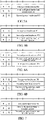
Figs. 9A to 9C are schematic diagrams in which MACCE signaling format 1 is used when a terminal device chooses voluntarily a mode of reporting power headroom. -
FIG. 10 is a block diagram of an apparatus for transmitting uplink information in accordance with the second embodiment of the present application. -
FIG. 11 is a block diagram of an apparatus for transmitting uplink information in accordance with the third embodiment of the present application. -
FIG. 12 is a schematic structure diagram of an apparatus for transmitting uplink information in accordance with the fourth embodiment of the present application. - In order to make objects, technical solutions and advantages of the present application clearer, the present application will be described in further detail below in conjunction with the drawings and embodiments. It should be understood that the embodiments described herein are only for the purpose of explaining the present application but are not intended to limit the present application. However, the present application may be implemented in many different forms but is not limited to the specific embodiments described herein. On the contrary, the purpose of providing these embodiments is to make the understanding of the disclosed contents of the present model utility more thorough and comprehensive.
- Unless otherwise defined, all technical and scientific terms used herein have same meanings as those commonly understood by those skilled in the technical field of the present application. Terms used in the description of the present application herein are for the purpose of describing specific embodiments only, but are not intended to limit the present application. The term "and/or" used herein includes any and all of combinations of one or more related listed items.
- Referring to
FIG. 1 , it shows awireless communication system 100 applied in an embodiment of the present application. The wireless communication system includes anetwork device 110 and at least oneterminal device 120 located in a coverage area of thenetwork device 110. - Optionally, the
wireless communication system 100 may include a plurality of network devices, and another quantity of terminal devices may be included within the coverage area of each network device, which is not limited in the embodiments of the present application. - The
wireless communication system 100 in the embodiments of the present application may be the following various communication systems, such as a Global System of Mobile Communication (GSM) system, a Code Division Multiple Access (CDMA) system, a Wideband Code Division Multiple Access (WCDMA) system, a General Packet Radio Service (GPRS), a Long Term Evolution (LTE) system, an Advanced Long Term Evolution (LTE-A) system, a New Radio (NR) system, an evolution system of the NR system, an LTE-based access to unlicensed spectrum (LTE-U) system, an NR-based access to unlicensed spectrum (NR-U) system, a Universal Mobile Telecommunications System (UMTS), Wireless Local Area Networks (WLANs), Wireless Fidelity (WiFi), a next generation communication system, or other communication systems. - Optionally, the communication system in the embodiments of the present application may be applied to a Carrier Aggregation (CA) scenario, or a Dual Connectivity (DC) scenario, or a Standalone (SA) network deployment scenario.
- The
network device 110 may provide communication coverage for a specific geographical area, and may communicate with the terminal devices (e.g., UE) located within the coverage area. Optionally, thenetwork device 100 may be a Base Transceiver Station (BTS) in a GSM system or CDMA system, a NodeB (NB) in a WCDMA system, an Evolutional Node B (eNB or eNodeB) in an LTE system, or a radio controller in a Cloud Radio Access Network (CRAN), or the network device may be a relay station, an access point, a vehicle-mounted device, a wearable device, a network side device in a 5G network, or a network device in a future evolved Public Land Mobile Network (PLMN). - The
terminal device 120 may be mobile or fixed. Optionally, theterminal device 120 may refer to an access terminal, User Equipment (UE), a subscriber unit, a subscriber station, a mobile station, a rover station, a remote station, a remote terminal, a mobile device, a user terminal, a terminal, a wireless communication device, a user agent, or a user apparatus. The access terminal may be a cellular phone, a cordless phone, a Session Initiation Protocol (SIP) phone, a Wireless Local Loop (WLL) station, a Personal Digital Assistant (PDA), a handheld device with a wireless communication function, a computing device, or other processing devices connected to a wireless modem, a vehicle-mounted device, a wearable device, a terminal device in a 5G network, or a terminal device in a future evolved Public Land Mobile Network (PLMN). - In the following specific embodiments of the present application, it will be revealed how a mode for calculating power headroom is determined in NR-NR DC, and the power headroom is determined to be reported according to the determined mode for calculating the power headroom.
- Referring to
FIG. 2 , it shows a method for power headroom reporting in accordance with the first embodiment of the present application, which includes the following acts S210-S230. - In S210, a cell group (CG) is configured by a network device for a terminal device, wherein the cell group is configured with a transmit power limit PCG1, specifically, a transmit power limit PCG1 configured by the network device for the cell group; and the terminal device corresponds to a first configured maximum transmit power and a second configured maximum transmit power for the cell group; wherein the first configured maximum transmit power is determined based on the transmit power limit PCG1, and determination of the second configured maximum transmit power is irrelevant to the transmit power limit PCG1. In the present application, the so-called irrelevance means that the transmit power limit PCG1 is not included in a parameter used when the second configured maximum transmit power is calculated, in other words, the transmit power limit PCG1 is not taken into account when the second configured maximum transmit power is calculated.
- It should be noted that the embodiments of the present application can be applied to a scenario where two cell groups are configured by the network device for the terminal device, that is, a first cell group and a second cell group are configured by the network device for the terminal device. When there is overlapping in uplink transmission of the terminal device in the first cell group and the second cell group, then there will be two configured maximum transmit powers (i.e. the first configured maximum transmit power and the second configured maximum transmit power described above) in the uplink transmission of the terminal device in one of the cell groups (such as the first cell group). Of course, the embodiments of the present application are not limited to be applied to this scenario. As long as there are at least two configured maximum transmit powers for the terminal device in a cell group, resulting in uncertainties in the mode of calculating the power headroom, the technical solutions provided by the embodiments of the present application can be used.
- In S220, the terminal device determines, according to a preset rule, to use the first configured maximum transmit power and/or the second configured maximum transmit power to obtain a power headroom report.
- In S230, the terminal device reports the power headroom report.
- Optionally, the power headroom report is reported through medium access control control element (MAC CE) signaling. Referring to
FIG. 3A andFIG. 3B , they show MAC CE signaling formats for reporting the power headroom report.FIG. 3A shows MACCE signaling format 1, R represents a reserved bit, PH represents power headroom information, and PCMAX,f,c represents a maximum transmit power.FIG. 3B shows MACCE signaling format 2, R represents a reserved bit, PH represents power headroom information, PCMAX,f,c represents a maximum transmit power, P indicates information related to calculation of the power headroom, V indicates information related to calculation of PCMAX,f,c, and C7-C1 respectively indicate, through one bit, whether the power headroom and the maximum transmit power of a corresponding cell are reported, that is, whether the power headroom and the maximum transmit power are carried in this signaling. - Optionally, S220 of determining, by the terminal device, according to the preset rule, to use the first configured maximum transmit power and/or the second configured maximum transmit power to obtain the power headroom report includes S223.
- In S223, the terminal device determines, according to the preset rule, to use at least one of the following modes to determine the power headroom report.
- In a first mode, the terminal device calculates a first power headroom by using the first configured maximum transmit power; the power headroom report includes the first power headroom and/or the first configured maximum transmit power.
- In a second mode, the terminal device calculates a second power headroom by using the second configured maximum transmit power; the power headroom report includes the second power headroom and/or the second configured maximum transmit power.
- Optionally, S223 of determining, by the terminal device, according to the preset rule, to use at least one of the following modes to determine the power headroom report includes:
determining, by the terminal device, according to a protocol, to use the first mode and/or the second mode to determine the power headroom report. - An advantage of the first mode lies in that a case where a transmission power is low, that is, a case where a transmission limit is increased additionally, is taken into key account, so as to ensure that the network knows the worst case, so that the network device performs corresponding optimization.
- An advantage of the second mode lies in that a case where a transmission power is high, that is, a case where a transmission limit is less, is taken into key account, so as to ensure that the network device can make full use of transmit power, improving the network throughput.
- An advantage of using both the first and second modes to determine the power headroom report lies in that both the case where the transmission power is low and the case where the transmission power is high are taken into account, which is more comprehensive.
- Optionally, S223 of determining, by the terminal device, according to the preset rule, to use at least one of the following modes to determine the power headroom report includes: determining, by the terminal device, according to configuration information, to use the first mode and/or the second mode to determine the power headroom report. An advantage of determining the mode of reporting the power headroom according to the configuration information lies in that the flexibility of the network is increased and an optimization space is provided for the improvement of network performance.
- When the terminal device determines the mode of reporting the power headroom according to the configuration information in S223, optionally, S220 of determining, by the terminal device, according to the preset rule, to use the first configured maximum transmit power and/or the second configured maximum transmit power to obtain the power headroom report further includes S221.
- In S221, the configuration information sent by the network device is received, wherein the configuration information is used for indicating the terminal device to determine, according to the configuration information, to use the first configured maximum transmit power and/or the second configured maximum transmit power to obtain the power headroom report.
- Optionally, both the first mode and the second mode are adopted, and the power headroom report can be any one of the following combinational information:
the first power headroom, and/or the first configured maximum transmit power; and the second power headroom, and/or the second configured maximum transmit power. - Optionally, the power headroom report is determined by using both the first mode and the second mode, and the power headroom report can be any one of the following combinational information:
- 1) the first power headroom, the second power headroom, the first configured maximum transmit power, and the second configured maximum transmit power;
- 2) the first configured maximum transmit power and the second configured maximum transmit power;
- 3) the first power headroom and the second power headroom;
- 4) the first power headroom, the second power headroom, and the first configured maximum transmit power;
- 5) the first power headroom, the second power headroom, and the second configured maximum transmit power;
- 6) the first power headroom, the first configured maximum transmit power, and the second configured maximum transmit power; and
- 7) the second power headroom, the first configured maximum transmit power, and the second configured maximum transmit power.
- Compared with the combinational information 1), an advantage of the combinational information 2) to 7) above lies in that the reported information can be reduced and the overhead can be reduced.
- Optionally, the network configuration is sent to the terminal device through radio resource control (RRC) signaling or medium access control control element (MAC CE) signaling.
- Referring to
FIG. 4 , it shows a power headroom report in which combinational information 1) is reported by using MACCE signaling format 1. - Referring to
FIGs. 5A and 5B , they show power headroom reports in which combinational information 4) is reported by using MACCE signaling format 1. - Referring to
FIGs. 6A and 6B , they show power headroom reports in which combinational information 5) is reported by using MACCE signaling format 1. - Referring to
FIG. 7 , it shows a power headroom report in which combinational information 6) is reported by using MACCE signaling format 1. - Referring to
FIGs. 8A and 8B , they show power headroom reports in which combinational information 7) is reported by using MACCE signaling format 1. - An example of reporting the power headroom report by using MAC
CE signaling format 2 is the same as or similar to the example of reporting the power headroom report by using MACCE signaling format 1, which is given only in the first embodiment, and will not be repeated herein. - The contents shown in
FIGs. 4 to 8 above are only some of the examples, herein an order in which information is reported can be more other orders. Optionally, an order, in which the information is arranged, in the MAC CE signaling can be preset by a protocol; which type of information the corresponding information is can also be indicated by using reserved bits in an MAC CE signaling format. Specifically, as shown inFIG. 9 below, the original reserved bits R are used for indicating whether the corresponding information is the first power headroom or the second power headroom, and whether it is the first configured maximum transmit power or the second configured maximum transmit power. - Optionally, S223 of determining, by the terminal device, according to the preset rule, to use at least one of the following modes to determine the power headroom report includes:
determining, by the terminal device, according to a type of the power headroom report, to use the first mode and/or the second mode to determine the power headroom report. Its advantage lies in that different reporting modes are determined according to different types of the report, so that the network can know more information and provide more optimization spaces for parameter configuration and scheduling. - The types of the power headroom report include
type 1 PHR andtype 3 PHR. Optionally, thetype 1 PHR adopts the first mode to determine the power headroom report, and thetype 3 PHR adopts the second mode to determine the power headroom report. Optionally, thetype 1 PHR adopts the second mode and thetype 3 PHR adopts the first mode. - For the
type 1 PHR, the power headroom is determined according to a difference between the configured maximum transmit power Pcmax,f,c (nominal UE maximum transmit power or configured maximum output power) of the terminal device and the transmit power of data channel (the estimated power for UL-SCH transmission), wherein c represents a serving cell, and f represents a carrier f of the serving cell c. For example, when there is supplementary UL (SUL), one serving cell has two carriers. The terminal device can calculate the power headroom (PH) according to actual PUSCH transmission, or calculate the power headroom according to reference PUSCH transmission, that is, no actual PUSCH transmission occurs, and the power headroom is calculated according to some parameters corresponding to the PUSCH transmission. - For the
type 3 PHR, the power headroom is determined according to a difference between the configured maximum transmit power PCMAX,f,c of the terminal device and channel sounding reference signal (SRS) transmit power. The terminal device can calculate the power headroom according to actual SRS transmission, or calculate the power headroom according to reference SRS transmission, that is, the actual SRS transmission does not occur, and the power headroom is calculated according to some parameters corresponding to the SRS transmission. The configured maximum transmit power includes the first configured maximum transmit power and/or the second configured maximum transmit power. - Optionally, S223 of determining, by the terminal device, according to the preset rule, to use at least one of the following modes to determine the power headroom report includes:
determining, by the terminal device, according to whether the power headroom report is calculated based on actual transmission or reference transmission, to use the first mode and/or the second mode to determine the power headroom report. Its advantage lies in that different information is reported according to the power headroom calculated based on the actual transmission or the reference transmission, so that the network can know more information and provide more optimization spaces for parameter configuration and scheduling. - Optionally, if the power headroom report is calculated based on the actual transmission, it is determined to use the first mode to determine the power headroom report; and/or if the power headroom report is calculated based on the reference transmission, it is determined to use the second mode to determine the power headroom report.
- Optionally, if the power headroom report is calculated based on the actual transmission, it is determined to use the second mode to determine the power headroom report; and/or if the power headroom report is calculated based on the reference transmission, it is determined to use the first mode to determine the power headroom report. Optionally, determining, by the terminal device, according to whether the power headroom report is calculated based on the actual transmission or the reference transmission, to use the first mode and/or the second mode to determine the power headroom report includes:
- if the power headroom report is calculated based on the reference transmission, using, by the terminal device, the second mode to determine the power headroom report; or
- if the power headroom report is calculated based on the actual transmission, when the actual transmission is overlapped with transmission or potential transmission on the second cell group in the time domain, using, by the terminal device, the first mode to determine the power headroom report; otherwise, using, by the terminal device, the second mode to determine the power headroom report. The potential transmission on the second cell group means that at least one symbol in the second cell group is configured as an uplink symbol or a flexible symbol, or at least one symbol in at least one NR serving cell in the second cell group is configured as an uplink symbol or a flexible symbol. Its advantage lies in that for the reference transmission, the second mode can be directly adopted because the case where in actual transmission, the transmit power is high does not occur; for the actual transmission, information that matches the actual transmission can be provided for the network according to the situation of the actual transmission, to provide more optimization spaces for parameter configuration and scheduling.
- Optionally, S223 of determining, by the terminal device, according to the preset rule, to use at least one of the following modes to determine the power headroom report includes:
choosing voluntarily, by the terminal device, to use the first mode and/or the second mode to determine the power headroom report. Optionally, the terminal device indicates in the power headroom report that the power headroom report is determined by using the first mode and/or the second mode. Its advantage lies in that UE knows situations of a sender better, so as to choose more appropriate information to report and help the network to know the specific situation. - Referring to
FIGs. 9A to 9C , in which the power headroom report is reported by using MACCE signaling format 1 when the terminal device chooses voluntarily the mode of reporting the power headroom. At least one of the reserved bits in MACCE signaling format 1 is used to indicate whether it is the first power headroom or the second power headroom, and whether it is the first configured maximum transmit power or the second configured maximum transmit power. - Specifically, in
FIG. 9A , F indicates whether it corresponds to the first power headroom/the first configured maximum transmit power or the second power headroom/the second configured maximum transmit power. F can be any one of four reserved bits R. - In
FIG. 9B , the first F indicates whether it is the first power headroom or the second power headroom, and the first F can be one of two reserved bits R in the first row; the second F indicates whether it is the first configured maximum transmit power or the second configured maximum transmit power, and the second F can be any one of two reserved bits R in the second row. - In
FIG. 9C , the first F indicates whether it is the first power headroom or the second power headroom, and F can be any one of two reserved bits R in the first row; the second F indicates whether it is the first configured maximum transmit power or the second configured maximum transmit power, and the second F can be any one of two reserved bits R in the second row; the third F indicates whether it corresponds to the first power headroom or the second power headroom, and the third F can be any one of two reserved bits R in the third row; the fourth F indicates whether it corresponds to the first configured maximum transmit power or the second configured maximum transmit power, and the fourth F can be any one of two reserved bits R in the fourth row. - An example of reporting the power headroom report by using MAC
CE signaling format 2 is the same as or similar to the example of reporting the power headroom report by using MACCE signaling format 1, which is given only in the first embodiment, and will not be repeated herein. - Optionally, S223 of determining, by the terminal device, according to the preset rule, to use at least one of the following modes to determine the power headroom report includes:
using, by the terminal device, the first configured maximum transmit power to calculate the first power headroom. When the first power headroom is less than or equal to 0, the terminal device determines the power headroom report by using the second mode; otherwise, the terminal device determines the power headroom report by using the first mode. Its advantage lies in that the reported information is changed flexibly according to the current transmission situation, to provide more reliable information for network optimization. - Optionally, the transmit power limit is configured in a radio resource control information element (RRC IE). Specifically, the transmit power limit is configured in PhysicalCellGroupConfig of the RRC IE. Optionally, the first transmit power limit PCG1 is configured through one of the following RRC parameters: p-MCG-FR1, p-SCG-FR1, p-MCG-FR2, p-SCG-FR2, p-NR-FR1 and p-NR-FR2∘
- Optionally, when two cell groups, i.e., the first cell group and the second cell group, are configured for the terminal device, the first cell group and the second cell group are in the same frequency band. Specifically, both the first cell group and the second cell group are in an FR1 frequency band; or both the first cell group and the second cell group are in an FR2 frequency band. The FR1 frequency band is 410 MHz - 7125 MHz; the FR2 frequency band is 24250 MHz - 52600 MHz.
- Optionally, a power sharing mode between the first cell group and the second cell group is configured by the network device or reported by the terminal device. Optionally, the power sharing mode is configured by an RRC parameter. Specifically, the RRC parameter is NR-DC-PC-mode, which is configured in RRC IE PhysicalCellGroupConFIG.
- Optionally, the power headroom report is transmitted through the first cell group or the second cell group.
- In the first embodiment of the present application, during uplink transmission, the terminal device determines, through some rule, to adopt which mode to calculate the power headroom and determines specific contents of reporting of the power headroom, thereby solving the problem of uncertainties in the calculation of the power headroom.
- Referring to
FIG. 10 , it shows anapparatus 300 for transmitting uplink information in accordance with the second embodiment of the present application. The apparatus includes: a cell configuring unit 310, a determiningunit 320, and areporting unit 330. - The cell configuring unit 310 is configured to configure a cell group by a network, wherein the cell group is configured with a transmit power limit PCG1, and a terminal device corresponds to a first configured maximum transmit power and a second configured maximum transmit power for the cell group; wherein the first configured maximum transmit power is determined based on the transmit power limit PCG1, and determination of the second configured maximum transmit power is irrelevant to the transmit power limit PCG1.
- The determining
unit 320 is configured to determine, according to a preset rule, to use the first configured maximum transmit power and/or the second configured maximum transmit power to obtain a power headroom report. - The
reporting unit 330 is configured to report the power headroom report. - Optionally, the determining
unit 320 is specifically configured to determine, according to the preset rule, to use at least one of the following modes to determine the power headroom report. - In a first mode, the first power headroom is calculated by using the first configured maximum transmit power; the power headroom report includes the first power headroom and/or the first configured maximum transmit power.
- In a second mode, the second power headroom is calculated by using the second configured maximum transmit power; the power headroom report includes the second power headroom and/or the second configured maximum transmit power.
- Optionally, the determining
unit 320 is specifically configured to determine, according to the protocol, to use the first mode and/or the second mode to determine the power headroom report. - Optionally, the determining
unit 320 is specifically configured to determine, according to network configuration, to use the first mode and/or the second mode to determine the power headroom report. - The power headroom report includes any one of the following combinational information:
- the first power headroom and the first configured maximum transmit power;
- the second power headroom and the second configured maximum transmit power;
- the first power headroom and the second power headroom;
- the first power headroom, the second power headroom, the first configured maximum transmit power, and the second configured maximum transmit power;
- the first power headroom, the second power headroom, and the first configured maximum transmit power;
- the first power headroom, the second power headroom, and the second configured maximum transmit power;
- the first power headroom, the first configured maximum transmit power, and the second configured maximum transmit power; and
- the second power headroom, the first configured maximum transmit power, and the second configured maximum transmit power.
- Optionally, the network configuration is sent to the terminal device through radio resource control (RRC) signaling or medium access control control element (MAC CE) signaling.
- Optionally, the
reporting unit 330 is specifically configured to report the power headroom report through the MAC CE signaling. Wherein an order, in which the information is arranged, in the MAC CE signaling is preset by a protocol; and/or reserved bits in an MAC CE signaling format are used for indicating that the corresponding information is one of the first power headroom, the second power headroom, the first configured maximum transmit power, and the second configured maximum transmit power. - Optionally, the determining
unit 320 is specifically configured to determine, according to a type of the power headroom report, to use the first mode and/or the second mode to determine the power headroom report. - Optionally, the determining
unit 320 is specifically configured to determine, according to whether the power headroom report is calculated based on actual transmission or reference transmission, to use the first mode and/or the second mode to determine the power headroom report. - Optionally, the determining
unit 320 is specifically configured to, if the power headroom report is calculated based on the reference transmission, use the second mode to determine the power headroom report; or if the power headroom report is calculated based on the actual transmission, when the actual transmission is overlapped with transmission or potential transmission on the second cell group in the time domain, use the first mode to determine the power headroom report, otherwise, use the second mode to determine the power headroom report. - Optionally, the determining
unit 320 is specifically configured to choose voluntarily to use the first mode and/or the second mode to determine the power headroom report. - Optionally, the determining
unit 320 is further configured to indicate in the power headroom report that the first mode and/or the second mode is used for determining the power headroom report. - Optionally, the determining
unit 320 is specifically configured to calculate the first power headroom by using the first configured maximum transmit power; use, by the terminal device, the second mode to determine the power headroom report when the first power headroom is less than or equal to 0; otherwise, use, by the terminal device, the first mode to determine the power headroom report. - For nonexhaustive contents in the second embodiment, reference is made to the same or corresponding portions in the first embodiment described above, and this will not be repeated herein,.
- Referring to
FIG. 11 , it is a block diagram of anapparatus 400 for transmitting uplink information in accordance with the third embodiment of the present application. The apparatus includes: a network configuring unit 410, an indicatingunit 420, and areport receiving unit 430. - The network configuring unit 410 is configured to configure a cell group for a terminal device, wherein the cell group is configured with a transmit power limit PCG1, and the terminal device corresponds to a first configured maximum transmit power and a second configured maximum transmit power for the cell group; wherein the first configured maximum transmit power is determined based on the transmit power limit PCG1, and determination of the second configured maximum transmit power is irrelevant to the transmit power limit PCG1.
- The indicating
unit 420 is configured to send configuration information to the terminal device to indicate the terminal device to determine, according to the configuration information, to use the first configured maximum transmit power and/or the second configured maximum transmit power to obtain a power headroom report. - The
report receiving unit 430 is configured to receive the power headroom report reported by the terminal device. - The configuration information is used for indicating whether the terminal device uses the first mode or the second mode to determine the power headroom report.
- For the power headroom report, reference is made to the first embodiment described above and this will not be repeated herein.
- Optionally, the indicating
unit 420 is configured to send the configuration information to the terminal device through radio resource control (RRC) signaling or medium access control control element (MAC CE) signaling. - Optionally, the
report receiving unit 430 is specifically configured to receive the power headroom report reported by the terminal device through the MAC CE signaling. For specific formats and contents of the MAC CE signaling, reference is made to the contents in the first embodiment described above and this will not be repeated herein. - Optionally, the network configuring unit 410 is configured to configure the transmit power limit through a radio resource control information element (RRC IE).
- Optionally, when the network device configures two cell groups, i.e., a first cell group and a second cell group, for the terminal device, the first cell group and the second cell group are in the same frequency band.
- Optionally, the report receiving unit is configured to receive the power headroom report through the first cell group or the second cell group.
- For nonexhaustive contents in the third embodiment, reference is made to the same or corresponding portions in the first embodiment described above and this will not be repeated herein.
- Referring to
FIG. 12 , it is a schematic structural diagram of anapparatus 500 for transmitting uplink information in accordance with the fourth embodiment of the present application. Thecompression apparatus 500 includes aprocessor 510, amemory 520, and anetwork interface 530. Theprocessor 510 invokes a program in thememory 520 to execute an uplink transmission method in accordance with the first embodiment, and send out an execution result through thenetwork interface 530. - The
processor 510 may be an independent component or a unified name of a plurality of processing elements. For example, the processor may be a CPU, an ASIC, or one or more integrated circuits configured to implement the methods described above, such as at least one digital signal processor (DSP) or at least one field programmable gate array (FPGA). - The present application is described with reference to flowcharts and/or block diagrams of the methods, devices (systems), and computer program products in accordance with the embodiments of the present application. It should be understood that each flow and/or block in the flowcharts and/or block diagrams, and combinations of flows and/or blocks in the flowcharts and/or block diagrams can be implemented by computer program instructions. These computer program instructions may be provided to a general purpose computer, a special purpose computer, an embedded processor, a chip, or processors of other programmable data processing devices to generate a machine, such that the instructions, which are executed by the computers or the processors of other programmable data processing devices, can generate an apparatus for implementing functions specified in one or more flows in the flowcharts and/or one or more blocks in the block diagrams. The program may be stored in a computer-readable storage medium, which may include a Read Only Memory (ROM), a Random Access Memory (RAM), a magnetic disk or optical disk, etc.
- The above embodiments illustrate but do not limit the present application, and those skilled in the art can design a plurality of substitute examples within the scope of the claims. Those skilled in the art should recognize that appropriate adjustments, modifications, etc., can be made to specific implementations without departing from the scope of the present application as defined in the appended claims. Therefore, any modifications and changes made in accordance with the spirit and principles of the present application are within the scope of the present application as defined by the appended claims.
Claims (50)
- A method for power headroom reporting, comprising:determining, by a terminal device, according to a preset rule, to use a first configured maximum transmit power and/or a second configured maximum transmit power to obtain a power headroom report, wherein the terminal device is configured with a cell group, the cell group is configured with a transmit power limit, and the terminal device corresponds to the first configured maximum transmit power and the second configured maximum transmit power for the cell group, wherein the first configured maximum transmit power is determined based on the transmit power limit, and determination of the second configured maximum transmit power is irrelevant to the transmit power limit; andreporting, by the terminal device, the power headroom report.
- The method of claim 1, wherein determining, by the terminal device, according to the preset rule, to use the first configured maximum transmit power and/or the second configured maximum transmit power to obtain the power headroom report comprises:
determining, by the terminal device, according to the preset rule, to use at least one of the following modes to determine the power headroom report:in a first mode, the power headroom report comprises a first power headroom and/or the first configured maximum transmit power; the first power headroom is obtained based on the first configured maximum transmit power;in a second mode, the power headroom report comprises a second power headroom and/or the second configured maximum transmit power; the second power headroom is obtained based on the second configured maximum transmit power. - The method of claim 2, wherein determining, by the terminal device, according to the preset rule, to use at least one of the following modes to determine the power headroom report comprises:
determining, by the terminal device, according to a protocol, to use the first mode and/or the second mode to determine the power headroom report. - The method of claim 2, wherein determining, by the terminal device, according to the preset rule, to use at least one of the following modes to determine the power headroom report comprises:
determining, by the terminal device, according to network device configuration, to use the first mode and/or the second mode to determine the power headroom report. - The method of any one of claims 2 to 4, wherein the power headroom report comprises any one of the following combinational information:the first power headroom and the first configured maximum transmit power;the second power headroom and the second configured maximum transmit power;the first power headroom and the second power headroom;the first power headroom, the second power headroom, the first configured maximum transmit power, and the second configured maximum transmit power;the first power headroom, the second power headroom, and the first configured maximum transmit power;the first power headroom, the second power headroom, and the second configured maximum transmit power;the first power headroom, the first configured maximum transmit power, and the second configured maximum transmit power; andthe second power headroom, the first configured maximum transmit power, and the second configured maximum transmit power.
- The method of claim 4 or 5, wherein the network configuration is to send the configuration information to the terminal device through radio resource control (RRC) signaling or medium access control control element (MAC CE) signaling.
- The method of claim 1, wherein reporting, by the terminal device, the power headroom report comprises: reporting, by the terminal device, the power headroom report through MAC CE signaling.
- The method of claim 7, wherein,an order, in which the information is arranged, in the MAC CE signaling is preset by a protocol; and/orreserved bits in an MAC CE signaling format are used for indicating that corresponding information is one or more of the first power headroom, the second power headroom, the first configured maximum transmit power, and the second configured maximum transmit power.
- The method of claim 2, wherein determining, by the terminal device, according to the preset rule, to use at least one of the following modes to determine the power headroom report comprises:
determining, by the terminal device, according to a type of the power headroom report, to use the first mode and/or the second mode to determine the power headroom report. - The method of claim 2, wherein determining, by the terminal device, according to the preset rule, to use at least one of the following modes to determine the power headroom report comprises:
determining, by the terminal device, according to whether the power headroom report is calculated based on actual transmission or reference transmission, to use the first mode and/or the second mode to determine the power headroom report. - The method of claim 10, wherein determining, by the terminal device, according to whether the power headroom report is calculated based on actual transmission or reference transmission, to use the first mode and/or the second mode to determine the power headroom report comprises:if the power headroom report is calculated based on the reference transmission, using, by the terminal device, the second mode to determine the power headroom report; orif the power headroom report is calculated based on the actual transmission, when the actual transmission is overlapped with transmission or potential transmission on the second cell group in the time domain, using, by the terminal device, the first mode to determine the power headroom report; when the actual transmission is not overlapped with transmission or potential transmission, using, by the terminal device, the second mode to determine the power headroom report.
- The method of claim 2, wherein determining, by the terminal device, according to the preset rule, to use at least one of the following modes to determine the power headroom report comprises:
choosing voluntarily, by the terminal device, to use the first mode and/or the second mode to determine the power headroom report. - The method of claim 12, wherein the terminal device indicates in the power headroom report that the first mode and/or the second mode is used for determining the power headroom report.
- The method of claim 2, wherein determining, by the terminal device, according to the preset rule, to use at least one of the following modes to determine the power headroom report comprises:
using, by the terminal device, the second mode to determine the power headroom report when the first power headroom is less than or equal to 0; using, by the terminal device, the first mode to determine the power headroom report when the first power headroom is not less than or equal to 0. - The method of any one of claims 1 to 14, wherein the transmit power limit is configured in a radio resource control information element (RRC IE).
- The method of any one of claims 1 to 15, wherein the power headroom report comprises type 1 PHR and type 3 PHR;the type 1 PHR is to determine the power headroom according to a difference between a configured maximum transmit power of the terminal device and a transmit power of data channel; andthe type 3 PHR is to determine the power headroom according to a difference between a configured maximum transmit power of the terminal device and a transmit power of channel sounding reference signal (SRS);wherein the configured maximum transmit power comprises the first configured maximum transmit power and/or the second configured maximum transmit power.
- A method for power headroom reporting, comprising:configuring, by a network device, a cell group for a terminal device, wherein the cell group is configured with a transmit power limit, and the terminal device corresponds to a first configured maximum transmit power and a second configured maximum transmit power for the cell group; wherein the first configured maximum transmit power is determined based on the transmit power limit, and determination of the second configured maximum transmit power is irrelevant to the transmit power limit;sending, by the network device, configuration information to the terminal device, to enable the terminal device to determine, according to the configuration information, to use the first configured maximum transmit power and/or the second configured maximum transmit power to obtain a power headroom report; andreceiving, by the network device, the power headroom report reported by the terminal device.
- The method of claim 17, wherein the configuration information is used for indicating the terminal device to use at least one of the following modes to determine the power headroom report:in a first mode, the power headroom report comprises a first power headroom and/or the first configured maximum transmit power; the first power headroom is obtained based on the first configured maximum transmit power; andin a second mode, the power headroom report comprises a second power headroom and/or the second configured maximum transmit power; the second power headroom is obtained based on the second configured maximum transmit power.
- The method of claim 18, wherein the power headroom report comprises any one of the following combinational information:the first power headroom and the first configured maximum transmit power;the second power headroom and the second configured maximum transmit power;the first power headroom and the second power headroom;the first power headroom, the second power headroom, the first configured maximum transmit power, and the second configured maximum transmit power;the first power headroom, the second power headroom, and the first configured maximum transmit power;the first power headroom, the second power headroom, and the second configured maximum transmit power;the first power headroom, the first configured maximum transmit power, and the second configured maximum transmit power; andthe second power headroom, the first configured maximum transmit power, and the second configured maximum transmit power.
- The method of any one of claims 17 to 19, wherein the network device sends the configuration information to the terminal device through radio resource control (RRC) signaling or medium access control control element (MAC CE) signaling.
- The method of claim 20, wherein receiving, by the network device, the power headroom report reported by the terminal device comprises receiving, by the network device, the power headroom report reported by the terminal device through the MAC CE signaling.
- The method of claim 21, whereinan order, in which the information is arranged, in the MAC CE signaling is preset by a protocol; and/orreserved bits in an MAC CE signaling format are used for indicating that corresponding information is one or more of the first power headroom, the second power headroom, the first configured maximum transmit power, and the second configured maximum transmit power.
- The method of any one of claims 17 to 22, wherein the network device configures the transmit power limit through a radio resource control information element (RRC IE).
- An apparatus for power headroom reporting, comprising:a cell configuring unit configured to configure a cell group by a network device, wherein the cell group is configured with a transmit power limit, and a terminal device corresponds to a first configured maximum transmit power and a second configured maximum transmit power for the cell group; wherein the first configured maximum transmit power is determined based on the transmit power limit, and determination of the second configured maximum transmit power is irrelevant to the transmit power limit;a determining unit configured to determine, according to a preset rule, to use the first configured maximum transmit power and/or the second configured maximum transmit power to obtain a power headroom report; anda reporting unit configured to report the power headroom report.
- The apparatus of claim 24, wherein the determining unit is specifically configured to determine, according to the preset rule, to use at least one of the following modes to determine the power headroom report:in a first mode, the power headroom report comprises a first power headroom and/or the first configured maximum transmit power; the first power headroom is obtained based on the first configured maximum transmit power; andin a second mode, the power headroom report comprises a second power headroom and/or the second configured maximum transmit power; the second power headroom is obtained based on the second configured maximum transmit power.
- The apparatus of claim 25, wherein the determining unit is specifically configured to determine, according to a protocol, to use the first mode and/or the second mode to determine the power headroom report.
- The apparatus of claim 25, wherein the determining unit is specifically configured to determine, according to network configuration, to use the first mode and/or the second mode to determine the power headroom report.
- The apparatus of any one of claims 25 to 27, wherein the power headroom report comprises any one of the following combinational information:the first power headroom and the first configured maximum transmit power;the second power headroom and the second configured maximum transmit power;the first power headroom and the second power headroom;the first power headroom, the second power headroom, the first configured maximum transmit power, and the second configured maximum transmit power;the first power headroom, the second power headroom, and the first configured maximum transmit power;the first power headroom, the second power headroom, and the second configured maximum transmit power;the first power headroom, the first configured maximum transmit power, and the second configured maximum transmit power; andthe second power headroom, the first configured maximum transmit power, and the second configured maximum transmit power.
- The apparatus of claim 27 or 28, wherein the network configuration is to send configuration information to the terminal device through radio resource control (RRC) signaling or medium access control control element (MAC CE) signaling.
- The apparatus of claim 29, wherein the reporting unit is specifically configured to report the power headroom report through the MAC CE signaling.
- The apparatus of claim 31, wherein an order, in which the information is arranged, in the MAC CE signaling is preset by a protocol; and/or reserved bits in an MAC CE signaling format are used for indicating that corresponding information is one of the first power headroom, the second power headroom, the first configured maximum transmit power, and the second configured maximum transmit power.
- The apparatus of claim 25, wherein the determining unit is specifically configured to determine, according to a type of the power headroom report, to use the first mode and/or the second mode to determine the power headroom report.
- The apparatus of claim 25, wherein the determining unit is specifically configured to determine, according to whether the power headroom report is calculated based on actual transmission or reference transmission, to use the first mode and/or the second mode to determine the power headroom report.
- The apparatus of claim 33, wherein the determining unit is specifically configured to, if the power headroom report is calculated based on the reference transmission, use the second mode to determine the power headroom report; or
if the power headroom report is calculated based on the actual transmission, when the actual transmission is overlapped with transmission or potential transmission on the second cell group in the time domain, use the first mode to determine the power headroom report; when the actual transmission is not overlapped with transmission or potential transmission, use the second mode to determine the power headroom report. - The apparatus of claim 25, wherein the determining unit is specifically configured to choose voluntarily to use the first mode and/or the second mode to determine the power headroom report.
- The apparatus of claim 35, wherein the determining unit is further configured to indicate in the power headroom report that the first mode and/or the second mode is used for determining the power headroom report.
- The apparatus of claim 25, wherein the determining unit is specifically configured to use, by the terminal device, the second mode to determine the power headroom report when the first power headroom is less than or equal to 0; use, by the terminal device, the first mode to determine the power headroom report when the first power headroom is not less than or equal to 0.
- The apparatus of any one of claims 24 to 37, wherein the transmit power limit is configured in a radio resource control information element (RRC IE).
- The apparatus of any one of claims 24 to 38, wherein the power headroom report comprises type 1 PHR and type 3 PHR;the type 1 PHR is to determine the power headroom according to a difference between a configured maximum transmit power of the terminal device and a transmit power of data channel; andthe type 3 PHR is to determine the power headroom according to a difference between a configured maximum transmit power of the terminal device and a transmit power of channel sounding reference signal (SRS);wherein the configured maximum transmit power comprises the first configured maximum transmit power and/or the second configured maximum transmit power.
- An apparatus for power headroom reporting, comprising:a network configuring unit configured to configure a cell group for a terminal device, wherein the cell group is configured with a transmit power limit, and the terminal device corresponds to a first configured maximum transmit power and a second configured maximum transmit power for the cell group; wherein the first configured maximum transmit power is determined based on the transmit power limit, and determination of the second configured maximum transmit power is irrelevant to the transmit power limit;an indicating unit configured to send configuration information to the terminal device to indicate the terminal device to determine, according to the configuration information, to use the first configured maximum transmit power and/or the second configured maximum transmit power to obtain a power headroom report; anda report receiving unit configured to receive the power headroom report reported by the terminal device.
- The apparatus of claim 40, wherein the configuration information is used for indicating the terminal device to use at least one of the following modes to determine the power headroom report:in a first mode, the power headroom report comprises a first power headroom and/or the first configured maximum transmit power; the first power headroom is obtained based on the first configured maximum transmit power; andin a second mode, the power headroom report comprises a second power headroom and/or the second configured maximum transmit power; the second power headroom is obtained based on the second configured maximum transmit power.
- The apparatus of claim 41, wherein the power headroom report comprises any one of the following combinational information:the first power headroom and the first configured maximum transmit power;the second power headroom and the second configured maximum transmit power;the first power headroom and the second power headroom;the first power headroom, the second power headroom, the first configured maximum transmit power, and the second configured maximum transmit power;the first power headroom, the second power headroom, and the first configured maximum transmit power;the first power headroom, the second power headroom, and the second configured maximum transmit power;the first power headroom, the first configured maximum transmit power, and the second configured maximum transmit power; andthe second power headroom, the first configured maximum transmit power, and the second configured maximum transmit power.
- The apparatus of any one of claims 40 to 42, wherein the indicating unit is configured to send the configuration information to the terminal device through radio resource control (RRC) signaling or medium access control control element (MAC CE) signaling.
- The apparatus of claim 43, wherein the report receiving unit is specifically configured to receive the power headroom report reported by the terminal device through the MAC CE signaling.
- The apparatus of claim 44, whereinan order, in which the information is arranged, in the MAC CE signaling is preset by a protocol; and/orreserved bits in an MAC CE signaling format are used for indicating that corresponding information is one of the first power headroom, the second power headroom, the first configured maximum transmit power, and the second configured maximum transmit power.
- The apparatus of any one of claims 40 to 44, wherein the network configuring unit is configured to configure the transmit power limit through a radio resource control information element (RRC IE).
- An uplink transmission apparatus comprising a processor, a memory and a network interface, wherein the processor invokes a program in the memory to execute the method for power headroom reporting of any one of claims 1 to 23, and send out an execution result through the network interface.
- A chip comprising a processor for invoking and running a computer program from a memory, wherein a device having the chip installed thereon executes the method for power headroom reporting of any one of claims 1 to 23.
- A computer-readable storage medium in which a program for executing an uplink transmission method is stored, wherein, when the program for executing an uplink transmission method is executed by a processor, the method for power headroom reporting of any one of claims 1 to 23 is implemented.
- A computer program product stored in a non-transitory computer-readable storage medium, wherein a computer program, when executed, implements the method for power headroom reporting of any one of claims 1 to 23.
Applications Claiming Priority (1)
| Application Number | Priority Date | Filing Date | Title |
|---|---|---|---|
| PCT/CN2019/116693 WO2021087977A1 (en) | 2019-11-08 | 2019-11-08 | Power headroom reporting method and apparatus therefor |
Publications (3)
| Publication Number | Publication Date |
|---|---|
| EP3986038A1 true EP3986038A1 (en) | 2022-04-20 |
| EP3986038A4 EP3986038A4 (en) | 2022-07-27 |
| EP3986038B1 EP3986038B1 (en) | 2025-01-01 |
Family
ID=75849125
Family Applications (1)
| Application Number | Title | Priority Date | Filing Date |
|---|---|---|---|
| EP19951979.4A Active EP3986038B1 (en) | 2019-11-08 | 2019-11-08 | Power headroom reporting method and apparatus therefor |
Country Status (4)
| Country | Link |
|---|---|
| US (1) | US12445976B2 (en) |
| EP (1) | EP3986038B1 (en) |
| CN (2) | CN114041306A (en) |
| WO (1) | WO2021087977A1 (en) |
Families Citing this family (1)
| Publication number | Priority date | Publication date | Assignee | Title |
|---|---|---|---|---|
| CN110786044B (en) * | 2017-10-30 | 2024-03-19 | Oppo广东移动通信有限公司 | Methods, network equipment and terminal equipment for transmitting signals |
Family Cites Families (31)
| Publication number | Priority date | Publication date | Assignee | Title |
|---|---|---|---|---|
| KR100594101B1 (en) * | 2003-01-20 | 2006-06-30 | 삼성전자주식회사 | System and method for supporting multimedia broadcast/multicast service in non tracking area |
| KR101722810B1 (en) * | 2008-12-03 | 2017-04-05 | 인터디지탈 패튼 홀딩스, 인크 | Uplink power headroom reporting for carrier aggregation |
| JP5020300B2 (en) * | 2009-10-28 | 2012-09-05 | シャープ株式会社 | Wireless communication system, mobile station apparatus, base station apparatus, wireless communication method, and mobile station apparatus control program |
| EP2317815A1 (en) * | 2009-11-02 | 2011-05-04 | Panasonic Corporation | Power-limit reporting in a communication system using carrier aggregation |
| EP2360866A1 (en) * | 2010-02-12 | 2011-08-24 | Panasonic Corporation | Component carrier activation and deactivation using resource assignments |
| US20120196605A1 (en) * | 2010-08-27 | 2012-08-02 | Sonus Networks, Inc. | Transfer of Sessions for Femtocells to Macro Mobile Networks |
| US9807709B2 (en) * | 2012-05-31 | 2017-10-31 | Interdigital Patent Holdings, Inc. | Device to-device (D2D) cross link power control |
| KR20140133408A (en) * | 2013-05-10 | 2014-11-19 | 주식회사 팬택 | Method and apparatus for configuring maximum transmit power in wireless communication system |
| US11019581B2 (en) * | 2013-09-27 | 2021-05-25 | Telefonaktiebolaget Lm Ericsson (Publ) | Method and arrangement for power control handling |
| JP6298329B2 (en) * | 2014-03-20 | 2018-03-20 | 株式会社Nttドコモ | User terminal, radio base station, and radio communication method |
| CN104936278B (en) * | 2014-03-20 | 2019-06-11 | 中兴通讯股份有限公司 | Power headroom report PHR processing method, device, terminal and base station |
| US9357510B2 (en) * | 2014-03-31 | 2016-05-31 | Qualcomm Incorporated | Power sharing and power headroom reporting in dual connectivity scenarios |
| EP3128791B1 (en) * | 2014-04-03 | 2019-03-20 | LG Electronics Inc. | Method and terminal for transmitting power headroom report in dual connection between terminal and base station |
| US10314078B2 (en) * | 2014-06-05 | 2019-06-04 | Sharp Kabushiki Kaisha | Terminal device, base station apparatus, and method |
| JP6587612B2 (en) * | 2014-06-20 | 2019-10-09 | シャープ株式会社 | Terminal apparatus, base station apparatus, and communication method |
| EP3618515B1 (en) * | 2014-07-23 | 2022-03-09 | Samsung Electronics Co., Ltd. | Method and apparatus for generating and transmitting power headroom report in mobile communication system |
| JP2017175174A (en) * | 2014-08-08 | 2017-09-28 | シャープ株式会社 | Terminal device, base station device, and method |
| US10194406B2 (en) * | 2015-09-30 | 2019-01-29 | Ofinno Technologies, Llc | Multi-carrier power headroom in a wireless network |
| CN107889209B (en) * | 2016-09-29 | 2023-09-22 | 华为技术有限公司 | A power control method and terminal equipment |
| US10912041B2 (en) * | 2017-08-11 | 2021-02-02 | Lg Electronics Inc. | Method for triggering a power headroom reporting in wireless communication system and a device therefor |
| CN117353886A (en) * | 2017-11-15 | 2024-01-05 | 交互数字专利控股公司 | Power headroom reporting in 5G NR |
| EP3741163B1 (en) * | 2018-01-18 | 2023-05-10 | 5G IP Holdings LLC | Reporting power headroom in multiple connectivity next generation networks |
| DK3751913T3 (en) * | 2018-02-09 | 2025-08-18 | Ntt Docomo Inc | USER EQUIPMENT |
| CN110167123B (en) * | 2018-02-14 | 2021-06-15 | 华为技术有限公司 | A power control method and device |
| WO2019160474A1 (en) * | 2018-02-15 | 2019-08-22 | Telefonaktiebolaget Lm Ericsson (Publ) | Power headroom reporting for higher frequency carriers in nr |
| EP3834508A1 (en) * | 2018-08-10 | 2021-06-16 | Telefonaktiebolaget LM Ericsson (publ) | Power headroom report (phr) reporting determination |
| US11510156B2 (en) * | 2018-08-29 | 2022-11-22 | Samsung Electronics Co., Ltd. | Apparatus and method for dynamic power management in wireless communication system |
| US10827440B2 (en) * | 2018-11-02 | 2020-11-03 | Qualcomm Incorporated | Indication of potential NR UL transmission in NE-DC |
| US11553443B2 (en) * | 2019-01-02 | 2023-01-10 | Qualcomm Incorporated | Power headroom reporting procedure for multiple cells |
| WO2020201827A1 (en) * | 2019-03-29 | 2020-10-08 | Lenovo (Singapore) Pte. Ltd. | Transmission power for dual connectivity |
| WO2021042365A1 (en) * | 2019-09-06 | 2021-03-11 | Qualcomm Incorporated | Uplink cross-carrier scheduling for time division multiplexing carrier aggregation |
-
2019
- 2019-11-08 CN CN201980097853.2A patent/CN114041306A/en active Pending
- 2019-11-08 CN CN202210161887.7A patent/CN115002887B/en active Active
- 2019-11-08 WO PCT/CN2019/116693 patent/WO2021087977A1/en not_active Ceased
- 2019-11-08 EP EP19951979.4A patent/EP3986038B1/en active Active
-
2022
- 2022-02-11 US US17/650,739 patent/US12445976B2/en active Active
Also Published As
| Publication number | Publication date |
|---|---|
| WO2021087977A1 (en) | 2021-05-14 |
| EP3986038A4 (en) | 2022-07-27 |
| EP3986038B1 (en) | 2025-01-01 |
| CN114041306A (en) | 2022-02-11 |
| US12445976B2 (en) | 2025-10-14 |
| US20220174614A1 (en) | 2022-06-02 |
| CN115002887A (en) | 2022-09-02 |
| WO2021087977A9 (en) | 2021-11-25 |
| CN115002887B (en) | 2024-01-16 |
Similar Documents
| Publication | Publication Date | Title |
|---|---|---|
| US11006473B2 (en) | Resource scheduling method and apparatus | |
| CN113784428A (en) | Method and apparatus for wireless communication | |
| US12069706B2 (en) | Method for transmitting signal, network device and terminal device | |
| US12245160B2 (en) | Power control method and power control apparatus | |
| US12058707B2 (en) | Communication method in D2D system, terminal device, and network device | |
| CN106793047B (en) | Uplink power control method and base station | |
| KR102759678B1 (en) | Communication methods, terminal devices and network devices | |
| US20230081073A1 (en) | Resource determining method and apparatus | |
| EP3534658A1 (en) | Resource indicating method, device and system | |
| US20240204908A1 (en) | Wireless communication method and communication apparatus | |
| WO2020168575A1 (en) | Wireless communication method, terminal device, and network device | |
| WO2020248281A1 (en) | Wireless communication method, terminal device and network device | |
| WO2020143048A1 (en) | Information processing method and terminal device | |
| US20240276526A1 (en) | Communication method and apparatus | |
| WO2020186533A1 (en) | Radio link monitoring method, device and storage medium | |
| CN117676837A (en) | CSI reference resource determination method and device, computer-readable storage medium for subband full-duplex scenario | |
| CN105517044A (en) | Interference coordination method and system | |
| WO2021138895A1 (en) | Uplink channel demodulation method and uplink channel demodulation apparatus | |
| US12445976B2 (en) | Power headroom reporting method and apparatus therefor | |
| WO2020093399A1 (en) | Wireless communication method, network device, and terminal device | |
| WO2022267604A1 (en) | Channel detection method and apparatus | |
| CA3066672C (en) | Method for wireless communication, terminal device, network device, and network node | |
| US20230354305A1 (en) | Channel transmission method, electronic device, and storagr medium | |
| US20240244603A1 (en) | Mapping between carrier and carrier frequency | |
| WO2020001451A1 (en) | Communication method and device |
Legal Events
| Date | Code | Title | Description |
|---|---|---|---|
| STAA | Information on the status of an ep patent application or granted ep patent |
Free format text: STATUS: THE INTERNATIONAL PUBLICATION HAS BEEN MADE |
|
| PUAI | Public reference made under article 153(3) epc to a published international application that has entered the european phase |
Free format text: ORIGINAL CODE: 0009012 |
|
| STAA | Information on the status of an ep patent application or granted ep patent |
Free format text: STATUS: REQUEST FOR EXAMINATION WAS MADE |
|
| 17P | Request for examination filed |
Effective date: 20220113 |
|
| AK | Designated contracting states |
Kind code of ref document: A1 Designated state(s): AL AT BE BG CH CY CZ DE DK EE ES FI FR GB GR HR HU IE IS IT LI LT LU LV MC MK MT NL NO PL PT RO RS SE SI SK SM TR |
|
| REG | Reference to a national code |
Ref country code: DE Ref legal event code: R079 Free format text: PREVIOUS MAIN CLASS: H04W0052140000 Ipc: H04W0052360000 Ref document number: 602019064486 Country of ref document: DE |
|
| A4 | Supplementary search report drawn up and despatched |
Effective date: 20220629 |
|
| RIC1 | Information provided on ipc code assigned before grant |
Ipc: H04W 52/14 20090101ALN20220623BHEP Ipc: H04W 52/36 20090101AFI20220623BHEP |
|
| DAV | Request for validation of the european patent (deleted) | ||
| DAX | Request for extension of the european patent (deleted) | ||
| STAA | Information on the status of an ep patent application or granted ep patent |
Free format text: STATUS: EXAMINATION IS IN PROGRESS |
|
| 17Q | First examination report despatched |
Effective date: 20230307 |
|
| GRAP | Despatch of communication of intention to grant a patent |
Free format text: ORIGINAL CODE: EPIDOSNIGR1 |
|
| STAA | Information on the status of an ep patent application or granted ep patent |
Free format text: STATUS: GRANT OF PATENT IS INTENDED |
|
| RIC1 | Information provided on ipc code assigned before grant |
Ipc: H04W 52/14 20090101ALN20240726BHEP Ipc: H04W 52/36 20090101AFI20240726BHEP |
|
| INTG | Intention to grant announced |
Effective date: 20240816 |
|
| GRAS | Grant fee paid |
Free format text: ORIGINAL CODE: EPIDOSNIGR3 |
|
| GRAA | (expected) grant |
Free format text: ORIGINAL CODE: 0009210 |
|
| STAA | Information on the status of an ep patent application or granted ep patent |
Free format text: STATUS: THE PATENT HAS BEEN GRANTED |
|
| AK | Designated contracting states |
Kind code of ref document: B1 Designated state(s): AL AT BE BG CH CY CZ DE DK EE ES FI FR GB GR HR HU IE IS IT LI LT LU LV MC MK MT NL NO PL PT RO RS SE SI SK SM TR |
|
| REG | Reference to a national code |
Ref country code: GB Ref legal event code: FG4D |
|
| REG | Reference to a national code |
Ref country code: CH Ref legal event code: EP |
|
| REG | Reference to a national code |
Ref country code: DE Ref legal event code: R096 Ref document number: 602019064486 Country of ref document: DE |
|
| REG | Reference to a national code |
Ref country code: IE Ref legal event code: FG4D |
|
| P01 | Opt-out of the competence of the unified patent court (upc) registered |
Free format text: CASE NUMBER: APP_9813/2025 Effective date: 20250226 |
|
| REG | Reference to a national code |
Ref country code: LT Ref legal event code: MG9D |
|
| REG | Reference to a national code |
Ref country code: NL Ref legal event code: MP Effective date: 20250101 |
|
| REG | Reference to a national code |
Ref country code: AT Ref legal event code: MK05 Ref document number: 1757596 Country of ref document: AT Kind code of ref document: T Effective date: 20250101 |
|
| PG25 | Lapsed in a contracting state [announced via postgrant information from national office to epo] |
Ref country code: NL Free format text: LAPSE BECAUSE OF FAILURE TO SUBMIT A TRANSLATION OF THE DESCRIPTION OR TO PAY THE FEE WITHIN THE PRESCRIBED TIME-LIMIT Effective date: 20250101 |
|
| PG25 | Lapsed in a contracting state [announced via postgrant information from national office to epo] |
Ref country code: FI Free format text: LAPSE BECAUSE OF FAILURE TO SUBMIT A TRANSLATION OF THE DESCRIPTION OR TO PAY THE FEE WITHIN THE PRESCRIBED TIME-LIMIT Effective date: 20250101 |
|
| PG25 | Lapsed in a contracting state [announced via postgrant information from national office to epo] |
Ref country code: PL Free format text: LAPSE BECAUSE OF FAILURE TO SUBMIT A TRANSLATION OF THE DESCRIPTION OR TO PAY THE FEE WITHIN THE PRESCRIBED TIME-LIMIT Effective date: 20250101 |
|
| PG25 | Lapsed in a contracting state [announced via postgrant information from national office to epo] |
Ref country code: ES Free format text: LAPSE BECAUSE OF FAILURE TO SUBMIT A TRANSLATION OF THE DESCRIPTION OR TO PAY THE FEE WITHIN THE PRESCRIBED TIME-LIMIT Effective date: 20250101 |
|
| PG25 | Lapsed in a contracting state [announced via postgrant information from national office to epo] |
Ref country code: IS Free format text: LAPSE BECAUSE OF FAILURE TO SUBMIT A TRANSLATION OF THE DESCRIPTION OR TO PAY THE FEE WITHIN THE PRESCRIBED TIME-LIMIT Effective date: 20250501 Ref country code: NO Free format text: LAPSE BECAUSE OF FAILURE TO SUBMIT A TRANSLATION OF THE DESCRIPTION OR TO PAY THE FEE WITHIN THE PRESCRIBED TIME-LIMIT Effective date: 20250401 |
|
| PG25 | Lapsed in a contracting state [announced via postgrant information from national office to epo] |
Ref country code: HR Free format text: LAPSE BECAUSE OF FAILURE TO SUBMIT A TRANSLATION OF THE DESCRIPTION OR TO PAY THE FEE WITHIN THE PRESCRIBED TIME-LIMIT Effective date: 20250101 |
|
| PG25 | Lapsed in a contracting state [announced via postgrant information from national office to epo] |
Ref country code: LV Free format text: LAPSE BECAUSE OF FAILURE TO SUBMIT A TRANSLATION OF THE DESCRIPTION OR TO PAY THE FEE WITHIN THE PRESCRIBED TIME-LIMIT Effective date: 20250101 Ref country code: PT Free format text: LAPSE BECAUSE OF FAILURE TO SUBMIT A TRANSLATION OF THE DESCRIPTION OR TO PAY THE FEE WITHIN THE PRESCRIBED TIME-LIMIT Effective date: 20250502 |
|
| PG25 | Lapsed in a contracting state [announced via postgrant information from national office to epo] |
Ref country code: GR Free format text: LAPSE BECAUSE OF FAILURE TO SUBMIT A TRANSLATION OF THE DESCRIPTION OR TO PAY THE FEE WITHIN THE PRESCRIBED TIME-LIMIT Effective date: 20250402 Ref country code: BG Free format text: LAPSE BECAUSE OF FAILURE TO SUBMIT A TRANSLATION OF THE DESCRIPTION OR TO PAY THE FEE WITHIN THE PRESCRIBED TIME-LIMIT Effective date: 20250101 |
|
| PG25 | Lapsed in a contracting state [announced via postgrant information from national office to epo] |
Ref country code: AT Free format text: LAPSE BECAUSE OF FAILURE TO SUBMIT A TRANSLATION OF THE DESCRIPTION OR TO PAY THE FEE WITHIN THE PRESCRIBED TIME-LIMIT Effective date: 20250101 |
|
| PG25 | Lapsed in a contracting state [announced via postgrant information from national office to epo] |
Ref country code: CZ Free format text: LAPSE BECAUSE OF FAILURE TO SUBMIT A TRANSLATION OF THE DESCRIPTION OR TO PAY THE FEE WITHIN THE PRESCRIBED TIME-LIMIT Effective date: 20250101 |
|
| PG25 | Lapsed in a contracting state [announced via postgrant information from national office to epo] |
Ref country code: SE Free format text: LAPSE BECAUSE OF FAILURE TO SUBMIT A TRANSLATION OF THE DESCRIPTION OR TO PAY THE FEE WITHIN THE PRESCRIBED TIME-LIMIT Effective date: 20250101 |
|
| REG | Reference to a national code |
Ref country code: DE Ref legal event code: R097 Ref document number: 602019064486 Country of ref document: DE |
|
| PG25 | Lapsed in a contracting state [announced via postgrant information from national office to epo] |
Ref country code: SM Free format text: LAPSE BECAUSE OF FAILURE TO SUBMIT A TRANSLATION OF THE DESCRIPTION OR TO PAY THE FEE WITHIN THE PRESCRIBED TIME-LIMIT Effective date: 20250101 |
|
| PG25 | Lapsed in a contracting state [announced via postgrant information from national office to epo] |
Ref country code: DK Free format text: LAPSE BECAUSE OF FAILURE TO SUBMIT A TRANSLATION OF THE DESCRIPTION OR TO PAY THE FEE WITHIN THE PRESCRIBED TIME-LIMIT Effective date: 20250101 |
|
| PG25 | Lapsed in a contracting state [announced via postgrant information from national office to epo] |
Ref country code: IT Free format text: LAPSE BECAUSE OF FAILURE TO SUBMIT A TRANSLATION OF THE DESCRIPTION OR TO PAY THE FEE WITHIN THE PRESCRIBED TIME-LIMIT Effective date: 20250101 |
|
| PG25 | Lapsed in a contracting state [announced via postgrant information from national office to epo] |
Ref country code: EE Free format text: LAPSE BECAUSE OF FAILURE TO SUBMIT A TRANSLATION OF THE DESCRIPTION OR TO PAY THE FEE WITHIN THE PRESCRIBED TIME-LIMIT Effective date: 20250101 |
|
| PG25 | Lapsed in a contracting state [announced via postgrant information from national office to epo] |
Ref country code: RO Free format text: LAPSE BECAUSE OF FAILURE TO SUBMIT A TRANSLATION OF THE DESCRIPTION OR TO PAY THE FEE WITHIN THE PRESCRIBED TIME-LIMIT Effective date: 20250101 |
|
| PG25 | Lapsed in a contracting state [announced via postgrant information from national office to epo] |
Ref country code: SK Free format text: LAPSE BECAUSE OF FAILURE TO SUBMIT A TRANSLATION OF THE DESCRIPTION OR TO PAY THE FEE WITHIN THE PRESCRIBED TIME-LIMIT Effective date: 20250101 |
|
| PLBE | No opposition filed within time limit |
Free format text: ORIGINAL CODE: 0009261 |
|
| STAA | Information on the status of an ep patent application or granted ep patent |
Free format text: STATUS: NO OPPOSITION FILED WITHIN TIME LIMIT |
|
| 26N | No opposition filed |
Effective date: 20251002 |
|
| PGFP | Annual fee paid to national office [announced via postgrant information from national office to epo] |
Ref country code: DE Payment date: 20251124 Year of fee payment: 7 |
|
| PGFP | Annual fee paid to national office [announced via postgrant information from national office to epo] |
Ref country code: GB Payment date: 20251126 Year of fee payment: 7 |
|
| PGFP | Annual fee paid to national office [announced via postgrant information from national office to epo] |
Ref country code: FR Payment date: 20251126 Year of fee payment: 7 |