EP3986030A1 - Information management method, secondary node changing method, node, and storage medium - Google Patents
Information management method, secondary node changing method, node, and storage medium Download PDFInfo
- Publication number
- EP3986030A1 EP3986030A1 EP20830934.4A EP20830934A EP3986030A1 EP 3986030 A1 EP3986030 A1 EP 3986030A1 EP 20830934 A EP20830934 A EP 20830934A EP 3986030 A1 EP3986030 A1 EP 3986030A1
- Authority
- EP
- European Patent Office
- Prior art keywords
- history information
- node
- secondary node
- user equipment
- source
- Prior art date
- Legal status (The legal status is an assumption and is not a legal conclusion. Google has not performed a legal analysis and makes no representation as to the accuracy of the status listed.)
- Granted
Links
Images


Classifications
-
- H—ELECTRICITY
- H04—ELECTRIC COMMUNICATION TECHNIQUE
- H04W—WIRELESS COMMUNICATION NETWORKS
- H04W36/00—Hand-off or reselection arrangements
- H04W36/0005—Control or signalling for completing the hand-off
- H04W36/0011—Control or signalling for completing the hand-off for data sessions of end-to-end connection
- H04W36/0033—Control or signalling for completing the hand-off for data sessions of end-to-end connection with transfer of context information
-
- H—ELECTRICITY
- H04—ELECTRIC COMMUNICATION TECHNIQUE
- H04L—TRANSMISSION OF DIGITAL INFORMATION, e.g. TELEGRAPHIC COMMUNICATION
- H04L5/00—Arrangements affording multiple use of the transmission path
- H04L5/003—Arrangements for allocating sub-channels of the transmission path
- H04L5/0053—Allocation of signalling, i.e. of overhead other than pilot signals
-
- H—ELECTRICITY
- H04—ELECTRIC COMMUNICATION TECHNIQUE
- H04W—WIRELESS COMMUNICATION NETWORKS
- H04W36/00—Hand-off or reselection arrangements
- H04W36/0005—Control or signalling for completing the hand-off
- H04W36/0055—Transmission or use of information for re-establishing the radio link
- H04W36/0069—Transmission or use of information for re-establishing the radio link in case of dual connectivity, e.g. decoupled uplink/downlink
- H04W36/00698—Transmission or use of information for re-establishing the radio link in case of dual connectivity, e.g. decoupled uplink/downlink using different RATs
-
- H—ELECTRICITY
- H04—ELECTRIC COMMUNICATION TECHNIQUE
- H04W—WIRELESS COMMUNICATION NETWORKS
- H04W36/00—Hand-off or reselection arrangements
- H04W36/0005—Control or signalling for completing the hand-off
- H04W36/0083—Determination of parameters used for hand-off, e.g. generation or modification of neighbour cell lists
- H04W36/00835—Determination of neighbour cell lists
-
- H—ELECTRICITY
- H04—ELECTRIC COMMUNICATION TECHNIQUE
- H04W—WIRELESS COMMUNICATION NETWORKS
- H04W36/00—Hand-off or reselection arrangements
- H04W36/0005—Control or signalling for completing the hand-off
- H04W36/0083—Determination of parameters used for hand-off, e.g. generation or modification of neighbour cell lists
- H04W36/00837—Determination of triggering parameters for hand-off
- H04W36/008375—Determination of triggering parameters for hand-off based on historical data
-
- H—ELECTRICITY
- H04—ELECTRIC COMMUNICATION TECHNIQUE
- H04W—WIRELESS COMMUNICATION NETWORKS
- H04W36/00—Hand-off or reselection arrangements
- H04W36/08—Reselecting an access point
-
- H—ELECTRICITY
- H04—ELECTRIC COMMUNICATION TECHNIQUE
- H04W—WIRELESS COMMUNICATION NETWORKS
- H04W36/00—Hand-off or reselection arrangements
- H04W36/08—Reselecting an access point
- H04W36/087—Reselecting an access point between radio units of access points
-
- H—ELECTRICITY
- H04—ELECTRIC COMMUNICATION TECHNIQUE
- H04W—WIRELESS COMMUNICATION NETWORKS
- H04W48/00—Access restriction; Network selection; Access point selection
- H04W48/16—Discovering, processing access restriction or access information
-
- H—ELECTRICITY
- H04—ELECTRIC COMMUNICATION TECHNIQUE
- H04W—WIRELESS COMMUNICATION NETWORKS
- H04W76/00—Connection management
- H04W76/30—Connection release
-
- H—ELECTRICITY
- H04—ELECTRIC COMMUNICATION TECHNIQUE
- H04W—WIRELESS COMMUNICATION NETWORKS
- H04W92/00—Interfaces specially adapted for wireless communication networks
- H04W92/16—Interfaces between hierarchically similar devices
- H04W92/20—Interfaces between hierarchically similar devices between access points
-
- H—ELECTRICITY
- H04—ELECTRIC COMMUNICATION TECHNIQUE
- H04W—WIRELESS COMMUNICATION NETWORKS
- H04W76/00—Connection management
- H04W76/10—Connection setup
- H04W76/15—Setup of multiple wireless link connections
Definitions
- the present disclosure relates to an information management method, a secondary node changing method, a node, and a storage medium.
- MR-DC Multi-Radio Dual Connectivity
- NR New Radio
- MR-DC with EPC that is, E-UTRA-NR Dual Connectivity (EN-DC)
- EN-DC E-UTRA-NR Dual Connectivity
- NSA Non-Standalone
- MR-DC with 5GC includes NG-RAN E-UTRA-NR Dual Connectivity (NGEN-DC) and NR-E-UTRA Dual Connectivity (NE-DC), and the main differences are as follows: being connected to the 5G Core (5GC), which network element is the master node and which network element is the secondary node.
- 5GC 5G Core
- an SN Change initiated by a secondary node (SN) in a dual connectivity scenario notifies a master node (MN) to perform an SN Add operation to a target SN.
- MN master node
- the SN decides to initiate the SN Change, reference is made only to the relevant factors such as signal quality, which necessitates improvement.
- At least one of the embodiments of the present disclosure provides an information management method, a secondary node changing method, a node, and a storage medium.
- At least one of the embodiments of the present disclosure provides an information management method, including: recording, after a secondary node is added to user equipment, history information for the user equipment by the secondary node.
- At least one of the embodiments of the present disclosure provides an information management method, including: sending, by a master node, history information for user equipment to a secondary node, in a secondary node change or modify process.
- At least one of the embodiments of the present disclosure provides a secondary node changing method, including: selecting, in response to a secondary node initiating secondary node change, a target secondary node according to history information for user equipment.
- At least one of the embodiments of the present disclosure provides a node including a memory and a processor, where the memory stores a program which, when read and executed by the processor, causes the processor to perform an information management method according to any of the embodiments.
- At least one of the embodiments of the present disclosure provides a computer-readable storage medium, where the computer-readable storage medium stores one or more programs which are executable by one or more processors to implement an information management method according to any of the embodiments.
- At least one of the embodiments of the present disclosure provides a node including a memory and a processor, where the memory stores a program which, when read and executed by the processor, causes the processor to perform a secondary node changing method according to any of the embodiments.
- At least one of the embodiments of the present disclosure provides a computer-readable storage medium, where the computer-readable storage medium stores one or more programs which are executable by one or more processors to implement a secondary node changing method according to any of the embodiments.
- an information management method applicable to dual connectivity systems, where the method is used to record and transmit history information for user equipment in an SpCell of a secondary cell group (PScell) on the SN side to assist in SN Change decision-making, so as to select a better target SN and enhance the robustness of the system.
- PScell secondary cell group
- An embodiment of the present disclosure provides a managing method for history information for user equipment in a dual connectivity system, including the following steps: storing, by an SN, history information carried from an MN; recording history information in the current SN; bringing the history information in the SN to the MN; and selecting, by the SN, a target SN with reference to the history information to trigger an SN Change process.
- an embodiment of the present disclosure provides an information management method, including the following step.
- the SN records history information for the user equipment.
- At least one of the embodiments of the present disclosure provides an information management method, including the following step: after a secondary node is added to user equipment, the secondary node records the current history information for the user equipment. According to the scheme provided in this embodiment, the history information for the user equipment is recorded so as to facilitate subsequent use of the history information.
- the history information in a PScell is recorded by the SN, including history information after a PScell change due to PScellChange in this process, until the SN is changed or deleted.
- the SN includes, but is not limited to, a Secondary gNodeB (SgNB) and a Secondary eNodeB (SeNB).
- SgNB Secondary gNodeB
- SeNB Secondary eNodeB
- the content contained in the history information is consistent with that defined in the current protocol, including historical access cell information, which includes information such as cell system, cell identification, cell type, and residence time in the current cell.
- the current history information for the user equipment refers to the information for the user equipment in a residence cell under the current SN.
- the method further includes the following step: in response to the SN receiving history information for the user equipment under other SNs sent by an MN, the history information for the user equipment under the other SNs is stored.
- the SN is a target SN
- the MN initiates an SN Add process, at which time the MN carries the history information to the target SN through an SN Addition Request message.
- the method further includes the following step: the SN sends the history information for the user equipment to the MN in an SN change or modify process.
- the source SN carries the history information to the MN in an SN Change or SN Modify process, where in the SN Change process, the history information may be carried by an SN Change Required message; and in the SN Modify process, the history information may be carried by an SN Modification Request Acknowledge message.
- the history information sent by the SN to the MN includes the history information for the user equipment recorded by the SN itself (including the history information for the user equipment under the secondary node and the history information for the user equipment before the secondary node being added), or includes the history information for the user equipment under the SN recorded by the SN itself and the history information for the user equipment under the other SNs received by the SN.
- the history information transmitted by the source SN includes history information carried from other MNs to the source SN and history information newly recorded by the source SN itself, which is the accumulation of history information.
- some records are deleted, for example, the oldest records are eliminated in order. The limited number may be set as required.
- an embodiment of the present disclosure provides an information management method, including the following step.
- the MN sends the history information for the user equipment to the SN in the SN change or modify process.
- the history information for the user equipment may be carried in an SN ADD request.
- the MN acquires the history information for the user equipment from the source SN.
- the MN sending the history information for the user equipment to the SN in the SN change or modify process includes the following step: the MN sends the history information for the user equipment to a target SN in the SN change or modify process.
- the MN sending the history information for the user equipment to the secondary node in the secondary node change or modify process includes the following step: the MN being a source MN, the source MN sends the history information for the user equipment to the target MN in the SN change or modify process, and the target MN sends the history information for the user equipment to the target SN.
- an embodiment of the present disclosure provides a secondary node changing method, including the following step.
- a target SN is selected according to history information for user equipment.
- the SN When the SN decides to initiate SN Change, it needs to select a target SN. At this moment, besides reference to signal quality, reference may be made to history information so as to select a better SN for change.
- a set of selection algorithms may be provided, for example, under the condition of equal signal quality, with reference to the residence time of the cell, an SN with longer residence time is selected as the target SN, etc., and the selection algorithm may be set as required, which is not limited in the present disclosure.
- the method further includes the following step: the SN acquires the history information for the user equipment from the MN.
- the target side of the SN Change is selected, thereby enhancing the robustness of the system.
- An embodiment of the present disclosure provides a node 400 as shown in Fig. 4 , which is a schematic diagram and does not limit the implementation of the node.
- the node 400 includes: a recording module 401.
- the recording module 401 is configured to be responsible for recording the history information in the current SN after the SN is successfully added, including the whole historical trajectory of changes of PScell in the SN.
- the node 400 further includes a receiving module 402 and a storage module 403.
- the receiving module 402 is configured to receive the history information for the user equipment under the SN sent by the MN, where the history information may be carried in an SN Add request message.
- the storage module 403 is configured to store the history information for the user equipment under the SN.
- the node 400 further includes: a sending module 404 that is configured to send the history information for the UE to the MN when the SN initiates SN Change.
- the history information is carried in an SN Change request message.
- the node 400 further includes: a decision-making module 405 that is configured to make a decision according to the history information for the UE to determine the target SN when initiating SN Change, where a preset algorithm may be used to select an optimal target SN.
- a decision-making module 405 that is configured to make a decision according to the history information for the UE to determine the target SN when initiating SN Change, where a preset algorithm may be used to select an optimal target SN.
- An embodiment of the present disclosure provides a secondary node changing method.
- This embodiment involves an EN-DC scenario, as shown in Fig. 5a .
- the EN-DC scenario only the eNB (i.e., the MeNB in Fig. 5a , the master node MN in this embodiment) has an S1-C signalling connection with the Evolved Packet Core (EPC), while the SgNB (the secondary node SN in this embodiment) has no signalling connection with the EPC.
- EPC Evolved Packet Core
- EN-DC related signalling is exchanged between the eNB and the gNB through X2-C.
- RRC signalling exchange with the SgNB may also be performed after the SgNB connection is successfully established.
- RRC Radio Resource Control
- NAS Non-Access-Stratum
- the MN upon successful access of the UE at the MN, the MN sends an SgNB Addition
- Request message to the SN (the source SN in this embodiment) to request the addition of the SN. Since it is the first time to add the SN, no history information for the SN is carried.
- the source SN replies to the MN with an SgNB Addition Request Acknowledge message to confirm the addition of the SN.
- the MN upon successful reconfiguration of the UE at the MN side, the MN sends an SgNB Reconfiguration Complete message to the source SN to notify the source SN of the successful reconfiguration, and then the source SN may start recording the history information in the current PScell.
- step 504 when the source SN initiates the SN Change process, there is no history information for reference (at this moment, there is only history information recorded by the source SN itself, but no history information from other SNs).
- the source SN sends an SgNB Change Required message to the MN to request SN Change, which carries the history information in PScell of the source SN.
- the MN sends an SgNB addition request message to the target SN to request the addition of the SN, which carries the history information in the source SN.
- the target SN replies to the MN with an SgNB Addition Request Acknowledge message to confirm the addition of the SN.
- the MN replies to the source SN with an SgNB Change Confirm message to confirm SN Change.
- the MN sends an SgNB Reconfiguration Complete message to the target SN to notify the target SN of the successful reconfiguration, and then the target SN may start recording the history information in the current PScell.
- the target SN makes reference to the history information carried from the source SN, so as to select the next target SN, and carries the history information in the source SN (the history information acquired from the source SN) and the history information in the target SN (the history information recorded by the target SN) in the SgNB Change Required message sent by the target SN to the MN in the SN Change process.
- the MN sends a UE Context Release message to the source SN to notify the SN to release the UE context.
- an embodiment of the present disclosure provides an implementation of triggering SN Change by an SN in an MR-DC scene connected with 5GC, which includes the following steps.
- the MN upon successful access of UE at an MN, the MN sends an SN Addition Request message to an SN (this SN is denoted as the source SN in this embodiment) to request the addition of the SN. Since it is the first time to add the SN, no history information for the SN is carried.
- the source SN replies to the MN with an SN Addition Request Acknowledge message to confirm the addition of the SN.
- the MN upon successful reconfiguration of the UE at the MN side, the MN sends an SN Reconfiguration Complete message to the source SN to notify the source SN of the successful reconfiguration, and then the source SN may start recording the history information in the current PScell.
- step 604 when the source SN initiates the SN Change process, there is no history information for reference (there is only the history information recorded by the source SN itself).
- the source SN sends an SN Change Required message to the MN to request SN Change, which carries the history information in the PScell of the source SN.
- the MN sends an SN Addition Request message to the target SN to request the addition of the SN, which carries the history information in the source SN.
- the target SN replies to the MN with an SN Addition Request Acknowledge message to confirm the addition of the SN.
- the MN replies to the source SN with an SN Change Confirm message to confirm SN Change.
- the MN upon successful reconfiguration of the UE at the MN side, the MN sends an SN Reconfiguration Complete message to the target SN to notify the target SN of the successful reconfiguration, and then the target SN may start recording the history information in the current PScell.
- the target SN makes reference to the history information carried from the source SN, so as to select the next target SN, and carries the history information in the source SN and in the target SN in the SN Change Required message sent by the target SN to the MN in the SN Change process.
- the MN sends a UE Context Release message to the source SN to notify the SN to release the UE context.
- this MN is the source MN in this embodiment, which will be referred to as the source MN
- the source MN sends an SgNB Addition Request message to the SN to request the addition of the SN. Since it is the first time to add the SN, no history information for the SN is carried.
- the SN replies to the source MN with an SgNB Addition Request Acknowledge message to confirm the addition of the SN.
- the source MN upon successful reconfiguration of the UE at the source MN side, the source MN sends an SgNB Reconfiguration Complete message to the SN to notify the SN of the successful reconfiguration, and then the SN may start recording the history information in the current PScell.
- the source MN Before the source MN initiates a handover, it needs to trigger the SN Modify process, and the source MN sends an SgNB Modification Request message to the SN to request SN configuration information.
- the SN replies to the source MN with an SgNB Modification Request Acknowledge message, which carries the history information in PScell of the SN.
- the source MN sends a Handover Request message to the target MN to initiate the handover, and the history information in the SN is carried in UE context information.
- the target MN initiates an SN addition process, and the target MN sends an SgNB Addition Request to the SN, which also carries the history information in the SN.
- the SN if the SN identifies the same UE and that PScell remains unchanged, it will continue to record the residence time in the current cell; otherwise, if PScell changes, it will rerecord the information in the new cell, and the SN will reply an SN Addition Request Acknowledge message to the target MN.
- the target MN replies to the source MN with a Handover Request Acknowledge message.
- the source MN initiates the release preparation process of the SN, and the source MN sends an SgNB Release Request to the SN.
- the SN sends an SgNB Release Request Acknowledge message to the source MN.
- the target MN upon successful reconfiguration of the UE at the target MN side, the target MN sends an SN Reconfiguration Complete message to the SN to notify the SN of the successful reconfiguration.
- the target MN sends a UE Context Release message to the source MN to notify the source MN to initiate UE context release.
- the source MN initiates UE context release of the SN, and the source MN sends a UE Context Release message to the SN.
- the source MN upon successful access of the UE at the MN (which is referred to as the source MN in this embodiment), the source MN sends an SgNB Addition Request message to the SN (referred to as the source SN in the subsequent steps) to request the addition of the SN. Since it is the first time to add the SN, no history information for the SN is carried.
- the source SN replies to the source MN with an SgNB Addition Request Acknowledge message to confirm the addition of the SN.
- the source MN upon successful reconfiguration of the UE at the source MN side, the source MN sends an SgNB Reconfiguration Complete message to the source SN to notify the source SN of the successful reconfiguration, and then the source SN may start recording the history information in the current PScell.
- the source MN Before the source MN initiates the handover, it needs to trigger the SN Modify process, and the source MN sends an SgNB Modification Request message to the source SN to request SN configuration information.
- the source SN replies to the source MN with an SgNB Modification Request Acknowledge message, which carries the history information in PScell in the source SN.
- the source MN sends a Handover Request message to the target MN to initiate the handover, and the history information for the UE in the source SN is carried in UE context information.
- the target MN initiates an addition process to the target SN, and the target MN sends an SgNB Addition Request to the target SN, which also carries the history information in the source SN.
- the target SN sends an SN Addition Request Acknowledge message to the target MN, and the target SN records the history information for the UE in the current SN.
- the target MN replies to the source MN with a Handover Request Acknowledge message.
- the source MN initiates the release preparation process of the source SN, and the source MN sends an SgNB Release Request to the source SN.
- the source SN sends an SgNB Release Request Acknowledge message to the source MN.
- the target MN upon successful reconfiguration of the UE at the target MN side, the target MN sends an SN Reconfiguration Complete message to the target SN to notify the target SN of the successful reconfiguration.
- the target MN notifies the source MN to initiate UE context release, and the target MN sends a UE Context Release message to the source MN.
- the source MN initiates UE context release of the source SN, and the source MN sends a UE Context Release message to the source SN.
- an embodiment of the present disclosure provides a node 90 including a memory 910 and a processor 920, where the memory 910 stores a program which, when read and executed by the processor 920, causes the processor 920 to perform an information management method according to any of the embodiments.
- an embodiment of the present disclosure provides a computer-readable storage medium 100, where the computer-readable storage medium 100 stores one or more programs 1010, and the one or more programs 1010 are executable by one or more processors to implement an information management method according to any of the embodiments.
- an embodiment of the present disclosure provides a node 110 including a memory 1110 and a processor 1120, where the memory 1110 stores a program which, when read and executed by the processor 1120, causes the processor 1120 to perform a secondary node changing method according to any of the embodiments.
- an embodiment of the present disclosure provides a computer-readable storage medium 120, where the computer-readable storage medium 120 stores one or more programs 1210, and the one or more programs 1210 are executable by one or more processors to implement a secondary node changing method according to any of the embodiments.
- All or some of the steps of the methods, systems and functional modules/units in the devices disclosed above can be implemented as software, firmware, hardware and any appropriate combinations thereof.
- the division between functional modules/units mentioned in the above description does not necessarily correspond to the division of physical components; for example, a physical component may have multiple functions, or a function or step may be performed cooperatively by a plurality of physical components.
- Some or all of the components may be implemented as software executed by a processor, such as a digital signal processor or a microprocessor, or as hardware, or as an integrated circuit, such as an application specific integrated circuit.
- Such software can be distributed on computer-readable media, which can include computer storage media (or non-transitory media) and communication media (or transitory media).
- Computer storage media include volatile and nonvolatile, removable and non-removable media implemented in any method or technology for storing information, such as computer-readable instructions, data structures, program modules or other data.
- the computer storage media include, but are not limited to, random access memory (RAM), read-only memory (ROM), electrically erasable programmable read-only memory (EEPROM), flash memory or other memory technologies, compact disc read-only memory (CD-ROM), digital versatile disk (DVD) or other optical disc storage, cassettes, magnetic tapes, magnetic disc storage or other magnetic storage devices, or any other media that can be configured to store desired information and can be accessed by computers.
- Communication media typically contain computer-readable instructions, data structures, program modules or other data in a modulated data signal such as a carrier wave or other transmission mechanism, and can include any information delivery media.
Landscapes
- Engineering & Computer Science (AREA)
- Signal Processing (AREA)
- Computer Networks & Wireless Communication (AREA)
- Computer Security & Cryptography (AREA)
- Mobile Radio Communication Systems (AREA)
Abstract
Description
- The present application claims the benefit of priority to
Chinese Patent Application No. 201910550193.0 filed to China Patent Office on June 24, 2019 - The present disclosure relates to an information management method, a secondary node changing method, a node, and a storage medium.
- At the early stage of network construction of the 5th Generation (5G) mobile communication technology, when deploying 5G hotspots on the basis of Long Term Evolution (LTE) networks, it is possible to build only 5G base stations and then connect 5G radio systems to LTE networks in the existing technology, which enables rapid deployment of 5G systems. The dual connectivity technology enables collaboration between LTE and 5G systems, which is helpful to improve the user speed. In order to distinguish dual connectivity (DC) in LTE systems, in standard protocols, dual connectivity technologies of the 4th Generation (4G) and 5G mobile communication technology are called Multi-Radio Dual Connectivity (MR-DC), which also includes dual connectivity in New Radio (NR). Herein, MR-DC, that is, Multi-Radio Dual Connectivity, refers to 4G and 5G dual connectivity technology. The MR-DC protocol defines two architectures.
- MR-DC with EPC, that is, E-UTRA-NR Dual Connectivity (EN-DC), provides services for Non-Standalone (NSA) terminals with an eNB as a master node and a gNB as a secondary node.
- MR-DC with 5GC includes NG-RAN E-UTRA-NR Dual Connectivity (NGEN-DC) and NR-E-UTRA Dual Connectivity (NE-DC), and the main differences are as follows: being connected to the 5G Core (5GC), which network element is the master node and which network element is the secondary node.
- In the existing technology, an SN Change initiated by a secondary node (SN) in a dual connectivity scenario notifies a master node (MN) to perform an SN Add operation to a target SN. When the SN decides to initiate the SN Change, reference is made only to the relevant factors such as signal quality, which necessitates improvement.
- At least one of the embodiments of the present disclosure provides an information management method, a secondary node changing method, a node, and a storage medium.
- At least one of the embodiments of the present disclosure provides an information management method, including:
recording, after a secondary node is added to user equipment, history information for the user equipment by the secondary node. - At least one of the embodiments of the present disclosure provides an information management method, including:
sending, by a master node, history information for user equipment to a secondary node, in a secondary node change or modify process. - At least one of the embodiments of the present disclosure provides a secondary node changing method, including:
selecting, in response to a secondary node initiating secondary node change, a target secondary node according to history information for user equipment. - At least one of the embodiments of the present disclosure provides a node including a memory and a processor, where the memory stores a program which, when read and executed by the processor, causes the processor to perform an information management method according to any of the embodiments.
- At least one of the embodiments of the present disclosure provides a computer-readable storage medium, where the computer-readable storage medium stores one or more programs which are executable by one or more processors to implement an information management method according to any of the embodiments.
- At least one of the embodiments of the present disclosure provides a node including a memory and a processor, where the memory stores a program which, when read and executed by the processor, causes the processor to perform a secondary node changing method according to any of the embodiments.
- At least one of the embodiments of the present disclosure provides a computer-readable storage medium, where the computer-readable storage medium stores one or more programs which are executable by one or more processors to implement a secondary node changing method according to any of the embodiments.
-
-
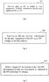
Fig. 1 is a flowchart (SN side) of an information management method provided by an embodiment of the present disclosure; -
Fig. 2 is a flowchart (MN side) of an information management method provided by an embodiment of the present disclosure; -
Fig. 3 is a flowchart of a secondary node changing method provided by an embodiment of the present disclosure; -
Fig. 4 is a block diagram of a node provided by an embodiment of the present disclosure; -
Fig. 5a is a schematic diagram of a control plane architecture in an EN-DC scenario provided by an embodiment of the present disclosure; -
Fig. 5b is a flowchart of the triggering of SN Change by an SN in an EN-DC scenario provided by an embodiment of the present disclosure; -
Fig. 6 is a flowchart of the triggering of SN Change by an SN in an MR-DC scenario connected with 5GC provided by an embodiment of the present disclosure; -
Fig. 7 is a flowchart of an MN handover with SN (SN unchanged) in an EN-DC scenario provided by an embodiment of the present disclosure; -
Fig. 8 is a flowchart of an MN handover with SN (SN changed) in an EN-DC scenario provided by an embodiment of the present disclosure; -
Fig. 9 is a block diagram of a node provided by an embodiment of the present disclosure; -
Fig. 10 is a block diagram of a computer-readable storage medium provided by an embodiment of the present disclosure; -
Fig. 11 is a block diagram of a node provided by another embodiment of the present disclosure; and -
Fig. 12 is a block diagram of a computer-readable storage medium provided by another embodiment of the present disclosure. - The embodiments of the present disclosure will be described below in combination with the accompanying drawings. Any combinations of embodiments and features of the embodiments of the present disclosure without conflict are possible.
- The steps shown in the flowcharts of the drawings may be performed in a computer system, such as with a set of computer-executable instructions. Moreover, although a logical order is shown in the flowcharts, the steps shown or described may be performed, in some cases, in a different order from that shown or described herein.
- In an embodiment of the present disclosure, there is provided an information management method applicable to dual connectivity systems, where the method is used to record and transmit history information for user equipment in an SpCell of a secondary cell group (PScell) on the SN side to assist in SN Change decision-making, so as to select a better target SN and enhance the robustness of the system.
- An embodiment of the present disclosure provides a managing method for history information for user equipment in a dual connectivity system, including the following steps: storing, by an SN, history information carried from an MN; recording history information in the current SN; bringing the history information in the SN to the MN; and selecting, by the SN, a target SN with reference to the history information to trigger an SN Change process.
- As shown in
Fig. 1 , an embodiment of the present disclosure provides an information management method, including the following step. - At
step 101, after an SN is added to user equipment (UE), the SN records history information for the user equipment. - At least one of the embodiments of the present disclosure provides an information management method, including the following step: after a secondary node is added to user equipment, the secondary node records the current history information for the user equipment. According to the scheme provided in this embodiment, the history information for the user equipment is recorded so as to facilitate subsequent use of the history information.
- Upon successful addition of the SN to the UE, the history information in a PScell is recorded by the SN, including history information after a PScell change due to PScellChange in this process, until the SN is changed or deleted.
- In an embodiment, the SN includes, but is not limited to, a Secondary gNodeB (SgNB) and a Secondary eNodeB (SeNB).
- In an embodiment, the content contained in the history information is consistent with that defined in the current protocol, including historical access cell information, which includes information such as cell system, cell identification, cell type, and residence time in the current cell. The current history information for the user equipment refers to the information for the user equipment in a residence cell under the current SN.
- In an embodiment, the method further includes the following step: in response to the SN receiving history information for the user equipment under other SNs sent by an MN, the history information for the user equipment under the other SNs is stored. In an embodiment, the SN is a target SN, and the MN initiates an SN Add process, at which time the MN carries the history information to the target SN through an SN Addition Request message.
- In an embodiment, the method further includes the following step: the SN sends the history information for the user equipment to the MN in an SN change or modify process. In an embodiment, the source SN carries the history information to the MN in an SN Change or SN Modify process, where in the SN Change process, the history information may be carried by an SN Change Required message; and in the SN Modify process, the history information may be carried by an SN Modification Request Acknowledge message.
- In an embodiment, the history information sent by the SN to the MN includes the history information for the user equipment recorded by the SN itself (including the history information for the user equipment under the secondary node and the history information for the user equipment before the secondary node being added), or includes the history information for the user equipment under the SN recorded by the SN itself and the history information for the user equipment under the other SNs received by the SN. The history information transmitted by the source SN includes history information carried from other MNs to the source SN and history information newly recorded by the source SN itself, which is the accumulation of history information. In an embodiment, in response to the number of pieces of the recorded history information exceeding a limited number, some records are deleted, for example, the oldest records are eliminated in order. The limited number may be set as required.
- As shown in
Fig. 2 , an embodiment of the present disclosure provides an information management method, including the following step. - At
step 201, the MN sends the history information for the user equipment to the SN in the SN change or modify process. - In an embodiment, the history information for the user equipment may be carried in an SN ADD request.
- In an embodiment, the MN acquires the history information for the user equipment from the source SN.
- In an embodiment, the MN sending the history information for the user equipment to the SN in the SN change or modify process includes the following step:
the MN sends the history information for the user equipment to a target SN in the SN change or modify process. - In an embodiment, the MN sending the history information for the user equipment to the secondary node in the secondary node change or modify process includes the following step:
the MN being a source MN, the source MN sends the history information for the user equipment to the target MN in the SN change or modify process, and the target MN sends the history information for the user equipment to the target SN. - As shown in
Fig. 3 , an embodiment of the present disclosure provides a secondary node changing method, including the following step. - At
step 301, in response to an SN initiating SN change, a target SN is selected according to history information for user equipment. - When the SN decides to initiate SN Change, it needs to select a target SN. At this moment, besides reference to signal quality, reference may be made to history information so as to select a better SN for change. According to the system implementation, a set of selection algorithms may be provided, for example, under the condition of equal signal quality, with reference to the residence time of the cell, an SN with longer residence time is selected as the target SN, etc., and the selection algorithm may be set as required, which is not limited in the present disclosure.
- In an embodiment, the method further includes the following step: the SN acquires the history information for the user equipment from the MN.
- In the scheme provided by this embodiment, by recording and transmitting the history information for the user equipment in the SN and referring to the history information when the SN initiates the SN Change decision-making, the target side of the SN Change is selected, thereby enhancing the robustness of the system.
- An embodiment of the present disclosure provides a
node 400 as shown inFig. 4 , which is a schematic diagram and does not limit the implementation of the node. When the node serves as the SN side under the dual connection, thenode 400 includes: arecording module 401. - The
recording module 401 is configured to be responsible for recording the history information in the current SN after the SN is successfully added, including the whole historical trajectory of changes of PScell in the SN. - In an embodiment, the
node 400 further includes a receivingmodule 402 and astorage module 403. - The receiving
module 402 is configured to receive the history information for the user equipment under the SN sent by the MN, where the history information may be carried in an SN Add request message. - The
storage module 403 is configured to store the history information for the user equipment under the SN. - In an embodiment, the
node 400 further includes: a sendingmodule 404 that is configured to send the history information for the UE to the MN when the SN initiates SN Change. For example, the history information is carried in an SN Change request message. - In an embodiment, the
node 400 further includes: a decision-making module 405 that is configured to make a decision according to the history information for the UE to determine the target SN when initiating SN Change, where a preset algorithm may be used to select an optimal target SN. - The present disclosure is illustrated below by several application examples.
- An embodiment of the present disclosure provides a secondary node changing method. This embodiment involves an EN-DC scenario, as shown in
Fig. 5a . In the EN-DC scenario, only the eNB (i.e., the MeNB inFig. 5a , the master node MN in this embodiment) has an S1-C signalling connection with the Evolved Packet Core (EPC), while the SgNB (the secondary node SN in this embodiment) has no signalling connection with the EPC. EN-DC related signalling is exchanged between the eNB and the gNB through X2-C. There is a signalling connection between the UE and the LTE for use in exchange of Radio Resource Control (RRC) signalling and Non-Access-Stratum (NAS) signalling. RRC signalling exchange with the SgNB may also be performed after the SgNB connection is successfully established. - As shown in
Fig. 5b , the following steps are included. - At step 501, upon successful access of the UE at the MN, the MN sends an SgNB Addition
- Request message to the SN (the source SN in this embodiment) to request the addition of the SN. Since it is the first time to add the SN, no history information for the SN is carried.
- At
step 502, the source SN replies to the MN with an SgNB Addition Request Acknowledge message to confirm the addition of the SN. - At step 503, upon successful reconfiguration of the UE at the MN side, the MN sends an SgNB Reconfiguration Complete message to the source SN to notify the source SN of the successful reconfiguration, and then the source SN may start recording the history information in the current PScell.
- At step 504, when the source SN initiates the SN Change process, there is no history information for reference (at this moment, there is only history information recorded by the source SN itself, but no history information from other SNs). The source SN sends an SgNB Change Required message to the MN to request SN Change, which carries the history information in PScell of the source SN.
- At
step 505, the MN sends an SgNB addition request message to the target SN to request the addition of the SN, which carries the history information in the source SN. - At
step 506, the target SN replies to the MN with an SgNB Addition Request Acknowledge message to confirm the addition of the SN. - At
step 507, the MN replies to the source SN with an SgNB Change Confirm message to confirm SN Change. - At step 508, upon successful reconfiguration of the UE at the MN side, the MN sends an SgNB Reconfiguration Complete message to the target SN to notify the target SN of the successful reconfiguration, and then the target SN may start recording the history information in the current PScell. When making subsequent decisions on SN Change, the target SN makes reference to the history information carried from the source SN, so as to select the next target SN, and carries the history information in the source SN (the history information acquired from the source SN) and the history information in the target SN (the history information recorded by the target SN) in the SgNB Change Required message sent by the target SN to the MN in the SN Change process.
- At
step 509, the MN sends a UE Context Release message to the source SN to notify the SN to release the UE context. - As shown in
Fig. 6 , an embodiment of the present disclosure provides an implementation of triggering SN Change by an SN in an MR-DC scene connected with 5GC, which includes the following steps. - At step 601, upon successful access of UE at an MN, the MN sends an SN Addition Request message to an SN (this SN is denoted as the source SN in this embodiment) to request the addition of the SN. Since it is the first time to add the SN, no history information for the SN is carried.
- At
step 602, the source SN replies to the MN with an SN Addition Request Acknowledge message to confirm the addition of the SN. - At step 603, upon successful reconfiguration of the UE at the MN side, the MN sends an SN Reconfiguration Complete message to the source SN to notify the source SN of the successful reconfiguration, and then the source SN may start recording the history information in the current PScell.
- At step 604, when the source SN initiates the SN Change process, there is no history information for reference (there is only the history information recorded by the source SN itself). The source SN sends an SN Change Required message to the MN to request SN Change, which carries the history information in the PScell of the source SN.
- At
step 605, the MN sends an SN Addition Request message to the target SN to request the addition of the SN, which carries the history information in the source SN. - At
step 606, the target SN replies to the MN with an SN Addition Request Acknowledge message to confirm the addition of the SN. - At
step 607, the MN replies to the source SN with an SN Change Confirm message to confirm SN Change. - At step 608, upon successful reconfiguration of the UE at the MN side, the MN sends an SN Reconfiguration Complete message to the target SN to notify the target SN of the successful reconfiguration, and then the target SN may start recording the history information in the current PScell. When making subsequent decisions on SN Change, the target SN makes reference to the history information carried from the source SN, so as to select the next target SN, and carries the history information in the source SN and in the target SN in the SN Change Required message sent by the target SN to the MN in the SN Change process.
- At
step 609, the MN sends a UE Context Release message to the source SN to notify the SN to release the UE context. - As shown in
Fig. 7 , the following steps are included. - At step 701, upon successful access of the UE at the MN (this MN is the source MN in this embodiment, which will be referred to as the source MN), the source MN sends an SgNB Addition Request message to the SN to request the addition of the SN. Since it is the first time to add the SN, no history information for the SN is carried.
- At
step 702, the SN replies to the source MN with an SgNB Addition Request Acknowledge message to confirm the addition of the SN. - At step 703, upon successful reconfiguration of the UE at the source MN side, the source MN sends an SgNB Reconfiguration Complete message to the SN to notify the SN of the successful reconfiguration, and then the SN may start recording the history information in the current PScell.
- At step 704, before the source MN initiates a handover, it needs to trigger the SN Modify process, and the source MN sends an SgNB Modification Request message to the SN to request SN configuration information.
- At
step 705, the SN replies to the source MN with an SgNB Modification Request Acknowledge message, which carries the history information in PScell of the SN. - At step 706, the source MN sends a Handover Request message to the target MN to initiate the handover, and the history information in the SN is carried in UE context information.
- At
step 707, the target MN initiates an SN addition process, and the target MN sends an SgNB Addition Request to the SN, which also carries the history information in the SN. - At
step 708, if the SN identifies the same UE and that PScell remains unchanged, it will continue to record the residence time in the current cell; otherwise, if PScell changes, it will rerecord the information in the new cell, and the SN will reply an SN Addition Request Acknowledge message to the target MN. - At
step 709, the target MN replies to the source MN with a Handover Request Acknowledge message. - At step 710, the source MN initiates the release preparation process of the SN, and the source MN sends an SgNB Release Request to the SN.
- At
step 711, the SN sends an SgNB Release Request Acknowledge message to the source MN. - At step 712, upon successful reconfiguration of the UE at the target MN side, the target MN sends an SN Reconfiguration Complete message to the SN to notify the SN of the successful reconfiguration.
- At
step 713, the target MN sends a UE Context Release message to the source MN to notify the source MN to initiate UE context release. - At
step 714, the source MN initiates UE context release of the SN, and the source MN sends a UE Context Release message to the SN. - As shown in
Fig. 8 , the following steps are included. - At step 801, upon successful access of the UE at the MN (which is referred to as the source MN in this embodiment), the source MN sends an SgNB Addition Request message to the SN (referred to as the source SN in the subsequent steps) to request the addition of the SN. Since it is the first time to add the SN, no history information for the SN is carried.
- At
step 802, the source SN replies to the source MN with an SgNB Addition Request Acknowledge message to confirm the addition of the SN. - At step 803, upon successful reconfiguration of the UE at the source MN side, the source MN sends an SgNB Reconfiguration Complete message to the source SN to notify the source SN of the successful reconfiguration, and then the source SN may start recording the history information in the current PScell.
- At
step 804, before the source MN initiates the handover, it needs to trigger the SN Modify process, and the source MN sends an SgNB Modification Request message to the source SN to request SN configuration information. - At
step 805, the source SN replies to the source MN with an SgNB Modification Request Acknowledge message, which carries the history information in PScell in the source SN. - At step 806, the source MN sends a Handover Request message to the target MN to initiate the handover, and the history information for the UE in the source SN is carried in UE context information.
- At
step 807, the target MN initiates an addition process to the target SN, and the target MN sends an SgNB Addition Request to the target SN, which also carries the history information in the source SN. - At
step 808, the target SN sends an SN Addition Request Acknowledge message to the target MN, and the target SN records the history information for the UE in the current SN. - At
step 809, the target MN replies to the source MN with a Handover Request Acknowledge message. - At
step 810, the source MN initiates the release preparation process of the source SN, and the source MN sends an SgNB Release Request to the source SN. - At
step 811, the source SN sends an SgNB Release Request Acknowledge message to the source MN. - At step 812, upon successful reconfiguration of the UE at the target MN side, the target MN sends an SN Reconfiguration Complete message to the target SN to notify the target SN of the successful reconfiguration.
- At
step 813, the target MN notifies the source MN to initiate UE context release, and the target MN sends a UE Context Release message to the source MN. - At
step 814, the source MN initiates UE context release of the source SN, and the source MN sends a UE Context Release message to the source SN. - As shown in
Fig. 9 , an embodiment of the present disclosure provides anode 90 including amemory 910 and aprocessor 920, where thememory 910 stores a program which, when read and executed by theprocessor 920, causes theprocessor 920 to perform an information management method according to any of the embodiments. - As shown in
Fig. 10 , an embodiment of the present disclosure provides a computer-readable storage medium 100, where the computer-readable storage medium 100 stores one ormore programs 1010, and the one ormore programs 1010 are executable by one or more processors to implement an information management method according to any of the embodiments. - As shown in
Fig. 11 , an embodiment of the present disclosure provides anode 110 including amemory 1110 and aprocessor 1120, where thememory 1110 stores a program which, when read and executed by theprocessor 1120, causes theprocessor 1120 to perform a secondary node changing method according to any of the embodiments. - As shown in
Fig. 12 , an embodiment of the present disclosure provides a computer-readable storage medium 120, where the computer-readable storage medium 120 stores one ormore programs 1210, and the one ormore programs 1210 are executable by one or more processors to implement a secondary node changing method according to any of the embodiments. - All or some of the steps of the methods, systems and functional modules/units in the devices disclosed above can be implemented as software, firmware, hardware and any appropriate combinations thereof. In the hardware implementation, the division between functional modules/units mentioned in the above description does not necessarily correspond to the division of physical components; for example, a physical component may have multiple functions, or a function or step may be performed cooperatively by a plurality of physical components. Some or all of the components may be implemented as software executed by a processor, such as a digital signal processor or a microprocessor, or as hardware, or as an integrated circuit, such as an application specific integrated circuit. Such software can be distributed on computer-readable media, which can include computer storage media (or non-transitory media) and communication media (or transitory media). Computer storage media include volatile and nonvolatile, removable and non-removable media implemented in any method or technology for storing information, such as computer-readable instructions, data structures, program modules or other data. The computer storage media include, but are not limited to, random access memory (RAM), read-only memory (ROM), electrically erasable programmable read-only memory (EEPROM), flash memory or other memory technologies, compact disc read-only memory (CD-ROM), digital versatile disk (DVD) or other optical disc storage, cassettes, magnetic tapes, magnetic disc storage or other magnetic storage devices, or any other media that can be configured to store desired information and can be accessed by computers. Communication media typically contain computer-readable instructions, data structures, program modules or other data in a modulated data signal such as a carrier wave or other transmission mechanism, and can include any information delivery media.
Claims (14)
- An information management method, comprising:
recording, after a secondary node is added to user equipment, history information for the user equipment by the secondary node. - The information management method of claim 1, further comprising:
storing, in response to the secondary node receiving history information for the user equipment under other secondary nodes sent by a master node, the history information for the user equipment under the other secondary nodes. - The information management method of claim 1, further comprising:
sending, by the secondary node, the history information for the user equipment to a master node, in a secondary node change or modify process. - The information management method of claim 3, wherein the history information sent by the secondary node to the master node comprises:the history information for the user equipment, which is recorded by the secondary node; orthe history information for the user equipment under the secondary node, which is recorded by the secondary node; and the history information for the user equipment under the other secondary nodes, which is received by the secondary node.
- An information management method, comprising:
sending, by a master node, history information for user equipment to a secondary node, in a secondary node change or modify process. - The information management method of claim 5, further comprising:
acquiring, by the master node, the history information for the user equipment, from a source secondary node. - The information management method of claim 5 or claim 6, wherein sending, by the master node, the history information for the user equipment to the secondary node in the secondary node change or modify process comprises:
sending, by the master node, the history information for the user equipment to a target secondary node, in the secondary node change or modify process. - The information management method of claim 5 or claim 6, wherein,the master node is a source master node; andsending, by the master node, the history information for the user equipment to the secondary node in the secondary node change or modify process comprises:sending, by the source master node, the history information for the user equipment to a target master node, in the secondary node change or modify process, andsending, by the target master node, the history information for the user equipment to a target secondary node.
- A secondary node changing method, comprising:
selecting, in response to a secondary node initiating secondary node change, a target secondary node according to history information for user equipment. - The secondary node changing method of claim 9, further comprising: acquiring, by the secondary node, the history information for the user equipment from a master node.
- Anode comprising a memory and a processor, wherein the memory stores a program which, when read and executed by the processor, causes the processor to perform an information management method of any one of claims 1 to 8.
- A computer-readable storage medium, wherein the computer-readable storage medium stores one or more programs which are executable by one or more processors to implement an information management method of any one of claims 1 to 8.
- A node comprising a memory and a processor, wherein the memory stores a program which, when read and executed by the processor, causes the processor to perform a secondary node changing method of claim 9 or claim 10.
- A computer-readable storage medium, wherein the computer-readable storage medium stores one or more programs which are executable by one or more processors to implement a secondary node changing method of claim 9 or claim 10.
Applications Claiming Priority (2)
| Application Number | Priority Date | Filing Date | Title |
|---|---|---|---|
| CN201910550193.0A CN112135332A (en) | 2019-06-24 | 2019-06-24 | Information management method, auxiliary node changing method, node, and storage medium |
| PCT/CN2020/097420 WO2020259435A1 (en) | 2019-06-24 | 2020-06-22 | Information management method, secondary node changing method, node, and storage medium |
Publications (3)
| Publication Number | Publication Date |
|---|---|
| EP3986030A1 true EP3986030A1 (en) | 2022-04-20 |
| EP3986030A4 EP3986030A4 (en) | 2022-08-03 |
| EP3986030B1 EP3986030B1 (en) | 2024-10-09 |
Family
ID=73849627
Family Applications (1)
| Application Number | Title | Priority Date | Filing Date |
|---|---|---|---|
| EP20830934.4A Active EP3986030B1 (en) | 2019-06-24 | 2020-06-22 | Information management method, secondary node changing method, node, and storage medium |
Country Status (6)
| Country | Link |
|---|---|
| US (1) | US12512944B2 (en) |
| EP (1) | EP3986030B1 (en) |
| JP (1) | JP7308305B2 (en) |
| KR (1) | KR102759849B1 (en) |
| CN (1) | CN112135332A (en) |
| WO (1) | WO2020259435A1 (en) |
Families Citing this family (7)
| Publication number | Priority date | Publication date | Assignee | Title |
|---|---|---|---|---|
| CN112399495B (en) * | 2019-08-15 | 2022-11-18 | 华为技术有限公司 | Method and device for recording historical information and computer readable storage medium |
| CN116963230A (en) * | 2020-08-17 | 2023-10-27 | 瑞典爱立信有限公司 | Method and apparatus for cell selection in non-terrestrial networks (NTNs) |
| US20240306048A1 (en) * | 2021-01-08 | 2024-09-12 | Nec Corporation | Method, device and computer storage medium of communication |
| US20240306049A1 (en) * | 2021-01-14 | 2024-09-12 | Lenovo (Beijing) Limited | Method and apparatus for performing pscell change procedure |
| KR102745769B1 (en) | 2022-01-26 | 2024-12-20 | 주식회사 엘지에너지솔루션 | Apparatus and method for estimating state of charge of battery |
| US20250280345A1 (en) * | 2022-04-27 | 2025-09-04 | Beijing Xiaomi Mobile Software Co., Ltd. | Method for recording relevant information of successful pscell addition or change report |
| CN118354373A (en) * | 2023-01-06 | 2024-07-16 | 展讯通信(上海)有限公司 | Communication method and device, terminal equipment, main node and auxiliary node |
Family Cites Families (34)
| Publication number | Priority date | Publication date | Assignee | Title |
|---|---|---|---|---|
| EP2425551B1 (en) * | 2009-04-28 | 2019-08-14 | Samsung Electronics Co., Ltd. | Method and apparatus for managing user equipment history information in wireless communication network |
| CN102769877B (en) * | 2011-05-04 | 2017-08-25 | 中兴通讯股份有限公司 | Cell switching method and base station |
| CN108934077B (en) * | 2012-10-05 | 2024-02-23 | 日本电气株式会社 | Radio station, radio terminal and method thereof |
| KR102033978B1 (en) * | 2012-10-05 | 2019-10-18 | 닛본 덴끼 가부시끼가이샤 | Wireless communication system, wireless station, wireless terminal, network device, bearer control method, and computer-readable medium |
| CN104244318A (en) * | 2013-06-08 | 2014-12-24 | 株式会社Ntt都科摩 | Method and device for adjusting time to trigger |
| WO2014198316A1 (en) * | 2013-06-13 | 2014-12-18 | Telefonaktiebolaget L M Ericsson (Publ) | Determination of radio resource usage |
| KR102151533B1 (en) * | 2013-10-18 | 2020-09-03 | 에스케이텔레콤 주식회사 | Apparatus for delivering cell history information in wireless communication system and method thereof |
| EP3063966B1 (en) * | 2013-11-01 | 2019-03-06 | LG Electronics Inc. | Method for transmitting cell visited history and wireless equipment thereof |
| CN104811924B (en) * | 2014-01-24 | 2018-07-13 | 上海诺基亚贝尔股份有限公司 | The management method of user equipment historical information for doubly-linked welding system |
| EP2903386A1 (en) * | 2014-01-29 | 2015-08-05 | Alcatel Lucent | Methode and device for establishing a dual connectivity between a user equipment and a MeNB and a SeNB, by providing the user equipment history information |
| JP2015177424A (en) * | 2014-03-17 | 2015-10-05 | 株式会社Kddi研究所 | Base station apparatus, terminal apparatus, communication system, and communication method |
| PL2983439T3 (en) * | 2014-08-06 | 2021-05-31 | Alcatel Lucent | Special cell selection at secondary network nodes supporting dual connectivity |
| EP4221055A1 (en) * | 2014-08-06 | 2023-08-02 | Mitsubishi Electric Corporation | Mobile communication system, user equipment and base station |
| WO2016163544A1 (en) * | 2015-04-10 | 2016-10-13 | 京セラ株式会社 | Method for controlling handover procedure and base station |
| CN106658719B (en) * | 2015-10-30 | 2019-12-17 | 中国电信股份有限公司 | Data distribution method and device |
| WO2017130852A1 (en) * | 2016-01-25 | 2017-08-03 | 京セラ株式会社 | Wireless terminal and base station |
| GB2550212A (en) * | 2016-05-13 | 2017-11-15 | Nec Corp | Communication system |
| WO2018030841A1 (en) * | 2016-08-11 | 2018-02-15 | 엘지전자 주식회사 | Method for reporting reference signal measurement information by terminal in wireless communication system, and apparatus supporting same |
| EP3552428A1 (en) * | 2016-12-12 | 2019-10-16 | Telefonaktiebolaget LM Ericsson (publ) | Network node and method for communicating with a wireless device using channel quality of scell |
| US11006359B2 (en) * | 2016-12-23 | 2021-05-11 | Telefonaktiebolaget Lm Ericsson (Publ) | Method and nodes for enabling a wireless terminal configured with dual connectivity to enter an inactive mode |
| CN108282836B (en) * | 2017-01-06 | 2020-10-30 | 展讯通信(上海)有限公司 | Secondary base station handover method, device and base station |
| EP3589069B1 (en) * | 2017-03-25 | 2021-09-01 | LG Electronics Inc. | Method and apparatus for improving procedure for lte/nr interworking in wireless communication system |
| KR102388500B1 (en) * | 2017-06-15 | 2022-04-21 | 삼성전자 주식회사 | Method and apparatus for handling mobility in dual rrc system |
| EP3453221B1 (en) * | 2017-06-16 | 2020-01-22 | Telefonaktiebolaget LM Ericsson (publ.) | Race condition avoidance between master base station initiated secondary base station release and secondary base station initiated secondary base station change procedures |
| WO2019074429A1 (en) * | 2017-10-09 | 2019-04-18 | Telefonaktiebolaget Lm Ericsson (Publ) | A master node, a secondary node and methods performed therein |
| RU2745330C1 (en) * | 2017-11-16 | 2021-03-24 | Телефонактиеболагет Лм Эрикссон (Пабл) | TEID EXCHANGE BETWEEN DU AND CP-UP IN gNB |
| EP3544367B1 (en) * | 2018-03-11 | 2022-08-10 | HTC Corporation | Device and method of handling a secondary node configuration |
| CN110519748B (en) * | 2018-05-21 | 2021-07-02 | 大唐移动通信设备有限公司 | Close coupling processing method, device and base station |
| EP3915316A4 (en) * | 2019-01-25 | 2022-10-12 | QUALCOMM Incorporated | SECONDARY CELL GROUP CONFIGURATION IN THE DUAL CONNECTIVITY OF A MULTIRADIO ACCESS TECHNOLOGY AND CARRIER AGGREGATION |
| US11895720B2 (en) * | 2019-02-14 | 2024-02-06 | Nokia Technologies Oy | Control mechanism for supporting connection establishment procedure |
| CN111866963B (en) * | 2019-04-28 | 2021-12-31 | 华为技术有限公司 | Communication method, communication device, computer storage medium, and communication system |
| CN113796118B (en) * | 2019-05-10 | 2023-11-24 | Oppo广东移动通信有限公司 | Switching method and device and communication equipment |
| CN112399495B (en) * | 2019-08-15 | 2022-11-18 | 华为技术有限公司 | Method and device for recording historical information and computer readable storage medium |
| WO2021064692A1 (en) * | 2019-10-03 | 2021-04-08 | Telefonaktiebolaget Lm Ericsson (Publ) | Enhancements in mobility history information |
-
2019
- 2019-06-24 CN CN201910550193.0A patent/CN112135332A/en active Pending
-
2020
- 2020-06-22 EP EP20830934.4A patent/EP3986030B1/en active Active
- 2020-06-22 KR KR1020217042353A patent/KR102759849B1/en active Active
- 2020-06-22 WO PCT/CN2020/097420 patent/WO2020259435A1/en not_active Ceased
- 2020-06-22 US US17/622,510 patent/US12512944B2/en active Active
- 2020-06-22 JP JP2021577159A patent/JP7308305B2/en active Active
Also Published As
| Publication number | Publication date |
|---|---|
| EP3986030A4 (en) | 2022-08-03 |
| JP7308305B2 (en) | 2023-07-13 |
| WO2020259435A1 (en) | 2020-12-30 |
| KR20220011728A (en) | 2022-01-28 |
| EP3986030B1 (en) | 2024-10-09 |
| US12512944B2 (en) | 2025-12-30 |
| KR102759849B1 (en) | 2025-01-24 |
| JP2022539745A (en) | 2022-09-13 |
| US20220248294A1 (en) | 2022-08-04 |
| CN112135332A (en) | 2020-12-25 |
Similar Documents
| Publication | Publication Date | Title |
|---|---|---|
| US12512944B2 (en) | Information management method, secondary node changing method, node, and storage medium | |
| EP3681221B1 (en) | Method and device for configuring cell in wireless communication system | |
| US12532362B2 (en) | Systems and methods for reporting random access information in wireless communication networks | |
| US20220279403A1 (en) | Information transmission method and apparatus, storage medium and electronic apparatus | |
| EP3606222B1 (en) | Radio resource configuration method and device, user equipment and network element | |
| US20230262588A1 (en) | Cell configuration schemes in wireless communications | |
| KR20160048177A (en) | Method and system for random access procedure and radio link failure in inter-enb carrier aggregation | |
| CN113518473A (en) | Enhanced reporting of random access channels | |
| WO2016072047A1 (en) | Wireless terminal, wireless station, and methods for same | |
| CN108990101B (en) | Apparatus and method for processing secondary node change in dual connectivity | |
| CN112788672B (en) | Secondary base station changing method, main base station, secondary base station and terminal | |
| EP4443963A1 (en) | Timing advance acquisition, management, and reporting | |
| US20240340946A1 (en) | Timing advance resource management | |
| CN115190640A (en) | Communication method and communication device | |
| EP4460116B1 (en) | Requesting timing advance acquisition for other cells | |
| CN117098176A (en) | Communication methods and devices | |
| CN110049577B (en) | Method and device for reestablishing Radio Resource Control (RRC) | |
| US20250081075A1 (en) | Ltm failure handling using a fallback configuration for one of a radio link failure (rlf) or a handover (ho) failure of a user equipment (ue) | |
| US11910448B2 (en) | Random access channel preamble assignments for dual connectivity | |
| GB2634306A (en) | Switch to RRC connected state | |
| CN121646976A (en) | LTM configuration timer and user plane path switching | |
| CN118509878A (en) | Communication method and device |
Legal Events
| Date | Code | Title | Description |
|---|---|---|---|
| STAA | Information on the status of an ep patent application or granted ep patent |
Free format text: STATUS: THE INTERNATIONAL PUBLICATION HAS BEEN MADE |
|
| PUAI | Public reference made under article 153(3) epc to a published international application that has entered the european phase |
Free format text: ORIGINAL CODE: 0009012 |
|
| STAA | Information on the status of an ep patent application or granted ep patent |
Free format text: STATUS: REQUEST FOR EXAMINATION WAS MADE |
|
| 17P | Request for examination filed |
Effective date: 20220112 |
|
| AK | Designated contracting states |
Kind code of ref document: A1 Designated state(s): AL AT BE BG CH CY CZ DE DK EE ES FI FR GB GR HR HU IE IS IT LI LT LU LV MC MK MT NL NO PL PT RO RS SE SI SK SM TR |
|
| A4 | Supplementary search report drawn up and despatched |
Effective date: 20220701 |
|
| RIC1 | Information provided on ipc code assigned before grant |
Ipc: H04W 76/15 20180101ALI20220627BHEP Ipc: H04W 36/24 20090101ALI20220627BHEP Ipc: H04W 36/00 20090101AFI20220627BHEP |
|
| DAV | Request for validation of the european patent (deleted) | ||
| DAX | Request for extension of the european patent (deleted) | ||
| REG | Reference to a national code |
Ref country code: DE Ref legal event code: R079 Free format text: PREVIOUS MAIN CLASS: H04W0048160000 Ipc: H04W0036000000 Ref country code: DE Ref legal event code: R079 Ref document number: 602020039248 Country of ref document: DE Free format text: PREVIOUS MAIN CLASS: H04W0048160000 Ipc: H04W0036000000 |
|
| GRAP | Despatch of communication of intention to grant a patent |
Free format text: ORIGINAL CODE: EPIDOSNIGR1 |
|
| STAA | Information on the status of an ep patent application or granted ep patent |
Free format text: STATUS: GRANT OF PATENT IS INTENDED |
|
| RIC1 | Information provided on ipc code assigned before grant |
Ipc: H04W 92/20 20090101ALN20240531BHEP Ipc: H04W 76/15 20180101ALN20240531BHEP Ipc: H04W 36/08 20090101ALI20240531BHEP Ipc: H04W 36/00 20090101AFI20240531BHEP |
|
| RIC1 | Information provided on ipc code assigned before grant |
Ipc: H04W 92/20 20090101ALN20240607BHEP Ipc: H04W 76/15 20180101ALN20240607BHEP Ipc: H04W 36/08 20090101ALI20240607BHEP Ipc: H04W 36/00 20090101AFI20240607BHEP |
|
| INTG | Intention to grant announced |
Effective date: 20240709 |
|
| GRAS | Grant fee paid |
Free format text: ORIGINAL CODE: EPIDOSNIGR3 |
|
| GRAA | (expected) grant |
Free format text: ORIGINAL CODE: 0009210 |
|
| STAA | Information on the status of an ep patent application or granted ep patent |
Free format text: STATUS: THE PATENT HAS BEEN GRANTED |
|
| AK | Designated contracting states |
Kind code of ref document: B1 Designated state(s): AL AT BE BG CH CY CZ DE DK EE ES FI FR GB GR HR HU IE IS IT LI LT LU LV MC MK MT NL NO PL PT RO RS SE SI SK SM TR |
|
| REG | Reference to a national code |
Ref country code: CH Ref legal event code: EP |
|
| REG | Reference to a national code |
Ref country code: DE Ref legal event code: R096 Ref document number: 602020039248 Country of ref document: DE |
|
| REG | Reference to a national code |
Ref country code: IE Ref legal event code: FG4D |
|
| REG | Reference to a national code |
Ref country code: LT Ref legal event code: MG9D |
|
| REG | Reference to a national code |
Ref country code: NL Ref legal event code: MP Effective date: 20241009 |
|
| REG | Reference to a national code |
Ref country code: AT Ref legal event code: MK05 Ref document number: 1731972 Country of ref document: AT Kind code of ref document: T Effective date: 20241009 |
|
| PG25 | Lapsed in a contracting state [announced via postgrant information from national office to epo] |
Ref country code: NL Free format text: LAPSE BECAUSE OF FAILURE TO SUBMIT A TRANSLATION OF THE DESCRIPTION OR TO PAY THE FEE WITHIN THE PRESCRIBED TIME-LIMIT Effective date: 20241009 |
|
| PG25 | Lapsed in a contracting state [announced via postgrant information from national office to epo] |
Ref country code: NL Free format text: LAPSE BECAUSE OF FAILURE TO SUBMIT A TRANSLATION OF THE DESCRIPTION OR TO PAY THE FEE WITHIN THE PRESCRIBED TIME-LIMIT Effective date: 20241009 |
|
| PG25 | Lapsed in a contracting state [announced via postgrant information from national office to epo] |
Ref country code: PT Free format text: LAPSE BECAUSE OF FAILURE TO SUBMIT A TRANSLATION OF THE DESCRIPTION OR TO PAY THE FEE WITHIN THE PRESCRIBED TIME-LIMIT Effective date: 20250210 Ref country code: IS Free format text: LAPSE BECAUSE OF FAILURE TO SUBMIT A TRANSLATION OF THE DESCRIPTION OR TO PAY THE FEE WITHIN THE PRESCRIBED TIME-LIMIT Effective date: 20250209 Ref country code: HR Free format text: LAPSE BECAUSE OF FAILURE TO SUBMIT A TRANSLATION OF THE DESCRIPTION OR TO PAY THE FEE WITHIN THE PRESCRIBED TIME-LIMIT Effective date: 20241009 |
|
| PG25 | Lapsed in a contracting state [announced via postgrant information from national office to epo] |
Ref country code: FI Free format text: LAPSE BECAUSE OF FAILURE TO SUBMIT A TRANSLATION OF THE DESCRIPTION OR TO PAY THE FEE WITHIN THE PRESCRIBED TIME-LIMIT Effective date: 20241009 |
|
| PG25 | Lapsed in a contracting state [announced via postgrant information from national office to epo] |
Ref country code: BG Free format text: LAPSE BECAUSE OF FAILURE TO SUBMIT A TRANSLATION OF THE DESCRIPTION OR TO PAY THE FEE WITHIN THE PRESCRIBED TIME-LIMIT Effective date: 20241009 |
|
| PG25 | Lapsed in a contracting state [announced via postgrant information from national office to epo] |
Ref country code: ES Free format text: LAPSE BECAUSE OF FAILURE TO SUBMIT A TRANSLATION OF THE DESCRIPTION OR TO PAY THE FEE WITHIN THE PRESCRIBED TIME-LIMIT Effective date: 20241009 |
|
| PG25 | Lapsed in a contracting state [announced via postgrant information from national office to epo] |
Ref country code: NO Free format text: LAPSE BECAUSE OF FAILURE TO SUBMIT A TRANSLATION OF THE DESCRIPTION OR TO PAY THE FEE WITHIN THE PRESCRIBED TIME-LIMIT Effective date: 20250109 |
|
| PG25 | Lapsed in a contracting state [announced via postgrant information from national office to epo] |
Ref country code: LV Free format text: LAPSE BECAUSE OF FAILURE TO SUBMIT A TRANSLATION OF THE DESCRIPTION OR TO PAY THE FEE WITHIN THE PRESCRIBED TIME-LIMIT Effective date: 20241009 Ref country code: GR Free format text: LAPSE BECAUSE OF FAILURE TO SUBMIT A TRANSLATION OF THE DESCRIPTION OR TO PAY THE FEE WITHIN THE PRESCRIBED TIME-LIMIT Effective date: 20250110 Ref country code: AT Free format text: LAPSE BECAUSE OF FAILURE TO SUBMIT A TRANSLATION OF THE DESCRIPTION OR TO PAY THE FEE WITHIN THE PRESCRIBED TIME-LIMIT Effective date: 20241009 |
|
| PG25 | Lapsed in a contracting state [announced via postgrant information from national office to epo] |
Ref country code: PL Free format text: LAPSE BECAUSE OF FAILURE TO SUBMIT A TRANSLATION OF THE DESCRIPTION OR TO PAY THE FEE WITHIN THE PRESCRIBED TIME-LIMIT Effective date: 20241009 |
|
| PG25 | Lapsed in a contracting state [announced via postgrant information from national office to epo] |
Ref country code: RS Free format text: LAPSE BECAUSE OF FAILURE TO SUBMIT A TRANSLATION OF THE DESCRIPTION OR TO PAY THE FEE WITHIN THE PRESCRIBED TIME-LIMIT Effective date: 20250109 |
|
| PG25 | Lapsed in a contracting state [announced via postgrant information from national office to epo] |
Ref country code: SM Free format text: LAPSE BECAUSE OF FAILURE TO SUBMIT A TRANSLATION OF THE DESCRIPTION OR TO PAY THE FEE WITHIN THE PRESCRIBED TIME-LIMIT Effective date: 20241009 |
|
| PGFP | Annual fee paid to national office [announced via postgrant information from national office to epo] |
Ref country code: DE Payment date: 20250618 Year of fee payment: 6 |
|
| PG25 | Lapsed in a contracting state [announced via postgrant information from national office to epo] |
Ref country code: DK Free format text: LAPSE BECAUSE OF FAILURE TO SUBMIT A TRANSLATION OF THE DESCRIPTION OR TO PAY THE FEE WITHIN THE PRESCRIBED TIME-LIMIT Effective date: 20241009 |
|
| PGFP | Annual fee paid to national office [announced via postgrant information from national office to epo] |
Ref country code: GB Payment date: 20250618 Year of fee payment: 6 |
|
| REG | Reference to a national code |
Ref country code: DE Ref legal event code: R097 Ref document number: 602020039248 Country of ref document: DE |
|
| PG25 | Lapsed in a contracting state [announced via postgrant information from national office to epo] |
Ref country code: EE Free format text: LAPSE BECAUSE OF FAILURE TO SUBMIT A TRANSLATION OF THE DESCRIPTION OR TO PAY THE FEE WITHIN THE PRESCRIBED TIME-LIMIT Effective date: 20241009 |
|
| PGFP | Annual fee paid to national office [announced via postgrant information from national office to epo] |
Ref country code: FR Payment date: 20250627 Year of fee payment: 6 |
|
| PG25 | Lapsed in a contracting state [announced via postgrant information from national office to epo] |
Ref country code: RO Free format text: LAPSE BECAUSE OF FAILURE TO SUBMIT A TRANSLATION OF THE DESCRIPTION OR TO PAY THE FEE WITHIN THE PRESCRIBED TIME-LIMIT Effective date: 20241009 |
|
| PG25 | Lapsed in a contracting state [announced via postgrant information from national office to epo] |
Ref country code: SK Free format text: LAPSE BECAUSE OF FAILURE TO SUBMIT A TRANSLATION OF THE DESCRIPTION OR TO PAY THE FEE WITHIN THE PRESCRIBED TIME-LIMIT Effective date: 20241009 |
|
| PG25 | Lapsed in a contracting state [announced via postgrant information from national office to epo] |
Ref country code: CZ Free format text: LAPSE BECAUSE OF FAILURE TO SUBMIT A TRANSLATION OF THE DESCRIPTION OR TO PAY THE FEE WITHIN THE PRESCRIBED TIME-LIMIT Effective date: 20241009 |
|
| PG25 | Lapsed in a contracting state [announced via postgrant information from national office to epo] |
Ref country code: IT Free format text: LAPSE BECAUSE OF FAILURE TO SUBMIT A TRANSLATION OF THE DESCRIPTION OR TO PAY THE FEE WITHIN THE PRESCRIBED TIME-LIMIT Effective date: 20241009 |
|
| PLBE | No opposition filed within time limit |
Free format text: ORIGINAL CODE: 0009261 |
|
| STAA | Information on the status of an ep patent application or granted ep patent |
Free format text: STATUS: NO OPPOSITION FILED WITHIN TIME LIMIT |
|
| PG25 | Lapsed in a contracting state [announced via postgrant information from national office to epo] |
Ref country code: SE Free format text: LAPSE BECAUSE OF FAILURE TO SUBMIT A TRANSLATION OF THE DESCRIPTION OR TO PAY THE FEE WITHIN THE PRESCRIBED TIME-LIMIT Effective date: 20241009 |
|
| 26N | No opposition filed |
Effective date: 20250710 |
|
| REG | Reference to a national code |
Ref country code: CH Ref legal event code: H13 Free format text: ST27 STATUS EVENT CODE: U-0-0-H10-H13 (AS PROVIDED BY THE NATIONAL OFFICE) Effective date: 20260127 |
|
| PG25 | Lapsed in a contracting state [announced via postgrant information from national office to epo] |
Ref country code: MC Free format text: LAPSE BECAUSE OF FAILURE TO SUBMIT A TRANSLATION OF THE DESCRIPTION OR TO PAY THE FEE WITHIN THE PRESCRIBED TIME-LIMIT Effective date: 20241009 |
|
| PG25 | Lapsed in a contracting state [announced via postgrant information from national office to epo] |
Ref country code: LU Free format text: LAPSE BECAUSE OF NON-PAYMENT OF DUE FEES Effective date: 20250622 |
|
| REG | Reference to a national code |
Ref country code: BE Ref legal event code: MM Effective date: 20250630 |
|
| PG25 | Lapsed in a contracting state [announced via postgrant information from national office to epo] |
Ref country code: IE Free format text: LAPSE BECAUSE OF NON-PAYMENT OF DUE FEES Effective date: 20250622 |
|
| PG25 | Lapsed in a contracting state [announced via postgrant information from national office to epo] |
Ref country code: BE Free format text: LAPSE BECAUSE OF NON-PAYMENT OF DUE FEES Effective date: 20250630 |
|
| PG25 | Lapsed in a contracting state [announced via postgrant information from national office to epo] |
Ref country code: CH Free format text: LAPSE BECAUSE OF NON-PAYMENT OF DUE FEES Effective date: 20250630 |