EP3985998B1 - Method for configuring a digital audio filter, digital audio filter, and sound system - Google Patents
Method for configuring a digital audio filter, digital audio filter, and sound system Download PDFInfo
- Publication number
- EP3985998B1 EP3985998B1 EP20202571.4A EP20202571A EP3985998B1 EP 3985998 B1 EP3985998 B1 EP 3985998B1 EP 20202571 A EP20202571 A EP 20202571A EP 3985998 B1 EP3985998 B1 EP 3985998B1
- Authority
- EP
- European Patent Office
- Prior art keywords
- digital audio
- impulse response
- audio filter
- subset
- poles
- Prior art date
- Legal status (The legal status is an assumption and is not a legal conclusion. Google has not performed a legal analysis and makes no representation as to the accuracy of the status listed.)
- Active
Links
Images


Classifications
-
- H—ELECTRICITY
- H04—ELECTRIC COMMUNICATION TECHNIQUE
- H04S—STEREOPHONIC SYSTEMS
- H04S7/00—Indicating arrangements; Control arrangements, e.g. balance control
- H04S7/30—Control circuits for electronic adaptation of the sound field
- H04S7/305—Electronic adaptation of stereophonic audio signals to reverberation of the listening space
-
- H—ELECTRICITY
- H04—ELECTRIC COMMUNICATION TECHNIQUE
- H04R—LOUDSPEAKERS, MICROPHONES, GRAMOPHONE PICK-UPS OR LIKE ACOUSTIC ELECTROMECHANICAL TRANSDUCERS; ELECTRIC HEARING AIDS; PUBLIC ADDRESS SYSTEMS
- H04R2499/00—Aspects covered by H04R or H04S not otherwise provided for in their subgroups
- H04R2499/10—General applications
- H04R2499/13—Acoustic transducers and sound field adaptation in vehicles
-
- H—ELECTRICITY
- H04—ELECTRIC COMMUNICATION TECHNIQUE
- H04R—LOUDSPEAKERS, MICROPHONES, GRAMOPHONE PICK-UPS OR LIKE ACOUSTIC ELECTROMECHANICAL TRANSDUCERS; ELECTRIC HEARING AIDS; PUBLIC ADDRESS SYSTEMS
- H04R3/00—Circuits for transducers
Definitions
- the present invention is in the field of digital filtering of audio signals.
- the present invention is in the field of configuring a digital audio filter for a pleasing sound experience.
- Modern digital audio filters have become more and more complex.
- One reason for the increasing complexity is the aim to compensate for the room acoustics in a listening position. Attempts to adapt an audio output to a particular auditory space by compensating for auditory space artifacts may lead to complex digital audio filters.
- the complex signal processing may make it difficult to have good control over the filter characteristics.
- it may be difficult to manipulate the filter characteristics in a highly targeted manner.
- manipulations in the time domain or in the frequency domain may have undesirably broad effects in the respectively other domain. This in turn may lead to undesired degradations of the sound experience for a listener.
- Exemplary embodiments of the invention include a method for configuring a digital audio filter in accordance with claim 1 and a vehicle sound system in accordance with claim 11. Further embodiments of the invention are given in the dependent claims.
- Exemplary embodiments of the invention include a method for configuring a digital audio filter, comprising: providing a decaying impulse response in the time domain, representing at least part of the transfer characteristics of the digital audio filter; determining the poles and zeros of the decaying impulse response in the z-domain; selecting at least one subset of the poles and zeros of the decaying impulse response; and, for each of the at least one subset of the poles and zeros: determining a respective subset impulse response in the time domain, windowing the respective subset impulse response in the time domain, and configuring the digital audio filter in accordance with the windowed respective subset impulse response.
- Exemplary embodiments of the invention allow for manipulating the transfer characteristics of a digital audio filter in a manner that is highly targeted both in the time domain and the frequency domain.
- a subset impulse response i.e. an impulse response associated with the subset of the poles and zeros selected
- the manipulation may be highly targeted in the frequency domain.
- a highly targeted manipulation in the time domain may be achieved.
- the method in accordance with exemplary embodiments of the invention may allow for a particularly good trade-off in controlling the transfer characteristics of the digital audio filter in the time domain and the frequency domain.
- the method comprises the step of providing a decaying impulse response in the time domain, representing at least part of the transfer characteristics of the digital audio filter.
- the expression providing a decaying impulse response in the time domain may refer to determining a desired decaying impulse response in the time domain on the basis of desired impulse response characteristics. It may also refer to determining the decaying impulse response from another representation of the transfer characteristics of the digital audio filter, such as from a transfer function in the frequency domain.
- the expression may also refer to accessing a decaying impulse response in the time domain that is readily accessable, such as from a previously determined initial configuration / set-up of the digital audio filter.
- the expression of representing at least part of the transfer characteristics of the digital audio filter means that the decaying impulse response represents part of the transfer characteristics of an initial set-up of the digital audio filter, i.e. a set-up of the digital audio filter before the ensuing method steps are carried out.
- the decaying impulse response may represent part of the transfer characteristics of the digital audio filter or all of the transfer characteristics of the digital audio filter.
- exemplary embodiments of the invention relate to a method for configuring a digital audio filter.
- the method for configuring a digital audio filter may also be referred to as a method for adapting an initial set-up of the digital audio filter and forming a modified set-up of the digital audio filter.
- the decaying impulse response may represent at least part of the initial set-up of the digital audio filter, with the ensuing method steps manipulating set decaying impulse response and, thus, resulting in a modified set-up of the digital audio filter.
- the modified set-up of the digital audio filter may be a final set-up of the digital audio filter or may be subject to further modifications.
- the method comprises selecting at least one subset of the poles and zeros of the decaying impulse response.
- the term subset may refer to any subset of the total set of poles and zeros.
- the subset may comprise one, two, three, four, five, six, seven, eight, nine, ten or more poles/zeros.
- the subset may comprise only poles or only zeros or a combination of poles and zeros.
- the one or more subsets may be selected in accordance with various criteria, as will be laid out in more detail below.
- the method comprises determining a respective subset impulse response in the time domain for a given subset of the poles and zeros.
- subset impulse response refers to an impulse response of a transfer function that is determined by the given subset of the poles and zeros.
- the given subset of the poles and zeros determine transfer characteristics in the frequency domain, with the subset impulse response representing said transfer characteristics in the time domain.
- the method comprises windowing the subset impulse response in the time domain.
- the windowing is a manipulation of the subset impulse response in the time domain.
- the windowing may be performed with a variety of different windows, as will be laid out below.
- the windowing may include a weighing of individual values in the subset impulse response, depending on their position along the time axis, and/or a clipping of the subset impulse response in the time domain.
- the windowing of the respective subset impulse response in the time domain yields a windowed respective subset impulse response. While the term respective subset impulse response refers to a component of the transfer characteristics of the initial set-up of the digital audio filter, the term windowed respective subset impulse response refers to a component of the modified set-up of the digital audio filter.
- the method includes configuring the digital audio filter in accordance with the windowed subset impulse response.
- Said configuring of the digital audio filter may also be viewed as using the windowed subset impulse response in the digital audio filter, instead of the un-windowed subset impulse response, i.e. instead of the subset impulse response that is the result of the step of determining a subset impulse response in the time domain.
- the step of configuring the digital audio filter in accordance with the windowed respective subset impulse response may be viewed as replacing that part of the decaying impulse response that is associated with the subset of the poles and zeros in question with the windowed respective subset impulse response. In this way, the decaying impulse response may be manipulated in a highly targeted manner, depending on the particular selection of the subset of the poles and zeros.
- the step of selecting at least one subset of the poles and zeros of the decaying impulse response comprises: grouping poles and zeros of the decaying impulse response in accordance with at least one predefined frequency interval.
- the selecting of the at least one subset of the poles and zeros may comprise checking if and how many poles and zeros are within one or more predefined frequency intervals and combining those poles and zeros within the one or more predefined frequency intervals, if present, into said at least one subset of the poles and zeros.
- the step of selecting at least one subset of the poles and zeros may provide an effective means for targeting certain frequency intervals for manipulation, while maintaining a manageable level of complexity by grouping the poles and zeros in accordance with the one or more predefined frequency intervals.
- the predefined frequency intervals may span the whole audible range from about 20 Hz to about 20 kHz or may span one or more portions thereof.
- said grouping of poles and zeros in accordance with at least one predefined frequency interval comprises grouping poles and zeros in accordance with between 5 and 30 predefined frequency intervals.
- it may comprise grouping poles and zeros in accordance with between 10 and 20 predefined frequency intervals.
- it may comprise grouping poles and zeros in accordance with 15 predefined frequency intervals. It has been found that said numbers of frequency intervals provide for a good trade-off between a highly targeted manipulation in the frequency domain, while maintaining a manageable level of complexity.
- 15 predefined frequency intervals may be provided for a frequency range from 20 Hz to 375 Hz. In this way, a highly targeted manipulation of the transfer characteristics of the digital audio filter at very low frequencies in the audible spectrum may be achieved.
- the step of selecting at least one subset of the poles and zeros of the decaying impulse response comprises: grouping poles and zeros of the decaying impulse response in accordance with at least one predefined quality factor interval, also referred to as Q factor interval.
- said grouping of poles and zeros may be carried out in accordance with a plurality of quality factor intervals. In this way, similarly damped portions of the decaying impulse response may be handled in a joint manner, providing a targeted manipulation of the decaying impulse response, while maintaining a manageable level of complexity.
- the grouping in accordance with one or more predefined quality factor intervals may be carried out in addition / as an alternative to above discussed grouping in accordance with one or more predefined frequency intervals.
- the method comprises: selecting a plurality of subsets of the poles and zeros of the decaying impulse response; and, for each of the plurality of subsets of the poles and zeros: determining the respective subset impulse response in the time domain, windowing the respective subset impulse response in the time domain, and configuring the digital audio filter in accordance with the windowed respective subset impulse response.
- the windowing of the respective subset impulse responses in the time domain is carried out with different window lengths and/or different window shapes.
- the different subset impulse responses, associated with different subsets of the poles and zeros may be addressed and manipulated in an individualized manner.
- a highly targeted decay time control may be exerted, in particular in a frequency-selective manner.
- the window shapes it is possible to use Gaussian windows and/or exponential windows and/or Hanning windows and/or rectangular windows and/or other window shapes, in particular specifically designed window shapes.
- window lengths the windows may have different lengths in absolute terms. i.e.
- the different lengths on a time scale may have different lengths in relation to the period lengths of the targeted frequency range. For example, for a given predefined frequency interval, it is possible to determine the center frequency and to set the window length to a certain number of period times at that center frequency. For example, the window lengths may be between 2 period times and 20 period times of the center frequency. Via the different window shapes and/or the different window lengths, the decay characteristics and/or the decay time of the subset impulse response in question may be manipulated / controlled in a targeted manner.
- the window lengths and/or the window shapes may be different for all of the plurality of subsets of the poles and zeros or for some of the plurality of subsets of the poles and zeros. In other words, it is possible that some of the plurality of subsets of the poles and zeros are windowed with the same window lengths and/or window shapes, while other subset impulse responses are windowed differently.
- the method further comprises: convolving the windowed respective subset impulse responses for configuring the digital audio filter.
- Convolving the windowed respective subset impulse responses is an effective means for providing the digital audio filter in such a way that the modifications, introduced by the windowing of the respective subset impulse responses, are all reflected in the modified set-up of the digital audio filter.
- the decaying impulse response represents a post-ringing transfer characteristic of the digital audio filter.
- the post-ringing of the digital audio filter may be controlled in a highly targeted manner.
- the decaying impulse response represents a pre-ringing transfer characteristic of the digital audio filter, flipped in time.
- the pre-ringing of the digital audio filter may be controlled in a highly targeted manner.
- the method comprises: providing a plurality of decaying impulse responses, with each of the plurality of decaying impulse responses representing a respective part of the transfer characteristics of the digital audio filter, wherein method steps in accordance with any of the embodiments, as described above, are carried out on each of the plurality of decaying impulse responses.
- the plurality of decaying impulse responses comprises a first decaying impulse response, representing a post-ringing transfer characteristic of the digital audio filter, and a second decaying impulse response, representing a pre-ringing transfer characteristic of the digital audio filter, flipped in time.
- the method further comprises: providing a finite impulse response (FIR) filter implementation in the time domain or a block-based filter implementation in the frequency domain for the digital audio filter.
- the providing of the FIR filter implementation may in particular comprise setting the length and the parameters of the FIR filter. In this way, a ready to use configuration for the digital audio filter may be provided.
- FIR finite impulse response
- any kind of filter architecture that is suitable for providing an implementation of the modified set-up of the digital audio filter or an implementation of an approximation of the modified set-up of the digital audio filter may be employed.
- the digital audio filter comprises a compensation component for auditory space artefacts.
- the digital audio filter comprises a compensation component, representing a compensation for auditory space artefacts of a vehicle interior.
- a vehicle interior has a complex geometry for a sound system, inter alia due to the fixed positions for the speakers, the fixed listening position(s), the small size of the auditory space, the sound-reflecting windows, etc.
- complex compensation components may be employed in digital audio filters. The tight control of the transfer characteristics of a digital audio filter, as described herein, is particularly beneficial when dealing with the compensation of auditory space artefacts.
- a digital audio filter configured in accordance with the method for configuring a digital audio filter, as described in any of the embodiments above.
- the digital audio filter may provide for a particularly pleasing listening experience, as desired / undesired elements of the transfer characteristics may be effectively controlled in the design phase.
- the digital audio filter may apply the configured transfer characteristics to an audio signal, before the audio signal is .output to the auditory space.
- Exemplary embodiments of the invention further include a sound system, comprising a digital audio filter as described above.
- the sound system may comprise further components.
- the sound system may comprise an audio source and one or more speakers.
- the sound system may comprise two, three, four, five, six, seven or more speakers.
- the sound system may comprise further audio filters.
- the audio source may be coupled to the digital audio filter described herein, either directly or indirectly, and the digital audio filter described herein may be coupled to the speaker(s), either directly or indirectly.
- the sound system is a vehicle sound system.
- the sound system may be a car sound system.
- the effects, as described herein, may be particularly useful in the car environment, because a car interior is a very complex auditory space and there is a lot of room for enhancing the listening experience for the driver and/or the passenger(s) in the car.
- Exemplary embodiments of the invention further include a method for outputting audio content into a vehicle interior, the method comprising: filtering a digital audio signal with a digital audio filter, as described in any of the embodiments above; and outputting audio content, based on the filtered digital audio signal, via speakers arranged in the vehicle interior.
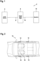
- Fig. 1 shows a sound system 2 in accordance with an exemplary embodiment of the invention in a block diagram.
- the sound system 2 is a car sound system.
- the sound system 2 may also be a sound system configured for a different application.
- the sound system 2 comprises an audio source 4, a digital audio filter 8 in accordance with an exemplary embodiment of the invention, and a plurality of active speakers 12.
- the audio source 4 is coupled to the digital audio filter 8.
- the output of the audio source 4 may result in a filter input 6 to the digital audio filter 8.
- the dashed line between the audio source 4 and the digital audio filter 8 in Fig. 1 indicates that additional signal processing may take place between the audio source 4 and the digital audio filter 8.
- one or more additional filters may be provided between the audio source 4 and the digital audio filter 8.
- the digital audio filter 8 transforms the filter input 6 into a filter output 10.
- the digital audio filter 8 is coupled to the speakers 12.
- the speakers 12 output audio content, resulting from the signal output 10 of the digital audio filter 8.
- the dashed line between the digital audio filter 8 and the speakers 12 indicates that additional signal processing may take place between the digital audio filter 8 and the speakers 12. In particular, one or more additional filters may be provided between the digital audio filter 8 and the speakers 12.
- a single signal line is depicted between the audio source 4 and the audio filter 8, and a single signal line is depicted between the digital audio filter 8 and the speakers 12.
- the audio signals may be one-channel audio signals or multi-channel audio signals, such as two-channel or three-channel or four-channel or five-channel or six-channel or seven-channel audio signals.
- the digital audio filter 8 may perform signal processing on individual channels or on subsets of channels or on all channels of the audio signal. The signal processing of the individual channels may be independent from each other. However, it is also possible that the signal processing in the digital audio filter 8 contains dependencies between the channels.
- the digital audio filter 8 is configured in accordance with an exemplary embodiment of the invention. This means that the digital audio filter 8 is configured in accordance with any of the methods for configuring a digital audio filter, as described above and/or as will be described below with respect to Figs. 3 to 7.
- Fig. 2 shows a car 14 that is equipped with a sound system in accordance with an exemplary embodiment of the invention in a cut-open top view.
- the sound system is the exemplary sound system 2 of Fig. 1 .
- the speakers 12 of the sound system are depicted in Fig. 2 .
- the other components of the sound system 2 in particular the audio source 4 and the digital audio filter 8, as shown in and described with respect to Fig. 1 , are also arranged in the car 14.
- they may be arranged in a dashboard portion of the car 14 and may be coupled to the speakers 12 via according audio lines.
- the sound system is also referred to as a car sound system.
- the speakers 12 are arranged in such a way that they output the audio content into a vehicle interior 16 of the car 14.
- the sound system of the car 14 is adapted to the particular auditory space of the vehicle interior 16.
- the sound system is adapted to the auditory space artefacts that are introduced by the particular layout of the vehicle interior 16.
- the auditory space artefacts may be caused by the relative positions of the speakers and the listener(s), the small size of the auditory space, the sound-reflecting windows, etc.
- the digital audio filter is adapted to the particular auditory space.
- the digital audio filter has at least one compensation component that is configured to compensate for auditory space artefacts of the vehicle interior 16. Such compensation may lead to a highly complex transfer function of the digital audio filter. As will be described below with respect to Figs.
- an initial set-up of the digital audio filter may be transformed into a modified set-up of the digital audio filter, with the transfer characteristics of the digital audio filter being closely controlled both in the time domain and the frequency domain during the manipulation.
- Such manipulation may take place in the design phase of the digital audio filter, when it is desired that a highly complex initial set-up of the digital audio filter may be reduced in signal processing complexity and/or may be selectively altered with respect to its transfer characteristics.
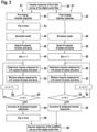
- Fig. 3 shows a flow diagram of a method for configuring a digital audio filter in accordance with an exemplary embodiment of the invention.
- the method starts at step 20 with the provision of an impulse response of an initial set-up of the digital audio filter.
- the initial set-up of the digital audio filter and the impulse response of said initial set-up may be readily available, when the method starts at step 20.
- the impulse response in the time domain is determined on the basis of a given initial set-up of the digital audio filter in another representation, e.g. on the basis of a given initial set-up of the digital audio filter in the frequency domain.
- the initial set-up of the digital audio filter and its impulse response are not yet available, but determined at the beginning of the method.
- the method aims at controlling the post-ringing of the digital audio filter and the pre-ringing of the digital audio filter.
- the post-ringing and the pre-ringing are addressed separately, with a first strand 21 of method steps addressing the post-ringing and a second strand 41 of method steps addressing the pre-ringing.
- the first strand 21 of method steps and the second strand 41 of method steps are depicted in parallel in Fig. 3 . It is pointed out that the parallel illustration of the first strand 21 of method steps and the second strand 41 of method steps is based on logical considerations. It is understood that the first strand 21 of method steps and the second strand 41 of methods steps may be carried out subsequently, when the method of Fig. 3 is carried out.
- the first strand 21 of method steps starts with the post-ringing impulse response of the digital audio filter.
- the post-ringing impulse response is a decaying impulse response in the time domain.
- the post-ringing impulse response represents a part of the transfer characteristics of the digital audio filter, namely the post-ringing characteristic of the audio filter.
- the post-ringing impulse response may be determined from the impulse response of step 20 or may be readily available, e.g. accessible from a memory.
- a zero/pole model of the post-ringing impulse response is provided.
- the poles and zeros of the post-ringing impulse response are determined in the z-domain.
- the zero/pole model has I zeros and m poles.
- the zero/pole model representing the post-ringing transfer characteristic of the digital audio filter, can have a large number of zeros and poles.
- the zero/pole model may have between 50 and 100 zeros and poles, respectively.
- N subsets of poles and zeros are selected.
- the exemplary method of Fig. 3 has the aim of controlling the post-ringing of the digital audio filter.
- the exemplary method of Fig. 3 has the aim of controlling the length of the post-ringing of the digital audio filter, without excessively manipulating the initial set-up of the digital audio filter.
- the exemplary method of Fig. 3 addresses low frequency portions of the digital audio filter, which tend to have a larger length in the post-ringing impulse response.
- fifteen predefined frequency intervals are defined between 20Hz and 375Hz and fifteen subsets of poles and zeros are selected in accordance with these predefined frequency intervals at step 26.
- the running variable n is used to subsequently address the N subsets of poles and zeros, as will be laid out below.
- the impulse response for the n-th subset of poles and zeros is determined.
- a so-called subset impulse response is determined in the time domain.
- the subset impulse response represents the post-ringing characteristic of the digital audio filter that is associated with the selected subset of poles and zeros, i.e. that is determined by those terms of the zero/pole model that relate to the selected pole(s) and/or zero(s).
- H z z ⁇ z i z ⁇ p j z ⁇ p j + 1 .
- the subset impulse response may be the time domain representation of the transfer function, associated with the particular subset.
- the subset impulse response is windowed.
- the subset impulse response associated with the n-th subset of poles and zeros, is windowed in the time domain.
- the windowing may include a clipping of the subset impulse response and/or a relative weighing of the values of the subset impulse response.
- a decreasing weighing of the values of the subset impulse response may be combined with a clipping of the subset impulse response after a certain period of time.
- Various window shapes may be used in step 32, such as a Gaussian window, an exponential window, a Hanning window, etc. The different window shapes will be illustrated in detail with respect to Fig. 4 .
- the window length is set in accordance with the frequency interval associated with the n-th subset of poles and zeros.
- a center frequency of the predefined frequency interval, associated with the n-th subset of poles and zeros is determined, and the window length is set to 10 times the period time of said center frequency.
- a frequency-selective control of the post-ringing of the digital audio filter may be achieved.
- a frequency-selective control of the post-ringing may be combined with maintaining particular frequency-dependent characteristics in the set-up of the digital audio filter.
- a high level of control of the transfer characteristics of the digital audio filter may be achieved both in the time domain and the frequency domain.
- n is incremented at step 36, and the first strand 21 of method steps returns to step 30. If n is equal to N, the subset impulse responses, associated with all N subsets of poles and zeros, have been addressed by windowing the respective subset impulse responses in the time domain, and the method proceeds to step 38.
- the N windowed impulse responses i.e. the N subset impulse responses, having experienced windowing in step 32, are convolved.
- a modified post-ringing impulse response of the digital audio filter is provided.
- Said modified post-ringing impulse response is the result of a controlled manipulation of the initial post-ringing pulse response, with said manipulation being highly targeted both in the time domain and the frequency domain.
- the exemplary method of Fig. 3 has a second strand 41 of method steps, which deal with the pre-ringing of the digital audio filter.
- the second strand 41 of method steps has various method steps that are analogous to the first strand 21 of method steps.
- the method steps of the second strand 41 of method steps are denoted with reference numerals that are incremented by 20.
- reference numerals that are incremented by 20.
- the second strand 41 of method steps starts with the provision of the pre-ringing impulse response of the initial set-up of the digital audio filter at step 42.
- the pre-ringing impulse response represents part of the transfer characteristics of the initial set-up of the digital audio filter, namely the pre-ringing transfer characteristic of the initial set-up of the digital audio filter.
- the pre-ringing impulse response is not a decaying impulse response. For this reason, the pre-ringing impulse response is flipped in time at step 43. The result of said flipping operation is a decaying impulse response.
- the flipped pre-ringing impulse response is processed in a manner analogous to the method steps 24, 26, 28, 30, 32, 34, 36, and 38, described above with respect to the post-ringing impulse response. While the individual method steps are conceptionally analogous, it is pointed out that a different number of subsets of poles and zeros may be selected, that the selection criteria for the subsets of poles and zeros may be different, and that the windowing of the subset impulse responses may be carried out with different window shapes and/or window lengths, as compared to the first strand 21 of method steps.
- the window lengths may be considerably shorter for step 52, in order to provide a stronger reduction and/or limitation of the pre-ringing of the digital audio filter.
- the window lengths, as used in step 52 may be between 1/4 and 1/2 of the window lengths, as used in step 32.
- method step 58 convolves the N windowed subset impulse responses, as created by N iterations of step 52.
- the resulting impulse response is flipped in time at method step 59.
- the result of method step 59 is a modified pre-ringing impulse response of the digital audio filter.
- step 60 the modified post-ringing impulse response and the modified pre-ringing impulse response are combined to form a modified total impulse response of the digital audio filter. It can also be said that step 60 yields the impulse response of the modified set-up of the digital audio filter.
- the exemplary method of Fig. 3 deals with both the post-ringing of the digital audio filter and the pre-ringing of the digital audio filter. It is pointed out that the method may also deal with the post-ringing only or with the pre-ringing only. It is further pointed out that the method in accordance with exemplary embodiments of the invention may also deal with other transfer characteristics of the digital audio filter. In other words, the splitting of the transfer characteristics of the digital audio filter into a post-ringing part and a pre-ringing part is exemplary only.
- the method as described herein may also split up the transfer characteristics of the digital audio filter in a different manner and may address differently sliced parts of the impulse response of the initial set-up of the digital audio filter.
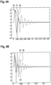
- Figs. 4A to 4D illustrate different window shapes for windowing subset impulse responses in the time domain.
- the illustrated windows may for example be used in method steps 32, 52, as illustrated in Fig. 3 and as described above.
- Fig. 4A depicts a subset impulse response 70 over time.
- the subset impulse response 70 is associated with a subset of poles and zeros around a center frequency of 62.5 Hz, with the predefined frequency interval, containing said subset of poles and zeros, being 25 Hz wide.
- a Gaussian window 71 is used for windowing the subset impulse response 70.
- the Gaussian window 71 is chosen to have a window length of 32 ms, which is twice the period time of the center frequency 62.5 Hz.
- the window length is defined as the duration within which the window 71 decays to -60 dB.
- the result of the windowing of the subset impulse response 70 with the Gaussian window 71 is the windowed subset impulse response 72.
- Fig. 4B illustrates another exemplary windowing of the subset impulse response 70.
- an exponential window 73 is applied to the subset impulse response 70.
- the exponential window 73 is chosen to have a window length of 32 ms, with the window length being defined as the duration within which the window decays to -60 dB.
- the result of the windowing of the subset impulse response 70 with the exponential window 73 is the windowed subset impulse response 74.
- Fig. 4C illustrates another exemplary windowing of the subset impulse response 70.
- a rectangular window 75 of a window length of 32 ms is applied to the subset impulse response 70.
- the result of the windowing of the subset impulse response 70 with the rectangular window 75 is the windowed subset impulse response 76.
- Fig. 4D illustrates another exemplary windowing of the subset impulse response 70.
- a Hanning window is applied to the subset impulse response 70.
- the Hanning window 77 has a window length of 32 ms, with the window length being defined as the decay from one to zero on a dimensionless scale.
- the result of the windowing of the subset impulse response 70 with the Hanning window 77 is the windowed subset impulse response 78.
- Fig. 5 illustrates the windowing of a subset impulse response with different window lengths.
- the illustrated windows may for example be used in method steps 32, 52, as illustrated in Fig. 3 and as described above.
- Fig. 5 depicts the subset impulse response 70, as already depicted in Figs. 4A to 4D .
- Fig. 5 illustrates the application of three different Hanning windows, namely a first Hanning window 79, having a window length of 2 periods of the center frequency of the predefined frequency interval, a second Hanning window 81, having a window length of 6 periods of the center frequency, and a third Hanning window 83, having a window length of 10 periods of the center frequency.
- the application of the first Hanning window 79 to the subset impulse response 70 results in the first windowed subset impulse response 80.
- the application of the second Hanning window 81 to the subset impulse response 70 results in the second windowed subset impulse response 82.
- the application of the third Hanning window 83 to the subset impulse response 70 results in the third windowed subset impulse response 84.
- Fig. 6 illustrates a potential effect of the method for configuring a digital audio filter in accordance with an exemplary embodiment of the invention via illustrating the effect on a portion of the transfer characteristics of an exemplary digital audio filter.
- Fig. 6A shows a portion of the transfer characteristics of an exemplary digital audio filter in the frequency domain.
- Fig. 6A illustrates a portion of the frequency response of the exemplary digital audio filter, with the depicted portion ranging from 20 Hz to 250 Hz.
- Fig. 6A depicts an initial frequency response 97, i.e. a frequency response in accordance with an initial set-up of the digital audio filter, and a modified frequency response 98, i.e. a frequency response in accordance with the modified set-up of the digital audio filter.
- the modified frequency response 98 is the result of the windowing of various subset impulse responses, each associated with a respective subset of the poles and zeros of a decaying impulse response that represents a part of the transfer characteristics of the initial set-up of the digital audio filter.
- Fig. 6A In the embedded diagram of Fig. 6A , three initial subset frequency responses 91, 93, 95 and three associated modified frequency impulse response 92, 94, 96 are depicted.
- the given frequency responses are transfer functions corresponding to respective subsets of the poles and zeros of the decaying impulse response of the initial set-up of the digital audio filter. While being shown in the frequency domain, it is understood that the modification via windowing has taken place in the time domain, as for example described with respect to Fig. 3 .
- the modified frequency responses 92, 94, 96 are the results of different window lengths for the windowing operation.
- the comparably longer window allows for the third modified frequency response 96 to conform closer to the third initial frequency response 95. In this way, the dip in the total frequency response 98 at about 140 Hz may be maintained, while other portions of the initial frequency response 97 are smoothened to a greater degree.
- a frequency-selective manipulation of the transfer characteristics of the digital audio filter may achieved, maintaining selected characteristic, while smoothing other characteristics. Exemplary embodiments of the invention allow for an effective way of reducing the complexity of the transfer characteristics of the digital audio filter, while maintaining desired features in a targeted manner. A highly targeted control of the transfer characteristics of the digital audio filter may be achieved.
- Fig. 6B shows a comparative example where the subset impulse responses are windowed with the same / corresponding window lengths.
- the frequency dip at about 140 Hz is not maintained, when comparably short window lengths are used for all subset impulse responses.
Landscapes
- Engineering & Computer Science (AREA)
- Multimedia (AREA)
- Physics & Mathematics (AREA)
- Acoustics & Sound (AREA)
- Signal Processing (AREA)
- Stereophonic System (AREA)
- Circuit For Audible Band Transducer (AREA)
Description
- The present invention is in the field of digital filtering of audio signals. In particular, the present invention is in the field of configuring a digital audio filter for a pleasing sound experience.
- Modern digital audio filters have become more and more complex. One reason for the increasing complexity is the aim to compensate for the room acoustics in a listening position. Attempts to adapt an audio output to a particular auditory space by compensating for auditory space artifacts may lead to complex digital audio filters. The complex signal processing may make it difficult to have good control over the filter characteristics. In particular, it may be difficult to manipulate the filter characteristics in a highly targeted manner. Further in particular, manipulations in the time domain or in the frequency domain may have undesirably broad effects in the respectively other domain. This in turn may lead to undesired degradations of the sound experience for a listener.
- Goodwin M M, "Realization of arbitrary filter in the STFT domain", 2009 IEEE Workshop on Application of Signal Processing to Audio and Acoustics discloses how to realize arbitrary FIR and IIR filters in an STFT framework whose block size, hop size, and transform size are not constrained by the target filter response.
- It would be beneficial to provide a method for configuring a digital audio filter that allows for a highly targeted control of the filter characteristics, even in the context of complex filter designs / set-ups. It would also be beneficial to provide a digital audio filter having such configuration.
- Exemplary embodiments of the invention include a method for configuring a digital audio filter in accordance with
claim 1 and a vehicle sound system in accordance with claim 11. Further embodiments of the invention are given in the dependent claims. - Exemplary embodiments of the invention include a method for configuring a digital audio filter, comprising: providing a decaying impulse response in the time domain, representing at least part of the transfer characteristics of the digital audio filter; determining the poles and zeros of the decaying impulse response in the z-domain; selecting at least one subset of the poles and zeros of the decaying impulse response; and, for each of the at least one subset of the poles and zeros: determining a respective subset impulse response in the time domain, windowing the respective subset impulse response in the time domain, and configuring the digital audio filter in accordance with the windowed respective subset impulse response.
- Exemplary embodiments of the invention allow for manipulating the transfer characteristics of a digital audio filter in a manner that is highly targeted both in the time domain and the frequency domain. By addressing a particular subset of the poles and zeros of the decaying impulse response and by manipulating a subset impulse response, i.e. an impulse response associated with the subset of the poles and zeros selected, the manipulation may be highly targeted in the frequency domain. By windowing the subset impulse response in the time domain, a highly targeted manipulation in the time domain may be achieved. As compared to previous approaches, where a highly targeted manipulation in one of the time and frequency domains was associated with an undesirably broad effect in the other one of the time and frequency domains, the method in accordance with exemplary embodiments of the invention may allow for a particularly good trade-off in controlling the transfer characteristics of the digital audio filter in the time domain and the frequency domain.
- The method comprises the step of providing a decaying impulse response in the time domain, representing at least part of the transfer characteristics of the digital audio filter. The expression providing a decaying impulse response in the time domain may refer to determining a desired decaying impulse response in the time domain on the basis of desired impulse response characteristics. It may also refer to determining the decaying impulse response from another representation of the transfer characteristics of the digital audio filter, such as from a transfer function in the frequency domain. The expression may also refer to accessing a decaying impulse response in the time domain that is readily accessable, such as from a previously determined initial configuration / set-up of the digital audio filter. The expression of representing at least part of the transfer characteristics of the digital audio filter means that the decaying impulse response represents part of the transfer characteristics of an initial set-up of the digital audio filter, i.e. a set-up of the digital audio filter before the ensuing method steps are carried out. The decaying impulse response may represent part of the transfer characteristics of the digital audio filter or all of the transfer characteristics of the digital audio filter.
- As stated above, exemplary embodiments of the invention relate to a method for configuring a digital audio filter. The method for configuring a digital audio filter may also be referred to as a method for adapting an initial set-up of the digital audio filter and forming a modified set-up of the digital audio filter. The decaying impulse response may represent at least part of the initial set-up of the digital audio filter, with the ensuing method steps manipulating set decaying impulse response and, thus, resulting in a modified set-up of the digital audio filter. The modified set-up of the digital audio filter may be a final set-up of the digital audio filter or may be subject to further modifications.
- The method comprises selecting at least one subset of the poles and zeros of the decaying impulse response. The term subset may refer to any subset of the total set of poles and zeros. In particular, the subset may comprise one, two, three, four, five, six, seven, eight, nine, ten or more poles/zeros. Further in particular, the subset may comprise only poles or only zeros or a combination of poles and zeros. The one or more subsets may be selected in accordance with various criteria, as will be laid out in more detail below.
- The method comprises determining a respective subset impulse response in the time domain for a given subset of the poles and zeros. The term subset impulse response refers to an impulse response of a transfer function that is determined by the given subset of the poles and zeros. In other words, the given subset of the poles and zeros determine transfer characteristics in the frequency domain, with the subset impulse response representing said transfer characteristics in the time domain.
- The method comprises windowing the subset impulse response in the time domain. The windowing is a manipulation of the subset impulse response in the time domain. The windowing may be performed with a variety of different windows, as will be laid out below. The windowing may include a weighing of individual values in the subset impulse response, depending on their position along the time axis, and/or a clipping of the subset impulse response in the time domain. The windowing of the respective subset impulse response in the time domain yields a windowed respective subset impulse response. While the term respective subset impulse response refers to a component of the transfer characteristics of the initial set-up of the digital audio filter, the term windowed respective subset impulse response refers to a component of the modified set-up of the digital audio filter.
- The method includes configuring the digital audio filter in accordance with the windowed subset impulse response. Said configuring of the digital audio filter may also be viewed as using the windowed subset impulse response in the digital audio filter, instead of the un-windowed subset impulse response, i.e. instead of the subset impulse response that is the result of the step of determining a subset impulse response in the time domain. Stated differently, the step of configuring the digital audio filter in accordance with the windowed respective subset impulse response may be viewed as replacing that part of the decaying impulse response that is associated with the subset of the poles and zeros in question with the windowed respective subset impulse response. In this way, the decaying impulse response may be manipulated in a highly targeted manner, depending on the particular selection of the subset of the poles and zeros.
- The step of selecting at least one subset of the poles and zeros of the decaying impulse response comprises: grouping poles and zeros of the decaying impulse response in accordance with at least one predefined frequency interval. The selecting of the at least one subset of the poles and zeros may comprise checking if and how many poles and zeros are within one or more predefined frequency intervals and combining those poles and zeros within the one or more predefined frequency intervals, if present, into said at least one subset of the poles and zeros. The step of selecting at least one subset of the poles and zeros may provide an effective means for targeting certain frequency intervals for manipulation, while maintaining a manageable level of complexity by grouping the poles and zeros in accordance with the one or more predefined frequency intervals. The predefined frequency intervals may span the whole audible range from about 20 Hz to about 20 kHz or may span one or more portions thereof.
- According to a further embodiment, said grouping of poles and zeros in accordance with at least one predefined frequency interval comprises grouping poles and zeros in accordance with between 5 and 30 predefined frequency intervals. In particular, it may comprise grouping poles and zeros in accordance with between 10 and 20 predefined frequency intervals. Further in particular, it may comprise grouping poles and zeros in accordance with 15 predefined frequency intervals. It has been found that said numbers of frequency intervals provide for a good trade-off between a highly targeted manipulation in the frequency domain, while maintaining a manageable level of complexity. In a particular example, 15 predefined frequency intervals may be provided for a frequency range from 20 Hz to 375 Hz. In this way, a highly targeted manipulation of the transfer characteristics of the digital audio filter at very low frequencies in the audible spectrum may be achieved.
- According to a further embodiment, the step of selecting at least one subset of the poles and zeros of the decaying impulse response comprises: grouping poles and zeros of the decaying impulse response in accordance with at least one predefined quality factor interval, also referred to as Q factor interval. In a particular embodiment, said grouping of poles and zeros may be carried out in accordance with a plurality of quality factor intervals. In this way, similarly damped portions of the decaying impulse response may be handled in a joint manner, providing a targeted manipulation of the decaying impulse response, while maintaining a manageable level of complexity. The grouping in accordance with one or more predefined quality factor intervals may be carried out in addition / as an alternative to above discussed grouping in accordance with one or more predefined frequency intervals.
- According to a further embodiment, the method comprises: selecting a plurality of subsets of the poles and zeros of the decaying impulse response; and, for each of the plurality of subsets of the poles and zeros: determining the respective subset impulse response in the time domain, windowing the respective subset impulse response in the time domain, and configuring the digital audio filter in accordance with the windowed respective subset impulse response.
- According to a further embodiment, for at least two of the plurality of subsets of the poles and zeros, the windowing of the respective subset impulse responses in the time domain is carried out with different window lengths and/or different window shapes. In this way, the different subset impulse responses, associated with different subsets of the poles and zeros, may be addressed and manipulated in an individualized manner. A highly targeted decay time control may be exerted, in particular in a frequency-selective manner. In terms of the window shapes, it is possible to use Gaussian windows and/or exponential windows and/or Hanning windows and/or rectangular windows and/or other window shapes, in particular specifically designed window shapes. In terms of window lengths, the windows may have different lengths in absolute terms. i.e. different lengths on a time scale, or may have different lengths in relation to the period lengths of the targeted frequency range. For example, for a given predefined frequency interval, it is possible to determine the center frequency and to set the window length to a certain number of period times at that center frequency. For example, the window lengths may be between 2 period times and 20 period times of the center frequency. Via the different window shapes and/or the different window lengths, the decay characteristics and/or the decay time of the subset impulse response in question may be manipulated / controlled in a targeted manner. The window lengths and/or the window shapes may be different for all of the plurality of subsets of the poles and zeros or for some of the plurality of subsets of the poles and zeros. In other words, it is possible that some of the plurality of subsets of the poles and zeros are windowed with the same window lengths and/or window shapes, while other subset impulse responses are windowed differently.
- According to a further embodiment, the method further comprises: convolving the windowed respective subset impulse responses for configuring the digital audio filter. Convolving the windowed respective subset impulse responses is an effective means for providing the digital audio filter in such a way that the modifications, introduced by the windowing of the respective subset impulse responses, are all reflected in the modified set-up of the digital audio filter.
- According to a further embodiment, the decaying impulse response represents a post-ringing transfer characteristic of the digital audio filter. In this way, the post-ringing of the digital audio filter may be controlled in a highly targeted manner.
- According to a further embodiment, the decaying impulse response represents a pre-ringing transfer characteristic of the digital audio filter, flipped in time. In this way, the pre-ringing of the digital audio filter may be controlled in a highly targeted manner.
- According to a further embodiment, the method comprises: providing a plurality of decaying impulse responses, with each of the plurality of decaying impulse responses representing a respective part of the transfer characteristics of the digital audio filter, wherein method steps in accordance with any of the embodiments, as described above, are carried out on each of the plurality of decaying impulse responses. In this way, different parts of the transfer characteristics of the digital audio filter may be addressed / manipulated / controlled in a particularly targeted manner.
- According to a further embodiment, the plurality of decaying impulse responses comprises a first decaying impulse response, representing a post-ringing transfer characteristic of the digital audio filter, and a second decaying impulse response, representing a pre-ringing transfer characteristic of the digital audio filter, flipped in time.
- According to a further embodiment, the method further comprises: providing a finite impulse response (FIR) filter implementation in the time domain or a block-based filter implementation in the frequency domain for the digital audio filter. The providing of the FIR filter implementation may in particular comprise setting the length and the parameters of the FIR filter. In this way, a ready to use configuration for the digital audio filter may be provided. It is pointed out that other types of implementations of the digital audio filter are possible as well. In particular, any kind of filter architecture that is suitable for providing an implementation of the modified set-up of the digital audio filter or an implementation of an approximation of the modified set-up of the digital audio filter may be employed.
- According to a further embodiment, the digital audio filter comprises a compensation component for auditory space artefacts. In a particular embodiment, the digital audio filter comprises a compensation component, representing a compensation for auditory space artefacts of a vehicle interior. A vehicle interior has a complex geometry for a sound system, inter alia due to the fixed positions for the speakers, the fixed listening position(s), the small size of the auditory space, the sound-reflecting windows, etc. In order to counteract these artefacts, complex compensation components may be employed in digital audio filters. The tight control of the transfer characteristics of a digital audio filter, as described herein, is particularly beneficial when dealing with the compensation of auditory space artefacts.
- Also disclosed herein is a digital audio filter, configured in accordance with the method for configuring a digital audio filter, as described in any of the embodiments above. The additional features, modifications and effects, as discussed above with respect to a method for configuring a digital audio filter, apply to the digital audio filter in an analogous manner. In particular, the digital audio filter may provide for a particularly pleasing listening experience, as desired / undesired elements of the transfer characteristics may be effectively controlled in the design phase. The digital audio filter may apply the configured transfer characteristics to an audio signal, before the audio signal is .output to the auditory space.
- Exemplary embodiments of the invention further include a sound system, comprising a digital audio filter as described above. The additional features, modifications and effects, as described above with respect to the method for configuring a digital audio filter and with respect to the digital audio filter, apply to the sound system in an analogous manner. The sound system may comprise further components. In particular, the sound system may comprise an audio source and one or more speakers. In a particular embodiment, the sound system may comprise two, three, four, five, six, seven or more speakers. Besides the digital audio filter, the audio source, and the speaker(s), the sound system may comprise further audio filters. The audio source may be coupled to the digital audio filter described herein, either directly or indirectly, and the digital audio filter described herein may be coupled to the speaker(s), either directly or indirectly.
- The sound system is a vehicle sound system. In particular, the sound system may be a car sound system. The effects, as described herein, may be particularly useful in the car environment, because a car interior is a very complex auditory space and there is a lot of room for enhancing the listening experience for the driver and/or the passenger(s) in the car.
- Exemplary embodiments of the invention further include a method for outputting audio content into a vehicle interior, the method comprising: filtering a digital audio signal with a digital audio filter, as described in any of the embodiments above; and outputting audio content, based on the filtered digital audio signal, via speakers arranged in the vehicle interior. The additional features, modifications, and effects, as described above with respect to the method for configuring a digital audio filter, the digital audio filter, and the sound system, apply to the method for outputting audio content into the vehicle interior in an analogous manner.
- Further exemplary embodiments of the invention are described with respect to the accompanying drawings, wherein:
-
Fig. 1 shows a sound system in accordance with an exemplary embodiment of the invention in a block diagram; -
Fig. 2 shows a car in a cut-open top view, the car being equipped with the sound system ofFig. 1 ; -
Fig. 3 shows a flow diagram for a method for configuring a digital audio filter in accordance with an exemplary embodiment of the invention; -
Fig. 4 illustrates different window shapes, as may be used in methods for configuring digital audio filters in accordance with an exemplary embodiments of the invention; -
Fig. 5 illustrates different window lengths, as may be used in methods for configuring digital audio filters in accordance with an exemplary embodiments of the invention; -
Fig. 6 illustrates an effect of the method for configuring a digital audio filter in accordance with an exemplary embodiment of the invention on the transfer characteristics of an exemplary digital audio filter. -
Fig. 1 shows asound system 2 in accordance with an exemplary embodiment of the invention in a block diagram. In the exemplary embodiment ofFig. 1 , thesound system 2 is a car sound system. However, it is pointed out that thesound system 2 may also be a sound system configured for a different application. - The
sound system 2 comprises anaudio source 4, adigital audio filter 8 in accordance with an exemplary embodiment of the invention, and a plurality ofactive speakers 12. Theaudio source 4 is coupled to thedigital audio filter 8. In particular, the output of theaudio source 4 may result in afilter input 6 to thedigital audio filter 8. The dashed line between theaudio source 4 and thedigital audio filter 8 inFig. 1 indicates that additional signal processing may take place between theaudio source 4 and thedigital audio filter 8. In particular, one or more additional filters may be provided between theaudio source 4 and thedigital audio filter 8. - The
digital audio filter 8 transforms thefilter input 6 into afilter output 10. Thedigital audio filter 8 is coupled to thespeakers 12. In operation, thespeakers 12 output audio content, resulting from thesignal output 10 of thedigital audio filter 8. The dashed line between thedigital audio filter 8 and thespeakers 12 indicates that additional signal processing may take place between thedigital audio filter 8 and thespeakers 12. In particular, one or more additional filters may be provided between thedigital audio filter 8 and thespeakers 12. - In the illustration of
Fig. 1 , a single signal line is depicted between theaudio source 4 and theaudio filter 8, and a single signal line is depicted between thedigital audio filter 8 and thespeakers 12. It is understood that the audio signals may be one-channel audio signals or multi-channel audio signals, such as two-channel or three-channel or four-channel or five-channel or six-channel or seven-channel audio signals. Thedigital audio filter 8 may perform signal processing on individual channels or on subsets of channels or on all channels of the audio signal. The signal processing of the individual channels may be independent from each other. However, it is also possible that the signal processing in thedigital audio filter 8 contains dependencies between the channels. - The
digital audio filter 8 is configured in accordance with an exemplary embodiment of the invention. This means that thedigital audio filter 8 is configured in accordance with any of the methods for configuring a digital audio filter, as described above and/or as will be described below with respect toFigs. 3 to 7. -
Fig. 2 shows acar 14 that is equipped with a sound system in accordance with an exemplary embodiment of the invention in a cut-open top view. In the exemplary embodiment ofFig. 2 , the sound system is theexemplary sound system 2 ofFig. 1 . For ease of illustration, only thespeakers 12 of the sound system are depicted inFig. 2 . It is understood that the other components of thesound system 2, in particular theaudio source 4 and thedigital audio filter 8, as shown in and described with respect toFig. 1 , are also arranged in thecar 14. For example, they may be arranged in a dashboard portion of thecar 14 and may be coupled to thespeakers 12 via according audio lines. Being part of and being configured for thecar 14, the sound system is also referred to as a car sound system. - The
speakers 12 are arranged in such a way that they output the audio content into avehicle interior 16 of thecar 14. In the exemplary embodiment ofFig. 2 , there are fourspeakers 12, which are arranged in the left front door, the right front door, the left rear door, and the right rear door. It is understood that other numbers of speakers and other arrangements in thevehicle interior 16 are possible as well. - The sound system of the
car 14 is adapted to the particular auditory space of thevehicle interior 16. In other words, the sound system is adapted to the auditory space artefacts that are introduced by the particular layout of thevehicle interior 16. The auditory space artefacts may be caused by the relative positions of the speakers and the listener(s), the small size of the auditory space, the sound-reflecting windows, etc. The digital audio filter is adapted to the particular auditory space. In particular, the digital audio filter has at least one compensation component that is configured to compensate for auditory space artefacts of thevehicle interior 16. Such compensation may lead to a highly complex transfer function of the digital audio filter. As will be described below with respect toFigs. 3 to 7, an initial set-up of the digital audio filter may be transformed into a modified set-up of the digital audio filter, with the transfer characteristics of the digital audio filter being closely controlled both in the time domain and the frequency domain during the manipulation. Such manipulation may take place in the design phase of the digital audio filter, when it is desired that a highly complex initial set-up of the digital audio filter may be reduced in signal processing complexity and/or may be selectively altered with respect to its transfer characteristics. -
Fig. 3 shows a flow diagram of a method for configuring a digital audio filter in accordance with an exemplary embodiment of the invention. The method starts atstep 20 with the provision of an impulse response of an initial set-up of the digital audio filter. The initial set-up of the digital audio filter and the impulse response of said initial set-up may be readily available, when the method starts atstep 20. It is also possible that the impulse response in the time domain is determined on the basis of a given initial set-up of the digital audio filter in another representation, e.g. on the basis of a given initial set-up of the digital audio filter in the frequency domain. It is further possible that the initial set-up of the digital audio filter and its impulse response are not yet available, but determined at the beginning of the method. - In the exemplary embodiment of
Fig. 3 , the method aims at controlling the post-ringing of the digital audio filter and the pre-ringing of the digital audio filter. The post-ringing and the pre-ringing are addressed separately, with afirst strand 21 of method steps addressing the post-ringing and asecond strand 41 of method steps addressing the pre-ringing. Thefirst strand 21 of method steps and thesecond strand 41 of method steps are depicted in parallel inFig. 3 . It is pointed out that the parallel illustration of thefirst strand 21 of method steps and thesecond strand 41 of method steps is based on logical considerations. It is understood that thefirst strand 21 of method steps and thesecond strand 41 of methods steps may be carried out subsequently, when the method ofFig. 3 is carried out. - At
step 22, thefirst strand 21 of method steps starts with the post-ringing impulse response of the digital audio filter. The post-ringing impulse response is a decaying impulse response in the time domain. The post-ringing impulse response represents a part of the transfer characteristics of the digital audio filter, namely the post-ringing characteristic of the audio filter. The post-ringing impulse response may be determined from the impulse response ofstep 20 or may be readily available, e.g. accessible from a memory. - At
step 24, a zero/pole model of the post-ringing impulse response is provided. The poles and zeros of the post-ringing impulse response are determined in the z-domain. The zero/pole model may be expressed as:
- According to the general writing of the foregoing formula, the zero/pole model has I zeros and m poles. In complex digital audio filters, the zero/pole model, representing the post-ringing transfer characteristic of the digital audio filter, can have a large number of zeros and poles. For example, the zero/pole model may have between 50 and 100 zeros and poles, respectively.
- At
step 26, N subsets of poles and zeros are selected. As stated above, the exemplary method ofFig. 3 has the aim of controlling the post-ringing of the digital audio filter. In particular, the exemplary method ofFig. 3 has the aim of controlling the length of the post-ringing of the digital audio filter, without excessively manipulating the initial set-up of the digital audio filter. On the basis of these considerations, the exemplary method ofFig. 3 addresses low frequency portions of the digital audio filter, which tend to have a larger length in the post-ringing impulse response. In the exemplary embodiment ofFig. 3 , fifteen predefined frequency intervals are defined between 20Hz and 375Hz and fifteen subsets of poles and zeros are selected in accordance with these predefined frequency intervals atstep 26. The selection of fifteen subsets of poles and zeros is based on the assumption that there are zero(s) and/or pole(s) in each of the fifteen predefined frequency intervals. It is understood that it is also possible that step 26 checks fifteen predefined frequency intervals for poles and zeros and that a smaller number of predefined frequency intervals actually has pole(s) and/or zero(s). In this case, N is also smaller than fifteen. It is further understood that N=15 ist purely exemplary and that any other number of subset of poles and zeros may be selected. - At
step 28, a running variable n is initialized and set to 1, i.e. n=1. The running variable n is used to subsequently address the N subsets of poles and zeros, as will be laid out below. - At
step 30, the impulse response for the n-th subset of poles and zeros is determined. In particular, for those pole(s) and/or zero(s) of the zero/pole model that are part of the n-th subset of poles and zeros, a so-called subset impulse response is determined in the time domain. The subset impulse response represents the post-ringing characteristic of the digital audio filter that is associated with the selected subset of poles and zeros, i.e. that is determined by those terms of the zero/pole model that relate to the selected pole(s) and/or zero(s). For example, in the z-domain, the transfer function of a particular subset, consisting of two poles and one zero, may be written as:
- The subset impulse response may be the time domain representation of the transfer function, associated with the particular subset.
- At
step 32, the subset impulse response, as determined instep 30, is windowed. In particular, the subset impulse response, associated with the n-th subset of poles and zeros, is windowed in the time domain. The windowing may include a clipping of the subset impulse response and/or a relative weighing of the values of the subset impulse response. In particular, a decreasing weighing of the values of the subset impulse response may be combined with a clipping of the subset impulse response after a certain period of time. Various window shapes may be used instep 32, such as a Gaussian window, an exponential window, a Hanning window, etc. The different window shapes will be illustrated in detail with respect toFig. 4 . - In the exemplary embodiment of
Fig. 3 , the window length, as used instep 32, is set in accordance with the frequency interval associated with the n-th subset of poles and zeros. In a particular example, a center frequency of the predefined frequency interval, associated with the n-th subset of poles and zeros, is determined, and the window length is set to 10 times the period time of said center frequency. In this way, the characteristics of the post-ringing at the particular frequency interval are maintained to some extent, while the length of the subset impulse response is limited and, thus, the length of the overall post-ringing may be controlled. Also, with the window length being dependent on the predefined frequency interval, associated with the n-th subset of poles and zeros, a frequency-selective control of the post-ringing of the digital audio filter may be achieved. A frequency-selective control of the post-ringing may be combined with maintaining particular frequency-dependent characteristics in the set-up of the digital audio filter. A high level of control of the transfer characteristics of the digital audio filter may be achieved both in the time domain and the frequency domain. - At
step 34, it is checked whether n is equal to N. If not, n is incremented atstep 36, and thefirst strand 21 of method steps returns to step 30. If n is equal to N, the subset impulse responses, associated with all N subsets of poles and zeros, have been addressed by windowing the respective subset impulse responses in the time domain, and the method proceeds to step 38. - At
step 38, the N windowed impulse responses, i.e. the N subset impulse responses, having experienced windowing instep 32, are convolved. As a result of said convolving of the N windowed impulse responses, a modified post-ringing impulse response of the digital audio filter is provided. Said modified post-ringing impulse response is the result of a controlled manipulation of the initial post-ringing pulse response, with said manipulation being highly targeted both in the time domain and the frequency domain. - As stated before, the exemplary method of
Fig. 3 has asecond strand 41 of method steps, which deal with the pre-ringing of the digital audio filter. Thesecond strand 41 of method steps has various method steps that are analogous to thefirst strand 21 of method steps. As compared to those method steps, the method steps of thesecond strand 41 of method steps are denoted with reference numerals that are incremented by 20. For a detailed description of those method steps, reference is made to above description of thefirst strand 21 of method steps. The description applies to thesecond strand 41 of method steps in an analogous manner, unless indicated otherwise. - The
second strand 41 of method steps starts with the provision of the pre-ringing impulse response of the initial set-up of the digital audio filter atstep 42. The pre-ringing impulse response represents part of the transfer characteristics of the initial set-up of the digital audio filter, namely the pre-ringing transfer characteristic of the initial set-up of the digital audio filter. The pre-ringing impulse response is not a decaying impulse response. For this reason, the pre-ringing impulse response is flipped in time at step 43. The result of said flipping operation is a decaying impulse response. - In steps 44, 46, 48, 50, 52, 54, 56, and 58, the flipped pre-ringing impulse response is processed in a manner analogous to the method steps 24, 26, 28, 30, 32, 34, 36, and 38, described above with respect to the post-ringing impulse response. While the individual method steps are conceptionally analogous, it is pointed out that a different number of subsets of poles and zeros may be selected, that the selection criteria for the subsets of poles and zeros may be different, and that the windowing of the subset impulse responses may be carried out with different window shapes and/or window lengths, as compared to the
first strand 21 of method steps. In particular, the window lengths may be considerably shorter forstep 52, in order to provide a stronger reduction and/or limitation of the pre-ringing of the digital audio filter. For example, the window lengths, as used instep 52, may be between 1/4 and 1/2 of the window lengths, as used instep 32. - Analogous to
method step 38,method step 58 convolves the N windowed subset impulse responses, as created by N iterations ofstep 52. - The resulting impulse response is flipped in time at
method step 59. The result ofmethod step 59 is a modified pre-ringing impulse response of the digital audio filter. - At
step 60, the modified post-ringing impulse response and the modified pre-ringing impulse response are combined to form a modified total impulse response of the digital audio filter. It can also be said thatstep 60 yields the impulse response of the modified set-up of the digital audio filter. - The exemplary method of
Fig. 3 deals with both the post-ringing of the digital audio filter and the pre-ringing of the digital audio filter. It is pointed out that the method may also deal with the post-ringing only or with the pre-ringing only. It is further pointed out that the method in accordance with exemplary embodiments of the invention may also deal with other transfer characteristics of the digital audio filter. In other words, the splitting of the transfer characteristics of the digital audio filter into a post-ringing part and a pre-ringing part is exemplary only. While said splitting up of the impulse response of the initial set-up of the digital audio filter into a post-ringing part and a pre-ringing part provides for an effective way of controlling the transfer characteristics of the digital audio filter, the method as described herein may also split up the transfer characteristics of the digital audio filter in a different manner and may address differently sliced parts of the impulse response of the initial set-up of the digital audio filter. -
Figs. 4A to 4D illustrate different window shapes for windowing subset impulse responses in the time domain. The illustrated windows may for example be used in method steps 32, 52, as illustrated inFig. 3 and as described above. -
Fig. 4A depicts asubset impulse response 70 over time. In the depicted exemplary illustration, thesubset impulse response 70 is associated with a subset of poles and zeros around a center frequency of 62.5 Hz, with the predefined frequency interval, containing said subset of poles and zeros, being 25 Hz wide. - In the exemplary illustration of
Fig. 4A , aGaussian window 71 is used for windowing thesubset impulse response 70. TheGaussian window 71 is chosen to have a window length of 32 ms, which is twice the period time of the center frequency 62.5 Hz. In the exemplary illustration, the window length is defined as the duration within which thewindow 71 decays to -60 dB. The result of the windowing of thesubset impulse response 70 with theGaussian window 71 is the windowedsubset impulse response 72. -
Fig. 4B illustrates another exemplary windowing of thesubset impulse response 70. In particular, anexponential window 73 is applied to thesubset impulse response 70. Theexponential window 73 is chosen to have a window length of 32 ms, with the window length being defined as the duration within which the window decays to -60 dB. The result of the windowing of thesubset impulse response 70 with theexponential window 73 is the windowedsubset impulse response 74. -
Fig. 4C illustrates another exemplary windowing of thesubset impulse response 70. In particular, arectangular window 75 of a window length of 32 ms is applied to thesubset impulse response 70. The result of the windowing of thesubset impulse response 70 with therectangular window 75 is the windowedsubset impulse response 76. -
Fig. 4D illustrates another exemplary windowing of thesubset impulse response 70. In particular, a Hanning window is applied to thesubset impulse response 70. TheHanning window 77 has a window length of 32 ms, with the window length being defined as the decay from one to zero on a dimensionless scale. The result of the windowing of thesubset impulse response 70 with theHanning window 77 is the windowedsubset impulse response 78. -
Fig. 5 illustrates the windowing of a subset impulse response with different window lengths. The illustrated windows may for example be used in method steps 32, 52, as illustrated inFig. 3 and as described above. -
Fig. 5 depicts thesubset impulse response 70, as already depicted inFigs. 4A to 4D .Fig. 5 illustrates the application of three different Hanning windows, namely afirst Hanning window 79, having a window length of 2 periods of the center frequency of the predefined frequency interval, asecond Hanning window 81, having a window length of 6 periods of the center frequency, and athird Hanning window 83, having a window length of 10 periods of the center frequency. The application of thefirst Hanning window 79 to thesubset impulse response 70 results in the first windowedsubset impulse response 80. The application of thesecond Hanning window 81 to thesubset impulse response 70 results in the second windowedsubset impulse response 82. The application of thethird Hanning window 83 to thesubset impulse response 70 results in the third windowedsubset impulse response 84. -
Fig. 6 illustrates a potential effect of the method for configuring a digital audio filter in accordance with an exemplary embodiment of the invention via illustrating the effect on a portion of the transfer characteristics of an exemplary digital audio filter. -
Fig. 6A shows a portion of the transfer characteristics of an exemplary digital audio filter in the frequency domain. In particular,Fig. 6A illustrates a portion of the frequency response of the exemplary digital audio filter, with the depicted portion ranging from 20 Hz to 250 Hz. In the depicted frequency range,Fig. 6A depicts aninitial frequency response 97, i.e. a frequency response in accordance with an initial set-up of the digital audio filter, and a modifiedfrequency response 98, i.e. a frequency response in accordance with the modified set-up of the digital audio filter. The modifiedfrequency response 98 is the result of the windowing of various subset impulse responses, each associated with a respective subset of the poles and zeros of a decaying impulse response that represents a part of the transfer characteristics of the initial set-up of the digital audio filter. - In the embedded diagram of
Fig. 6A , three initialsubset frequency responses frequency impulse response Fig. 3 . In the exemplary embodiment ofFig. 6A , the modifiedfrequency responses subset frequency response 91 and the secondsubset frequency response 93, a comparably longer window has been used for windowing the subset impulse response, associated with the thirdsubset frequency response 95. The comparably longer window allows for the third modifiedfrequency response 96 to conform closer to the thirdinitial frequency response 95. In this way, the dip in thetotal frequency response 98 at about 140 Hz may be maintained, while other portions of theinitial frequency response 97 are smoothened to a greater degree. A frequency-selective manipulation of the transfer characteristics of the digital audio filter may achieved, maintaining selected characteristic, while smoothing other characteristics. Exemplary embodiments of the invention allow for an effective way of reducing the complexity of the transfer characteristics of the digital audio filter, while maintaining desired features in a targeted manner. A highly targeted control of the transfer characteristics of the digital audio filter may be achieved. -
Fig. 6B shows a comparative example where the subset impulse responses are windowed with the same / corresponding window lengths. As can be seen from the third subset frequency response 96' and the total frequency response 98', the frequency dip at about 140 Hz is not maintained, when comparably short window lengths are used for all subset impulse responses. - While the invention has been described with reference to exemplary embodiments, it will be understood by those skilled in the art that various changes may be made and equivalents may be substituted for elements thereof without departing from the scope of the invention. In addition many modifications may be made to adopt a particular situation or material to the teachings of the invention without departing from the essential scope thereof. Therefore, it is intended that the invention not be limited to the particular embodiment disclosed, but that the invention include all embodiments falling within the scope of the following claims.
Claims (12)
- Method for configuring a digital audio filter (8), comprising:providing a decaying impulse response in the time domain, representing at least part of the transfer characteristics of the digital audio filter (8);determining the poles and zeros of the decaying impulse response in the z-domain;selecting at least one subset of the poles and zeros of the decaying impulse response, wherein said selecting of at least one subset of the poles and zeros of the decaying impulse response comprises grouping poles and zeros of the decaying impulse response in accordance with at least one predefined frequency interval; andfor each of the at least one subset of the poles and zeros:determining a respective subset impulse response (70) in the time domain,windowing the respective subset impulse response in the time domain, andconfiguring the digital audio filter (8) in accordance with the windowed respective subset impulse response (72; 74; 76; 78; 80; 82; 84).
- Method according to claim 1, wherein said grouping of poles and zeros in accordance with at least one predefined frequency interval comprises grouping poles and zeros in accordance with between 5 and 30, in particular between 10 and 20, further in particular 15, predefined frequency intervals.
- Method according to any of the preceding claims, comprising:selecting a plurality of subsets of the poles and zeros of the decaying impulse response; andfor each of the plurality of subsets of the poles and zeros:determining the respective subset impulse response in the time domain,windowing the respective subset impulse response in the time domain, andconfiguring the digital audio filter in accordance with the windowed respective subset impulse response.
- Method according to claim 3, wherein for at least two of the plurality of subsets of the poles and zeros, the windowing of the respective subset impulse responses in the time domain is carried out with different window lengths and/or different window shapes.
- Method according to claim 3 or 4, further comprising:
convolving the windowed respective subset impulse responses for configuring the digital audio filter. - Method according to any of the preceding claims, wherein the decaying impulse response represents a post-ringing transfer characteristic of the digital audio filter (8).
- Method according to any of claims 1 to 5, wherein the decaying impulse response represents a pre-ringing transfer characteristic of the digital audio filter (8), flipped in time.
- Method according to any of the preceding claims, comprising:providing a plurality of decaying impulse responses, each of the plurality of decaying impulse responses representing a respective part of the transfer characteristics of the digital audio filter (8),wherein method steps in accordance with any of the preceding claims are carried out on each of the plurality of decaying impulse responses.
- Method according to claim 8, wherein the plurality of decaying impulse responses comprise a first decaying impulse response, representing a post-ringing transfer characteristic of the digital audio filter (8), and a second decaying impulse response, representing a pre-ringing transfer characteristic of the digital audio filter (8), flipped in time.
- Method according to any of the preceding claims, comprising:
providing an FIR filter implementation in the time domain or a block-based filter implementation in the frequency domain for the digital audio filter (8). - Vehicle sound system (2), comprising:a digital audio filter (8), configured in accordance with the method according to any of the preceding claims,wherein the digital audio filter (8) comprises a compensation component for auditory space artefacts of a vehicle interior.
- Method for outputting audio content into a vehicle interior (16) with a vehicle sound system of claim 11, the method comprising:filtering a digital audio signal with the digital audio filter (8); andoutputting audio content, based on the filtered digital audio signal, via speakers (12) arranged in the vehicle interior (16).
Priority Applications (1)
| Application Number | Priority Date | Filing Date | Title |
|---|---|---|---|
| EP20202571.4A EP3985998B1 (en) | 2020-10-19 | 2020-10-19 | Method for configuring a digital audio filter, digital audio filter, and sound system |
Applications Claiming Priority (1)
| Application Number | Priority Date | Filing Date | Title |
|---|---|---|---|
| EP20202571.4A EP3985998B1 (en) | 2020-10-19 | 2020-10-19 | Method for configuring a digital audio filter, digital audio filter, and sound system |
Publications (2)
| Publication Number | Publication Date |
|---|---|
| EP3985998A1 EP3985998A1 (en) | 2022-04-20 |
| EP3985998B1 true EP3985998B1 (en) | 2024-08-14 |
Family
ID=72943970
Family Applications (1)
| Application Number | Title | Priority Date | Filing Date |
|---|---|---|---|
| EP20202571.4A Active EP3985998B1 (en) | 2020-10-19 | 2020-10-19 | Method for configuring a digital audio filter, digital audio filter, and sound system |
Country Status (1)
| Country | Link |
|---|---|
| EP (1) | EP3985998B1 (en) |
Citations (2)
| Publication number | Priority date | Publication date | Assignee | Title |
|---|---|---|---|---|
| US20070237335A1 (en) | 2006-04-11 | 2007-10-11 | Queen's University Of Belfast | Hormonic inversion of room impulse response signals |
| EP2257083A1 (en) | 2009-05-28 | 2010-12-01 | Dirac Research AB | Sound field control in multiple listening regions |
-
2020
- 2020-10-19 EP EP20202571.4A patent/EP3985998B1/en active Active
Patent Citations (2)
| Publication number | Priority date | Publication date | Assignee | Title |
|---|---|---|---|---|
| US20070237335A1 (en) | 2006-04-11 | 2007-10-11 | Queen's University Of Belfast | Hormonic inversion of room impulse response signals |
| EP2257083A1 (en) | 2009-05-28 | 2010-12-01 | Dirac Research AB | Sound field control in multiple listening regions |
Non-Patent Citations (5)
| Title |
|---|
| Appendix 1 - DEMONSTRATING THE EQUIVALENCE BETWEEN EXPONENTIAL WINDOWING OF AN IMPULSE RESPONSE AND RADIAL SCALING OF POLES AND ZEROS OF THE CORRESPONDING TRANSFER FUNCTION |
| JACKSON LELAND B: "Roundoff-noise analysis for fixed-point digital filters realized in cascade or parallel form", IEEE TRANSACTIONS ON AUDIO AND ELECTROACOUSTICS., IEEE INC. NEW YORK., US, vol. 18, no. 2, 1 June 1970 (1970-06-01), US , pages 107 - 122, XP093279966, ISSN: 0018-9278, DOI: 10.1109/TAU.1970.1162084 |
| L.-J. BRANNMARK ; A. AHLEN: "Variable control of the pre-response error in mixed phase audio precompensation", APPLICATIONS OF SIGNAL PROCESSING TO AUDIO AND ACOUSTICS, 2009. WASPAA '09. IEEE WORKSHOP ON, IEEE, PISCATAWAY, NJ, USA, 18 October 2009 (2009-10-18), Piscataway, NJ, USA , pages 197 - 200, XP031575161, ISBN: 978-1-4244-3678-1 |
| M.M. GOODWIN: "Realization of arbitrary filters in the STFT domain", APPLICATIONS OF SIGNAL PROCESSING TO AUDIO AND ACOUSTICS, 2009. WASPAA '09. IEEE WORKSHOP ON, IEEE, PISCATAWAY, NJ, USA, 18 October 2009 (2009-10-18), Piscataway, NJ, USA , pages 353 - 356, XP031575134, ISBN: 978-1-4244-3678-1 |
| MATTI KARJALAINEN ET AL.: "Frequency-Zooming ARMA Modeling of Resonant and Reverberant Systems", JOURNAL OF THE AUDIO ENGINEERING SOCIETY, AUDIO ENGINEERING SOCIETY, NEW YORK, NY, US, vol. 50, no. 12, 1 December 2002 (2002-12-01), US , pages 1012 - 1029, XP002552217, ISSN: 0004-7554 |
Also Published As
| Publication number | Publication date |
|---|---|
| EP3985998A1 (en) | 2022-04-20 |
Similar Documents
| Publication | Publication Date | Title |
|---|---|---|
| EP2320683B1 (en) | Sound tuning method and apparatus | |
| EP1621046B1 (en) | Loudspeaker system for virtual sound synthesis | |
| US5659619A (en) | Three-dimensional virtual audio display employing reduced complexity imaging filters | |
| EP0760197B1 (en) | Three-dimensional virtual audio display employing reduced complexity imaging filters | |
| EP2806664A1 (en) | Sound system for establishing a sound zone | |
| EP4175325B1 (en) | Method for audio processing | |
| JPH09322299A (en) | Sound image localization controller | |
| Liu et al. | Active broadband sound quality control algorithm with accurate predefined sound pressure level | |
| US8295508B2 (en) | Processing an audio signal | |
| US20030172097A1 (en) | Audio frequency response processing system | |
| DE69325025T2 (en) | ADAPTIVE AUDIO SYSTEMS AND SOUND PLAYING SYSTEMS | |
| EP3985998B1 (en) | Method for configuring a digital audio filter, digital audio filter, and sound system | |
| JPH0990967A (en) | Digital filter and sound reproduction device | |
| DE102006036319A1 (en) | Apparatus and method for measuring the sound field | |
| EP3985999B1 (en) | Method for configuring a digital audio filter, digital audio filter, and sound system | |
| CN118590822A (en) | Multi-channel upmixing method, device, terminal equipment and storage medium | |
| EP2466864A1 (en) | Transparent decorrelation of the loudspeaker signals of multi-channel echo compensators | |
| DE102016125886B4 (en) | Apparatus and method for efficient calculation of auralization | |
| DE112006002548T5 (en) | Apparatus and method for playing two-channel virtual sound | |
| US11202152B2 (en) | Acoustic beamforming | |
| DE102024108243B4 (en) | Methods for processing audio signals | |
| CN117292698B (en) | Method, device and electronic device for processing vehicle audio data | |
| Fazi et al. | Theoretical Analysis of Recursive Implementations of Multi-Channel Cross-Talk Cancellation Systems | |
| DE102018120229A1 (en) | Speaker auralization method and impulse response | |
| CH708803A2 (en) | Method and apparatus for folding of sound signals with head-related impulse responses. |
Legal Events
| Date | Code | Title | Description |
|---|---|---|---|
| PUAI | Public reference made under article 153(3) epc to a published international application that has entered the european phase |
Free format text: ORIGINAL CODE: 0009012 |
|
| STAA | Information on the status of an ep patent application or granted ep patent |
Free format text: STATUS: THE APPLICATION HAS BEEN PUBLISHED |
|
| AK | Designated contracting states |
Kind code of ref document: A1 Designated state(s): AL AT BE BG CH CY CZ DE DK EE ES FI FR GB GR HR HU IE IS IT LI LT LU LV MC MK MT NL NO PL PT RO RS SE SI SK SM TR |
|
| STAA | Information on the status of an ep patent application or granted ep patent |
Free format text: STATUS: REQUEST FOR EXAMINATION WAS MADE |
|
| 17P | Request for examination filed |
Effective date: 20221019 |
|
| RBV | Designated contracting states (corrected) |
Designated state(s): AL AT BE BG CH CY CZ DE DK EE ES FI FR GB GR HR HU IE IS IT LI LT LU LV MC MK MT NL NO PL PT RO RS SE SI SK SM TR |
|
| GRAP | Despatch of communication of intention to grant a patent |
Free format text: ORIGINAL CODE: EPIDOSNIGR1 |
|
| STAA | Information on the status of an ep patent application or granted ep patent |
Free format text: STATUS: GRANT OF PATENT IS INTENDED |
|
| RIC1 | Information provided on ipc code assigned before grant |
Ipc: H04R 3/00 20060101ALN20240228BHEP Ipc: H04S 7/00 20060101AFI20240228BHEP |
|
| INTG | Intention to grant announced |
Effective date: 20240320 |
|
| GRAS | Grant fee paid |
Free format text: ORIGINAL CODE: EPIDOSNIGR3 |
|
| GRAA | (expected) grant |
Free format text: ORIGINAL CODE: 0009210 |
|
| STAA | Information on the status of an ep patent application or granted ep patent |
Free format text: STATUS: THE PATENT HAS BEEN GRANTED |
|
| AK | Designated contracting states |
Kind code of ref document: B1 Designated state(s): AL AT BE BG CH CY CZ DE DK EE ES FI FR GB GR HR HU IE IS IT LI LT LU LV MC MK MT NL NO PL PT RO RS SE SI SK SM TR |
|
| REG | Reference to a national code |
Ref country code: GB Ref legal event code: FG4D |
|
| REG | Reference to a national code |
Ref country code: CH Ref legal event code: EP |
|
| REG | Reference to a national code |
Ref country code: DE Ref legal event code: R096 Ref document number: 602020035661 Country of ref document: DE |
|
| P01 | Opt-out of the competence of the unified patent court (upc) registered |
Free format text: CASE NUMBER: APP_43759/2024 Effective date: 20240726 |
|
| REG | Reference to a national code |
Ref country code: IE Ref legal event code: FG4D |
|
| REG | Reference to a national code |
Ref country code: LT Ref legal event code: MG9D |
|
| REG | Reference to a national code |
Ref country code: NL Ref legal event code: MP Effective date: 20240814 |
|
| PG25 | Lapsed in a contracting state [announced via postgrant information from national office to epo] |
Ref country code: NO Free format text: LAPSE BECAUSE OF FAILURE TO SUBMIT A TRANSLATION OF THE DESCRIPTION OR TO PAY THE FEE WITHIN THE PRESCRIBED TIME-LIMIT Effective date: 20241114 |
|
| REG | Reference to a national code |
Ref country code: AT Ref legal event code: MK05 Ref document number: 1714395 Country of ref document: AT Kind code of ref document: T Effective date: 20240814 |
|
| PG25 | Lapsed in a contracting state [announced via postgrant information from national office to epo] |
Ref country code: FI Free format text: LAPSE BECAUSE OF FAILURE TO SUBMIT A TRANSLATION OF THE DESCRIPTION OR TO PAY THE FEE WITHIN THE PRESCRIBED TIME-LIMIT Effective date: 20240814 Ref country code: NL Free format text: LAPSE BECAUSE OF FAILURE TO SUBMIT A TRANSLATION OF THE DESCRIPTION OR TO PAY THE FEE WITHIN THE PRESCRIBED TIME-LIMIT Effective date: 20240814 Ref country code: PL Free format text: LAPSE BECAUSE OF FAILURE TO SUBMIT A TRANSLATION OF THE DESCRIPTION OR TO PAY THE FEE WITHIN THE PRESCRIBED TIME-LIMIT Effective date: 20240814 Ref country code: GR Free format text: LAPSE BECAUSE OF FAILURE TO SUBMIT A TRANSLATION OF THE DESCRIPTION OR TO PAY THE FEE WITHIN THE PRESCRIBED TIME-LIMIT Effective date: 20241115 Ref country code: PT Free format text: LAPSE BECAUSE OF FAILURE TO SUBMIT A TRANSLATION OF THE DESCRIPTION OR TO PAY THE FEE WITHIN THE PRESCRIBED TIME-LIMIT Effective date: 20241216 |
|
| PG25 | Lapsed in a contracting state [announced via postgrant information from national office to epo] |
Ref country code: BG Free format text: LAPSE BECAUSE OF FAILURE TO SUBMIT A TRANSLATION OF THE DESCRIPTION OR TO PAY THE FEE WITHIN THE PRESCRIBED TIME-LIMIT Effective date: 20240814 |
|
| PG25 | Lapsed in a contracting state [announced via postgrant information from national office to epo] |
Ref country code: LV Free format text: LAPSE BECAUSE OF FAILURE TO SUBMIT A TRANSLATION OF THE DESCRIPTION OR TO PAY THE FEE WITHIN THE PRESCRIBED TIME-LIMIT Effective date: 20240814 |
|
| PG25 | Lapsed in a contracting state [announced via postgrant information from national office to epo] |
Ref country code: AT Free format text: LAPSE BECAUSE OF FAILURE TO SUBMIT A TRANSLATION OF THE DESCRIPTION OR TO PAY THE FEE WITHIN THE PRESCRIBED TIME-LIMIT Effective date: 20240814 Ref country code: IS Free format text: LAPSE BECAUSE OF FAILURE TO SUBMIT A TRANSLATION OF THE DESCRIPTION OR TO PAY THE FEE WITHIN THE PRESCRIBED TIME-LIMIT Effective date: 20241214 |
|
| PG25 | Lapsed in a contracting state [announced via postgrant information from national office to epo] |
Ref country code: HR Free format text: LAPSE BECAUSE OF FAILURE TO SUBMIT A TRANSLATION OF THE DESCRIPTION OR TO PAY THE FEE WITHIN THE PRESCRIBED TIME-LIMIT Effective date: 20240814 |
|
| PG25 | Lapsed in a contracting state [announced via postgrant information from national office to epo] |
Ref country code: RS Free format text: LAPSE BECAUSE OF FAILURE TO SUBMIT A TRANSLATION OF THE DESCRIPTION OR TO PAY THE FEE WITHIN THE PRESCRIBED TIME-LIMIT Effective date: 20241114 Ref country code: ES Free format text: LAPSE BECAUSE OF FAILURE TO SUBMIT A TRANSLATION OF THE DESCRIPTION OR TO PAY THE FEE WITHIN THE PRESCRIBED TIME-LIMIT Effective date: 20240814 |
|
| PG25 | Lapsed in a contracting state [announced via postgrant information from national office to epo] |
Ref country code: RS Free format text: LAPSE BECAUSE OF FAILURE TO SUBMIT A TRANSLATION OF THE DESCRIPTION OR TO PAY THE FEE WITHIN THE PRESCRIBED TIME-LIMIT Effective date: 20241114 Ref country code: PT Free format text: LAPSE BECAUSE OF FAILURE TO SUBMIT A TRANSLATION OF THE DESCRIPTION OR TO PAY THE FEE WITHIN THE PRESCRIBED TIME-LIMIT Effective date: 20241216 Ref country code: PL Free format text: LAPSE BECAUSE OF FAILURE TO SUBMIT A TRANSLATION OF THE DESCRIPTION OR TO PAY THE FEE WITHIN THE PRESCRIBED TIME-LIMIT Effective date: 20240814 Ref country code: NO Free format text: LAPSE BECAUSE OF FAILURE TO SUBMIT A TRANSLATION OF THE DESCRIPTION OR TO PAY THE FEE WITHIN THE PRESCRIBED TIME-LIMIT Effective date: 20241114 Ref country code: NL Free format text: LAPSE BECAUSE OF FAILURE TO SUBMIT A TRANSLATION OF THE DESCRIPTION OR TO PAY THE FEE WITHIN THE PRESCRIBED TIME-LIMIT Effective date: 20240814 Ref country code: LV Free format text: LAPSE BECAUSE OF FAILURE TO SUBMIT A TRANSLATION OF THE DESCRIPTION OR TO PAY THE FEE WITHIN THE PRESCRIBED TIME-LIMIT Effective date: 20240814 Ref country code: IS Free format text: LAPSE BECAUSE OF FAILURE TO SUBMIT A TRANSLATION OF THE DESCRIPTION OR TO PAY THE FEE WITHIN THE PRESCRIBED TIME-LIMIT Effective date: 20241214 Ref country code: HR Free format text: LAPSE BECAUSE OF FAILURE TO SUBMIT A TRANSLATION OF THE DESCRIPTION OR TO PAY THE FEE WITHIN THE PRESCRIBED TIME-LIMIT Effective date: 20240814 Ref country code: GR Free format text: LAPSE BECAUSE OF FAILURE TO SUBMIT A TRANSLATION OF THE DESCRIPTION OR TO PAY THE FEE WITHIN THE PRESCRIBED TIME-LIMIT Effective date: 20241115 Ref country code: FI Free format text: LAPSE BECAUSE OF FAILURE TO SUBMIT A TRANSLATION OF THE DESCRIPTION OR TO PAY THE FEE WITHIN THE PRESCRIBED TIME-LIMIT Effective date: 20240814 Ref country code: ES Free format text: LAPSE BECAUSE OF FAILURE TO SUBMIT A TRANSLATION OF THE DESCRIPTION OR TO PAY THE FEE WITHIN THE PRESCRIBED TIME-LIMIT Effective date: 20240814 Ref country code: BG Free format text: LAPSE BECAUSE OF FAILURE TO SUBMIT A TRANSLATION OF THE DESCRIPTION OR TO PAY THE FEE WITHIN THE PRESCRIBED TIME-LIMIT Effective date: 20240814 Ref country code: AT Free format text: LAPSE BECAUSE OF FAILURE TO SUBMIT A TRANSLATION OF THE DESCRIPTION OR TO PAY THE FEE WITHIN THE PRESCRIBED TIME-LIMIT Effective date: 20240814 |
|
| PG25 | Lapsed in a contracting state [announced via postgrant information from national office to epo] |
Ref country code: DK Free format text: LAPSE BECAUSE OF FAILURE TO SUBMIT A TRANSLATION OF THE DESCRIPTION OR TO PAY THE FEE WITHIN THE PRESCRIBED TIME-LIMIT Effective date: 20240814 Ref country code: SM Free format text: LAPSE BECAUSE OF FAILURE TO SUBMIT A TRANSLATION OF THE DESCRIPTION OR TO PAY THE FEE WITHIN THE PRESCRIBED TIME-LIMIT Effective date: 20240814 Ref country code: RO Free format text: LAPSE BECAUSE OF FAILURE TO SUBMIT A TRANSLATION OF THE DESCRIPTION OR TO PAY THE FEE WITHIN THE PRESCRIBED TIME-LIMIT Effective date: 20240814 |
|
| PG25 | Lapsed in a contracting state [announced via postgrant information from national office to epo] |
Ref country code: EE Free format text: LAPSE BECAUSE OF FAILURE TO SUBMIT A TRANSLATION OF THE DESCRIPTION OR TO PAY THE FEE WITHIN THE PRESCRIBED TIME-LIMIT Effective date: 20240814 |
|
| PG25 | Lapsed in a contracting state [announced via postgrant information from national office to epo] |
Ref country code: CZ Free format text: LAPSE BECAUSE OF FAILURE TO SUBMIT A TRANSLATION OF THE DESCRIPTION OR TO PAY THE FEE WITHIN THE PRESCRIBED TIME-LIMIT Effective date: 20240814 |
|
| PG25 | Lapsed in a contracting state [announced via postgrant information from national office to epo] |
Ref country code: IT Free format text: LAPSE BECAUSE OF FAILURE TO SUBMIT A TRANSLATION OF THE DESCRIPTION OR TO PAY THE FEE WITHIN THE PRESCRIBED TIME-LIMIT Effective date: 20240814 Ref country code: SK Free format text: LAPSE BECAUSE OF FAILURE TO SUBMIT A TRANSLATION OF THE DESCRIPTION OR TO PAY THE FEE WITHIN THE PRESCRIBED TIME-LIMIT Effective date: 20240814 |
|
| REG | Reference to a national code |
Ref country code: DE Ref legal event code: R026 Ref document number: 602020035661 Country of ref document: DE |
|
| PLBI | Opposition filed |
Free format text: ORIGINAL CODE: 0009260 |
|
| PLAX | Notice of opposition and request to file observation + time limit sent |
Free format text: ORIGINAL CODE: EPIDOSNOBS2 |
|
| REG | Reference to a national code |
Ref country code: CH Ref legal event code: PL |
|
| 26 | Opposition filed |
Opponent name: DIRAC RESEARCH AB Effective date: 20250513 |
|
| PG25 | Lapsed in a contracting state [announced via postgrant information from national office to epo] |
Ref country code: MC Free format text: LAPSE BECAUSE OF FAILURE TO SUBMIT A TRANSLATION OF THE DESCRIPTION OR TO PAY THE FEE WITHIN THE PRESCRIBED TIME-LIMIT Effective date: 20240814 |
|
| PG25 | Lapsed in a contracting state [announced via postgrant information from national office to epo] |
Ref country code: LU Free format text: LAPSE BECAUSE OF NON-PAYMENT OF DUE FEES Effective date: 20241019 Ref country code: BE Free format text: LAPSE BECAUSE OF NON-PAYMENT OF DUE FEES Effective date: 20241031 |
|
| PG25 | Lapsed in a contracting state [announced via postgrant information from national office to epo] |
Ref country code: CH Free format text: LAPSE BECAUSE OF NON-PAYMENT OF DUE FEES Effective date: 20241031 |
|
| REG | Reference to a national code |
Ref country code: BE Ref legal event code: MM Effective date: 20241031 |
|
| PG25 | Lapsed in a contracting state [announced via postgrant information from national office to epo] |
Ref country code: SE Free format text: LAPSE BECAUSE OF FAILURE TO SUBMIT A TRANSLATION OF THE DESCRIPTION OR TO PAY THE FEE WITHIN THE PRESCRIBED TIME-LIMIT Effective date: 20240814 |
|
| PLBB | Reply of patent proprietor to notice(s) of opposition received |
Free format text: ORIGINAL CODE: EPIDOSNOBS3 |
|
| PG25 | Lapsed in a contracting state [announced via postgrant information from national office to epo] |
Ref country code: IE Free format text: LAPSE BECAUSE OF NON-PAYMENT OF DUE FEES Effective date: 20241019 |
|
| PGFP | Annual fee paid to national office [announced via postgrant information from national office to epo] |
Ref country code: DE Payment date: 20251021 Year of fee payment: 6 |
|
| PGFP | Annual fee paid to national office [announced via postgrant information from national office to epo] |
Ref country code: GB Payment date: 20251022 Year of fee payment: 6 |
|
| PGFP | Annual fee paid to national office [announced via postgrant information from national office to epo] |
Ref country code: FR Payment date: 20251030 Year of fee payment: 6 |
|
| PG25 | Lapsed in a contracting state [announced via postgrant information from national office to epo] |
Ref country code: CY Free format text: LAPSE BECAUSE OF FAILURE TO SUBMIT A TRANSLATION OF THE DESCRIPTION OR TO PAY THE FEE WITHIN THE PRESCRIBED TIME-LIMIT; INVALID AB INITIO Effective date: 20201019 |
|
| PG25 | Lapsed in a contracting state [announced via postgrant information from national office to epo] |
Ref country code: HU Free format text: LAPSE BECAUSE OF FAILURE TO SUBMIT A TRANSLATION OF THE DESCRIPTION OR TO PAY THE FEE WITHIN THE PRESCRIBED TIME-LIMIT; INVALID AB INITIO Effective date: 20201019 |