EP3985995B1 - Method for the non-linear control of an input signal for a loudspeaker - Google Patents
Method for the non-linear control of an input signal for a loudspeaker Download PDFInfo
- Publication number
- EP3985995B1 EP3985995B1 EP21202541.5A EP21202541A EP3985995B1 EP 3985995 B1 EP3985995 B1 EP 3985995B1 EP 21202541 A EP21202541 A EP 21202541A EP 3985995 B1 EP3985995 B1 EP 3985995B1
- Authority
- EP
- European Patent Office
- Prior art keywords
- electromechanical
- model
- linear
- force transducer
- transducer
- Prior art date
- Legal status (The legal status is an assumption and is not a legal conclusion. Google has not performed a legal analysis and makes no representation as to the accuracy of the status listed.)
- Active
Links
Images



Classifications
-
- H—ELECTRICITY
- H04—ELECTRIC COMMUNICATION TECHNIQUE
- H04R—LOUDSPEAKERS, MICROPHONES, GRAMOPHONE PICK-UPS OR LIKE ACOUSTIC ELECTROMECHANICAL TRANSDUCERS; ELECTRIC HEARING AIDS; PUBLIC ADDRESS SYSTEMS
- H04R3/00—Circuits for transducers
- H04R3/007—Protection circuits for transducers
-
- H—ELECTRICITY
- H04—ELECTRIC COMMUNICATION TECHNIQUE
- H04R—LOUDSPEAKERS, MICROPHONES, GRAMOPHONE PICK-UPS OR LIKE ACOUSTIC ELECTROMECHANICAL TRANSDUCERS; ELECTRIC HEARING AIDS; PUBLIC ADDRESS SYSTEMS
- H04R9/00—Transducers of moving-coil, moving-strip, or moving-wire type
- H04R9/06—Loudspeakers
Definitions
- the present invention refers to a non-linear control method of an input signal for a loudspeaker based on numerical modeling of the transduction process.
- a loudspeaker is a transducer, i.e. a device capable of converting a physical quantity at its input, e.g. a current or a voltage, in another output by altering some characteristics that identify it.
- a physical quantity at its input e.g. a current or a voltage
- an electrical signal is converted into sound waves and the physical transduction mechanism can be described by a non-linear modeling to describe, for example, a harmonic distortion and a modulation of the electrical input signal due to the excursion of the moving parts and to the coil current
- Non-linearities of the transduction process are alleviated or controlled through three different methods:
- the second family of methods is based on a representation of non-linear behavior using generic functional forms (Volterra, Hammerstein or Wiener systems) to estimate the variables of the system's state.
- the limit of this family of methods lies in the need to truncate the functional representation to limit the complexity of the estimation of the elements necessary to represent the terms above the second degree.
- the third family of methods is based on a non-linear physical model of the transduction process. This representation allows to overcome the disadvantages of methods based on functional representation, at the cost of an increase in computational complexity.
- Patent application US 2003/142832 A1 discloses a technique for the adaptive estimation of loudspeaker parameters, including non-linear parameters, from the measurement of the current flowing through the loudspeaker, using a gradient descent algorithm.
- the scope of the present invention is to at least partially solve the disadvantages mentioned above.
- the purpose of the present invention is achieved through a method for controlling a loudspeaker having an electromechanical force transducer and a diaphragm comprising the steps as defined in claim 1.
- the method of the present invention proposes a representation which reduces the computational complexity, e.g. avoiding iterative calculation algorithms of the state of the art, through WDFs, which are instead directly computable through e.g. a binary tree structure.
- the non-linear model of the inverse system is obtained through the following steps:
- the first direct model is preferably characterized by a desired property in the transduction process, such as one between the desired frequency response and / or a desired excursion-dependent force factor and / or a desired excursion-dependent mechanical stiffness and / or a desired inductance dependent on the excursion of the electromechanical force transducer.
- the first model limits the peaks of an input signal in order to avoid damage to the transducer, for example due to excessive movement, or to emulate a loudspeaker having known acoustic and / or electrical and / or mechanical characteristics known and different from those of the loudspeaker receiving the signal or the like.
- the aforementioned non-linear electromechanical model includes loudspeaker parameters belonging to an electrical domain, at least one resistance and one impedance of a transducer coil; and to a mechanical domain, at least one elastic parameter such as stiffness, a damping and a moving mass of the transducer, the electrical and mechanical domain being coupled through a first conversion factor which relates an electromagnetic force applied to said moving mass with a counter electromotive force generated in the coil by the movement of the mass.
- the electromechanical model comprises at least one parameter of an acoustic domain, at least one acoustic impedance, the acoustic domain being coupled to the electrical and mechanical domains via a second conversion factor which relates to acoustic pressure waves generated from the diaphragm with a force applied by the transducer to the diaphragm.
- the aforesaid method described above is combined with an adaptation step over time of one or more parameters of the electromechanical model based on an amplified analog output signal of the electromechanical model by means of an estimator.
- the model can take into account the evolution over time of the value of some parameters.
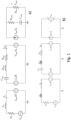
- Figure 1 shows the equivalent electrical model of a loudspeaker. Other more complex or more simplified representations are possible, e.g. in which parameters of the acoustic domain are not considered.
- the model includes three interdependent circuits which represent, from left to right, the electrical part, the mechanical part and the acoustic part of the transducer. This model accurately describes the behavior of the loudspeaker at frequencies lower than the first mode of vibrating of the diaphragm, that is, in the frequency band most affected by non-linear distortion phenomena.
- the electrical part of the model includes the series of the following elements:
- the mechanical part includes the series of the following elements:
- the acoustic part specialized for modeling the behavior of a closed volume, includes the following elements:
- the configuration of the acoustic part described here represents a loudspeaker in a closed box, variations to this configuration are known in the state of the art and easily derivable e.g. as expressed in figure 1b in which a model comprising a generic acoustic impedance is illustrated.
- the solution of the present invention consists in a method for processing a digital audio signal to alter the acoustic signal produced by a loudspeaker allowing to reduce the non-linear distortion generated by the loudspeaker or by imposing on the loudspeaker the linear or non-linear behavior of another speaker model.
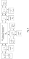
- Figure 2 shows the block diagram of the proposed solution consisting of a digital signal processor (Digital Signal Processor, DSP) configured to apply non-linear processing to the incoming audio signal, a digital-to-analog converter (digital-to-analog converter, DAC) configured to convert the digital output of the DSP into an analog signal, and an amplifier configured to amplify the analog signal to drive the loudspeaker.
- DSP Digital Signal Processor
- DAC digital-to-analog converter
- the DSP receives and processes a digital audio signal by applying a first and a second non-linear mathematical model: for example, the processor can apply a first non-linear digital filter to set a desired non-linear characteristic on the audio signal and, subsequently, to set another nonlinear compensating feature, e.g. linearizes, the non-linear characteristic of the speaker through the second mathematical model.
- the digital signal processor also includes an estimator that receives the amplified signal and estimates the constituent parameters of the non-linear digital filter that compensates for the non-linear characteristic of the loudspeaker. The presence of the estimator is optional, since the system can also operate using the nominal parameters of the loudspeaker.
- the pre-distorted signal is converted into an analog signal using a digital-to-analog converter (DAC) and subsequently amplified by means of an amplifier.
- the amplified signal drives the loudspeaker to produce an acoustic output signal.
- the loudspeaker includes a dynamic direct radiation loudspeaker operating in a closed box.
- the amplified signal is also used as the estimator input.
- the DSP is made by means of a hardware (a processor) which executes a suitable software loaded on a memory that can be read by the processor to perform the digital signal processing operations described below.
- the target nonlinear digital filter receives the digital audio signal in input, applies the nonlinear filter based on the parametric model of the loudspeaker to the input signal to produce a filtered digital signal and finally outputs the pre-distorted signal with the desidered non-linear characteristic, in order to be received and processed by downstream components.
- the non-linear target digital filter is implemented using a WDF system, described below.
- the non-linear target digital filter imposes on the audio signal a desired non-linear characteristic (target) which, for example, prevents overshooting of the transducer thus increasing its life time.
- the WDF implementation is based on the local constitutive relationships of the single-port elements that constitute the loudspeaker model in the continuous-time domain, as shown in the following table, in which the nomenclature of the elements refers to Figure 1a .
- R ms ⁇ 9 ( t ) R ms i 9 ( t )
- the dependent generators form two double-port elements.
- the first double-port element is an ideal rotator with a rotation ratio equal to Bl.
- V cm t I ms t Bl
- V me t I e t Bl
- Vcm(t) represents the counter-electromotive force in the electrical domain
- Vme(t) represents the force in the mechanical domain.
- the second double-port element is an ideal transformer with a transformation ratio equal to Sd.
- V ma t V out t S d
- I am t I ms t S d
- Vma ( t ) the reaction force impressed by the acoustic load on the mechanical domain
- Iam(t) the volumetric velocity in the acoustic domain.
- the overall system to numerical wave is shown in Figure 3 .
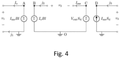
- the implementation of systems WDF containing multiport elements in the solution described here consists in connecting the dependent generators to a 3-port junction, as shown in the binary connection tree in Figure 4 .
- the three ports of the junction are numbered 1, 2 and 3 and are characterized by three pairs of Kirchhoff variables ⁇ ⁇ 1, j1 ⁇ , ⁇ ⁇ 2, j2 ⁇ , ⁇ ⁇ 3, j3 ⁇ .
- b 1 ⁇ 1 + Z 1 j 1
- a 1 ⁇ 1 ⁇ Z 1 j 1
- b 2 ⁇ 2 + Z 2 j 2
- a 2 ⁇ 2 ⁇ Z 2 j 2
- b 3 ⁇ 3 + Z 3 j 3
- a 3 ⁇ 3 ⁇ Z 3 j 3
- b 1 , b 2 and b 3 are the incident waves and a 1 , a 2 , a 3 are the waves reflected by the junction.
- the WDF implementation shown in Figure 4 allows to implement a direct computational flow, i.e. a computational flow that does not use iterative solvers.
- the computational flow consists of three phases, which are repeated for each instant of discrete time k.
- the status and output signals are computed from the incident and reflected waves computed by the computational flow described above.
- the input signal is represented by the variable ⁇ 1 .
- Some parameters of the speaker model are not time-invariant, but depend on the x ( t ) signal equivalent to the physical displacement of the coil in the transducer.
- the parameters Bl, K ms and L e are non-linear functions of the signal x ( t ). In the known art these functions are modeled as polynomials.
- the function Bl(x) is modeled as a Gaussian type function
- the L e (x) function is modeled as a sigmoid type function
- the K ms ( x ) function is modeled as a linear combination of exponential functions.
- the non-linear force factor is updated with each sample by evaluating the function Bl(x) in x ⁇ [k].
- L' e [k] represents the numerical derivative of L e (x(t))
- L e ′ k dL e x t dt
- K' ms [k] is the numerical derivative of K ms (x(t))
- K ms ′ k K ms ⁇ K ms ⁇ exp K ms ⁇ x ⁇ k + K ms ⁇ K m s ⁇ exp K m s ⁇ x ⁇ k .
- b 7 k ⁇ K ms a 7 k ⁇ 1 + b 7 k ⁇ 1 2
- Z 7 k K ms k T s 1 ⁇ 1 K ms ′ k a 7 k ⁇ 1 + b 7 k ⁇ 1 2 ,
- the inverse non-linear digital filter receives the output of the target non-linear digital filter at its input, applies the inverse non-linear filter based on the parametric model of the speaker to produce a filtered digital signal, and outputs the pre-distorted signal with the characteristic desired non-linear, compensating for the non-linear characteristic of the transducer, in order to be received and processed by the other components of the system.
- the inverse non-linear digital filter is implemented using a digital wave system, described below.
- the parameters of the inverse nonlinear digital filter are received by the estimator block, described later.
- the structure of the model before the inversion is the same as that of the first model with the addition of a null, as explained in more detail below.
- the parameters of the second model are suitably different from those of the first model to adapt to the construction characteristics of the speaker e.g. of the transducer.
- the proposed invention realizes the inverse system by manipulating the equivalent circuit of the speaker shown in Figure 1 . This manipulation, described below, allows you to create the inverse of any electrical circuit.
- the equivalent circuit of the transduction process shown in Figure 1a , can be manipulated by adding a theoretical circuit element, called nullor, to the ends of the resistor Ral to obtain the circuit depicted in Figure 5 .
- the nullor is defined as a two-gate theoretical circuit element, consisting of the series of a norator (shown with two continuous circles) and a nullator (shown with an ellipse).
- the nullator is a theoretical circuit element crossed by zero current and with zero voltage at its ends, while the norator is crossed by arbitrary current and has arbitrary voltage at its ends.
- the circuit of Figure 5 is further manipulated by replacing the norator with a voltage-controlled voltage generator, and replacing the source generator with the norator, for obtain the circuit of Figure 6 .
- a resistor is added in parallel to the norator and a resistor in series to the nullator; thanks to the circuit properties of the norator and nullator, it is observed that the addition of the resistors does not change the behavior of the circuit.
- circuits in Figure 5 and Figure 6 have the same topology, so they can be described by the same state function f(x, u, y) and by the same output function g(x, u, y), where x represents the state, u represents the input signal and y represents the output signal.
- Figure 7 shows the WDF reaction of the inverse system via a binary connection tree.
- the single-gate elements of the inverse system are characterized by the same scattering relationships already described in the previous section, as well as the and junctions.
- S R 2 ⁇ 1 ⁇ 2 Z 5 Bl ⁇ 2 Bl 2 + Z 2 Z 5 Bl S d Z 3 2 Bl 2 + Z 3 Z 5 S d 2 + Z 2 Z 5 BlS d Z 3 + 2 0 + 1 2 Z 2 S d Z 3 ⁇ 2 Z 2 S d Z 3 0 0 ⁇ 2 Z 5 Bl ⁇ 2 Bl 2 + Z 2 Z 5 Bl S d Z 3 2 Bl 2 + Z 3 Z 5 S d 2 + Z 2 Z 5 BlS d Z 3 + 2 0 0 ⁇ 1 + 2 0 0 0 0 ⁇ 2 Z 5 BlS d Z 3 + 2 0 0 ⁇ 1 + 2 0 0 0 ⁇ 2 Z 5 Bl ⁇ 2 Z 2 Z 5 Bl S d Z 3 2 Z 5 Z 3 + 1 .
- the status and output signals are computed from the incident and reflected waves computed by the computational flow described above.
- the input signal is represented by the variable v3.
- the parameters that describe the behavior of the transducer are variable over time depending on the electrical energy entering the transducer.
- the estimator is responsible for inferring the variation of these two parameters as a function of time, using the voltage Ve(t) and the current Ie(t) in input to the transducer as input signals.
- the amplified signal constitutes the transducer input that allows you to obtain the desired acoustic output.
- the amplified signal is also used as an input from the estimator.
Landscapes
- Physics & Mathematics (AREA)
- Engineering & Computer Science (AREA)
- Acoustics & Sound (AREA)
- Signal Processing (AREA)
- Circuit For Audible Band Transducer (AREA)
Description
- The present invention refers to a non-linear control method of an input signal for a loudspeaker based on numerical modeling of the transduction process.
- A loudspeaker is a transducer, i.e. a device capable of converting a physical quantity at its input, e.g. a current or a voltage, in another output by altering some characteristics that identify it. In particular, an electrical signal is converted into sound waves and the physical transduction mechanism can be described by a non-linear modeling to describe, for example, a harmonic distortion and a modulation of the electrical input signal due to the excursion of the moving parts and to the coil current
- Non-linearities of the transduction process are alleviated or controlled through three different methods:
- feedback-based methods;
- methods based on functional representation;
- physical model-based methods of the transduction process.
- The second family of methods is based on a representation of non-linear behavior using generic functional forms (Volterra, Hammerstein or Wiener systems) to estimate the variables of the system's state. The limit of this family of methods lies in the need to truncate the functional representation to limit the complexity of the estimation of the elements necessary to represent the terms above the second degree.
- The third family of methods is based on a non-linear physical model of the transduction process. This representation allows to overcome the disadvantages of methods based on functional representation, at the cost of an increase in computational complexity.
- Document 'Passive parametric modeling of dynamic loudspeakers', D. Franken et al., IEEE Transactions on speech and audio processing, NY vol. 9, no. 8, XP011054138 ISSN: 1063-6676 discloses a direct model of a loudspeaker without an wave digital filter inverse model. A direct model alone cannot linearize non-linearities such as inductance and/or the stiffness of the transducer and/or the force factor of the controlled generator used to simulate the coupling of the electric circuit model and the mechanical circuit model.
- Document 'Observer-based feedback linearization of dynamic loudspeakers with AC amplifiers', D. Franken et al. IEEE Transactions on speech and audio processing, NY vol. 13, no. 2, XP055816411 ISSN: 1063-6676 DOI: 10.1109 TSA.2004.841043discloses the generation of inverse mathematical models via a state observer but such approach does not produce a directly computable mathematical formula and the system of equations is solved by iterative algorithms. The cited wave digital filters are applied to estimate parameters of a direct model in real time.
- Document 'The realization of inverse system for circuits containing nullors with applications in chaos synchronization , LEUCIUC ADRIAN , INTERNATIONAL JOURNAL OF CIRCUIT THEORY AND APPLICATIONS, vol. 26, no. 11 January 1998 (1998-01-01), pages 1-12, XP055816246, ISSN: 0098-9886, DOI: 10.1002/(SICl)1097-007X(199801/02)26:1 1::AIDCTA9893.0.CO;2-B discloses a method for synthesizing the inverse system of a non-linear non-autonomous circuit containing nullors.
- Patent application
US 2003/142832 A1 discloses a technique for the adaptive estimation of loudspeaker parameters, including non-linear parameters, from the measurement of the current flowing through the loudspeaker, using a gradient descent algorithm. - The scope of the present invention is to at least partially solve the disadvantages mentioned above.
- The purpose of the present invention is achieved through a method for controlling a loudspeaker having an electromechanical force transducer and a diaphragm comprising the steps as defined in
claim 1. - The method of the present invention, belonging to the third family mentioned above, proposes a representation which reduces the computational complexity, e.g. avoiding iterative calculation algorithms of the state of the art, through WDFs, which are instead directly computable through e.g. a binary tree structure.
- In addition, a new method of inversion of the model based on the use of a nullor applied to a 'direct' electromechanical model of the loudspeaker is also advantageously introduced. This solves the main limitations existing today for physical model-based methods of the transduction process:
- the need to iteratively solve the non-linear model of the inverse system to make it computationally implementable;
- the strong dependence on the adaptive technique used to estimate the parameters of the nonlinear model.
- In particular, the non-linear model of the inverse system is obtained through the following steps:
- increase or amplify the model of the transduction process with a null, suitably connected so as not to modify the behavior of the model;
- derive the inverse equivalent model using a theorem known in the art [Leuciuc "The realization of inverse system for circuits containing nullors with applications in chaos synchronization", Int. J. Circ. Theor. Appl., 26, 1-12, 1998].
- The first direct model is preferably characterized by a desired property in the transduction process, such as one between the desired frequency response and / or a desired excursion-dependent force factor and / or a desired excursion-dependent mechanical stiffness and / or a desired inductance dependent on the excursion of the electromechanical force transducer.
- In particular, the first model limits the peaks of an input signal in order to avoid damage to the transducer, for example due to excessive movement, or to emulate a loudspeaker having known acoustic and / or electrical and / or mechanical characteristics known and different from those of the loudspeaker receiving the signal or the like.
- Preferably, the aforementioned non-linear electromechanical model includes loudspeaker parameters belonging to an electrical domain, at least one resistance and one impedance of a transducer coil; and to a mechanical domain, at least one elastic parameter such as stiffness, a damping and a moving mass of the transducer, the electrical and mechanical domain being coupled through a first conversion factor which relates an electromagnetic force applied to said moving mass with a counter electromotive force generated in the coil by the movement of the mass.
- In this way, it is possible to express important non-linearities, such as those of inductance, of the elastic parameter and of the electromechanical conversion factor.
- According to a preferred embodiment, the electromechanical model comprises at least one parameter of an acoustic domain, at least one acoustic impedance, the acoustic domain being coupled to the electrical and mechanical domains via a second conversion factor which relates to acoustic pressure waves generated from the diaphragm with a force applied by the transducer to the diaphragm.
- The inclusion of an acoustic domain in the electro-mechanical model allows to increase the accuracy of the model itself.
- Preferably the aforesaid method described above is combined with an adaptation step over time of one or more parameters of the electromechanical model based on an amplified analog output signal of the electromechanical model by means of an estimator.
- In this way, the model can take into account the evolution over time of the value of some parameters.
- Further characteristics and advantages of the present invention are indicated in the following description and in the claims.
-
-
Figures 1a, 1b show respective equivalent electric models of a loudspeaker, of whichFigure 1a shows a particular configuration of acoustic impedance which models the behavior of a closed volume, whileFigure 1b shows a generic configuration of acoustic impedance. -
Figure 2 shows the block diagram of the proposed system. -
Figure 3 shows the WDF implementation of the transducer model with the particular configuration of an acoustic impedance shown inFigure 1a -
Figure 4 shows a tri-port network implemented with a digital wave adapter of type. -
Figure 5 shows the equivalent circuit of the augmented transduction process with a nullor. -
Figure 6 shows the circuit equivalent to the reverse of the transduction process. -
Figure 7 shows the numerical wave embodiment of the inverse system; -
Figure 1 shows the equivalent electrical model of a loudspeaker. Other more complex or more simplified representations are possible, e.g. in which parameters of the acoustic domain are not considered. The model includes three interdependent circuits which represent, from left to right, the electrical part, the mechanical part and the acoustic part of the transducer. This model accurately describes the behavior of the loudspeaker at frequencies lower than the first mode of vibrating of the diaphragm, that is, in the frequency band most affected by non-linear distortion phenomena. - The electrical part of the model includes the series of the following elements:
- a voltage generator representing the voltage signal Vin at the loudspeaker input;
- a resistor with resistance Re representing the resistive part of the loudspeaker coil impedance;
- an inductor with inductance Le representing the purely inductive part of the loudspeaker coil impedance;
- a voltage generator controlled in current by the signal Ims weighed by the force factor Bl of the loudspeaker coil;
- The mechanical part includes the series of the following elements:
- an inductor with inductance Mms representing the mass of all moving parts of the transducer (including the volume of air integral to the diaphragm);
- a resistor with Rms resistance representing the mechanical resistance of the system;
- a capacitor with capacity Cms = 1 / Kms representing the mechanical compliance, inverse of the stiffness;
- a voltage generator controlled in current by the signal Ie weighted by the force factor Bl;
- a voltage generator controlled in voltage by the signal Vout weighed by the parameter Sd representing the effective surface of the radiator.
- The acoustic part, specialized for modeling the behavior of a closed volume, includes the following elements:
- a capacitor with capacity Ccab representing the compliance of the air contained in the closed volume;
- a resistor with resistance Rcab representing the acoustic resistance;
- a resistor with resistance Ral representing the air losses from the closed volume (to approximate the real behavior of a volume that is not perfectly sealed); according to a more general embodiment, the capacity and the two resistances indicated above can be modeled through an acoustic impedance;
- a current generator controlled in current by the signal Ims weighed by the parameter Sd.
- The configuration of the acoustic part described here represents a loudspeaker in a closed box, variations to this configuration are known in the state of the art and easily derivable e.g. as expressed in
figure 1b in which a model comprising a generic acoustic impedance is illustrated. - The solution of the present invention consists in a method for processing a digital audio signal to alter the acoustic signal produced by a loudspeaker allowing to reduce the non-linear distortion generated by the loudspeaker or by imposing on the loudspeaker the linear or non-linear behavior of another speaker model.
- Furthermore, it is necessary to consider the composition of the model in a purely explanatory way as indicated in
Figure 1a , since it is possible to apply known techniques for the realization of equivalent circuits to group the same parameters and the topology of the connections in a different way from that illustrated, leaving unchanged the functional characteristics. -
Figure 2 shows the block diagram of the proposed solution consisting of a digital signal processor (Digital Signal Processor, DSP) configured to apply non-linear processing to the incoming audio signal, a digital-to-analog converter (digital-to-analog converter, DAC) configured to convert the digital output of the DSP into an analog signal, and an amplifier configured to amplify the analog signal to drive the loudspeaker. - The DSP receives and processes a digital audio signal by applying a first and a second non-linear mathematical model: for example, the processor can apply a first non-linear digital filter to set a desired non-linear characteristic on the audio signal and, subsequently, to set another nonlinear compensating feature, e.g. linearizes, the non-linear characteristic of the speaker through the second mathematical model. According to a preferred embodiment of the invention, the digital signal processor also includes an estimator that receives the amplified signal and estimates the constituent parameters of the non-linear digital filter that compensates for the non-linear characteristic of the loudspeaker. The presence of the estimator is optional, since the system can also operate using the nominal parameters of the loudspeaker.
- The pre-distorted signal is converted into an analog signal using a digital-to-analog converter (DAC) and subsequently amplified by means of an amplifier. The amplified signal drives the loudspeaker to produce an acoustic output signal. The loudspeaker includes a dynamic direct radiation loudspeaker operating in a closed box. The amplified signal is also used as the estimator input. The DSP is made by means of a hardware (a processor) which executes a suitable software loaded on a memory that can be read by the processor to perform the digital signal processing operations described below.
- The target nonlinear digital filter receives the digital audio signal in input, applies the nonlinear filter based on the parametric model of the loudspeaker to the input signal to produce a filtered digital signal and finally outputs the pre-distorted signal with the desidered non-linear characteristic, in order to be received and processed by downstream components. The non-linear target digital filter is implemented using a WDF system, described below. The non-linear target digital filter imposes on the audio signal a desired non-linear characteristic (target) which, for example, prevents overshooting of the transducer thus increasing its life time.
- The WDF implementation is based on the local constitutive relationships of the single-port elements that constitute the loudspeaker model in the continuous-time domain, as shown in the following table, in which the nomenclature of the elements refers to
Figure 1a .Vin, Re υ 4(t) = Vin (t) + Rei 4(t) Le 
Kms 
Mms 
Rms υ 9(t) = Rmsi 9(t) Rcab υ 11(t) = Rcabiii (t) Ccab 
Ral υ 15(t) = R ali 15(t) - The dependent generators form two double-port elements. The first double-port element is an ideal rotator with a rotation ratio equal to Bl. In the continuous-time domain it is possible to write its constitutive relations

- The second double-port element is an ideal transformer with a transformation ratio equal to Sd. In the continuous-time domain its constitutive relations are

Figure 3 . - The implementation of systems WDF containing multiport elements in the solution described here consists in connecting the dependent generators to a 3-port junction, as shown in the binary connection tree in
Figure 4 . The three ports of the junction are numbered 1, 2 and 3 and are characterized by three pairs of Kirchhoff variables {υ1, j1}, {υ2, j2}, {υ3, j3}. The corresponding variables in the numerical wave domain are


- The scattering matrix of the junction S3 is

- The scattering matrix of the junction S2 is

- The scattering matrix of the junctionis


- Given the constitutive relationships shown above, the single-port elements of the loudspeaker model can be implemented as numerical wave elements as shown in the table below, where k denotes discrete time, Ts denotes sampling period and Fs = Ts -1 indicates the sampling frequency.
Definitions Scattering formulae V in, R e Z 4 = R e b 4[k] = V in[k] Le Z 5 = L e Fs b 5[k] = (b 5[k - 1] - a5[k - 1]) /2 Kms Z 7 = KmsTs b 7[k] = (b7 [k - 1] + a7 [k - 1]) /2 Mms Z 8 = MmsFs b 8[k] = (b8 [k - 1] + a8 [k - 1]) /2 Rms Z 9 = R ms b9 [k] = 0 Rcab Z 11 = Rcab b 11[k] = 0 C cab Z 12 = Ts /C cab b12[k] = (b12[k - 1] + a12[k - 1]) /2 R al Z 15 = R al b15[k] = 0 - While the following table shows the numerical wave implementation of the junctions, which uses the scattering matrices defined in Equations (6) - (10).
Definitions Scattering formulae 
Z 6 = Z 4 + Z 5, b 6 = a 1 [a 4, a 5, a 6] T = [b 4, b 5, b 6] T

Z 10 = Z7 + Z 8 + Z 9, b 10 = a 2 [a 7, a 8, a 9, a 10] T = [b 7, b 8, b 9, b 10] T

Z 13 = Z 11 + Z 12, b 13 = a 14 [a 11, a 12, a 13] T = [b 11, b 12, b 13] T


[a 14, a 15, a 16] T = [b 14, b 15, b 16] T

Z 1 = Z 6, Z 2 = Z 10, Z 3 = Z 16, b 1 = a 6, b 2 = a 10, b 3 = a 16 [a 1, a 2, a 3] T = [b1, b2, b3] T
- The WDF implementation shown in
Figure 4 allows to implement a direct computational flow, i.e. a computational flow that does not use iterative solvers. The computational flow consists of three phases, which are repeated for each instant of discrete time k. - 1) Direct scanning: from the leaves of the binary connection tree to the root. Along the computational path, the waves reflected by the linear elements are calculated by means of the scattering relations previously introduced; the waves are propagated through the junctions to the nonlinear elements.
- 2) Local nonlinear scattering at the root of the binary connection tree. Given the incident wave, calculated in
phase 1, the reflected wave is calculated using the constitutive relationship of the nonlinear element. - 3) Retrograde scan: from the root to the leaves of the binary connection tree. Along the computational path, the waves propagate through the junctions up to the linear elements; the waves incident to the linear elements are calculated using the scattering relations previously introduced.
- The status and output signals are computed from the incident and reflected waves computed by the computational flow described above.
- The input signal is represented by the variable υ1. In the discrete time domain, the signal analogous to the coil displacement can be estimated as


- The output signal Vout[k] equivalent to the pressure produced by the transducer is estimated as

- Some parameters of the speaker model are not time-invariant, but depend on the x(t) signal equivalent to the physical displacement of the coil in the transducer. In particular, the parameters Bl, Kms and Le are non-linear functions of the signal x(t). In the known art these functions are modeled as polynomials. This aspect is problematic since if the excursion x(t) exceeds the interval of

where L'e[k] represents the numerical derivative of Le(x(t))
- Considering the time-varying non-linear stiffness, the proposed numerical realization is
where K'ms[k] is the numerical derivative of Kms(x(t))

- The inverse non-linear digital filter receives the output of the target non-linear digital filter at its input, applies the inverse non-linear filter based on the parametric model of the speaker to produce a filtered digital signal, and outputs the pre-distorted signal with the characteristic desired non-linear, compensating for the non-linear characteristic of the transducer, in order to be received and processed by the other components of the system. The inverse non-linear digital filter is implemented using a digital wave system, described below. The parameters of the inverse nonlinear digital filter are received by the estimator block, described later. Preferably, the structure of the model before the inversion is the same as that of the first model with the addition of a null, as explained in more detail below. Instead, the parameters of the second model are suitably different from those of the first model to adapt to the construction characteristics of the speaker e.g. of the transducer.
- The proposed invention realizes the inverse system by manipulating the equivalent circuit of the speaker shown in
Figure 1 . This manipulation, described below, allows you to create the inverse of any electrical circuit. - The equivalent circuit of the transduction process, shown in
Figure 1a , can be manipulated by adding a theoretical circuit element, called nullor, to the ends of the resistor Ral to obtain the circuit depicted inFigure 5 . The nullor is defined as a two-gate theoretical circuit element, consisting of the series of a norator (shown with two continuous circles) and a nullator (shown with an ellipse). The nullator is a theoretical circuit element crossed by zero current and with zero voltage at its ends, while the norator is crossed by arbitrary current and has arbitrary voltage at its ends. The nullity, therefore, is characterized by the following constitutive relationship
- Considering the properties of the nullor, it can be observed that the circuits of
Figure 1a andFigure 5 are equivalent. - To obtain an inverse circuit that allows, with reference to
Figure 5 , to calculate Vin as a function of Vout, the circuit ofFigure 5 is further manipulated by replacing the norator with a voltage-controlled voltage generator, and replacing the source generator with the norator, for obtain the circuit ofFigure 6 . Furthermore, in the circuit ofFigure 6 , a resistor is added in parallel to the norator and a resistor in series to the nullator; thanks to the circuit properties of the norator and nullator, it is observed that the addition of the resistors does not change the behavior of the circuit. - The circuits in
Figure 5 and Figure 6 have the same topology, so they can be described by the same state function f(x, u, y) and by the same output function g(x, u, y), where x represents the state, u represents the input signal and y represents the output signal. By marking with a tilde the signals corresponding to the circuit ofFigure 6 , and assuming that the circuits ofFigure 5 and Figure 6 admit a single solution, then the output equation g(x, u, y)=0 which represents the circuit ofFigure 5 has unique solution y=h(x, u), and the output equation g (x_tilde, u_tilde, y)=0 which represents the circuit ofFigure 6 has unique solution u_tilde=h^(- 1)( x_tilde, y), for each real-valued x and x_tilde state. It follows that if the initial states coincide, e.g. x (0) = x_tilde (0), then u=u_tilde, ie the circuit inFigure 6 realizes the inverse of the circuit inFigure 5 . - This result is known in the literature. C.f.r. A. Leuciuc, "The realization of inverse system for circuits containing nullors with applications in chaos synchronization", Int. J. Circ. Theor. Appl., 26, 1-12 (1998).
-
Figure 7 shows the WDF reaction of the inverse system via a binary connection tree. The single-gate elements of the inverse system are characterized by the same scattering relationships already described in the previous section, as well as the and junctions. - The scattering matrix of the junction, which in this case (considering the different topology) has five gates, is defined as

- The status and output signals are computed from the incident and reflected waves computed by the computational flow described above.
- The input signal is represented by the variable v3. The output signal Vout[k] equivalent to the transducer input voltage which cancels its non-linear behavior is Vout[k] = v1.
- It is known that the parameters that describe the behavior of the transducer are variable over time depending on the electrical energy entering the transducer. In particular, the parameters most sensitive to variations are the electrical resistance Re and the Kms value (x = 0) which describes the stiffness at rest of the transducer suspensions. The estimator is responsible for inferring the variation of these two parameters as a function of time, using the voltage Ve(t) and the current Ie(t) in input to the transducer as input signals.
- The estimation of Re(t) and Kms(x = 0, t) is performed by the following algorithm.
- 1. Estimate of Re. We consider the estimate R^e and two perturbations of the estimate R^e ± δR . The non-linear target digital filter is used to predict the current entering the transducer. The three estimated currents are compared with the measured current. The resistance value that returns the smallest error between the measured current and the estimated current is selected.
- 2. Estimate of Kms(0). We consider the K^ms (0) estimate and two perturbations of the K^ms (0) ± δK estimate. The non-linear target digital filter is used to predict the current entering the transducer. The three estimated currents are compared with the measured current. The stiffness value is selected which gives the smallest error between the measured current and the estimated current.
- The pre-distorted signal with the desired non-linear characteristic, compensating for the non-linear characteristic of the transducer and adapting the parameters Re and Kms (x = 0) is converted into the analog domain by a digital / analog converter and then amplified with a audio amplifier. The amplified signal constitutes the transducer input that allows you to obtain the desired acoustic output. The amplified signal is also used as an input from the estimator.
- Finally, it is clear that it is possible to make changes or variations to the method described and illustrated here without departing from the scope of protection as defined by the attached claims.
Claims (7)
- A method of controlling a loudspeaker having an electromechanical force transducer and a diaphragm comprising the steps of:- providing a non-linear electromechanical model (FT) configured to apply one or more desired conditions to a loudspeaker input digital audio signal;- provide an inverse non-linear electromechanical (FI) model of the electromechanical force transducer configured to receive a signal processed by the non-linear electromechanical model (FT) and to compensate, preferably linearize, at least one mechanical and / or electrical and / or electromechanical non-linearity of a transducer coil;- convert a digital output signal of the inverse non-linear electromechanical model (FI) into an analog signal for the electromechanical force transducer,wherein the digital output signal comprises a voltage signal representative of a displacement of the electromechanical force transducer to emit sounds by an action of the electromechanical force transducer on the diaphragm, characterized in that said inverse non-linear electromechanical model (FI) is a digital wave filter (WDF) model to provide a directly computable function of the loudspeaker input digital audio signal for the electromechanical force transducer.
- Method according to claim 1, wherein said inverse non-linear electromechanical model (FI) is obtained starting from the non-linear electromechanical model (FT) having a form of a direct electromechanical model comprising a nullor.
- Method according to claim 1 or 2, wherein the one or more desired conditions comprise at least one of a desired frequency response condition and / or a force factor dependent on a desired excursion and / or a mechanical stiffness dependent on the desired excursion and / or an inductance depending on the desired excursion of the electromechanical force transducer.
- Method according to any one of the preceding claims, wherein the aforementioned inverse non-linear electromechanical model (FI) includes parameters of the loudspeaker belonging to an electrical domain, such as at least a resistance and an impedance of the transducer coil; and to a mechanical domain, such as at least one elastic parameter such as a stiffness and a moving mass of the electromechanical force transducer, the electrical and mechanical domain being coupled through a first conversion factor based on a first current-controlled voltage generator and a second current-controlled voltage generator to relate an electromagnetic force applied to said moving mass with a counter-electromotive force generated in the transducer coil by the movement of the moving mass.
- Method according to claim 4, wherein the inverse non-linear electromechanical model (FI) comprises at least one parameter of an acoustic domain, such as at least one acoustic impedance, the acoustic domain being coupled to the electrical and mechanical domains via a second conversion factor which relates acoustic waves of pressure generated by the diaphragm with a force applied by the electromechanical force transducer to the diaphragm.
- Method according to clam 5, wherein the second conversion factor is based on a voltage-controlled voltage generator and a current-controlled current generator.
- Electronic control unit for a loudspeaker having an electromechanical force transducer and a diaphragm programmed for:running a non-linear electromechanical model (FT) configured to apply one or more desired conditions to a loudspeaker input digital audio signal;performing an inverse non-linear electromechanical (FI) model of the electromechanical force transducer configured to receive a signal processed by the non-linear electromechanical model (FT) and to compensate, preferably linearize, at least one mechanical and / or electrical and / or electromechanical non-linearity of a transducer coil;convert a digital output signal of the inverse non-linear electromechanical model (FI) into an analog signal for the electromechanical force transducer,wherein the digital output signal comprises a voltage signal representative of a displacement of the electromechanical force transducer to emit sounds by an action of the electromechanical force transducer on the diaphragm, characterized in that the inverse non-linear electromechanical model (FI) is a digital wave filter (WDF) model to provide a directly computable function of the loudspeaker input digital audio signal for the electromechanical force transducer.
Applications Claiming Priority (1)
| Application Number | Priority Date | Filing Date | Title |
|---|---|---|---|
| IT202000024175 | 2020-10-14 |
Publications (3)
| Publication Number | Publication Date |
|---|---|
| EP3985995A1 EP3985995A1 (en) | 2022-04-20 |
| EP3985995B1 true EP3985995B1 (en) | 2024-07-31 |
| EP3985995C0 EP3985995C0 (en) | 2024-07-31 |
Family
ID=73793760
Family Applications (1)
| Application Number | Title | Priority Date | Filing Date |
|---|---|---|---|
| EP21202541.5A Active EP3985995B1 (en) | 2020-10-14 | 2021-10-13 | Method for the non-linear control of an input signal for a loudspeaker |
Country Status (4)
| Country | Link |
|---|---|
| US (1) | US11871203B2 (en) |
| EP (1) | EP3985995B1 (en) |
| CN (1) | CN116508329A (en) |
| WO (1) | WO2022079649A1 (en) |
Families Citing this family (2)
| Publication number | Priority date | Publication date | Assignee | Title |
|---|---|---|---|---|
| US20250106573A1 (en) * | 2021-12-22 | 2025-03-27 | Meta Platforms Technologies, Llc | Loudspeaker system identification and dynamic updating of loudspeaker system parameters |
| JP2024060211A (en) * | 2022-10-19 | 2024-05-02 | アルプスアルパイン株式会社 | Speaker output characteristic correction system and audio system |
Family Cites Families (7)
| Publication number | Priority date | Publication date | Assignee | Title |
|---|---|---|---|---|
| DE19960979A1 (en) * | 1999-12-17 | 2001-07-05 | Bosch Gmbh Robert | Adaptive method for determining speaker parameters |
| US7826625B2 (en) * | 2004-12-21 | 2010-11-02 | Ntt Docomo, Inc. | Method and apparatus for frame-based loudspeaker equalization |
| FR2995167B1 (en) * | 2012-08-30 | 2014-11-14 | Parrot | METHOD FOR PROCESSING AN AUDIO SIGNAL WITH MODELING OF THE GLOBAL RESPONSE OF THE ELECTRODYNAMIC SPEAKER |
| US10015593B2 (en) * | 2014-03-03 | 2018-07-03 | University Of Utah | Digital signal processor for audio extensions and correction of nonlinear distortions in loudspeakers |
| US9578412B2 (en) * | 2014-06-27 | 2017-02-21 | Apple Inc. | Mass loaded earbud with vent chamber |
| GB2556015B (en) * | 2016-04-29 | 2018-10-17 | Cirrus Logic Int Semiconductor Ltd | Audio Signals |
| GB2549805B (en) * | 2016-04-29 | 2018-10-03 | Cirrus Logic Int Semiconductor Ltd | Audio signals |
-
2021
- 2021-10-13 EP EP21202541.5A patent/EP3985995B1/en active Active
- 2021-10-14 WO PCT/IB2021/059442 patent/WO2022079649A1/en not_active Ceased
- 2021-10-14 US US17/501,328 patent/US11871203B2/en active Active
- 2021-10-14 CN CN202180070272.7A patent/CN116508329A/en active Pending
Also Published As
| Publication number | Publication date |
|---|---|
| US20220116713A1 (en) | 2022-04-14 |
| WO2022079649A1 (en) | 2022-04-21 |
| US11871203B2 (en) | 2024-01-09 |
| EP3985995C0 (en) | 2024-07-31 |
| EP3985995A1 (en) | 2022-04-20 |
| CN116508329A (en) | 2023-07-28 |
Similar Documents
| Publication | Publication Date | Title |
|---|---|---|
| US9232311B2 (en) | Method for processing an audio signal with modeling of the overall response of the electrodynamic loudspeaker | |
| CN102843633B (en) | The control of loudspeaker output | |
| CN103327437B (en) | A loudspeaker drive circuit for determining loudspeaker characteristics and/or diagnostics | |
| CN102742300B (en) | Control of a loudspeaker output | |
| JP4778001B2 (en) | Method and apparatus for frame-based speaker equalization | |
| US10015593B2 (en) | Digital signal processor for audio extensions and correction of nonlinear distortions in loudspeakers | |
| US9924267B2 (en) | Device for controlling a loudspeaker | |
| JP5139321B2 (en) | Digital PWM amplifier with simulation-based feedback | |
| US6351740B1 (en) | Method and system for training dynamic nonlinear adaptive filters which have embedded memory | |
| US11871203B2 (en) | Method for the non-linear control of an input signal for a loudspeaker | |
| Yeh et al. | Numerical methods for simulation of guitar distortion circuits | |
| Yeh | Digital implementation of musical distortion circuits by analysis and simulation | |
| Ghasemi et al. | Nonlinear Thf‐Fxlms algorithm for active noise control with loudspeaker nonlinearity | |
| CN101247671A (en) | Optimal estimation of converter parameters | |
| Bernardini et al. | Loudspeaker virtualization–Part I: Digital modeling and implementation of the nonlinear transducer equivalent circuit | |
| Chang et al. | Inverse filtering of a loudspeaker and room acoustics using time‐delay neural networks | |
| CN116151009B (en) | A Frequency Response Identification Method for Ultra-precision Motion System | |
| CN113382347B (en) | Parameter identification method for nonlinear fractional order loudspeaker | |
| CN111326134A (en) | Active noise reduction method based on EMFNL filter offline modeling secondary channel | |
| CN103792850A (en) | Method for establishing equivalent model of radar servo system | |
| Chen et al. | Parameter identification of systems with preload nonlinearities based on the finite impulse response model and negative gradient search | |
| HK40096605A (en) | Method for non-linear control of input signal for loudspeaker | |
| Falaize et al. | Passive simulation of electrodynamic loudspeakers for guitar amplifiers: a port-Hamiltonian approach | |
| Lashkari et al. | Exact linearization of Wiener and Hammerstein systems loudspeaker linearization | |
| Iwai et al. | Modified second-order nonlinear infinite impulse response (IIR) filter for equalizing frequency response and compensating nonlinear distortions of electrodynamic loudspeaker |
Legal Events
| Date | Code | Title | Description |
|---|---|---|---|
| PUAI | Public reference made under article 153(3) epc to a published international application that has entered the european phase |
Free format text: ORIGINAL CODE: 0009012 |
|
| STAA | Information on the status of an ep patent application or granted ep patent |
Free format text: STATUS: THE APPLICATION HAS BEEN PUBLISHED |
|
| AK | Designated contracting states |
Kind code of ref document: A1 Designated state(s): AL AT BE BG CH CY CZ DE DK EE ES FI FR GB GR HR HU IE IS IT LI LT LU LV MC MK MT NL NO PL PT RO RS SE SI SK SM TR |
|
| STAA | Information on the status of an ep patent application or granted ep patent |
Free format text: STATUS: REQUEST FOR EXAMINATION WAS MADE |
|
| 17P | Request for examination filed |
Effective date: 20221020 |
|
| RBV | Designated contracting states (corrected) |
Designated state(s): AL AT BE BG CH CY CZ DE DK EE ES FI FR GB GR HR HU IE IS IT LI LT LU LV MC MK MT NL NO PL PT RO RS SE SI SK SM TR |
|
| RAP3 | Party data changed (applicant data changed or rights of an application transferred) |
Owner name: POLITECNICO DI MILANO - DIPARTIMENTO DI ELETTRONICA, INFORMAZIONE E BIOINGEGNERIA Owner name: ELETTROMEDA S.P.A. |
|
| RAP3 | Party data changed (applicant data changed or rights of an application transferred) |
Owner name: POLITECNICO DI MILANO - DIPARTIMENTO DI ELETTRONICA, INFORMAZIONE E BIOINGEGNERIA Owner name: ELETTROMEDIA S.P.A. |
|
| RAP1 | Party data changed (applicant data changed or rights of an application transferred) |
Owner name: ELETTROMEDIA S.P.A. |
|
| GRAP | Despatch of communication of intention to grant a patent |
Free format text: ORIGINAL CODE: EPIDOSNIGR1 |
|
| STAA | Information on the status of an ep patent application or granted ep patent |
Free format text: STATUS: GRANT OF PATENT IS INTENDED |
|
| INTG | Intention to grant announced |
Effective date: 20240318 |
|
| GRAS | Grant fee paid |
Free format text: ORIGINAL CODE: EPIDOSNIGR3 |
|
| GRAA | (expected) grant |
Free format text: ORIGINAL CODE: 0009210 |
|
| STAA | Information on the status of an ep patent application or granted ep patent |
Free format text: STATUS: THE PATENT HAS BEEN GRANTED |
|
| AK | Designated contracting states |
Kind code of ref document: B1 Designated state(s): AL AT BE BG CH CY CZ DE DK EE ES FI FR GB GR HR HU IE IS IT LI LT LU LV MC MK MT NL NO PL PT RO RS SE SI SK SM TR |
|
| REG | Reference to a national code |
Ref country code: CH Ref legal event code: EP Ref country code: GB Ref legal event code: FG4D |
|
| REG | Reference to a national code |
Ref country code: DE Ref legal event code: R096 Ref document number: 602021016406 Country of ref document: DE |
|
| REG | Reference to a national code |
Ref country code: IE Ref legal event code: FG4D |
|
| U01 | Request for unitary effect filed |
Effective date: 20240809 |
|
| U07 | Unitary effect registered |
Designated state(s): AT BE BG DE DK EE FI FR IT LT LU LV MT NL PT RO SE SI Effective date: 20240917 |
|
| U20 | Renewal fee for the european patent with unitary effect paid |
Year of fee payment: 4 Effective date: 20241018 |
|
| PG25 | Lapsed in a contracting state [announced via postgrant information from national office to epo] |
Ref country code: NO Free format text: LAPSE BECAUSE OF FAILURE TO SUBMIT A TRANSLATION OF THE DESCRIPTION OR TO PAY THE FEE WITHIN THE PRESCRIBED TIME-LIMIT Effective date: 20241031 |
|
| PG25 | Lapsed in a contracting state [announced via postgrant information from national office to epo] |
Ref country code: PL Free format text: LAPSE BECAUSE OF FAILURE TO SUBMIT A TRANSLATION OF THE DESCRIPTION OR TO PAY THE FEE WITHIN THE PRESCRIBED TIME-LIMIT Effective date: 20240731 Ref country code: GR Free format text: LAPSE BECAUSE OF FAILURE TO SUBMIT A TRANSLATION OF THE DESCRIPTION OR TO PAY THE FEE WITHIN THE PRESCRIBED TIME-LIMIT Effective date: 20241101 |
|
| PG25 | Lapsed in a contracting state [announced via postgrant information from national office to epo] |
Ref country code: IS Free format text: LAPSE BECAUSE OF FAILURE TO SUBMIT A TRANSLATION OF THE DESCRIPTION OR TO PAY THE FEE WITHIN THE PRESCRIBED TIME-LIMIT Effective date: 20241130 |
|
| PG25 | Lapsed in a contracting state [announced via postgrant information from national office to epo] |
Ref country code: HR Free format text: LAPSE BECAUSE OF FAILURE TO SUBMIT A TRANSLATION OF THE DESCRIPTION OR TO PAY THE FEE WITHIN THE PRESCRIBED TIME-LIMIT Effective date: 20240731 |
|
| PG25 | Lapsed in a contracting state [announced via postgrant information from national office to epo] |
Ref country code: RS Free format text: LAPSE BECAUSE OF FAILURE TO SUBMIT A TRANSLATION OF THE DESCRIPTION OR TO PAY THE FEE WITHIN THE PRESCRIBED TIME-LIMIT Effective date: 20241031 Ref country code: ES Free format text: LAPSE BECAUSE OF FAILURE TO SUBMIT A TRANSLATION OF THE DESCRIPTION OR TO PAY THE FEE WITHIN THE PRESCRIBED TIME-LIMIT Effective date: 20240731 |
|
| PG25 | Lapsed in a contracting state [announced via postgrant information from national office to epo] |
Ref country code: RS Free format text: LAPSE BECAUSE OF FAILURE TO SUBMIT A TRANSLATION OF THE DESCRIPTION OR TO PAY THE FEE WITHIN THE PRESCRIBED TIME-LIMIT Effective date: 20241031 Ref country code: PL Free format text: LAPSE BECAUSE OF FAILURE TO SUBMIT A TRANSLATION OF THE DESCRIPTION OR TO PAY THE FEE WITHIN THE PRESCRIBED TIME-LIMIT Effective date: 20240731 Ref country code: NO Free format text: LAPSE BECAUSE OF FAILURE TO SUBMIT A TRANSLATION OF THE DESCRIPTION OR TO PAY THE FEE WITHIN THE PRESCRIBED TIME-LIMIT Effective date: 20241031 Ref country code: IS Free format text: LAPSE BECAUSE OF FAILURE TO SUBMIT A TRANSLATION OF THE DESCRIPTION OR TO PAY THE FEE WITHIN THE PRESCRIBED TIME-LIMIT Effective date: 20241130 Ref country code: HR Free format text: LAPSE BECAUSE OF FAILURE TO SUBMIT A TRANSLATION OF THE DESCRIPTION OR TO PAY THE FEE WITHIN THE PRESCRIBED TIME-LIMIT Effective date: 20240731 Ref country code: GR Free format text: LAPSE BECAUSE OF FAILURE TO SUBMIT A TRANSLATION OF THE DESCRIPTION OR TO PAY THE FEE WITHIN THE PRESCRIBED TIME-LIMIT Effective date: 20241101 Ref country code: ES Free format text: LAPSE BECAUSE OF FAILURE TO SUBMIT A TRANSLATION OF THE DESCRIPTION OR TO PAY THE FEE WITHIN THE PRESCRIBED TIME-LIMIT Effective date: 20240731 |
|
| PG25 | Lapsed in a contracting state [announced via postgrant information from national office to epo] |
Ref country code: SM Free format text: LAPSE BECAUSE OF FAILURE TO SUBMIT A TRANSLATION OF THE DESCRIPTION OR TO PAY THE FEE WITHIN THE PRESCRIBED TIME-LIMIT Effective date: 20240731 |
|
| PG25 | Lapsed in a contracting state [announced via postgrant information from national office to epo] |
Ref country code: CZ Free format text: LAPSE BECAUSE OF FAILURE TO SUBMIT A TRANSLATION OF THE DESCRIPTION OR TO PAY THE FEE WITHIN THE PRESCRIBED TIME-LIMIT Effective date: 20240731 |
|
| PG25 | Lapsed in a contracting state [announced via postgrant information from national office to epo] |
Ref country code: SK Free format text: LAPSE BECAUSE OF FAILURE TO SUBMIT A TRANSLATION OF THE DESCRIPTION OR TO PAY THE FEE WITHIN THE PRESCRIBED TIME-LIMIT Effective date: 20240731 |
|
| REG | Reference to a national code |
Ref country code: CH Ref legal event code: PL |
|
| PLBE | No opposition filed within time limit |
Free format text: ORIGINAL CODE: 0009261 |
|
| STAA | Information on the status of an ep patent application or granted ep patent |
Free format text: STATUS: NO OPPOSITION FILED WITHIN TIME LIMIT |
|
| PG25 | Lapsed in a contracting state [announced via postgrant information from national office to epo] |
Ref country code: MC Free format text: LAPSE BECAUSE OF FAILURE TO SUBMIT A TRANSLATION OF THE DESCRIPTION OR TO PAY THE FEE WITHIN THE PRESCRIBED TIME-LIMIT Effective date: 20240731 |
|
| 26N | No opposition filed |
Effective date: 20250501 |
|
| PG25 | Lapsed in a contracting state [announced via postgrant information from national office to epo] |
Ref country code: CH Free format text: LAPSE BECAUSE OF NON-PAYMENT OF DUE FEES Effective date: 20241031 |
|
| PG25 | Lapsed in a contracting state [announced via postgrant information from national office to epo] |
Ref country code: IE Free format text: LAPSE BECAUSE OF NON-PAYMENT OF DUE FEES Effective date: 20241013 |
|
| U20 | Renewal fee for the european patent with unitary effect paid |
Year of fee payment: 5 Effective date: 20251024 |
|
| PGFP | Annual fee paid to national office [announced via postgrant information from national office to epo] |
Ref country code: GB Payment date: 20251024 Year of fee payment: 5 |
|
| PG25 | Lapsed in a contracting state [announced via postgrant information from national office to epo] |
Ref country code: CY Free format text: LAPSE BECAUSE OF FAILURE TO SUBMIT A TRANSLATION OF THE DESCRIPTION OR TO PAY THE FEE WITHIN THE PRESCRIBED TIME-LIMIT; INVALID AB INITIO Effective date: 20211013 |
|
| PG25 | Lapsed in a contracting state [announced via postgrant information from national office to epo] |
Ref country code: HU Free format text: LAPSE BECAUSE OF FAILURE TO SUBMIT A TRANSLATION OF THE DESCRIPTION OR TO PAY THE FEE WITHIN THE PRESCRIBED TIME-LIMIT; INVALID AB INITIO Effective date: 20211013 |