EP3985924A1 - Multicast method, apparatus, device and system for multicast group of virtual network group - Google Patents
Multicast method, apparatus, device and system for multicast group of virtual network group Download PDFInfo
- Publication number
- EP3985924A1 EP3985924A1 EP20825817.8A EP20825817A EP3985924A1 EP 3985924 A1 EP3985924 A1 EP 3985924A1 EP 20825817 A EP20825817 A EP 20825817A EP 3985924 A1 EP3985924 A1 EP 3985924A1
- Authority
- EP
- European Patent Office
- Prior art keywords
- multicast
- interface
- reference point
- group
- upf
- Prior art date
- Legal status (The legal status is an assumption and is not a legal conclusion. Google has not performed a legal analysis and makes no representation as to the accuracy of the status listed.)
- Granted
Links
Images








Classifications
-
- H—ELECTRICITY
- H04—ELECTRIC COMMUNICATION TECHNIQUE
- H04W—WIRELESS COMMUNICATION NETWORKS
- H04W4/00—Services specially adapted for wireless communication networks; Facilities therefor
- H04W4/06—Selective distribution of broadcast services, e.g. multimedia broadcast multicast service [MBMS]; Services to user groups; One-way selective calling services
-
- H—ELECTRICITY
- H04—ELECTRIC COMMUNICATION TECHNIQUE
- H04L—TRANSMISSION OF DIGITAL INFORMATION, e.g. TELEGRAPHIC COMMUNICATION
- H04L12/00—Data switching networks
- H04L12/02—Details
- H04L12/16—Arrangements for providing special services to substations
- H04L12/18—Arrangements for providing special services to substations for broadcast or conference, e.g. multicast
- H04L12/185—Arrangements for providing special services to substations for broadcast or conference, e.g. multicast with management of multicast group membership
-
- H—ELECTRICITY
- H04—ELECTRIC COMMUNICATION TECHNIQUE
- H04L—TRANSMISSION OF DIGITAL INFORMATION, e.g. TELEGRAPHIC COMMUNICATION
- H04L12/00—Data switching networks
- H04L12/02—Details
- H04L12/16—Arrangements for providing special services to substations
- H04L12/18—Arrangements for providing special services to substations for broadcast or conference, e.g. multicast
- H04L12/189—Arrangements for providing special services to substations for broadcast or conference, e.g. multicast in combination with wireless systems
-
- H—ELECTRICITY
- H04—ELECTRIC COMMUNICATION TECHNIQUE
- H04L—TRANSMISSION OF DIGITAL INFORMATION, e.g. TELEGRAPHIC COMMUNICATION
- H04L12/00—Data switching networks
- H04L12/28—Data switching networks characterised by path configuration, e.g. LAN [Local Area Networks] or WAN [Wide Area Networks]
- H04L12/46—Interconnection of networks
- H04L12/4633—Interconnection of networks using encapsulation techniques, e.g. tunneling
-
- H—ELECTRICITY
- H04—ELECTRIC COMMUNICATION TECHNIQUE
- H04L—TRANSMISSION OF DIGITAL INFORMATION, e.g. TELEGRAPHIC COMMUNICATION
- H04L12/00—Data switching networks
- H04L12/28—Data switching networks characterised by path configuration, e.g. LAN [Local Area Networks] or WAN [Wide Area Networks]
- H04L12/46—Interconnection of networks
- H04L12/4641—Virtual LANs, VLANs, e.g. virtual private networks [VPN]
-
- H—ELECTRICITY
- H04—ELECTRIC COMMUNICATION TECHNIQUE
- H04L—TRANSMISSION OF DIGITAL INFORMATION, e.g. TELEGRAPHIC COMMUNICATION
- H04L67/00—Network arrangements or protocols for supporting network services or applications
- H04L67/14—Session management
-
- H—ELECTRICITY
- H04—ELECTRIC COMMUNICATION TECHNIQUE
- H04L—TRANSMISSION OF DIGITAL INFORMATION, e.g. TELEGRAPHIC COMMUNICATION
- H04L67/00—Network arrangements or protocols for supporting network services or applications
- H04L67/14—Session management
- H04L67/146—Markers for unambiguous identification of a particular session, e.g. session cookie or URL-encoding
-
- H—ELECTRICITY
- H04—ELECTRIC COMMUNICATION TECHNIQUE
- H04W—WIRELESS COMMUNICATION NETWORKS
- H04W4/00—Services specially adapted for wireless communication networks; Facilities therefor
- H04W4/06—Selective distribution of broadcast services, e.g. multimedia broadcast multicast service [MBMS]; Services to user groups; One-way selective calling services
- H04W4/08—User group management
Definitions
- the disclosure relates to the communications field, and in particular, to a multicast method, apparatus, device, and system for a multicast group of a virtual network group.
- Ethernet communication is introduced in a 5G system.
- a definition of a 5G virtual network group (5G VN group) that supports IP and Ethernet communication is introduced in Release 16 of a New Radio (NR) system.
- NR New Radio
- UPF user plane function
- the 5G VN group in the related art cannot implement a one-to-multiple communication solution.
- Embodiments of the disclosure provide a multicast method, apparatus, device, and system for a multicast group of a virtual network group. At least two internal broadcast interfaces are provided in a UPF, and a target internal broadcast interface in the at least two internal broadcast interfaces is used for transmitting a multicast data packet to all members or all local members of the multicast group, to implement a one-to-multiple communication solution in the virtual network group.
- the technical solutions are as follows:
- a multicast method for a multicast group of a virtual network group is provided, where the method is applicable to a UPF, and the method includes:
- a multicast method for a multicast group of a virtual network group is provided, where the method is applicable to a session management function (SMF), and the method includes:
- a multicast apparatus for a multicast group of a virtual network group includes:
- a multicast apparatus for a multicast group of a virtual network group includes:
- a computer device where a UPF is running on the computer device, and the computer device includes a processor and a memory, where the memory stores a computer program, and the computer program is loaded and executed by the processor to implement the multicast method for a multicast group of a virtual network group according to the foregoing aspect.
- a computer device where an SMF is running on the computer device, and the computer device includes a processor and a memory, where the memory stores a computer program, and the computer program is loaded and executed by the processor to implement the multicast method for a multicast group of a virtual network group according to the foregoing aspect.
- a computer-readable storage medium storing at least one instruction, at least one program, a code set, or an instruction set, the at least one instruction, the at least one program, the code set, or the instruction set being loaded and executed by a processor to implement the multicast method for a multicast group of a virtual network group according to the foregoing aspect.
- a UPF when receiving a multicast data packet transmitted by a member in a virtual network group, a UPF transmits the multicast data packet to a target internal multicast interface in the at least two internal multicast interfaces, and transmits the multicast data packet to all multicast group members or all local multicast group members of a multicast group through the target internal multicast interface, so that one-to-multiple network communication is implemented in the virtual network group, and a multicast function is implemented in the virtual network group.
- FIG. 1 shows a block diagram of a 5G communications system according to an example embodiment of the present disclosure.
- the communications system may be a 5G New Radio (NR) system, or includes a 5G system based on an Evolved Universal Mobile Telecommunications System (UMTS) Terrestrial Radio Access Network (eUTRAN) and a subsequent evolved system of the 5G system.
- the communications system is defined to support data connections and services so that technologies such as network function virtualization (NFV) and software-defined networking (SDN) may be used in network deployment.
- the communications system mainly includes a network function (NF), and is deployed as required by using distributed functions. The addition and withdrawal of a new network function do not affect the overall network functions.
- the communications system includes user equipment (UE) (named for a mobile terminal by 3GPP) (UE), a (radio) access network ((R)AN), a user plane function (UPF), a data network (DN), and control plane functions.
- UE user equipment
- R radio access network
- UPF
- the control plane functions include an access and mobility management function (AMF), a session management function (SMF), a policy control function (PCF), and unified data management (UDM).
- AMF access and mobility management function
- SMF session management function
- PCF policy control function
- UDM unified data management
- the UE communicates with the RAN through an air interface.
- the RAN communicates with the UPF through a first reference point N3.
- Two UPFs communicate with each other through a second reference point N9.
- a protocol data unit session anchor user plane function (PSA UPF) communicates with the DN through a third reference point N6.
- UEs There may be a plurality of UEs, RANs, UPFs, and DNs.
- some UPFs are PSA UPFs of the UE.
- Two PSA UPFs communicate with each other through a fourth reference point N19 (not shown in FIG. 1 ).
- the UE communicates with the AMF through a fifth reference point N1.
- the RAN communicates with the AMF through a seventh reference point N2.
- the UPF communicates with the SMF through an eighth reference point N4.
- the network architecture shown in FIG. 1 includes the following reference points:
- the network architecture shown in FIG. 1 includes the following service-based interfaces:
- Communication of a virtual network group includes one-to-one communication and one-to-multiple communication.
- One-to-one communication supports forwarding unicast communication between two UEs in a virtual network group or between a UE and a device on a DN.
- One-to-multiple communication supports forwarding of multicast data from a UE (or a device on a DN) to a plurality of UEs in a virtual network group and devices on the DN, or forwarding of multicast data from a UE (or a device on a DN) to all UEs in a multicast group and devices on the DN.
- Multicast communication means that multicast data transmitted by a member (UE or device) in a virtual network group needs to be transferred to each multicast group member of a corresponding multicast group. Based on the communications system shown in FIG. 1 , an embodiment of the disclosure supports three multicast communication manners.
- multicast group members of a multicast group include two UEs connected to the same PSA UPF
- multicast data between the two UEs is directly exchanged inside the PSA UPF instead of being transmitted beyond the third reference point N6, and is then returned by an external router or a switch.
- UE1 communicates with RANI, and RANI communicates with intermediate UPF1; and UE2 communicates with RAN2, and RAN2 communicates with UPF2. Both UE1 and UE2 are connected to the same PSA UPF.
- the multicast data packet is directly exchanged inside the PSA UPF, so that the multicast data packet is transmitted to UE2, and the multicast data packet does not need to be transmitted beyond the third reference point N6.
- multicast group members of a multicast group include one UE and one device on a DN
- multicast data between the UE and the device needs to be exchanged through N6.
- UE1 communicates with RANI, RANI communicates with UPF1, and PSA UPF1 communicates with a DN.
- RANI communicates with UPF1
- PSA UPF1 communicates with a DN.
- UE1 needs to transfer the multicast data packet to UE3 on the DN through N6.
- multicast group members of a multicast group include two UEs connected to different PSA UPFs
- multicast data between the two UEs needs to be exchanged through the fourth reference point N19, and an N19 tunnel is established between the two PSA UPFs.
- UE1 communicates with RANI, and RANI communicates with intermediate UPF1; and UE4 communicates with RAN4, and RAN4 communicates with UPF4.
- UE1 and UE2 are respectively connected to different PSA UPFs: PSA UPF1 and PSA UPF2.
- An N19 tunnel is established between the two PSA UPFs.
- UE1 needs to exchange the multicast data packet through the N19 tunnel between the two PSA UPFs, so as to transmit the multicast data packet to UE4.
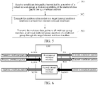
- FIG. 5 shows a flowchart of a multicast method for a multicast group of a virtual network group according to an example embodiment of the disclosure.
- the method may be performed by a first UPF.
- the method includes the following steps:
- Step 501 The first UPF receives a multicast data packet transmitted by a member of a virtual network group, a destination address of the multicast data packet being a multicast address.
- the multicast data packet is determined by using a destination IP address or a destination MAC address.
- a destination IP/MAC address in the multicast data packet is a multicast address, there may be a plurality of multicast addresses (for example, three or five) in the same virtual network group, and a plurality of multicast addresses may form a multicast address list.
- a destination address in a multicast data packet only needs to be one multicast address in a multicast address list.
- Step 502 The first UPF transmits the multicast data packet to a target internal multicast interface in at least two internal multicast interfaces.
- a PSA UPF provides at least two internal multicast interfaces.
- the at least two internal multicast interfaces include:
- a first internal multicast interface used for receiving a multicast data packet transmitted by a local multicast group member through N3/N9, and transmitting the multicast data packet to all multicast group members (which may include the transmitting member itself) of a multicast group through at least one reference point of N3/N9, N6, and N19.
- a 5G system is used as an example.
- the first internal multicast interface may be referred to as 5G VN BC internal R or another name.
- a second internal multicast interface used for transmitting, through N3/N9 to all local multicast group members of a multicast group in a PSA UPF, a multicast data packet transmitted by a non-local multicast group member through N6/N19.
- a 5G system is used as an example.
- the second internal multicast interface may be referred to as 5G VN BC internal C or another name.
- a local multicast group member includes a UE that uses a current UPF as a protocol data unit (PDU) session anchor in the multicast group.
- PDU protocol data unit
- Step 503 The first UPF transmits the multicast data packet to all multicast group members or all local multicast group members of a multicast group through the target internal multicast interface.
- a UPF calculates, according to a multicast address, a multicast group member that needs to receive the multicast data packet, transmits the multicast data packet to a target internal multicast interface in the at least two internal multicast interfaces, and transmits the multicast data packet to all members of a multicast group through the target internal multicast interface, so that one-to-multiple network communication is implemented in the virtual network group, thereby implementing a multicast function in the virtual network group.
- the at least two internal multicast interfaces of the UPF at least have the following different implementations:
- each second internal multicast interface corresponds to one multicast address, and n is a quantity of multicast addresses
- a single PSA UPF is used for describing the internal multicast interface.
- an entire transmission process of a multicast data packet may involve a plurality of PSA UPFs.
- a processing process of each PSA UPF is the same or similar.
- Multicast communication in an entire virtual network group is implemented through transmission among a plurality of PSA UPFs. Details are not described for each PSA UPF in this specification.
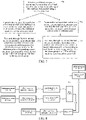
- FIG. 7 shows a flowchart of a multicast method for a multicast group of a virtual network group according to an example embodiment of the disclosure.
- the method may be performed by a first UPF, and the method includes the following steps:
- Step 701 The first UPF receives a multicast data packet transmitted by a member of a virtual network group, a destination address of the multicast data packet being a multicast address.
- member A may be any member of the virtual network group.
- Member A may be a multicast group member of a multicast group, or may not be a multicast group member of a multicast group. The same member may be connected to one multicast group or a plurality of multicast groups. In this embodiment, an example in which member A is connected to a multicast group member of a multicast group is used for description.
- the destination address of the multicast data packet is one multicast address of a plurality of multicast addresses.
- the first UPF When the multicast group member A is a local multicast group member in the first UPF, the first UPF receives the multicast data packet of member A through N3 or N9. When the multicast group member A is a non-local multicast group member in the first UPF, the first UPF receives the multicast data packet of member A through N6 or N19.
- Step 702 The first UPF transmits the multicast data packet to a first internal multicast interface when the multicast data packet is multicast data from a first reference point or a second reference point.
- the first UPF When receiving a multicast data packet transmitted by a local multicast group member through N3 or N9, the first UPF transmits the multicast data packet to the first internal multicast interface.
- Step 703 The first UPF transmits, through the first internal multicast interface, the multicast data packet from the first reference point or the second reference point or a third reference point or a fourth reference point corresponding to each multicast group member of a multicast group to all multicast group members of the multicast group.
- member A, member B, member C, and member D belong to the same multicast group.
- the first internal multicast interface transmits the multicast data packet to the multicast group member B through N3 or N9 corresponding to the multicast group member B.
- the multicast group member C is a device on a DN
- the first internal multicast interface transmits the multicast data packet to the multicast group member C through N6 corresponding to the multicast group member C.
- the first internal multicast interface transmits the multicast data packet to the multicast group member D through N19 corresponding to the multicast group member D, as shown in FIG. 8 .
- All multicast group members in this step may include the member that transmits the multicast data packet, or may not include the member that transmits the multicast data packet.
- Step 704 The first UPF transmits the multicast data packet to a second internal multicast interface when the multicast data packet is multicast data from a third reference point or a fourth reference point.
- the first UPF When receiving a multicast data packet transmitted by a non-local multicast group member through N6 or N19, the first UPF transmits the multicast data packet to the second internal multicast interface.
- Step 705 The first UPF transmits, through the second internal multicast interface, the multicast data packet from a first reference point or a second reference point corresponding to each local multicast group member in the first UPF to all local multicast group members in the first UPF.
- PSA UPF1 receives the multicast data packet from N6, places the multicast data packet into a second internal multicast interface thereof, transmits the multicast data packet to the multicast group member A through the second internal multicast interface and N9 corresponding to the multicast group member A, and transmits the multicast data packet to the multicast group member B through N9 corresponding to the multicast group member B.
- PSA UPF2 also receives the multicast data packet from N6, places the multicast data packet into a second internal multicast interface thereof, and transmits the multicast data packet to member D through the second internal multicast interface and N3 corresponding to member D. In this way, the multicast data packet transmitted by the multicast group member C is transmitted to all multicast group members.
- PSA UPF1 when the multicast group member A transmits a multicast data packet, PSA UPF1 receives the multicast data packet from N9, places the multicast data packet into a first internal multicast interface thereof, transmits the multicast data packet from N6 corresponding to the multicast group member C to the multicast group member C through the first internal multicast interface, and transmits the multicast data packet from N9 corresponding to the multicast group member B to the multicast group member B through the first internal multicast interface (PSA UPF1 may also transmit the multicast data packet from N9 to PSA UPF2 according to network configuration).
- PSA UPF2 receives the multicast data packet from N19, and places the multicast data packet into a second internal multicast interface thereof, and transmits the multicast data packet to the local multicast group member D through the second internal multicast interface and N3. In this way, the multicast data packet transmitted by the multicast group member A is transmitted to all multicast group members.
- the multicast data packet of the local multicast group member is first transmitted to the first internal multicast interface, and then is transmitted to all multicast group members of a multicast group through the first internal multicast interface (in a path other than the current UPF, a second internal multicast interface or a third internal multicast interface of another UPF may be further required to transmit the multicast data packet to all the multicast group members of the multicast group), so that multicast communication in the multicast group may be implemented.
- the multicast data packet of the non-local multicast group member is first transmitted to the second internal multicast interface, and then is transmitted to all local multicast group members connected to the UPF through the second internal multicast interface, so that multicast communication in a multicast group may be implemented, unnecessary traffic forwarding may be avoided, and network transmission resources may be saved.
- an implementation process of multicast traffic forwarding in a multicast group is as follows: For each UPF in the multicast group, at least two internal multicast interfaces in the UPF are used. Two steps are used for detecting multicast data packet forwarding between internal multicast interfaces of each UPF.
- a packet detection rule (PDR) installed in the UPF detects a multicast data packet received from a member in any multicast group (through N3, N9, N6, or N19). After the multicast data packet matches the PDR, a forwarding action rule (FAR) in the UPF is applied to forward the multicast data packet to an internal multicast interface of the UPF, that is, a destination interface specified for the internal multicast interface.
- PDR packet detection rule
- FAR forwarding action rule
- a PDR installed in the internal multicast interface of the UPF detects the multicast data packet. After the multicast data packet matches the PDR, a corresponding FAR in the internal multicast interface is applied to forward the multicast data packet to all multicast group members or all local multicast group members through N3, N6, N9, or N19.
- an N4 rule that is, a PDR and an FAR
- an example configuration of the PDR and the FAR is as follows:
- An SMF provides a first PDR and a first FAR for an N4 session of each multicast group member of the multicast group (that is, an N4 session corresponding to a PDU session of each member), so that the UPF processes a multicast data packet received from the UE.
- a first PDR and a first FAR that correspond to each local multicast group member are specified in the UPF.
- the UPF transmits the multicast data packet to the first internal multicast interface by using the first FAR, as shown in FIG. 9 .
- the first PDR includes that: a source interface is set to an access side, a target address is set to a first multicast address list to which a multicast group member belongs, and core network tunnel information is set to a tunnel header of a first reference point or a second reference point of a PDU session (including an uplink IP address and uplink GTP-U TEID information that correspond to the N3 or N9 interface), where GTP-U TEID is the abbreviation of GPRS tunnel protocol tunnel endpoint identifier.
- the first FAR includes that: a target interface is set to the first internal multicast interface.
- An SMF configures a second PDR and a second FAR that correspond to a group-level session to a UPF that has a need, so that the UPF processes a multicast data packet received through the third reference point N6.
- the group-level session is a session shared by all multicast group members in a multicast group.
- the group-level session is a session between the UPF and the SMF, that is, a group-level N4 session.
- a second PDR and a second FAR that correspond to a group-level session are specified in the UPF.
- the multicast data packet is transmitted to the second internal multicast interface by using the second FAR, as shown in FIG. 9 .
- the second PDR includes that: a source interface is set to a core side, and a target address is set to a second multicast address list, where the second multicast address list is a multicast address list corresponding to another multicast group member connected to a local multicast group member through the third reference point N6.
- the second FAR includes that: a target interface is set to the second internal multicast interface.
- An SMF configures a third PDR and a third FAR that correspond to a group-level session to a UPF that has a need, so that the UPF processes a multicast data packet received through the fourth reference point N19.
- a third PDR and a third FAR that correspond to a group-level session are specified in the UPF.
- the multicast data packet is transmitted to the third internal multicast interface by using the third FAR, as shown in FIG. 9 .
- the third PDR includes that: a source interface is set to a core side, a target address is set to a third multicast address list, and core network tunnel information is set to a tunnel header of the fourth reference point (including a receive IP address and receive GTP-U TEID information that correspond to the N19 interface), where the third multicast address list is a multicast address list corresponding to another multicast group member connected to a local multicast group member through the fourth reference point N19.
- the third FAR includes that: a target interface is set to the second internal multicast interface.
- An SMF provides a fourth PDR and a fourth FAR for an N4 session of each multicast group member of the multicast group (that is, an N4 session corresponding to a PDU session of each member), so that the UPF processes a multicast data packet received from the UE.
- a fourth PDR and a fourth FAR that correspond to each local multicast group member are specified in the UPF.
- the UPF transmits, by using the fourth FAR, the multicast data packet from the first reference point or the second reference point or the third reference point or the fourth reference point corresponding to each multicast group member of a multicast group to all multicast group members of the multicast group, as shown in FIG. 9 .
- the fourth PDR includes that: a source interface is set to the first internal multicast interface, and a target address is a first multicast address list to which a multicast group member belongs.
- the fourth FAR includes that: an external header creates tunnel information indicating the first reference point N3 or the second reference point N9 (including a downlink IP address and downlink GTP-U TEID information that correspond to the N3 or N9 interface), and a target interface is an access side; or, corresponding to a device on a DN, the fourth FAR further includes that: an external header creates information indicating the third reference point N6, and a target interface is a core side; or, corresponding to a member connected to an N19 tunnel, the fourth FAR further includes that: an external header creates tunnel information indicating the fourth reference point N19 (including an IP address and GTP-U TEID information of a peer PSA UPF that correspond to the N19 interface), and a target interface is a core side.
- An SMF configures a fifth PDR and a fifth FAR that correspond to a group-level session to a UPF that has a need in a multicast group, so that the UPF processes a multicast data packet received from the third reference point N6.
- the fifth PDR and the fifth FAR that correspond to the group-level session are specified in the UPF.
- the UPF transmits, by using the fifth FAR, the multicast data packet from the first reference point N3 or the second reference point N9 corresponding to each local multicast group member in the UPF to all local multicast group members in the UPF, as shown in FIG. 9 .
- the fifth PDR includes that: a source interface is set to the second internal multicast interface, and a target address is a second multicast address list, where the second multicast address list is a multicast address list corresponding to another multicast group member connected to a local multicast group member through the third reference point N6.
- the fifth FAR includes that: an external header creates tunnel information indicating the first reference point N3 or the second reference point N9 (including a downlink IP address and downlink GTP-U TEID information that correspond to the N3 or N9 interface), and a target interface is an access side.
- An SMF configures a sixth PDR and a sixth FAR that correspond to a group-level session to a UPF that has a need in a multicast group, so that the UPF processes a multicast data packet received from the fourth reference point N19.
- the sixth PDR and the sixth FAR that correspond to the group-level session are specified in the UPF.
- the UPF transmits, by using the sixth FAR, the multicast data packet from the first reference point N3 or the second reference point N9 corresponding to each local multicast group member in the UPF to all local multicast group members in the UPF, as shown in FIG. 9 .
- the sixth PDR includes that: a source interface is set to the second internal multicast interface, and a target address is a third multicast address list, where the third multicast address list is a multicast address list corresponding to another multicast group member connected to a local multicast group member through the fourth reference point N19.
- the sixth FAR includes that: an external header creates tunnel information indicating the first reference point N3 or the second reference point N9 (including a downlink IP address and downlink GTP-U TEID information that correspond to the N3 or N9 interface), and a target interface is an access side.
- FIG. 10 shows a flowchart of a multicast method for a multicast group of a virtual network group according to an example embodiment of the disclosure.
- the method may be performed by a first UPF, and the method includes the following steps:
- Step 1001 The first UPF receives a multicast data packet transmitted by a member of a virtual network group, a destination address of the multicast data packet being a multicast address.
- member A may be any member of the virtual network group.
- Member A may be a multicast group member of a multicast group, or may not be a multicast group member of a multicast group. The same member may be connected to one multicast group or a plurality of multicast groups. In this embodiment, an example in which member A is connected to a multicast group member of a multicast group is used for description.
- the destination address of the multicast data packet is one multicast address of a plurality of multicast addresses.
- the first UPF When the multicast group member A is a local multicast group member in the first UPF, the first UPF receives the multicast data packet of the multicast group member A through N3 or N9. When the multicast group member A is a non-local multicast group member in the first UPF, the first UPF receives the multicast data packet of the multicast group member A through N6 or N19.
- Step 1002 The first UPF transmits the multicast data packet to a first internal multicast interface when the multicast data packet is multicast data from a first reference point or a second reference point.
- the first UPF When receiving a multicast data packet transmitted by a local multicast group member through N3 or N9, the first UPF transmits the multicast data packet to the first internal multicast interface.
- Step 1003 The first UPF transmits, through the first internal multicast interface, the multicast data packet from the first reference point or the second reference point or a third reference point or a fourth reference point corresponding to each multicast group member of a multicast group to all multicast group members of the multicast group.
- the first internal multicast interface transmits the multicast data packet to the multicast group member B through N3 or N9 corresponding to the multicast group member B.
- the first internal multicast interface transmits the multicast data packet to member C through N6 corresponding to the multicast group member C.
- the first internal multicast interface transmits the multicast data packet to PSA UPF2 connected to the multicast group member D through N19 corresponding to the multicast group member D
- PSA UPF2 transmits the multicast data packet to a second internal multicast interface
- the second internal multicast interface transmits the multicast data packet from N3 to the multicast group member D, as shown in FIG. 8 .
- All multicast group members in this step may include the member that transmits the multicast data packet, or may not include the member that transmits the multicast data packet.
- Step 1004 The first UPF transmits the multicast data packet to a second internal multicast interface when the multicast data packet is multicast data from a third reference point.
- the first UPF When receiving a multicast data packet transmitted by a non-local multicast group member through N6, the first UPF transmits the multicast data packet to the second internal multicast interface.
- Step 1005 The first UPF transmits, through the second internal multicast interface, the multicast data packet from a first reference point or a second reference point corresponding to each local multicast group member of the multicast group in the first UPF to all local multicast group members in the first UPF.
- PSA UPF1 receives the multicast data packet from N6, places the multicast data packet into a second internal multicast interface thereof, transmits the multicast data packet to the multicast group member A through the second internal multicast interface and N9 corresponding to the multicast group member A, and transmits the multicast data packet to the multicast group member B through N9 corresponding to the multicast group member B.
- PSA UPF2 also receives the multicast data packet from N6, places the multicast data packet into a second internal multicast interface thereof, and transmits the multicast data packet to the multicast group member D through the second internal multicast interface and N3 corresponding to the multicast group member D. In this way, the multicast data packet transmitted by the multicast group member C is transmitted to all multicast group members.
- Step 1006 The first UPF transmits the multicast data packet to a third internal multicast interface when the multicast data packet is multicast data from a fourth reference point.
- the UPF When receiving a multicast data packet transmitted by a non-local multicast group member through N19, the UPF transmits the multicast data packet to the third internal multicast interface.
- Step 1007 The first UPF transmits, through the third internal multicast interface, the multicast data packet from a first reference point or a second reference point corresponding to each local multicast group member in the first UPF to all local multicast group members in the first UPF.
- PSA UPF1 when the multicast group member A transmits a multicast data packet, PSA UPF1 receives the multicast data packet from N9, places the multicast data packet into a first internal multicast interface thereof, transmits the multicast data packet from the N9 interface corresponding to the multicast group member B to the multicast group member B through the first internal multicast interface (or PSA UPF1 may transmit the data from the N9 interface to the multicast group member A itself according to network configuration), transmits the multicast data packet from the N6 interface to the multicast group member C of the DN, and transmits the multicast data packet from the N19 interface to PSA UPF2.
- PSA UPF2 receives the multicast data packet from N19, places the multicast data packet into a third internal multicast interface thereof, and transmits the multicast data packet to the local multicast group member D through the third internal multicast interface and the N3 interface. In this way, the multicast data packet transmitted by the multicast group member A is transmitted to all multicast group members.
- the multicast data packet of the local multicast group member is first transmitted to the first internal multicast interface, and then is transmitted to all multicast group members of a multicast group through the first internal multicast interface, so that multicast communication of the multicast group may be implemented.
- the multicast data packet of the non-local multicast group member is first transmitted to a second internal multicast interface, and then is transmitted to all local multicast group members of a multicast group in the current UPF through the second internal multicast interface, so that multicast communication in a multicast group may be implemented, unnecessary traffic forwarding may be avoided, and network transmission resources may be saved.
- the multicast data packet of the non-local multicast group member is first transmitted to the third internal multicast interface, and then is transmitted to all local multicast group members of a multicast group in the current UPF through the third internal multicast interface, so that multicast communication in a multicast group may be implemented, unnecessary traffic forwarding may be avoided, and network transmission resources may be saved.
- an implementation process of multicast traffic forwarding in a multicast group is as follows: For each UPF in the multicast group, at least two internal multicast interfaces in the UPF are used. Two steps are used for detecting multicast data packet forwarding between internal multicast interfaces of each UPF.
- a PDR installed in the UPF detects a multicast data packet received from a member in any multicast group (through N3, N9, N6, or N19).
- a FAR in the UPF is applied to forward the multicast data packet to an internal multicast interface of the UPF, that is, a destination interface specified for the internal multicast interface.
- a PDR installed in the internal multicast interface of the UPF detects the multicast data packet. After the multicast data packet matches the PDR, an FAR in the internal multicast interface is applied to forward the multicast data packet to all multicast group members or all local multicast group members of the multicast group through N3, N6, N9, or N19.
- an N4 rule that is, a PDR and an FAR
- an example configuration of the PDR and the FAR is as follows:
- An SMF provides a first PDR and a first FAR for an N4 session of each multicast group member of the multicast group (that is, an N4 session corresponding to a PDU session of each member), so that the UPF processes a multicast data packet received from the UE.
- a first PDR and a first FAR that correspond to each local multicast group member are specified in the UPF.
- the UPF transmits the multicast data packet to the first internal multicast interface by using the first FAR, as shown in FIG. 9 .
- the first PDR includes that: a source interface is set to an access side, a target address is set to a first multicast address list to which a multicast group member belongs, and core network tunnel information is set to a tunnel header of a first reference point or a second reference point of a PDU session (including an uplink IP address and uplink GTP-U TEID information that correspond to the N3 or N9 interface).
- the first FAR includes that: a target interface is set to the first internal multicast interface.
- the multicast address in the multicast data packet is a multicast address in the first multicast address list.
- An SMF configures a second PDR and a second FAR that correspond to a group-level session to a UPF that has a need, so that the UPF processes a multicast data packet received through N6.
- the group-level session is a session shared by all multicast group members in a multicast group.
- the group-level session is a session between the UPF and the SMF, that is, a group-level N4 session.
- a second PDR and a second FAR that correspond to a group-level session are specified in the UPF.
- the multicast data packet is transmitted to the second internal multicast interface by using the second FAR, as shown in FIG. 9 .
- the second PDR includes that: a source interface is set to a core side, and a target address is set to a second multicast address list, where the second multicast address list is a multicast address list corresponding to another multicast group member connected to a local multicast group member through the third reference point N6.
- the second FAR includes that: a target interface is set to the second internal multicast interface.
- An SMF configures a seventh PDR and a seventh FAR that correspond to a group-level session to a UPF that has a need, so that the UPF processes a multicast data packet received through N19.
- a seventh PDR and a seventh FAR that correspond to a group-level session are specified in the UPF.
- the multicast data packet is transmitted to the third internal multicast interface by using the seventh FAR, as shown in FIG. 11 .
- the seventh PDR includes that: a source interface is set to a core side, a target address is set to a third multicast address list, and core network tunnel information is set to a tunnel header of the fourth reference point (including an IP address and GTP-U TEID information that correspond to the N19 interface), where the third multicast address list is a multicast address list corresponding to another multicast group member connected to a local multicast group member through the fourth reference point N19.
- the seventh FAR includes that: a target interface is set to the third internal multicast interface.
- An SMF provides a fourth PDR and a fourth FAR for an N4 session of each multicast group member of the multicast group (that is, an N4 session corresponding to a PDU session of each member), so that the UPF processes a multicast data packet received from the UE.
- a fourth PDR and a fourth FAR that correspond to each local multicast group member are specified in the UPF.
- the UPF transmits, by using the fourth FAR, the multicast data packet from the first reference point or the second reference point or the third reference point or the fourth reference point corresponding to each multicast group member of a multicast group to all multicast group members of the multicast group, as shown in FIG. 9 .
- the fourth PDR includes that: a source interface is set to the first internal multicast interface, and a target address is a first multicast address list to which a multicast group member belongs.
- the fourth FAR includes that: an external header creates tunnel information indicating the first reference point N3 or the second reference point N9 (including a downlink IP address and downlink GTP-U TEID information that correspond to the N3 or N9 interface), and a target interface is an access side; or, corresponding to a device on a DN, the fourth FAR further includes that: an external header creates information indicating the third reference point N6, and a target interface is a core side; or, corresponding to a member connected to an N19 tunnel, the fourth FAR further includes that: an external header creates tunnel information indicating the fourth reference point N19 (including an IP address and GTP-U TEID information that correspond to the N19 interface), and a target interface is a core side.
- An SMF configures a fifth PDR and a fifth FAR that correspond to a group-level session to a UPF that has a need in a multicast group, so that the UPF processes a multicast data packet received from N6.
- the fifth PDR and the fifth FAR that correspond to the group-level session are specified in the UPF.
- the UPF transmits, by using the fifth FAR, the multicast data packet from the first reference point N3 or the second reference point N9 corresponding to each local multicast group member in the UPF to all local multicast group members in the UPF, as shown in FIG. 9 .
- the fifth PDR includes that: a source interface is set to the second internal multicast interface, and a target address is a second multicast address list, where the second multicast address list is a multicast address list corresponding to another multicast group member connected to a local multicast group member through the third reference point N6.
- the fifth FAR includes that: an external header creates tunnel information indicating the first reference point N3 or the second reference point N9 (including a downlink IP address and downlink GTP-U TEID information that correspond to the N3 or N9 interface), and a target interface is an access side.
- An SMF configures an eighth PDR and an eighth FAR that correspond to a group-level session to a UPF that has a need in a multicast group, so that the UPF processes a multicast data packet received from N19.
- the eighth PDR and the eighth FAR that correspond to the group-level session are specified in the UPF.
- the UPF transmits, by using the eighth FAR, the multicast data packet from the first reference point N3 or the second reference point N9 corresponding to each local multicast group member in the UPF to all local multicast group members in the UPF, as shown in FIG. 11 .
- the eighth PDR includes that: a source interface is set to the third internal multicast interface, and a target address is a third multicast address list, where the third multicast address list is a multicast address list corresponding to another multicast group member connected to a local multicast group member through the fourth reference point N19.
- the eighth FAR includes that: an external header creates tunnel information indicating the first reference point N3 or the second reference point N9 (including a downlink IP address and downlink GTP-U TEID information that correspond to the N3 or N9 interface), and a target interface is an access side.
- the first multicast address list is all multicast addresses of multicast groups to which a multicast group member belongs.
- the second multicast address list is a set of multicast address lists of multicast groups to which all local multicast group members in the first UPF belong.
- the third multicast address list is an intersection set of a multicast address list of multicast groups to which local multicast group members in the first UPF belong and a multicast address list of multicast groups to which local multicast group members of a second UPF belong, and the second UPF is connected to the first UPF through the fourth reference point.
- the multicast address lists (the first multicast address list, the second multicast address list, and the third multicast address list) in the PDR and the FAR include a plurality of multicast addresses, for example, three multicast addresses or five multicast addresses.
- At least one of the first internal multicast interface, the second internal multicast interface, and the third internal multicast interface may be implemented as m internal multicast interfaces, and each internal multicast interface corresponds to one multicast address; m being a positive integer, and i being an integer not greater than m.
- an i th first internal multicast interface corresponds to an i th multicast address in the first multicast address list, and it is assumed that the multicast address in the multicast data packet is the i th multicast address.
- the first PDR includes that: a source interface is set to an access side, a target address is set to the i th multicast address in the first multicast address list, and core network tunnel information is set to a tunnel header of a first reference point or a second reference point of a PDU session; and the first FAR includes that: a target interface is set to the i th first internal multicast interface.
- the fourth PDR includes that: a source interface is set to the i th first internal multicast interface, and a target address is the i th multicast address in the first multicast address list; and the fourth FAR includes that: an external header creates tunnel information indicating the first reference point or the second reference point, and a target interface is an access side; or, the fourth FAR further includes that: an external header creates tunnel information indicating a third reference point, and a target interface is a core side; or, the fourth FAR further includes that: an external header creates tunnel information indicating a fourth reference point, and a target interface is a core side.
- an i th second internal multicast interface corresponds to an i th multicast address in the second multicast address list, and it is assumed that the multicast address in the multicast data packet is the i th multicast address.
- the second PDR includes that: a source interface is set to a core side, and a target address is set to the i th multicast address; and the second FAR includes that: a target interface is set to the i th second internal multicast interface.
- the fifth PDR includes that: a source interface is set to the i th second internal multicast interface, and a target address is the i th multicast address in the second multicast address list; and the fifth FAR includes that: an external header creates tunnel information indicating the first reference point or the second reference point, and a target interface is an access side.
- the third PDR includes that: a source interface is set to a core side, a target address is set to an i th multicast address in the third multicast address list, and core network tunnel information is set to a tunnel header of the fourth reference point; and the third FAR includes that: a target interface is set to the i th second internal multicast interface, m being a positive integer, and i being an integer not greater than m.
- the sixth PDR includes that: a source interface is set to the i th second internal multicast interface, and a target address is the i th multicast address in the third multicast address list; and the fifth FAR includes that: an external header creates tunnel information indicating the first reference point or the second reference point, and a target interface is an access side.
- an i th third internal multicast interface corresponds to an i th multicast address in the third multicast address list, and it is assumed that the multicast address in the multicast data packet is the i th multicast address.
- the seventh PDR includes that: a source interface is set to a core side, a target address is set to the i th multicast address in the third multicast address list, and core network tunnel information is set to a tunnel header of the fourth reference point; and the seventh FAR includes that: a target interface is set to the i th third internal multicast interface.
- the eighth PDR includes that: a source interface is set to the i th third internal multicast interface, and a target address is the i th multicast address; and the eighth FAR includes that: an external header creates tunnel information indicating the first reference point or the second reference point, and a target interface is an access side.
- the at least two internal multicast interfaces include the first internal multicast interface and m second internal multicast interfaces.
- Each second internal multicast interface corresponds to one multicast address, and m is a quantity of multicast addresses.
- the first UPF transmits, when the multicast data packet is multicast data from the first reference point or the second reference point, the multicast data packet to the first internal multicast interface, and transmits, through the first internal multicast interface, the multicast data packet from the first reference point or the second reference point or the third reference point or the fourth reference point corresponding to each multicast group member of the multicast group to all the multicast group members of the multicast group.
- the first UPF transmits, when the multicast data packet is multicast data from the third reference point or the fourth reference point and a multicast address of the multicast data packet is an i th multicast address, the multicast data packet to the second internal multicast interface corresponding to the i th multicast address, and transmits the multicast data packet from the first reference point or the second reference point corresponding to each local multicast group member in the first UPF to all local multicast group members in the first UPF through the second internal multicast interface corresponding to the i th multicast address.
- VID For a first implementation of a VID:
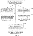
- FIG. 12 shows a flowchart of a multicast method for a VID of a virtual network group according to an example embodiment of the disclosure.
- the method may be performed by a first UPF, and the method includes the following steps:
- Step 1201 The first UPF receives a multicast data packet transmitted by a member of a virtual network group, a destination address of the multicast data packet being a VID and a broadcast address.
- member transmitting the multicast data packet is member A, and member A may be any member of the virtual network group.
- the same member may be connected to one or more VIDs.
- a destination address of each multicast data packet is one of the plurality of broadcast addresses.
- the first UPF When member A is a local VID member in the first UPF, the first UPF receives the multicast data packet of member A through N3 or N9. When member A is a non-local VID member in the first UPF, the first UPF receives the multicast data packet of member A through N6 or N19.
- Step 1202 The first UPF transmits the multicast data packet to a first internal multicast interface when the multicast data packet is multicast data from a first reference point or a second reference point.
- the UPF When receiving a multicast data packet transmitted by a local VID member through N3 or N9, the UPF transmits the multicast data packet to the first internal multicast interface.
- Step 1203 The first UPF transmits, through the first internal multicast interface, the multicast data packet from the first reference point or the second reference point or a third reference point or a fourth reference point corresponding to each VID member of a VID to all VID members of the VID.
- member A, member B, member C, and member D belong to the same VID.
- VID member B is a member connected to the same PSA UPF as the VID member A
- the first internal multicast interface transmits the multicast data packet to VID member B through N3 or N9 corresponding to the VID member B.
- VID member C is a device on a DN
- the first internal multicast interface transmits the multicast data packet to VID member C through N6 corresponding to the VID member C.
- VID member D is a member connected to a different PSA UPF from the VID member A
- the first internal multicast interface transmits the multicast data packet to VID member D through N19 corresponding to the VID member D, as shown in FIG. 8 .
- All VID members" in this step may include the member that transmits the multicast data packet, or may not include the member that transmits the multicast data packet.
- Step 1204 The first UPF transmits the multicast data packet to a second internal multicast interface when the multicast data packet is multicast data from the third reference point or the fourth reference point.
- the first UPF When receiving a multicast data packet transmitted by a non-local multicast group member through N6 or N19, the first UPF transmits the multicast data packet to the second internal multicast interface.
- Step 1205 transmit, through the second internal multicast interface, the multicast data packet from the first reference point or the second reference point corresponding to each local VID member in the first UPF to all local VID members in the first UPF.
- PSA UPF1 receives the multicast data packet from N6, places the multicast data packet into a second internal multicast interface thereof, transmits the multicast data packet to VID member A through the second internal multicast interface and N9 corresponding to the VID member A, and transmits the multicast data packet to VID member B through N9 corresponding to the VID member B.
- PSA UPF2 also receives the multicast data packet from N6, places the multicast data packet into a second internal multicast interface thereof, and transmits the multicast data packet to member D through the second internal multicast interface and N3 corresponding to member D. In this way, the multicast data packet transmitted by VID member C is transmitted to all VID members.
- PSA UPF1 when VID member A transmits a multicast data packet, PSA UPF1 receives the multicast data packet from N9, places the multicast data packet into a first internal multicast interface thereof, transmits the multicast data packet from N6 corresponding to VID member C to VID member C through the first internal multicast interface, and transmits the multicast data packet from N9 corresponding to VID member B to VID member B through the first internal multicast interface (PSA UPF1 may also transmit the multicast data packet from N9 to PSA UPF2 according to network configuration).
- PSA UPF2 receives the multicast data packet from N19, and places the multicast data packet into a second internal multicast interface thereof, and transmits the multicast data packet to the local VID member D through the second internal multicast interface and N3. In this way, the multicast data packet transmitted by VID member A is transmitted to all VID members.
- the multicast data packet of the local VID member is first transmitted to the first internal multicast interface, and then is transmitted to all VID members of a VID through the first internal multicast interface (in a path other than the current UPF, a second internal multicast interface or a third internal multicast interface of another UPF may be further required to transmit the multicast data packet to all the multicast group members of the multicast group), so that multicast communication in the VID may be implemented.
- the multicast data packet of the non-local VID member is first transmitted to the second internal multicast interface, and then is transmitted to all local VID members connected to the UPF through the second internal multicast interface, so that multicast communication in a VID may be implemented, unnecessary traffic forwarding may be avoided, and network transmission resources may be saved.
- an implementation process of multicast traffic forwarding in a VID is as follows: For each UPF in the VID, at least two internal multicast interfaces in the UPF are used. Two steps are used for detecting multicast data packet forwarding between internal multicast interfaces of each UPF.
- a PDR installed in the UPF detects a multicast data packet received from a member in any VID (through N3, N9, N6, or N19). After the multicast data packet matches the PDR, an FAR in the UPF is applied to forward the multicast data packet to an internal multicast interface of the UPF, that is, a destination interface specified for the internal multicast interface.
- a PDR installed in the internal multicast interface of the UPF detects the multicast data packet. After the multicast data packet matches the PDR, a corresponding FAR in the internal multicast interface is applied to forward the multicast data packet to all members in the VID through N3, N6, N9, or N19.
- an N4 rule that is, a PDR and an FAR
- an example configuration of the PDR and the FAR is as follows:
- An SMF provides a first PDR and a first FAR for an N4 session of each VID member in the VID (that is, an N4 session corresponding to a PDU session of each member), so that the UPF processes a multicast data packet received from the UE.
- a first PDR and a first FAR that correspond to each local VID member are specified in the UPF.
- the UPF transmits the multicast data packet to the first internal multicast interface by using the first FAR, as shown in FIG. 9 .
- the first PDR includes that: a source interface is set to an access side, a target address is set to a first VID list to which a VID member belongs and a broadcast address, and core network tunnel information is set to a tunnel header of the first reference point N3 or the second reference point N9 of a PDU session (including an uplink IP address and uplink GTP-U TEID information that correspond to the N3 or N9 interface).
- the first FAR includes that: a target interface is set to the first internal multicast interface.
- the multicast address in the multicast data packet is a VID in the first VID list to which the VID member belongs, and the broadcast address.
- An SMF configures a second PDR and a second FAR that correspond to a group-level session to a UPF that has a need, so that the UPF processes a multicast data packet received through N6.
- the group-level session is a session shared by all VID members in a VID.
- the group-level session is a session between the UPF and the SMF, that is, a group-level N4 session.
- a second PDR and a second FAR that correspond to a group-level session are specified in the UPF.
- the multicast data packet is transmitted to the second internal multicast interface by using the second FAR, as shown in FIG. 9 .
- the second PDR includes that: a source interface is set to a core side, a target address is set to a second VID list and a broadcast address, where the second VID list is a VID list corresponding to another VID member connected to a local VID member through the third reference point N6.
- the second FAR includes that: a target interface is set to the second internal multicast interface.
- the second VID list is a VID list of all VIDs in the virtual network group; or the second VID list is a set of VID lists to which all local VID members in the first UPF belong.
- An SMF configures a third PDR and a third FAR that correspond to a group-level session to a UPF that has a need, so that the UPF processes a multicast data packet received through N19.
- a third PDR and a third FAR that correspond to a group-level session are specified in the UPF.
- the multicast data packet is transmitted to the third internal multicast interface by using the third FAR, as shown in FIG. 9 .
- the third PDR includes that: a source interface is set to a core side, a target address is set to a third VID list and a broadcast address, and core network tunnel information is set to a tunnel header of the fourth reference point (including a receive IP address and receive GTP-U TEID information that correspond to the N19 interface), where the third VID list is a VID list corresponding to another VID member connected to a local multicast group member through the fourth reference point N19.
- the third FAR includes that: a target interface is set to the second internal multicast interface.
- An SMF provides a fourth PDR and a fourth FAR for an N4 session of each VID member of the VID (that is, an N4 session corresponding to a PDU session of each member), so that the UPF processes a multicast data packet received from the UE.
- a fourth PDR and a fourth FAR that correspond to a local VID member are specified in the UPF.
- the UPF transmits, by using the fourth FAR, the multicast data packet from the first reference point or the second reference point or the third reference point or the fourth reference point corresponding to each VID member of a VID to all VID members of the VID, as shown in FIG. 9 .
- the fourth PDR includes that: a source interface is set to the first internal multicast interface, and a target address is a first VID list to which a VID member belongs and a broadcast address.
- the fourth FAR includes that: an external header creates tunnel information indicating the first reference point N3 or the second reference point N9 (including a downlink IP address and downlink GTP-U TEID information that correspond to the N3 or N9 interface), and a target interface is an access side; or, corresponding to a device on a DN, the fourth FAR further includes that: an external header creates information indicating the third reference point N6, and a target interface is a core side; or, corresponding to a member connected to an N19 tunnel, the fourth FAR further includes that: an external header creates tunnel information indicating the fourth reference point N19 (including an IP address and GTP-U TEID information of a peer PSA UPF that correspond to the N19 interface), and a target interface is a core side.
- An SMF configures a fifth PDR and a fifth FAR that correspond to a group-level session to a UPF that has a need in a VID, so that the UPF processes a multicast data packet received from N6 or N19.
- the fifth PDR and the fifth FAR that correspond to the group-level session are specified in the UPF.
- the UPF transmits, by using the fifth FAR, the multicast data packet from the first reference point N3 or the second reference point N9 corresponding to each local multicast group member in the UPF to all local VID members in the UPF, as shown in FIG. 9 .
- the fifth PDR includes that: a source interface is set to the second internal multicast interface, and a target address is a second VID list of the VID and a broadcast address.
- the fifth FAR includes that: an external header creates tunnel information indicating the first reference point N3 or the second reference point N9 (including a downlink IP address and downlink GTP-U TEID information that correspond to the N3 or N9 interface), and a target interface is an access side.
- An SMF configures a sixth PDR and a sixth FAR that correspond to a group-level session to a UPF that has a need in a VID, so that the UPF processes a multicast data packet received from N19.
- the sixth PDR and the sixth FAR that correspond to the group-level session are specified in the UPF.
- the UPF transmits, by using the sixth FAR, the multicast data packet from the first reference point N3 or the second reference point N9 corresponding to each local VID member in the UPF to all local VID members in the UPF, as shown in FIG. 9 .
- the sixth PDR includes that: a source interface is set to the second internal multicast interface, and a target address is a third VID list and a broadcast address, where the third VID list is a multicast address list corresponding to another VID member connected to a local VID member through the fourth reference point N19.
- the sixth FAR includes that: an external header creates tunnel information indicating the first reference point N3 or the second reference point N9 (including a downlink IP address and downlink GTP-U TEID information that correspond to the N3 or N9 interface), and a target interface is an access side.
- VID For a second implementation of a VID:
- FIG. 13 shows a flowchart of a multicast method for a VID of a virtual network group according to an example embodiment of the disclosure.
- the method may be performed by a first UPF, and the method includes the following steps:
- Step 1301 The first UPF receives a multicast data packet transmitted by a member of a virtual network group, a destination address of the multicast data packet being a VID and a broadcast address.
- member A may be any member of the virtual network group.
- Member A may be a VID member of the VID, or may not be a VID member of the VID. The same member may be connected to one or more VIDs. In this embodiment, an example in which member A is connected to a VID member of a VID is used for description.
- VID member A When VID member A is connected to a plurality of VIDs, and each VID corresponds to one broadcast address, a destination address of a multicast data packet is one of a plurality of broadcast addresses.
- VID member A When VID member A is a local VID member in the first UPF, the UPF receives the multicast data packet of VID member A through N3 or N9. When VID member A is a non-local multicast group member in the first UPF, the first UPF receives the multicast data packet of VID member A through N6 or N19.
- Step 1302 The first UPF transmits the multicast data packet to a first internal multicast interface when that the multicast data packet is multicast data from a first reference point or a second reference point.
- the first UPF When receiving a multicast data packet transmitted by a local multicast group member through N3 or N9, the first UPF transmits the multicast data packet to the first internal multicast interface.
- Step 1303 The first UPF transmits, through the first internal multicast interface, the multicast data packet from the first reference point or the second reference point or a third reference point or a fourth reference point corresponding to each VID member of a VID to all VID members of the VID.
- the first internal multicast interface transmits the multicast data packet to VID member B through N3 or N9 corresponding to VID member B.
- VID member C is a device on a DN
- the first internal multicast interface transmits the multicast data packet to VID member C through N6 corresponding to VID member C.
- the first internal multicast interface transmits the multicast data packet to PSA UPF2 connected to VID member D through N19 corresponding to VID member D
- PSA UPF2 transmits the multicast data packet to a third internal multicast interface
- the third internal multicast interface transmits the multicast data packet from N3 to VID member D, as shown in FIG. 8 .
- All VID members" in this step may include the member that transmits the multicast data packet, or may not include the member that transmits the multicast data packet.
- Step 1304 The first UPF transmits the multicast data packet to a second internal multicast interface when the multicast data packet is multicast data from the third reference point.
- the first UPF When receiving a multicast data packet transmitted by a non-local multicast group member through N6, the first UPF transmits the multicast data packet to the second internal multicast interface.
- Step 1305 The first UPF transmits, through the second internal multicast interface, the multicast data packet from a first reference point or a second reference point corresponding to each local VID member of the VID in the first UPF to all local VID members in the first UPF.
- PSA UPF1 receives the multicast data packet from N6, places the multicast data packet into a second internal multicast interface thereof, transmits the multicast data packet to VID member A through the second internal multicast interface and N9 corresponding to the VID member A, and transmits the multicast data packet to VID member B through N9 corresponding to the VID member B.
- PSA UPF2 also receives the multicast data packet from N6, places the multicast data packet into a second internal multicast interface thereof, and transmits the multicast data packet to VID member D through the second internal multicast interface thereof and N3 corresponding to VID member D. In this way, the multicast data packet transmitted by VID member C is transmitted to all VID members.
- Step 1306 The first UPF transmits the multicast data packet to a third internal multicast interface when the multicast data packet is multicast data from the fourth reference point.
- the first UPF When receiving a multicast data packet transmitted by a non-local VID member through N19, the first UPF transmits the multicast data packet to the third internal multicast interface.
- Step 1307 The first UPF transmits, through the third internal multicast interface, the multicast data packet from the first reference point or the second reference point corresponding to each local VID member in the UPF to all local VID members in the first UPF.
- PSA UPF1 when VID member A transmits a multicast data packet, PSA UPF1 receives the multicast data packet from N9, places the multicast data packet into a first internal multicast interface thereof, transmits the multicast data packet from the N9 interface corresponding to VID member B to VID member B through the first internal multicast interface (or PSA UPF1 may transmit the data from the N9 interface to VID member A itself according to network configuration), transmits the multicast data packet from the N6 interface to VID member C of the DN, and transmits the multicast data packet from the N19 interface to PSA UPF2.
- PSA UPF2 receives the multicast data packet from N19, places the multicast data packet into a third internal multicast interface thereof, and transmits the multicast data packet to the local VID member D through the third internal multicast interface and the N3 interface. In this way, the multicast data packet transmitted by VID member A is transmitted to all VID members.
- the multicast data packet of the local VID member is first transmitted to the first internal multicast interface, and then is transmitted to all VID members of a VID through the first internal multicast interface, so that multicast communication in the VID may be implemented.
- the multicast data packet of the non-local VID member is first transmitted to the second internal multicast interface, and then is transmitted to all local VID members of a VID in the current UPF through the second internal multicast interface, so that multicast communication in a VID may be implemented, unnecessary traffic forwarding may be avoided, and network transmission resources may be saved.
- the multicast data packet of the non-local VID member is first transmitted to the third internal multicast interface, and then is transmitted to all local VID members of a VID in the current UPF through the third internal multicast interface, so that multicast communication in a VID may be implemented, unnecessary traffic forwarding may be avoided, and network transmission resources may be saved.
- an implementation process of multicast traffic forwarding in a VID is as follows: For each UPF in the VID, at least two internal multicast interfaces in the UPF are used. Two steps are used for detecting multicast data packet forwarding between internal multicast interfaces of each UPF.
- a PDR installed in the UPF detects a multicast data packet received from a member in any VID (through N3, N9, N6, or N19).
- a FAR in the UPF is applied to forward the multicast data packet to an internal multicast interface of the UPF, that is, a destination interface specified for the internal multicast interface.
- a PDR installed in the internal multicast interface of the UPF detects the multicast data packet. After the multicast data packet matches the PDR, an FAR in the internal multicast interface is applied to forward the multicast data packet to a VID member in the VID through N3, N6, N9, or N19.
- an N4 rule that is, a PDR and an FAR
- an example configuration of the PDR and the FAR is as follows:
- An SMF provides a first PDR and a first FAR for an N4 session of each VID member in the VID (that is, an N4 session corresponding to a PDU session of each member), so that the UPF processes a multicast data packet received from the UE.
- a first PDR and a first FAR that correspond to each local VID member are specified in the UPF.
- the UPF transmits the multicast data packet to the first internal multicast interface by using the first FAR, as shown in FIG. 9 .
- the first PDR includes that: a source interface is set to an access side, a target address is set to a first VID list to which a VID member belongs and a broadcast address, and core network tunnel information is set to a tunnel header of a first reference point or a second reference point of a PDU session (including an uplink IP address and uplink GTP-U TEID information that correspond to the N3 or N9 interface).
- the first FAR includes that: a target interface is set to the first internal multicast interface.
- a multicast address in the multicast data packet is a VID in a VID list to which the VID belongs and a broadcast address in broadcast addresses.
- An SMF configures a second PDR and a second FAR that correspond to a group-level session to a UPF that has a need, so that the UPF processes a multicast data packet received through N6.
- the group-level session is a session shared by all VID members in a VID.
- the group-level session is a session between the UPF and the SMF, that is, a group-level N4 session.
- a second PDR and a second FAR that correspond to a group-level session are specified in the UPF.
- the multicast data packet is transmitted to the second internal multicast interface by using the second FAR, as shown in FIG. 9 .
- the second PDR includes that: a source interface is set to a core side, and a target address is set to a second VID list of the VID and a broadcast address.
- the second FAR includes that: a target interface is set to the second internal multicast interface.
- the second multicast address list is a VID list of all VIDs in the virtual network group and a broadcast address; or the second multicast address list is a VID list to which all local VID members in the first UPF belong and a set of broadcast addresses.
- An SMF configures a seventh PDR and a seventh FAR that correspond to a group-level session to a UPF that has a need, so that the UPF processes a multicast data packet received through N19.
- a seventh PDR and a seventh FAR that correspond to a group-level session are specified in the UPF.
- the multicast data packet is transmitted to the third internal multicast interface by using the seventh FAR, as shown in FIG. 11 .
- the third PDR includes that: a source interface is set to a core side, a target address is set to a third VID list and a broadcast address, and core network tunnel information is set to a tunnel header of the fourth reference point (including an IP address and GTP-U TEID information that correspond to the N19 interface).
- the third FAR includes that: a target interface is set to the third internal multicast interface.
- An SMF provides a fourth PDR and a fourth FAR for an N4 session of each VID member of the VID (that is, an N4 session corresponding to a PDU session of each member), so that the UPF processes a multicast data packet received from the UE.
- a fourth PDR and a fourth FAR that correspond to a local VID member are specified in the UPF.
- the UPF transmits, by using the fourth FAR, the multicast data packet from the first reference point or the second reference point or the third reference point or the fourth reference point corresponding to each VID member of a VID to all VID members of the VID, as shown in FIG. 11 .
- the fourth PDR includes that: a source interface is set to the first internal multicast interface, and a target address is a first VID list to which a VID member belongs and a broadcast address.
- the fourth FAR includes that: an external header creates tunnel information indicating the first reference point N3 or the second reference point N9 (including a downlink IP address and downlink GTP-U TEID information that correspond to the N3 or N9 interface), and a target interface is an access side; or, corresponding to a device on a DN, the fourth FAR further includes that: an external header creates information indicating the third reference point N6, and a target interface is a core side; or, corresponding to a member connected to an N19 tunnel, the fourth FAR further includes that: an external header creates tunnel information indicating the fourth reference point N19 (including an IP address and GTP-U TEID information that correspond to the N19 interface), and a target interface is a core side.
- An SMF configures a fifth PDR and a fifth FAR that correspond to a group-level session to a UPF that has a need in a VID, so that the UPF processes a multicast data packet received from N6.
- the fifth PDR and the fifth FAR that correspond to the group-level session are specified in the UPF.
- the UPF transmits, by using the fifth FAR, the multicast data packet from the first reference point N3 or the second reference point N9 corresponding to each local multicast group member in the UPF to all local VID members in the UPF, as shown in FIG. 11 .
- the fifth PDR includes that: a source interface is set to the second internal multicast interface, and a target address is a second VID list of the VID and a broadcast address.
- the fifth FAR includes that: an external header creates tunnel information indicating the first reference point N3 or the second reference point N9 (including a downlink IP address and downlink GTP-U TEID information that correspond to the N3 or N9 interface), and a target interface is an access side.
- An SMF configures an eighth PDR and an eighth FAR that correspond to a group-level session to a UPF that has a need in a VID, so that the UPF processes a multicast data packet received from N19.
- the eighth PDR and the eighth FAR that correspond to the group-level session are specified in the UPF.
- the UPF transmits, by using the eighth FAR, the multicast data packet from the first reference point N3 or the second reference point N9 corresponding to each local VID member in the UPF to all local VID members in the UPF, as shown in FIG. 9 .
- the eighth PDR includes that: a source interface is set to the third internal multicast interface, and a target address is a third VID list, where the third VID list is a VID list corresponding to another VID member connected to a local VID member through the fourth reference point N19.
- the eighth FAR includes that: an external header creates tunnel information indicating the first reference point N3 or the second reference point N9 (including a downlink IP address and downlink GTP-U TEID information that correspond to the N3 or N9 interface), and a target interface is an access side.
- the second VID list is a VID list of all VIDs in the virtual network group; or the second VID list is a set of VID lists to which all local VID members in the first UPF belong.
- the third VID list is a VID list of all VIDs in the virtual network group; or the third VID list is an intersection set of a VID list to which local VID members in the first UPF belong and a VID list to which local VID members of the second UPF belong, and the second UPF is connected to the first UPF through the fourth reference point.
- the VID lists and the broadcast addresses (the first VID list and the broadcast address, the second VID list and the broadcast address, and the third VID list and the broadcast address) in the PDR and the FAR include broadcast addresses of a plurality of VIDs, for example, three broadcast addresses or five broadcast addresses.
- At least one of the first internal multicast interface, the second internal multicast interface, and the third internal multicast interface may be implemented as m internal multicast interfaces, and each internal multicast interface corresponds to a broadcast address of one VID; m being a positive integer, and i being an integer not greater than m.
- an i th first internal multicast interface corresponds to an i th VID, and it is assumed that the multicast address in the multicast data packet is the i th VID in the first VID list and the broadcast address.
- the first PDR includes that: a source interface is set to an access side, a target address is set to the i th VID in the first VID list and the broadcast address, and core network tunnel information is set to a tunnel header of a first reference point or a second reference point of a PDU session; and the first FAR includes that: a target interface is set to the i th first internal multicast interface.
- the fourth PDR includes that: a source interface is set to the i th first internal multicast interface, and a target address is the i th VID in the first VID list and the broadcast address; and the fourth FAR includes that: an external header creates tunnel information indicating the first reference point or the second reference point, and a target interface is an access side; or, the fourth FAR further includes that: an external header creates tunnel information indicating a third reference point, and a target interface is a core side; or, the fourth FAR further includes that: an external header creates tunnel information indicating a fourth reference point, and a target interface is a core side.
- an i th second internal multicast interface corresponds to an i th VID in the second VID list, and it is assumed that the multicast address in the multicast data packet is the i th VID in the second VID list and the broadcast address.
- the second PDR includes that: a source interface is set to a core side, and a target address is set to the i th VID in the second VID list and the broadcast address; and the second FAR includes that: a target interface is set to the i th second internal multicast interface.
- the fifth PDR includes that: a source interface is set to the i th second internal multicast interface, and a target address is the i th VID in the second VID list and the broadcast address; and the fifth FAR includes that: an external header creates tunnel information indicating the first reference point or the second reference point, and a target interface is an access side.
- the third PDR includes that: a source interface is set to a core side, a target address is set to an i th VID in the third VID list and the broadcast address, and core network tunnel information is set to a tunnel header of a fourth reference point; and the third FAR includes that: a target interface is set to the i th second internal multicast interface, m being a positive integer, and i being an integer not greater than m.
- the sixth PDR includes that: a source interface is set to the i th second internal multicast interface, and a target address is the i th VID in the third VID list and the broadcast address; and the sixth FAR includes that: an external header creates tunnel information indicating the first reference point or the second reference point, and a target interface is an access side.
- an i th third internal multicast interface corresponds to the i th VID in the second VID list, and it is assumed that the multicast address in the multicast data packet is the i th VID in the third VID list and .
- the seventh PDR includes that: a source interface is set to a core side, a target address is set to the i th VID in the third VID list and the broadcast address, and core network tunnel information is set to a tunnel header of a fourth reference point; and the seventh FAR includes that: a target interface is set to the i th third internal multicast interface.
- the eighth PDR includes that: a source interface is set to the i th third internal multicast interface, and a target address is the i th VID in the third VID list and the broadcast address; and the eighth FAR includes that: an external header creates tunnel information indicating the first reference point or the second reference point, and a target interface is an access side.
- the at least two internal multicast interfaces include a first internal multicast interface and m second internal multicast interfaces.
- Each second internal multicast interface corresponds to one VID, and m is a quantity of broadcast addresses.
- the UPF transmits, when the multicast data packet is multicast data from the first reference point or the second reference point, the multicast data packet to the first internal multicast interface, and transmits, through the first internal multicast interface, the multicast data packet from the first reference point or the second reference point or a third reference point or a fourth reference point corresponding to each VID member of a VID to all VID members of the VID.
- the UPF transmits, when the multicast data packet is multicast data from the third reference point or the fourth reference point and the broadcast address of the multicast data packet is an i th broadcast address, the multicast data packet to a second internal multicast interface corresponding to the i th VID, and transmits the multicast data packet from the first reference point or the second reference point corresponding to each local VID member of the VID in the UPF to all local VID members in the UPF through the second internal multicast interface corresponding to the i th VID.
- FIG. 14 shows a flowchart of a multicast method for a multicast group of a virtual network group according to an example embodiment of the disclosure.
- the method may be performed by an SMF, and the method includes the following steps:
- Step 1402 The SMF generates at least two groups of multicast rules corresponding to at least two internal multicast interfaces.
- Step 1404 Determine a multicast rule required on each UPF corresponding to the multicast group from the at least two groups of multicast rules, the multicast group being a conventional multicast group in the virtual network group, or the multicast group being a group identified by using a VID.
- Step 1406 The SMF configures the required multicast rule for each UPF.
- the at least two internal multicast interfaces have a plurality of implementations.
- the at least two groups of multicast rules include a first group of multicast rules that is of each multicast group member and that corresponds to the first internal multicast interface.
- Steps 1402, 1404, and 1406 may be implemented as follows, as shown in FIG. 15 :
- Step 1402a The SMF generates a first group of multicast rules that is of each multicast group member and that corresponds to the first internal multicast interface.
- Step 1404a Determine a UPF to which each multicast group member belongs, as a UPF requiring the first group of multicast rules.
- Step 1406a Configure, in a process of establishing a PDU session by each multicast group member, the first group of multicast rules for the UPF to which each multicast group member belongs.
- the first group of multicast rules includes the first PDR and the first FAR, and the fourth PDR and the fourth FAR, as mentioned in the foregoing embodiment.
- the at least two internal multicast interfaces include a second internal multicast interface
- the at least two multicast rules include a group-level second group of multicast rules that is of each multicast group and that corresponds to the second internal multicast interface, and the second group of multicast rules is used for forwarding a multicast data packet from the third reference point N6.
- Steps 1402, 1404, and 1406 may be implemented as the following steps, as shown in FIG. 16 :
- Step 1402b The SMF generates a group-level second group of multicast rules that is of each multicast group and that corresponds to the second internal multicast interface.
- the second group of multicast rules is used for forwarding the multicast data packet from the third reference point.
- Step 1404b Determine, for a first UPF in each UPF corresponding to the multicast group according to a combination set of multicast address lists of multicast groups to which local multicast group members in the first UPF belong, all group-level second groups of multicast rules corresponding to the combination set as multicast rules required in the first UPF.
- the SMF calculates the combination set of the multicast address lists of the multicast groups to which the local multicast group members in the first UPF belong.
- the SMF determines all the group-level second groups of multicast rules corresponding to the combination set of the multicast address lists as the multicast rules required in the first UPF.
- Step 1406b Configure, for the first UPF when the combination set of the multicast address lists changes, all the group-level second groups of multicast rules corresponding to the combination set.
- the SMF configures, for the first UPF when the combination set changes (e.g., a UE is added or deleted), all the group-level second groups of multicast rules corresponding to the combination set of the multicast address lists.
- the combination set changes e.g., a UE is added or deleted
- the second group of multicast rules includes a second PDR and a second FAR, and a fifth PDR and a fifth FAR.
- N6 GTP-U tunnel is recommended for sharing between the plurality of UPFs.
- the at least two internal multicast interfaces include a second internal multicast interface
- the at least two multicast rules include a group-level third group of multicast rules that is of each multicast group and that corresponds to the second internal multicast interface, and the third group of multicast rules is used for forwarding a multicast data packet from the fourth reference point N19.
- Steps 1402, 1404, and 1406 may be implemented as the following steps, as shown in FIG. 17 :
- Step 1402c The SMF generates a group-level third group of multicast rules that is of each multicast group and that corresponds to the second internal multicast interface.
- the third group of multicast rules is used for forwarding the multicast data packet from the fourth reference point N19.
- Step 1404c1 Determine, for a first UPF in each UPF corresponding to the multicast group, an intersection set of a multicast address list corresponding to a local multicast group member in the first UPF and a multicast address list corresponding to a local multicast group member in a second UPF.
- Step 1404c2 Determine all group-level third groups of multicast rules corresponding to the intersection set as multicast rules required in the first UPF and the second UPF, the second UPF being a UPF in each UPF corresponding to the multicast group except the first UPF.
- Step 1406c The SMF separately configures, for the first UPF and the second UPF when the intersection set changes, all the group-level third groups of multicast rules corresponding to the intersection set.
- the SMF separately configures, for the first UPF and the second UPF when the intersection set changes (e.g., a UE is added or deleted), all the group-level third groups of multicast rules corresponding to the intersection set.
- the third group of multicast rules includes a third PDR and a third FAR, and a sixth PDR and a sixth FAR.
- the at least two internal multicast interfaces include a third internal multicast interface
- the at least two multicast rules include a group-level fourth group of multicast rules that is of each multicast group and that corresponds to the third internal multicast interface, and the fourth group of multicast rules is used for forwarding a multicast data packet from the fourth reference point N19.
- Steps 1402, 1404, and 1406 may be implemented as the following steps, as shown in FIG. 18 :
- Step 1402c The SMF generates a group-level fourth group of multicast rules that is of each multicast group and that corresponds to the third internal multicast interface.
- the fourth group of multicast rules is used for forwarding the multicast data packet from the fourth reference point N19.
- Step 1404c1 Determine, for a first UPF in each UPF corresponding to the multicast group, an intersection set of a multicast address list corresponding to a local multicast group member in the first UPF and a multicast address list corresponding to a local multicast group member in a second UPF.
- Step 1404c2 Determine all group-level fourth groups of multicast rules corresponding to the intersection set as multicast rules required in the first UPF and the second UPF, the second UPF being a UPF in each UPF corresponding to the multicast group except the first UPF.
- Step 1406c The SMF separately configures, for the first UPF and the second UPF when the intersection set changes, all the group-level fourth groups of multicast rules corresponding to the intersection set.
- the SMF separately configures, for the first UPF and the second UPF when the intersection set changes (e.g., a UE is added or deleted), all the group-level fourth groups of multicast rules corresponding to the intersection set.
- the fourth group of multicast rules includes a seventh PDR and a seventh FAR, and an eighth PDR and an eighth FAR.
- Each group-level N4 sessions used by the virtual network group are responsible for transmitting multicast data packets received from N6 and N19 to internal multicast interfaces, and forwarding data transmitted from the internal multicast interfaces to the PDR and the FAR of N6 and N19, which is independent of an N4 session of each UE (one UE establishes one PDU session and has one PDU session-level N4 session). That is, the four N4 sessions are N4 sessions used by all members in the virtual network group (equivalent to that the four sessions need to be used by all the members in the virtual network group, but do not need to be independently defined for each member).
- FIG. 19 shows a flowchart of PDU session establishment requested by a UE (for non-roaming and local breakout roaming scenarios).
- a UE for non-roaming and local breakout roaming scenarios.
- FIG. 19 refers to the description of Figure 4.3.2.2.2 of 3GPP technical specification 23.502. Details are not described herein.
- each UE in the virtual network group needs to establish a PDU session.
- the SMF may configure the first group of multicast rules (the first PDR, the first FAR, the fourth PDR, and the fourth FAR) for the UPF in the N4 session process in step 10a, that is, "an N4 session establishment/modification request transmitted by the SMF to the UPF".
- the SMF may deliver, in a "UPF selection process" in step 8, the group-level second group of multicast rules relating to the N6 interface (the second PDR, the second FAR, the fifth PDR, and the fifth FAR) for the corresponding UPF.
- the SMF may deliver, in a "UPF selection process" in step 8, the group-level third group of multicast rules relating to the N19 interface (the third PDR, the third FAR, the sixth PDR, and the sixth FAR) for the corresponding UPF.
- the SMF may deliver, in a "UPF selection process" in step 8, the group-level fourth group of multicast rules relating to the N19 interface (the seventh PDR, the seventh FAR, the eighth PDR, and the eighth FAR) for the corresponding UPF.
- FIG. 20 shows a flowchart of PDU session establishment requested by a UE (for a home routed roaming scenario).
- the configuration process shown in FIG. 15 , FIG. 16 , FIG. 17 , or FIG. 18 is performed in step 10 "UPF selection process” and step 12a "N4 session establishment request” in FIG. 20 , instead of step 4 "UPF selection process” and step 5 "N4 session establishment request”.
- FIG. 18 refer to the description of Figure 4.3.2.2.2-1 of 3GPP technical specification 23.502. Details are not described herein.
- the PDR and the FAR include a multicast address list.
- the multicast address list changes (adding, modifying, or deleting), all corresponding PDRs and FARs need to be modified.
- the first group of multicast rules includes a first multicast address list, and when a multicast address in the first multicast address list is added, modified, or deleted, the first multicast address list is updated to a UPF corresponding to each multicast group member in the multicast group.
- the second group of multicast rules includes a second multicast address list, and when a multicast address in the second multicast address list is added, modified, or deleted, a UPF that requires the second group of multicast rules is re-determined; and the second multicast address list is updated to the UPF that requires the second group of multicast rules.
- the third group of multicast rules includes a third multicast address list, and when a multicast address in the third multicast address list is added, modified, or deleted, a UPF that requires the third group of multicast rules is re-determined; and the third multicast address list is updated to the UPF that requires the third group of multicast rules.
- the fourth group of multicast rules includes a third multicast address list, and when a multicast address in the third multicast address list is added, modified, or deleted, a UPF that requires the fourth group of multicast rules is re-determined; and the third multicast address list is updated to the UPF that requires the fourth group of multicast rules.
- the first group of multicast rules includes a first VID list, and when a multicast address in the first VID list is added, modified, or deleted, the first VID list is updated to a UPF corresponding to each multicast group member in the multicast group.
- the second group of multicast rules includes a second VID list, and when a VID in the second VID list is added, modified, or deleted, a UPF that requires the second group of multicast rules is re-determined; and the second VID list is updated to the UPF that requires the second group of multicast rules.
- the third group of multicast rules includes a third VID list, and when a VID in the third VID list is added, modified, or deleted, a UPF that requires the third group of multicast rules is re-determined; and the third VID list is updated to the UPF that requires the third group of multicast rules.
- the fourth group of multicast rules includes a third VID list, and when a VID in the third VID list is added, modified, or deleted, a UPF that requires the fourth group of multicast rules is re-determined; and the third VID list is updated to the UPF that requires the fourth group of multicast rules.
- FIG. 21 shows a flowchart of PDU session modification requested by a UE or a network (for non-roaming and local breakout roaming scenarios).
- the process of modifying the multicast address list by the SMF may be performed in any one of the following steps: step 2a "N4 session establishment/modification request", step 8a "N4 session modification request” and step 12a "N4 session modification request”.
- step 2a N4 session establishment/modification request
- step 8a N4 session modification request
- step 12a N4 session modification request
- FIG. 22 shows a flowchart of PDU session modification requested by a UE or a network (for a home routed roaming scenario).
- the process of modifying the multicast address list by the SMF may be performed in step 16a "N4 session modification request" between H-SMF and H-UPF.
- N4 session modification request between H-SMF and H-UPF.
- the method further includes:
- FIG. 23 shows a block diagram of a multicast apparatus for a multicast group of a virtual network group according to an example embodiment of the disclosure.
- the apparatus may be implemented as a part of a first UPF.
- the apparatus includes:
- the at least two internal multicast interfaces include a first internal multicast interface and a second internal multicast interface.
- the transmitting module 2340 is configured to: transmit, when the multicast data packet is multicast data from a first reference point or a second reference point, the multicast data packet to the first internal multicast interface, and transmit, through the first internal multicast interface, the multicast data packet from the first reference point or the second reference point or a third reference point or a fourth reference point corresponding to each multicast group member of the multicast group to all the multicast group members of the multicast group; and
- the at least two internal multicast interfaces include a first internal multicast interface, a second internal multicast interface, and a third internal multicast interface.
- the transmitting module 2340 is configured to: transmit, when the multicast data packet is multicast data from a first reference point or a second reference point, the multicast data packet to the first internal multicast interface, and transmit, through the first internal multicast interface, the multicast data packet from the first reference point or the second reference point or a third reference point or a fourth reference point corresponding to each multicast group member of the multicast group to all the multicast group members of the multicast group;
- a first PDR and a first FAR that correspond to the multicast group member in the multicast group are set in the UPF.
- the transmitting module 2340 is configured to: transmit the multicast data packet to the first internal multicast interface by using the first FAR in a case of detecting, by using the first PDR, that the multicast data packet is multicast data from the first reference point or the second reference point.
- the first PDR when there is one first internal multicast interface, includes that: a source interface is set to an access side, a target address is set to a first multicast address list to which the multicast group member belongs, and core network tunnel information is set to a tunnel header of the first reference point or the second reference point of a protocol data unit PDU session; and the first FAR includes that: a target interface is set to the first internal multicast interface; or
- the multicast address in the multicast data packet is a multicast address in the first multicast address list; or the multicast address in the multicast data packet is a VID in the first VID list.
- a second PDR and a second FAR that correspond to a group-level session are set in the UPF, and the group-level session is a session between the UPF and an SMF
- the transmitting module 2340 is configured to: transmit the multicast data packet to the second internal multicast interface by using the second FAR in a case of detecting, by using the second PDR, that the multicast data packet is multicast data from the third reference point.
- the second PDR when there is one second internal multicast interface, includes that: a source interface is set to a core side, and a target address is set to a second multicast address list; and the second FAR includes that: a target interface is set to the second internal multicast interface; or
- the second multicast address list is a multicast address list of all multicast groups in the virtual network group; or the second multicast address list is a set of multicast address lists of multicast groups to which all local multicast group members in the first UPF belong; or the second VID list is a VID list of all VIDs in the virtual network group; or the second VID list is a set of VID lists to which all local VID members in the first UPF belong.
- a third PDR and a third FAR that correspond to a group-level session are set in the first UPF, and the group-level session is a session between the first UPF and an SMF.
- the transmitting module 2340 is configured to: transmit the multicast data packet to the second internal multicast interface by using the third FAR in a case of detecting, by using the third PDR, that the multicast data packet is multicast data from the fourth reference point.
- the third PDR when there is one second internal multicast interface, includes that: a source interface is set to a core side, a target address is set to a third multicast address list, and core network tunnel information is set to a tunnel header of the fourth reference point; and the third FAR includes that: a target interface is set to the second internal multicast interface; or
- the third multicast address list is a multicast address list of all multicast groups in the virtual network group; or the third multicast address list is an intersection set of a multicast address list of multicast groups to which local multicast group members in the first UPF belong and a multicast address list of multicast groups to which local multicast group members of a second UPF belong, and the second UPF is connected to the first UPF through the fourth reference point; or the third VID list is a VID list of all VIDs in the virtual network group; or the third VID list is an intersection set of a VID list to which local VID members in the first UPF belong and a VID list to which local VID members of the second UPF belong, and the second UPF is connected to the first UPF through the fourth reference point.
- a fourth PDR and a fourth FAR that correspond to the multicast group member in the multicast group are set in the first UPF.
- the transmitting module 2340 is configured to: transmit, by using the fourth FAR, the multicast data packet from the first reference point or the second reference point or the third reference point or the fourth reference point corresponding to each multicast group member of the multicast group to all the multicast group members of the multicast group in a case of detecting, by using the fourth PDR, that the multicast data packet is multicast data from the first internal multicast interface.
- the fourth PDR when there is one first internal multicast interface, includes that: a source interface is set to the first internal multicast interface, and a target address is a first multicast address list to which the multicast group member belongs; and the fourth FAR includes that: an external header creates tunnel information indicating the first reference point or the second reference point, and a target interface is an access side; or the fourth FAR further includes that: an external header creates tunnel information indicating the third reference point, and a target interface is a core side; or the fourth FAR further includes that: an external header creates tunnel information indicating the fourth reference point, and a target interface is a core side; or
- a fifth PDR and a fifth FAR that correspond to a group-level session are set in the first UPF, and the group-level session is a session between the first UPF and an SMF.
- the transmitting module 2340 is configured to: transmit, by using the fifth FAR, the multicast data packet from the first reference point or the second reference point corresponding to each local multicast group member of the multicast group in the first UPF to all the local multicast group members of the multicast group in a case of detecting, by using the fifth PDR, that the multicast data packet is multicast data from the second internal multicast interface.
- the fifth PDR when there is one second internal multicast interface, includes that: a source interface is set to the second internal multicast interface, and a target address is VID for a second multicast address list; and the fifth FAR includes that: an external header creates tunnel information indicating the first reference point or the second reference point, and a target interface is an access side; or
- a sixth PDR and a sixth FAR that correspond to a group-level session are set in the first UPF, and the group-level session is a session between the first UPF and an SMF
- the transmitting module 2340 is configured to: transmit, by using the sixth FAR, the multicast data packet from the first reference point or the second reference point corresponding to each local multicast group member of the multicast group in the first UPF to all the local multicast group members of the multicast group in a case of detecting, by using the sixth PDR, that the multicast data packet is multicast data from the second internal multicast interface.
- the sixth PDR when there is one second internal multicast interface, includes that: a source interface is set to the second internal multicast interface, and a target address is a third multicast address list; and the sixth FAR includes that: an external header creates tunnel information indicating the first reference point or the second reference point, and a target interface is an access side; or
- a seventh PDR and a seventh FAR that correspond to a group-level session are set in the first UPF, and the group-level session is a session between the first UPF and an SMF
- the transmitting module 2340 is configured to: transmit the multicast data packet to the third internal multicast interface by using the seventh FAR in a case of detecting, by using the seventh PDR, that the multicast data packet is multicast data from the fourth reference point.
- the seventh PDR when there is one third internal multicast interface, includes that: a source interface is set to a core side, a target address is set to a third multicast address list, and core network tunnel information is set to a tunnel header of the fourth reference point; and the seventh FAR includes that: a target interface is set to the third internal multicast interface; or
- an eighth PDR and an eighth FAR that correspond to a group-level session are set in the first UPF, and the group-level session is a session between the first UPF and an SMF.
- the transmitting module 2340 is configured to: transmit, by using the eighth FAR, the multicast data packet from the first reference point or the second reference point corresponding to each local multicast group member of the multicast group in the first UPF to all the local multicast group members of the multicast group in a case of detecting, by using the eighth PDR, that the multicast data packet is multicast data from the third internal multicast interface.
- the seventh PDR when there is one third internal multicast interface, includes that: a source interface is set to a core side, a target address is set to a third multicast address list, and core network tunnel information is set to a tunnel header of the fourth reference point; and the seventh FAR includes that: a target interface is set to the third internal multicast interface; or
- FIG. 23 shows a block diagram of a multicast apparatus for a virtual network group according to an example embodiment of the disclosure.
- the apparatus may be implemented as a part of an SMF.
- the apparatus includes:
- the at least two internal multicast interfaces include a first internal multicast interface
- the at least two groups of multicast rules include a first group of multicast rules that is of each multicast group member and corresponds to the first internal multicast interface.
- the determining module 2330 is configured to determine a UPF to which each multicast group member belongs, as a UPF requiring the first group of multicast rules;
- the configuration module 2340 is configured to: configure, in a process of establishing a PDU session by each multicast group member, the first group of multicast rules for the UPF to which each multicast group member belongs.
- the first group of multicast rules includes:
- the at least two internal multicast interfaces include a second internal multicast interface
- the multicast rules include a group-level second group of multicast rules corresponding to the second internal multicast interface
- the second group of multicast rules is used for forwarding a multicast data packet from a third reference point.
- the determining module 2330 is configured to: determine, for a first UPF in each UPF corresponding to the multicast group according to a combination set of multicast address lists of multicast groups to which local multicast group members in the first UPF belong, all group-level second groups of multicast rules corresponding to the combination set as multicast rules required in the first UPF; and
- the configuration module 2340 is configured to: configure, for the first UPF when the combination set changes, all the group-level second groups of multicast rules corresponding to the combination set of the multicast address lists.
- the second group of multicast rules includes:
- the at least two internal multicast interfaces include a second internal multicast interface
- the multicast rules include a group-level third group of multicast rules corresponding to the second internal multicast interface
- the third group of multicast rules is used for forwarding a multicast data packet from a fourth reference point.
- the determining module 2330 is configured to: determine, for a first UPF in each UPF corresponding to the multicast group, an intersection set of a multicast address list corresponding to a local multicast group member in the first UPF and a multicast address list corresponding to a local multicast group member in a second UPF; and determine all group-level third groups of multicast rules corresponding to the intersection set as multicast rules required in the first UPF and the second UPF, the second UPF being a UPF in each UPF corresponding to the multicast group except the first UPF; and
- the configuration module 2340 is configured to: separately configure, for the first UPF and the second UPF when the intersection set changes, all the group-level third groups of multicast rules corresponding to the intersection set.
- the third group of multicast rules includes:
- the at least two internal multicast interfaces include a third internal multicast interface
- the multicast rules include a group-level fourth group of multicast rules corresponding to the third internal multicast interface
- the fourth group of multicast rules is used for forwarding a multicast data packet from a fourth reference point.
- the determining module 2330 is configured to: determine, for a first UPF in each UPF corresponding to the multicast group, an intersection set of a multicast address list corresponding to a local multicast group member in the first UPF and a multicast address list corresponding to a local multicast group member in a second UPF; and determine all group-level fourth groups of multicast rules corresponding to the intersection set as multicast rules required in the first UPF and the second UPF, the second UPF being a UPF in each UPF corresponding to the multicast group except the first UPF; and
- the configuration module 2340 is configured to: separately configure, for the first UPF and the second UPF when the intersection set changes, all the group-level fourth groups of multicast rules corresponding to the intersection set.
- the fourth group of multicast rules includes:
- the first group of multicast rules includes a first multicast address list.
- the configuration module 2340 is configured to: update the first multicast address list to a UPF corresponding to each multicast group member in the multicast group when a multicast address in the first multicast address list is added, modified, or deleted.
- the second group of multicast rules includes a second multicast address list.
- the configuration module 2340 is configured to: re-determine a UPF that requires the second group of multicast rules, and update the second multicast address list to the UPF that requires the second group of multicast rules when a multicast address in the second multicast address list is added, modified, or deleted.
- the third group of multicast rules includes a third multicast address list.
- the configuration module 2340 is configured to: re-determine a UPF that requires the third group of multicast rules, and update the third multicast address list to the UPF that requires the third group of multicast rules when a multicast address in the third multicast address list is added, modified, or deleted.
- the fourth group of multicast rules includes a third multicast address list.
- the configuration module 2340 is configured to: re-determine a UPF that requires the fourth group of multicast rules, and update the third multicast address list to the UPF that requires the fourth group of multicast rules when a multicast address in the third multicast address list is added, modified, or deleted.
- the first group of multicast rules includes a first VID list.
- the configuration module 2340 is configured to: update the first VID list to a UPF corresponding to each multicast group member in the multicast group when a multicast address in the first VID list is added, modified, or deleted.
- the second group of multicast rules includes a second VID list.
- the configuration module 2340 is configured to: re-determine a UPF that requires the second group of multicast rules, and update the second VID list to the UPF that requires the second group of multicast rules when a VID in the second VID list is added, modified, or deleted.
- the third group of multicast rules includes a third VID list.
- the configuration module 2340 is configured to: re-determine a UPF that requires the third group of multicast rules, and update the third VID list to the UPF that requires the third group of multicast rules when a VID in the third VID list is added, modified, or deleted.
- the fourth group of multicast rules includes a third VID list.
- the configuration module 2340 is configured to: re-determine a UPF that requires the fourth group of multicast rules, and update the third VID list to the UPF that requires the fourth group of multicast rules when a VID in the third VID list is added, modified, or deleted.
- the apparatus further includes: a configuration module 2340, configured to: run, when a multicast group member moves from one UPF to another UPF, the first group of multicast rules corresponding to the multicast group member on a PDU session newly created or relocated on the another UPF.
- a configuration module 2340 configured to: run, when a multicast group member moves from one UPF to another UPF, the first group of multicast rules corresponding to the multicast group member on a PDU session newly created or relocated on the another UPF.
- the apparatus further includes: a configuration module 2340, configured to: calculate, when a multicast group member moves from the first UPF to a third UPF, a combination set of multicast address lists of multicast groups to which local multicast group members on the third UPF belong, and determine all group-level second groups of multicast rules corresponding to the combination set as multicast rules required in the third UPF; and configure all the group-level second groups of multicast rules corresponding to the combination set for the third UPF.
- a configuration module 2340 configured to: calculate, when a multicast group member moves from the first UPF to a third UPF, a combination set of multicast address lists of multicast groups to which local multicast group members on the third UPF belong, and determine all group-level second groups of multicast rules corresponding to the combination set as multicast rules required in the third UPF; and configure all the group-level second groups of multicast rules corresponding to the combination set for the third UPF.
- the apparatus further includes: a configuration module 2340, configured to: calculate, when a multicast group member moves from the first UPF to a fourth UPF, an intersection set of a multicast address list corresponding to a local multicast group member on the fourth UPF and a multicast address list corresponding to a local multicast group member on a fifth UPF; and determine all group-level third groups of multicast rules corresponding to the intersection set as multicast rules required in the fourth UPF and the fifth UPF, the fifth UPF being a UPF in each UPF corresponding to the multicast group except the fourth UPF; and separately configure, for the fourth UPF and the fifth UPF when the intersection set changes, all the group-level third groups of multicast rules corresponding to the intersection set.
- a configuration module 2340 configured to: calculate, when a multicast group member moves from the first UPF to a fourth UPF, an intersection set of a multicast address list corresponding to a local multicast group member on the fourth UPF and a multicast address list corresponding to a
- the apparatus further includes: a configuration module 2340, configured to: calculate, when a multicast group member moves from the first UPF to a sixth UPF, an intersection set of a multicast address list corresponding to a local multicast group member on the sixth UPF and a multicast address list corresponding to a local multicast group member on a seventh UPF; and determine all group-level fourth groups of multicast rules corresponding to the intersection set as multicast rules required in the sixth UPF and the seventh UPF, the seventh UPF being a UPF in each UPF corresponding to the multicast group except the sixth UPF; and separately configure, for the sixth UPF and the seventh UPF when the intersection set changes, all the group-level fourth groups of multicast rules corresponding to the intersection set.
- a configuration module 2340 configured to: calculate, when a multicast group member moves from the first UPF to a sixth UPF, an intersection set of a multicast address list corresponding to a local multicast group member on the sixth UPF and a multicast address list corresponding to a
- FIG. 25 is a block diagram of a computer device according to an example embodiment of the disclosure.
- the computer device 2500 includes a central processing unit (CPU) 2501, a system memory 2504 including a random access memory (RAM) 2502 and a read-only memory (ROM) 2503, and a system bus 2505 connecting the system memory 2504 and the CPU 2501.
- the computer device 2500 further includes a basic input/output (I/O) system 2506 assisting in transmitting information between components in a computer, and a mass storage device 2507 configured to store an operating system 2513, an application program 2514, and another program module 2515.
- I/O basic input/output
- the basic I/O system 2506 includes a display 2508 configured to display information and an input device 2509 such as a mouse or a keyboard that is configured for information inputting by a user.
- the display 2508 and the input device 2509 are both connected to the CPU 2501 by using an input/output controller 2510 connected to the system bus 2505.
- the basic I/O system 2506 may further include the input/output controller 2510, to receive and process inputs from a plurality of other devices, such as a keyboard, a mouse, or an electronic stylus.
- the input/output controller 2510 further provides an output to a display screen, a printer, or another type of an output device.
- the mass storage device 2507 is connected to the CPU 2501 by using a mass storage controller (not shown) connected to the system bus 2505.
- the mass storage device 2507 and an associated computer-readable medium provide non-volatile storage for the computer device 2500.
- the mass storage device 2507 may include a computer-readable medium (not shown) such as a hard disk or a CD-ROM drive.
- the computer-readable media may include a computer storage medium and a communication medium.
- the computer storage medium includes volatile and non-volatile media, and removable and non-removable media implemented by using any method or technology used for storing information such as computer-readable instructions, data structures, program modules, or other data.
- the computer storage medium includes a RAM, a ROM, an EPROM, an EEPROM, a flash memory, or another solid-state storage technology, a CD-ROM, a DVD, or another optical storage, a magnetic cassette, a magnetic tape, a magnetic disk storage, or another magnetic storage device.
- the system memory 2504 and the mass storage device 2507 may be collectively referred to as a memory.
- the memory stores one or more programs, the one or more programs are configured to be executed by the one or more CPUs 2501 and includes instructions for implementing the multicast method of a virtual network group, and the CPU 2501 executes the one or more programs to implement the multicast method for a multicast group of a virtual network group provided in the foregoing method embodiments.
- the computer device 2500 may further be connected, through a network such as the Internet, to a remote computer on the network for running. That is, the computer device 2500 may be connected to a network 2512 by using a network interface unit 2511 connected to the system bus 2505, or may be connected to another type of network or a remote computer system (not shown) by using a network interface unit 2511.
- a UPF is running on the computer device, and the computer device includes a processor and a memory, where the memory stores a computer program, and the computer program is loaded and executed by the processor to implement the multicast method for a multicast group of a virtual network group according to the foregoing aspect.
- an SMF is running on the computer device, and the computer device includes a processor and a memory, where the memory stores a computer program, and the computer program is loaded and executed by the processor to implement the multicast method for a multicast group of a virtual network group according to the foregoing aspect.
- a computer-readable storage medium storing at least one instruction, at least one program, a code set, or an instruction set, the at least one instruction, the at least one program, the code set, or the instruction set being loaded and executed by a processor to implement the multicast method for a multicast group of a virtual network group according to the foregoing aspect.
- a computer program product storing at least one instruction, at least one program, a code set, or an instruction set, the at least one instruction, the at least one program, the code set, or the instruction set being loaded and executed by a processor to implement the multicast method for a multicast group of a virtual network group according to the foregoing aspect.
- the program may be stored in a computer-readable storage medium.
- the storage medium may be a ROM, a magnetic disk, or an optical disc.
Landscapes
- Engineering & Computer Science (AREA)
- Computer Networks & Wireless Communication (AREA)
- Signal Processing (AREA)
- Computer Security & Cryptography (AREA)
- Multimedia (AREA)
- Data Exchanges In Wide-Area Networks (AREA)
- Mobile Radio Communication Systems (AREA)
Abstract
Description
- This application claims priority to
Chinese Patent Application No. 201910523828.8, filed on June 17, 2019 - The disclosure relates to the communications field, and in particular, to a multicast method, apparatus, device, and system for a multicast group of a virtual network group.
- Ethernet communication is introduced in a 5G system.
- A definition of a 5G virtual network group (5G VN group) that supports IP and Ethernet communication is introduced in Release 16 of a New Radio (NR) system. In addition, a one-to-one communication method based on a user plane function (UPF) network interface is proposed in the 5G VN group.
- However, the 5G VN group in the related art cannot implement a one-to-multiple communication solution.
- Embodiments of the disclosure provide a multicast method, apparatus, device, and system for a multicast group of a virtual network group. At least two internal broadcast interfaces are provided in a UPF, and a target internal broadcast interface in the at least two internal broadcast interfaces is used for transmitting a multicast data packet to all members or all local members of the multicast group, to implement a one-to-multiple communication solution in the virtual network group. The technical solutions are as follows:
- According to an aspect of the disclosure, a multicast method for a multicast group of a virtual network group is provided, where the method is applicable to a UPF, and the method includes:
- receiving a multicast data packet transmitted by a member of the virtual network group, a destination address of the multicast data packet being a multicast address; and
- transmitting the multicast data packet to a target internal multicast interface in at least two internal multicast interfaces, and transmitting the multicast data packet to all multicast group members or all local multicast group members of the multicast group through the target internal multicast interface;
- the multicast group being a conventional multicast group in the virtual network group, or the multicast group being a group identified by using a virtual local area network identity (VID), the multicast group member being a VID member, and the multicast data packet being a data packet transmitted by using a broadcast address of the VID.
- According to another aspect of the disclosure, a multicast method for a multicast group of a virtual network group is provided, where the method is applicable to a session management function (SMF), and the method includes:
- generating at least two groups of multicast rules corresponding to at least two internal multicast interfaces;
- determining a multicast rule required on each UPF corresponding to the multicast group from the at least two groups of multicast rules, the multicast group being a conventional multicast group in the virtual network group, or the multicast group being a group identified by using a VID; and
- configuring the required multicast rule for each UPF.
- According to another aspect of the disclosure, a multicast apparatus for a multicast group of a virtual network group is provided, where the apparatus includes:
- a receiving module, configured to receive a multicast data packet transmitted by a member of the virtual network group, a destination address of the multicast data packet being a multicast address; and
- a transmitting module, configured to transmit the multicast data packet to a target internal multicast interface in at least two internal multicast interfaces, and transmit the multicast data packet to all multicast group members or all local multicast group members of the multicast group through the target internal multicast interface;
- the multicast group being a conventional multicast group in the virtual network group, or the multicast group being a group identified by using a VID, the multicast group member being a VID member, and the multicast data packet being a data packet transmitted by using a broadcast address of the VID.
- According to another aspect of the disclosure, a multicast apparatus for a multicast group of a virtual network group is provided, where the apparatus includes:
- a generation module, configured to generate at least two groups of multicast rules corresponding to at least two internal multicast interfaces;
- a determining module, configured to determine a multicast rule required on each UPF corresponding to the multicast group from the at least two groups of multicast rules, the multicast group being a conventional multicast group in the virtual network group, or the multicast group being a group identified by using a VID; and
- a configuration module, configured to configure the required multicast rule for each UPF.
- According to another aspect of the disclosure, a computer device is provided, where a UPF is running on the computer device, and the computer device includes a processor and a memory, where the memory stores a computer program, and the computer program is loaded and executed by the processor to implement the multicast method for a multicast group of a virtual network group according to the foregoing aspect.
- According to another aspect of the disclosure, a computer device is provided, where an SMF is running on the computer device, and the computer device includes a processor and a memory, where the memory stores a computer program, and the computer program is loaded and executed by the processor to implement the multicast method for a multicast group of a virtual network group according to the foregoing aspect.
- According to another aspect of the disclosure, a computer-readable storage medium is provided, the storage medium storing at least one instruction, at least one program, a code set, or an instruction set, the at least one instruction, the at least one program, the code set, or the instruction set being loaded and executed by a processor to implement the multicast method for a multicast group of a virtual network group according to the foregoing aspect.
- The technical solutions provided in the embodiments of this application achieve at least the following beneficial effects:
- With at least two internal multicast interfaces being provided, when receiving a multicast data packet transmitted by a member in a virtual network group, a UPF transmits the multicast data packet to a target internal multicast interface in the at least two internal multicast interfaces, and transmits the multicast data packet to all multicast group members or all local multicast group members of a multicast group through the target internal multicast interface, so that one-to-multiple network communication is implemented in the virtual network group, and a multicast function is implemented in the virtual network group.
- To describe technical solutions in example embodiments of the disclosure more clearly, the following briefly introduces the accompanying drawings for describing the embodiments. The accompanying drawings in the following description show only some embodiments of the disclosure, and a person of ordinary skill in the art may still derive other accompanying drawings from these accompanying drawings without creative efforts.
-
FIG. 1 is a block diagram of a 5G communications system according to an example embodiment of the disclosure. -
FIG. 2 is a schematic diagram of N3/N9-based multicast communication according to an example embodiment of the disclosure. -
FIG. 3 is a schematic diagram of N6-based multicast communication according to an example embodiment of the disclosure. -
FIG. 4 is a schematic diagram of N19-based multicast communication according to an example embodiment of the disclosure. -
FIG. 5 is a flowchart of a multicast method for a virtual network group according to an example embodiment of the disclosure. -
FIG. 6 is a block diagram of two internal multicast interfaces according to an example embodiment of the disclosure. -
FIG. 7 is a flowchart of a multicast method for a virtual network group according to an example embodiment of the disclosure. -
FIG. 8 is a schematic diagram of a virtual network group according to an example embodiment of the disclosure. -
FIG. 9 is a schematic diagram of rule configuration of two internal multicast interfaces according to an example embodiment of the disclosure. -
FIG. 10 is a flowchart of a multicast method for a virtual network group according to an example embodiment of the disclosure. -
FIG. 11 is a schematic diagram of rule configuration of three internal multicast interfaces according to an example embodiment of the disclosure. -
FIG. 12 is a flowchart of a multicast method for a virtual network group according to an example embodiment of the disclosure. -
FIG. 13 is a flowchart of a multicast method for a virtual network group according to an example embodiment of the disclosure. -
FIG. 14 is a flowchart of a multicast method for a virtual network group according to an example embodiment of the disclosure. -
FIG. 15 is a flowchart of a multicast method for a virtual network group according to an example embodiment of the disclosure. -
FIG. 16 is a flowchart of a multicast method for a virtual network group according to an example embodiment of the disclosure. -
FIG. 17 is a flowchart of a multicast method for a virtual network group according to an example embodiment of the disclosure. -
FIG. 18 is a flowchart of a multicast method for a virtual network group according to an example embodiment of the disclosure. -
FIG. 19 shows a flowchart of protocol data unit (PDU) session establishment requested by a UE (for non-roaming and local breakout roaming scenarios). -
FIG. 20 shows a flowchart of PDU session establishment requested by a UE (for a home routed roaming scenario). -
FIG. 21 shows a flowchart of PDU session modification requested by a UE or a network (for non-roaming and local breakout roaming scenarios). -
FIG. 22 shows a flowchart of PDU session modification requested by a UE or a network (for a home routed roaming scenario). -
FIG. 23 is a schematic structural diagram of a multicast apparatus for a virtual network group according to an example embodiment of the disclosure. -
FIG. 24 is a schematic structural diagram of a multicast apparatus for a virtual network group according to an example embodiment of the disclosure. -
FIG. 25 is a block diagram of a computer device according to an example embodiment of the disclosure. - To make objectives, technical solutions, and advantages of the disclosure clearer, the following further describes implementations of the disclosure in detail with reference to the accompanying drawings.
-
FIG. 1 shows a block diagram of a 5G communications system according to an example embodiment of the present disclosure. The communications system may be a 5G New Radio (NR) system, or includes a 5G system based on an Evolved Universal Mobile Telecommunications System (UMTS) Terrestrial Radio Access Network (eUTRAN) and a subsequent evolved system of the 5G system. The communications system is defined to support data connections and services so that technologies such as network function virtualization (NFV) and software-defined networking (SDN) may be used in network deployment. The communications system mainly includes a network function (NF), and is deployed as required by using distributed functions. The addition and withdrawal of a new network function do not affect the overall network functions. The communications system includes user equipment (UE) (named for a mobile terminal by 3GPP) (UE), a (radio) access network ((R)AN), a user plane function (UPF), a data network (DN), and control plane functions. - The control plane functions include an access and mobility management function (AMF), a session management function (SMF), a policy control function (PCF), and unified data management (UDM).
- The UE communicates with the RAN through an air interface. The RAN communicates with the UPF through a first reference point N3. Two UPFs communicate with each other through a second reference point N9. A protocol data unit session anchor user plane function (PSA UPF) communicates with the DN through a third reference point N6.
- There may be a plurality of UEs, RANs, UPFs, and DNs. When there are a plurality of UPFs, some UPFs are PSA UPFs of the UE. Two PSA UPFs communicate with each other through a fourth reference point N19 (not shown in
FIG. 1 ). - The UE communicates with the AMF through a fifth reference point N1. The RAN communicates with the AMF through a seventh reference point N2. The UPF communicates with the SMF through an eighth reference point N4.
- The network architecture shown in
FIG. 1 includes the following reference points: - N1: reference point between the UE and the AMF;
- N2: reference point between the (R)AN and the AMF;
- N3: reference point between the (R)AN and the UPF;
- N4: reference point between the SMF and the UPF;
- N6: reference point between the PSA UPF and the DN;
- N9: reference point between two UPFs;
- N14: reference point between two AMFs;
- N19: reference point between two PSA UPFs of a 5G LAN service (not shown in
FIG. 1 ). - The network architecture shown in
FIG. 1 includes the following service-based interfaces: - Namf: service-based interface displayed by the AMF;
- Nsmf: service-based interface displayed by the SMF;
- Npcf: service-based interface displayed by the PCF;
- Nudm: service-based interface displayed by the UDM.
- Communication of a virtual network group includes one-to-one communication and one-to-multiple communication. One-to-one communication supports forwarding unicast communication between two UEs in a virtual network group or between a UE and a device on a DN. One-to-multiple communication supports forwarding of multicast data from a UE (or a device on a DN) to a plurality of UEs in a virtual network group and devices on the DN, or forwarding of multicast data from a UE (or a device on a DN) to all UEs in a multicast group and devices on the DN.
- There may be a plurality of multicast groups in the virtual network group. Multicast communication means that multicast data transmitted by a member (UE or device) in a virtual network group needs to be transferred to each multicast group member of a corresponding multicast group. Based on the communications system shown in
FIG. 1 , an embodiment of the disclosure supports three multicast communication manners. - First manner: local exchange manner (based on the first reference point N3 or the second reference point N9):
- When multicast group members of a multicast group include two UEs connected to the same PSA UPF, multicast data between the two UEs is directly exchanged inside the PSA UPF instead of being transmitted beyond the third reference point N6, and is then returned by an external router or a switch.
- With reference to
FIG. 2 , UE1 communicates with RANI, and RANI communicates with intermediate UPF1; and UE2 communicates with RAN2, and RAN2 communicates with UPF2. Both UE1 and UE2 are connected to the same PSA UPF. When UE1 transmits a multicast data packet, the multicast data packet is directly exchanged inside the PSA UPF, so that the multicast data packet is transmitted to UE2, and the multicast data packet does not need to be transmitted beyond the third reference point N6. - Second manner: a manner based on the third reference point N6:
- When multicast group members of a multicast group include one UE and one device on a DN, multicast data between the UE and the device needs to be exchanged through N6.
- With reference to
FIG. 3 , UE1 communicates with RANI, RANI communicates with UPF1, and PSA UPF1 communicates with a DN. When transmitting a multicast data packet, UE1 needs to transfer the multicast data packet to UE3 on the DN through N6. - Third manner: a manner based on the fourth reference point N19:
- When multicast group members of a multicast group include two UEs connected to different PSA UPFs, multicast data between the two UEs needs to be exchanged through the fourth reference point N19, and an N19 tunnel is established between the two PSA UPFs.
- With reference to
FIG. 4 , UE1 communicates with RANI, and RANI communicates with intermediate UPF1; and UE4 communicates with RAN4, and RAN4 communicates with UPF4. UE1 and UE2 are respectively connected to different PSA UPFs: PSA UPF1 and PSA UPF2. An N19 tunnel is established between the two PSA UPFs. When transmitting a multicast data packet, UE1 needs to exchange the multicast data packet through the N19 tunnel between the two PSA UPFs, so as to transmit the multicast data packet to UE4. -
FIG. 5 shows a flowchart of a multicast method for a multicast group of a virtual network group according to an example embodiment of the disclosure. The method may be performed by a first UPF. The method includes the following steps: - Step 501: The first UPF receives a multicast data packet transmitted by a member of a virtual network group, a destination address of the multicast data packet being a multicast address.
- The multicast data packet is determined by using a destination IP address or a destination MAC address. For example, a destination IP/MAC address in the multicast data packet is a multicast address, there may be a plurality of multicast addresses (for example, three or five) in the same virtual network group, and a plurality of multicast addresses may form a multicast address list. A destination address in a multicast data packet only needs to be one multicast address in a multicast address list.
- Step 502: The first UPF transmits the multicast data packet to a target internal multicast interface in at least two internal multicast interfaces.
- A PSA UPF provides at least two internal multicast interfaces. With reference to
FIG. 6 , the at least two internal multicast interfaces include: - A first internal multicast interface: used for receiving a multicast data packet transmitted by a local multicast group member through N3/N9, and transmitting the multicast data packet to all multicast group members (which may include the transmitting member itself) of a multicast group through at least one reference point of N3/N9, N6, and N19. A 5G system is used as an example. The first internal multicast interface may be referred to as 5G VN BC internal R or another name.
- A second internal multicast interface: used for transmitting, through N3/N9 to all local multicast group members of a multicast group in a PSA UPF, a multicast data packet transmitted by a non-local multicast group member through N6/N19. A 5G system is used as an example. The second internal multicast interface may be referred to as 5G VN BC internal C or another name.
- In an embodiment, a local multicast group member includes a UE that uses a current UPF as a protocol data unit (PDU) session anchor in the multicast group.
- Step 503: The first UPF transmits the multicast data packet to all multicast group members or all local multicast group members of a multicast group through the target internal multicast interface.
- In conclusion, according to the method provided in this embodiment, with at least two internal multicast interfaces being provided, when receiving a multicast data packet transmitted by a member in a virtual network group, a UPF calculates, according to a multicast address, a multicast group member that needs to receive the multicast data packet, transmits the multicast data packet to a target internal multicast interface in the at least two internal multicast interfaces, and transmits the multicast data packet to all members of a multicast group through the target internal multicast interface, so that one-to-multiple network communication is implemented in the virtual network group, thereby implementing a multicast function in the virtual network group.
- There are two types of multicast groups:
- First: Conventional multicast group; and
- Second: Virtual local area network identity (VID), where each VID is represented by using one VID, and a VID broadcast formed by one "VID and broadcast address" is considered as communication of a multicast group. For example, an IPv4 broadcast address is 255.255.255.255 or 192.168.1.255, and a broadcast MAC address is FF:FF:FF:FF:FF:FF.
- The at least two internal multicast interfaces of the UPF at least have the following different implementations:
- Including a first internal multicast interface and a second internal multicast interface;
- Including a first internal multicast interface, a second internal multicast interface, and a third internal multicast interface;
- Including one first internal multicast interface and n second internal multicast interfaces, wherein each second internal multicast interface corresponds to one multicast address, and n is a quantity of multicast addresses; or
- one first internal multicast interface, n second internal multicast interfaces, and n third internal multicast interfaces, wherein each second internal multicast interface corresponds to one multicast address, each third internal multicast interface corresponds to one multicast address, and n is a quantity of multicast addresses; or
- n first internal multicast interfaces and n second internal multicast interfaces, wherein each first internal multicast interface corresponds to one multicast address, each second internal multicast interface corresponds to one multicast address, and n is a quantity of multicast addresses; or
- n first internal multicast interfaces, n second internal multicast interfaces, and n third internal multicast interfaces, wherein each first internal multicast interface corresponds to one multicast address, each second internal multicast interface corresponds to one multicast address, each third internal multicast interface corresponds to one multicast address, and n is a quantity of multicast addresses.
- In the following embodiments, a single PSA UPF is used for describing the internal multicast interface. However, an entire transmission process of a multicast data packet may involve a plurality of PSA UPFs. A processing process of each PSA UPF is the same or similar. Multicast communication in an entire virtual network group is implemented through transmission among a plurality of PSA UPFs. Details are not described for each PSA UPF in this specification.
-
FIG. 7 shows a flowchart of a multicast method for a multicast group of a virtual network group according to an example embodiment of the disclosure. The method may be performed by a first UPF, and the method includes the following steps: - Step 701: The first UPF receives a multicast data packet transmitted by a member of a virtual network group, a destination address of the multicast data packet being a multicast address.
- It is assumed that the member transmitting the multicast data packet is member A, and member A may be any member of the virtual network group. Member A may be a multicast group member of a multicast group, or may not be a multicast group member of a multicast group. The same member may be connected to one multicast group or a plurality of multicast groups. In this embodiment, an example in which member A is connected to a multicast group member of a multicast group is used for description.
- When the multicast group member A is connected to a plurality of multicast groups, and each multicast group corresponds to one multicast address, the destination address of the multicast data packet is one multicast address of a plurality of multicast addresses.
- When the multicast group member A is a local multicast group member in the first UPF, the first UPF receives the multicast data packet of member A through N3 or N9. When the multicast group member A is a non-local multicast group member in the first UPF, the first UPF receives the multicast data packet of member A through N6 or N19.
- Step 702: The first UPF transmits the multicast data packet to a first internal multicast interface when the multicast data packet is multicast data from a first reference point or a second reference point.
- When receiving a multicast data packet transmitted by a local multicast group member through N3 or N9, the first UPF transmits the multicast data packet to the first internal multicast interface.
- Step 703: The first UPF transmits, through the first internal multicast interface, the multicast data packet from the first reference point or the second reference point or a third reference point or a fourth reference point corresponding to each multicast group member of a multicast group to all multicast group members of the multicast group.
- For example, member A, member B, member C, and member D belong to the same multicast group. When the multicast group member B is a member connected to the same PSA UPF as the multicast group member A, the first internal multicast interface transmits the multicast data packet to the multicast group member B through N3 or N9 corresponding to the multicast group member B. When the multicast group member C is a device on a DN, the first internal multicast interface transmits the multicast data packet to the multicast group member C through N6 corresponding to the multicast group member C. When the multicast group member D is a member connected to a different PSA UPF from the multicast group member A, the first internal multicast interface transmits the multicast data packet to the multicast group member D through N19 corresponding to the multicast group member D, as shown in
FIG. 8 . - "All multicast group members" in this step may include the member that transmits the multicast data packet, or may not include the member that transmits the multicast data packet.
- Step 704: The first UPF transmits the multicast data packet to a second internal multicast interface when the multicast data packet is multicast data from a third reference point or a fourth reference point.
- When receiving a multicast data packet transmitted by a non-local multicast group member through N6 or N19, the first UPF transmits the multicast data packet to the second internal multicast interface.
- Step 705: The first UPF transmits, through the second internal multicast interface, the multicast data packet from a first reference point or a second reference point corresponding to each local multicast group member in the first UPF to all local multicast group members in the first UPF.
- In an example shown in
FIG. 8 , when the multicast group member C transmits a multicast data packet, PSA UPF1 receives the multicast data packet from N6, places the multicast data packet into a second internal multicast interface thereof, transmits the multicast data packet to the multicast group member A through the second internal multicast interface and N9 corresponding to the multicast group member A, and transmits the multicast data packet to the multicast group member B through N9 corresponding to the multicast group member B. PSA UPF2 also receives the multicast data packet from N6, places the multicast data packet into a second internal multicast interface thereof, and transmits the multicast data packet to member D through the second internal multicast interface and N3 corresponding to member D. In this way, the multicast data packet transmitted by the multicast group member C is transmitted to all multicast group members. - In another example shown in
FIG. 8 , when the multicast group member A transmits a multicast data packet, PSA UPF1 receives the multicast data packet from N9, places the multicast data packet into a first internal multicast interface thereof, transmits the multicast data packet from N6 corresponding to the multicast group member C to the multicast group member C through the first internal multicast interface, and transmits the multicast data packet from N9 corresponding to the multicast group member B to the multicast group member B through the first internal multicast interface (PSA UPF1 may also transmit the multicast data packet from N9 to PSA UPF2 according to network configuration). PSA UPF2 receives the multicast data packet from N19, and places the multicast data packet into a second internal multicast interface thereof, and transmits the multicast data packet to the local multicast group member D through the second internal multicast interface and N3. In this way, the multicast data packet transmitted by the multicast group member A is transmitted to all multicast group members. - In conclusion, according to the method provided in this embodiment, with a first internal multicast interface being provided in a UPF, when a multicast data packet of a local multicast group member is received, the multicast data packet of the local multicast group member is first transmitted to the first internal multicast interface, and then is transmitted to all multicast group members of a multicast group through the first internal multicast interface (in a path other than the current UPF, a second internal multicast interface or a third internal multicast interface of another UPF may be further required to transmit the multicast data packet to all the multicast group members of the multicast group), so that multicast communication in the multicast group may be implemented.
- According to the method provided in this embodiment, with a second internal multicast interface being provided in a UPF, when a multicast data packet of a non-local multicast group member is received, the multicast data packet of the non-local multicast group member is first transmitted to the second internal multicast interface, and then is transmitted to all local multicast group members connected to the UPF through the second internal multicast interface, so that multicast communication in a multicast group may be implemented, unnecessary traffic forwarding may be avoided, and network transmission resources may be saved.
- In an example embodiment based on
FIG. 7 , an implementation process of multicast traffic forwarding in a multicast group is as follows: For each UPF in the multicast group, at least two internal multicast interfaces in the UPF are used. Two steps are used for detecting multicast data packet forwarding between internal multicast interfaces of each UPF. - In a first step, a packet detection rule (PDR) installed in the UPF detects a multicast data packet received from a member in any multicast group (through N3, N9, N6, or N19). After the multicast data packet matches the PDR, a forwarding action rule (FAR) in the UPF is applied to forward the multicast data packet to an internal multicast interface of the UPF, that is, a destination interface specified for the internal multicast interface.
- In a second step, a PDR installed in the internal multicast interface of the UPF detects the multicast data packet. After the multicast data packet matches the PDR, a corresponding FAR in the internal multicast interface is applied to forward the multicast data packet to all multicast group members or all local multicast group members through N3, N6, N9, or N19.
- Therefore, for each UPF in the multicast group, an N4 rule (that is, a PDR and an FAR) is configured, and an example configuration of the PDR and the FAR is as follows:
- An SMF provides a first PDR and a first FAR for an N4 session of each multicast group member of the multicast group (that is, an N4 session corresponding to a PDU session of each member), so that the UPF processes a multicast data packet received from the UE.
- For each UPF in the multicast group, a first PDR and a first FAR that correspond to each local multicast group member are specified in the UPF. When detecting, by using the first PDR, that the multicast data packet is multicast data from the first reference point N3 or the second reference point N9, the UPF transmits the multicast data packet to the first internal multicast interface by using the first FAR, as shown in
FIG. 9 . - To detect traffic, the first PDR includes that: a source interface is set to an access side, a target address is set to a first multicast address list to which a multicast group member belongs, and core network tunnel information is set to a tunnel header of a first reference point or a second reference point of a PDU session (including an uplink IP address and uplink GTP-U TEID information that correspond to the N3 or N9 interface), where GTP-U TEID is the abbreviation of GPRS tunnel protocol tunnel endpoint identifier.
- To forward traffic, the first FAR includes that: a target interface is set to the first internal multicast interface.
- An SMF configures a second PDR and a second FAR that correspond to a group-level session to a UPF that has a need, so that the UPF processes a multicast data packet received through the third reference point N6. The group-level session is a session shared by all multicast group members in a multicast group. The group-level session is a session between the UPF and the SMF, that is, a group-level N4 session.
- For a UPF that has a need in a multicast group, a second PDR and a second FAR that correspond to a group-level session are specified in the UPF. When it is detected by using the second PDR that the multicast data packet is multicast data from the third reference point N6, the multicast data packet is transmitted to the second internal multicast interface by using the second FAR, as shown in
FIG. 9 . - To detect traffic, the second PDR includes that: a source interface is set to a core side, and a target address is set to a second multicast address list, where the second multicast address list is a multicast address list corresponding to another multicast group member connected to a local multicast group member through the third reference point N6.
- To forward traffic, the second FAR includes that: a target interface is set to the second internal multicast interface.
- An SMF configures a third PDR and a third FAR that correspond to a group-level session to a UPF that has a need, so that the UPF processes a multicast data packet received through the fourth reference point N19.
- For a UPF that has a need in a multicast group, a third PDR and a third FAR that correspond to a group-level session are specified in the UPF. When it is detected by using the third PDR that the multicast data packet is multicast data from the fourth reference point N19, the multicast data packet is transmitted to the third internal multicast interface by using the third FAR, as shown in
FIG. 9 . - To detect traffic, the third PDR includes that: a source interface is set to a core side, a target address is set to a third multicast address list, and core network tunnel information is set to a tunnel header of the fourth reference point (including a receive IP address and receive GTP-U TEID information that correspond to the N19 interface), where the third multicast address list is a multicast address list corresponding to another multicast group member connected to a local multicast group member through the fourth reference point N19.
- To forward traffic, the third FAR includes that: a target interface is set to the second internal multicast interface.
- An SMF provides a fourth PDR and a fourth FAR for an N4 session of each multicast group member of the multicast group (that is, an N4 session corresponding to a PDU session of each member), so that the UPF processes a multicast data packet received from the UE.
- For a UPF that has a need in a multicast group, a fourth PDR and a fourth FAR that correspond to each local multicast group member are specified in the UPF. When detecting, by using the fourth PDR, that the multicast data packet is multicast data from the first internal multicast interface, the UPF transmits, by using the fourth FAR, the multicast data packet from the first reference point or the second reference point or the third reference point or the fourth reference point corresponding to each multicast group member of a multicast group to all multicast group members of the multicast group, as shown in
FIG. 9 . - To detect traffic, the fourth PDR includes that: a source interface is set to the first internal multicast interface, and a target address is a first multicast address list to which a multicast group member belongs.
- To forward traffic, corresponding to a local multicast group member, the fourth FAR includes that: an external header creates tunnel information indicating the first reference point N3 or the second reference point N9 (including a downlink IP address and downlink GTP-U TEID information that correspond to the N3 or N9 interface), and a target interface is an access side; or, corresponding to a device on a DN, the fourth FAR further includes that: an external header creates information indicating the third reference point N6, and a target interface is a core side; or, corresponding to a member connected to an N19 tunnel, the fourth FAR further includes that: an external header creates tunnel information indicating the fourth reference point N19 (including an IP address and GTP-U TEID information of a peer PSA UPF that correspond to the N19 interface), and a target interface is a core side.
- An SMF configures a fifth PDR and a fifth FAR that correspond to a group-level session to a UPF that has a need in a multicast group, so that the UPF processes a multicast data packet received from the third reference point N6.
- The fifth PDR and the fifth FAR that correspond to the group-level session are specified in the UPF. When detecting, by using the fifth PDR, that the multicast data packet is multicast data from the second internal multicast interface, the UPF transmits, by using the fifth FAR, the multicast data packet from the first reference point N3 or the second reference point N9 corresponding to each local multicast group member in the UPF to all local multicast group members in the UPF, as shown in
FIG. 9 . - To detect traffic, the fifth PDR includes that: a source interface is set to the second internal multicast interface, and a target address is a second multicast address list, where the second multicast address list is a multicast address list corresponding to another multicast group member connected to a local multicast group member through the third reference point N6.
- To forward traffic, the fifth FAR includes that: an external header creates tunnel information indicating the first reference point N3 or the second reference point N9 (including a downlink IP address and downlink GTP-U TEID information that correspond to the N3 or N9 interface), and a target interface is an access side.
- An SMF configures a sixth PDR and a sixth FAR that correspond to a group-level session to a UPF that has a need in a multicast group, so that the UPF processes a multicast data packet received from the fourth reference point N19.
- The sixth PDR and the sixth FAR that correspond to the group-level session are specified in the UPF. When detecting, by using the sixth PDR, that the multicast data packet is multicast data from the second internal multicast interface, the UPF transmits, by using the sixth FAR, the multicast data packet from the first reference point N3 or the second reference point N9 corresponding to each local multicast group member in the UPF to all local multicast group members in the UPF, as shown in
FIG. 9 . - To detect traffic, the sixth PDR includes that: a source interface is set to the second internal multicast interface, and a target address is a third multicast address list, where the third multicast address list is a multicast address list corresponding to another multicast group member connected to a local multicast group member through the fourth reference point N19.
- To forward traffic, the sixth FAR includes that: an external header creates tunnel information indicating the first reference point N3 or the second reference point N9 (including a downlink IP address and downlink GTP-U TEID information that correspond to the N3 or N9 interface), and a target interface is an access side.
-
FIG. 10 shows a flowchart of a multicast method for a multicast group of a virtual network group according to an example embodiment of the disclosure. The method may be performed by a first UPF, and the method includes the following steps: - Step 1001: The first UPF receives a multicast data packet transmitted by a member of a virtual network group, a destination address of the multicast data packet being a multicast address.
- It is assumed that the member transmitting the multicast data packet is member A, and member A may be any member of the virtual network group. Member A may be a multicast group member of a multicast group, or may not be a multicast group member of a multicast group. The same member may be connected to one multicast group or a plurality of multicast groups. In this embodiment, an example in which member A is connected to a multicast group member of a multicast group is used for description.
- When the multicast group member A is connected to a plurality of multicast groups, and each multicast group corresponds to one multicast address, the destination address of the multicast data packet is one multicast address of a plurality of multicast addresses.
- When the multicast group member A is a local multicast group member in the first UPF, the first UPF receives the multicast data packet of the multicast group member A through N3 or N9. When the multicast group member A is a non-local multicast group member in the first UPF, the first UPF receives the multicast data packet of the multicast group member A through N6 or N19.
- Step 1002: The first UPF transmits the multicast data packet to a first internal multicast interface when the multicast data packet is multicast data from a first reference point or a second reference point.
- When receiving a multicast data packet transmitted by a local multicast group member through N3 or N9, the first UPF transmits the multicast data packet to the first internal multicast interface.
- Step 1003: The first UPF transmits, through the first internal multicast interface, the multicast data packet from the first reference point or the second reference point or a third reference point or a fourth reference point corresponding to each multicast group member of a multicast group to all multicast group members of the multicast group.
- When a multicast group member B is a member connected to the same PSA UPF as the multicast group member A, the first internal multicast interface transmits the multicast data packet to the multicast group member B through N3 or N9 corresponding to the multicast group member B. When a multicast group member C is a device on a DN, the first internal multicast interface transmits the multicast data packet to member C through N6 corresponding to the multicast group member C. When a multicast group member D is a member connected to a different PSA UPF from the multicast group member A, the first internal multicast interface transmits the multicast data packet to PSA UPF2 connected to the multicast group member D through N19 corresponding to the multicast group member D, and PSA UPF2 transmits the multicast data packet to a second internal multicast interface, and the second internal multicast interface transmits the multicast data packet from N3 to the multicast group member D, as shown in
FIG. 8 . - "All multicast group members" in this step may include the member that transmits the multicast data packet, or may not include the member that transmits the multicast data packet.
- Step 1004: The first UPF transmits the multicast data packet to a second internal multicast interface when the multicast data packet is multicast data from a third reference point.
- When receiving a multicast data packet transmitted by a non-local multicast group member through N6, the first UPF transmits the multicast data packet to the second internal multicast interface.
- Step 1005: The first UPF transmits, through the second internal multicast interface, the multicast data packet from a first reference point or a second reference point corresponding to each local multicast group member of the multicast group in the first UPF to all local multicast group members in the first UPF.
- In an example shown in
FIG. 8 , when the multicast group member C transmits a multicast data packet, PSA UPF1 receives the multicast data packet from N6, places the multicast data packet into a second internal multicast interface thereof, transmits the multicast data packet to the multicast group member A through the second internal multicast interface and N9 corresponding to the multicast group member A, and transmits the multicast data packet to the multicast group member B through N9 corresponding to the multicast group member B. PSA UPF2 also receives the multicast data packet from N6, places the multicast data packet into a second internal multicast interface thereof, and transmits the multicast data packet to the multicast group member D through the second internal multicast interface and N3 corresponding to the multicast group member D. In this way, the multicast data packet transmitted by the multicast group member C is transmitted to all multicast group members. - Step 1006: The first UPF transmits the multicast data packet to a third internal multicast interface when the multicast data packet is multicast data from a fourth reference point.
- When receiving a multicast data packet transmitted by a non-local multicast group member through N19, the UPF transmits the multicast data packet to the third internal multicast interface.
- Step 1007: The first UPF transmits, through the third internal multicast interface, the multicast data packet from a first reference point or a second reference point corresponding to each local multicast group member in the first UPF to all local multicast group members in the first UPF.
- In another example shown in
FIG. 8 , when the multicast group member A transmits a multicast data packet, PSA UPF1 receives the multicast data packet from N9, places the multicast data packet into a first internal multicast interface thereof, transmits the multicast data packet from the N9 interface corresponding to the multicast group member B to the multicast group member B through the first internal multicast interface (or PSA UPF1 may transmit the data from the N9 interface to the multicast group member A itself according to network configuration), transmits the multicast data packet from the N6 interface to the multicast group member C of the DN, and transmits the multicast data packet from the N19 interface to PSA UPF2. PSA UPF2 receives the multicast data packet from N19, places the multicast data packet into a third internal multicast interface thereof, and transmits the multicast data packet to the local multicast group member D through the third internal multicast interface and the N3 interface. In this way, the multicast data packet transmitted by the multicast group member A is transmitted to all multicast group members. - In conclusion, according to the method provided in this embodiment, with a first internal multicast interface being provided in a UPF, when a multicast data packet of a local multicast group member is received, the multicast data packet of the local multicast group member is first transmitted to the first internal multicast interface, and then is transmitted to all multicast group members of a multicast group through the first internal multicast interface, so that multicast communication of the multicast group may be implemented.
- According to the method provided in this embodiment, with a second internal multicast interface being provided in a UPF, when a multicast data packet of a non-local multicast group member is received from N6, the multicast data packet of the non-local multicast group member is first transmitted to a second internal multicast interface, and then is transmitted to all local multicast group members of a multicast group in the current UPF through the second internal multicast interface, so that multicast communication in a multicast group may be implemented, unnecessary traffic forwarding may be avoided, and network transmission resources may be saved.
- According to the method provided in this embodiment, with a third internal multicast interface being provided in a UPF, when a multicast data packet of a non-local multicast group member is received from N19, the multicast data packet of the non-local multicast group member is first transmitted to the third internal multicast interface, and then is transmitted to all local multicast group members of a multicast group in the current UPF through the third internal multicast interface, so that multicast communication in a multicast group may be implemented, unnecessary traffic forwarding may be avoided, and network transmission resources may be saved.
- In an example embodiment based on
FIG. 10 , an implementation process of multicast traffic forwarding in a multicast group is as follows: For each UPF in the multicast group, at least two internal multicast interfaces in the UPF are used. Two steps are used for detecting multicast data packet forwarding between internal multicast interfaces of each UPF. - In a first step, a PDR installed in the UPF detects a multicast data packet received from a member in any multicast group (through N3, N9, N6, or N19). When the multicast data packet matches the PDR, an FAR in the UPF is applied to forward the multicast data packet to an internal multicast interface of the UPF, that is, a destination interface specified for the internal multicast interface.
- In a second step, a PDR installed in the internal multicast interface of the UPF detects the multicast data packet. After the multicast data packet matches the PDR, an FAR in the internal multicast interface is applied to forward the multicast data packet to all multicast group members or all local multicast group members of the multicast group through N3, N6, N9, or N19.
- Therefore, for each UPF in the multicast group, an N4 rule (that is, a PDR and an FAR) is configured, and an example configuration of the PDR and the FAR is as follows:
- An SMF provides a first PDR and a first FAR for an N4 session of each multicast group member of the multicast group (that is, an N4 session corresponding to a PDU session of each member), so that the UPF processes a multicast data packet received from the UE.
- For each UPF in the multicast group, a first PDR and a first FAR that correspond to each local multicast group member are specified in the UPF. When detecting, by using the first PDR, that the multicast data packet is multicast data from the first reference point N3 or the second reference point N9, the UPF transmits the multicast data packet to the first internal multicast interface by using the first FAR, as shown in
FIG. 9 . - To detect traffic, the first PDR includes that: a source interface is set to an access side, a target address is set to a first multicast address list to which a multicast group member belongs, and core network tunnel information is set to a tunnel header of a first reference point or a second reference point of a PDU session (including an uplink IP address and uplink GTP-U TEID information that correspond to the N3 or N9 interface).
- To forward traffic, the first FAR includes that: a target interface is set to the first internal multicast interface.
- The multicast address in the multicast data packet is a multicast address in the first multicast address list.
- An SMF configures a second PDR and a second FAR that correspond to a group-level session to a UPF that has a need, so that the UPF processes a multicast data packet received through N6. The group-level session is a session shared by all multicast group members in a multicast group. The group-level session is a session between the UPF and the SMF, that is, a group-level N4 session.
- For a UPF that has a need in a multicast group, a second PDR and a second FAR that correspond to a group-level session are specified in the UPF. When it is detected by using the second PDR that the multicast data packet is multicast data from the third reference point N6, the multicast data packet is transmitted to the second internal multicast interface by using the second FAR, as shown in
FIG. 9 . - To detect traffic, the second PDR includes that: a source interface is set to a core side, and a target address is set to a second multicast address list, where the second multicast address list is a multicast address list corresponding to another multicast group member connected to a local multicast group member through the third reference point N6.
- To forward traffic, the second FAR includes that: a target interface is set to the second internal multicast interface.
- An SMF configures a seventh PDR and a seventh FAR that correspond to a group-level session to a UPF that has a need, so that the UPF processes a multicast data packet received through N19.
- For a UPF that has a need in a multicast group, a seventh PDR and a seventh FAR that correspond to a group-level session are specified in the UPF. When it is detected by using the seventh PDR that the multicast data packet is multicast data from the fourth reference point N19, the multicast data packet is transmitted to the third internal multicast interface by using the seventh FAR, as shown in
FIG. 11 . - To detect traffic, the seventh PDR includes that: a source interface is set to a core side, a target address is set to a third multicast address list, and core network tunnel information is set to a tunnel header of the fourth reference point (including an IP address and GTP-U TEID information that correspond to the N19 interface), where the third multicast address list is a multicast address list corresponding to another multicast group member connected to a local multicast group member through the fourth reference point N19.
- To forward traffic, the seventh FAR includes that: a target interface is set to the third internal multicast interface.
- An SMF provides a fourth PDR and a fourth FAR for an N4 session of each multicast group member of the multicast group (that is, an N4 session corresponding to a PDU session of each member), so that the UPF processes a multicast data packet received from the UE.
- For a UPF that has a need in a multicast group, a fourth PDR and a fourth FAR that correspond to each local multicast group member are specified in the UPF. When detecting, by using the fourth PDR, that the multicast data packet is multicast data from the first internal multicast interface, the UPF transmits, by using the fourth FAR, the multicast data packet from the first reference point or the second reference point or the third reference point or the fourth reference point corresponding to each multicast group member of a multicast group to all multicast group members of the multicast group, as shown in
FIG. 9 . - To detect traffic, the fourth PDR includes that: a source interface is set to the first internal multicast interface, and a target address is a first multicast address list to which a multicast group member belongs.
- To forward traffic, corresponding to a local multicast group member, the fourth FAR includes that: an external header creates tunnel information indicating the first reference point N3 or the second reference point N9 (including a downlink IP address and downlink GTP-U TEID information that correspond to the N3 or N9 interface), and a target interface is an access side; or, corresponding to a device on a DN, the fourth FAR further includes that: an external header creates information indicating the third reference point N6, and a target interface is a core side; or, corresponding to a member connected to an N19 tunnel, the fourth FAR further includes that: an external header creates tunnel information indicating the fourth reference point N19 (including an IP address and GTP-U TEID information that correspond to the N19 interface), and a target interface is a core side.
- An SMF configures a fifth PDR and a fifth FAR that correspond to a group-level session to a UPF that has a need in a multicast group, so that the UPF processes a multicast data packet received from N6.
- The fifth PDR and the fifth FAR that correspond to the group-level session are specified in the UPF. When detecting, by using the fifth PDR, that the multicast data packet is multicast data from the second internal multicast interface, the UPF transmits, by using the fifth FAR, the multicast data packet from the first reference point N3 or the second reference point N9 corresponding to each local multicast group member in the UPF to all local multicast group members in the UPF, as shown in
FIG. 9 . - To detect traffic, the fifth PDR includes that: a source interface is set to the second internal multicast interface, and a target address is a second multicast address list, where the second multicast address list is a multicast address list corresponding to another multicast group member connected to a local multicast group member through the third reference point N6.
- To forward traffic, the fifth FAR includes that: an external header creates tunnel information indicating the first reference point N3 or the second reference point N9 (including a downlink IP address and downlink GTP-U TEID information that correspond to the N3 or N9 interface), and a target interface is an access side.
- An SMF configures an eighth PDR and an eighth FAR that correspond to a group-level session to a UPF that has a need in a multicast group, so that the UPF processes a multicast data packet received from N19.
- The eighth PDR and the eighth FAR that correspond to the group-level session are specified in the UPF. When detecting, by using the eighth PDR, that the multicast data packet is multicast data from the third internal multicast interface, the UPF transmits, by using the eighth FAR, the multicast data packet from the first reference point N3 or the second reference point N9 corresponding to each local multicast group member in the UPF to all local multicast group members in the UPF, as shown in
FIG. 11 . - To detect traffic, the eighth PDR includes that: a source interface is set to the third internal multicast interface, and a target address is a third multicast address list, where the third multicast address list is a multicast address list corresponding to another multicast group member connected to a local multicast group member through the fourth reference point N19.
- To forward traffic, the eighth FAR includes that: an external header creates tunnel information indicating the first reference point N3 or the second reference point N9 (including a downlink IP address and downlink GTP-U TEID information that correspond to the N3 or N9 interface), and a target interface is an access side.
- In an embodiment, the first multicast address list is all multicast addresses of multicast groups to which a multicast group member belongs.
- In an embodiment, the second multicast address list is a set of multicast address lists of multicast groups to which all local multicast group members in the first UPF belong.
- In an embodiment, the third multicast address list is an intersection set of a multicast address list of multicast groups to which local multicast group members in the first UPF belong and a multicast address list of multicast groups to which local multicast group members of a second UPF belong, and the second UPF is connected to the first UPF through the fourth reference point.
- The multicast address lists (the first multicast address list, the second multicast address list, and the third multicast address list) in the PDR and the FAR include a plurality of multicast addresses, for example, three multicast addresses or five multicast addresses.
- When there are m multicast addresses in the multicast address list, at least one of the first internal multicast interface, the second internal multicast interface, and the third internal multicast interface may be implemented as m internal multicast interfaces, and each internal multicast interface corresponds to one multicast address; m being a positive integer, and i being an integer not greater than m.
- When the first internal multicast interface is implemented as m first internal multicast interfaces, an ith first internal multicast interface corresponds to an ith multicast address in the first multicast address list, and it is assumed that the multicast address in the multicast data packet is the ith multicast address.
- The first PDR includes that: a source interface is set to an access side, a target address is set to the ith multicast address in the first multicast address list, and core network tunnel information is set to a tunnel header of a first reference point or a second reference point of a PDU session; and the first FAR includes that: a target interface is set to the ith first internal multicast interface.
- The fourth PDR includes that: a source interface is set to the ith first internal multicast interface, and a target address is the ith multicast address in the first multicast address list; and the fourth FAR includes that: an external header creates tunnel information indicating the first reference point or the second reference point, and a target interface is an access side; or, the fourth FAR further includes that: an external header creates tunnel information indicating a third reference point, and a target interface is a core side; or, the fourth FAR further includes that: an external header creates tunnel information indicating a fourth reference point, and a target interface is a core side.
- When the second internal multicast interface is implemented as m second internal multicast interfaces, an ith second internal multicast interface corresponds to an ith multicast address in the second multicast address list, and it is assumed that the multicast address in the multicast data packet is the ith multicast address.
- The second PDR includes that: a source interface is set to a core side, and a target address is set to the ith multicast address; and the second FAR includes that: a target interface is set to the ith second internal multicast interface.
- The fifth PDR includes that: a source interface is set to the ith second internal multicast interface, and a target address is the ith multicast address in the second multicast address list; and the fifth FAR includes that: an external header creates tunnel information indicating the first reference point or the second reference point, and a target interface is an access side.
- The third PDR includes that: a source interface is set to a core side, a target address is set to an ith multicast address in the third multicast address list, and core network tunnel information is set to a tunnel header of the fourth reference point; and the third FAR includes that: a target interface is set to the ith second internal multicast interface, m being a positive integer, and i being an integer not greater than m.
- The sixth PDR includes that: a source interface is set to the ith second internal multicast interface, and a target address is the ith multicast address in the third multicast address list; and the fifth FAR includes that: an external header creates tunnel information indicating the first reference point or the second reference point, and a target interface is an access side.
- When the third internal multicast interface is implemented as m third internal multicast interfaces, an ith third internal multicast interface corresponds to an ith multicast address in the third multicast address list, and it is assumed that the multicast address in the multicast data packet is the ith multicast address.
- The seventh PDR includes that: a source interface is set to a core side, a target address is set to the ith multicast address in the third multicast address list, and core network tunnel information is set to a tunnel header of the fourth reference point; and the seventh FAR includes that: a target interface is set to the ith third internal multicast interface.
- The eighth PDR includes that: a source interface is set to the ith third internal multicast interface, and a target address is the ith multicast address; and the eighth FAR includes that: an external header creates tunnel information indicating the first reference point or the second reference point, and a target interface is an access side.
- For example, the at least two internal multicast interfaces include the first internal multicast interface and m second internal multicast interfaces. Each second internal multicast interface corresponds to one multicast address, and m is a quantity of multicast addresses.
- The first UPF transmits, when the multicast data packet is multicast data from the first reference point or the second reference point, the multicast data packet to the first internal multicast interface, and transmits, through the first internal multicast interface, the multicast data packet from the first reference point or the second reference point or the third reference point or the fourth reference point corresponding to each multicast group member of the multicast group to all the multicast group members of the multicast group.
- The first UPF transmits, when the multicast data packet is multicast data from the third reference point or the fourth reference point and a multicast address of the multicast data packet is an ith multicast address, the multicast data packet to the second internal multicast interface corresponding to the ith multicast address, and transmits the multicast data packet from the first reference point or the second reference point corresponding to each local multicast group member in the first UPF to all local multicast group members in the first UPF through the second internal multicast interface corresponding to the ith multicast address.
- An embodiment of m first internal multicast interfaces or an embodiment of m third internal multicast interfaces is easily conceived by a person skilled in the art according to the foregoing embodiments, and is not described one by one.
-
FIG. 12 shows a flowchart of a multicast method for a VID of a virtual network group according to an example embodiment of the disclosure. The method may be performed by a first UPF, and the method includes the following steps: - Step 1201: The first UPF receives a multicast data packet transmitted by a member of a virtual network group, a destination address of the multicast data packet being a VID and a broadcast address.
- It is assumed that the member transmitting the multicast data packet is member A, and member A may be any member of the virtual network group. The same member may be connected to one or more VIDs.
- When member A is connected to a plurality of VIDs, and each VID corresponds to one or more broadcast addresses, a destination address of each multicast data packet is one of the plurality of broadcast addresses.
- When member A is a local VID member in the first UPF, the first UPF receives the multicast data packet of member A through N3 or N9. When member A is a non-local VID member in the first UPF, the first UPF receives the multicast data packet of member A through N6 or N19.
- Step 1202: The first UPF transmits the multicast data packet to a first internal multicast interface when the multicast data packet is multicast data from a first reference point or a second reference point.
- When receiving a multicast data packet transmitted by a local VID member through N3 or N9, the UPF transmits the multicast data packet to the first internal multicast interface.
- Step 1203: The first UPF transmits, through the first internal multicast interface, the multicast data packet from the first reference point or the second reference point or a third reference point or a fourth reference point corresponding to each VID member of a VID to all VID members of the VID.
- For example, member A, member B, member C, and member D belong to the same VID. When VID member B is a member connected to the same PSA UPF as the VID member A, the first internal multicast interface transmits the multicast data packet to VID member B through N3 or N9 corresponding to the VID member B. When VID member C is a device on a DN, the first internal multicast interface transmits the multicast data packet to VID member C through N6 corresponding to the VID member C. When VID member D is a member connected to a different PSA UPF from the VID member A, the first internal multicast interface transmits the multicast data packet to VID member D through N19 corresponding to the VID member D, as shown in
FIG. 8 . - "All VID members" in this step may include the member that transmits the multicast data packet, or may not include the member that transmits the multicast data packet.
- Step 1204: The first UPF transmits the multicast data packet to a second internal multicast interface when the multicast data packet is multicast data from the third reference point or the fourth reference point.
- When receiving a multicast data packet transmitted by a non-local multicast group member through N6 or N19, the first UPF transmits the multicast data packet to the second internal multicast interface.
- Step 1205: transmit, through the second internal multicast interface, the multicast data packet from the first reference point or the second reference point corresponding to each local VID member in the first UPF to all local VID members in the first UPF.
- In an example shown in
FIG. 8 , when VID member C transmits a multicast data packet, PSA UPF1 receives the multicast data packet from N6, places the multicast data packet into a second internal multicast interface thereof, transmits the multicast data packet to VID member A through the second internal multicast interface and N9 corresponding to the VID member A, and transmits the multicast data packet to VID member B through N9 corresponding to the VID member B. PSA UPF2 also receives the multicast data packet from N6, places the multicast data packet into a second internal multicast interface thereof, and transmits the multicast data packet to member D through the second internal multicast interface and N3 corresponding to member D. In this way, the multicast data packet transmitted by VID member C is transmitted to all VID members. - In another example shown in
FIG. 8 , when VID member A transmits a multicast data packet, PSA UPF1 receives the multicast data packet from N9, places the multicast data packet into a first internal multicast interface thereof, transmits the multicast data packet from N6 corresponding to VID member C to VID member C through the first internal multicast interface, and transmits the multicast data packet from N9 corresponding to VID member B to VID member B through the first internal multicast interface (PSA UPF1 may also transmit the multicast data packet from N9 to PSA UPF2 according to network configuration). PSA UPF2 receives the multicast data packet from N19, and places the multicast data packet into a second internal multicast interface thereof, and transmits the multicast data packet to the local VID member D through the second internal multicast interface and N3. In this way, the multicast data packet transmitted by VID member A is transmitted to all VID members. - In conclusion, according to the method provided in this embodiment, with a first internal multicast interface being provided in a UPF, when a multicast data packet of a local VID member is received, the multicast data packet of the local VID member is first transmitted to the first internal multicast interface, and then is transmitted to all VID members of a VID through the first internal multicast interface (in a path other than the current UPF, a second internal multicast interface or a third internal multicast interface of another UPF may be further required to transmit the multicast data packet to all the multicast group members of the multicast group), so that multicast communication in the VID may be implemented.
- According to the method provided in this embodiment, with a second internal multicast interface being provided in a UPF, when a multicast data packet of a non-local VID member is received, the multicast data packet of the non-local VID member is first transmitted to the second internal multicast interface, and then is transmitted to all local VID members connected to the UPF through the second internal multicast interface, so that multicast communication in a VID may be implemented, unnecessary traffic forwarding may be avoided, and network transmission resources may be saved.
- In an example embodiment based on
FIG. 12 , an implementation process of multicast traffic forwarding in a VID is as follows: For each UPF in the VID, at least two internal multicast interfaces in the UPF are used. Two steps are used for detecting multicast data packet forwarding between internal multicast interfaces of each UPF. - In a first step, a PDR installed in the UPF detects a multicast data packet received from a member in any VID (through N3, N9, N6, or N19). After the multicast data packet matches the PDR, an FAR in the UPF is applied to forward the multicast data packet to an internal multicast interface of the UPF, that is, a destination interface specified for the internal multicast interface.
- In a second step, a PDR installed in the internal multicast interface of the UPF detects the multicast data packet. After the multicast data packet matches the PDR, a corresponding FAR in the internal multicast interface is applied to forward the multicast data packet to all members in the VID through N3, N6, N9, or N19.
- Therefore, for each UPF in the VID, an N4 rule (that is, a PDR and an FAR) is configured, and an example configuration of the PDR and the FAR is as follows:
- An SMF provides a first PDR and a first FAR for an N4 session of each VID member in the VID (that is, an N4 session corresponding to a PDU session of each member), so that the UPF processes a multicast data packet received from the UE.
- For each UPF in the VID, a first PDR and a first FAR that correspond to each local VID member are specified in the UPF. When detecting, by using the first PDR, that the multicast data packet is multicast data from the first reference point N3 or the second reference point N9, the UPF transmits the multicast data packet to the first internal multicast interface by using the first FAR, as shown in
FIG. 9 . - To detect traffic, the first PDR includes that: a source interface is set to an access side, a target address is set to a first VID list to which a VID member belongs and a broadcast address, and core network tunnel information is set to a tunnel header of the first reference point N3 or the second reference point N9 of a PDU session (including an uplink IP address and uplink GTP-U TEID information that correspond to the N3 or N9 interface).
- To forward traffic, the first FAR includes that: a target interface is set to the first internal multicast interface.
- The multicast address in the multicast data packet is a VID in the first VID list to which the VID member belongs, and the broadcast address.
- An SMF configures a second PDR and a second FAR that correspond to a group-level session to a UPF that has a need, so that the UPF processes a multicast data packet received through N6. The group-level session is a session shared by all VID members in a VID. The group-level session is a session between the UPF and the SMF, that is, a group-level N4 session.
- For a UPF that has a need in a VID, a second PDR and a second FAR that correspond to a group-level session are specified in the UPF. When it is detected by using the second PDR that the multicast data packet is multicast data from the third reference point N6, the multicast data packet is transmitted to the second internal multicast interface by using the second FAR, as shown in
FIG. 9 . - To detect traffic, the second PDR includes that: a source interface is set to a core side, a target address is set to a second VID list and a broadcast address, where the second VID list is a VID list corresponding to another VID member connected to a local VID member through the third reference point N6.
- To forward traffic, the second FAR includes that: a target interface is set to the second internal multicast interface.
- The second VID list is a VID list of all VIDs in the virtual network group; or the second VID list is a set of VID lists to which all local VID members in the first UPF belong.
- An SMF configures a third PDR and a third FAR that correspond to a group-level session to a UPF that has a need, so that the UPF processes a multicast data packet received through N19.
- For a UPF that has a need in a VID, a third PDR and a third FAR that correspond to a group-level session are specified in the UPF. When it is detected by using the third PDR that the multicast data packet is multicast data from the fourth reference point N19, the multicast data packet is transmitted to the third internal multicast interface by using the third FAR, as shown in
FIG. 9 . - To detect traffic, the third PDR includes that: a source interface is set to a core side, a target address is set to a third VID list and a broadcast address, and core network tunnel information is set to a tunnel header of the fourth reference point (including a receive IP address and receive GTP-U TEID information that correspond to the N19 interface), where the third VID list is a VID list corresponding to another VID member connected to a local multicast group member through the fourth reference point N19.
- To forward traffic, the third FAR includes that: a target interface is set to the second internal multicast interface.
- An SMF provides a fourth PDR and a fourth FAR for an N4 session of each VID member of the VID (that is, an N4 session corresponding to a PDU session of each member), so that the UPF processes a multicast data packet received from the UE.
- For a UPF that has a need in a VID, a fourth PDR and a fourth FAR that correspond to a local VID member are specified in the UPF. When detecting, by using the fourth PDR, that the multicast data packet is multicast data from the first internal multicast interface, the UPF transmits, by using the fourth FAR, the multicast data packet from the first reference point or the second reference point or the third reference point or the fourth reference point corresponding to each VID member of a VID to all VID members of the VID, as shown in
FIG. 9 . - To detect traffic, the fourth PDR includes that: a source interface is set to the first internal multicast interface, and a target address is a first VID list to which a VID member belongs and a broadcast address.
- To forward traffic, corresponding to a local multicast group member, the fourth FAR includes that: an external header creates tunnel information indicating the first reference point N3 or the second reference point N9 (including a downlink IP address and downlink GTP-U TEID information that correspond to the N3 or N9 interface), and a target interface is an access side; or, corresponding to a device on a DN, the fourth FAR further includes that: an external header creates information indicating the third reference point N6, and a target interface is a core side; or, corresponding to a member connected to an N19 tunnel, the fourth FAR further includes that: an external header creates tunnel information indicating the fourth reference point N19 (including an IP address and GTP-U TEID information of a peer PSA UPF that correspond to the N19 interface), and a target interface is a core side.
- An SMF configures a fifth PDR and a fifth FAR that correspond to a group-level session to a UPF that has a need in a VID, so that the UPF processes a multicast data packet received from N6 or N19.
- The fifth PDR and the fifth FAR that correspond to the group-level session are specified in the UPF. When detecting, by using the fifth PDR, that the multicast data packet is multicast data from the second internal multicast interface, the UPF transmits, by using the fifth FAR, the multicast data packet from the first reference point N3 or the second reference point N9 corresponding to each local multicast group member in the UPF to all local VID members in the UPF, as shown in
FIG. 9 . - To detect traffic, the fifth PDR includes that: a source interface is set to the second internal multicast interface, and a target address is a second VID list of the VID and a broadcast address.
- To forward traffic, the fifth FAR includes that: an external header creates tunnel information indicating the first reference point N3 or the second reference point N9 (including a downlink IP address and downlink GTP-U TEID information that correspond to the N3 or N9 interface), and a target interface is an access side.
- An SMF configures a sixth PDR and a sixth FAR that correspond to a group-level session to a UPF that has a need in a VID, so that the UPF processes a multicast data packet received from N19.
- The sixth PDR and the sixth FAR that correspond to the group-level session are specified in the UPF. When detecting, by using the sixth PDR, that the multicast data packet is multicast data from the second internal multicast interface, the UPF transmits, by using the sixth FAR, the multicast data packet from the first reference point N3 or the second reference point N9 corresponding to each local VID member in the UPF to all local VID members in the UPF, as shown in
FIG. 9 . - To detect traffic, the sixth PDR includes that: a source interface is set to the second internal multicast interface, and a target address is a third VID list and a broadcast address, where the third VID list is a multicast address list corresponding to another VID member connected to a local VID member through the fourth reference point N19.
- To forward traffic, the sixth FAR includes that: an external header creates tunnel information indicating the first reference point N3 or the second reference point N9 (including a downlink IP address and downlink GTP-U TEID information that correspond to the N3 or N9 interface), and a target interface is an access side.
-
FIG. 13 shows a flowchart of a multicast method for a VID of a virtual network group according to an example embodiment of the disclosure. The method may be performed by a first UPF, and the method includes the following steps: - Step 1301: The first UPF receives a multicast data packet transmitted by a member of a virtual network group, a destination address of the multicast data packet being a VID and a broadcast address.
- It is assumed that the member transmitting the multicast data packet is member A, and member A may be any member of the virtual network group. Member A may be a VID member of the VID, or may not be a VID member of the VID. The same member may be connected to one or more VIDs. In this embodiment, an example in which member A is connected to a VID member of a VID is used for description.
- When VID member A is connected to a plurality of VIDs, and each VID corresponds to one broadcast address, a destination address of a multicast data packet is one of a plurality of broadcast addresses.
- When VID member A is a local VID member in the first UPF, the UPF receives the multicast data packet of VID member A through N3 or N9. When VID member A is a non-local multicast group member in the first UPF, the first UPF receives the multicast data packet of VID member A through N6 or N19.
- Step 1302: The first UPF transmits the multicast data packet to a first internal multicast interface when that the multicast data packet is multicast data from a first reference point or a second reference point.
- When receiving a multicast data packet transmitted by a local multicast group member through N3 or N9, the first UPF transmits the multicast data packet to the first internal multicast interface.
- Step 1303: The first UPF transmits, through the first internal multicast interface, the multicast data packet from the first reference point or the second reference point or a third reference point or a fourth reference point corresponding to each VID member of a VID to all VID members of the VID.
- When VID member B is a member connected to the same PSA UPF as the VID member A, the first internal multicast interface transmits the multicast data packet to VID member B through N3 or N9 corresponding to VID member B. When VID member C is a device on a DN, the first internal multicast interface transmits the multicast data packet to VID member C through N6 corresponding to VID member C. When VID member D is a member connected to a different PSA UPF from VID member A, the first internal multicast interface transmits the multicast data packet to PSA UPF2 connected to VID member D through N19 corresponding to VID member D, and PSA UPF2 transmits the multicast data packet to a third internal multicast interface, and the third internal multicast interface transmits the multicast data packet from N3 to VID member D, as shown in
FIG. 8 . - "All VID members" in this step may include the member that transmits the multicast data packet, or may not include the member that transmits the multicast data packet.
- Step 1304: The first UPF transmits the multicast data packet to a second internal multicast interface when the multicast data packet is multicast data from the third reference point.
- When receiving a multicast data packet transmitted by a non-local multicast group member through N6, the first UPF transmits the multicast data packet to the second internal multicast interface.
- Step 1305: The first UPF transmits, through the second internal multicast interface, the multicast data packet from a first reference point or a second reference point corresponding to each local VID member of the VID in the first UPF to all local VID members in the first UPF.
- In an example shown in
FIG. 8 , when VID member C transmits a multicast data packet, PSA UPF1 receives the multicast data packet from N6, places the multicast data packet into a second internal multicast interface thereof, transmits the multicast data packet to VID member A through the second internal multicast interface and N9 corresponding to the VID member A, and transmits the multicast data packet to VID member B through N9 corresponding to the VID member B. PSA UPF2 also receives the multicast data packet from N6, places the multicast data packet into a second internal multicast interface thereof, and transmits the multicast data packet to VID member D through the second internal multicast interface thereof and N3 corresponding to VID member D. In this way, the multicast data packet transmitted by VID member C is transmitted to all VID members. - Step 1306: The first UPF transmits the multicast data packet to a third internal multicast interface when the multicast data packet is multicast data from the fourth reference point.
- When receiving a multicast data packet transmitted by a non-local VID member through N19, the first UPF transmits the multicast data packet to the third internal multicast interface.
- Step 1307: The first UPF transmits, through the third internal multicast interface, the multicast data packet from the first reference point or the second reference point corresponding to each local VID member in the UPF to all local VID members in the first UPF.
- In another example shown in
FIG. 8 , when VID member A transmits a multicast data packet, PSA UPF1 receives the multicast data packet from N9, places the multicast data packet into a first internal multicast interface thereof, transmits the multicast data packet from the N9 interface corresponding to VID member B to VID member B through the first internal multicast interface (or PSA UPF1 may transmit the data from the N9 interface to VID member A itself according to network configuration), transmits the multicast data packet from the N6 interface to VID member C of the DN, and transmits the multicast data packet from the N19 interface to PSA UPF2. PSA UPF2 receives the multicast data packet from N19, places the multicast data packet into a third internal multicast interface thereof, and transmits the multicast data packet to the local VID member D through the third internal multicast interface and the N3 interface. In this way, the multicast data packet transmitted by VID member A is transmitted to all VID members. - In conclusion, according to the method provided in this embodiment, with a first internal multicast interface being provided in a UPF, when a multicast data packet of a local VID member is received, the multicast data packet of the local VID member is first transmitted to the first internal multicast interface, and then is transmitted to all VID members of a VID through the first internal multicast interface, so that multicast communication in the VID may be implemented.
- According to the method provided in this embodiment, with a second internal multicast interface being provided in a UPF, when a multicast data packet of a non-local VID member is received from N6, the multicast data packet of the non-local VID member is first transmitted to the second internal multicast interface, and then is transmitted to all local VID members of a VID in the current UPF through the second internal multicast interface, so that multicast communication in a VID may be implemented, unnecessary traffic forwarding may be avoided, and network transmission resources may be saved.
- According to the method provided in this embodiment, with a third internal multicast interface being provided in a UPF, when a multicast data packet of a non-local VID member is received from N19, the multicast data packet of the non-local VID member is first transmitted to the third internal multicast interface, and then is transmitted to all local VID members of a VID in the current UPF through the third internal multicast interface, so that multicast communication in a VID may be implemented, unnecessary traffic forwarding may be avoided, and network transmission resources may be saved.
- In an example embodiment based on
FIG. 13 , an implementation process of multicast traffic forwarding in a VID is as follows: For each UPF in the VID, at least two internal multicast interfaces in the UPF are used. Two steps are used for detecting multicast data packet forwarding between internal multicast interfaces of each UPF. - In a first step, a PDR installed in the UPF detects a multicast data packet received from a member in any VID (through N3, N9, N6, or N19). When the multicast data packet matches the PDR, an FAR in the UPF is applied to forward the multicast data packet to an internal multicast interface of the UPF, that is, a destination interface specified for the internal multicast interface.
- In a second step, a PDR installed in the internal multicast interface of the UPF detects the multicast data packet. After the multicast data packet matches the PDR, an FAR in the internal multicast interface is applied to forward the multicast data packet to a VID member in the VID through N3, N6, N9, or N19.
- Therefore, for each UPF in the VID, an N4 rule (that is, a PDR and an FAR) is configured, and an example configuration of the PDR and the FAR is as follows:
- An SMF provides a first PDR and a first FAR for an N4 session of each VID member in the VID (that is, an N4 session corresponding to a PDU session of each member), so that the UPF processes a multicast data packet received from the UE.
- For each UPF in the VID, a first PDR and a first FAR that correspond to each local VID member are specified in the UPF. When detecting, by using the first PDR, that the multicast data packet is multicast data from the first reference point N3 or the second reference point N9, the UPF transmits the multicast data packet to the first internal multicast interface by using the first FAR, as shown in
FIG. 9 . - To detect traffic, the first PDR includes that: a source interface is set to an access side, a target address is set to a first VID list to which a VID member belongs and a broadcast address, and core network tunnel information is set to a tunnel header of a first reference point or a second reference point of a PDU session (including an uplink IP address and uplink GTP-U TEID information that correspond to the N3 or N9 interface).
- To forward traffic, the first FAR includes that: a target interface is set to the first internal multicast interface.
- A multicast address in the multicast data packet is a VID in a VID list to which the VID belongs and a broadcast address in broadcast addresses.
- An SMF configures a second PDR and a second FAR that correspond to a group-level session to a UPF that has a need, so that the UPF processes a multicast data packet received through N6. The group-level session is a session shared by all VID members in a VID. The group-level session is a session between the UPF and the SMF, that is, a group-level N4 session.
- For a UPF that has a need in a VID, a second PDR and a second FAR that correspond to a group-level session are specified in the UPF. When it is detected by using the second PDR that the multicast data packet is multicast data from the third reference point N6, the multicast data packet is transmitted to the second internal multicast interface by using the second FAR, as shown in
FIG. 9 . - To detect traffic, the second PDR includes that: a source interface is set to a core side, and a target address is set to a second VID list of the VID and a broadcast address.
- To forward traffic, the second FAR includes that: a target interface is set to the second internal multicast interface.
- The second multicast address list is a VID list of all VIDs in the virtual network group and a broadcast address; or the second multicast address list is a VID list to which all local VID members in the first UPF belong and a set of broadcast addresses.
- An SMF configures a seventh PDR and a seventh FAR that correspond to a group-level session to a UPF that has a need, so that the UPF processes a multicast data packet received through N19.
- For a UPF that has a need in a VID, a seventh PDR and a seventh FAR that correspond to a group-level session are specified in the UPF. When it is detected by using the seventh PDR that the multicast data packet is multicast data from the fourth reference point N19, the multicast data packet is transmitted to the third internal multicast interface by using the seventh FAR, as shown in
FIG. 11 . - To detect traffic, the third PDR includes that: a source interface is set to a core side, a target address is set to a third VID list and a broadcast address, and core network tunnel information is set to a tunnel header of the fourth reference point (including an IP address and GTP-U TEID information that correspond to the N19 interface).
- To forward traffic, the third FAR includes that: a target interface is set to the third internal multicast interface.
- An SMF provides a fourth PDR and a fourth FAR for an N4 session of each VID member of the VID (that is, an N4 session corresponding to a PDU session of each member), so that the UPF processes a multicast data packet received from the UE.
- For a UPF that has a need in a VID, a fourth PDR and a fourth FAR that correspond to a local VID member are specified in the UPF. When detecting, by using the fourth PDR, that the multicast data packet is multicast data from the first internal multicast interface, the UPF transmits, by using the fourth FAR, the multicast data packet from the first reference point or the second reference point or the third reference point or the fourth reference point corresponding to each VID member of a VID to all VID members of the VID, as shown in
FIG. 11 . - To detect traffic, the fourth PDR includes that: a source interface is set to the first internal multicast interface, and a target address is a first VID list to which a VID member belongs and a broadcast address.
- To forward traffic, corresponding to a local VID member, the fourth FAR includes that: an external header creates tunnel information indicating the first reference point N3 or the second reference point N9 (including a downlink IP address and downlink GTP-U TEID information that correspond to the N3 or N9 interface), and a target interface is an access side; or, corresponding to a device on a DN, the fourth FAR further includes that: an external header creates information indicating the third reference point N6, and a target interface is a core side; or, corresponding to a member connected to an N19 tunnel, the fourth FAR further includes that: an external header creates tunnel information indicating the fourth reference point N19 (including an IP address and GTP-U TEID information that correspond to the N19 interface), and a target interface is a core side.
- An SMF configures a fifth PDR and a fifth FAR that correspond to a group-level session to a UPF that has a need in a VID, so that the UPF processes a multicast data packet received from N6.
- The fifth PDR and the fifth FAR that correspond to the group-level session are specified in the UPF. When detecting, by using the fifth PDR, that the multicast data packet is multicast data from the second internal multicast interface, the UPF transmits, by using the fifth FAR, the multicast data packet from the first reference point N3 or the second reference point N9 corresponding to each local multicast group member in the UPF to all local VID members in the UPF, as shown in
FIG. 11 . - To detect traffic, the fifth PDR includes that: a source interface is set to the second internal multicast interface, and a target address is a second VID list of the VID and a broadcast address.
- To forward traffic, the fifth FAR includes that: an external header creates tunnel information indicating the first reference point N3 or the second reference point N9 (including a downlink IP address and downlink GTP-U TEID information that correspond to the N3 or N9 interface), and a target interface is an access side.
- An SMF configures an eighth PDR and an eighth FAR that correspond to a group-level session to a UPF that has a need in a VID, so that the UPF processes a multicast data packet received from N19.
- The eighth PDR and the eighth FAR that correspond to the group-level session are specified in the UPF. When detecting, by using the eighth PDR, that the multicast data packet is multicast data from the third internal multicast interface, the UPF transmits, by using the eighth FAR, the multicast data packet from the first reference point N3 or the second reference point N9 corresponding to each local VID member in the UPF to all local VID members in the UPF, as shown in
FIG. 9 . - To detect traffic, the eighth PDR includes that: a source interface is set to the third internal multicast interface, and a target address is a third VID list, where the third VID list is a VID list corresponding to another VID member connected to a local VID member through the fourth reference point N19.
- To forward traffic, the eighth FAR includes that: an external header creates tunnel information indicating the first reference point N3 or the second reference point N9 (including a downlink IP address and downlink GTP-U TEID information that correspond to the N3 or N9 interface), and a target interface is an access side.
- In an embodiment, the second VID list is a VID list of all VIDs in the virtual network group; or the second VID list is a set of VID lists to which all local VID members in the first UPF belong.
- In an embodiment, the third VID list is a VID list of all VIDs in the virtual network group; or the third VID list is an intersection set of a VID list to which local VID members in the first UPF belong and a VID list to which local VID members of the second UPF belong, and the second UPF is connected to the first UPF through the fourth reference point.
- The VID lists and the broadcast addresses (the first VID list and the broadcast address, the second VID list and the broadcast address, and the third VID list and the broadcast address) in the PDR and the FAR include broadcast addresses of a plurality of VIDs, for example, three broadcast addresses or five broadcast addresses.
- When there are m broadcast addresses in the VID lists and the broadcast addresses, at least one of the first internal multicast interface, the second internal multicast interface, and the third internal multicast interface may be implemented as m internal multicast interfaces, and each internal multicast interface corresponds to a broadcast address of one VID; m being a positive integer, and i being an integer not greater than m.
- When the first internal multicast interface is implemented as m first internal multicast interfaces, an ith first internal multicast interface corresponds to an ith VID, and it is assumed that the multicast address in the multicast data packet is the ith VID in the first VID list and the broadcast address.
- The first PDR includes that: a source interface is set to an access side, a target address is set to the ith VID in the first VID list and the broadcast address, and core network tunnel information is set to a tunnel header of a first reference point or a second reference point of a PDU session; and the first FAR includes that: a target interface is set to the ith first internal multicast interface.
- The fourth PDR includes that: a source interface is set to the ith first internal multicast interface, and a target address is the ith VID in the first VID list and the broadcast address; and the fourth FAR includes that: an external header creates tunnel information indicating the first reference point or the second reference point, and a target interface is an access side; or, the fourth FAR further includes that: an external header creates tunnel information indicating a third reference point, and a target interface is a core side; or, the fourth FAR further includes that: an external header creates tunnel information indicating a fourth reference point, and a target interface is a core side.
- When the second internal multicast interface is implemented as m second internal multicast interfaces, an ith second internal multicast interface corresponds to an ith VID in the second VID list, and it is assumed that the multicast address in the multicast data packet is the ith VID in the second VID list and the broadcast address.
- The second PDR includes that: a source interface is set to a core side, and a target address is set to the ith VID in the second VID list and the broadcast address; and the second FAR includes that: a target interface is set to the ith second internal multicast interface.
- The fifth PDR includes that: a source interface is set to the ith second internal multicast interface, and a target address is the ith VID in the second VID list and the broadcast address; and the fifth FAR includes that: an external header creates tunnel information indicating the first reference point or the second reference point, and a target interface is an access side.
- The third PDR includes that: a source interface is set to a core side, a target address is set to an ith VID in the third VID list and the broadcast address, and core network tunnel information is set to a tunnel header of a fourth reference point; and the third FAR includes that: a target interface is set to the ith second internal multicast interface, m being a positive integer, and i being an integer not greater than m.
- The sixth PDR includes that: a source interface is set to the ith second internal multicast interface, and a target address is the ith VID in the third VID list and the broadcast address; and the sixth FAR includes that: an external header creates tunnel information indicating the first reference point or the second reference point, and a target interface is an access side.
- When the third internal multicast interface is implemented as m third internal multicast interfaces, an ith third internal multicast interface corresponds to the ith VID in the second VID list, and it is assumed that the multicast address in the multicast data packet is the ith VID in the third VID list and .
- The seventh PDR includes that: a source interface is set to a core side, a target address is set to the ith VID in the third VID list and the broadcast address, and core network tunnel information is set to a tunnel header of a fourth reference point; and the seventh FAR includes that: a target interface is set to the ith third internal multicast interface.
- The eighth PDR includes that: a source interface is set to the ith third internal multicast interface, and a target address is the ith VID in the third VID list and the broadcast address; and the eighth FAR includes that: an external header creates tunnel information indicating the first reference point or the second reference point, and a target interface is an access side.
- For example, the at least two internal multicast interfaces include a first internal multicast interface and m second internal multicast interfaces. Each second internal multicast interface corresponds to one VID, and m is a quantity of broadcast addresses.
- The UPF transmits, when the multicast data packet is multicast data from the first reference point or the second reference point, the multicast data packet to the first internal multicast interface, and transmits, through the first internal multicast interface, the multicast data packet from the first reference point or the second reference point or a third reference point or a fourth reference point corresponding to each VID member of a VID to all VID members of the VID.
- The UPF transmits, when the multicast data packet is multicast data from the third reference point or the fourth reference point and the broadcast address of the multicast data packet is an ith broadcast address, the multicast data packet to a second internal multicast interface corresponding to the ith VID, and transmits the multicast data packet from the first reference point or the second reference point corresponding to each local VID member of the VID in the UPF to all local VID members in the UPF through the second internal multicast interface corresponding to the ith VID.
- An embodiment of m first internal multicast interfaces or an embodiment of m third internal multicast interfaces is easily conceived by a person skilled in the art according to the foregoing embodiments, and is not described one by one.
- The PDR and the FAR are configured by an SWF for a corresponding UPF.
FIG. 14 shows a flowchart of a multicast method for a multicast group of a virtual network group according to an example embodiment of the disclosure. The method may be performed by an SMF, and the method includes the following steps: - Step 1402: The SMF generates at least two groups of multicast rules corresponding to at least two internal multicast interfaces.
- Step 1404: Determine a multicast rule required on each UPF corresponding to the multicast group from the at least two groups of multicast rules, the multicast group being a conventional multicast group in the virtual network group, or the multicast group being a group identified by using a VID.
- It may be learned from the foregoing embodiments that the at least two internal multicast interfaces have a plurality of implementations.
- When the at least two internal multicast interfaces include a first internal multicast interface, the at least two groups of multicast rules include a first group of multicast rules that is of each multicast group member and that corresponds to the first internal multicast interface.
Steps FIG. 15 : -
Step 1402a: The SMF generates a first group of multicast rules that is of each multicast group member and that corresponds to the first internal multicast interface. -
Step 1404a: Determine a UPF to which each multicast group member belongs, as a UPF requiring the first group of multicast rules. -
Step 1406a: Configure, in a process of establishing a PDU session by each multicast group member, the first group of multicast rules for the UPF to which each multicast group member belongs. - The first group of multicast rules includes the first PDR and the first FAR, and the fourth PDR and the fourth FAR, as mentioned in the foregoing embodiment.
- When the at least two internal multicast interfaces include a second internal multicast interface, the at least two multicast rules include a group-level second group of multicast rules that is of each multicast group and that corresponds to the second internal multicast interface, and the second group of multicast rules is used for forwarding a multicast data packet from the third reference point N6.
Steps FIG. 16 : -
Step 1402b: The SMF generates a group-level second group of multicast rules that is of each multicast group and that corresponds to the second internal multicast interface. - The second group of multicast rules is used for forwarding the multicast data packet from the third reference point.
-
Step 1404b: Determine, for a first UPF in each UPF corresponding to the multicast group according to a combination set of multicast address lists of multicast groups to which local multicast group members in the first UPF belong, all group-level second groups of multicast rules corresponding to the combination set as multicast rules required in the first UPF. - When UEs in the first UPF increase or decrease, the SMF calculates the combination set of the multicast address lists of the multicast groups to which the local multicast group members in the first UPF belong. The SMF determines all the group-level second groups of multicast rules corresponding to the combination set of the multicast address lists as the multicast rules required in the first UPF.
-
Step 1406b: Configure, for the first UPF when the combination set of the multicast address lists changes, all the group-level second groups of multicast rules corresponding to the combination set. - The SMF configures, for the first UPF when the combination set changes (e.g., a UE is added or deleted), all the group-level second groups of multicast rules corresponding to the combination set of the multicast address lists.
- The second group of multicast rules includes a second PDR and a second FAR, and a fifth PDR and a fifth FAR.
- Because there may be a plurality of members in the virtual network group, there may be a plurality of selected UPFs, and one N6 GTP-U tunnel is recommended for sharing between the plurality of UPFs.
- When the at least two internal multicast interfaces include a second internal multicast interface, the at least two multicast rules include a group-level third group of multicast rules that is of each multicast group and that corresponds to the second internal multicast interface, and the third group of multicast rules is used for forwarding a multicast data packet from the fourth reference point N19.
Steps FIG. 17 : -
Step 1402c: The SMF generates a group-level third group of multicast rules that is of each multicast group and that corresponds to the second internal multicast interface. - The third group of multicast rules is used for forwarding the multicast data packet from the fourth reference point N19.
- Step 1404c1: Determine, for a first UPF in each UPF corresponding to the multicast group, an intersection set of a multicast address list corresponding to a local multicast group member in the first UPF and a multicast address list corresponding to a local multicast group member in a second UPF.
- Step 1404c2: Determine all group-level third groups of multicast rules corresponding to the intersection set as multicast rules required in the first UPF and the second UPF, the second UPF being a UPF in each UPF corresponding to the multicast group except the first UPF.
-
Step 1406c: The SMF separately configures, for the first UPF and the second UPF when the intersection set changes, all the group-level third groups of multicast rules corresponding to the intersection set. - The SMF separately configures, for the first UPF and the second UPF when the intersection set changes (e.g., a UE is added or deleted), all the group-level third groups of multicast rules corresponding to the intersection set.
- The third group of multicast rules includes a third PDR and a third FAR, and a sixth PDR and a sixth FAR.
- When the at least two internal multicast interfaces include a third internal multicast interface, the at least two multicast rules include a group-level fourth group of multicast rules that is of each multicast group and that corresponds to the third internal multicast interface, and the fourth group of multicast rules is used for forwarding a multicast data packet from the fourth reference point N19.
Steps FIG. 18 : -
Step 1402c: The SMF generates a group-level fourth group of multicast rules that is of each multicast group and that corresponds to the third internal multicast interface. - The fourth group of multicast rules is used for forwarding the multicast data packet from the fourth reference point N19.
- Step 1404c1: Determine, for a first UPF in each UPF corresponding to the multicast group, an intersection set of a multicast address list corresponding to a local multicast group member in the first UPF and a multicast address list corresponding to a local multicast group member in a second UPF.
- Step 1404c2: Determine all group-level fourth groups of multicast rules corresponding to the intersection set as multicast rules required in the first UPF and the second UPF, the second UPF being a UPF in each UPF corresponding to the multicast group except the first UPF.
-
Step 1406c: The SMF separately configures, for the first UPF and the second UPF when the intersection set changes, all the group-level fourth groups of multicast rules corresponding to the intersection set. - The SMF separately configures, for the first UPF and the second UPF when the intersection set changes (e.g., a UE is added or deleted), all the group-level fourth groups of multicast rules corresponding to the intersection set.
- The fourth group of multicast rules includes a seventh PDR and a seventh FAR, and an eighth PDR and an eighth FAR.
- Four group-level N4 sessions used by the virtual network group are responsible for transmitting multicast data packets received from N6 and N19 to internal multicast interfaces, and forwarding data transmitted from the internal multicast interfaces to the PDR and the FAR of N6 and N19, which is independent of an N4 session of each UE (one UE establishes one PDU session and has one PDU session-level N4 session). That is, the four N4 sessions are N4 sessions used by all members in the virtual network group (equivalent to that the four sessions need to be used by all the members in the virtual network group, but do not need to be independently defined for each member).
- In an example,
FIG. 19 shows a flowchart of PDU session establishment requested by a UE (for non-roaming and local breakout roaming scenarios). For a detailed description ofFIG. 19 , refer to the description ofFigure 4.3.2.2.2 of 3GPP technical specification 23.502. Details are not described herein. - For the configuration process shown in
FIG. 15 , each UE in the virtual network group needs to establish a PDU session. For each UE in the virtual network group, the SMF may configure the first group of multicast rules (the first PDR, the first FAR, the fourth PDR, and the fourth FAR) for the UPF in the N4 session process instep 10a, that is, "an N4 session establishment/modification request transmitted by the SMF to the UPF". - For the configuration process shown in
FIG. 16 , the SMF may deliver, in a "UPF selection process" instep 8, the group-level second group of multicast rules relating to the N6 interface (the second PDR, the second FAR, the fifth PDR, and the fifth FAR) for the corresponding UPF. - For the configuration process shown in
FIG. 17 , the SMF may deliver, in a "UPF selection process" instep 8, the group-level third group of multicast rules relating to the N19 interface (the third PDR, the third FAR, the sixth PDR, and the sixth FAR) for the corresponding UPF. - For the configuration process shown in
FIG. 18 , the SMF may deliver, in a "UPF selection process" instep 8, the group-level fourth group of multicast rules relating to the N19 interface (the seventh PDR, the seventh FAR, the eighth PDR, and the eighth FAR) for the corresponding UPF. - In an example,
FIG. 20 shows a flowchart of PDU session establishment requested by a UE (for a home routed roaming scenario). The configuration process shown inFIG. 15 ,FIG. 16 ,FIG. 17 , orFIG. 18 is performed instep 10 "UPF selection process" andstep 12a "N4 session establishment request" inFIG. 20 , instead ofstep 4 "UPF selection process" andstep 5 "N4 session establishment request". For a detailed description ofFIG. 18 , refer to the description of Figure 4.3.2.2.2-1 of 3GPP technical specification 23.502. Details are not described herein. - In the foregoing first implementation and second implementation, the PDR and the FAR include a multicast address list. When the multicast address list changes (adding, modifying, or deleting), all corresponding PDRs and FARs need to be modified.
- The first group of multicast rules includes a first multicast address list, and when a multicast address in the first multicast address list is added, modified, or deleted, the first multicast address list is updated to a UPF corresponding to each multicast group member in the multicast group.
- The second group of multicast rules includes a second multicast address list, and when a multicast address in the second multicast address list is added, modified, or deleted, a UPF that requires the second group of multicast rules is re-determined; and the second multicast address list is updated to the UPF that requires the second group of multicast rules.
- The third group of multicast rules includes a third multicast address list, and when a multicast address in the third multicast address list is added, modified, or deleted, a UPF that requires the third group of multicast rules is re-determined; and the third multicast address list is updated to the UPF that requires the third group of multicast rules.
- The fourth group of multicast rules includes a third multicast address list, and when a multicast address in the third multicast address list is added, modified, or deleted, a UPF that requires the fourth group of multicast rules is re-determined; and the third multicast address list is updated to the UPF that requires the fourth group of multicast rules.
- The first group of multicast rules includes a first VID list, and when a multicast address in the first VID list is added, modified, or deleted, the first VID list is updated to a UPF corresponding to each multicast group member in the multicast group.
- The second group of multicast rules includes a second VID list, and when a VID in the second VID list is added, modified, or deleted, a UPF that requires the second group of multicast rules is re-determined; and the second VID list is updated to the UPF that requires the second group of multicast rules.
- The third group of multicast rules includes a third VID list, and when a VID in the third VID list is added, modified, or deleted, a UPF that requires the third group of multicast rules is re-determined; and the third VID list is updated to the UPF that requires the third group of multicast rules.
- The fourth group of multicast rules includes a third VID list, and when a VID in the third VID list is added, modified, or deleted, a UPF that requires the fourth group of multicast rules is re-determined; and the third VID list is updated to the UPF that requires the fourth group of multicast rules.
-
FIG. 21 shows a flowchart of PDU session modification requested by a UE or a network (for non-roaming and local breakout roaming scenarios). The process of modifying the multicast address list by the SMF may be performed in any one of the following steps:step 2a "N4 session establishment/modification request", step 8a "N4 session modification request" andstep 12a "N4 session modification request". For a detailed description ofFIG. 21 , refer to the description ofFigure 4.3.2.2.2 of 3GPP technical specification 23.502. Details are not described herein. -
FIG. 22 shows a flowchart of PDU session modification requested by a UE or a network (for a home routed roaming scenario). The process of modifying the multicast address list by the SMF may be performed instep 16a "N4 session modification request" between H-SMF and H-UPF. For a detailed description ofFIG. 22 , refer to the description of Figure 4.3.2.2.2-1 of 3GPP technical specification 23.502. Details are not described herein. - Run, when a multicast group member moves from one UPF to another UPF, the first group of multicast rules corresponding to the multicast group member on a PDU session newly created or relocated on the another UPF.
- calculating, when a multicast group member moves from the first UPF to a third UPF, a combination set of multicast address lists of multicast groups to which local multicast group members on the third UPF belong, and determining all group-level second groups of multicast rules corresponding to the combination set as multicast rules required in the third UPF.
- calculating, when a multicast group member moves from the first UPF to a fourth UPF, an intersection set of a multicast address list corresponding to a local multicast group member on the fourth UPF and a multicast address list corresponding to a local multicast group member on a fifth UPF; and determining all group-level third groups of multicast rules corresponding to the intersection set as multicast rules required in the fourth UPF and the fifth UPF, the fifth UPF being a UPF in each UPF corresponding to the multicast group except the fourth UPF; and
separately configuring, for the fourth UPF and the fifth UPF when the intersection set changes, all the group-level third groups of multicast rules corresponding to the intersection set. - In an example embodiment, the method further includes:
- calculating, when a multicast group member moves from the first UPF to a sixth UPF, an intersection set of a multicast address list corresponding to a local multicast group member on the sixth UPF and a multicast address list corresponding to a local multicast group member on a seventh UPF; and determining all group-level fourth groups of multicast rules corresponding to the intersection set as multicast rules required in the sixth UPF and the seventh UPF, the seventh UPF being a UPF in each UPF corresponding to the multicast group except the sixth UPF; and
- separately configuring, for the sixth UPF and the seventh UPF when the intersection set changes, all the group-level fourth groups of multicast rules corresponding to the intersection set.
- An execution sequence of the foregoing four steps is not limited, and each step may be independently performed. This is not limited in this embodiment of the disclosure.
- Apparatus embodiments of the disclosure are described below. Reference may be made to the foregoing method embodiments for details that are not described in detail in the apparatus embodiments.
-
FIG. 23 shows a block diagram of a multicast apparatus for a multicast group of a virtual network group according to an example embodiment of the disclosure. The apparatus may be implemented as a part of a first UPF. The apparatus includes: - a
receiving module 2320, configured to receive a multicast data packet transmitted by a member of the virtual network group, a destination address of the multicast data packet being a multicast address; and - a
transmitting module 2340, configured to transmit the multicast data packet to a target internal multicast interface in at least two internal multicast interfaces, and transmit the multicast data packet to all members or all local multicast group members of the virtual network group through the target internal multicast interface; the multicast group being a conventional multicast group in the virtual network group, or the multicast group being a group identified by using a VID, the multicast group member being a VID member, and the multicast data packet being a data packet transmitted by using a broadcast address of the VID. - In an example embodiment, the at least two internal multicast interfaces include a first internal multicast interface and a second internal multicast interface.
- The
transmitting module 2340 is configured to: transmit, when the multicast data packet is multicast data from a first reference point or a second reference point, the multicast data packet to the first internal multicast interface, and transmit, through the first internal multicast interface, the multicast data packet from the first reference point or the second reference point or a third reference point or a fourth reference point corresponding to each multicast group member of the multicast group to all the multicast group members of the multicast group; and - the
transmitting module 2340 is configured to: transmit the multicast data packet to the second internal multicast interface when the multicast data packet is multicast data from the third reference point or the fourth reference point, and transmit, through the second internal multicast interface, the multicast data packet from the first reference point or the second reference point corresponding to each local multicast group member of the multicast group in the first UPF to all the local multicast group members of the multicast group; - the first reference point being a reference point between an access network and the first UPF, the second reference point being a reference point between the first UPF and an internal UPF, the third reference point being a reference point between the first UPF and a DN, and the fourth reference point being a reference point between the first UPF and another PSA UPF.
- In an example embodiment, the at least two internal multicast interfaces include a first internal multicast interface, a second internal multicast interface, and a third internal multicast interface.
- The
transmitting module 2340 is configured to: transmit, when the multicast data packet is multicast data from a first reference point or a second reference point, the multicast data packet to the first internal multicast interface, and transmit, through the first internal multicast interface, the multicast data packet from the first reference point or the second reference point or a third reference point or a fourth reference point corresponding to each multicast group member of the multicast group to all the multicast group members of the multicast group; - the
transmitting module 2340 is configured to: transmit the multicast data packet to the second internal multicast interface when the multicast data packet is multicast data from the third reference point, and transmit, through the second internal multicast interface, the multicast data packet from the first reference point or the second reference point corresponding to each local multicast group member of the multicast group in the first UPF to all the local multicast group members of the multicast group; and - the
transmitting module 2340 is configured to: transmit the multicast data packet to the third internal multicast interface when the multicast data packet is multicast data from the fourth reference point, and transmit, through the third internal multicast interface, the multicast data packet from the first reference point or the second reference point corresponding to each local multicast group member of the multicast group in the first UPF to all the local multicast group members of the multicast group; - the first reference point being a reference point between an access network and the first UPF, the second reference point being a reference point between the first UPF and an internal UPF, the third reference point being a reference point between the first UPF and a DN, and the fourth reference point being a reference point between the first UPF and another PSA UPF.
- In an example embodiment, a first PDR and a first FAR that correspond to the multicast group member in the multicast group are set in the UPF.
- The
transmitting module 2340 is configured to: transmit the multicast data packet to the first internal multicast interface by using the first FAR in a case of detecting, by using the first PDR, that the multicast data packet is multicast data from the first reference point or the second reference point. - In an example embodiment, when there is one first internal multicast interface, the first PDR includes that: a source interface is set to an access side, a target address is set to a first multicast address list to which the multicast group member belongs, and core network tunnel information is set to a tunnel header of the first reference point or the second reference point of a protocol data unit PDU session; and the first FAR includes that: a target interface is set to the first internal multicast interface; or
- when there are m first internal multicast interfaces, an ith first internal multicast interface corresponds to an ith multicast address in the first multicast address list, the ith multicast address is a multicast address in the multicast data packet, and the first PDR includes that: a source interface is set to an access side, a target address is set to the ith multicast address, and core network tunnel information is set to a tunnel header of the first reference point or the second reference point of a PDU session; and the first FAR includes that: a target interface is set to the ith first internal multicast interface, m being a positive integer, and i being an integer not greater than m; or
- when there is one first internal multicast interface, the first PDR includes that: a source interface is set to an access side, a target address is set to a first VID list to which the VID member belongs and a broadcast address, and core network tunnel information is set to a tunnel header of the first reference point or the second reference point of a PDU session; and the first FAR includes that: a target interface is set to the first internal multicast interface; or
- when there are m first internal multicast interfaces, an ith first internal multicast interface corresponds to an ith VID in the first VID list, the ith VID and a broadcast address are a multicast address in the multicast data packet, and the first PDR includes that: a source interface is set to an access side, a target address is set to the ith VID and the broadcast address, and core network tunnel information is set to a tunnel header of the first reference point or the second reference point of a PDU session; and the first FAR includes that: a target interface is set to the ith first internal multicast interface, m being a positive integer, and i being an integer not greater than m.
- In an example embodiment, the multicast address in the multicast data packet is a multicast address in the first multicast address list; or the multicast address in the multicast data packet is a VID in the first VID list.
- In an example embodiment, when the UPF needs to receive multicast data from the third reference point, a second PDR and a second FAR that correspond to a group-level session are set in the UPF, and the group-level session is a session between the UPF and an SMF
- The
transmitting module 2340 is configured to: transmit the multicast data packet to the second internal multicast interface by using the second FAR in a case of detecting, by using the second PDR, that the multicast data packet is multicast data from the third reference point. - In an example embodiment, when there is one second internal multicast interface, the second PDR includes that: a source interface is set to a core side, and a target address is set to a second multicast address list; and the second FAR includes that: a target interface is set to the second internal multicast interface; or
- when there are m second internal multicast interfaces, an ith second internal multicast interface corresponds to an ith multicast address in the second multicast address list, the ith multicast address is a multicast address in the multicast data packet, and the second PDR includes that: a source interface is set to a core side, and a target address is set to the ith multicast address; and the second FAR includes that: a target interface is set to the ith second internal multicast interface, m being a positive integer, and i being an integer not greater than m; or
- when there is one second internal multicast interface, the second PDR includes that: a source interface is set to a core side, and a target address is set to a second VID list to which a VID member belongs and a broadcast address; and the second FAR includes that: a target interface is set to the second internal multicast interface; or
- when there are m second internal multicast interfaces, an ith second internal multicast interface corresponds to an ith VID in the second VID list, the ith VID and a broadcast address are a multicast address in the multicast data packet, and the second PDR includes that: a source interface is set to a core side, and a target address is set to the ith VID and the broadcast address; and the second FAR includes that: a target interface is set to the ith second internal multicast interface, m being a positive integer, and i being an integer not greater than m.
- In an example embodiment, the second multicast address list is a multicast address list of all multicast groups in the virtual network group; or the second multicast address list is a set of multicast address lists of multicast groups to which all local multicast group members in the first UPF belong; or the second VID list is a VID list of all VIDs in the virtual network group; or the second VID list is a set of VID lists to which all local VID members in the first UPF belong.
- In an example embodiment, when the first UPF needs to receive multicast data from the fourth reference point, a third PDR and a third FAR that correspond to a group-level session are set in the first UPF, and the group-level session is a session between the first UPF and an SMF.
- The
transmitting module 2340 is configured to: transmit the multicast data packet to the second internal multicast interface by using the third FAR in a case of detecting, by using the third PDR, that the multicast data packet is multicast data from the fourth reference point. - In an example embodiment, when there is one second internal multicast interface, the third PDR includes that: a source interface is set to a core side, a target address is set to a third multicast address list, and core network tunnel information is set to a tunnel header of the fourth reference point; and the third FAR includes that: a target interface is set to the second internal multicast interface; or
- when there are m second internal multicast interfaces, an ith second internal multicast interface corresponds to an ith multicast address in the third multicast address list, the ith multicast address is a multicast address in the multicast data packet, and the third PDR includes that: a source interface is set to a core side, a target address is set to the ith multicast address, and core network tunnel information is set to a tunnel header of the fourth reference point; and the third FAR includes that: a target interface is set to the ith second internal multicast interface, m being a positive integer, and i being an integer not greater than m; or
- when there is one second internal multicast interface, the third PDR includes that: a source interface is set to a core side, a target address is set to a third VID list to which a VID member belongs and a broadcast address, and core network tunnel information is set to a tunnel header of the fourth reference point; and the third FAR includes that: a target interface is set to the second internal multicast interface; or
- when there are m second internal multicast interfaces, an ith second internal multicast interface corresponds to the third VID list and an ith VID in a broadcast address, the ith VID and the broadcast address are a multicast address in the multicast data packet, and the third PDR includes that: a source interface is set to a core side, a target address is set to the ith VID and the broadcast address, and core network tunnel information is set to a tunnel header of the fourth reference point; and the third FAR includes that: a target interface is set to the ith second internal multicast interface, m being a positive integer, and i being an integer not greater than m.
- In an example embodiment, the third multicast address list is a multicast address list of all multicast groups in the virtual network group; or the third multicast address list is an intersection set of a multicast address list of multicast groups to which local multicast group members in the first UPF belong and a multicast address list of multicast groups to which local multicast group members of a second UPF belong, and the second UPF is connected to the first UPF through the fourth reference point; or the third VID list is a VID list of all VIDs in the virtual network group; or the third VID list is an intersection set of a VID list to which local VID members in the first UPF belong and a VID list to which local VID members of the second UPF belong, and the second UPF is connected to the first UPF through the fourth reference point.
- In an example embodiment, a fourth PDR and a fourth FAR that correspond to the multicast group member in the multicast group are set in the first UPF.
- The
transmitting module 2340 is configured to: transmit, by using the fourth FAR, the multicast data packet from the first reference point or the second reference point or the third reference point or the fourth reference point corresponding to each multicast group member of the multicast group to all the multicast group members of the multicast group in a case of detecting, by using the fourth PDR, that the multicast data packet is multicast data from the first internal multicast interface. - In an example embodiment, when there is one first internal multicast interface, the fourth PDR includes that: a source interface is set to the first internal multicast interface, and a target address is a first multicast address list to which the multicast group member belongs; and the fourth FAR includes that: an external header creates tunnel information indicating the first reference point or the second reference point, and a target interface is an access side; or the fourth FAR further includes that: an external header creates tunnel information indicating the third reference point, and a target interface is a core side; or the fourth FAR further includes that: an external header creates tunnel information indicating the fourth reference point, and a target interface is a core side; or
- when there are m first internal multicast interfaces, an ith first internal multicast interface corresponds to an ith multicast address in the first multicast address list, and the ith multicast address is a multicast address in the multicast data packet; the fourth PDR includes that: a source interface is set to the ith first internal multicast interface, and a target address is the ith multicast address; and the fourth FAR includes that: an external header creates tunnel information indicating the first reference point or the second reference point, and a target interface is an access side; or the fourth FAR further includes that: an external header creates tunnel information indicating the third reference point, and a target interface is a core side; or the fourth FAR further includes that: an external header creates tunnel information indicating the fourth reference point, and a target interface is a core side; or
- when there is one first internal multicast interface, the fourth PDR includes that: a source interface is set to the first internal multicast interface, and a target address is a first VID list to which the VID member belongs and a broadcast address; the fourth FAR includes that: an external header creates tunnel information indicating the first reference point or the second reference point, and a target interface is an access side; or the fourth FAR further includes that: an external header creates tunnel information indicating the third reference point, and a target interface is a core side; or the fourth FAR further includes that: an external header creates tunnel information indicating the fourth reference point, and a target interface is a core side; or
- when there are m first internal multicast interfaces, an ith first internal multicast interface corresponds to an ith VID in the first VID list, and the ith VID and a broadcast address are a multicast address in the multicast data packet; the fourth PDR includes that: a source interface is set to the ith first internal multicast interface, and a target address is the ith VID and the broadcast address; and the fourth FAR includes that: an external header creates tunnel information indicating the first reference point or the second reference point, and a target interface is an access side; or the fourth FAR further includes that: an external header creates tunnel information indicating the third reference point, and a target interface is a core side; or the fourth FAR further includes that: an external header creates tunnel information indicating the fourth reference point, and a target interface is a core side;
- m being a positive integer, and i being an integer not greater than m.
- In an example embodiment, when the first UPF needs to receive multicast data from the third reference point, a fifth PDR and a fifth FAR that correspond to a group-level session are set in the first UPF, and the group-level session is a session between the first UPF and an SMF.
- The
transmitting module 2340 is configured to: transmit, by using the fifth FAR, the multicast data packet from the first reference point or the second reference point corresponding to each local multicast group member of the multicast group in the first UPF to all the local multicast group members of the multicast group in a case of detecting, by using the fifth PDR, that the multicast data packet is multicast data from the second internal multicast interface. - In an example embodiment, when there is one second internal multicast interface, the fifth PDR includes that: a source interface is set to the second internal multicast interface, and a target address is VID for a second multicast address list; and the fifth FAR includes that: an external header creates tunnel information indicating the first reference point or the second reference point, and a target interface is an access side; or
- when there are m second internal multicast interfaces, an ith second internal multicast interface corresponds to an ith multicast address in the second multicast address list, the ith multicast address is a multicast address in the multicast data packet, and the fifth PDR includes that: a source interface is set to the ith second internal multicast interface, and a target address is the ith multicast address; and the fifth FAR includes that: an external header creates tunnel information indicating the first reference point or the second reference point, and a target interface is an access side, m being a positive integer, and i being an integer not greater than m; or
- when there is one second internal multicast interface, the fifth PDR includes that: a source interface is set to the second internal multicast interface, and a target address is a second VID list of VIDs to which a VID member belongs and a broadcast address; and the fifth FAR includes that: an external header creates tunnel information indicating the first reference point or the second reference point, and a target interface is an access side; or
- when there are m second internal multicast interfaces, an ith second internal multicast interface corresponds to the second VID list and an ith VID in a broadcast address, the ith VID and the broadcast address are a multicast address in the multicast data packet, and the fifth PDR includes that: a source interface is set to the ith second internal multicast interface, and a target address is the ith VID and the broadcast address; and the fifth FAR includes that: an external header creates tunnel information indicating the first reference point or the second reference point, and a target interface is an access side, m being a positive integer, and i being an integer not greater than m.
- In an example embodiment, when the first UPF needs to receive multicast data from the fourth reference point, a sixth PDR and a sixth FAR that correspond to a group-level session are set in the first UPF, and the group-level session is a session between the first UPF and an SMF
- The
transmitting module 2340 is configured to: transmit, by using the sixth FAR, the multicast data packet from the first reference point or the second reference point corresponding to each local multicast group member of the multicast group in the first UPF to all the local multicast group members of the multicast group in a case of detecting, by using the sixth PDR, that the multicast data packet is multicast data from the second internal multicast interface. - In an example embodiment, when there is one second internal multicast interface, the sixth PDR includes that: a source interface is set to the second internal multicast interface, and a target address is a third multicast address list; and the sixth FAR includes that: an external header creates tunnel information indicating the first reference point or the second reference point, and a target interface is an access side; or
- when there are m second internal multicast interfaces, an ith second internal multicast interface corresponds to an ith multicast address in the third multicast address list, the ith multicast address is a multicast address in the multicast data packet, and the sixth PDR includes that: a source interface is set to the ith second internal multicast interface, and a target address is the ith multicast address; and the sixth FAR includes that: an external header creates tunnel information indicating the first reference point or the second reference point, and a target interface is an access side, m being a positive integer, and i being an integer not greater than m; or
- when there is one second internal multicast interface, the sixth PDR includes that: a source interface is set to the second internal multicast interface, and a target address is a third VID list to which a VID member belongs and a broadcast address; and the sixth FAR includes that: an external header creates tunnel information indicating the first reference point or the second reference point, and a target interface is an access side; or
- when there are m second internal multicast interfaces, an ith second internal multicast interface corresponds to an ith VID in the third VID list, the ith VID and a broadcast address are a multicast address in the multicast data packet, and the sixth PDR includes that: a source interface is set to the ith second internal multicast interface, and a target address is the ith VID and the broadcast address; and the sixth FAR includes that: an external header creates tunnel information indicating the first reference point or the second reference point, and a target interface is an access side, m being a positive integer, and i being an integer not greater than m.
- In an example embodiment, when the first UPF needs to receive multicast data from the fourth reference point, a seventh PDR and a seventh FAR that correspond to a group-level session are set in the first UPF, and the group-level session is a session between the first UPF and an SMF
- The
transmitting module 2340 is configured to: transmit the multicast data packet to the third internal multicast interface by using the seventh FAR in a case of detecting, by using the seventh PDR, that the multicast data packet is multicast data from the fourth reference point. - In an example embodiment, when there is one third internal multicast interface, the seventh PDR includes that: a source interface is set to a core side, a target address is set to a third multicast address list, and core network tunnel information is set to a tunnel header of the fourth reference point; and the seventh FAR includes that: a target interface is set to the third internal multicast interface; or
- when there are m third internal multicast interfaces, an ith third internal multicast interface corresponds to an ith multicast address in the third multicast address list, the ith multicast address is a multicast address in the multicast data packet, and the seventh PDR includes that: a source interface is set to a core side, a target address is set to the ith multicast address, and core network tunnel information is set to a tunnel header of the fourth reference point; and the seventh FAR includes that: a target interface is set to the ith third internal multicast interface, m being a positive integer, and i being an integer not greater than m; or
- when there is one third internal multicast interface, the seventh PDR includes that: a source interface is set to a core side, a target address is set to a third VID list of VIDs of a VID member belongs and a broadcast address, and core network tunnel information is set to a tunnel header of the fourth reference point; and the seventh FAR includes that: a target interface is set to the third internal multicast interface; or
- when there are m third internal multicast interfaces, an ith third internal multicast interface corresponds to an ith VID in the third VID list and a broadcast address, the ith VID and the broadcast address are a multicast address in the multicast data packet, and the seventh PDR includes that: a source interface is set to a core side, a target address is set to the ith VID and the broadcast address, and core network tunnel information is set to a tunnel header of the fourth reference point; and the seventh FAR includes that: a target interface is set to the ith third internal multicast interface, m being a positive integer, and i being an integer not greater than m.
- In an example embodiment, when the first UPF needs to receive multicast data from the fourth reference point, an eighth PDR and an eighth FAR that correspond to a group-level session are set in the first UPF, and the group-level session is a session between the first UPF and an SMF.
- The
transmitting module 2340 is configured to: transmit, by using the eighth FAR, the multicast data packet from the first reference point or the second reference point corresponding to each local multicast group member of the multicast group in the first UPF to all the local multicast group members of the multicast group in a case of detecting, by using the eighth PDR, that the multicast data packet is multicast data from the third internal multicast interface. - In an example embodiment, when there is one third internal multicast interface, the seventh PDR includes that: a source interface is set to a core side, a target address is set to a third multicast address list, and core network tunnel information is set to a tunnel header of the fourth reference point; and the seventh FAR includes that: a target interface is set to the third internal multicast interface; or
- when there are m third internal multicast interfaces, an ith third internal multicast interface corresponds to an ith multicast address in the third multicast address list, the ith multicast address is a multicast address in the multicast data packet, and the seventh PDR includes that: a source interface is set to a core side, a target address is set to the ith multicast address, and core network tunnel information is set to a tunnel header of the fourth reference point; and the seventh FAR includes that: a target interface is set to the ith third internal multicast interface, m being a positive integer, and i being an integer not greater than m; or
- when there is one third internal multicast interface, the seventh PDR includes that: a source interface is set to a core side, a target address is set to a third VID list to which a VID member belongs and a broadcast address, and core network tunnel information is set to a tunnel header of the fourth reference point; and the seventh FAR includes that: a target interface is set to the third internal multicast interface; or
- when there are m third internal multicast interfaces, an ith third internal multicast interface corresponds to an ith VID in the third VID list, the ith VID and a broadcast address are a multicast address in the multicast data packet, and the seventh PDR includes that: a source interface is set to a core side, a target address is set to the ith VID and the broadcast address, and core network tunnel information is set to a tunnel header of the fourth reference point; and the seventh FAR includes that: a target interface is set to the ith third internal multicast interface, m being a positive integer, and i being an integer not greater than m.
-
FIG. 23 shows a block diagram of a multicast apparatus for a virtual network group according to an example embodiment of the disclosure. The apparatus may be implemented as a part of an SMF. The apparatus includes: - a
generation module 2320, configured to generate at least two groups of multicast rules corresponding to at least two internal multicast interfaces; - a determining module 2330, configured to determine a multicast rule required on each UPF corresponding to the multicast group from the at least two groups of multicast rules, the multicast group being a conventional multicast group in the virtual network group, or the multicast group being a group identified by using a VID; and
- a
configuration module 2340, configured to configure the required multicast rule for each UPF. - In an example embodiment, the at least two internal multicast interfaces include a first internal multicast interface, and the at least two groups of multicast rules include a first group of multicast rules that is of each multicast group member and corresponds to the first internal multicast interface.
- The determining module 2330 is configured to determine a UPF to which each multicast group member belongs, as a UPF requiring the first group of multicast rules; and
- The
configuration module 2340 is configured to: configure, in a process of establishing a PDU session by each multicast group member, the first group of multicast rules for the UPF to which each multicast group member belongs. - In an example embodiment, the first group of multicast rules includes:
- a first PDR and a first FAR; and
- a fourth PDR and a fourth FAR.
- In an example embodiment, the at least two internal multicast interfaces include a second internal multicast interface, the multicast rules include a group-level second group of multicast rules corresponding to the second internal multicast interface, and the second group of multicast rules is used for forwarding a multicast data packet from a third reference point.
- The determining module 2330 is configured to: determine, for a first UPF in each UPF corresponding to the multicast group according to a combination set of multicast address lists of multicast groups to which local multicast group members in the first UPF belong, all group-level second groups of multicast rules corresponding to the combination set as multicast rules required in the first UPF; and
- the
configuration module 2340 is configured to: configure, for the first UPF when the combination set changes, all the group-level second groups of multicast rules corresponding to the combination set of the multicast address lists. - In an example embodiment, the second group of multicast rules includes:
- a second PDR and a second FAR; and
- a fifth PDR and a fifth FAR.
- In an example embodiment, the at least two internal multicast interfaces include a second internal multicast interface, the multicast rules include a group-level third group of multicast rules corresponding to the second internal multicast interface, and the third group of multicast rules is used for forwarding a multicast data packet from a fourth reference point.
- The determining module 2330 is configured to: determine, for a first UPF in each UPF corresponding to the multicast group, an intersection set of a multicast address list corresponding to a local multicast group member in the first UPF and a multicast address list corresponding to a local multicast group member in a second UPF; and determine all group-level third groups of multicast rules corresponding to the intersection set as multicast rules required in the first UPF and the second UPF, the second UPF being a UPF in each UPF corresponding to the multicast group except the first UPF; and
- the
configuration module 2340 is configured to: separately configure, for the first UPF and the second UPF when the intersection set changes, all the group-level third groups of multicast rules corresponding to the intersection set. - In an example embodiment, the third group of multicast rules includes:
- a third PDR and a third FAR; and
- a sixth PDR and a sixth FAR
- In an example embodiment, the at least two internal multicast interfaces include a third internal multicast interface, the multicast rules include a group-level fourth group of multicast rules corresponding to the third internal multicast interface, and the fourth group of multicast rules is used for forwarding a multicast data packet from a fourth reference point.
- The determining module 2330 is configured to: determine, for a first UPF in each UPF corresponding to the multicast group, an intersection set of a multicast address list corresponding to a local multicast group member in the first UPF and a multicast address list corresponding to a local multicast group member in a second UPF; and determine all group-level fourth groups of multicast rules corresponding to the intersection set as multicast rules required in the first UPF and the second UPF, the second UPF being a UPF in each UPF corresponding to the multicast group except the first UPF; and
- the
configuration module 2340 is configured to: separately configure, for the first UPF and the second UPF when the intersection set changes, all the group-level fourth groups of multicast rules corresponding to the intersection set. - In an example embodiment, the fourth group of multicast rules includes:
- a seventh PDR and a seventh FAR; and
- an eighth PDR and an eighth FAR
- In an example embodiment, the first group of multicast rules includes a first multicast address list.
- The
configuration module 2340 is configured to: update the first multicast address list to a UPF corresponding to each multicast group member in the multicast group when a multicast address in the first multicast address list is added, modified, or deleted. - In an example embodiment, the second group of multicast rules includes a second multicast address list.
- The
configuration module 2340 is configured to: re-determine a UPF that requires the second group of multicast rules, and update the second multicast address list to the UPF that requires the second group of multicast rules when a multicast address in the second multicast address list is added, modified, or deleted. - In an example embodiment, the third group of multicast rules includes a third multicast address list.
- The
configuration module 2340 is configured to: re-determine a UPF that requires the third group of multicast rules, and update the third multicast address list to the UPF that requires the third group of multicast rules when a multicast address in the third multicast address list is added, modified, or deleted. - In an example embodiment, the fourth group of multicast rules includes a third multicast address list.
- The
configuration module 2340 is configured to: re-determine a UPF that requires the fourth group of multicast rules, and update the third multicast address list to the UPF that requires the fourth group of multicast rules when a multicast address in the third multicast address list is added, modified, or deleted. - In an example embodiment, the first group of multicast rules includes a first VID list.
- The
configuration module 2340 is configured to: update the first VID list to a UPF corresponding to each multicast group member in the multicast group when a multicast address in the first VID list is added, modified, or deleted. - In an example embodiment, the second group of multicast rules includes a second VID list.
- The
configuration module 2340 is configured to: re-determine a UPF that requires the second group of multicast rules, and update the second VID list to the UPF that requires the second group of multicast rules when a VID in the second VID list is added, modified, or deleted. - In an example embodiment, the third group of multicast rules includes a third VID list.
- The
configuration module 2340 is configured to: re-determine a UPF that requires the third group of multicast rules, and update the third VID list to the UPF that requires the third group of multicast rules when a VID in the third VID list is added, modified, or deleted. - In an example embodiment, the fourth group of multicast rules includes a third VID list.
- The
configuration module 2340 is configured to: re-determine a UPF that requires the fourth group of multicast rules, and update the third VID list to the UPF that requires the fourth group of multicast rules when a VID in the third VID list is added, modified, or deleted. - In an example embodiment, the apparatus further includes:
aconfiguration module 2340, configured to: run, when a multicast group member moves from one UPF to another UPF, the first group of multicast rules corresponding to the multicast group member on a PDU session newly created or relocated on the another UPF. - In an example embodiment, the apparatus further includes:
aconfiguration module 2340, configured to: calculate, when a multicast group member moves from the first UPF to a third UPF, a combination set of multicast address lists of multicast groups to which local multicast group members on the third UPF belong, and determine all group-level second groups of multicast rules corresponding to the combination set as multicast rules required in the third UPF; and configure all the group-level second groups of multicast rules corresponding to the combination set for the third UPF. - In an example embodiment, the apparatus further includes:
aconfiguration module 2340, configured to: calculate, when a multicast group member moves from the first UPF to a fourth UPF, an intersection set of a multicast address list corresponding to a local multicast group member on the fourth UPF and a multicast address list corresponding to a local multicast group member on a fifth UPF; and determine all group-level third groups of multicast rules corresponding to the intersection set as multicast rules required in the fourth UPF and the fifth UPF, the fifth UPF being a UPF in each UPF corresponding to the multicast group except the fourth UPF; and separately configure, for the fourth UPF and the fifth UPF when the intersection set changes, all the group-level third groups of multicast rules corresponding to the intersection set. - In an example embodiment, the apparatus further includes:
aconfiguration module 2340, configured to: calculate, when a multicast group member moves from the first UPF to a sixth UPF, an intersection set of a multicast address list corresponding to a local multicast group member on the sixth UPF and a multicast address list corresponding to a local multicast group member on a seventh UPF; and determine all group-level fourth groups of multicast rules corresponding to the intersection set as multicast rules required in the sixth UPF and the seventh UPF, the seventh UPF being a UPF in each UPF corresponding to the multicast group except the sixth UPF; and separately configure, for the sixth UPF and the seventh UPF when the intersection set changes, all the group-level fourth groups of multicast rules corresponding to the intersection set. -
FIG. 25 is a block diagram of a computer device according to an example embodiment of the disclosure. Specifically, thecomputer device 2500 includes a central processing unit (CPU) 2501, asystem memory 2504 including a random access memory (RAM) 2502 and a read-only memory (ROM) 2503, and asystem bus 2505 connecting thesystem memory 2504 and theCPU 2501. Thecomputer device 2500 further includes a basic input/output (I/O)system 2506 assisting in transmitting information between components in a computer, and amass storage device 2507 configured to store anoperating system 2513, anapplication program 2514, and anotherprogram module 2515. - The basic I/
O system 2506 includes adisplay 2508 configured to display information and aninput device 2509 such as a mouse or a keyboard that is configured for information inputting by a user. Thedisplay 2508 and theinput device 2509 are both connected to theCPU 2501 by using an input/output controller 2510 connected to thesystem bus 2505. The basic I/O system 2506 may further include the input/output controller 2510, to receive and process inputs from a plurality of other devices, such as a keyboard, a mouse, or an electronic stylus. Similarly, the input/output controller 2510 further provides an output to a display screen, a printer, or another type of an output device. - The
mass storage device 2507 is connected to theCPU 2501 by using a mass storage controller (not shown) connected to thesystem bus 2505. Themass storage device 2507 and an associated computer-readable medium provide non-volatile storage for thecomputer device 2500. In other words, themass storage device 2507 may include a computer-readable medium (not shown) such as a hard disk or a CD-ROM drive. - Without loss of generality, the computer-readable media may include a computer storage medium and a communication medium. The computer storage medium includes volatile and non-volatile media, and removable and non-removable media implemented by using any method or technology used for storing information such as computer-readable instructions, data structures, program modules, or other data. The computer storage medium includes a RAM, a ROM, an EPROM, an EEPROM, a flash memory, or another solid-state storage technology, a CD-ROM, a DVD, or another optical storage, a magnetic cassette, a magnetic tape, a magnetic disk storage, or another magnetic storage device. Certainly, it may be known by a person skilled in the art that the computer storage medium is not limited to the foregoing several types. The
system memory 2504 and themass storage device 2507 may be collectively referred to as a memory. - The memory stores one or more programs, the one or more programs are configured to be executed by the one or
more CPUs 2501 and includes instructions for implementing the multicast method of a virtual network group, and theCPU 2501 executes the one or more programs to implement the multicast method for a multicast group of a virtual network group provided in the foregoing method embodiments. - According to the embodiments of the disclosure, the
computer device 2500 may further be connected, through a network such as the Internet, to a remote computer on the network for running. That is, thecomputer device 2500 may be connected to anetwork 2512 by using anetwork interface unit 2511 connected to thesystem bus 2505, or may be connected to another type of network or a remote computer system (not shown) by using anetwork interface unit 2511. - In an example, a UPF is running on the computer device, and the computer device includes a processor and a memory, where the memory stores a computer program, and the computer program is loaded and executed by the processor to implement the multicast method for a multicast group of a virtual network group according to the foregoing aspect.
- In an example, an SMF is running on the computer device, and the computer device includes a processor and a memory, where the memory stores a computer program, and the computer program is loaded and executed by the processor to implement the multicast method for a multicast group of a virtual network group according to the foregoing aspect.
- According to another aspect of the disclosure, a computer-readable storage medium is provided, the computer-readable storage medium storing at least one instruction, at least one program, a code set, or an instruction set, the at least one instruction, the at least one program, the code set, or the instruction set being loaded and executed by a processor to implement the multicast method for a multicast group of a virtual network group according to the foregoing aspect.
- According to another aspect of the disclosure, a computer program product is provided, the computer program product storing at least one instruction, at least one program, a code set, or an instruction set, the at least one instruction, the at least one program, the code set, or the instruction set being loaded and executed by a processor to implement the multicast method for a multicast group of a virtual network group according to the foregoing aspect.
- "Plurality of" mentioned in this specification means two or more. "And/or" describes an association relationship for associated objects and represents that three relationships may exist. For example, A and/or B may represent the following three cases: only A exists, both A and B exist, and only B exists. The character "/" in this specification generally indicates an "or" relationship between the associated objects.
- The sequence numbers of the foregoing embodiments of the disclosure are merely for description purpose, and are not intended to indicate the preference among the embodiments.
- A person of ordinary skill in the art would understand that all or some of the steps of the foregoing embodiments may be implemented by hardware, or may be implemented by a program instructing related hardware. The program may be stored in a computer-readable storage medium. The storage medium may be a ROM, a magnetic disk, or an optical disc.
- The foregoing descriptions are merely example embodiments of the disclosure, but are not intended to limit the disclosure. Any modification, equivalent replacement, or improvement and the like made within the spirit and principle of the disclosure fall within the protection scope of the disclosure.
Claims (47)
- A multicast method for a multicast group of a virtual network group, applicable to a first user plane function (UPF), the method comprising:receiving a multicast data packet transmitted by a member of the virtual network group, a destination address of the multicast data packet being a multicast address; andtransmitting the multicast data packet to a target internal multicast interface in at least two internal multicast interfaces, and transmitting the multicast data packet to all multicast group members or all local multicast group members of the multicast group through the target internal multicast interface;the multicast group being a conventional multicast group in the virtual network group, or the multicast group being a group identified by using a virtual local area network identity (VID) and a multicast group member being a VID member.
- The method according to claim 1, wherein the at least two internal multicast interfaces comprise a first internal multicast interface and a second internal multicast interface; and
the transmitting the multicast data packet to a target internal multicast interface in at least two internal multicast interfaces, and transmitting the multicast data packet to all multicast group members or all local multicast group members of the multicast group through the target internal multicast interface comprises:transmitting the multicast data packet to the first internal multicast interface based on the multicast data packet being multicast data from a first reference point or a second reference point, and transmitting the multicast data packet, through the first internal multicast interface, from the first reference point or the second reference point or a third reference point or a fourth reference point corresponding to each multicast group member of the multicast group to all the multicast group members of the multicast group; andtransmitting the multicast data packet to the second internal multicast interface based on the multicast data packet being multicast data from the third reference point or the fourth reference point, and transmitting the multicast data packet, through the second internal multicast interface, from the first reference point or the second reference point corresponding to each local multicast group member of the multicast group in the first UPF to all the local multicast group members of the multicast group;the first reference point being a reference point between an access network and the first UPF, the second reference point being a reference point between the first UPF and an internal UPF, the third reference point being a reference point between the first UPF and a data network, and the fourth reference point being a reference point between the first UPF and another protocol data unit session anchor user plane function (PSA UPF). - The method according to claim 1, wherein the at least two internal multicast interfaces comprise a first internal multicast interface, a second internal multicast interface, and a third internal multicast interface; and
the transmitting the multicast data packet to a target internal multicast interface in at least two internal multicast interfaces, and transmitting the multicast data packet to all multicast group members or all local multicast group members of the multicast group through the target internal multicast interface comprises:transmitting the multicast data packet to the first internal multicast interface based on the multicast data packet being multicast data from a first reference point or a second reference point, and transmitting the multicast data packet, through the first internal multicast interface, from the first reference point or the second reference point or a third reference point or a fourth reference point corresponding to each multicast group member of the multicast group to all the multicast group members of the multicast group;transmitting the multicast data packet to the second internal multicast interface based on the multicast data packet being multicast data from the third reference point, and transmitting the multicast data packet, through the second internal multicast interface, from the first reference point or the second reference point corresponding to each local multicast group member of the multicast group in the first UPF to all the local multicast group members of the multicast group; andtransmitting the multicast data packet to the third internal multicast interface based on the multicast data packet being multicast data from the fourth reference point, and transmitting the multicast data packet, through the third internal multicast interface, from the first reference point or the second reference point corresponding to each local multicast group member of the multicast group in the first UPF to all the local multicast group members of the multicast group;the first reference point being a reference point between an access network and the first UPF, the second reference point being a reference point between the first UPF and an internal UPF, the third reference point being a reference point between the first UPF and a data network, and the fourth reference point being a reference point between the first UPF and another PSA UPF. - The method according to claim 2 or 3, wherein a first packet detection rule (PDR) and a first forwarding action rule (FAR) that correspond to the multicast group member in the multicast group are set in the first UPF; and
the transmitting the multicast data packet to the first internal multicast interface when the multicast data packet is multicast data from a first reference point or a second reference point comprises:
transmitting the multicast data packet to the first internal multicast interface by using the first FAR based on detection, by using the first PDR, that the multicast data packet is multicast data from the first reference point or the second reference point. - The method according to claim 4, whereinbased on there being one first internal multicast interface, the first PDR comprises that: a source interface is set to an access side, a target address is set to a first multicast address list to which the multicast group member belongs, and core network tunnel information is set to a tunnel header of the first reference point or the second reference point of a protocol data unit (PDU) session; and the first FAR comprises that: a target interface is set to the first internal multicast interface; orbased on there being m first internal multicast interfaces, an ith first internal multicast interface corresponds to an ith multicast address in the first multicast address list, the ith multicast address is a multicast address in the multicast data packet, and the first PDR comprises that: the source interface is set to the access side, the target address is set to the ith multicast address, and the core network tunnel information is set to the tunnel header of the first reference point or the second reference point of the PDU session; and the first FAR comprises that: the target interface is set to the ith first internal multicast interface, m being a positive integer, and i being an integer not greater than m; orbased on there being the one first internal multicast interface, the first PDR comprises that: the source interface is set to the access side, the target address is set to a first VID list to which the VID member belongs and a broadcast address, and the core network tunnel information is set to the tunnel header of the first reference point or the second reference point of the PDU session; and the first FAR comprises that: the target interface is set to the first internal multicast interface; orbased on there being the m first internal multicast interfaces, an ith first internal multicast interface corresponds to an ith VID in the first VID list, the ith VID and a broadcast address are a multicast address in the multicast data packet, and the first PDR comprises that: the source interface is set to the access side, the target address is set to the ith VID and the broadcast address, and the core network tunnel information is set to the tunnel header of the first reference point or the second reference point of the PDU session; and the first FAR comprises that: the target interface is set to the ith first internal multicast interface, m being a positive integer, and i being an integer not greater than m.
- The method according to claim 5, whereinthe multicast address in the multicast data packet is a multicast address in the first multicast address list; orthe multicast address in the multicast data packet is a VID in the first VID list and a broadcast address.
- The method according to claim 2 or 3, wherein when the first UPF needs to receive multicast data from the third reference point, a second PDR and a second FAR that correspond to a group-level session are set in the first UPF, and the group-level session is a session between the first UPF and a session management function (SMF); and
the transmitting the multicast data packet to the second internal multicast interface when the multicast data packet is multicast data from the third reference point comprises:
transmitting the multicast data packet to the second internal multicast interface by using the second FAR in a case of detecting, by using the second PDR, that the multicast data packet is multicast data from the third reference point. - The method according to claim 7, whereinbased on there being one second internal multicast interface, the second PDR comprises that: a source interface is set to a core side, and a target address is set to a second multicast address list; and the second FAR comprises that: a target interface is set to the second internal multicast interface; orbased on there being m second internal multicast interfaces, an ith second internal multicast interface corresponds to an ith multicast address in the second multicast address list, the ith multicast address is a multicast address in the multicast data packet, and the second PDR comprises that: the source interface is set to the core side, and the target address is set to the ith multicast address; and the second FAR comprises that: a target interface is set to the ith second internal multicast interface, m being a positive integer, and i being an integer not greater than m; orbased on there being the one second internal multicast interface, the second PDR comprises that: the source interface is set to the core side, and the target address is set to a second VID list and a broadcast address; and the second FAR comprises that: the target interface is set to the second internal multicast interface; orbased on there being the m second internal multicast interfaces, the ith second internal multicast interface corresponds to an ith VID in the second VID list, the ith VID and a broadcast address are a multicast address in the multicast data packet, and the second PDR comprises that: the source interface is set to the core side, and the target address is set to the ith VID and the broadcast address; and the second FAR comprises that: the target interface is set to the ith second internal multicast interface, m being a positive integer, and i being an integer not greater than m.
- The method according to claim 8, whereinthe second multicast address list is a multicast address list of all multicast groups in the virtual network group; orthe second multicast address list is a set of multicast address lists of multicast groups to which all local multicast group members in the first UPF belong; orthe second VID list is a VID list of all VIDs in the virtual network group; orthe second VID list is a set of VID lists to which all local VID members in the first UPF belong.
- The method according to claim 2, wherein when the first UPF needs to receive multicast data from the fourth reference point, a third PDR and a third FAR that correspond to a group-level session are set in the first UPF, and the group-level session is a session between the first UPF and an SMF; and
the transmitting the multicast data packet to the second internal multicast interface when the multicast data packet is multicast data from the fourth reference point comprises:
transmitting the multicast data packet to the second internal multicast interface by using the third FAR in a case of detecting, by using the third PDR, that the multicast data packet is multicast data from the fourth reference point. - The method according to claim 10, whereinbased on there being one second internal multicast interface, the third PDR comprises that: a source interface is set to a core side, a target address is set to a third multicast address list, and core network tunnel information is set to a tunnel header of the fourth reference point; and the third FAR comprises that: a target interface is set to the second internal multicast interface; orbased on there being m second internal multicast interfaces, an ith second internal multicast interface corresponds to an ith multicast address in the third multicast address list, the ith multicast address is a multicast address in the multicast data packet, and the third PDR comprises that: the source interface is set to the core side, the target address is set to the ith multicast address, and the core network tunnel information is set to the tunnel header of the fourth reference point; and the third FAR comprises that: the target interface is set to the ith second internal multicast interface, m being a positive integer, and i being an integer not greater than m; orbased on there being the one second internal multicast interface, the third PDR comprises that: the source interface is set to the core side, the target address is set to a third VID list and a broadcast address, and the core network tunnel information is set to the tunnel header of the fourth reference point; and the third FAR comprises that: the target interface is set to the second internal multicast interface; orbased on there being the m second internal multicast interfaces, the ith second internal multicast interface corresponds to an ith VID in the third VID list, the ith VID and a broadcast address are a multicast address in the multicast data packet, and the third PDR comprises that: the source interface is set to the core side, the target address is set to the ith VID and the broadcast address, and the core network tunnel information is set to the tunnel header of the fourth reference point; and the third FAR comprises that: a target interface is set to the ith second internal multicast interface, m being a positive integer, and i being an integer not greater than m.
- The method according to claim 11, whereinthe third multicast address list is a multicast address list of all multicast groups in the virtual network group; orthe third multicast address list is an intersection set of a multicast address list of multicast groups to which local multicast group members in the first UPF belong and a multicast address list of multicast groups to which local multicast group members of a second UPF belong, and the second UPF is connected to the first UPF through the fourth reference point; orthe third VID list is a VID list of all VIDs in the virtual network group; orthe third VID list is an intersection set of a VID list to which local VID members in the first UPF belong and a VID list to which local VID members of a second UPF belong, and the second UPF is connected to the first UPF through the fourth reference point.
- The method according to claim 2 or 3, wherein a fourth PDR and a fourth FAR that correspond to the multicast group member in the multicast group are set in the first UPF; and
the transmitting, through the first internal multicast interface, the multicast data packet from the first reference point or the second reference point or a third reference point or a fourth reference point corresponding to each multicast group member of the multicast group to all the multicast group members of the multicast group comprises:
transmitting, by using the fourth FAR, the multicast data packet from the first reference point or the second reference point or the third reference point or the fourth reference point corresponding to the each multicast group member of the multicast group to all the multicast group members of the multicast group in a case of detecting, by using the fourth PDR, that the multicast data packet is multicast data from the first internal multicast interface. - The method according to claim 13, whereinwhen there is one first internal multicast interface, the fourth PDR comprises that: a source interface is set to the first internal multicast interface, and a target address is a first multicast address list to which the multicast group member belongs; and the fourth FAR comprises that: an external header creates tunnel information indicating the first reference point or the second reference point, and a target interface is an access side; or the fourth FAR further comprises that: an external header creates tunnel information indicating the third reference point, and a target interface is a core side; or the fourth FAR further comprises that: an external header creates tunnel information indicating the fourth reference point, and a target interface is a core side; orwhen there are m first internal multicast interfaces, an ith first internal multicast interface corresponds to an ith multicast address in the first multicast address list, and the ith multicast address is a multicast address in the multicast data packet; the fourth PDR comprises that: a source interface is set to the ith first internal multicast interface, and a target address is the ith multicast address; and the fourth FAR comprises that: an external header creates tunnel information indicating the first reference point or the second reference point, and a target interface is an access side; or the fourth FAR further comprises that: an external header creates tunnel information indicating the third reference point, and a target interface is a core side; or the fourth FAR further comprises that: an external header creates tunnel information indicating the fourth reference point, and a target interface is a core side; orwhen there is one first internal multicast interface, the fourth PDR comprises that: a source interface is set to the first internal multicast interface, and a target address is a first VID list to which the VID member belongs and a broadcast address; the fourth FAR comprises that: an external header creates tunnel information indicating the first reference point or the second reference point, and a target interface is an access side; or the fourth FAR further comprises that: an external header creates tunnel information indicating the third reference point, and a target interface is a core side; or the fourth FAR further comprises that: an external header creates tunnel information indicating the fourth reference point, and a target interface is a core side; orwhen there are m first internal multicast interfaces, an ith first internal multicast interface corresponds to an ith VID in the first VID list, and the ith VID and a broadcast address are a multicast address in the multicast data packet; the fourth PDR comprises that: a source interface is set to the ith first internal multicast interface, and a target address is the ith VID and the broadcast address; and the fourth FAR comprises that: an external header creates tunnel information indicating the first reference point or the second reference point, and a target interface is an access side; or the fourth FAR further comprises that: an external header creates tunnel information indicating the third reference point, and a target interface is a core side; or the fourth FAR further comprises that: an external header creates tunnel information indicating the fourth reference point, and a target interface is a core side;m being a positive integer, and i being an integer not greater than m.
- The method according to claim 2 or 3, wherein when the first UPF needs to receive multicast data from the third reference point, a fifth PDR and a fifth FAR that correspond to a group-level session are set in the first UPF, and the group-level session is a session between the first UPF and an SMF; andthe transmitting, through the second internal multicast interface, the multicast data packet from the first reference point or the second reference point corresponding to each local multicast group member of the multicast group in the first UPF to all the local multicast group members of the multicast group comprises:transmitting, by using the fifth FAR, the multicast data packet from the first reference point or the second reference point corresponding to the each local multicast group member of the multicast group in the first UPF to all the local multicast group members of the multicast group in a case of detecting, by using the fifth PDR, that the multicast data packet is multicast data from the second internal multicast interface.
- The method according to claim 15, whereinwhen there is one second internal multicast interface, the fifth PDR comprises that: a source interface is set to the second internal multicast interface, and a target address is a second multicast address list; and the fifth FAR comprises that: an external header creates tunnel information indicating the first reference point or the second reference point, and a target interface is an access side; orwhen there are m second internal multicast interfaces, an ith second internal multicast interface corresponds to an ith multicast address in the second multicast address list, the ith multicast address is a multicast address in the multicast data packet, and the fifth PDR comprises that: a source interface is set to the ith second internal multicast interface, and a target address is the ith multicast address; and the fifth FAR comprises that: an external header creates tunnel information indicating the first reference point or the second reference point, and a target interface is an access side, m being a positive integer, and i being an integer not greater than m; orwhen there is one second internal multicast interface, the fifth PDR comprises that: a source interface is set to the second internal multicast interface, and a target address is a second VID list and a broadcast address; and the fifth FAR comprises that: an external header creates tunnel information indicating the first reference point or the second reference point, and a target interface is an access side; orwhen there are m second internal multicast interfaces, an ith second internal multicast interface corresponds to an ith VID in the second VID list, the ith VID and a broadcast address are a multicast address in the multicast data packet, and the fifth PDR comprises that: a source interface is set to the ith second internal multicast interface, and a target address is the ith VID and the broadcast address; and the fifth FAR comprises that: an external header creates tunnel information indicating the first reference point or the second reference point, and a target interface is an access side, m being a positive integer, and i being an integer not greater than m.
- The method according to claim 2 or 3, wherein when the first UPF needs to receive multicast data from the fourth reference point, a sixth PDR and a sixth FAR that correspond to a group-level session are set in the first UPF, and the group-level session is a session between the first UPF and an SMF; and
the transmitting, through the second internal multicast interface, the multicast data packet from the first reference point or the second reference point corresponding to each local multicast group member of the multicast group in the first UPF to all the local multicast group members of the multicast group comprises:
transmitting, by using the sixth FAR, the multicast data packet from the first reference point or the second reference point corresponding to the each local multicast group member of the multicast group in the first UPF to all the local multicast group members of the multicast group in a case of detecting, by using the sixth PDR, that the multicast data packet is multicast data from the second internal multicast interface. - The method according to claim 17, whereinwhen there is one second internal multicast interface, the sixth PDR comprises that: a source interface is set to the second internal multicast interface, and a target address is a third multicast address list; and the sixth FAR comprises that: an external header creates tunnel information indicating the first reference point or the second reference point, and a target interface is an access side; orwhen there are m second internal multicast interfaces, an ith second internal multicast interface corresponds to an ith multicast address in the third multicast address list, the ith multicast address is a multicast address in the multicast data packet, and the sixth PDR comprises that: a source interface is set to the ith second internal multicast interface, and a target address is the ith multicast address; and the sixth FAR comprises that: an external header creates tunnel information indicating the first reference point or the second reference point, and a target interface is an access side, m being a positive integer, and i being an integer not greater than m; orwhen there is one second internal multicast interface, the sixth PDR comprises that: a source interface is set to the second internal multicast interface, and a target address is a third VID list and a broadcast address; and the sixth FAR comprises that: an external header creates tunnel information indicating the first reference point or the second reference point, and a target interface is an access side; orwhen there are m second internal multicast interfaces, an ith second internal multicast interface corresponds to an ith VID in the third VID list, the ith VID and a broadcast address are a multicast address in the multicast data packet, and the sixth PDR comprises that: a source interface is set to the ith second internal multicast interface, and a target address is the ith VID and the broadcast address; and the sixth FAR comprises that: an external header creates tunnel information indicating the first reference point or the second reference point, and a target interface is an access side, m being a positive integer, and i being an integer not greater than m.
- The method according to claim 3, wherein when the first UPF needs to receive multicast data from the fourth reference point, a seventh PDR and a seventh FAR that correspond to a group-level session are set in the first UPF, and the group-level session is a session between the first UPF and an SMF; and
the transmitting the multicast data packet to the third internal multicast interface when the multicast data packet is multicast data from the fourth reference point comprises:
transmitting the multicast data packet to the third internal multicast interface by using the seventh FAR in a case of detecting, by using the seventh PDR, that the multicast data packet is multicast data from the fourth reference point. - The method according to claim 19, whereinwhen there is one third internal multicast interface, the seventh PDR comprises that: a source interface is set to a core side, a target address is set to a third multicast address list, and core network tunnel information is set to a tunnel header of the fourth reference point; and the seventh FAR comprises that: a target interface is set to the third internal multicast interface; orwhen there are m third internal multicast interfaces, an ith third internal multicast interface corresponds to an ith multicast address in the third multicast address list, the ith multicast address is a multicast address in the multicast data packet, and the seventh PDR comprises that: a source interface is set to a core side, a target address is set to the ith multicast address, and core network tunnel information is set to a tunnel header of the fourth reference point; and the seventh FAR comprises that: a target interface is set to the ith third internal multicast interface, m being a positive integer, and i being an integer not greater than m; orwhen there is one third internal multicast interface, the seventh PDR comprises that: a source interface is set to a core side, a target address is set to a third VID list and a broadcast address, and core network tunnel information is set to a tunnel header of the fourth reference point; and the seventh FAR comprises that: a target interface is set to the third internal multicast interface; orwhen there are m third internal multicast interfaces, an ith third internal multicast interface corresponds to an ith VID in the third VID list, the ith VID and a broadcast address are a multicast address in the multicast data packet, and the seventh PDR comprises that: a source interface is set to a core side, a target address is set to the ith VID and the broadcast address, and core network tunnel information is set to a tunnel header of the fourth reference point; and the seventh FAR comprises that: a target interface is set to the ith third internal multicast interface, m being a positive integer, and i being an integer not greater than m.
- The method according to claim 3, wherein when the first UPF needs to receive multicast data from the fourth reference point, an eighth PDR and an eighth FAR that correspond to a group-level session are set in the first UPF, and the group-level session is a session between the first UPF and an SMF; and
the transmitting, through the third internal multicast interface, the multicast data packet from the first reference point or the second reference point corresponding to each local multicast group member of the multicast group in the first UPF to all the local multicast group members of the multicast group comprises:
transmitting, by using the eighth FAR, the multicast data packet from the first reference point or the second reference point corresponding to the each local multicast group member of the multicast group in the first UPF to all the local multicast group members of the multicast group in a case of detecting, by using the eighth PDR, that the multicast data packet is multicast data from the third internal multicast interface. - The method according to claim 21, whereinwhen there is one third internal multicast interface, the eighth PDR comprises that: a source interface is set to the third internal multicast interface, and a target address is a third multicast address list; and the eighth FAR comprises that: an external header creates tunnel information indicating the first reference point or the second reference point, and a target interface is an access side; orwhen there are m third internal multicast interfaces, an ith third internal multicast interface corresponds to an ith multicast address in the third multicast address list, the ith multicast address is a multicast address in the multicast data packet, and the eighth PDR comprises that: a source interface is set to the ith third internal multicast interface, and a target address is the ith multicast address; and the eighth FAR comprises that: an external header creates tunnel information indicating the first reference point or the second reference point, and a target interface is an access side, m being a positive integer, and i being an integer not greater than m; orwhen there is one third internal multicast interface, the eighth PDR comprises that: a source interface is set to the third internal multicast interface, and a target address is a third VID list and a broadcast address; and the eighth FAR comprises that: an external header creates tunnel information indicating the first reference point or the second reference point, and a target interface is an access side; orwhen there are m third internal multicast interfaces, an ith third internal multicast interface corresponds to an ith VID in the third VID list, the ith VID and a broadcast address are a multicast address in the multicast data packet, and the eighth PDR comprises that: a source interface is set to the ith third internal multicast interface, and a target address is the ith VID and the broadcast address; and the eighth FAR comprises that: an external header creates tunnel information indicating the first reference point or the second reference point, and a target interface is an access side, m being a positive integer, and i being an integer not greater than m.
- A multicast method for a multicast group of a virtual network group, applicable to an SMF, the method comprising:generating at least two groups of multicast rules corresponding to at least two internal multicast interfaces;determining a multicast rule required on each UPF corresponding to the multicast group from the at least two groups of multicast rules, the multicast group being a conventional multicast group in the virtual network group, or the multicast group being a group identified by using a VID; andconfiguring the required multicast rule for the each UPF.
- The method according to claim 23, wherein the at least two internal multicast interfaces comprise a first internal multicast interface, and the at least two groups of multicast rules comprise a first group of multicast rules that is of each multicast group member and corresponds to the first internal multicast interface;the determining a multicast rule required on each UPF corresponding to the multicast group from the at least two groups of multicast rules comprises:
determining a UPF to which each multicast group member belongs, as a UPF requiring the first group of multicast rules; andthe configuring the required multicast rule for the each UPF comprises:
configuring, in a process of establishing a PDU session by the each multicast group member, the first group of multicast rules for the UPF to which the each multicast group member belongs. - The method according to claim 24, wherein the first group of multicast rules comprises a first PDR and a first FAR, and a fourth PDR and a fourth FAR; andwhen there is one first internal multicast interface, the first PDR comprises that: a source interface is set to an access side, a target address is set to a first multicast address list to which the multicast group member belongs, and core network tunnel information is set to a tunnel header of a first reference point or a second reference point of a PDU session; the first FAR comprises that: a target interface is set to the first internal multicast interface; the fourth PDR comprises that: a source interface is set to the first internal multicast interface, and a target address is the first multicast address list to which the multicast group member belongs; and the fourth FAR comprises that: an external header creates tunnel information indicating the first reference point or the second reference point, and a target interface is an access side; or the fourth FAR further comprises that: an external header creates tunnel information indicating a third reference point, and a target interface is a core side; or the fourth FAR further comprises that: an external header creates tunnel information indicating a fourth reference point, and a target interface is a core side; orwhen there are m first internal multicast interfaces, an ith first internal multicast interface corresponds to an ith multicast address in the first multicast address list, the ith multicast address is a multicast address in a multicast data packet, and the first PDR comprises that: a source interface is set to an access side, a target address is set to the ith multicast address, and core network tunnel information is set to a tunnel header of the first reference point or the second reference point of the PDU session; the first FAR comprises that: a target interface is set to the ith first internal multicast interface, m being a positive integer, and i being an integer not greater than m; the fourth PDR comprises that: a source interface is set to the ith first internal multicast interface, and a target address is the ith multicast address; and the fourth FAR comprises that: an external header creates tunnel information indicating the first reference point or the second reference point, and a target interface is an access side; or the fourth FAR further comprises that: an external header creates tunnel information indicating the third reference point, and a target interface is a core side; or the fourth FAR further comprises that: an external header creates tunnel information indicating the fourth reference point, and a target interface is a core side; orwhen there is one first internal multicast interface, the first PDR comprises that: a source interface is set to an access side, a target address is set to a first VID list to which a VID member belongs and a broadcast address, and core network tunnel information is set to a tunnel header of the first reference point or the second reference point of the PDU session; the first FAR comprises that: a target interface is set to the first internal multicast interface; the fourth PDR comprises that: a source interface is set to the first internal multicast interface, and a target address is the first VID list to which the VID member belongs and the broadcast address; and the fourth FAR comprises that: an external header creates tunnel information indicating the first reference point or the second reference point, and a target interface is an access side; or the fourth FAR further comprises that: an external header creates tunnel information indicating the third reference point, and a target interface is a core side; or the fourth FAR further comprises that: an external header creates tunnel information indicating the fourth reference point, and a target interface is a core side; orwhen there are m first internal multicast interfaces, an ith first internal multicast interface corresponds to an ith VID in the first VID list, the ith VID and a broadcast address are a multicast address in the multicast data packet, and the first PDR comprises that: a source interface is set to an access side, a target address is set to the ith VID and the broadcast address, and core network tunnel information is set to a tunnel header of the first reference point or the second reference point of the PDU session; the first FAR comprises that: a target interface is set to the ith first internal multicast interface; the fourth PDR comprises that: a source interface is set to the ith first internal multicast interface, and a target address is the ith VID and the broadcast address; and the fourth FAR comprises that: an external header creates tunnel information indicating the first reference point or the second reference point, and a target interface is an access side; or the fourth FAR further comprises that: an external header creates tunnel information indicating the third reference point, and a target interface is a core side; or the fourth FAR further comprises that: an external header creates tunnel information indicating the fourth reference point, a target interface is a core side, m being a positive integer, and i being an integer not greater than m.
- The method according to claim 23, wherein the at least two internal multicast interfaces comprise a second internal multicast interface, the multicast rules comprise a group-level second group of multicast rules corresponding to the second internal multicast interface, the second group of multicast rules is used for forwarding a multicast data packet from a third reference point, and the third reference point is a reference point between the UPF and a data network;the determining a multicast rule required on each UPF corresponding to the multicast group from the at least two groups of multicast rules comprises:
determining, for a first UPF in the each UPF corresponding to the multicast group according to a combination set of multicast address lists of multicast groups to which local multicast group members in the first UPF belong, all group-level second groups of multicast rules corresponding to the combination set as multicast rules required in the first UPF; andthe configuring the required multicast rule for the each UPF comprises:
configuring, for the first UPF when the combination set changes, all the group-level second groups of multicast rules corresponding to the combination set of the multicast address lists. - The method according to claim 26, wherein the second group of multicast rules comprises a second PDR and a second FAR, and a fifth PDR and a fifth FAR; andwhen there is one second internal multicast interface, the second PDR comprises that: a source interface is set to a core side, and a target address is set to a second multicast address list; the second FAR comprises that: a target interface is set to the second internal multicast interface; the fifth PDR comprises that: a source interface is set to the second internal multicast interface, and a target address is the second multicast address list; and the fifth FAR comprises that: an external header creates tunnel information indicating a first reference point or a second reference point, and a target interface is an access side; orwhen there are m second internal multicast interfaces, an ith second internal multicast interface corresponds to an ith multicast address in the second multicast address list, the ith multicast address is a multicast address in the multicast data packet, and the second PDR comprises that: a source interface is set to a core side, and a target address is set to the ith multicast address; the second FAR comprises that: a target interface is set to the ith second internal multicast interface, m being a positive integer, and i being an integer not greater than m; the fifth PDR comprises that: a source interface is set to the ith second internal multicast interface, and a target address is the ith multicast address; and the fifth FAR comprises that: an external header creates tunnel information indicating the first reference point or the second reference point, and a target interface is an access side, m being a positive integer, and i being an integer not greater than m; orwhen there is one second internal multicast interface, the second PDR comprises that: a source interface is set to a core side, and a target address is set to a second VID list and a broadcast address; the second FAR comprises that: a target interface is set to the second internal multicast interface; the fifth PDR comprises that: a source interface is set to the second internal multicast interface, and a target address is a second VID list of a VID to which a VID member belongs and a broadcast address; and the fifth FAR comprises that: an external header creates tunnel information indicating the first reference point or the second reference point, and a target interface is an access side; orwhen there are m second internal multicast interfaces, an ith second internal multicast interface corresponds to an ith VID in the second VID list, the ith VID and a broadcast address are a multicast address in the multicast data packet, and the second PDR comprises that: a source interface is set to a core side, and a target address is set to the ith VID and the broadcast address; the second FAR comprises that: a target interface is set to the ith second internal multicast interface; the fifth PDR comprises that: a source interface is set to the ith second internal multicast interface, and a target address is the ith VID and the broadcast address; and the fifth FAR comprises that: an external header creates tunnel information indicating the first reference point or the second reference point, and a target interface is an access side, m being a positive integer, and i being an integer not greater than m.
- The method according to claim 23, wherein the at least two internal multicast interfaces comprise a second internal multicast interface, the multicast rules comprise a group-level third group of multicast rules corresponding to the second internal multicast interface, and the third group of multicast rules is used for forwarding a multicast data packet from a fourth reference point; and the fourth reference point is a reference point between the UPF and another PSA UPF;the determining a multicast rule required on each UPF corresponding to the multicast group from the at least two groups of multicast rules comprises:
determining, for a first UPF in the each UPF corresponding to the multicast group, an intersection set of a multicast address list corresponding to a local multicast group member in the first UPF and a multicast address list corresponding to a local multicast group member in a second UPF; and determining all group-level third groups of multicast rules corresponding to the intersection set as multicast rules required in the first UPF and the second UPF, the second UPF being a UPF in the each UPF corresponding to the multicast group except the first UPF; andthe configuring the required multicast rule for the each UPF comprises:
separately configuring, for the first UPF and the second UPF when the intersection set changes, all the group-level third groups of multicast rules corresponding to the intersection set. - The method according to claim 28, wherein the third group of multicast rules comprises a third PDR and a third FAR, and a sixth PDR and a sixth FAR; andwhen there is one second internal multicast interface, the third PDR comprises that: a source interface is set to a core side, a target address is set to a third multicast address list, and core network tunnel information is set to a tunnel header of the fourth reference point; the third FAR comprises that: a target interface is set to the second internal multicast interface; the sixth PDR comprises that: a source interface is set to the second internal multicast interface, and a target address is the third multicast address list; and the sixth FAR comprises that: an external header creates tunnel information indicating a first reference point or a second reference point, and a target interface is an access side; orwhen there are m second internal multicast interfaces, an ith second internal multicast interface corresponds to an ith multicast address in the third multicast address list, the ith multicast address is a multicast address in the multicast data packet, and the third PDR comprises that: a source interface is set to a core side, a target address is set to the ith multicast address, and core network tunnel information is set to a tunnel header of the fourth reference point; the third FAR comprises that: a target interface is set to the ith second internal multicast interface; the sixth PDR comprises that: a source interface is set to the ith second internal multicast interface, and a target address is the ith multicast address; and the sixth FAR comprises that: an external header creates tunnel information indicating the first reference point or the second reference point, and a target interface is an access side, m being a positive integer, and i being an integer not greater than m; orwhen there is one second internal multicast interface, the third PDR comprises that: a source interface is set to a core side, a target address is set to a third VID list to which a VID member belongs and a broadcast address, and core network tunnel information is set to a tunnel header of the fourth reference point; the third FAR comprises that: a target interface is set to the second internal multicast interface; the sixth PDR comprises that: a source interface is set to the second internal multicast interface, and a target address is the third VID list to which the VID member belongs and the broadcast address; and the sixth FAR comprises that: an external header creates tunnel information indicating the first reference point or the second reference point, and a target interface is an access side; orwhen there are m second internal multicast interfaces, an ith second internal multicast interface corresponds to an ith VID in the third VID list, the ith VID and a broadcast address are a multicast address in the multicast data packet, and the third PDR comprises that: a source interface is set to a core side, a target address is set to the ith VID and the broadcast address, and core network tunnel information is set to a tunnel header of the fourth reference point; the third FAR comprises that: a target interface is set to the ith second internal multicast interface; the sixth PDR comprises that: a source interface is set to the ith second internal multicast interface, and a target address is the ith VID and the broadcast address; and the sixth FAR comprises that: an external header creates tunnel information indicating the first reference point or the second reference point, and a target interface is an access side, m being a positive integer, and i being an integer not greater than m.
- The method according to claim 22, wherein the at least two internal multicast interfaces comprise a third internal multicast interface, the multicast rules comprise a group-level fourth group of multicast rules corresponding to the third internal multicast interface, and the fourth group of multicast rules is used for forwarding a multicast data packet from a fourth reference point;the determining a multicast rule required on each UPF corresponding to the multicast group from the at least two groups of multicast rules comprises:
determining, for a first UPF in the each UPF corresponding to the multicast group, an intersection set of a multicast address list corresponding to a local multicast group member in the first UPF and a multicast address list corresponding to a local multicast group member in a second UPF; and determining all group-level fourth groups of multicast rules corresponding to the intersection set as multicast rules required in the first UPF and the second UPF, the second UPF being a UPF in the each UPF corresponding to the multicast group except the first UPF; andthe configuring the required multicast rule for the each UPF comprises:
separately configuring, for the first UPF and the second UPF when the intersection set changes, all the group-level fourth groups of multicast rules corresponding to the intersection set. - The method according to claim 30, wherein the fourth group of multicast rules comprises a seventh PDR and a seventh FAR, and an eighth PDR and an eighth FAR; andwhen there is one third internal multicast interface, the seventh PDR comprises that: a source interface is set to a core side, a target address is set to a third multicast address list, and core network tunnel information is set to a tunnel header of the fourth reference point; the seventh FAR comprises that: a target interface is set to the third internal multicast interface; the eighth PDR comprises that: a source interface is set to the third internal multicast interface, and a target address is the third multicast address list; and the eighth FAR comprises that: an external header creates tunnel information indicating a first reference point or a second reference point, and a target interface is an access side; orwhen there are m third internal multicast interfaces, an ith third internal multicast interface corresponds to an ith multicast address in the third multicast address list, the ith multicast address is a multicast address in the multicast data packet, and the seventh PDR comprises that: a source interface is set to a core side, a target address is set to the ith multicast address, and core network tunnel information is set to a tunnel header of the fourth reference point; the seventh FAR comprises that: a target interface is set to the ith third internal multicast interface; the eighth PDR comprises that: a source interface is set to the ith third internal multicast interface, and a target address is the ith multicast address; and the eighth FAR comprises that: an external header creates tunnel information indicating the first reference point or the second reference point, and a target interface is an access side, m being a positive integer, and i being an integer not greater than m; orwhen there is one third internal multicast interface, the seventh PDR comprises that: a source interface is set to a core side, a target address is set to a third VID list and a broadcast address, and core network tunnel information is set to a tunnel header of the fourth reference point; the seventh FAR comprises that: a target interface is set to the third internal multicast interface; the eighth PDR comprises that: a source interface is set to the third internal multicast interface, and a target address is the third VID list to which a VID member belongs and the broadcast address; and the eighth FAR comprises that: an external header creates tunnel information indicating the first reference point or the second reference point, and a target interface is an access side; orwhen there are m third internal multicast interfaces, an ith third internal multicast interface corresponds to an ith VID in the third VID list, the ith VID and a broadcast address are a multicast address in the multicast data packet, and the seventh PDR comprises that: a source interface is set to a core side, a target address is set to the ith VID and the broadcast address, and core network tunnel information is set to a tunnel header of the fourth reference point; the seventh FAR comprises that: a target interface is set to the ith third internal multicast interface; the eighth PDR comprises that: a source interface is set to the ith third internal multicast interface, and a target address is the ith VID and the broadcast address; and the eighth FAR comprises that: an external header creates tunnel information indicating the first reference point or the second reference point, and a target interface is an access side, m being a positive integer, and i being an integer not greater than m.
- The method according to claim 24 or 25, wherein the method further comprises:updating the first multicast address list to a UPF corresponding to each multicast group member in the multicast group when the first group of multicast rules comprises a first multicast address list, and that a multicast address in the first multicast address list is added, modified, or deleted; orupdating the first VID list to a UPF corresponding to each VID member in the VID when the first group of multicast rules comprises a first VID list, and that a VID in the first VID list is added, modified, or deleted.
- The method according to claim 32, whereinthe first multicast address list is all multicast addresses of multicast groups to which the multicast group member belongs; andthe first VID list is all VIDs to which the VID member belongs.
- The method according to claim 26 or 27, wherein the method further comprises:re-determining a UPF that requires the second group of multicast rules, and updating the second multicast address list to the UPF that requires the second group of multicast rules when the second group of multicast rules comprises a second multicast address list, and that a multicast address in the second multicast address list is added, modified, or deleted; orre-determining a UPF that requires the second group of multicast rules, and updating the second VID list to the UPF that requires the second group of multicast rules when the second group of multicast rules comprises a second VID list, and that a VID in the second VID list is added, modified, or deleted.
- The method according to claim 34, whereinthe second multicast address list is a multicast address list of all multicast groups in the virtual network group, or the second multicast address list is a set of multicast addresses to which all local multicast group members in the first UPF belong; andthe second VID list is a VID list of all VIDs in the virtual network group, or the second VID list is a set of VID lists to which all local VID members in the first UPF belong.
- The method according to claim 28 or 29, wherein the method further comprises:re-determining a UPF that requires the third group of multicast rules, and updating the third multicast address list to the UPF that requires the third group of multicast rules when the third group of multicast rules comprises a third multicast address list, and that a multicast address in the third multicast address list is added, modified, or deleted; orre-determining a UPF that requires the third group of multicast rules, and updating the third VID list to the UPF that requires the third group of multicast rules when the third group of multicast rules comprises a third VID list, and that a VID in the third VID list is added, modified, or deleted.
- The method according to claim 30 or 31, wherein the method further comprises:re-determining a UPF that requires the fourth group of multicast rules, and updating the third multicast address list to the UPF that requires the fourth group of multicast rules when the fourth group of multicast rules comprises a third multicast address list, and that a multicast address in the third multicast address list is added, modified, or deleted; orre-determining a UPF that requires the fourth group of multicast rules, and updating the third VID list to the UPF that requires the fourth group of multicast rules when the fourth group of multicast rules comprises a third VID list, and that a VID in the third VID list is added, modified, or deleted.
- The method according to claim 36 or 37, whereinthe third multicast address list is a multicast address list of all multicast groups in the virtual network group; or the third multicast address list is an intersection set of a multicast address list of multicast groups to which local multicast group members in the first UPF belong and a multicast address list of multicast groups to which local multicast group members of a second UPF belong, and the second UPF is connected to the first UPF through the fourth reference point; andthe third VID list is a VID list of all VIDs in the virtual network group; or the third VID list is an intersection set of a VID list to which local VID members in the first UPF belong and a VID list to which local VID members of the second UPF belong, and the second UPF is connected to the first UPF through the fourth reference point.
- The method according to claim 24 or 25, wherein the method further comprises:running, when a multicast group member moves from one UPF to another UPF, the first group of multicast rules corresponding to the multicast group member on a PDU session newly created or relocated on the another UPF.
- The method according to claim 26 or 27, wherein the method further comprises:calculating, when a multicast group member moves from the first UPF to a third UPF, a combination set of multicast address lists of multicast groups to which local multicast group members on the third UPF belong, and determining all group-level second groups of multicast rules corresponding to the combination set as multicast rules required in the third UPF; andconfiguring all the group-level second groups of multicast rules corresponding to the combination set for the third UPF.
- The method according to claim 28 or 29, wherein the method further comprises:calculating, when a multicast group member moves from the first UPF to a fourth UPF, an intersection set of a multicast address list corresponding to a local multicast group member on the fourth UPF and a multicast address list corresponding to a local multicast group member on a fifth UPF; and determining all group-level third groups of multicast rules corresponding to the intersection set as multicast rules required in the fourth UPF and the fifth UPF, the fifth UPF being a UPF in the each UPF corresponding to the multicast group except the fourth UPF; andseparately configuring, for the fourth UPF and the fifth UPF when the intersection set changes, all the group-level third groups of multicast rules corresponding to the intersection set.
- The method according to claim 30, wherein the method further comprises:calculating, when a multicast group member moves from the first UPF to a sixth UPF, an intersection set of a multicast address list corresponding to a local multicast group member on the sixth UPF and a multicast address list corresponding to a local multicast group member on a seventh UPF; and determining all group-level fourth groups of multicast rules corresponding to the intersection set as multicast rules required in the sixth UPF and the seventh UPF, the seventh UPF being a UPF in the each UPF corresponding to the multicast group except the sixth UPF; andseparately configuring, for the sixth UPF and the seventh UPF when the intersection set changes, all the group-level fourth groups of multicast rules corresponding to the intersection set.
- A multicast apparatus for a multicast group of a virtual network group, applicable to a first UPF, the apparatus comprising:a receiving module, configured to receive a multicast data packet transmitted by a member of the virtual network group, a destination address of the multicast data packet being a multicast address; anda transmitting module, configured to transmit the multicast data packet to a target internal multicast interface in at least two internal multicast interfaces, and transmit the multicast data packet to all multicast group members or all local multicast group members of the multicast group through the target internal multicast interface;the multicast group being a conventional multicast group in the virtual network group, or the multicast group being a group identified by using a VID, and the multicast group member being a VID member.
- A multicast apparatus for a multicast group of a virtual network group, applicable to an SMF, the apparatus comprising:a generation module, configured to generate at least two groups of multicast rules corresponding to at least two internal multicast interfaces;a determining module, configured to determine a multicast rule required on each UPF corresponding to the multicast group from the at least two groups of multicast rules, the multicast group being a conventional multicast group in the virtual network group, or the multicast group being a group identified by using a VID; anda configuration module, configured to configure the required multicast rule for the each UPF.
- A computer device, a UPF being running on the computer device, and the computer device comprising a processor and a memory, the memory storing a computer program, and the computer program being loaded and executed by the processor to implement the multicast method for a multicast group of a virtual network group according to any one of claims 1 to 22.
- A computer device, an SMF being running on the computer device, and the computer device comprising a processor and a memory, the memory storing a computer program, and the computer program being loaded and executed by the processor to implement the multicast method for a multicast group of a virtual network group according to any one of claims 23 to 42.
- A computer device, the storage medium storing at least one instruction, at least one segment of program, a code set, or an instruction set, and the at least one instruction, the at least one segment of program, the code set, or the instruction set being loaded and executed by a processor to implement the multicast method for a multicast group of a virtual network group according to any one of claims 1 to 42.
Applications Claiming Priority (2)
| Application Number | Priority Date | Filing Date | Title |
|---|---|---|---|
| CN201910523828.8A CN110247779B (en) | 2019-06-17 | 2019-06-17 | Multicast method, device, equipment and system for multicast group of virtual network group |
| PCT/CN2020/094236 WO2020253539A1 (en) | 2019-06-17 | 2020-06-03 | Multicast method, apparatus, device and system for multicast group of virtual network group |
Publications (3)
| Publication Number | Publication Date |
|---|---|
| EP3985924A1 true EP3985924A1 (en) | 2022-04-20 |
| EP3985924A4 EP3985924A4 (en) | 2022-11-09 |
| EP3985924B1 EP3985924B1 (en) | 2025-10-15 |
Family
ID=67887606
Family Applications (1)
| Application Number | Title | Priority Date | Filing Date |
|---|---|---|---|
| EP20825817.8A Active EP3985924B1 (en) | 2019-06-17 | 2020-06-03 | Multicast method, apparatus, device and system for multicast group of virtual network group |
Country Status (6)
| Country | Link |
|---|---|
| US (1) | US12185195B2 (en) |
| EP (1) | EP3985924B1 (en) |
| JP (1) | JP7394863B2 (en) |
| KR (1) | KR102795576B1 (en) |
| CN (2) | CN113660102B (en) |
| WO (1) | WO2020253539A1 (en) |
Cited By (1)
| Publication number | Priority date | Publication date | Assignee | Title |
|---|---|---|---|---|
| EP4633207A4 (en) * | 2022-12-06 | 2026-03-11 | Datang mobile communications equipment co ltd | METHOD, DEVICE AND APPARATUS FOR PRODUCING A MULTICAST GROUP AND STORAGE MEDIUM |
Families Citing this family (22)
| Publication number | Priority date | Publication date | Assignee | Title |
|---|---|---|---|---|
| US12238076B2 (en) * | 2018-10-02 | 2025-02-25 | Arista Networks, Inc. | In-line encryption of network data |
| CN112866931B (en) | 2019-06-17 | 2022-04-15 | 腾讯科技(深圳)有限公司 | Virtual network group broadcasting method, device, equipment and system |
| CN113660102B (en) | 2019-06-17 | 2022-10-21 | 腾讯科技(深圳)有限公司 | Multicast method, device, equipment and system for multicast group of virtual network group |
| CN112105088B (en) * | 2019-06-17 | 2023-04-07 | 华为技术有限公司 | Multicast communication method, device and system |
| CN112584328B (en) * | 2019-09-30 | 2023-03-24 | 华为技术有限公司 | Multicast communication method and device |
| WO2021062579A1 (en) * | 2019-09-30 | 2021-04-08 | Zte Corporation | Method, system and apparatus of multicast communication |
| CN112887184B (en) * | 2019-11-29 | 2025-10-28 | 华为技术有限公司 | Communication method, device and system |
| CN114830606B (en) * | 2019-12-18 | 2024-04-12 | 华为技术有限公司 | Multicast communication method and device thereof |
| CN113133079B (en) * | 2019-12-31 | 2024-09-13 | 华为技术有限公司 | Routing configuration method and device |
| CN113163341B (en) * | 2020-01-22 | 2026-01-27 | 北京三星通信技术研究有限公司 | Method and apparatus for transmitting data in wireless communication system |
| CN111314347A (en) * | 2020-02-19 | 2020-06-19 | 联想(北京)有限公司 | Illegal traffic processing method, device, system and storage medium |
| EP4186319B1 (en) * | 2020-08-03 | 2025-10-01 | ZTE Corporation | Multicast and broadcast service establishment |
| CN114828165A (en) * | 2021-01-18 | 2022-07-29 | 华为技术有限公司 | Communication method and communication device |
| CN116319161B (en) * | 2021-12-21 | 2025-06-27 | 华为技术有限公司 | Communication method and device |
| US20250106291A1 (en) * | 2021-12-29 | 2025-03-27 | Lenovo (Beijing) Limited | User plane processing for extended reality and media service |
| CN117135574A (en) * | 2022-05-18 | 2023-11-28 | 中国移动通信有限公司研究院 | Broadcast message transmission method, device, network function and storage medium |
| CN115086106B (en) * | 2022-06-22 | 2023-12-19 | 杭州云合智网技术有限公司 | HASH method with VXLAN known group broadcasting port as tunnel |
| CN117479108A (en) * | 2022-07-22 | 2024-01-30 | 中国移动通信有限公司研究院 | A multicast group management method, device, UDM and SMF |
| US12376002B2 (en) | 2022-07-26 | 2025-07-29 | Cisco Technology, Inc. | Optimization for virtual network group broadcast data traffic processing in mobile networks |
| CN118215157A (en) * | 2022-12-16 | 2024-06-18 | 大唐移动通信设备有限公司 | Data forwarding method, multicast address configuration method, network equipment and terminal |
| CN118695294A (en) * | 2023-03-22 | 2024-09-24 | 中国移动通信有限公司研究院 | Transmission method, device and equipment |
| US12445811B2 (en) * | 2023-05-16 | 2025-10-14 | Cisco Technology, Inc. | Data path selection in mobile network using user plane function peer information |
Family Cites Families (23)
| Publication number | Priority date | Publication date | Assignee | Title |
|---|---|---|---|---|
| US7751416B2 (en) * | 2003-09-18 | 2010-07-06 | Cisco Technology, Inc. | Virtual network device |
| CN100566282C (en) * | 2005-08-31 | 2009-12-02 | 杭州华三通信技术技术有限公司 | The Apparatus and method for of control transmitting multicast data |
| US7830883B1 (en) * | 2006-12-19 | 2010-11-09 | World Wide Packets, Inc. | Modifying duplicate packets to have different transport formats |
| CN101222345B (en) * | 2008-01-25 | 2011-06-22 | 中兴通讯股份有限公司 | Multicast message transmission method |
| US8867367B2 (en) * | 2012-05-10 | 2014-10-21 | Telefonaktiebolaget L M Ericsson (Publ) | 802.1aq support over IETF EVPN |
| CN104579704B (en) * | 2013-10-18 | 2018-09-04 | 新华三技术有限公司 | The retransmission method and device of multicast data message |
| KR20150094238A (en) * | 2014-02-11 | 2015-08-19 | 한국전자통신연구원 | VIRTUAL EXTENSIBLE LOCAL AREA NETWORK(VxLAN) SYSTEM OF AUTOMATICALLY CONFIGURING MULTICASTING TUNNEL FOR SEGMENT OF THE VIRTUAL EXTENSIBLE LOCAL AREA NETWORK ACCORDING TO LIFE CYCLE OF AN END-SYSTEM AND OPERATING METHOD THEREOF |
| CN106656823A (en) * | 2015-07-13 | 2017-05-10 | 中兴通讯股份有限公司 | Multicast method, multicast relay device and system |
| US10841208B2 (en) * | 2016-08-05 | 2020-11-17 | Huawei Technologies Co., Ltd. | Slice/service-based routing in virtual networks |
| US10779163B2 (en) | 2017-01-05 | 2020-09-15 | Huawei Technologies Co., Ltd. | Network architecture having multicast and broadcast multimedia subsystem capabilities |
| EP3566421B1 (en) | 2017-01-09 | 2021-12-29 | Nokia Technologies Oy | Method, computer programme and apparatus for coordinated content delivery in multicast / broadcast networks |
| US10904036B2 (en) * | 2017-02-13 | 2021-01-26 | International Business Machines Corporation | Multicast traffic across virtual networks (VNs) |
| US20210058748A1 (en) | 2017-03-24 | 2021-02-25 | Apple Inc. | Systems and methods for group based services provisioning |
| CN109104448B (en) | 2017-06-20 | 2021-10-01 | 华为技术有限公司 | Session management method and device |
| CN112087722B (en) * | 2017-10-24 | 2022-03-29 | 华为技术有限公司 | A communication system, communication method and device thereof |
| US10932095B2 (en) * | 2017-11-22 | 2021-02-23 | Huawei Technologies Co., Ltd. | Method and system for multicast and broadcast services |
| CN109842854B (en) * | 2017-11-29 | 2021-01-05 | 华为技术有限公司 | Message multicast and message broadcast method and device |
| CN109194559B (en) * | 2018-08-29 | 2021-04-30 | 迈普通信技术股份有限公司 | Multicast method and VTEP device |
| CN111200791B (en) * | 2018-11-19 | 2021-07-09 | 华为技术有限公司 | Group communication method, device and system |
| US11330667B2 (en) * | 2019-05-03 | 2022-05-10 | Ofinno, Llc | Group communication signaling overload mitigation |
| CN112866931B (en) * | 2019-06-17 | 2022-04-15 | 腾讯科技(深圳)有限公司 | Virtual network group broadcasting method, device, equipment and system |
| CN113660102B (en) | 2019-06-17 | 2022-10-21 | 腾讯科技(深圳)有限公司 | Multicast method, device, equipment and system for multicast group of virtual network group |
| CN113225697B (en) | 2021-07-07 | 2021-11-09 | 中兴通讯股份有限公司 | Group user communication method, device, network equipment and storage medium |
-
2019
- 2019-06-17 CN CN202110950132.0A patent/CN113660102B/en active Active
- 2019-06-17 CN CN201910523828.8A patent/CN110247779B/en active Active
-
2020
- 2020-06-03 WO PCT/CN2020/094236 patent/WO2020253539A1/en not_active Ceased
- 2020-06-03 KR KR1020217027403A patent/KR102795576B1/en active Active
- 2020-06-03 JP JP2021550282A patent/JP7394863B2/en active Active
- 2020-06-03 EP EP20825817.8A patent/EP3985924B1/en active Active
-
2021
- 2021-08-27 US US17/459,623 patent/US12185195B2/en active Active
Cited By (1)
| Publication number | Priority date | Publication date | Assignee | Title |
|---|---|---|---|---|
| EP4633207A4 (en) * | 2022-12-06 | 2026-03-11 | Datang mobile communications equipment co ltd | METHOD, DEVICE AND APPARATUS FOR PRODUCING A MULTICAST GROUP AND STORAGE MEDIUM |
Also Published As
| Publication number | Publication date |
|---|---|
| US20210392469A1 (en) | 2021-12-16 |
| EP3985924A4 (en) | 2022-11-09 |
| JP2022522301A (en) | 2022-04-15 |
| CN113660102A (en) | 2021-11-16 |
| KR102795576B1 (en) | 2025-04-15 |
| US12185195B2 (en) | 2024-12-31 |
| CN110247779A (en) | 2019-09-17 |
| JP7394863B2 (en) | 2023-12-08 |
| CN113660102B (en) | 2022-10-21 |
| EP3985924B1 (en) | 2025-10-15 |
| KR20210118170A (en) | 2021-09-29 |
| WO2020253539A1 (en) | 2020-12-24 |
| CN110247779B (en) | 2021-08-10 |
Similar Documents
| Publication | Publication Date | Title |
|---|---|---|
| EP3985924B1 (en) | Multicast method, apparatus, device and system for multicast group of virtual network group | |
| CN112866931B (en) | Virtual network group broadcasting method, device, equipment and system | |
| EP4037366B1 (en) | Method for realizing data transmission of time-sensitive network, related device and medium | |
| EP3796717B1 (en) | Packet processing method, and device | |
| CN112583693B (en) | Virtual local area network communication method, equipment and storage medium | |
| EP3516920B1 (en) | Method and system for user plane path selection | |
| EP3703339B1 (en) | Session processing method, device, and system | |
| US9344858B2 (en) | Overlaying virtual broadcast domains on an underlying physical network | |
| US20170013508A1 (en) | Stateless load-balancing across multiple tunnels | |
| WO2023011217A1 (en) | Communication method and apparatus | |
| CN111092937A (en) | Session creation method, control method, session creation system, network element and medium | |
| EP4250649A1 (en) | Packet forwarding method and apparatus, and network system | |
| WO2023019998A1 (en) | Communication tunnel management method, apparatus and system | |
| WO2022247875A1 (en) | Method, apparatus and system for establishing connection | |
| WO2025157251A1 (en) | Communication method, communication device and storage medium | |
| EP4568408A1 (en) | Message transfer method for supporting in-network computing in mobile communication network | |
| EP4503538A1 (en) | Virtual network management method and related apparatus | |
| HK40055380A (en) | Multicast method, apparatus, device and system for multicast group of virtual network group | |
| HK40055380B (en) | Multicast method, apparatus, device and system for multicast group of virtual network group | |
| HK40044617A (en) | Broadcast method, device, equipment and system of virtual network group | |
| WO2022001537A1 (en) | Network topology discovery method and apparatus, and computer readable storage medium | |
| HK40044617B (en) | Broadcast method, device, equipment and system of virtual network group | |
| CN121753367A (en) | User equipment virtual network group management |
Legal Events
| Date | Code | Title | Description |
|---|---|---|---|
| STAA | Information on the status of an ep patent application or granted ep patent |
Free format text: STATUS: THE INTERNATIONAL PUBLICATION HAS BEEN MADE |
|
| PUAI | Public reference made under article 153(3) epc to a published international application that has entered the european phase |
Free format text: ORIGINAL CODE: 0009012 |
|
| STAA | Information on the status of an ep patent application or granted ep patent |
Free format text: STATUS: REQUEST FOR EXAMINATION WAS MADE |
|
| 17P | Request for examination filed |
Effective date: 20210714 |
|
| AK | Designated contracting states |
Kind code of ref document: A1 Designated state(s): AL AT BE BG CH CY CZ DE DK EE ES FI FR GB GR HR HU IE IS IT LI LT LU LV MC MK MT NL NO PL PT RO RS SE SI SK SM TR |
|
| RAP3 | Party data changed (applicant data changed or rights of an application transferred) |
Owner name: TENCENT TECHNOLOGY (SHENZHEN) COMPANY LIMITED |
|
| RIC1 | Information provided on ipc code assigned before grant |
Ipc: H04L 12/18 20060101AFI20220629BHEP |
|
| DAV | Request for validation of the european patent (deleted) | ||
| DAX | Request for extension of the european patent (deleted) | ||
| A4 | Supplementary search report drawn up and despatched |
Effective date: 20221007 |
|
| RIC1 | Information provided on ipc code assigned before grant |
Ipc: H04L 12/18 20060101AFI20220930BHEP |
|
| STAA | Information on the status of an ep patent application or granted ep patent |
Free format text: STATUS: EXAMINATION IS IN PROGRESS |
|
| 17Q | First examination report despatched |
Effective date: 20240221 |
|
| GRAP | Despatch of communication of intention to grant a patent |
Free format text: ORIGINAL CODE: EPIDOSNIGR1 |
|
| STAA | Information on the status of an ep patent application or granted ep patent |
Free format text: STATUS: GRANT OF PATENT IS INTENDED |
|
| INTG | Intention to grant announced |
Effective date: 20250514 |
|
| GRAS | Grant fee paid |
Free format text: ORIGINAL CODE: EPIDOSNIGR3 |
|
| GRAA | (expected) grant |
Free format text: ORIGINAL CODE: 0009210 |
|
| STAA | Information on the status of an ep patent application or granted ep patent |
Free format text: STATUS: THE PATENT HAS BEEN GRANTED |
|
| AK | Designated contracting states |
Kind code of ref document: B1 Designated state(s): AL AT BE BG CH CY CZ DE DK EE ES FI FR GB GR HR HU IE IS IT LI LT LU LV MC MK MT NL NO PL PT RO RS SE SI SK SM TR |
|
| REG | Reference to a national code |
Ref country code: GB Ref legal event code: FG4D Ref country code: CH Ref legal event code: F10 Free format text: ST27 STATUS EVENT CODE: U-0-0-F10-F00 (AS PROVIDED BY THE NATIONAL OFFICE) Effective date: 20251015 |
|
| REG | Reference to a national code |
Ref country code: DE Ref legal event code: R096 Ref document number: 602020060613 Country of ref document: DE |
|
| REG | Reference to a national code |
Ref country code: IE Ref legal event code: FG4D |
|
| REG | Reference to a national code |
Ref country code: NL Ref legal event code: MP Effective date: 20251015 |
|
| REG | Reference to a national code |
Ref country code: AT Ref legal event code: MK05 Ref document number: 1848049 Country of ref document: AT Kind code of ref document: T Effective date: 20251015 |
|
| PG25 | Lapsed in a contracting state [announced via postgrant information from national office to epo] |
Ref country code: NL Free format text: LAPSE BECAUSE OF FAILURE TO SUBMIT A TRANSLATION OF THE DESCRIPTION OR TO PAY THE FEE WITHIN THE PRESCRIBED TIME-LIMIT Effective date: 20251015 |
|
| PG25 | Lapsed in a contracting state [announced via postgrant information from national office to epo] |
Ref country code: ES Free format text: LAPSE BECAUSE OF FAILURE TO SUBMIT A TRANSLATION OF THE DESCRIPTION OR TO PAY THE FEE WITHIN THE PRESCRIBED TIME-LIMIT Effective date: 20251015 |
|
| REG | Reference to a national code |
Ref country code: LT Ref legal event code: MG9D |
|
| PG25 | Lapsed in a contracting state [announced via postgrant information from national office to epo] |
Ref country code: NO Free format text: LAPSE BECAUSE OF FAILURE TO SUBMIT A TRANSLATION OF THE DESCRIPTION OR TO PAY THE FEE WITHIN THE PRESCRIBED TIME-LIMIT Effective date: 20260115 |
|
| PG25 | Lapsed in a contracting state [announced via postgrant information from national office to epo] |
Ref country code: HR Free format text: LAPSE BECAUSE OF FAILURE TO SUBMIT A TRANSLATION OF THE DESCRIPTION OR TO PAY THE FEE WITHIN THE PRESCRIBED TIME-LIMIT Effective date: 20251015 Ref country code: AT Free format text: LAPSE BECAUSE OF FAILURE TO SUBMIT A TRANSLATION OF THE DESCRIPTION OR TO PAY THE FEE WITHIN THE PRESCRIBED TIME-LIMIT Effective date: 20251015 Ref country code: FI Free format text: LAPSE BECAUSE OF FAILURE TO SUBMIT A TRANSLATION OF THE DESCRIPTION OR TO PAY THE FEE WITHIN THE PRESCRIBED TIME-LIMIT Effective date: 20251015 |
|
| PG25 | Lapsed in a contracting state [announced via postgrant information from national office to epo] |
Ref country code: RS Free format text: LAPSE BECAUSE OF FAILURE TO SUBMIT A TRANSLATION OF THE DESCRIPTION OR TO PAY THE FEE WITHIN THE PRESCRIBED TIME-LIMIT Effective date: 20260115 |
|
| PG25 | Lapsed in a contracting state [announced via postgrant information from national office to epo] |
Ref country code: IS Free format text: LAPSE BECAUSE OF FAILURE TO SUBMIT A TRANSLATION OF THE DESCRIPTION OR TO PAY THE FEE WITHIN THE PRESCRIBED TIME-LIMIT Effective date: 20260215 |
|
| PG25 | Lapsed in a contracting state [announced via postgrant information from national office to epo] |
Ref country code: PT Free format text: LAPSE BECAUSE OF FAILURE TO SUBMIT A TRANSLATION OF THE DESCRIPTION OR TO PAY THE FEE WITHIN THE PRESCRIBED TIME-LIMIT Effective date: 20260216 |
|
| PG25 | Lapsed in a contracting state [announced via postgrant information from national office to epo] |
Ref country code: PL Free format text: LAPSE BECAUSE OF FAILURE TO SUBMIT A TRANSLATION OF THE DESCRIPTION OR TO PAY THE FEE WITHIN THE PRESCRIBED TIME-LIMIT Effective date: 20251015 |
|
| PG25 | Lapsed in a contracting state [announced via postgrant information from national office to epo] |
Ref country code: LV Free format text: LAPSE BECAUSE OF FAILURE TO SUBMIT A TRANSLATION OF THE DESCRIPTION OR TO PAY THE FEE WITHIN THE PRESCRIBED TIME-LIMIT Effective date: 20251015 |
|
| PG25 | Lapsed in a contracting state [announced via postgrant information from national office to epo] |
Ref country code: BG Free format text: LAPSE BECAUSE OF FAILURE TO SUBMIT A TRANSLATION OF THE DESCRIPTION OR TO PAY THE FEE WITHIN THE PRESCRIBED TIME-LIMIT Effective date: 20251015 |
|
| PG25 | Lapsed in a contracting state [announced via postgrant information from national office to epo] |
Ref country code: LT Free format text: LAPSE BECAUSE OF FAILURE TO SUBMIT A TRANSLATION OF THE DESCRIPTION OR TO PAY THE FEE WITHIN THE PRESCRIBED TIME-LIMIT Effective date: 20251015 |
|
| PG25 | Lapsed in a contracting state [announced via postgrant information from national office to epo] |
Ref country code: SM Free format text: LAPSE BECAUSE OF FAILURE TO SUBMIT A TRANSLATION OF THE DESCRIPTION OR TO PAY THE FEE WITHIN THE PRESCRIBED TIME-LIMIT Effective date: 20251015 |
|
| PG25 | Lapsed in a contracting state [announced via postgrant information from national office to epo] |
Ref country code: DK Free format text: LAPSE BECAUSE OF FAILURE TO SUBMIT A TRANSLATION OF THE DESCRIPTION OR TO PAY THE FEE WITHIN THE PRESCRIBED TIME-LIMIT Effective date: 20251015 |
|
| PGFP | Annual fee paid to national office [announced via postgrant information from national office to epo] |
Ref country code: GB Payment date: 20260623 Year of fee payment: 7 |
|
| PG25 | Lapsed in a contracting state [announced via postgrant information from national office to epo] |
Ref country code: IT Free format text: LAPSE BECAUSE OF FAILURE TO SUBMIT A TRANSLATION OF THE DESCRIPTION OR TO PAY THE FEE WITHIN THE PRESCRIBED TIME-LIMIT Effective date: 20251015 |
|
| PGFP | Annual fee paid to national office [announced via postgrant information from national office to epo] |
Ref country code: DE Payment date: 20260623 Year of fee payment: 7 |
|
| PG25 | Lapsed in a contracting state [announced via postgrant information from national office to epo] |
Ref country code: EE Free format text: LAPSE BECAUSE OF FAILURE TO SUBMIT A TRANSLATION OF THE DESCRIPTION OR TO PAY THE FEE WITHIN THE PRESCRIBED TIME-LIMIT Effective date: 20251015 |
|
| PG25 | Lapsed in a contracting state [announced via postgrant information from national office to epo] |
Ref country code: CZ Free format text: LAPSE BECAUSE OF FAILURE TO SUBMIT A TRANSLATION OF THE DESCRIPTION OR TO PAY THE FEE WITHIN THE PRESCRIBED TIME-LIMIT Effective date: 20251015 |
|
| PGFP | Annual fee paid to national office [announced via postgrant information from national office to epo] |
Ref country code: FR Payment date: 20260622 Year of fee payment: 7 |
|
| PG25 | Lapsed in a contracting state [announced via postgrant information from national office to epo] |
Ref country code: SK Free format text: LAPSE BECAUSE OF FAILURE TO SUBMIT A TRANSLATION OF THE DESCRIPTION OR TO PAY THE FEE WITHIN THE PRESCRIBED TIME-LIMIT Effective date: 20251015 |
|
| PG25 | Lapsed in a contracting state [announced via postgrant information from national office to epo] |
Ref country code: SE Free format text: LAPSE BECAUSE OF FAILURE TO SUBMIT A TRANSLATION OF THE DESCRIPTION OR TO PAY THE FEE WITHIN THE PRESCRIBED TIME-LIMIT Effective date: 20251015 |