EP3985686A1 - Method of preparation of the uranium target for the production of molybdenum, molybdenum production process and the uranium target for the production of molybdenum - Google Patents
Method of preparation of the uranium target for the production of molybdenum, molybdenum production process and the uranium target for the production of molybdenum Download PDFInfo
- Publication number
- EP3985686A1 EP3985686A1 EP20461568.6A EP20461568A EP3985686A1 EP 3985686 A1 EP3985686 A1 EP 3985686A1 EP 20461568 A EP20461568 A EP 20461568A EP 3985686 A1 EP3985686 A1 EP 3985686A1
- Authority
- EP
- European Patent Office
- Prior art keywords
- target
- container
- uranium
- construction material
- molybdenum
- Prior art date
- Legal status (The legal status is an assumption and is not a legal conclusion. Google has not performed a legal analysis and makes no representation as to the accuracy of the status listed.)
- Granted
Links
Images



Classifications
-
- G—PHYSICS
- G21—NUCLEAR PHYSICS; NUCLEAR ENGINEERING
- G21G—CONVERSION OF CHEMICAL ELEMENTS; RADIOACTIVE SOURCES
- G21G1/00—Arrangements for converting chemical elements by electromagnetic radiation, corpuscular radiation or particle bombardment, e.g. producing radioactive isotopes
- G21G1/02—Arrangements for converting chemical elements by electromagnetic radiation, corpuscular radiation or particle bombardment, e.g. producing radioactive isotopes in nuclear reactors
-
- H—ELECTRICITY
- H05—ELECTRIC TECHNIQUES NOT OTHERWISE PROVIDED FOR
- H05H—PLASMA TECHNIQUE; PRODUCTION OF ACCELERATED ELECTRICALLY-CHARGED PARTICLES OR OF NEUTRONS; PRODUCTION OR ACCELERATION OF NEUTRAL MOLECULAR OR ATOMIC BEAMS
- H05H6/00—Targets for producing nuclear reactions
-
- Y—GENERAL TAGGING OF NEW TECHNOLOGICAL DEVELOPMENTS; GENERAL TAGGING OF CROSS-SECTIONAL TECHNOLOGIES SPANNING OVER SEVERAL SECTIONS OF THE IPC; TECHNICAL SUBJECTS COVERED BY FORMER USPC CROSS-REFERENCE ART COLLECTIONS [XRACs] AND DIGESTS
- Y02—TECHNOLOGIES OR APPLICATIONS FOR MITIGATION OR ADAPTATION AGAINST CLIMATE CHANGE
- Y02E—REDUCTION OF GREENHOUSE GAS [GHG] EMISSIONS, RELATED TO ENERGY GENERATION, TRANSMISSION OR DISTRIBUTION
- Y02E30/00—Energy generation of nuclear origin
- Y02E30/30—Nuclear fission reactors
Definitions
- the invention concerns a method of fabricating a uranium target for producing molybdenum from a material irradiated in a reactor, a process of producing molybdenum comprising irradiation of a uranium target in a reactor, and a uranium target for producing molybdenum.
- Molybdenum 99 is needed in numerous applications, including medical ones. It cannot be stored for a long time, and more precisely, the storage of Mo-99 is uneconomical because it decomposes naturally with a half-life of 2.75 days.
- Molybdenum 99 is usually produced with a use of nuclear reactors or accelerators.
- HEU highly-enriched uranium
- LEU low-enriched uranium
- the transition from HEU to LEU has reduced the irradiation efficiency, which is additionally limited by the fact that universal target shapes do not fully utilize the space in a reactor.
- the space where objects in a reactor can be irradiated is known as a chamber or duct; hereinafter the term "chamber" is used.
- Publication no WO2006000104 of international patent application discloses a target assembly in which a space is provided for the target and cooling is provided by forced circulation of gas.
- Publication no US2012027152 of US patent application discloses a target for producing isotopes comprising a wall with an outside diameter and a wall with an inside diameter.
- the space between the walls is filled with a material to be irradiated powdered or granular form such that it includes one or more voids and cooling fluid channels.
- the disadvantage of such a solution is the risk of scattering of the fissile material during its processing and repackaging.
- Publication KR101674883 B1 discloses the use of 3D printing with the use of laser sintering for the production of high-density uranium objects having predefined shapes and properties.
- the target Before irradiation in a reactor chamber, the target is placed in a hermetic, usually aluminum container filled with an inert cooling gas.
- the gas is typically helium, which is inert and does not change when exposed to radiation.
- the container provides protection against the uncontrolled release of gaseous and non-gaseous nuclear decay products induced by irradiation.
- targets in the form of thin plates or containers with a granulated material are used - an example of such a solution is disclosed in US20140226774 .
- the use of granulated material further complicates chemical and physical processing required after irradiation to obtain Mo 99, since the processing of granulated material carries the risk of scattering the irradiated material and consequently causing enormous damage.
- Some analogous applications, such as those disclosed in WO2016081056 use fluid-containing targets - but this involves similar risks.
- a method of fabricating a target with predetermined mass and volume from low-enriched uranium in which in a material preparation step, powdered or granular construction material containing low-enriched uranium is prepared, and in a fabrication step, a target shaped so as to enable enclosing it in a container to be placed in a reactor is made of this construction material, the fabrication step being carried out in an additive process by applying successive layers of the construction material and selectively heating by means of a laser, according to the invention is characterized in that prior to the fabrication of the target, a digital model of the target is created with dimensions that fit inside the container and a volume filled with an infill pattern with an effective density less than 80% of the density of uranium; the model defining an openwork cohesive (solid) body.
- the use of the additive applying is advantageous because the body adapted to additive printing is cohesive and has mechanical strength. Possible mechanical defects of the structure are revealed in the fabrication process rather than after irradiation.
- the model of the target is created with dimensions substantially matching the dimensions of the container, such that the model fills the container with a margin ranging from 0.5 mm to 2 mm in each dimension, such that the volume of the model essentially corresponds to the volume of the container, and the voids and the infill pattern of the openwork structure are selected so as to ensure the assumed mass of the target for a given volume.
- the arrangement of the voids in the structure of the target and the distribution of the effective infill density are selected in a step of simulation and optimization of the absorption of a given neutron flux.
- Such a solution leads to further improvement of the efficiency of the reactor utilization.
- the arrangement of the voids in the structure of the target is advantageously selected in a step of simulation and optimization of gas flow to maximize cooling during the irradiation step. Such a solution allows one to carry out the process faster while meeting the requirements for maximum temperature.
- unused granular material is advantageously collected in a recovery step and stored for reuse.
- a process of producing molybdenum comprising a step of fabricating a target from a construction material containing low-enriched uranium, a step of packing the target into a container, a step of irradiating by placing the container with the target in a reactor followed by an unpacking step, a transport step and a step of chemical treatment of the target to obtain molybdenum 99, according to the invention is characterized in that the step of fabricating the target is carried out using the method according to the invention.
- unused uranium is recovered and reused in the preparation of construction material.
- the target made of a material containing low-enriched uranium to be placed in a reactor according to the invention is characterized in that it has an openwork cohesive structure made with an infill pattern giving an effective density of less than 80% with respect to Uranium. Due to the fact that the structure is cohesive and openwork, there is no risk of scattering of fissile material dangerous for people, and at the same time good utilization of the neutron beam and the volume of the container, which cannot be filled with solid uranium, can be obtained.
- the target is shaped like a hollow cylinder with a central hole.
- the hollow cylinder is advantageously provided with additional channels.
- the openwork structure advantageously comprises voids and is made according to a mathematical model obtained by optimization in an additive process by applying successive layers of a construction material containing low-enriched uranium and selectively heating this construction material by means of a laser.
- a process of producing molybdenum 99 in an embodiment of the invention proceeds in steps according to the flowchart illustrated in Fig. 1 .
- the process begins with step 101 of the preparation of the construction material for the target 200.
- This material is a granulated alloy of LEU and aluminum.
- the target 200 is fabricated in the fabrication step 102.
- the selective laser sintering (SLS) technique has proven well to fabricate uranium targets.
- SLM selective laser melting
- DMLM direct metal laser melting
- LPBF laser power bed fusion
- the construction material is applied using a moving head to form an openwork structure having its volume filled in accordance with an infill pattern of a model of the target 200.
- the model is selected according to the shape of the available container intended to contain the target, to be filled with helium, and to be placed in a reactor chamber.
- Such containers are usually ready-made and optimized for a given reactor. Depending on the reactor type, it is possible to irradiate a different number of container units. It is important to fully utilize the container space - for the model of the target a margin of lower than 0.5 millimeters in relation to the internal dimensions of the container is assumed.
- the effective density of the model can be adjusted within a wide range having an upper bound determined by the density of the printed material (uranium) and a lower bound determined by the mechanical strength of the structure.
- the design of an infill with a given percentage of density is a routine task largely performed by software.
- the infill is usually a repeating structure - a cell used to take up space within the model. There may be empty space inside the cell and between cells. By changing the type and size of the infill cell, one can change the effective density of the model. Common types of infill patterns include: honeycomb, spatial honeycomb, zigzag, concentric. Cellular infill patterns such as honeycomb show good strength.
- the target is fabricated for the given container 206 adapted to be placed in a reactor, shown in a section in Fig. 2A and in a perspective in Fig. 2B .
- the container 206 there is the target 200 closed by a lid 205.
- the container is provided with a pin 207 for positioning in a reactor.
- the structure of the target 200 shown in figures is openwork and adapted to the shape of the container 206.
- the container 206 shown in figures has the following internal dimensions: a height of 142 mm and a radius of 22 mm.
- the free space in the container shown in a section in Fig. 2A has an inner radius of 10.5 mm and an outer radius of 21 mm.
- the target 200 shown in Fig. 2B has the outer dimensions adapted to the container with a margin of 1 mm on each side and is provided with 8 cooling water channels. The channels are arranged axially, but they can also be routed in other ways.
- the target 200 was printed by a 3D printing process with a base cell of the infill pattern 1 mm in size.
- the design of the target 200 has a volume of 57305 mm 3 and contains approximately 21 grams of U-235 enriched at 3.5%.
- Both the target 200 and the lid 205 are provided with channels 203 substantially parallel to the axis of the container 206 and the axis of the target 200.
- the target is provided with a central hole 201 adapted to receive the positioning pin 207. This ensures a repeatable positioning of the target 200 in a neutron beam.
- the voids of the openwork structure of the target 200 are provided as axial holes 202. These holes are arranged in a random manner. Their diameters range from 0.5 to 3 mm. This is a compromise since finer holes increase the mechanical strength of the structure, while larger holes facilitate cooling by flow of gas during the irradiation step 104.
- the voids may also be arranged in some other manner to guide the gas in a specific manner through the volume of the target.
- the method of the invention allows one to fabricate targets adapted to different types of containers and different uranium enrichment degrees. Since the radiation may be utilized in an optimal manner, it is possible to work with uranium with lower enrichment degree.
- a cylindrical container with an inside diameter of 20.5 mm and a height of 40.5 mm is available, a cylindrical model of the target with a diameter of 20 mm and a height of 40 mm is assumed.
- the volume of the target is 12.566 cm 3 .
- the size of the target and its degree of openwork can be adapted to the uranium enrichment degree and the amount of uranium 235 needed in the process. In particular, the method works well with relatively safe low enriched uranium - at the level of 0+ to 19.75%.
- the mass of 40 g of uranium with a density of 19.05 g/cm 3 corresponds to a volume of 2.01 cm 3 .
- an openwork structure is fabricated with an average density equal to 16.7% of that of uranium.
- the skeleton of the openwork structure of the target takes 0.167 of the volume and the voids in the form of axial holes 202 and the axial hole 201 take 0.833 of the volume.
- a structure with a uniform average effective density can be used.
- Cylindrical structures with holes running parallel to the axis of the cylinder and arranged in its cross-section work well. Changing the size of the holes allows one not only to adjust the amount of nuclear material (including in particular the U-235 isotope), but also other features of the target.
- the target 200 placed in the container 206, is shown in a section in Fig. 4A and in a perspective in Fig. 4B .
- the openwork target 200 is placed in the container 206, which is filled with helium and closed.
- the helium pressure in the container is usually kept above the atmospheric pressure to ensure tightness. This assures that the helium in which the target is held is not contaminated.
- Fig. 4C presents the target and the container in a partial cross section showing the channels 203 and the voids 202 in the openwork structure of the target.
- the channels and voids are also visible in Fig. 4D showing a cross section of the target 200.
- a longitudinal section is shown in Fig. 4F .
- the openwork structure of the target can be secured with an aluminum shield 204.
- the container 206 is placed in a reactor and exposed to radiation in the irradiation step 104. By matching the dimensions of the target to the dimensions of the container, the radiation of the reactor is better utilized.
- the effective density of the infill of the target's openwork structure can be adjusted to match the radiation distribution in the step of creating the model of the target.
- the irradiation duration depends on the operating cycle and characteristics of the reactor. For a given target with a fixed content of uranium 235 reacting with neutrons, the efficiency of the process depends on the neutron flux at the location where the container is placed and on the neutrons energy distribution. The irradiation cross section for U235 + n reactions depends on the neutron energy, so the energy distribution in the beam is important for the process.
- the target 200 is removed from the container in the unpacking step 105 and prepared for transportation.
- targets made of granules introduce an additional risk of possible scattering. When the invention is used, this risk is relatively less due to the fact that the openwork structure of the target 200 is mechanically strong enough to not to spatter or scatter even under impact loads such as after a fall. The risk of spreading of the highly radioactive material when the container with the cooling gas is being opened and the target is being removed is minimized.
- the transport step 106 should be kept as short as possible, so it is best if the laboratory is close to the reactor. In such a case, the losses due to the decay of molybdenum 99 are decreased, and the risk inherent in the transport of radioactive materials is reduced.
- the laboratory performs the step of chemical treatment 107 of the target and the molybdenum extraction step 108 as disclosed in US Patent 3,799,883 .
- a person skilled in the art is routinely able to propose other methods for obtaining molybdenum 99.
- the chemical treatment may be carried out in a way that allows one to recover 109 uranium from the waste after obtaining molybdenum and reuse it.
- the concept of recovering irradiated materials and using them to make another targets is disclosed in US patent application US20140226774 .
- the uranium recovered in this way is less enriched, therefore it may be necessary to mix 111 it with some more enriched uranium to obtain the correct enrichment degree.
- An applicable chemical treatment method is also disclosed in Chapter 2. "Molybdenum-99 / Technetium-99m Production and Use" of the book entitled National Research Council. 2009. Medical Isotope Production Without Highly Enriched Uranium. Washington, DC: The National Academys Press. https://doi.org/10.17226/12569 .
- the target is fabricated according to the model in an additive process - the so-called 3D printing.
- the advantage of the invention that it is possible to carry out dedicated calculations to optimize both the effective density and the shape of the target for a given type of reactor, for example using software that simulates the interaction of neutrons with the target.
- the spatial structure of the target can be adapted in a convenient process of rapid prototyping including simulation calculations to the planned process parameters, to the specific chambers or channels of a given reactor and to the specific containers.
- the boundary conditions 300 for designing the target according to the invention are:
- initial conditions and constraints of optimization are set 301 and the model is generated 302.
- the generated model is subjected to irradiation simulation 303, and simulation returns the amount of molybdenum 99 that can be obtained for a given shape of the openwork structure of the target.
- irradiation simulation 303 e.g. the Nuclear Energy Agency (NEA), https://www.oecd-nea.org/, and Los Alamos National Laboratory, e.g. the MCNP software package.
- the results of the irradiation simulation are fed to the optimizer, which determines the target's shape changes 307 in the optimization process 305, the changes being taken into account when the next model to simulate is generated 302.
- thermodynamic simulation step 304 can be introduced to facilitate the control of the temperature during irradiation and to take it into account in the optimization 305.
- the goal function of the optimization process 305 is the amount of obtained molybdenum 99 determined in the step 306 of retrieving from the irradiation simulation results.
- the temperature values determined in the thermodynamic simulation are compared with the given boundary conditions, i.e. the temperatures safe in a given reactor.
- the model subjected to the optimization is adapted to the dimensions of the container, which in turn is adapted to the specific reactor.
- the containers are cylindrical in shape with the positioning pin 207, there is considerable freedom to shape the model using various known infill patterns with different cell sizes.
- channels that facilitate cooling can be provided in the openwork structure.
Landscapes
- Physics & Mathematics (AREA)
- Engineering & Computer Science (AREA)
- Chemical & Material Sciences (AREA)
- Chemical Kinetics & Catalysis (AREA)
- High Energy & Nuclear Physics (AREA)
- Plasma & Fusion (AREA)
- Optics & Photonics (AREA)
- Spectroscopy & Molecular Physics (AREA)
- General Chemical & Material Sciences (AREA)
- General Engineering & Computer Science (AREA)
- Particle Accelerators (AREA)
Abstract
Description
- The invention concerns a method of fabricating a uranium target for producing molybdenum from a material irradiated in a reactor, a process of producing molybdenum comprising irradiation of a uranium target in a reactor, and a uranium target for producing molybdenum.
- Molybdenum 99 is needed in numerous applications, including medical ones. It cannot be stored for a long time, and more precisely, the storage of Mo-99 is uneconomical because it decomposes naturally with a half-life of 2.75 days.
- Molybdenum 99 is usually produced with a use of nuclear reactors or accelerators.
- The process for producing molybdenum 99 in a reactor as disclosed in
US Patent No. 3,799,883 requires a specially prepared target of uranium-containing material along with the casing, irradiating it in a reactor, and then subjecting it to a multi-step chemical treatment in a laboratory. Transportation of the irradiated target between the reactor and the laboratory requires strong precautions and is consequently cumbersome and time consuming. There are also risks involved in treatment of the irradiated object (target) in so-called hot chambers (adapted for remote manipulation and physical and chemical processes). These risks include in particular the release of radioactive isotopes other than Mo 99, among which the gaseous products of nuclear transformations constitute a significant threat. - Among other things, due to safety requirements, the once used highly-enriched uranium (HEU) is not currently used. Instead, low-enriched uranium (LEU) with the content of the U-235 isotope below 20% is used. The transition from HEU to LEU has reduced the irradiation efficiency, which is additionally limited by the fact that universal target shapes do not fully utilize the space in a reactor. The space where objects in a reactor can be irradiated is known as a chamber or duct; hereinafter the term "chamber" is used.
- Publication no
WO2006000104 of international patent application discloses a target assembly in which a space is provided for the target and cooling is provided by forced circulation of gas. - Publication no
US2012027152 of US patent application discloses a target for producing isotopes comprising a wall with an outside diameter and a wall with an inside diameter. The space between the walls is filled with a material to be irradiated powdered or granular form such that it includes one or more voids and cooling fluid channels. The disadvantage of such a solution is the risk of scattering of the fissile material during its processing and repackaging. - Publication
KR101674883 B1 - Before irradiation in a reactor chamber, the target is placed in a hermetic, usually aluminum container filled with an inert cooling gas. The gas is typically helium, which is inert and does not change when exposed to radiation. The container provides protection against the uncontrolled release of gaseous and non-gaseous nuclear decay products induced by irradiation.
- To provide cooling during irradiation, it is required to ensure the flow of gas - most often helium - through the target and the transfer of heat generated inside the target by nuclear processes.
- Therefore, targets in the form of thin plates or containers with a granulated material are used - an example of such a solution is disclosed in
US20140226774 . The use of granulated material, however, further complicates chemical and physical processing required after irradiation to obtain Mo 99, since the processing of granulated material carries the risk of scattering the irradiated material and consequently causing enormous damage. Some analogous applications, such as those disclosed inWO2016081056 , use fluid-containing targets - but this involves similar risks. - There are no prior art solutions enabling the production of molybdenum 99 using targets: (i) adapted to the reactor's shape, (ii) enabling gas flow, (iii) ensuring good utilization of the space in containers to be placed in a reactor, (iv) ensuring good utilization of the reactor's neutron beam energy, and at the same time (v) having mechanical cohesion which reduces the risk of contamination of a large space with radioactive substance in case the target material spills or scatters.
- It is an object of the invention to solve above problem.
- A method of fabricating a target with predetermined mass and volume from low-enriched uranium, in which in a material preparation step, powdered or granular construction material containing low-enriched uranium is prepared, and in a fabrication step, a target shaped so as to enable enclosing it in a container to be placed in a reactor is made of this construction material, the fabrication step being carried out in an additive process by applying successive layers of the construction material and selectively heating by means of a laser, according to the invention is characterized in that prior to the fabrication of the target, a digital model of the target is created with dimensions that fit inside the container and a volume filled with an infill pattern with an effective density less than 80% of the density of uranium; the model defining an openwork cohesive (solid) body. Thanks to this, there is no risk of scattering when removing from the reactor and during transportation. The use of the additive applying is advantageous because the body adapted to additive printing is cohesive and has mechanical strength. Possible mechanical defects of the structure are revealed in the fabrication process rather than after irradiation.
- Advantageously, the model of the target is created with dimensions substantially matching the dimensions of the container, such that the model fills the container with a margin ranging from 0.5 mm to 2 mm in each dimension, such that the volume of the model essentially corresponds to the volume of the container, and the voids and the infill pattern of the openwork structure are selected so as to ensure the assumed mass of the target for a given volume.
- Advantageously, the arrangement of the voids in the structure of the target and the distribution of the effective infill density are selected in a step of simulation and optimization of the absorption of a given neutron flux. Such a solution leads to further improvement of the efficiency of the reactor utilization.
- The arrangement of the voids in the structure of the target is advantageously selected in a step of simulation and optimization of gas flow to maximize cooling during the irradiation step. Such a solution allows one to carry out the process faster while meeting the requirements for maximum temperature.
- In the additive process, unused granular material is advantageously collected in a recovery step and stored for reuse.
- A process of producing molybdenum comprising a step of fabricating a target from a construction material containing low-enriched uranium, a step of packing the target into a container, a step of irradiating by placing the container with the target in a reactor followed by an unpacking step, a transport step and a step of chemical treatment of the target to obtain molybdenum 99, according to the invention is characterized in that the step of fabricating the target is carried out using the method according to the invention.
- Advantageously, during or after the step of chemical treatment, unused uranium is recovered and reused in the preparation of construction material.
- The target made of a material containing low-enriched uranium to be placed in a reactor according to the invention is characterized in that it has an openwork cohesive structure made with an infill pattern giving an effective density of less than 80% with respect to Uranium. Due to the fact that the structure is cohesive and openwork, there is no risk of scattering of fissile material dangerous for people, and at the same time good utilization of the neutron beam and the volume of the container, which cannot be filled with solid uranium, can be obtained.
- Advantageously, the target is shaped like a hollow cylinder with a central hole.
- The hollow cylinder is advantageously provided with additional channels.
- The openwork structure advantageously comprises voids and is made according to a mathematical model obtained by optimization in an additive process by applying successive layers of a construction material containing low-enriched uranium and selectively heating this construction material by means of a laser.
- The subject of the invention has been illustrated using the embodiments depicted in the drawing in which:
-
Fig. 1 shows a flowchart of a method of producing molybdenum 99 according to an embodiment of the invention; -
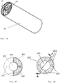
Fig. 2A is a perspective view of the target according to an embodiment of the invention, the target being placed in a container adapted to be placed in a reactor; -
Fig. 2B shows the same embodiment in the cross section; -
Fig. 2C shows the same embodiment in the longitudinal section; -
Fig. 3 shows a flowchart of a method of designing a target according to the invention; -
Fig. 4A shows a container with the target in the longitudinal section; -
Fig. 4B is a perspective view of the container; - Fig. C is a partial cross-sectional view of the target with a lid;
-
Fig. 4D is a cross-sectional view of the target with a longitudinal section line A-A; -
Fig. 4E is a perspective view of the target;and -
Fig. 4F shows the longitudinal section of the target through the line A-A. - A process of producing molybdenum 99 in an embodiment of the invention proceeds in steps according to the flowchart illustrated in
Fig. 1 . The process begins withstep 101 of the preparation of the construction material for thetarget 200. This material is a granulated alloy of LEU and aluminum. - The
target 200 is fabricated in thefabrication step 102. The selective laser sintering (SLS) technique has proven well to fabricate uranium targets. The selective laser melting (SLM), also known as direct metal laser melting (DMLM) or laser power bed fusion (LPBF) also works well. In both of these techniques, non-irradiated LEU powder particles are applied with shaping head and successively fused by selectively heating the powder with a laser. Unused material is recovered. - In the laser melting process, only part of the applied powder or granulate is fused. The excess falls off. This excess unused material is recovered in
step 110. It is reusable enriched uranium. - In the step of fabricating 102 the
target 200 from the construction material, in an additive process, so-called 3D printing, the construction material is applied using a moving head to form an openwork structure having its volume filled in accordance with an infill pattern of a model of thetarget 200. - The model is selected according to the shape of the available container intended to contain the target, to be filled with helium, and to be placed in a reactor chamber. Such containers are usually ready-made and optimized for a given reactor. Depending on the reactor type, it is possible to irradiate a different number of container units. It is important to fully utilize the container space - for the model of the target a margin of lower than 0.5 millimeters in relation to the internal dimensions of the container is assumed.
- Thanks to the use of the 3D printing technique, the effective density of the model can be adjusted within a wide range having an upper bound determined by the density of the printed material (uranium) and a lower bound determined by the mechanical strength of the structure. In the 3D printing technique, the design of an infill with a given percentage of density is a routine task largely performed by software.
- The infill is usually a repeating structure - a cell used to take up space within the model. There may be empty space inside the cell and between cells. By changing the type and size of the infill cell, one can change the effective density of the model. Common types of infill patterns include: honeycomb, spatial honeycomb, zigzag, concentric. Cellular infill patterns such as honeycomb show good strength.
- In the embodiment of the invention, the target is fabricated for the given
container 206 adapted to be placed in a reactor, shown in a section inFig. 2A and in a perspective inFig. 2B . In thecontainer 206 there is thetarget 200 closed by alid 205. The container is provided with apin 207 for positioning in a reactor. - The structure of the
target 200 shown in figures is openwork and adapted to the shape of thecontainer 206. Thecontainer 206 shown in figures has the following internal dimensions: a height of 142 mm and a radius of 22 mm. - The free space in the container shown in a section in
Fig. 2A has an inner radius of 10.5 mm and an outer radius of 21 mm. Thetarget 200 shown inFig. 2B has the outer dimensions adapted to the container with a margin of 1 mm on each side and is provided with 8 cooling water channels. The channels are arranged axially, but they can also be routed in other ways. Thetarget 200 was printed by a 3D printing process with a base cell of the infill pattern 1 mm in size. The design of thetarget 200 has a volume of 57305 mm3 and contains approximately 21 grams of U-235 enriched at 3.5%. - Both the
target 200 and thelid 205 are provided withchannels 203 substantially parallel to the axis of thecontainer 206 and the axis of thetarget 200. The target is provided with acentral hole 201 adapted to receive thepositioning pin 207. This ensures a repeatable positioning of thetarget 200 in a neutron beam. - The voids of the openwork structure of the
target 200 are provided asaxial holes 202. These holes are arranged in a random manner. Their diameters range from 0.5 to 3 mm. This is a compromise since finer holes increase the mechanical strength of the structure, while larger holes facilitate cooling by flow of gas during theirradiation step 104. The voids may also be arranged in some other manner to guide the gas in a specific manner through the volume of the target. - The method of the invention allows one to fabricate targets adapted to different types of containers and different uranium enrichment degrees. Since the radiation may be utilized in an optimal manner, it is possible to work with uranium with lower enrichment degree.
- For example, if a cylindrical container with an inside diameter of 20.5 mm and a height of 40.5 mm is available, a cylindrical model of the target with a diameter of 20 mm and a height of 40 mm is assumed. The volume of the target is 12.566 cm3. The size of the target and its degree of openwork can be adapted to the uranium enrichment degree and the amount of uranium 235 needed in the process. In particular, the method works well with relatively safe low enriched uranium - at the level of 0+ to 19.75%.
- Taking LEU with 5% enrichment degree as an available material and assuming that 2 g of uranium 235 is to be obtained, translates to the required target mass of 40 g, because 2 g is 5% of 40 g which is the total mass of uranium (238 +235) in the target.
- The mass of 40 g of uranium with a density of 19.05 g/cm3 corresponds to a volume of 2.01 cm3. Thus, the filling ratio of the usable volume of the container equals 2.01 / 12.566 = 16.7%.
- For a good utilization of a reactor beam it is essential to fill the entire volume of the container. To meet this condition, an openwork structure is fabricated with an average density equal to 16.7% of that of uranium. The skeleton of the openwork structure of the target takes 0.167 of the volume and the voids in the form of
axial holes 202 and theaxial hole 201 take 0.833 of the volume. As a first approximation, a structure with a uniform average effective density can be used. However, other preferred designs are available. Cylindrical structures with holes running parallel to the axis of the cylinder and arranged in its cross-section work well. Changing the size of the holes allows one not only to adjust the amount of nuclear material (including in particular the U-235 isotope), but also other features of the target. - The
target 200 according to another embodiment, placed in thecontainer 206, is shown in a section inFig. 4A and in a perspective inFig. 4B . In thepacking step 103, theopenwork target 200 is placed in thecontainer 206, which is filled with helium and closed. The helium pressure in the container is usually kept above the atmospheric pressure to ensure tightness. This assures that the helium in which the target is held is not contaminated.Fig. 4C presents the target and the container in a partial cross section showing thechannels 203 and thevoids 202 in the openwork structure of the target. The channels and voids are also visible inFig. 4D showing a cross section of thetarget 200. A longitudinal section is shown inFig. 4F . As it is shown inFig. 4E , the openwork structure of the target can be secured with analuminum shield 204. - The
container 206 is placed in a reactor and exposed to radiation in theirradiation step 104. By matching the dimensions of the target to the dimensions of the container, the radiation of the reactor is better utilized. - The effective density of the infill of the target's openwork structure can be adjusted to match the radiation distribution in the step of creating the model of the target.
- The irradiation duration depends on the operating cycle and characteristics of the reactor. For a given target with a fixed content of uranium 235 reacting with neutrons, the efficiency of the process depends on the neutron flux at the location where the container is placed and on the neutrons energy distribution. The irradiation cross section for U235 + n reactions depends on the neutron energy, so the energy distribution in the beam is important for the process.
- After irradiation, the
target 200 is removed from the container in the unpackingstep 105 and prepared for transportation. In the unpackingstep 105, targets made of granules introduce an additional risk of possible scattering. When the invention is used, this risk is relatively less due to the fact that the openwork structure of thetarget 200 is mechanically strong enough to not to spatter or scatter even under impact loads such as after a fall. The risk of spreading of the highly radioactive material when the container with the cooling gas is being opened and the target is being removed is minimized. - Next, the
target 200 is transported from the reactor to the laboratory. Thetransport step 106 should be kept as short as possible, so it is best if the laboratory is close to the reactor. In such a case, the losses due to the decay of molybdenum 99 are decreased, and the risk inherent in the transport of radioactive materials is reduced. - The laboratory performs the step of
chemical treatment 107 of the target and themolybdenum extraction step 108 as disclosed inUS Patent 3,799,883 . A person skilled in the art is routinely able to propose other methods for obtaining molybdenum 99. - The chemical treatment may be carried out in a way that allows one to recover 109 uranium from the waste after obtaining molybdenum and reuse it. The concept of recovering irradiated materials and using them to make another targets is disclosed in US patent application
US20140226774 . The uranium recovered in this way is less enriched, therefore it may be necessary to mix 111 it with some more enriched uranium to obtain the correct enrichment degree. An applicable chemical treatment method is also disclosed in Chapter 2. "Molybdenum-99 / Technetium-99m Production and Use" of the book entitled National Research Council. 2009. Medical Isotope Production Without Highly Enriched Uranium. Washington, DC: The National Academies Press. https://doi.org/10.17226/12569. - Due to the fact that the irradiation cross section for the U235+n reactions depends on the neutron energy, the energy distribution in the beam is important for the process. A direct consequence of the inhomogeneous beam energy distribution is that the simplest, regular, openwork spatial structures of targets may result in suboptimal process efficiency.
- According to the invention, the target is fabricated according to the model in an additive process - the so-called 3D printing. The advantage of the invention that it is possible to carry out dedicated calculations to optimize both the effective density and the shape of the target for a given type of reactor, for example using software that simulates the interaction of neutrons with the target. As a consequence, the spatial structure of the target can be adapted in a convenient process of rapid prototyping including simulation calculations to the planned process parameters, to the specific chambers or channels of a given reactor and to the specific containers.
- Better effects can be achieved by optimizing the model of the openwork structure of the target.
- The
boundary conditions 300 for designing the target according to the invention are: - composition of the LEU material of the target;
- container dimensions;
- process parameters - timing and intensity of irradiation;
- energy distribution in the beam at the location where the container is placed in the reactor chamber.
- Next, based on the design assumptions of the model, initial conditions and constraints of optimization are set 301 and the model is generated 302.
- The generated model is subjected to
irradiation simulation 303, and simulation returns the amount of molybdenum 99 that can be obtained for a given shape of the openwork structure of the target. For this purpose, one can use ready-made simulators developed by the Nuclear Energy Agency (NEA), https://www.oecd-nea.org/, and Los Alamos National Laboratory, e.g. the MCNP software package. - The results of the irradiation simulation are fed to the optimizer, which determines the target's shape changes 307 in the
optimization process 305, the changes being taken into account when the next model to simulate is generated 302. - There are methods and even software packages as well as parameterization data sets including cross sections for determining the amounts of obtained specific isotopes. Such programs are available, for example, through the Nuclear Energy Agency (NEA) https://www.oecd-nea.org/ or Los Alamos National Laboratory (MCNP package used by NCBJ). In this situation, it can be clearly stated that the person skilled in the art is able to adjust the particular arrangement of target and voids to a given reactor.
- Additionally, a
thermodynamic simulation step 304 can be introduced to facilitate the control of the temperature during irradiation and to take it into account in theoptimization 305. - The goal function of the
optimization process 305 is the amount of obtained molybdenum 99 determined in thestep 306 of retrieving from the irradiation simulation results. The temperature values determined in the thermodynamic simulation are compared with the given boundary conditions, i.e. the temperatures safe in a given reactor. - The model subjected to the optimization is adapted to the dimensions of the container, which in turn is adapted to the specific reactor. Although typically the containers are cylindrical in shape with the
positioning pin 207, there is considerable freedom to shape the model using various known infill patterns with different cell sizes. In addition, channels that facilitate cooling can be provided in the openwork structure. - Having read this description, a person skilled in the art of 3D printing will be able to easily propose numerous alternative openwork structures including spatial lattices, mesh structures or porous structures. Having read this description, a person skilled in the art will be able to propose numerous adequate optimization techniques, and on the basis of literature and experimental data, to develop other techniques for simulating the beam distribution or gas cavitation. Accordingly, the examples provided are to be considered merely illustrative of the scope of the invention and are not intended to limit the scope of protection as defined in the appended claims.
Claims (12)
- A method of fabricating a target (200) with predetermined mass and volume from low-enriched uranium, in which:in a material preparation step (101), a powdered or granular construction material comprising low-enriched uranium is prepared;in a fabrication step (102), the target (200) is made of said construction material, the target (200) having a shape adopted enclosing it in a container to be placed in a reactor, whereinthe fabrication step (102) is carried out in an additive process by applying successive layers of the construction material and selectively heating by means of a laser,characterized in thatprior to the fabrication of the target (200), there is created a digital model of the target (200) with dimensions that enable fitting into the space inside the container and a volume filled with an infill pattern having effective density lower than 80% of the uranium density, whereinsaid model defines an openwork cohesive body.
- Method according to the claim 1 characterized in that the model of the target (200) is formed with dimensions substantially matching the dimensions of the container such that the model fills the container with a margin ranging from 0.5 mm to 2 mm in each dimension such that the volume of the model substantially corresponds to the volume of the container, and arrangement of voids and the infill pattern of the openwork structure are selected so as to ensure the assumed mass of the target (200) for a given volume.
- Method according to the claim 1 or 2 characterized in that the arrangement of the voids in the structure of the target (200) and the distribution of the effective density of the infill pattern are selected in the steps of simulation (303) and optimization (305) of the absorption of a given neutron flux.
- Method according to the claim 1, 2 or 3 characterized in that the arrangement of the voids in the structure of the target (200) is selected by simulating and optimizing the gas flow.
- Method according to any of the claims 1 to 4 characterized in that during the additive process unused granular material is collected in the recovery step (110) and stored for reuse.
- A process of producing molybdenum 99 comprising
a step of fabricating (102) a target (200) from construction material containing low-enriched uranium,
a step of packing (103) the target (200) into a container,
a step of irradiating (104) by placing the container with the target (200) in a reactor followed by
an unpacking step (105),
a transport step (106),
and a step of chemical treatment (107) of the target for obtaining (108) molybdenum 99, characterized in that the step of fabricating (102) a target is carrier out as specified any of the claims 1 to 5. - Process according to the claim 6 characterized in that during or after the chemical treatment (107), unused uranium is recovered (109) and reused in the preparation of construction material.
- Process according to the claim 7 characterized in that uranium recovered in the recovery step (109) is used to prepare the construction material by mixing with enriched uranium.
- A target (200) made of a material containing low-enriched uranium for placing in a reactor characterized in that it has an openwork cohesive structure made with an infill pattern giving the effective density of less than 80%.
- The target (200) according to the claim 9 characterized in that it is shaped like a hollow cylinder with a central hole (201).
- The target (200) according to the claim 10 characterized in that the hollow cylinder is provided with additional channels (203).
- The target (200) according to the claim 9 or 10 or 11 characterized in that the openwork structure is made according to a mathematical model obtained as a result of optimization in an additive process by applying successive layers of a construction material containing low-enriched uranium and selectively heating this construction material with a laser.
Priority Applications (3)
| Application Number | Priority Date | Filing Date | Title |
|---|---|---|---|
| EP20461568.6A EP3985686B1 (en) | 2020-10-14 | 2020-10-14 | Method of preparation of the uranium target for the production of molybdenum, molybdenum production process and the uranium target for the production of molybdenum |
| PL20461568.6T PL3985686T3 (en) | 2020-10-14 | 2020-10-14 | Method of preparation of the uranium target for the production of molybdenum, molybdenum production process and the uranium target for the production of molybdenum |
| PCT/IB2021/059352 WO2022079600A1 (en) | 2020-10-14 | 2021-10-12 | A method of fabricating a uranium target for producing molybdenum, a process of producing molybdenum, and a uranium target for producing molybdenum |
Applications Claiming Priority (1)
| Application Number | Priority Date | Filing Date | Title |
|---|---|---|---|
| EP20461568.6A EP3985686B1 (en) | 2020-10-14 | 2020-10-14 | Method of preparation of the uranium target for the production of molybdenum, molybdenum production process and the uranium target for the production of molybdenum |
Publications (2)
| Publication Number | Publication Date |
|---|---|
| EP3985686A1 true EP3985686A1 (en) | 2022-04-20 |
| EP3985686B1 EP3985686B1 (en) | 2022-11-30 |
Family
ID=73835541
Family Applications (1)
| Application Number | Title | Priority Date | Filing Date |
|---|---|---|---|
| EP20461568.6A Active EP3985686B1 (en) | 2020-10-14 | 2020-10-14 | Method of preparation of the uranium target for the production of molybdenum, molybdenum production process and the uranium target for the production of molybdenum |
Country Status (3)
| Country | Link |
|---|---|
| EP (1) | EP3985686B1 (en) |
| PL (1) | PL3985686T3 (en) |
| WO (1) | WO2022079600A1 (en) |
Citations (9)
| Publication number | Priority date | Publication date | Assignee | Title |
|---|---|---|---|---|
| US3799883A (en) | 1971-06-30 | 1974-03-26 | Union Carbide Corp | Production of high purity fission product molybdenum-99 |
| WO2006000104A1 (en) | 2004-06-29 | 2006-01-05 | Triumf, Operating As A Joint Venture By The Governors Of The University Of Alberta, The University Of British Columbia, Carleton University, Simon Fraser University, The University Of Toronto, And The | Forced convection target assembly |
| US20120027152A1 (en) | 2010-07-29 | 2012-02-02 | of Oregon State | Isotope production target |
| EP2681744A1 (en) * | 2011-03-04 | 2014-01-08 | Korea Atomic Energy Research Institute | Method of preparing plate-shaped high-density low-enriched uranium dispersion target and high-density low-enriched uranium target prepared thereby |
| RU2511215C1 (en) * | 2012-10-02 | 2014-04-10 | Открытое акционерное общество "Государственный научный центр Научно-исследовательский институт атомных реакторов" | Target for producing mo-99 isotope |
| US20140226774A1 (en) | 2013-01-10 | 2014-08-14 | Thorenco Medical Isotopes Llc | Production of actinium-227 and thorium-228 from radium-226 to supply alpha-emitting isotopes radium-223, thorium-227, radium-224, bismuth-212 |
| WO2016081056A1 (en) | 2014-11-19 | 2016-05-26 | General Electric Company | Target body for an isotope production system and method of using the same |
| KR101674883B1 (en) | 2015-12-10 | 2016-11-11 | 한국원자력연구원 | Preparation method of high enriched uranium target and the high enriched uranium target thereby |
| CN109147965A (en) * | 2018-08-20 | 2019-01-04 | 中国原子能科学研究院 | A kind of more single sheet free modular slightly enriched uranium uranium foil target parts |
-
2020
- 2020-10-14 EP EP20461568.6A patent/EP3985686B1/en active Active
- 2020-10-14 PL PL20461568.6T patent/PL3985686T3/en unknown
-
2021
- 2021-10-12 WO PCT/IB2021/059352 patent/WO2022079600A1/en not_active Ceased
Patent Citations (9)
| Publication number | Priority date | Publication date | Assignee | Title |
|---|---|---|---|---|
| US3799883A (en) | 1971-06-30 | 1974-03-26 | Union Carbide Corp | Production of high purity fission product molybdenum-99 |
| WO2006000104A1 (en) | 2004-06-29 | 2006-01-05 | Triumf, Operating As A Joint Venture By The Governors Of The University Of Alberta, The University Of British Columbia, Carleton University, Simon Fraser University, The University Of Toronto, And The | Forced convection target assembly |
| US20120027152A1 (en) | 2010-07-29 | 2012-02-02 | of Oregon State | Isotope production target |
| EP2681744A1 (en) * | 2011-03-04 | 2014-01-08 | Korea Atomic Energy Research Institute | Method of preparing plate-shaped high-density low-enriched uranium dispersion target and high-density low-enriched uranium target prepared thereby |
| RU2511215C1 (en) * | 2012-10-02 | 2014-04-10 | Открытое акционерное общество "Государственный научный центр Научно-исследовательский институт атомных реакторов" | Target for producing mo-99 isotope |
| US20140226774A1 (en) | 2013-01-10 | 2014-08-14 | Thorenco Medical Isotopes Llc | Production of actinium-227 and thorium-228 from radium-226 to supply alpha-emitting isotopes radium-223, thorium-227, radium-224, bismuth-212 |
| WO2016081056A1 (en) | 2014-11-19 | 2016-05-26 | General Electric Company | Target body for an isotope production system and method of using the same |
| KR101674883B1 (en) | 2015-12-10 | 2016-11-11 | 한국원자력연구원 | Preparation method of high enriched uranium target and the high enriched uranium target thereby |
| CN109147965A (en) * | 2018-08-20 | 2019-01-04 | 中国原子能科学研究院 | A kind of more single sheet free modular slightly enriched uranium uranium foil target parts |
Non-Patent Citations (1)
| Title |
|---|
| "National Research Council", 2009, THE NATIONAL ACADEMIES PRESS, article "Molybdenum-99 / Technetium-99m Production and Use" |
Also Published As
| Publication number | Publication date |
|---|---|
| WO2022079600A1 (en) | 2022-04-21 |
| EP3985686B1 (en) | 2022-11-30 |
| PL3985686T3 (en) | 2023-01-16 |
Similar Documents
| Publication | Publication Date | Title |
|---|---|---|
| EP2956944B1 (en) | Nuclear reactor target assemblies and methods for producing isotopes, modifying materials within target material, and/or characterizing material within a target material | |
| US10026514B2 (en) | Canister apparatus and basket for transporting, storing and/or supporting spent nuclear fuel | |
| CN103038831A (en) | Isotope production target | |
| EP1573749B1 (en) | System and method for radioactive waste destruction | |
| CN114556491A (en) | Modular radioisotope generation package and related methods | |
| RU2645718C2 (en) | Method of developing radioactive isotopes in nuclear reactor on quick neutrons | |
| EP3985686B1 (en) | Method of preparation of the uranium target for the production of molybdenum, molybdenum production process and the uranium target for the production of molybdenum | |
| CN107622807A (en) | It is a kind of to produce radioisotopic device and method with phot-neutron source | |
| Kim et al. | SANTA: A safety analysis code for neutron absorbers in spent nuclear fuel pools | |
| RU2035076C1 (en) | Source of gamma radiation provided with active core and method for manufacturing same | |
| US7804077B2 (en) | Passive actinide self-burner | |
| US12254997B2 (en) | Fuel fabrication process for radioisotope thermoelectric generators | |
| JPH0886893A (en) | Complete combustion reactor | |
| Sayareh et al. | Theoretical calculations for the production of 99Mo using natural uranium in Iran | |
| Sairanbayev et al. | Optimization of conditions for topaz irradiation in the WWR-K reactor | |
| RU2557616C1 (en) | Method of conversion of nuclear energy into heat energy and device for its implementation (versions) | |
| KR20250025680A (en) | The use of subcritical neutron multiplication driven by an electron neutron generator to produce radioisotopes. | |
| WO2014126623A2 (en) | Dry phase reactor for generating medical isotopes | |
| RU2769482C9 (en) | Irradiation device for the production of co-60 isotope in a fast neutron reactor | |
| Pesic et al. | Criticality safety evaluation for TWR-S fuel assembly transportation using TK-S16 containers | |
| US20110080986A1 (en) | Method of transmuting very long lived isotopes | |
| RU2200353C1 (en) | Method for decontaminating radioactive wastes | |
| Leskinen et al. | Characterisation of FiR1 TRIGA Mark II Research Reactor–A Combination of Modelling and Experimental | |
| Abrefah | Neutronics and Dose Calculation for Prospective Spent Nuclear Fuel Cask for Ghana Research Reactor-1 Facility. | |
| US9613726B2 (en) | Systems and methods for reducing the storage time of spent nuclear fuel |
Legal Events
| Date | Code | Title | Description |
|---|---|---|---|
| PUAI | Public reference made under article 153(3) epc to a published international application that has entered the european phase |
Free format text: ORIGINAL CODE: 0009012 |
|
| STAA | Information on the status of an ep patent application or granted ep patent |
Free format text: STATUS: REQUEST FOR EXAMINATION WAS MADE |
|
| 17P | Request for examination filed |
Effective date: 20210514 |
|
| AK | Designated contracting states |
Kind code of ref document: A1 Designated state(s): AL AT BE BG CH CY CZ DE DK EE ES FI FR GB GR HR HU IE IS IT LI LT LU LV MC MK MT NL NO PL PT RO RS SE SI SK SM TR |
|
| GRAP | Despatch of communication of intention to grant a patent |
Free format text: ORIGINAL CODE: EPIDOSNIGR1 |
|
| STAA | Information on the status of an ep patent application or granted ep patent |
Free format text: STATUS: GRANT OF PATENT IS INTENDED |
|
| INTG | Intention to grant announced |
Effective date: 20220628 |
|
| GRAS | Grant fee paid |
Free format text: ORIGINAL CODE: EPIDOSNIGR3 |
|
| GRAA | (expected) grant |
Free format text: ORIGINAL CODE: 0009210 |
|
| STAA | Information on the status of an ep patent application or granted ep patent |
Free format text: STATUS: THE PATENT HAS BEEN GRANTED |
|
| AK | Designated contracting states |
Kind code of ref document: B1 Designated state(s): AL AT BE BG CH CY CZ DE DK EE ES FI FR GB GR HR HU IE IS IT LI LT LU LV MC MK MT NL NO PL PT RO RS SE SI SK SM TR |
|
| REG | Reference to a national code |
Ref country code: CH Ref legal event code: EP Ref country code: GB Ref legal event code: FG4D |
|
| REG | Reference to a national code |
Ref country code: AT Ref legal event code: REF Ref document number: 1535309 Country of ref document: AT Kind code of ref document: T Effective date: 20221215 Ref country code: DE Ref legal event code: R096 Ref document number: 602020006627 Country of ref document: DE |
|
| REG | Reference to a national code |
Ref country code: IE Ref legal event code: FG4D |
|
| REG | Reference to a national code |
Ref country code: NL Ref legal event code: FP |
|
| REG | Reference to a national code |
Ref country code: LT Ref legal event code: MG9D |
|
| PG25 | Lapsed in a contracting state [announced via postgrant information from national office to epo] |
Ref country code: SE Free format text: LAPSE BECAUSE OF FAILURE TO SUBMIT A TRANSLATION OF THE DESCRIPTION OR TO PAY THE FEE WITHIN THE PRESCRIBED TIME-LIMIT Effective date: 20221130 Ref country code: PT Free format text: LAPSE BECAUSE OF FAILURE TO SUBMIT A TRANSLATION OF THE DESCRIPTION OR TO PAY THE FEE WITHIN THE PRESCRIBED TIME-LIMIT Effective date: 20230331 Ref country code: NO Free format text: LAPSE BECAUSE OF FAILURE TO SUBMIT A TRANSLATION OF THE DESCRIPTION OR TO PAY THE FEE WITHIN THE PRESCRIBED TIME-LIMIT Effective date: 20230228 Ref country code: LT Free format text: LAPSE BECAUSE OF FAILURE TO SUBMIT A TRANSLATION OF THE DESCRIPTION OR TO PAY THE FEE WITHIN THE PRESCRIBED TIME-LIMIT Effective date: 20221130 Ref country code: FI Free format text: LAPSE BECAUSE OF FAILURE TO SUBMIT A TRANSLATION OF THE DESCRIPTION OR TO PAY THE FEE WITHIN THE PRESCRIBED TIME-LIMIT Effective date: 20221130 Ref country code: ES Free format text: LAPSE BECAUSE OF FAILURE TO SUBMIT A TRANSLATION OF THE DESCRIPTION OR TO PAY THE FEE WITHIN THE PRESCRIBED TIME-LIMIT Effective date: 20221130 |
|
| REG | Reference to a national code |
Ref country code: AT Ref legal event code: MK05 Ref document number: 1535309 Country of ref document: AT Kind code of ref document: T Effective date: 20221130 |
|
| PG25 | Lapsed in a contracting state [announced via postgrant information from national office to epo] |
Ref country code: RS Free format text: LAPSE BECAUSE OF FAILURE TO SUBMIT A TRANSLATION OF THE DESCRIPTION OR TO PAY THE FEE WITHIN THE PRESCRIBED TIME-LIMIT Effective date: 20221130 Ref country code: LV Free format text: LAPSE BECAUSE OF FAILURE TO SUBMIT A TRANSLATION OF THE DESCRIPTION OR TO PAY THE FEE WITHIN THE PRESCRIBED TIME-LIMIT Effective date: 20221130 Ref country code: IS Free format text: LAPSE BECAUSE OF FAILURE TO SUBMIT A TRANSLATION OF THE DESCRIPTION OR TO PAY THE FEE WITHIN THE PRESCRIBED TIME-LIMIT Effective date: 20230330 Ref country code: HR Free format text: LAPSE BECAUSE OF FAILURE TO SUBMIT A TRANSLATION OF THE DESCRIPTION OR TO PAY THE FEE WITHIN THE PRESCRIBED TIME-LIMIT Effective date: 20221130 Ref country code: GR Free format text: LAPSE BECAUSE OF FAILURE TO SUBMIT A TRANSLATION OF THE DESCRIPTION OR TO PAY THE FEE WITHIN THE PRESCRIBED TIME-LIMIT Effective date: 20230301 |
|
| PG25 | Lapsed in a contracting state [announced via postgrant information from national office to epo] |
Ref country code: SM Free format text: LAPSE BECAUSE OF FAILURE TO SUBMIT A TRANSLATION OF THE DESCRIPTION OR TO PAY THE FEE WITHIN THE PRESCRIBED TIME-LIMIT Effective date: 20221130 Ref country code: RO Free format text: LAPSE BECAUSE OF FAILURE TO SUBMIT A TRANSLATION OF THE DESCRIPTION OR TO PAY THE FEE WITHIN THE PRESCRIBED TIME-LIMIT Effective date: 20221130 Ref country code: EE Free format text: LAPSE BECAUSE OF FAILURE TO SUBMIT A TRANSLATION OF THE DESCRIPTION OR TO PAY THE FEE WITHIN THE PRESCRIBED TIME-LIMIT Effective date: 20221130 Ref country code: DK Free format text: LAPSE BECAUSE OF FAILURE TO SUBMIT A TRANSLATION OF THE DESCRIPTION OR TO PAY THE FEE WITHIN THE PRESCRIBED TIME-LIMIT Effective date: 20221130 Ref country code: CZ Free format text: LAPSE BECAUSE OF FAILURE TO SUBMIT A TRANSLATION OF THE DESCRIPTION OR TO PAY THE FEE WITHIN THE PRESCRIBED TIME-LIMIT Effective date: 20221130 Ref country code: AT Free format text: LAPSE BECAUSE OF FAILURE TO SUBMIT A TRANSLATION OF THE DESCRIPTION OR TO PAY THE FEE WITHIN THE PRESCRIBED TIME-LIMIT Effective date: 20221130 |
|
| PG25 | Lapsed in a contracting state [announced via postgrant information from national office to epo] |
Ref country code: SK Free format text: LAPSE BECAUSE OF FAILURE TO SUBMIT A TRANSLATION OF THE DESCRIPTION OR TO PAY THE FEE WITHIN THE PRESCRIBED TIME-LIMIT Effective date: 20221130 Ref country code: AL Free format text: LAPSE BECAUSE OF FAILURE TO SUBMIT A TRANSLATION OF THE DESCRIPTION OR TO PAY THE FEE WITHIN THE PRESCRIBED TIME-LIMIT Effective date: 20221130 |
|
| REG | Reference to a national code |
Ref country code: DE Ref legal event code: R097 Ref document number: 602020006627 Country of ref document: DE |
|
| PLBE | No opposition filed within time limit |
Free format text: ORIGINAL CODE: 0009261 |
|
| STAA | Information on the status of an ep patent application or granted ep patent |
Free format text: STATUS: NO OPPOSITION FILED WITHIN TIME LIMIT |
|
| 26N | No opposition filed |
Effective date: 20230831 |
|
| PG25 | Lapsed in a contracting state [announced via postgrant information from national office to epo] |
Ref country code: SI Free format text: LAPSE BECAUSE OF FAILURE TO SUBMIT A TRANSLATION OF THE DESCRIPTION OR TO PAY THE FEE WITHIN THE PRESCRIBED TIME-LIMIT Effective date: 20221130 |
|
| PG25 | Lapsed in a contracting state [announced via postgrant information from national office to epo] |
Ref country code: IT Free format text: LAPSE BECAUSE OF FAILURE TO SUBMIT A TRANSLATION OF THE DESCRIPTION OR TO PAY THE FEE WITHIN THE PRESCRIBED TIME-LIMIT Effective date: 20221130 Ref country code: MC Free format text: LAPSE BECAUSE OF FAILURE TO SUBMIT A TRANSLATION OF THE DESCRIPTION OR TO PAY THE FEE WITHIN THE PRESCRIBED TIME-LIMIT Effective date: 20221130 |
|
| REG | Reference to a national code |
Ref country code: CH Ref legal event code: PL |
|
| REG | Reference to a national code |
Ref country code: BE Ref legal event code: MM Effective date: 20231031 |
|
| PG25 | Lapsed in a contracting state [announced via postgrant information from national office to epo] |
Ref country code: LU Free format text: LAPSE BECAUSE OF NON-PAYMENT OF DUE FEES Effective date: 20231014 |
|
| PG25 | Lapsed in a contracting state [announced via postgrant information from national office to epo] |
Ref country code: LU Free format text: LAPSE BECAUSE OF NON-PAYMENT OF DUE FEES Effective date: 20231014 |
|
| PG25 | Lapsed in a contracting state [announced via postgrant information from national office to epo] |
Ref country code: CH Free format text: LAPSE BECAUSE OF NON-PAYMENT OF DUE FEES Effective date: 20231031 |
|
| PG25 | Lapsed in a contracting state [announced via postgrant information from national office to epo] |
Ref country code: CH Free format text: LAPSE BECAUSE OF NON-PAYMENT OF DUE FEES Effective date: 20231031 |
|
| PG25 | Lapsed in a contracting state [announced via postgrant information from national office to epo] |
Ref country code: BE Free format text: LAPSE BECAUSE OF NON-PAYMENT OF DUE FEES Effective date: 20231031 |
|
| PG25 | Lapsed in a contracting state [announced via postgrant information from national office to epo] |
Ref country code: IE Free format text: LAPSE BECAUSE OF NON-PAYMENT OF DUE FEES Effective date: 20231014 |
|
| PG25 | Lapsed in a contracting state [announced via postgrant information from national office to epo] |
Ref country code: IE Free format text: LAPSE BECAUSE OF NON-PAYMENT OF DUE FEES Effective date: 20231014 |
|
| PG25 | Lapsed in a contracting state [announced via postgrant information from national office to epo] |
Ref country code: BG Free format text: LAPSE BECAUSE OF FAILURE TO SUBMIT A TRANSLATION OF THE DESCRIPTION OR TO PAY THE FEE WITHIN THE PRESCRIBED TIME-LIMIT Effective date: 20221130 |
|
| PG25 | Lapsed in a contracting state [announced via postgrant information from national office to epo] |
Ref country code: BG Free format text: LAPSE BECAUSE OF FAILURE TO SUBMIT A TRANSLATION OF THE DESCRIPTION OR TO PAY THE FEE WITHIN THE PRESCRIBED TIME-LIMIT Effective date: 20221130 |
|
| PG25 | Lapsed in a contracting state [announced via postgrant information from national office to epo] |
Ref country code: CY Free format text: LAPSE BECAUSE OF FAILURE TO SUBMIT A TRANSLATION OF THE DESCRIPTION OR TO PAY THE FEE WITHIN THE PRESCRIBED TIME-LIMIT; INVALID AB INITIO Effective date: 20201014 |
|
| PG25 | Lapsed in a contracting state [announced via postgrant information from national office to epo] |
Ref country code: HU Free format text: LAPSE BECAUSE OF FAILURE TO SUBMIT A TRANSLATION OF THE DESCRIPTION OR TO PAY THE FEE WITHIN THE PRESCRIBED TIME-LIMIT; INVALID AB INITIO Effective date: 20201014 |
|
| PGFP | Annual fee paid to national office [announced via postgrant information from national office to epo] |
Ref country code: NL Payment date: 20251003 Year of fee payment: 6 |
|
| PG25 | Lapsed in a contracting state [announced via postgrant information from national office to epo] |
Ref country code: TR Free format text: LAPSE BECAUSE OF FAILURE TO SUBMIT A TRANSLATION OF THE DESCRIPTION OR TO PAY THE FEE WITHIN THE PRESCRIBED TIME-LIMIT Effective date: 20221130 |
|
| PGFP | Annual fee paid to national office [announced via postgrant information from national office to epo] |
Ref country code: DE Payment date: 20251003 Year of fee payment: 6 |
|
| PGFP | Annual fee paid to national office [announced via postgrant information from national office to epo] |
Ref country code: GB Payment date: 20251002 Year of fee payment: 6 |
|
| PGFP | Annual fee paid to national office [announced via postgrant information from national office to epo] |
Ref country code: FR Payment date: 20251002 Year of fee payment: 6 |
|
| PGFP | Annual fee paid to national office [announced via postgrant information from national office to epo] |
Ref country code: PL Payment date: 20251002 Year of fee payment: 6 |
|
| PG25 | Lapsed in a contracting state [announced via postgrant information from national office to epo] |
Ref country code: MT Free format text: LAPSE BECAUSE OF NON-PAYMENT OF DUE FEES Effective date: 20231014 |