EP3985480A1 - Information processing apparatus and control method - Google Patents
Information processing apparatus and control method Download PDFInfo
- Publication number
- EP3985480A1 EP3985480A1 EP21196555.3A EP21196555A EP3985480A1 EP 3985480 A1 EP3985480 A1 EP 3985480A1 EP 21196555 A EP21196555 A EP 21196555A EP 3985480 A1 EP3985480 A1 EP 3985480A1
- Authority
- EP
- European Patent Office
- Prior art keywords
- main system
- image data
- input
- input area
- display
- Prior art date
- Legal status (The legal status is an assumption and is not a legal conclusion. Google has not performed a legal analysis and makes no representation as to the accuracy of the status listed.)
- Granted
Links
Images



Classifications
-
- G—PHYSICS
- G06—COMPUTING OR CALCULATING; COUNTING
- G06F—ELECTRIC DIGITAL DATA PROCESSING
- G06F3/00—Input arrangements for transferring data to be processed into a form capable of being handled by the computer; Output arrangements for transferring data from processing unit to output unit, e.g. interface arrangements
- G06F3/14—Digital output to display device ; Cooperation and interconnection of the display device with other functional units
- G06F3/1423—Digital output to display device ; Cooperation and interconnection of the display device with other functional units controlling a plurality of local displays, e.g. CRT and flat panel display
-
- G—PHYSICS
- G06—COMPUTING OR CALCULATING; COUNTING
- G06F—ELECTRIC DIGITAL DATA PROCESSING
- G06F3/00—Input arrangements for transferring data to be processed into a form capable of being handled by the computer; Output arrangements for transferring data from processing unit to output unit, e.g. interface arrangements
- G06F3/01—Input arrangements or combined input and output arrangements for interaction between user and computer
- G06F3/048—Interaction techniques based on graphical user interfaces [GUI]
- G06F3/0487—Interaction techniques based on graphical user interfaces [GUI] using specific features provided by the input device, e.g. functions controlled by the rotation of a mouse with dual sensing arrangements, or of the nature of the input device, e.g. tap gestures based on pressure sensed by a digitiser
- G06F3/0488—Interaction techniques based on graphical user interfaces [GUI] using specific features provided by the input device, e.g. functions controlled by the rotation of a mouse with dual sensing arrangements, or of the nature of the input device, e.g. tap gestures based on pressure sensed by a digitiser using a touch-screen or digitiser, e.g. input of commands through traced gestures
- G06F3/04886—Interaction techniques based on graphical user interfaces [GUI] using specific features provided by the input device, e.g. functions controlled by the rotation of a mouse with dual sensing arrangements, or of the nature of the input device, e.g. tap gestures based on pressure sensed by a digitiser using a touch-screen or digitiser, e.g. input of commands through traced gestures by partitioning the display area of the touch-screen or the surface of the digitising tablet into independently controllable areas, e.g. virtual keyboards or menus
-
- G—PHYSICS
- G06—COMPUTING OR CALCULATING; COUNTING
- G06F—ELECTRIC DIGITAL DATA PROCESSING
- G06F1/00—Details not covered by groups G06F3/00 - G06F13/00 and G06F21/00
- G06F1/16—Constructional details or arrangements
- G06F1/1613—Constructional details or arrangements for portable computers
- G06F1/1615—Constructional details or arrangements for portable computers with several enclosures having relative motions, each enclosure supporting at least one I/O or computing function
- G06F1/1616—Constructional details or arrangements for portable computers with several enclosures having relative motions, each enclosure supporting at least one I/O or computing function with folding flat displays, e.g. laptop computers or notebooks having a clamshell configuration, with body parts pivoting to an open position around an axis parallel to the plane they define in closed position
-
- G—PHYSICS
- G06—COMPUTING OR CALCULATING; COUNTING
- G06F—ELECTRIC DIGITAL DATA PROCESSING
- G06F3/00—Input arrangements for transferring data to be processed into a form capable of being handled by the computer; Output arrangements for transferring data from processing unit to output unit, e.g. interface arrangements
- G06F3/01—Input arrangements or combined input and output arrangements for interaction between user and computer
- G06F3/03—Arrangements for converting the position or the displacement of a member into a coded form
- G06F3/041—Digitisers, e.g. for touch screens or touch pads, characterised by the transducing means
- G06F3/0416—Control or interface arrangements specially adapted for digitisers
-
- G—PHYSICS
- G06—COMPUTING OR CALCULATING; COUNTING
- G06F—ELECTRIC DIGITAL DATA PROCESSING
- G06F3/00—Input arrangements for transferring data to be processed into a form capable of being handled by the computer; Output arrangements for transferring data from processing unit to output unit, e.g. interface arrangements
- G06F3/01—Input arrangements or combined input and output arrangements for interaction between user and computer
- G06F3/048—Interaction techniques based on graphical user interfaces [GUI]
- G06F3/0487—Interaction techniques based on graphical user interfaces [GUI] using specific features provided by the input device, e.g. functions controlled by the rotation of a mouse with dual sensing arrangements, or of the nature of the input device, e.g. tap gestures based on pressure sensed by a digitiser
- G06F3/0488—Interaction techniques based on graphical user interfaces [GUI] using specific features provided by the input device, e.g. functions controlled by the rotation of a mouse with dual sensing arrangements, or of the nature of the input device, e.g. tap gestures based on pressure sensed by a digitiser using a touch-screen or digitiser, e.g. input of commands through traced gestures
-
- G—PHYSICS
- G06—COMPUTING OR CALCULATING; COUNTING
- G06F—ELECTRIC DIGITAL DATA PROCESSING
- G06F3/00—Input arrangements for transferring data to be processed into a form capable of being handled by the computer; Output arrangements for transferring data from processing unit to output unit, e.g. interface arrangements
- G06F3/14—Digital output to display device ; Cooperation and interconnection of the display device with other functional units
-
- G—PHYSICS
- G09—EDUCATION; CRYPTOGRAPHY; DISPLAY; ADVERTISING; SEALS
- G09G—ARRANGEMENTS OR CIRCUITS FOR CONTROL OF INDICATING DEVICES USING STATIC MEANS TO PRESENT VARIABLE INFORMATION
- G09G2354/00—Aspects of interface with display user
-
- G—PHYSICS
- G09—EDUCATION; CRYPTOGRAPHY; DISPLAY; ADVERTISING; SEALS
- G09G—ARRANGEMENTS OR CIRCUITS FOR CONTROL OF INDICATING DEVICES USING STATIC MEANS TO PRESENT VARIABLE INFORMATION
- G09G2358/00—Arrangements for display data security
Definitions
- the present invention relates to an information processing apparatus and a control method.
- Patent Document 1 Japanese Unexamined Patent Application Publication No. 2015-233198
- the present invention has been made to solve the above-described problem, and an object of the invention is to provide an information processing apparatus and a control method that make it possible to achieve a virtual input device that provides a high degree of freedom while protecting confidentiality and privacy at the same time.
- a first aspect of the present invention is an information processing apparatus that includes: a display unit; a touch sensor section which is placed on the display unit and detects contact with an object on the display unit; a main system which performs processing based on an OS (Operating System); and an embedded system which is an independent embedded system different from the main system, generates image data of an input area for a virtual input device, outputs image data of the input area to the main system by using a general-purpose interface protected by the main system, and also outputs input information, which is based on detection information detected in the input area by the touch sensor section, as input information accepted by the virtual input device to the main system by using a general-purpose interface protected by the main system, wherein the main system displays, on the display unit, image data of the input area output by the embedded system.
- OS Operating System
- the embedded system may output input information accepted by the virtual input device to the main system by using a HID (Human Interface Device) class of a USB (Universal Serial Bus) interface, and may output image data of the input area to the main system by using a UVC (USB Video Class).
- HID Human Interface Device
- USB Universal Serial Bus
- the main system may send display position information indicating a display position of the input area in the display unit to the embedded system, and display image data of the input area output from the embedded system at a display position of the input area in the display unit, and the embedded system may set the input area on the basis of the display position information sent from the main system.
- the main system may send type information indicating a type of the virtual input device to the embedded system, and the embedded system may set a type of the input area on the basis of the type information sent from the main system.
- the embedded system may change image data of the input area according to feedback based on input information accepted by the virtual input device.
- the display unit may include a first display area displaying image data of a main screen of the main system and a second display area displaying image data that includes image data of the input area.
- a seventh aspect of the present invention is a control method for an information processing apparatus provided with a display unit; a touch sensor section which is placed on the display unit and detects contact with an object on the display unit; a main system which performs processing based on an OS (Operating System); and an embedded system which is an independent embedded system different from the main system, the control method including: a step in which the embedded system generates image data of an input area for a virtual input device and outputs image data of the input area to the main system by using a general-purpose interface protected by the main system, a step in which the main system displays, on the display unit, image data of the input area output by the embedded system; and a step in which the embedded system outputs input information, which is based on detection information detected in the input area by the touch sensor section, as input information accepted by the virtual input device to the main system by using a general-purpose interface protected by the main system.
- OS Operating System
- the above-described aspects of the present invention can achieve a virtual input device that provides a high degree of freedom while protecting confidentiality and privacy at the same time.
- FIG. 7 is a block diagram illustrating an example of the functional configuration of the laptop PC according to the second embodiment.
- FIG. 1 is an external view illustrating an example of a laptop PC 1 according to a first embodiment.
- a description will be given of the laptop PC 1 as an example of an information processing apparatus.
- the laptop PC 1 has a first chassis 101 and a second chassis 102, and is configured such that a side surface of one chassis (the first chassis 101) is engaged with a side surface of the other chassis (the second chassis 102) by a hinge mechanism, and the first chassis 101 can be rotated with respect to the second chassis 102 around the rotation axis of the hinge mechanism.
- the laptop PC 1 has a touch screen 14 and a display unit 15.
- the display unit 15 is placed on the first chassis 101 and functions as a main display unit.
- the touch screen 14 is placed on the second chassis 102, and includes a display section 141 and a touch sensor section 142.
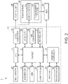
- FIG. 2 is a diagram illustrating an example of the major hardware configuration of the laptop PC 1 according to the present embodiment.
- the laptop PC 1 includes a CPU 11, a main memory 12, a video subsystem 13, the touch screen 14, the display unit 15, a chipset 21, a BIOS memory 22, a HDD 23, an audio system 24, a WLAN card 25, a USB connector 26, an imaging unit 27, an embedded controller 31, an input unit 32, a power circuit 33, and a MCU (Micro Control Unit) 40.
- the CPU 11, the main memory 12, the video subsystem 13, the chipset 21, the BIOS memory 22, the HDD 23, the audio system 24, the WLAN card 25, the USB connector 26, the imaging unit 27, the embedded controller 31, the input unit 32, and the power circuit 33 correspond to a main system 10 that performs the processing based on an OS (Operating System).
- OS Operating System
- the main system 10 executes various types of processing on the basis of, for example, Windows (registered trademark).
- the CPU (Central Processing Unit) 11 executes various types of arithmetic processing under program control to control the entire laptop PC 1.
- the main memory 12 is a writable memory that is used as an area for reading an executable program of the CPU 11 or as a work area for writing processing data of an executable program.
- the main memory 12 is composed of, for example, a plurality of DRAM (Dynamic Random Access Memory) chips.
- the executable program includes an OS, various drivers for hardware operation of peripheral devices, various services/utilities, application programs, and the like.
- the video subsystem 13 is a subsystem for implementing functions related to image display and includes a video controller.
- This video controller processes drawing instructions from the CPU 11, writes the processed drawing information to a video memory, reads the drawing information from the video memory, and outputs the read drawing information as drawing data (image data) to the display unit 15 and a display section 141.
- the video subsystem 13 outputs, for example, via HDMI (High-Definition Multimedia Interface (registered trademark)) or DP (Display Port).
- the touch screen 14 is placed on the second chassis 102 and includes the display section 141 and the touch sensor section 142, as illustrated in FIG. 1 .
- the display section 141 is, for example, a liquid crystal display or an e-paper, and displays image data on the display screen thereof.
- the touch sensor section 142 is placed, being superimposed on the display screen of the display section 141, and detects contact with an object (including a part of a human body) on the display screen of the display section 141.
- the touch sensor section 142 outputs contact position information indicating a contact position, which is the position of contact within a detection area on the display screen, to the MCU 40.
- the display unit 15 is placed on the first chassis 101, and functions as the main display unit of the laptop PC 1.
- the display unit 15 is, for example, a liquid crystal display or an organic EL display, and displays image data on the display screen.
- the chipset 21 includes controllers such as USB (Universal Serial Bus), serial ATA (AT Attachment), SPI (Serial Peripheral Interface) bus, PCI (Peripheral Component Interconnect) bus, PCI-Express bus, and LPC (Low Pin Count) bus, and a plurality of devices are connected thereto.
- controllers such as USB (Universal Serial Bus), serial ATA (AT Attachment), SPI (Serial Peripheral Interface) bus, PCI (Peripheral Component Interconnect) bus, PCI-Express bus, and LPC (Low Pin Count) bus, and a plurality of devices are connected thereto.
- USB Universal Serial Bus
- serial ATA AT Attachment
- SPI Serial Peripheral Interface
- PCI Peripheral Component Interconnect
- PCI-Express PCI-Express
- LPC Low Pin Count
- the BIOS (Basic Input/Output System) memory 22 is composed of, for example, an electrically rewritable nonvolatile memory such as an EEPROM (Electrically Erasable Programmable Read Only Memory) or a flash ROM.
- the BIOS memory 22 stores a BIOS, system firmware for controlling the embedded controller 31, and the like.
- the HDD (Hard Disk Drive) 23 (an example of a nonvolatile storage device) stores an OS, various drivers, various services/utilities, application programs, and various types of data.
- the audio system 24 records, reproduces, and outputs sound data.
- the WLAN (Wireless Local Area Network) card 25 is connected to a network by a wireless LAN to perform data communication. Upon receipt of data from the network, for example, the WLAN card 25 generates an event trigger indicating the receipt of data.
- the USB connector 26 is a connector for connecting a peripheral device or the like using the USB.
- the imaging unit 27 is, for example, a web camera, and captures images.
- the imaging unit 27 is connected with the chipset 21 through, for example, a USB interface.
- the embedded controller 31 is a one-chip microcomputer that monitors and controls various devices (peripheral devices, sensors, and the like) regardless of the system state of the laptop PC 1. Further, the embedded controller 31 has a power supply management function for controlling the power circuit 33.
- the embedded controller 31 is composed of a CPU, a ROM, a RAM and the like (not illustrated), and also includes multiple channel A/D input terminals, D/A output terminals, timers, and digital input/output terminals. Connected to the embedded controller 31 through the input/output terminals are, for example, the input unit 32, the power circuit 33, and the like, and the embedded controller 31 controls the operations thereof.
- the input unit 32 is, for example, a control switch such as a power switch.
- the power circuit 33 includes, for example, a DC/DC converter, a charge/discharge unit, a battery unit, an AC/DC adapter, and the like, and converts a DC voltage supplied from the AC/DC adapter or the battery unit into a plurality of voltages required to operate the laptop PC 1. Further, the power circuit 33 supplies power to each part of the laptop PC 1 according to the control by the embedded controller 31.
- the MCU 40 is, for example, a processor including a CPU and the like, and functions as an independent embedded system different from the main system 10 by executing built-in firmware.
- the MCU 40 is connected to the chipset 21 by, for example, a USB interface.
- the MCU 40 generates image data of an input area for a virtual input device, and outputs the image data of the input area to the main system 10 by using a general-purpose interface (e.g., UVC (USB Video Class)) protected by the main system 10.
- a general-purpose interface e.g., UVC (USB Video Class) protected by the main system 10.
- the MCU 40 outputs input information based on the detection information detected by the touch sensor section 142 in the input area as the input information accepted by the virtual input device to the main system 10 (the chipset 21) by using the general-purpose interface protected by the main system 10 (e.g., a HID (Human Interface Device) class of USB).
- the general-purpose interface protected by the main system 10 e.g., a HID (Human Interface Device) class of USB.
- FIG. 3 is a block diagram illustrating an example of the functional configuration of the laptop PC 1 according to the present embodiment.
- the laptop PC 1 includes the main system 10, the touch screen 14, and the MCU 40.
- FIG. 3 illustrates only the major functional configuration of the present embodiment related to the invention as the configuration of the laptop PC 1.
- the main system 10 includes a USB driver 51 and an OSK application 52.
- the USB driver 51 is a function section implemented by the CPU 11 and the chipset 21, and controls a USB interface.
- a HID class and a VIDEO class (UVC) are used as the USB interfaces.
- the OSK application 52 is, for example, an API (Application Programming Interface) for using an OSK.
- the OSK application 52 first uses the HID class of the USB driver 51 to send OSK information, which is OSK setting information, to the MCU 40.
- OSK information includes, for example, type information indicating the type of a virtual input device, and display position information indicating the display position of an input area in the display section 141.
- the OSK application 52 receives image data of the OSK (hereinafter referred to as "the OSK image data") output from the MCU 40 by using the VIDEO class of the USB driver 51, and causes the OSK image data to be displayed at the display position of the input area in the display section 141 mentioned above. For example, if the input area of the OSK is a part of the display section 141, then the OSK image data is overlaid on a part of the image data displayed on the display section 141 so as to generate display data, and the display data is output to the display section 141.
- the OSK application 52 uses the HID class of the USB driver 51 to receive input information such as a key code of the OSK from the MCU 40.
- the OSK application 52 When the OSK is operated, the OSK application 52 receives, from the MCU 40, feedback OSK image data based on the operation of the OSK by using the VIDEO class of the USB driver 51, and causes the feedback OSK image data to be displayed at the display section 141. Further, if the OSK image data has been compressed, then the OSK application 52 decompresses the compressed OSK image data and outputs the decompressed OSK image data to the display section 141.
- the MCU 40 includes an input processing section 41 and a display processing section 42.
- the input processing section 41 uses the HID class of the USB interface to receive the type information and the display position information from the main system 10, and sets the type of the input area of a virtual input device according to the type information and sets the input area of the virtual input device according to the display position information.
- the input processing section 41 stores the type of the input area and the setting information of the input area in a storage (not illustrated).
- the type information includes, for example, an OSK, a touchpad, a handwriting input device, and the like.
- the input processing section 41 outputs the received type information and display position information to the display processing section 42 to generate OSK image data.
- the input processing section 41 acquires detection information detected by the touch sensor section 142, and converts the detection information detected in the input area set as described above into input information such as a key code.
- the input processing section 41 uses the HID class of the USB interface to output the converted input information to the main system 10.
- the input processing section 41 outputs the detection information of the touch sensor section 142 to the display processing section 42 to generate the feedback OSK image data according to the detection information.
- the display processing section 42 generates the OSK image data on the basis of the type information and the display position information, and outputs the generated OSK image data to the main system 10 by using the VIDEO class (UVC) of the USB interface.
- the display processing section 42 may compress the generated OSK image data in a compression format such as JPEG (Joint Photographic Experts Group) and output the compressed OSK image data to the main system 10.
- FIG. 4 is a diagram illustrating an example of the operation of the virtual input device of the laptop PC 1 according to the present embodiment.
- the virtual input device is an OSK.
- the main system 10 of the laptop PC 1 first outputs OSK information to the MCU 40 (step S101).
- the OSK application 52 of the main system 10 sends OSK information that includes, for example, type information and display position information, to the MCU 40 by using the HID class of the USB driver 51.
- the MCU 40 generates an OSK image (step S102). More specifically, the display processing section 42 of the MCU 40 generates, for example, OSK image data as displayed on the display section 141 of FIG. 1 according to the type information and the display position information. The input processing section 41 of the MCU 40 sets the input area and the type of the virtual input device according to the received type information and display position information.
- the display processing section 42 of the MCU 40 outputs the generated OSK image data to the main system 10 by using the VIDEO class (UVC) of the USB interface (step S103).
- the display processing section 42 may compress the OSK image data by JPEG or the like and output the compressed OSK image data to the main system 10.
- the OSK application 52 of the main system 10 outputs the OSK image data received from the MCU 40 to the display section 141 (step S104). If the OSK image data has been compressed, the OSK application 52 decompresses the OSK image data. Further, the OSK application 52 outputs the OSK image data to the display section 141 by an interface such as HDMI (registered trademark) to cause the OSK image data to be displayed on the display section 141 such that the set input area and the OSK image data match in the touch sensor section 142.
- HDMI registered trademark
- the display section 141 displays the received OSK image data (step S105).
- the display section 141 displays the OSK image data such that the OSK image data matches the input area of the OSK set in the touch sensor section 142.
- the touch sensor section 142 determines whether the input of the OSK has been detected (step S106). If the input of the OSK is detected (YES in step S106), then the touch sensor section 142 proceeds with the processing to step S107. If the input of the OSK is not detected (NO in step S106), then the touch sensor section 142 returns the processing to step S106.
- step S107 the touch sensor section 142 sends the detection information, which indicates that the input of the OSK has been detected, to the MCU 40.
- the input processing section 41 of the MCU 40 converts the detection information, which indicates that the input of the OSK has been detected, into a key code, and sends the converted key code to the main system 10 by using the HID class of the USB interface (step S108).
- the OSK application 52 of the main system 10 accepts the received key code as an OSK input (step S109).
- the OSK application 52 uses the received key code as an input of various types of processing.
- the display processing section 42 of the MCU 40 generates an OSK input feedback image (step S110).
- the display processing section 42 generates an input feedback OSK image data in which, for example, the position of an OSK image corresponding to the position of a pressed key of the OSK is reversed.
- the display processing section 42 of the MCU 40 outputs the generated input feedback OSK image data to the main system 10 by using the VIDEO class (UVC) of the USB interface (step S111).
- VIDEO class VIDEO
- the OSK application 52 of the main system 10 outputs the input feedback OSK image data received from the MCU 40 to the display section 141 (step S112) .
- the display section 141 displays the input feedback OSK image (step S113).
- the display section 141 displays a feedback image, in which, for example, the part of a pressed key of the OSK is reversed, according to the received input feedback OSK image data.
- step S102 to step S105 may be repeatedly carried out at predetermined time intervals.
- the laptop PC 1 (information processing apparatus) according to the present embodiment includes the display section 141, the touch sensor section 142, the main system 10, and the MCU 40.
- the touch sensor section 142 is placed on the display section 141, and detects the contact with an object on the display section 141.
- the main system 10 performs processing based on an OS (e.g., Windows (registered trademark).
- the MCU 40 embedded system is an independent embedded system different from the main system 10, and generates image data of an input area for a virtual input device and outputs the image data of the input area to the main system 10 by using a general-purpose interface protected by the main system 10.
- the MCU 40 outputs, as the input information accepted by the virtual input device, the input information based on the detection information detected in the input area by the touch sensor section 142 to the main system 10 by using the general-purpose interface protected by the main system 10. Then, the main system 10 displays, on the display section 141, the image data of the input area output from the MCU 40.
- the laptop PC 1 according to the present embodiment achieves a virtual input device such as an OSK by the processing in the independent MCU 40, thus making it possible to achieve a virtual input device that provides a high degree of freedom without being restricted by the OS (e.g., Windows (registered trademark)) of the main system 10.
- the laptop PC 1 according to the present embodiment outputs input information and image data of the input area to the main system 10 by using a general-purpose interface protected by the main system 10, concerns about interference from other software can be reduced.
- the laptop PC 1 according to the present embodiment even if, for example, the OS of the main system 10 is infected with a computer virus, malware, or the like, there is no risk that inputs to the virtual input device will be read.
- the laptop PC 1 according to the present embodiment can achieve a virtual input device that provides a high degree of freedom while protecting privacy at the same time.
- the laptop PC 1 can achieve a virtual input device simply by adding the MCU 40, which is an independent embedded system, so that a virtual input device with safety and a high degree of freedom can be achieved by adding a simple configuration.
- the MCU 40 outputs input information accepted by a virtual input device to the main system 10 by using the HID class of the USB interface, and outputs image data of an input area to the main system 10 by using the UVC.
- the HID class of the USB interface and the UVC are both safe interfaces protected by an OS (e.g., Windows (registered trademark)), thus enabling the laptop PC 1 according to the present embodiment to protect privacy by a simple method.
- OS e.g., Windows (registered trademark)
- the main system 10 sends the display position information indicating the display position of an input area in the display section 141 to the MCU 40, and displays the image data of the input area output from the MCU 40 at the display position of the input area in the display section 141.
- the MCU 40 sets the input area according to the display position information sent from the main system 10.
- the laptop PC 1 can properly create a virtual input device at any area of the display section 141.
- the main system 10 sends the type information indicating the type of a virtual input device to the MCU 40.
- the MCU 40 sets the type of an input area according to the type information sent from the main system 10.
- the laptop PC 1 can properly support various types of virtual input devices.
- the MCU 40 changes the image data of an input area according to the feedback based on input information accepted by a virtual input device.
- the laptop PC 1 can achieve the display of feedback image based on input information of a virtual input device while protecting confidentiality and privacy at the same time.
- a control method is a control method of the laptop PC 1 provided with the display section 141, the touch sensor section 142, which is placed on the display section 141 and detects contact with an object on the display section 141, the main system 10 which performs processing based on an OS (Operating System), and the independent MCU 40 different from the main system 10, and the control method includes a first output step, a display step, and a second output step.
- the MCU 40 generates image data of an input area for a virtual input device, and outputs the image data of the input area to the main system 10 by using a general-purpose interface protected by the main system 10.
- the main system 10 displays the image data of the input area output by the MCU 40 on the display section 141.
- the MCU 40 outputs, as input information accepted by a virtual input device, input information based on detection information detected in an input area by the touch sensor section 142 to the main system 10 by using the general-purpose interface protected by the main system 10.
- control method can achieve a virtual input device which provides the same advantages as those of the above-described laptop PC 1 and has a high degree of freedom while protecting confidentiality and privacy at the same time.
- FIG. 5 is a diagram illustrating a modification example of the virtual input device of the laptop PC 1 according to the present embodiment.
- FIG. 5 illustrates the display section 141 placed on the second chassis of the laptop PC 1.
- the display section 141 displays two virtual input devices, namely, an OSK (area A1) and a handwriting input device (area A2).
- the MCU 40 outputs input information of the two virtual input devices, namely, the OSK and the handwriting input device, to the main system 10, and also generates two pieces of image data for the OSK (area A1) and the handwriting input device (area A2) and outputs the generated image data to the main system 10.
- the MCU 40 may divide image data into blocks and process each block as needed. This enables the laptop PC 1 to reduce the processing load and also makes it possible to decrease the communication band to be used.
- FIG. 6 is a diagram illustrating an example of the major hardware configuration of the laptop PC 1a according to the present embodiment.
- the laptop PC 1a includes a CPU 11, a main memory 12, a video subsystem 13, two touch screens 14, a display unit 15, a chipset 21, a BIOS memory 22, a HDD 23, an audio system 24, a WLAN card 25, a USB connector 26, an imaging unit 27, an embedded controller 31, an input unit 32, a power circuit 33, and an MCU 40a.
- FIG. 8 the same parts as those in FIG. 2 described above will be assigned the same reference numerals and the descriptions thereof will be omitted.
- the laptop PC 1a has two touch screens 14 (14-1 and 14-2).
- the touch screen 14-1 is placed on a first chassis 101 and functions as the main display unit.
- the touch screen 14-1 has a display section 141-1 and a touch sensor section 142-1.
- the touch screen 14-2 is placed on a second chassis 102, and has a display section 141-2 and a touch sensor section 142-2.
- the touch screen 14-1 and the touch screen 14-2 have the same configuration, and will be therefore referred to as the touch screen 14 when any touch screen provided on the laptop PC 1a is referred to, or when these touch screens are not particularly distinguished.
- the display section 141-1 and the display section 141-2 have the same configuration as the display section 141 described above, so that the descriptions thereof will be omitted.
- the touch sensor section 142-1 and the touch sensor section 142-2 have the same configuration as that of the touch sensor section 142 described above, so that the descriptions thereof will be omitted here.
- the display section 141-1 and the display section 141-2 can be handled as a single display section 140.
- the display section 141-1 may be referred to as a first display area
- the display section 141-2 may be referred to as a second display area.
- the basic function of the MCU 40a (an example of an embedded system) is the same as that of the MCU 40 of the first embodiment described above.
- the MCU 40a differs from the MCU 40 of the first embodiment in that the MCU 40a performs virtual input device control on the two touch screens 14.
- FIG. 7 is a block diagram illustrating an example of the functional configuration of the laptop PC 1a according to the present embodiment.
- the laptop PC 1a has a main system 10, the two touch screens 14 (14-1 and 14-2), and the MCU 40a.
- FIG. 7 illustrates only the major functional configuration of the present embodiment related to the invention as the configuration of the laptop PC 1a.
- the same parts as those in FIG. 3 described above will be assigned the same reference numerals and the descriptions thereof will be omitted.
- the MCU 40a has an input processing section 41a and a display processing section 42a.
- the input processing section 41a has the same function as that of the input processing section 41 of the first embodiment described above, but differs in that the input processing section 41a handles the two touch sensor sections (142-1 and 142-2).
- the input processing section 41a uses the HID class of a USB interface to receive type information and display position information from the main system 10, and sets the type of an input area of a virtual input device according to the type information, and also sets the input area of the virtual input device according to the display position information. Further, the input processing section 41a outputs the received type information and display position information to the display processing section 42a to generate OSK image data.
- the input processing section 41a acquires detection information detected by the two touch sensor sections (142-1 and 142-2), and converts the detection information detected in the input area set as described above into input information such as a key code.
- the input processing section 41a outputs the converted input information to the main system 10 by using the HID class of the USB interface.
- the input processing section 41 outputs the detection information of the two touch sensor sections (142-1 and 142-2) to the display processing section 42a to generate feedback OSK image data according to the detection information.
- the display processing section 42a Based on the type information and the display position information, the display processing section 42a generates OSK image data for the display section 141-1 and the display section 141-2, and outputs the generated OSK image data to the main system 10 by using the VIDEO class(UVC) of the USB interface.
- An OSK application 52 of the present embodiment receives the OSK image data, which is output from the MCU 40a, by using the VIDEO class of a USB driver 51. If the OSK image data indicates the virtual input device of the display section 141-1, then the OSK application 52 outputs display data A for displaying the OSK image data at the display position of the input area of the display section 141-1 so as to cause the display section 141-1 to display the OSK image data. Further, if the OSK image data indicates the virtual input device of the display section 141-2, then the OSK application 52 outputs display data B for displaying the OSK image data at the display position of the input area of the display section 141-2 so as to cause the display section 141-2 to display the OSK image data.
- the laptop PC 1a includes the main system 10, the two touch screens 14 (14-1 and 14-2), and the MCU 40a.
- the MCU 40a controls the virtual input devices corresponding to the two touch screens 14 (14-1 and 14-2).
- the laptop PC 1a enables a virtual input device to be used also for 14-1, which displays the main screen, thus making it possible to achieve a virtual input device that provides an even higher degree of freedom while protecting privacy at the same time.
- the display section 140 may include a display section 141-1 (a first display area) that displays the image data of the main screen of the main system 10 and a display section 141-2 (a second display area) that displays image data including the image data of an input area.
- the laptop PC 1a can flexibly display various image data by using the two display areas (the display section 141-1 and the display section 141-2).
- the display section 140 may be used by being divided into three display areas, or the laptop PC 1a may include three or more display sections 141.
- the virtual input device may alternatively be, for example, a handwriting input device, a software keyboard, a pointing device, or the like.
- the examples in which the HID class of the USB interface and the UVC are used have been described as the examples of the general-purpose interfaces protected by the main system 10 (OS); however, the present invention is not limited thereto, and any other general-purpose interfaces may be used insofar as the interfaces are protected by the main system 10 (OS).
- the MCU 40 (40a) may generate sound data, such as clicking sounds, together with the OSK image data.
- Each constituent included in the above-described laptop PC 1 (1a) has a computer system therein. Further, the processing in each constituent included in the above-described laptop PC 1 (1a) may be carried out by recording a program for implementing the function of each constituent included in the above-described laptop PC 1 (1a) on a computer-readable recording medium, and by reading the program recorded on the recording medium into the computer system to execute the program.
- “reading a program recorded on a recording medium into a computer system to execute the program” includes installing a program in a computer system.
- computer system as used herein includes an OS and hardware such as peripheral devices.
- the computer system may include a plurality of computer devices connected via networks including the Internet, a WAN, a LAN, and communication lines such as a dedicated line.
- the computer-readable recording medium refers to a portable medium such as a flexible disk, a magneto-optical disk, a ROM or a CD-ROM, or a storage device such as a hard disk incorporated in a computer system.
- a recording medium storing a program may be a non-transient recording medium such as a CD-ROM.
- the recording medium also includes an internally or externally provided recording medium that can be accessed from a distribution server to distribute the program.
- the program may be divided into a plurality of segments, which are downloaded at different timings and then combined in each constituent included in the laptop PC 1 (1a), or the distribution server for distributing each segment of the divided program may be different.
- the computer-readable recording medium also includes one that retains a program for a predetermined time such as a volatile memory (RAM) inside a computer system that acts as a server or a client when a program is sent via a network.
- the above-described program may be for implementing a part of the above-described functions.
- the above-described program may be a so-called difference file (difference program), which can implement the above-described functions in combination with a program already recorded in the computer system.
- LSI Large Scale Integration
- the above-described functions may be individually made into a processor, or may be partially or fully integrated into a processor.
- the integrated circuit method is not limited to an LSI, but can also be implemented by a dedicated circuit or a general-purpose processor. Further, when an integrated circuit technology that replaces an LSI appears due to advances in semiconductor technology, an integrated circuit based on this technology may be used.
Landscapes
- Engineering & Computer Science (AREA)
- Theoretical Computer Science (AREA)
- General Engineering & Computer Science (AREA)
- Physics & Mathematics (AREA)
- Human Computer Interaction (AREA)
- General Physics & Mathematics (AREA)
- Computer Hardware Design (AREA)
- Mathematical Physics (AREA)
- User Interface Of Digital Computer (AREA)
- Controls And Circuits For Display Device (AREA)
- Digital Computer Display Output (AREA)
- Input From Keyboards Or The Like (AREA)
Abstract
Description
- The present invention relates to an information processing apparatus and a control method.
- In recent years, there have been known information processing apparatuses such as laptop personal computers (hereinafter referred to as laptop PCs (Personal Computers)) that use display screens as virtual input devices such as software keyboards. Further, there has been proposed an information processing apparatus capable of providing a multiple display environment, in which a plurality of display units can be used by the single information processing apparatus.
- [Patent Document 1]
Japanese Unexamined Patent Application Publication No. 2015-233198 - Meanwhile, in general, when a virtual input device is implemented by software, there are concerns about security and privacy risks such as reading inputs to the virtual input device in an unauthorized manner from other software. For this reason, when implementing a virtual input device by software, the virtual input device is implemented as a tool that comes with an OS (Operating System) such as Windows (registered trademark), and other people are not allowed to implement their own virtual input devices in most cases. Therefore, in conventional information processing apparatuses, it has been difficult to achieve virtual input devices with a high degree of freedom mainly due to such OS restrictions.
- The present invention has been made to solve the above-described problem, and an object of the invention is to provide an information processing apparatus and a control method that make it possible to achieve a virtual input device that provides a high degree of freedom while protecting confidentiality and privacy at the same time.
- To solve the above-described problem, a first aspect of the present invention is an information processing apparatus that includes: a display unit; a touch sensor section which is placed on the display unit and detects contact with an object on the display unit; a main system which performs processing based on an OS (Operating System); and an embedded system which is an independent embedded system different from the main system, generates image data of an input area for a virtual input device, outputs image data of the input area to the main system by using a general-purpose interface protected by the main system, and also outputs input information, which is based on detection information detected in the input area by the touch sensor section, as input information accepted by the virtual input device to the main system by using a general-purpose interface protected by the main system, wherein the main system displays, on the display unit, image data of the input area output by the embedded system.
- Further, according to a second aspect of the present invention, in the above-described information processing apparatus, the embedded system may output input information accepted by the virtual input device to the main system by using a HID (Human Interface Device) class of a USB (Universal Serial Bus) interface, and may output image data of the input area to the main system by using a UVC (USB Video Class).
- Further, according to a third aspect of the present invention, in the above-described information processing apparatus, the main system may send display position information indicating a display position of the input area in the display unit to the embedded system, and display image data of the input area output from the embedded system at a display position of the input area in the display unit, and the embedded system may set the input area on the basis of the display position information sent from the main system.
- Further, according to a fourth aspect of the present invention, in the above-described information processing apparatus, the main system may send type information indicating a type of the virtual input device to the embedded system, and the embedded system may set a type of the input area on the basis of the type information sent from the main system.
- Further, according to a fifth aspect of the present invention, in the above-described information processing apparatus, the embedded system may change image data of the input area according to feedback based on input information accepted by the virtual input device.
- Further, according to a sixth aspect of the present invention, in the above-described information processing apparatus, the display unit may include a first display area displaying image data of a main screen of the main system and a second display area displaying image data that includes image data of the input area.
- Further, a seventh aspect of the present invention is a control method for an information processing apparatus provided with a display unit; a touch sensor section which is placed on the display unit and detects contact with an object on the display unit; a main system which performs processing based on an OS (Operating System); and an embedded system which is an independent embedded system different from the main system, the control method including: a step in which the embedded system generates image data of an input area for a virtual input device and outputs image data of the input area to the main system by using a general-purpose interface protected by the main system, a step in which the main system displays, on the display unit, image data of the input area output by the embedded system; and a step in which the embedded system outputs input information, which is based on detection information detected in the input area by the touch sensor section, as input information accepted by the virtual input device to the main system by using a general-purpose interface protected by the main system.
- The above-described aspects of the present invention can achieve a virtual input device that provides a high degree of freedom while protecting confidentiality and privacy at the same time.
-
-
FIG. 1 is an external view illustrating an example of a laptop PC according to a first embodiment; -
FIG. 2 is a diagram illustrating an example of a major hardware configuration of the laptop PC according to the first embodiment; -
FIG. 3 is a block diagram illustrating an example of the functional configuration of the laptop PC according to the first embodiment; -
FIG. 4 is a diagram illustrating an example of the operation of a virtual input device of the laptop PC according to the first embodiment; -
FIG. 5 is a diagram illustrating a modification example of the virtual input device of the laptop PC according to the first embodiment; -
FIG. 6 is a diagram illustrating an example of a major hardware configuration of a laptop PC according to a -
FIG. 7 is a block diagram illustrating an example of the functional configuration of the laptop PC according to the second embodiment. - The following will describe an information processing apparatus according to an embodiment and a control method of the present invention with reference to the accompanying drawings.
-
FIG. 1 is an external view illustrating an example of alaptop PC 1 according to a first embodiment. In the present embodiment, a description will be given of the laptop PC 1 as an example of an information processing apparatus. - As illustrated in
FIG. 1 , the laptop PC 1 has afirst chassis 101 and asecond chassis 102, and is configured such that a side surface of one chassis (the first chassis 101) is engaged with a side surface of the other chassis (the second chassis 102) by a hinge mechanism, and thefirst chassis 101 can be rotated with respect to thesecond chassis 102 around the rotation axis of the hinge mechanism. - Further, the laptop PC 1 has a
touch screen 14 and adisplay unit 15. Thedisplay unit 15 is placed on thefirst chassis 101 and functions as a main display unit. Thetouch screen 14 is placed on thesecond chassis 102, and includes adisplay section 141 and atouch sensor section 142. - In the present embodiment, a description will be given of an example in which an OSK (On Screen Keyboard), which is a virtual input device, is implemented by the
touch screen 14 placed on thesecond chassis 102. -
FIG. 2 is a diagram illustrating an example of the major hardware configuration of the laptop PC 1 according to the present embodiment. - As illustrated in
FIG. 2 , the laptop PC 1 includes aCPU 11, amain memory 12, avideo subsystem 13, thetouch screen 14, thedisplay unit 15, achipset 21, aBIOS memory 22, aHDD 23, anaudio system 24, aWLAN card 25, aUSB connector 26, animaging unit 27, anembedded controller 31, aninput unit 32, apower circuit 33, and a MCU (Micro Control Unit) 40. - In the present embodiment, the
CPU 11, themain memory 12, thevideo subsystem 13, thechipset 21, theBIOS memory 22, theHDD 23, theaudio system 24, theWLAN card 25, theUSB connector 26, theimaging unit 27, theembedded controller 31, theinput unit 32, and thepower circuit 33 correspond to amain system 10 that performs the processing based on an OS (Operating System). - The
main system 10 executes various types of processing on the basis of, for example, Windows (registered trademark). - The CPU (Central Processing Unit) 11 executes various types of arithmetic processing under program control to control the
entire laptop PC 1. - The
main memory 12 is a writable memory that is used as an area for reading an executable program of theCPU 11 or as a work area for writing processing data of an executable program. Themain memory 12 is composed of, for example, a plurality of DRAM (Dynamic Random Access Memory) chips. The executable program includes an OS, various drivers for hardware operation of peripheral devices, various services/utilities, application programs, and the like. - The
video subsystem 13 is a subsystem for implementing functions related to image display and includes a video controller. This video controller processes drawing instructions from theCPU 11, writes the processed drawing information to a video memory, reads the drawing information from the video memory, and outputs the read drawing information as drawing data (image data) to thedisplay unit 15 and adisplay section 141. Thevideo subsystem 13 outputs, for example, via HDMI (High-Definition Multimedia Interface (registered trademark)) or DP (Display Port). - The
touch screen 14 is placed on thesecond chassis 102 and includes thedisplay section 141 and thetouch sensor section 142, as illustrated inFIG. 1 . - The
display section 141 is, for example, a liquid crystal display or an e-paper, and displays image data on the display screen thereof. - The
touch sensor section 142 is placed, being superimposed on the display screen of thedisplay section 141, and detects contact with an object (including a part of a human body) on the display screen of thedisplay section 141. Thetouch sensor section 142 outputs contact position information indicating a contact position, which is the position of contact within a detection area on the display screen, to theMCU 40. - The
display unit 15 is placed on thefirst chassis 101, and functions as the main display unit of the laptop PC 1. Thedisplay unit 15 is, for example, a liquid crystal display or an organic EL display, and displays image data on the display screen. - The
chipset 21 includes controllers such as USB (Universal Serial Bus), serial ATA (AT Attachment), SPI (Serial Peripheral Interface) bus, PCI (Peripheral Component Interconnect) bus, PCI-Express bus, and LPC (Low Pin Count) bus, and a plurality of devices are connected thereto. InFIG. 2 , as examples of the devices, theBIOS memory 22, theHDD 23, theaudio system 24, theWLAN card 25, theUSB connector 26, and theimaging unit 27 are connected to thechipset 21. - The BIOS (Basic Input/Output System)
memory 22 is composed of, for example, an electrically rewritable nonvolatile memory such as an EEPROM (Electrically Erasable Programmable Read Only Memory) or a flash ROM. TheBIOS memory 22 stores a BIOS, system firmware for controlling the embeddedcontroller 31, and the like. - The HDD (Hard Disk Drive) 23 (an example of a nonvolatile storage device) stores an OS, various drivers, various services/utilities, application programs, and various types of data.
- The
audio system 24 records, reproduces, and outputs sound data. - The WLAN (Wireless Local Area Network)
card 25 is connected to a network by a wireless LAN to perform data communication. Upon receipt of data from the network, for example, theWLAN card 25 generates an event trigger indicating the receipt of data. - The
USB connector 26 is a connector for connecting a peripheral device or the like using the USB. - The
imaging unit 27 is, for example, a web camera, and captures images. Theimaging unit 27 is connected with thechipset 21 through, for example, a USB interface. - The embedded
controller 31 is a one-chip microcomputer that monitors and controls various devices (peripheral devices, sensors, and the like) regardless of the system state of thelaptop PC 1. Further, the embeddedcontroller 31 has a power supply management function for controlling thepower circuit 33. The embeddedcontroller 31 is composed of a CPU, a ROM, a RAM and the like (not illustrated), and also includes multiple channel A/D input terminals, D/A output terminals, timers, and digital input/output terminals. Connected to the embeddedcontroller 31 through the input/output terminals are, for example, theinput unit 32, thepower circuit 33, and the like, and the embeddedcontroller 31 controls the operations thereof. - The
input unit 32 is, for example, a control switch such as a power switch. - The
power circuit 33 includes, for example, a DC/DC converter, a charge/discharge unit, a battery unit, an AC/DC adapter, and the like, and converts a DC voltage supplied from the AC/DC adapter or the battery unit into a plurality of voltages required to operate thelaptop PC 1. Further, thepower circuit 33 supplies power to each part of thelaptop PC 1 according to the control by the embeddedcontroller 31. - The
MCU 40 is, for example, a processor including a CPU and the like, and functions as an independent embedded system different from themain system 10 by executing built-in firmware. TheMCU 40 is connected to thechipset 21 by, for example, a USB interface. TheMCU 40 generates image data of an input area for a virtual input device, and outputs the image data of the input area to themain system 10 by using a general-purpose interface (e.g., UVC (USB Video Class)) protected by themain system 10. - Further, the
MCU 40 outputs input information based on the detection information detected by thetouch sensor section 142 in the input area as the input information accepted by the virtual input device to the main system 10 (the chipset 21) by using the general-purpose interface protected by the main system 10 (e.g., a HID (Human Interface Device) class of USB). The details of theMCU 40 will be described later with reference toFIG. 3 . - Referring now to
FIG. 3 , the functional configuration of thelaptop PC 1 according to the present embodiment will be described. -
FIG. 3 is a block diagram illustrating an example of the functional configuration of thelaptop PC 1 according to the present embodiment. - As illustrated in
FIG. 3 , thelaptop PC 1 includes themain system 10, thetouch screen 14, and theMCU 40.FIG. 3 illustrates only the major functional configuration of the present embodiment related to the invention as the configuration of thelaptop PC 1. - The
main system 10 includes aUSB driver 51 and anOSK application 52. - The
USB driver 51 is a function section implemented by theCPU 11 and thechipset 21, and controls a USB interface. In the present embodiment, a HID class and a VIDEO class (UVC) are used as the USB interfaces. - The
OSK application 52 is, for example, an API (Application Programming Interface) for using an OSK. When an OSK is used, theOSK application 52 first uses the HID class of theUSB driver 51 to send OSK information, which is OSK setting information, to theMCU 40. Here, the OSK information includes, for example, type information indicating the type of a virtual input device, and display position information indicating the display position of an input area in thedisplay section 141. - The
OSK application 52 receives image data of the OSK (hereinafter referred to as "the OSK image data") output from theMCU 40 by using the VIDEO class of theUSB driver 51, and causes the OSK image data to be displayed at the display position of the input area in thedisplay section 141 mentioned above. For example, if the input area of the OSK is a part of thedisplay section 141, then the OSK image data is overlaid on a part of the image data displayed on thedisplay section 141 so as to generate display data, and the display data is output to thedisplay section 141. - Further, the
OSK application 52 uses the HID class of theUSB driver 51 to receive input information such as a key code of the OSK from theMCU 40. - When the OSK is operated, the
OSK application 52 receives, from theMCU 40, feedback OSK image data based on the operation of the OSK by using the VIDEO class of theUSB driver 51, and causes the feedback OSK image data to be displayed at thedisplay section 141. Further, if the OSK image data has been compressed, then theOSK application 52 decompresses the compressed OSK image data and outputs the decompressed OSK image data to thedisplay section 141. - The
MCU 40 includes aninput processing section 41 and adisplay processing section 42. - The
input processing section 41 uses the HID class of the USB interface to receive the type information and the display position information from themain system 10, and sets the type of the input area of a virtual input device according to the type information and sets the input area of the virtual input device according to the display position information. Theinput processing section 41 stores the type of the input area and the setting information of the input area in a storage (not illustrated). The type information includes, for example, an OSK, a touchpad, a handwriting input device, and the like. Theinput processing section 41 outputs the received type information and display position information to thedisplay processing section 42 to generate OSK image data. - Further, the
input processing section 41 acquires detection information detected by thetouch sensor section 142, and converts the detection information detected in the input area set as described above into input information such as a key code. Theinput processing section 41 uses the HID class of the USB interface to output the converted input information to themain system 10. - Further, the
input processing section 41 outputs the detection information of thetouch sensor section 142 to thedisplay processing section 42 to generate the feedback OSK image data according to the detection information. - The
display processing section 42 generates the OSK image data on the basis of the type information and the display position information, and outputs the generated OSK image data to themain system 10 by using the VIDEO class (UVC) of the USB interface. Thedisplay processing section 42 may compress the generated OSK image data in a compression format such as JPEG (Joint Photographic Experts Group) and output the compressed OSK image data to themain system 10. - The operation of the
laptop PC 1 according to the present embodiment will now be described with reference to the accompanying drawings. -
FIG. 4 is a diagram illustrating an example of the operation of the virtual input device of thelaptop PC 1 according to the present embodiment. Here, a description will be given of an example in which the virtual input device is an OSK. - As illustrated in
FIG. 4 , themain system 10 of thelaptop PC 1 first outputs OSK information to the MCU 40 (step S101). TheOSK application 52 of themain system 10 sends OSK information that includes, for example, type information and display position information, to theMCU 40 by using the HID class of theUSB driver 51. - Subsequently, the
MCU 40 generates an OSK image (step S102). More specifically, thedisplay processing section 42 of theMCU 40 generates, for example, OSK image data as displayed on thedisplay section 141 ofFIG. 1 according to the type information and the display position information. Theinput processing section 41 of theMCU 40 sets the input area and the type of the virtual input device according to the received type information and display position information. - Subsequently, the
display processing section 42 of theMCU 40 outputs the generated OSK image data to themain system 10 by using the VIDEO class (UVC) of the USB interface (step S103). Thedisplay processing section 42 may compress the OSK image data by JPEG or the like and output the compressed OSK image data to themain system 10. - Subsequently, the
OSK application 52 of themain system 10 outputs the OSK image data received from theMCU 40 to the display section 141 (step S104). If the OSK image data has been compressed, theOSK application 52 decompresses the OSK image data. Further, theOSK application 52 outputs the OSK image data to thedisplay section 141 by an interface such as HDMI (registered trademark) to cause the OSK image data to be displayed on thedisplay section 141 such that the set input area and the OSK image data match in thetouch sensor section 142. - Subsequently, the
display section 141 displays the received OSK image data (step S105). Thedisplay section 141 displays the OSK image data such that the OSK image data matches the input area of the OSK set in thetouch sensor section 142. - In the meantime, the
touch sensor section 142 determines whether the input of the OSK has been detected (step S106). If the input of the OSK is detected (YES in step S106), then thetouch sensor section 142 proceeds with the processing to step S107. If the input of the OSK is not detected (NO in step S106), then thetouch sensor section 142 returns the processing to step S106. - In step S107, the
touch sensor section 142 sends the detection information, which indicates that the input of the OSK has been detected, to theMCU 40. - Subsequently, the
input processing section 41 of theMCU 40 converts the detection information, which indicates that the input of the OSK has been detected, into a key code, and sends the converted key code to themain system 10 by using the HID class of the USB interface (step S108). - Subsequently, the
OSK application 52 of themain system 10 accepts the received key code as an OSK input (step S109). TheOSK application 52 uses the received key code as an input of various types of processing. - Further, the
display processing section 42 of theMCU 40 generates an OSK input feedback image (step S110). Thedisplay processing section 42 generates an input feedback OSK image data in which, for example, the position of an OSK image corresponding to the position of a pressed key of the OSK is reversed. - Subsequently, the
display processing section 42 of theMCU 40 outputs the generated input feedback OSK image data to themain system 10 by using the VIDEO class (UVC) of the USB interface (step S111). - Subsequently, the
OSK application 52 of themain system 10 outputs the input feedback OSK image data received from theMCU 40 to the display section 141 (step S112) . - Subsequently, the
display section 141 displays the input feedback OSK image (step S113). Thedisplay section 141 displays a feedback image, in which, for example, the part of a pressed key of the OSK is reversed, according to the received input feedback OSK image data. - In the processing illustrated in
FIG. 4 , the processing from step S102 to step S105 may be repeatedly carried out at predetermined time intervals. - As described above, the laptop PC 1 (information processing apparatus) according to the present embodiment includes the
display section 141, thetouch sensor section 142, themain system 10, and theMCU 40. Thetouch sensor section 142 is placed on thedisplay section 141, and detects the contact with an object on thedisplay section 141. Themain system 10 performs processing based on an OS (e.g., Windows (registered trademark). The MCU 40 (embedded system) is an independent embedded system different from themain system 10, and generates image data of an input area for a virtual input device and outputs the image data of the input area to themain system 10 by using a general-purpose interface protected by themain system 10. Further, theMCU 40 outputs, as the input information accepted by the virtual input device, the input information based on the detection information detected in the input area by thetouch sensor section 142 to themain system 10 by using the general-purpose interface protected by themain system 10. Then, themain system 10 displays, on thedisplay section 141, the image data of the input area output from theMCU 40. - Consequently, the
laptop PC 1 according to the present embodiment achieves a virtual input device such as an OSK by the processing in theindependent MCU 40, thus making it possible to achieve a virtual input device that provides a high degree of freedom without being restricted by the OS (e.g., Windows (registered trademark)) of themain system 10. In addition, since thelaptop PC 1 according to the present embodiment outputs input information and image data of the input area to themain system 10 by using a general-purpose interface protected by themain system 10, concerns about interference from other software can be reduced. In other words, in thelaptop PC 1 according to the present embodiment, even if, for example, the OS of themain system 10 is infected with a computer virus, malware, or the like, there is no risk that inputs to the virtual input device will be read. Thus, thelaptop PC 1 according to the present embodiment can achieve a virtual input device that provides a high degree of freedom while protecting privacy at the same time. - Further, the
laptop PC 1 according to the present embodiment can achieve a virtual input device simply by adding theMCU 40, which is an independent embedded system, so that a virtual input device with safety and a high degree of freedom can be achieved by adding a simple configuration. - Further, in the present embodiment, the
MCU 40 outputs input information accepted by a virtual input device to themain system 10 by using the HID class of the USB interface, and outputs image data of an input area to themain system 10 by using the UVC. - The HID class of the USB interface and the UVC are both safe interfaces protected by an OS (e.g., Windows (registered trademark)), thus enabling the
laptop PC 1 according to the present embodiment to protect privacy by a simple method. - Further, according to the present embodiment, the
main system 10 sends the display position information indicating the display position of an input area in thedisplay section 141 to theMCU 40, and displays the image data of the input area output from theMCU 40 at the display position of the input area in thedisplay section 141. TheMCU 40 sets the input area according to the display position information sent from themain system 10. - Thus, the
laptop PC 1 according to the present embodiment can properly create a virtual input device at any area of thedisplay section 141. - Further, according to the present embodiment, the
main system 10 sends the type information indicating the type of a virtual input device to theMCU 40. TheMCU 40 sets the type of an input area according to the type information sent from themain system 10. - Thus, the
laptop PC 1 according to the present embodiment can properly support various types of virtual input devices. - Further, according to the present embodiment, the
MCU 40 changes the image data of an input area according to the feedback based on input information accepted by a virtual input device. - Thus, the
laptop PC 1 according to the present embodiment can achieve the display of feedback image based on input information of a virtual input device while protecting confidentiality and privacy at the same time. - Further, a control method according to the present embodiment is a control method of the
laptop PC 1 provided with thedisplay section 141, thetouch sensor section 142, which is placed on thedisplay section 141 and detects contact with an object on thedisplay section 141, themain system 10 which performs processing based on an OS (Operating System), and theindependent MCU 40 different from themain system 10, and the control method includes a first output step, a display step, and a second output step. In the first output step, theMCU 40 generates image data of an input area for a virtual input device, and outputs the image data of the input area to themain system 10 by using a general-purpose interface protected by themain system 10. In the display step, themain system 10 displays the image data of the input area output by theMCU 40 on thedisplay section 141. In the second output step, theMCU 40 outputs, as input information accepted by a virtual input device, input information based on detection information detected in an input area by thetouch sensor section 142 to themain system 10 by using the general-purpose interface protected by themain system 10. - Consequently, the control method according to the present embodiment can achieve a virtual input device which provides the same advantages as those of the above-described
laptop PC 1 and has a high degree of freedom while protecting confidentiality and privacy at the same time. - In the present embodiment described above, the example in which one OSK is implemented on the
touch screen 14 has been described. Alternatively, however, a plurality of virtual input devices may be implemented on thetouch screen 14, as illustrated inFIG. 5 . -
FIG. 5 is a diagram illustrating a modification example of the virtual input device of thelaptop PC 1 according to the present embodiment. -
FIG. 5 illustrates thedisplay section 141 placed on the second chassis of thelaptop PC 1. Thedisplay section 141 displays two virtual input devices, namely, an OSK (area A1) and a handwriting input device (area A2). - In the example illustrated in
FIG. 5 , theMCU 40 outputs input information of the two virtual input devices, namely, the OSK and the handwriting input device, to themain system 10, and also generates two pieces of image data for the OSK (area A1) and the handwriting input device (area A2) and outputs the generated image data to themain system 10. - Further, in the present embodiment described above, if the load of image data updating is large, or if a communication band available for image transfer by the USB is insufficient, or if it is desired to efficiently implement images, then the
MCU 40 may divide image data into blocks and process each block as needed. This enables thelaptop PC 1 to reduce the processing load and also makes it possible to decrease the communication band to be used. - A description will now be given of a
laptop PC 1a according to a second embodiment with reference to the accompanying drawings. - In the second embodiment, a modification example provided with
touch screens 14 in place of thedisplay unit 15 displaying the main screen will be described. -
FIG. 6 is a diagram illustrating an example of the major hardware configuration of thelaptop PC 1a according to the present embodiment. - As illustrated in
FIG. 6 , thelaptop PC 1a includes aCPU 11, amain memory 12, avideo subsystem 13, twotouch screens 14, adisplay unit 15, achipset 21, aBIOS memory 22, aHDD 23, anaudio system 24, aWLAN card 25, aUSB connector 26, animaging unit 27, an embeddedcontroller 31, aninput unit 32, apower circuit 33, and anMCU 40a. - In FIG. 8, the same parts as those in
FIG. 2 described above will be assigned the same reference numerals and the descriptions thereof will be omitted. - In the present embodiment, the
laptop PC 1a has two touch screens 14 (14-1 and 14-2). The touch screen 14-1 is placed on afirst chassis 101 and functions as the main display unit. The touch screen 14-1 has a display section 141-1 and a touch sensor section 142-1. - The touch screen 14-2 is placed on a
second chassis 102, and has a display section 141-2 and a touch sensor section 142-2. - The touch screen 14-1 and the touch screen 14-2 have the same configuration, and will be therefore referred to as the
touch screen 14 when any touch screen provided on thelaptop PC 1a is referred to, or when these touch screens are not particularly distinguished. - Further, the display section 141-1 and the display section 141-2 have the same configuration as the
display section 141 described above, so that the descriptions thereof will be omitted. In addition, the touch sensor section 142-1 and the touch sensor section 142-2 have the same configuration as that of thetouch sensor section 142 described above, so that the descriptions thereof will be omitted here. - Further, in the present embodiment, the display section 141-1 and the display section 141-2 can be handled as a
single display section 140. In thedisplay section 140, the display section 141-1 may be referred to as a first display area, and the display section 141-2 may be referred to as a second display area. - The basic function of the
MCU 40a (an example of an embedded system) is the same as that of theMCU 40 of the first embodiment described above. TheMCU 40a differs from theMCU 40 of the first embodiment in that theMCU 40a performs virtual input device control on the twotouch screens 14. - Referring now to
FIG. 7 , the functional configuration of thelaptop PC 1a according to the present embodiment will be described. -
FIG. 7 is a block diagram illustrating an example of the functional configuration of thelaptop PC 1a according to the present embodiment. - As illustrated in
FIG. 7 , thelaptop PC 1a has amain system 10, the two touch screens 14 (14-1 and 14-2), and theMCU 40a.FIG. 7 illustrates only the major functional configuration of the present embodiment related to the invention as the configuration of thelaptop PC 1a. InFIG. 7 , the same parts as those inFIG. 3 described above will be assigned the same reference numerals and the descriptions thereof will be omitted. - The
MCU 40a has aninput processing section 41a and adisplay processing section 42a. - The
input processing section 41a has the same function as that of theinput processing section 41 of the first embodiment described above, but differs in that theinput processing section 41a handles the two touch sensor sections (142-1 and 142-2). - The
input processing section 41a uses the HID class of a USB interface to receive type information and display position information from themain system 10, and sets the type of an input area of a virtual input device according to the type information, and also sets the input area of the virtual input device according to the display position information. Further, theinput processing section 41a outputs the received type information and display position information to thedisplay processing section 42a to generate OSK image data. - In addition, the
input processing section 41a acquires detection information detected by the two touch sensor sections (142-1 and 142-2), and converts the detection information detected in the input area set as described above into input information such as a key code. Theinput processing section 41a outputs the converted input information to themain system 10 by using the HID class of the USB interface. - Further, when an input in the input area set as described above is detected, the
input processing section 41 outputs the detection information of the two touch sensor sections (142-1 and 142-2) to thedisplay processing section 42a to generate feedback OSK image data according to the detection information. - Based on the type information and the display position information, the
display processing section 42a generates OSK image data for the display section 141-1 and the display section 141-2, and outputs the generated OSK image data to themain system 10 by using the VIDEO class(UVC) of the USB interface. - An
OSK application 52 of the present embodiment receives the OSK image data, which is output from theMCU 40a, by using the VIDEO class of aUSB driver 51. If the OSK image data indicates the virtual input device of the display section 141-1, then theOSK application 52 outputs display data A for displaying the OSK image data at the display position of the input area of the display section 141-1 so as to cause the display section 141-1 to display the OSK image data. Further, if the OSK image data indicates the virtual input device of the display section 141-2, then theOSK application 52 outputs display data B for displaying the OSK image data at the display position of the input area of the display section 141-2 so as to cause the display section 141-2 to display the OSK image data. - As described above, the
laptop PC 1a according to the present embodiment includes themain system 10, the two touch screens 14 (14-1 and 14-2), and theMCU 40a. TheMCU 40a controls the virtual input devices corresponding to the two touch screens 14 (14-1 and 14-2). - Consequently, the
laptop PC 1a according to the present embodiment enables a virtual input device to be used also for 14-1, which displays the main screen, thus making it possible to achieve a virtual input device that provides an even higher degree of freedom while protecting privacy at the same time. - Further, in the present embodiment, the
display section 140 may include a display section 141-1 (a first display area) that displays the image data of the main screen of themain system 10 and a display section 141-2 (a second display area) that displays image data including the image data of an input area. - Consequently, the
laptop PC 1a according to the present embodiment can flexibly display various image data by using the two display areas (the display section 141-1 and the display section 141-2). - The present invention is not limited by the embodiments described above, and can be modified within a scope that does not deviate from the spirit of the present invention.
- For example, in the above-described embodiments, the description has been given of the examples in which the information processing apparatus is the laptop PC 1 (1a); however, the present invention is not limited thereto, and the information processing apparatus may alternatively be other information apparatus such as a tablet terminal device or a desktop PC.
- Further, in the above-described second embodiment, the description has been given of the example in which the
display section 140 is used by being divided into the two display areas (the display section 141-1 and the display section 141-2), or the example in which thelaptop PC 1a has the two display sections 141 (141-1 and 141-2); however, the present invention is not limited thereto. For example, thedisplay section 140 may be used by being divided into three display areas, or thelaptop PC 1a may include three ormore display sections 141. - Further, in the above-described embodiments, the description has been given of the example, in which the input device that implements the OSK, as an example of the virtual input device; however, the present invention is not limited thereto. The virtual input device may alternatively be, for example, a handwriting input device, a software keyboard, a pointing device, or the like.
- Further, in the above-described embodiments, the examples in which the HID class of the USB interface and the UVC are used have been described as the examples of the general-purpose interfaces protected by the main system 10 (OS); however, the present invention is not limited thereto, and any other general-purpose interfaces may be used insofar as the interfaces are protected by the main system 10 (OS).
- Further, in the above-described embodiments, the examples in which the MCU 40 (40a) generates the feedback OSK image data have been described. Alternatively, however, the MCU 40 (40a) may generate sound data, such as clicking sounds, together with the OSK image data.
- Each constituent included in the above-described laptop PC 1 (1a) has a computer system therein. Further, the processing in each constituent included in the above-described laptop PC 1 (1a) may be carried out by recording a program for implementing the function of each constituent included in the above-described laptop PC 1 (1a) on a computer-readable recording medium, and by reading the program recorded on the recording medium into the computer system to execute the program. Here, "reading a program recorded on a recording medium into a computer system to execute the program" includes installing a program in a computer system. The term "computer system" as used herein includes an OS and hardware such as peripheral devices. Further, "the computer system" may include a plurality of computer devices connected via networks including the Internet, a WAN, a LAN, and communication lines such as a dedicated line. Further, "the computer-readable recording medium" refers to a portable medium such as a flexible disk, a magneto-optical disk, a ROM or a CD-ROM, or a storage device such as a hard disk incorporated in a computer system. Thus, a recording medium storing a program may be a non-transient recording medium such as a CD-ROM.
- Further, the recording medium also includes an internally or externally provided recording medium that can be accessed from a distribution server to distribute the program. The program may be divided into a plurality of segments, which are downloaded at different timings and then combined in each constituent included in the laptop PC 1 (1a), or the distribution server for distributing each segment of the divided program may be different. Furthermore, "the computer-readable recording medium" also includes one that retains a program for a predetermined time such as a volatile memory (RAM) inside a computer system that acts as a server or a client when a program is sent via a network. Further, the above-described program may be for implementing a part of the above-described functions. In addition, the above-described program may be a so-called difference file (difference program), which can implement the above-described functions in combination with a program already recorded in the computer system.
- Further, some or all of the above-described functions may be implemented as an integrated circuit, such as an LSI (Large Scale Integration). The above-described functions may be individually made into a processor, or may be partially or fully integrated into a processor. In addition, the integrated circuit method is not limited to an LSI, but can also be implemented by a dedicated circuit or a general-purpose processor. Further, when an integrated circuit technology that replaces an LSI appears due to advances in semiconductor technology, an integrated circuit based on this technology may be used.
-
- 1, 1a
- laptop PC
- 10
- main system
- 11
- CPU
- 12
- main memory
- 13
- video subsystem
- 14, 14-1, 14-2
- touch screen
- 15
- display unit
- 21
- chipset
- 22
- BIOS memory
- 23
- HDD
- 24
- audio system
- 25
- WLAN card
- 26
- USB connector
- 27
- imaging unit
- 31
- embedded controller (EC)
- 32
- input unit
- 33
- power circuit
- 40, 40a
- MCU
- 41, 41a
- input processing section
- 42, 42a
- display processing section
- 101
- first chassis
- 102
- second chassis
- 140, 141, 141-1, 141-2
- display section
- 142, 142-1, 142-2
- touch sensor section
Claims (7)
- An information processing apparatus comprising:a display unit;a touch sensor section which is placed on the display unit and detects contact with an object on the display unit;a main system which performs processing based on an OS (Operating System); andan embedded system which is an independent embedded system different from the main system, generates image data of an input area for a virtual input device, outputs image data of the input area to the main system by using a general-purpose interface protected by the main system, and also outputs input information, which is based on detection information detected in the input area by the touch sensor section, as input information accepted by the virtual input device to the main system by using a general-purpose interface protected by the main system,wherein the main system displays, on the display unit, image data of the input area output by the embedded system.
- The information processing apparatus according to claim 1,
wherein the embedded system outputs input information accepted by the virtual input device to the main system by using a HID (Human Interface Device) class of a USB (Universal Serial Bus) interface, and outputs image data of the input area to the main system by using a UVC (USB Video Class). - The information processing apparatus according to claim 1 or 2,wherein the main system sends display position information indicating a display position of the input area in the display unit to the embedded system, and displays image data of the input area output by the embedded system at a display position of the input area in the display unit, andthe embedded system sets the input area on the basis of the display position information sent from the main system.
- The information processing apparatus according to any one of claims 1 to 3,wherein the main system sends type information indicating a type of the virtual input device to the embedded system, andthe embedded system sets a type of the input area on the basis of the type information sent from the main system.
- The information processing apparatus according to any one of claims 1 to 4,
wherein the embedded system changes image data of the input area according to feedback based on input information accepted by the virtual input device. - The information processing apparatus according to any one of claims 1 to 5,
wherein the display unit includes a first display area displaying image data of a main screen of the main system and a second display area displaying image data that includes image data of the input area. - A control method for an information processing apparatus that includes: a display unit; a touch sensor section which is placed on the display unit and detects contact with an object on the display unit; a main system which performs processing based on an OS (Operating System); and an independent embedded system different from the main system, the control method comprising:a step in which the embedded system generates image data of an input area for a virtual input device and outputs image data of the input area to the main system by using a general-purpose interface protected by the main system;a step in which the main system displays, on the display unit, image data of the input area output by the embedded system; anda step in which the embedded system outputs input information, which is based on detection information detected in the input area by the touch sensor section, as input information accepted by the virtual input device to the main system by using a general-purpose interface protected by the main system.
Applications Claiming Priority (1)
| Application Number | Priority Date | Filing Date | Title |
|---|---|---|---|
| JP2020171183A JP6997276B1 (en) | 2020-10-09 | 2020-10-09 | Information processing device and control method |
Publications (3)
| Publication Number | Publication Date |
|---|---|
| EP3985480A1 true EP3985480A1 (en) | 2022-04-20 |
| EP3985480B1 EP3985480B1 (en) | 2025-08-13 |
| EP3985480C0 EP3985480C0 (en) | 2025-08-13 |
Family
ID=77914244
Family Applications (1)
| Application Number | Title | Priority Date | Filing Date |
|---|---|---|---|
| EP21196555.3A Active EP3985480B1 (en) | 2020-10-09 | 2021-09-14 | Information processing apparatus and control method |
Country Status (4)
| Country | Link |
|---|---|
| US (1) | US11513680B2 (en) |
| EP (1) | EP3985480B1 (en) |
| JP (1) | JP6997276B1 (en) |
| CN (1) | CN114327224B (en) |
Families Citing this family (4)
| Publication number | Priority date | Publication date | Assignee | Title |
|---|---|---|---|---|
| JP1714293S (en) * | 2019-12-20 | 2022-05-09 | Keyboard with touchpad | |
| USD971226S1 (en) * | 2020-01-17 | 2022-11-29 | Xiangpeng Ding | Set of keys for a keypad |
| TWI822154B (en) * | 2022-06-29 | 2023-11-11 | 華碩電腦股份有限公司 | Electronic device |
| JP2024154152A (en) * | 2023-04-18 | 2024-10-30 | レノボ・シンガポール・プライベート・リミテッド | Information processing system and control method |
Citations (2)
| Publication number | Priority date | Publication date | Assignee | Title |
|---|---|---|---|---|
| JP2015233198A (en) | 2014-06-09 | 2015-12-24 | レノボ・シンガポール・プライベート・リミテッド | Portable information processing device, speech method thereof, and computer executable program |
| US20170255320A1 (en) * | 2016-03-07 | 2017-09-07 | Intel Corporation | Virtual input device using second touch-enabled display |
Family Cites Families (10)
| Publication number | Priority date | Publication date | Assignee | Title |
|---|---|---|---|---|
| US20040021681A1 (en) * | 2002-07-30 | 2004-02-05 | Liao Chin-Hua Arthur | Dual-touch-screen mobile computer |
| EP1758039A1 (en) * | 2005-08-27 | 2007-02-28 | Roche Diagnostics GmbH | Communication adaptor for portable medical or therapeutical devices |
| US20090187684A1 (en) * | 2008-01-17 | 2009-07-23 | Inventec Corporation | Automatic inspection system and method for notebook computer keyboard interface |
| US8176324B1 (en) * | 2009-07-02 | 2012-05-08 | Exelis Inc. | Method and system for a secure virtual keyboard |
| GB2477774A (en) * | 2010-02-12 | 2011-08-17 | Icera Inc | Overriding production processor authentication restrictions through remote security unit for development code testing |
| US9183373B2 (en) | 2011-05-27 | 2015-11-10 | Qualcomm Incorporated | Secure input via a touchscreen |
| CN105094355B (en) * | 2014-04-29 | 2018-03-27 | 联发科技(新加坡)私人有限公司 | Input method and related electronic device |
| JP2018195044A (en) | 2017-05-17 | 2018-12-06 | 株式会社リコー | Information processing apparatus, information processing system, information processing method, and program |
| JP2019145058A (en) | 2018-02-15 | 2019-08-29 | 株式会社ジャパンディスプレイ | Information processing device |
| CN110597750B (en) * | 2019-10-29 | 2024-06-21 | 杭州国迈电子科技有限公司 | USB conference device |
-
2020
- 2020-10-09 JP JP2020171183A patent/JP6997276B1/en active Active
-
2021
- 2021-09-14 EP EP21196555.3A patent/EP3985480B1/en active Active
- 2021-09-30 US US17/490,090 patent/US11513680B2/en active Active
- 2021-10-08 CN CN202111171577.5A patent/CN114327224B/en active Active
Patent Citations (2)
| Publication number | Priority date | Publication date | Assignee | Title |
|---|---|---|---|---|
| JP2015233198A (en) | 2014-06-09 | 2015-12-24 | レノボ・シンガポール・プライベート・リミテッド | Portable information processing device, speech method thereof, and computer executable program |
| US20170255320A1 (en) * | 2016-03-07 | 2017-09-07 | Intel Corporation | Virtual input device using second touch-enabled display |
Also Published As
| Publication number | Publication date |
|---|---|
| CN114327224A (en) | 2022-04-12 |
| US11513680B2 (en) | 2022-11-29 |
| US20220113865A1 (en) | 2022-04-14 |
| JP6997276B1 (en) | 2022-01-17 |
| JP2022062955A (en) | 2022-04-21 |
| EP3985480B1 (en) | 2025-08-13 |
| EP3985480C0 (en) | 2025-08-13 |
| CN114327224B (en) | 2024-07-09 |
Similar Documents
| Publication | Publication Date | Title |
|---|---|---|
| EP3985480B1 (en) | Information processing apparatus and control method | |
| US7133938B2 (en) | Hub controller with connected first and second device wherein second device contains drivers and first device in disable state before driver read from second device | |
| US10671731B2 (en) | Method, apparatus, and medium for using a stored pre-boot authentication password to skip a pre-boot authentication step | |
| EP1408402B1 (en) | Image copy to a second display | |
| US20120117308A1 (en) | Data protection device and method thereof | |
| US11954272B2 (en) | Information processing device, information processing system and controlling method | |
| US9727731B2 (en) | Setting method, program, and information processing apparatus | |
| US20230251895A1 (en) | Information processing apparatus and control method | |
| US11106353B1 (en) | Information processing apparatus and control method | |
| EP4080337A1 (en) | Information processing apparatus and control method | |
| JP7209076B2 (en) | Information processing device, control method, and processor | |
| JP6998436B1 (en) | Information processing equipment, information processing system, and control method | |
| JP6830973B2 (en) | Information processing device and control method | |
| CN1997961A (en) | Method and device for booting computer system | |
| JP2022136411A (en) | Information processing device and control method | |
| US20260064438A1 (en) | Electronic apparatus and method for controlling electronic apparatus | |
| JP7304446B1 (en) | Information processing device and control method | |
| EP0429781A2 (en) | Resume control system and method for executing resume processing while checking operation mode of CPU | |
| US12086349B2 (en) | Information processing apparatus, touch device, and control method | |
| US20100250494A1 (en) | Peripheral device and portable electronic device | |
| US20240126370A1 (en) | Electronic apparatus and controlling method | |
| CN110612773B (en) | Operating Mode Configuration | |
| KR100481515B1 (en) | Method for application program registration of portable terminal | |
| JP2008084125A (en) | Information processing device | |
| JP2022091347A (en) | Information processing device, kvm switch, and system |
Legal Events
| Date | Code | Title | Description |
|---|---|---|---|
| PUAI | Public reference made under article 153(3) epc to a published international application that has entered the european phase |
Free format text: ORIGINAL CODE: 0009012 |
|
| STAA | Information on the status of an ep patent application or granted ep patent |
Free format text: STATUS: REQUEST FOR EXAMINATION WAS MADE |
|
| 17P | Request for examination filed |
Effective date: 20210914 |
|
| AK | Designated contracting states |
Kind code of ref document: A1 Designated state(s): AL AT BE BG CH CY CZ DE DK EE ES FI FR GB GR HR HU IE IS IT LI LT LU LV MC MK MT NL NO PL PT RO RS SE SI SK SM TR |
|
| STAA | Information on the status of an ep patent application or granted ep patent |
Free format text: STATUS: EXAMINATION IS IN PROGRESS |
|
| 17Q | First examination report despatched |
Effective date: 20240305 |
|
| REG | Reference to a national code |
Ref country code: DE Ref legal event code: R079 Ipc: G06F0003048800 Ref country code: DE Ref legal event code: R079 Ref document number: 602021035996 Country of ref document: DE Free format text: PREVIOUS MAIN CLASS: G06F0001160000 Ipc: G06F0003048800 |
|
| GRAP | Despatch of communication of intention to grant a patent |
Free format text: ORIGINAL CODE: EPIDOSNIGR1 |
|
| STAA | Information on the status of an ep patent application or granted ep patent |
Free format text: STATUS: GRANT OF PATENT IS INTENDED |
|
| RIC1 | Information provided on ipc code assigned before grant |
Ipc: G06F 1/16 20060101ALI20250430BHEP Ipc: G06F 13/10 20060101ALI20250430BHEP Ipc: G06F 3/14 20060101ALI20250430BHEP Ipc: G06F 3/0488 20220101AFI20250430BHEP |
|
| INTG | Intention to grant announced |
Effective date: 20250516 |
|
| GRAS | Grant fee paid |
Free format text: ORIGINAL CODE: EPIDOSNIGR3 |
|
| GRAA | (expected) grant |
Free format text: ORIGINAL CODE: 0009210 |
|
| STAA | Information on the status of an ep patent application or granted ep patent |
Free format text: STATUS: THE PATENT HAS BEEN GRANTED |
|
| AK | Designated contracting states |
Kind code of ref document: B1 Designated state(s): AL AT BE BG CH CY CZ DE DK EE ES FI FR GB GR HR HU IE IS IT LI LT LU LV MC MK MT NL NO PL PT RO RS SE SI SK SM TR |
|
| REG | Reference to a national code |
Ref country code: GB Ref legal event code: FG4D |
|
| REG | Reference to a national code |
Ref country code: CH Ref legal event code: EP |
|
| REG | Reference to a national code |
Ref country code: DE Ref legal event code: R096 Ref document number: 602021035996 Country of ref document: DE |
|
| REG | Reference to a national code |
Ref country code: IE Ref legal event code: FG4D |
|
| U01 | Request for unitary effect filed |
Effective date: 20250901 |
|
| U07 | Unitary effect registered |
Designated state(s): AT BE BG DE DK EE FI FR IT LT LU LV MT NL PT RO SE SI Effective date: 20250904 |
|
| PGFP | Annual fee paid to national office [announced via postgrant information from national office to epo] |
Ref country code: GB Payment date: 20250926 Year of fee payment: 5 |
|
| U20 | Renewal fee for the european patent with unitary effect paid |
Year of fee payment: 5 Effective date: 20250929 |
|
| PG25 | Lapsed in a contracting state [announced via postgrant information from national office to epo] |
Ref country code: IS Free format text: LAPSE BECAUSE OF FAILURE TO SUBMIT A TRANSLATION OF THE DESCRIPTION OR TO PAY THE FEE WITHIN THE PRESCRIBED TIME-LIMIT Effective date: 20251213 |
|
| PG25 | Lapsed in a contracting state [announced via postgrant information from national office to epo] |
Ref country code: NO Free format text: LAPSE BECAUSE OF FAILURE TO SUBMIT A TRANSLATION OF THE DESCRIPTION OR TO PAY THE FEE WITHIN THE PRESCRIBED TIME-LIMIT Effective date: 20251113 |
|
| PG25 | Lapsed in a contracting state [announced via postgrant information from national office to epo] |
Ref country code: HR Free format text: LAPSE BECAUSE OF FAILURE TO SUBMIT A TRANSLATION OF THE DESCRIPTION OR TO PAY THE FEE WITHIN THE PRESCRIBED TIME-LIMIT Effective date: 20250813 |
|
| PG25 | Lapsed in a contracting state [announced via postgrant information from national office to epo] |
Ref country code: GR Free format text: LAPSE BECAUSE OF FAILURE TO SUBMIT A TRANSLATION OF THE DESCRIPTION OR TO PAY THE FEE WITHIN THE PRESCRIBED TIME-LIMIT Effective date: 20251114 |
|
| PG25 | Lapsed in a contracting state [announced via postgrant information from national office to epo] |
Ref country code: PL Free format text: LAPSE BECAUSE OF FAILURE TO SUBMIT A TRANSLATION OF THE DESCRIPTION OR TO PAY THE FEE WITHIN THE PRESCRIBED TIME-LIMIT Effective date: 20250813 |
|
| PG25 | Lapsed in a contracting state [announced via postgrant information from national office to epo] |
Ref country code: RS Free format text: LAPSE BECAUSE OF FAILURE TO SUBMIT A TRANSLATION OF THE DESCRIPTION OR TO PAY THE FEE WITHIN THE PRESCRIBED TIME-LIMIT Effective date: 20251113 |
|
| PG25 | Lapsed in a contracting state [announced via postgrant information from national office to epo] |
Ref country code: ES Free format text: LAPSE BECAUSE OF FAILURE TO SUBMIT A TRANSLATION OF THE DESCRIPTION OR TO PAY THE FEE WITHIN THE PRESCRIBED TIME-LIMIT Effective date: 20250813 |
|
| PG25 | Lapsed in a contracting state [announced via postgrant information from national office to epo] |
Ref country code: SM Free format text: LAPSE BECAUSE OF FAILURE TO SUBMIT A TRANSLATION OF THE DESCRIPTION OR TO PAY THE FEE WITHIN THE PRESCRIBED TIME-LIMIT Effective date: 20250813 |
|
| PG25 | Lapsed in a contracting state [announced via postgrant information from national office to epo] |
Ref country code: CZ Free format text: LAPSE BECAUSE OF FAILURE TO SUBMIT A TRANSLATION OF THE DESCRIPTION OR TO PAY THE FEE WITHIN THE PRESCRIBED TIME-LIMIT Effective date: 20250813 |
|
| PG25 | Lapsed in a contracting state [announced via postgrant information from national office to epo] |
Ref country code: SK Free format text: LAPSE BECAUSE OF FAILURE TO SUBMIT A TRANSLATION OF THE DESCRIPTION OR TO PAY THE FEE WITHIN THE PRESCRIBED TIME-LIMIT Effective date: 20250813 |