EP3985471B1 - Systems and methods for operating a vehicle in a degraded visual environment - Google Patents
Systems and methods for operating a vehicle in a degraded visual environment Download PDFInfo
- Publication number
- EP3985471B1 EP3985471B1 EP21192095.4A EP21192095A EP3985471B1 EP 3985471 B1 EP3985471 B1 EP 3985471B1 EP 21192095 A EP21192095 A EP 21192095A EP 3985471 B1 EP3985471 B1 EP 3985471B1
- Authority
- EP
- European Patent Office
- Prior art keywords
- vehicle
- determining
- trajectory
- segment
- environment
- Prior art date
- Legal status (The legal status is an assumption and is not a legal conclusion. Google has not performed a legal analysis and makes no representation as to the accuracy of the status listed.)
- Active
Links
Images







Classifications
-
- G—PHYSICS
- G05—CONTROLLING; REGULATING
- G05D—SYSTEMS FOR CONTROLLING OR REGULATING NON-ELECTRIC VARIABLES
- G05D1/00—Control of position, course, altitude or attitude of land, water, air or space vehicles, e.g. using automatic pilots
- G05D1/04—Control of altitude or depth
- G05D1/06—Rate of change of altitude or depth
- G05D1/0607—Rate of change of altitude or depth specially adapted for aircraft
- G05D1/0653—Rate of change of altitude or depth specially adapted for aircraft during a phase of take-off or landing
-
- G—PHYSICS
- G05—CONTROLLING; REGULATING
- G05D—SYSTEMS FOR CONTROLLING OR REGULATING NON-ELECTRIC VARIABLES
- G05D1/00—Control of position, course, altitude or attitude of land, water, air or space vehicles, e.g. using automatic pilots
- G05D1/60—Intended control result
- G05D1/652—Take-off
-
- B—PERFORMING OPERATIONS; TRANSPORTING
- B64—AIRCRAFT; AVIATION; COSMONAUTICS
- B64D—EQUIPMENT FOR FITTING IN OR TO AIRCRAFT; FLIGHT SUITS; PARACHUTES; ARRANGEMENT OR MOUNTING OF POWER PLANTS OR PROPULSION TRANSMISSIONS IN AIRCRAFT
- B64D45/00—Aircraft indicators or protectors not otherwise provided for
- B64D45/04—Landing aids; Safety measures to prevent collision with earth's surface
-
- G—PHYSICS
- G01—MEASURING; TESTING
- G01S—RADIO DIRECTION-FINDING; RADIO NAVIGATION; DETERMINING DISTANCE OR VELOCITY BY USE OF RADIO WAVES; LOCATING OR PRESENCE-DETECTING BY USE OF THE REFLECTION OR RERADIATION OF RADIO WAVES; ANALOGOUS ARRANGEMENTS USING OTHER WAVES
- G01S7/00—Details of systems according to groups G01S13/00, G01S15/00, G01S17/00
- G01S7/48—Details of systems according to groups G01S13/00, G01S15/00, G01S17/00 of systems according to group G01S17/00
- G01S7/497—Means for monitoring or calibrating
-
- G—PHYSICS
- G05—CONTROLLING; REGULATING
- G05D—SYSTEMS FOR CONTROLLING OR REGULATING NON-ELECTRIC VARIABLES
- G05D1/00—Control of position, course, altitude or attitude of land, water, air or space vehicles, e.g. using automatic pilots
- G05D1/60—Intended control result
- G05D1/654—Landing
Definitions
- the present disclosure relates generally to operation of a vehicle, and more particularly, to systems and method for operating a vehicle in a degraded visual environment.
- a vehicle such as an aircraft, may operate to travel along a predetermined route.
- Some contexts of operating the vehicle may rely at least in part on visual information. For example, a takeoff or landing phase of a route for an aircraft may use visual information to navigate the aircraft. A degraded visual environment may impair such navigation.
- a controller of the vehicle may have difficulty identifying obstacles in the environment, or orienting the vehicle relative to a surface, such as a road surface or a ground surface.
- Degraded visual environments likewise disorient manual operators of vehicles. Autonomous and manual operators alike may need to make different decisions for operating the vehicle in a degraded visual environment depending on an operating context of the vehicle.
- Existing systems and methods for operating a vehicle in a degraded visual environment may struggle to effectively control the vehicle in these different operating contexts.
- DLR German Aerospace Center
- HENSOLDT Sensors GmbH participated at flight trials of the European DVE-M campaign in Manching with DLR highly modified research helicopter.
- the state of a system under development was presented which combines eyes-out tunnel-in-the-sky symbology (SferiAssist ® ) with dynamic path updates based on a laser sensor. Details of four flights during the campaign in Manching performed in February 2017 are given and discussed in terms of a technical analysis and results of pilot evaluations.”
- identifying a degraded visual environment corresponding to a phase of a route followed by the vehicle; determining, based on the phase of the route, a first segment of a trajectory of the vehicle along which to search for a location with an improved navigation environment; causing the vehicle to follow the first segment until: (i) identifying the improved navigation environment, or (ii) reaching an end of the first segment without identifying the improved navigation environment; determining a second segment of the trajectory based on whether the improved navigation environment has been identified; and causing the vehicle to follow the second segment;
- identifying the degraded visual environment comprises: receiving sensor data obtained by one or more sensors on the vehicle; determining a difference between the sensor data and expected data; and identifying the degraded visual environment based on determining the difference between the sensor data and the expected data; and the one or more sensors comprise a Light Detection and Ranging (LIDAR) device, and determining the difference between the sensor
- LIDAR Light Detection and Ranging
- a method for controlling a vehicle in a degraded visual environment includes identifying a degraded visual environment corresponding to a phase of a route followed by the vehicle.
- the method includes determining, based on the phase of the route, a first segment of a trajectory of the vehicle along which to search for a location with an improved navigation environment.
- the method includes causing the vehicle to follow the first segment until: (i) identifying the improved navigation environment, or (ii) reaching an end of the first segment without identifying the improved navigation environment.
- the method includes determining a second segment of the trajectory based on whether the improved navigation environment has been identified.
- the method includes causing the vehicle to follow the second segment.
- a system for controlling a vehicle in a degraded visual environment includes a vehicle.
- the vehicle includes a computing device having a processor and memory storing instructions executable by the processor.
- the instructions are executable by the processor to identify a degraded visual environment corresponding to a phase of a route followed by the vehicle.
- the instructions are executable by the processor to determine, based on the phase of the route, a first segment of a trajectory of the vehicle along which to search for a location with an improved navigation environment.
- the instructions are executable by the processor to cause the vehicle to follow the first segment until: (i) identifying the improved navigation environment, or (ii) reaching an end of the first segment without identifying the improved navigation environment.
- the instructions are executable by the processor to determine a second segment of the trajectory based on whether the improved navigation environment has been identified.
- the instructions are executable by the processor to cause the vehicle to follow the second segment.
- a non-transitory computer readable medium has stored thereon instructions, that when executed by one or more processors of a computing device, cause the computing device to perform functions.
- the functions include identifying a degraded visual environment corresponding to a phase of a route followed by a vehicle.
- the functions include determining, based on the phase of the route, a first segment of a trajectory of the vehicle along which to search for a location with an improved navigation environment.
- the functions include causing the vehicle to follow the first segment until: (i) identifying the improved navigation environment, or (ii) reaching an end of the first segment without identifying the improved navigation environment.
- the functions include determining a second segment of the trajectory based on whether the improved navigation environment has been identified.
- the functions include causing the vehicle to follow the second segment.
- a degraded visual environment refers to an environment lacking visual cues used for navigating a vehicle.
- a DVE may result from one or more of rain, snow, fog, dust, sand, or smoke surrounding the vehicle.
- a vehicle may receive sensor data that is either lacking or that misrepresents the environment or objects in the environment.
- Methods and systems are described that allow for automatic or manual navigation within the environment.
- the terms “automatically” or “autonomously” may involve carrying out the functions programmatically based on sensor data, stored information, machine learning techniques, or the like, without user input and/or instructions.
- functions may still be referred to as automatic or autonomous if they are prompted at some point by user actions.
- path refers to a continuous set of positions between two points, such as waypoints of a route.
- a "trajectory” refers to a velocity (speed and direction) taken while following a path.
- a trajectory may be referred to in terms of its path for purposes of simplicity, but it should be understood that the trajectory additionally includes a velocity or velocities for traveling along the path.
- a “route” refers to at least one path defined by one or more sets of waypoints.
- a route may include a plurality of phases, each phase corresponding to at least one waypoint.
- a vehicle operates in different contexts that affect how to navigate within the DVE.
- an aircraft follows a predetermined route including different phases that are defined by trajectories followed by the aircraft between various waypoints.
- the plurality of phases includes at least a takeoff phase, a landing phase, and a cruising phase.
- the vehicle determines different trajectories. For example, in a takeoff phase, the vehicle may follow an upward trajectory to search for an improved navigation environment, while in a landing phase, the vehicle may follow a downward trajectory towards an alternate landing location.
- the methods and systems described herein provide an adaptive way of addressing a DVE experienced by a vehicle.
- examples described herein relate to determining trajectories for identifying improved visual conditions based on a context of experiencing the DVE.
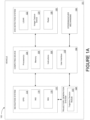
- Figure 1A illustrates a block diagram of a system 100 that includes a vehicle 101, according to an example.
- the vehicle 101 includes a computing device 102, a navigation system 112, a DVE detection system 120, a trajectory generation system 128, and steering/hover mechanisms 132.
- Other devices, systems, devices, modules, software, data stores, and the like can also be included.
- various components described with respect to Figure 1A may be integrated into a singular computing device or system, separated into further discrete components, or otherwise rearranged to achieve similar functionality to that described herein.
- various systems, devices, and mechanisms can be implemented in either a software or hardware context.
- the computing device 102 includes one or more processor(s) 104, a memory 106, instructions 108, and a user interface 110.
- the one or more processor(s) 104 is general-purpose processors or special purpose processors (e.g., digital signal processors, application specific integrated circuits, etc.).
- the one or more processor(s) 104 are configured to execute the instructions 108 (e.g., computer-readable program instructions) that are stored in the memory 106 to provide the functionality of computing device 102, and related systems and methods described herein.
- the memory 106 includes or takes the form of one or more computer-readable storage media that are read or accessed by the processor(s) 104.
- the computer-readable storage media can include volatile and/or non-volatile storage components, such as optical, magnetic, organic or other memory or disc storage, which can be integrated in whole or in part with the processor(s) 104.
- the memory 106 is considered non-transitory computer readable media.
- the memory 106 can be implemented using a single physical device (e.g., one optical, magnetic, organic or other memory or disc storage unit), while in other examples, the memory 106 can be implemented using two or more physical devices.
- the memory 106 thus is a non-transitory computer readable storage medium, and instructions 108 executable by the processor(s) 104 are stored on the memory 106.
- the instructions 108 include computer executable code, and can be executed by the processor(s) 104 to achieve functionality described herein.
- the user interface 110 includes a mouse, a keyboard, a touchscreen, a microphone, a gesture recognition system, a combination thereof, or any other means of receiving user input.
- the user interface 110 is configured to receive input from an operator (e.g., a pilot or a driver) of the vehicle 101, or a remote technician of the vehicle 101, for example. Examples described herein relate to autonomous operation of a vehicle. Accordingly, the user interface 110 may not be necessary to perform functionality described herein. Further, while the user interface is depicted as being a part of the vehicle 101, it should be understood that the user interface 110 can be integrated in a separate device that is in communication with the vehicle 101.
- the computing device 102 is communicatively coupled to the navigation system 112, the DVE detection system 120, the trajectory generation system 128, and the steering/hover mechanisms 132.
- each of these components of the vehicle 101 includes processor(s), memory, and instructions configured similarly to the one or more processor(s) 104, the memory 106, and the instructions 108 as described above, though each may include instructions executable to achieve a distinct functionality.
- these components are not depicted as being in direct communication (rather, they are shown being in communication via the computing device 102), each of these components directly communicate with one another, or operate independently without receiving communications from one another.
- the navigation system 112 includes a Global Positioning System (GPS) 114, an Inertial Navigation System (INS) 116, and an Inertial Measurement Unit (IMU) 118.
- GPS Global Positioning System
- INS Inertial Navigation System
- IMU Inertial Measurement Unit
- the navigation system 112 and/or one or more of its components is configured to determine a location, an orientation, and an altitude of the vehicle 101. More particularly, one or more of the GPS 114, the INS 116, and the IMU 118 obtains sensor data indicative of a location, orientation/attitude, and altitude (though not depicted, an altimeter, for example, may also be included) of the vehicle 101. This information, either in the form of unprocessed sensor data, or as targeted information indicative of the location, orientation, attitude, and altitude of the vehicle 101, is transmitted to the computing device 102. For example, the navigation system 112 transmits a simplified representation of the sensor data. As described below, the computing device 102 and/or one or more
- the DVE detection system 120 includes a Light Detection and Ranging (LIDAR) device 122, an image capture device 124 (e.g., a camera, a light sensor array, or another imaging device or system), and a radar device 126. Other devices may be included as well.
- the DVE detection system 120 and/or one or more of its components is configured for obtaining sensor data indicative of an environment of the vehicle 101. For example, one or more of the LIDAR device, image capture device, and the radar device 126 periodically scans an area surrounding the vehicle 101, such as an area corresponding to a planned flight path, to obtain data indicative of aspects of the environment.
- LIDAR Light Detection and Ranging
- the sensor data includes three-dimensional (3D) point cloud data, image data, or other data that indicates whether a DVE is present (e.g., detecting a number of objects exceeding an expected number).
- This information is transmitted to the computing device 102.
- the DVE detection system transmits a representation of the sensor data, a measure of confidence in the obtained data (e.g., an indication that data is noisy, or that one or more sensors have conflicting data), or an indication that a DVE has been detected.
- the computing device 102 and/or one or more additional components of the vehicle 101 may use this information in generating and selecting a trajectory for the vehicle 101.
- the trajectory generation system 128 includes a trajectory decision module 130.
- the generation system receives information from the navigation system 112 and from the computing device 102 to determine a trajectory including a flight path for the aircraft to follow.
- the trajectory generation system 128 may be a standalone computing device, or alternatively be included as part of the computing device 102, the navigation system 112, or any other component of the vehicle 101. Further details relating to the trajectory generation system 128 and the trajectory decision module 130 are described below with respect to Figure 1B .
- the steering/hover mechanisms 132 include one or more rotors, thrusters, stabilizers, ailerons, elevators, control surfaces, or other controllable operational devices of the vehicle 101.
- the computing device 102 sends control signals to the steering/hover mechanisms 132 in order to effectuate navigation, guidance, and/or control of the vehicle 101 on a determined trajectory and/or flight path.
- Figure 1B illustrates a flowchart of a trajectory decision module 130 of the vehicle 101, according to an example.
- Figure 1B shows a logical diagram describing a simplified method for determining a trajectory using the trajectory decision module 130.
- the trajectory decision module 130 can be a software program having instructions stored in memory on the trajectory generation system 128 and executable to perform functionality shown in Figure 1B .
- the flowchart representing aspects of this functionality includes blocks 134-148.
- functions include detecting a DVE. This may involve comparing sensor data obtained by one or more sensors on the vehicle 101 (e.g., one or more sensors of the DVE detection system 120) to expected data, comparing data processing outputs to an expected data processing output, comparing first sensor data from a first sensor to second sensor data from a second sensor, or failing to identify one or more objects or surfaces in the environment using sensor data. Additional details of detecting the DVE are provided below with respect to Figure 5 .
- functions include determining a phase of a route of the vehicle 101.
- the phase might be a starting phase, an ending phase, or a traveling phase.
- the starting phase may correspond to a takeoff phase of an aircraft
- the ending phase may correspond to a landing phase of the aircraft
- the traveling phase may correspond to a cruising phase of the aircraft.
- the computing device 102 may determine the phase based on one or more predetermined waypoints of the route compared to a position of the vehicle 101.
- block 136 can be performed prior to or concurrently with block 134. Other blocks in the trajectory decision module 130 are performed based on which phase is determined at block 136.
- a first segment of a trajectory along which to search for an improved navigation environment is described below with respect to Figures 2A-3E , and Figure 5 .
- functions include determining whether an improved navigation environment is detected while traveling along the first segment of the trajectory.
- improved navigation environment refers to determining a threshold increase in similarity between the sensor data and the expected data (e.g., a threshold increase in correlation), an improved data processing output (e.g., a number of detected obstacles falling below a threshold number), a threshold increase in data resolution, a threshold increase in data similarity (e.g., based on comparing data from two or more sensors), or an increased confidence in detecting an object or surface (e.g., using statistical metrics such as a confidence interval, correlation, or 1 - p-value) relative to the DVE or relative to one or more benchmarks associated with an improved navigation environment.
- the improved navigation environment is detected using sensor data from one or more sensors in DVE detection system 120.
- functions include determining a new trajectory for the vehicle 101.
- the new trajectory may start at a position at which the improved navigation environment is detected, and end at a previously defined waypoint on the route of the vehicle 101.
- the new trajectory may include an ascending hover that ends at a predetermined altitude, and which then transitions to a cruising phase of the vehicle 101.
- functions include determining a return trajectory to a starting position of the vehicle 101.
- the return trajectory may start at an end point of the first segment of the trajectory, and end at a takeoff point of the vehicle 101. The new trajectory or returning to the takeoff point serves as a second segment following the first segment of the trajectory.
- functions include determining whether an improved navigation environment is detected while traveling along the first segment of the trajectory.
- functions include following a planned trajectory.
- the first segment of the trajectory includes an end point at which the vehicle 101 determines if an improved navigation environment is detected, and the planned trajectory of block 146 may be determined at the same time (or at substantially the same time) as the first segment. If the improved navigation environment is detected, the vehicle 101 continues along the planned trajectory. The planned trajectory serves as a second segment following the first segment of the trajectory.
- functions include a providing a decision prompt of the vehicle 101.
- the decision prompt may include a prompt to switch from an autonomous mode of operation of the vehicle 101 to a manual mode of operation of the vehicle 101, a prompt to determine a second segment of the trajectory that deviates from the planned trajectory of block 146, or a prompt to follow the planned trajectory of block 146 even without detecting an improved navigation environment.
- the trajectory decision module allows for adaptive contextual control of the vehicle 101 after detecting a DVE.
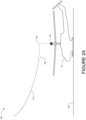
- Figure 2A illustrates the vehicle 101 in a takeoff phase 200 of a route with a clear visual environment, according to an example.
- Figure 2A shows an example scenario in which the vehicle 101 does not detect a DVE.
- the vehicle initially rests on a ground surface 202, and begins to approach a predetermined hover point 208 at which the predetermined takeoff trajectory 210 begins.
- the vehicle 101 From a takeoff point 204, the vehicle 101 follows a translation path 206 in which its position is translated to reach a hover point 208.
- the translation path 206 is depicted as including a vertical segment and a horizontal segment, it should be understood that the translation path includes more or fewer than two segments.
- the hover point 208 corresponds to a takeoff waypoint for the vehicle 101.
- the vehicle 101 rotates to align with a direction of a flight path for the takeoff phase.
- the DVE detection system 120 scans in a direction of a takeoff trajectory 210, or more generally in an environment surrounding the vehicle 101, to determine whether a DVE is detected.
- the environment does not include a DVE, so the vehicle 101 follows the takeoff trajectory 210.
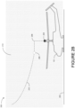
- FIG. 2B illustrates the vehicle 101 in the takeoff phase 200 of a route with a degraded visual environment 212, according to an example.
- the vehicle 101 is depicted as a helicopter, and in the example scenario depicted in Figure 2B the degraded visual environment 212 may result from dust or sand being kicked up into the air by rotors of the vehicle 101, from fog, rain, snow, or other factors that limit visibility.
- One or more sensors on vehicle 101 scan the environment while vehicle 101 is on the ground surface 202 or while the vehicle travels towards the hover point 208. In this and other example scenarios, the vehicle 101 detects the DVE. Detecting a DVE is described in further detail below with respect to Figure 5 .
- the vehicle 101 determines a first segment of a trajectory for handling the DVE, and a second segment for handling the DVE.
- the first segment and the second segment may be alterations of the translation path 206 and the takeoff trajectory 210.
- the vehicle 101 may instead follow an upward trajectory while searching for an improved navigation environment. Further details of this process are described below with respect to Figures 2C , 2D , and 2E .
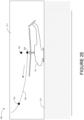
- Figure 2C illustrates the vehicle 101 following a first segment 218 of a trajectory according to an example.
- the first segment 218 of the trajectory follows a path between a first waypoint 220 and a second waypoint 222.
- the first waypoint 220 corresponds to a point at which the DVE is detected
- the second waypoint 222 corresponds to a predetermined altitude, such as a maximum hover height of the vehicle 101.
- the vehicle 101 travels upward along the trajectory to search for an improved navigation environment. While searching for the improved navigation environment, the one or more sensors on the vehicle 101 may continually scan for signs of increased visibility. Detecting an improved navigation environment is described in further detail below with respect to Figure 5 .
- Figure 2D illustrates the vehicle 101 following a second segment 224 of the trajectory, according to an example.
- Figure 2D shows the second segment 224 after failing to detect an improved navigation environment while following the first segment 218 of the trajectory.
- the vehicle 101 remains within the degraded visual environment 212 after reaching the second waypoint 222.
- the vehicle 101 determines a return trajectory that starts at the second waypoint 222, and ends at the ground surface 202.
- the vehicle 101 waits for a predetermined period of time prior to making a second attempt at searching for an improved navigation environment.
- the predetermined time is a default threshold, such as 15 minutes, or a threshold associated with a particular type of DVE.
- the vehicle 101 determines a type of DVE using the sensor data, such as by determining that the sensor data closely matches a data signature of a particular type of DVE.
- Figure 2D illustrates the vehicle 101 taking a direct path along the second segment 224 to the ground surface 202, it should be understood that other paths are possible for the second segment 224.
- the second segment 224 may lead to a last known location without a DVE.
- the vehicle 101 may rely on GPS, IMU or other data in order to navigate while ignoring sensor data used to detect the DVE, such as image data or LIDAR data.
- Figure 2E illustrates the vehicle 101 following an alternative second segment 226 of the trajectory, according to an example.
- the vehicle 101 detects an improved navigation environment 211 prior to reaching the second waypoint 222 of the first segment 218.
- the alternative second segment 226 starts at a point 228 at which the improved navigation environment 211 is detected, and ends at a predetermined waypoint 230 that is included in the route of the vehicle 101.
- predetermined waypoint 230 is associated with an end to the takeoff phase of the route.
- Figures 2A-2E show the vehicle 101 in multiple example scenarios associated with a helicopter. It should be understood that similar scenarios may exist for other types of aircraft and rotorcraft, such as a vertical take-off and landing (VTOL) aircraft and short take-off and landing aircraft (STOL). Further, it should be understood that there are alternative contexts for determining trajectories in the presence of a DVE for still other types of aircraft, such as a fixed wing aircraft, and for other types of vehicles, such as land vehicles or marine vehicles.
- VTOL vertical take-off and landing
- STOL short take-off and landing aircraft
- Figure 3A illustrates the vehicle 101 in a landing phase 300 of a route with a clear visual environment, according to an example.
- Figure 3A depicts a scenario in which the vehicle 101 does not detect a DVE.
- the vehicle 101 follows a trajectory defined by a path 302 that starts at a first waypoint 304 and ends at a second waypoint 306.
- the second waypoint 306 corresponds to a hover point at which the vehicle maneuvers to reaching a landing location 308 on the ground surface 202. Because the vehicle 101 does not detect a DVE in the scenario depicted in Figure 3A , the vehicle 101 continues to travel normally along the route during the landing phase 300.
- Figure 3B illustrates the vehicle 101 in the landing phase 300 of a route with a degraded visual environment 310, according to an example.
- the scenario depicted in Figure 3B shows the vehicle 101 having detected a remote DVE.
- Detecting the DVE in this context may include failing to detect an object or the ground surface 202 from an altitude at which such details are expected to be identifiable by one or more sensors on the vehicle 101, detecting an unexpected aspect of the environment, such as detecting more than a threshold/expected number of obstacles in the environment, or receiving a report of a DVE from another vehicle or a remote device.
- a weather report may indicate that a target landing location of the route is surrounded by heavy fog, rain, a sand storm, or other conditions associated with a DVE. Further details of determining a DVE are described below with respect to Figure 5 .
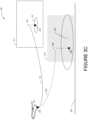
- Figure 3C illustrates the vehicle 101 determining first segment of a trajectory according to an example.
- Figure 3C depicts a scenario in which the vehicle 101 determines an alternative landing location 318 that corresponds to an area 312 with no identified DVE.
- the first segment of the trajectory is defined by a path 314 that starts at a first waypoint 304 and ends at a second waypoint 316 associated with the alternative landing location 318.
- the vehicle 101 may include a database of landing locations or have access to a database of landing locations that includes landing ratings for each landing location. For example, landing ratings indicate how many times the vehicle 101 or a plurality of vehicles have landed at a given landing location, the reliability of a ground surface at the landing location, typical wind conditions at the landing location, and additional or alternative factors. These factors are scored and weighted to form a landing rating, perhaps using a cost function or another cost-benefit calculation.
- Determining the alternative landing location 318 is part of determining a trajectory along which to search for an improved navigation environment.
- determining the first segment may include a decision prompt to an autonomous or manual operator indicating available landing locations and corresponding landing ratings, distance, time, and other considerations in order to determine whether to deviate from the route.
- the decision prompt may coincide with detecting the degraded visual environment 310, and may either include a query to an autonomous controller of the vehicle 101 (e.g., computing device 102) or a request presented on a user interface to a manual operator (e.g., the user interface 110)
- the first segment follows a trajectory towards the alternative landing location 318 or another alternative location, or the first segment follows a predetermined trajectory associated with the route (e.g., along a trajectory that follows path 302).
- Figure 3D illustrates the vehicle 101 determining a second segment 320 of the trajectory in the degraded visual environment 310, according to an example.
- Figure 3D depicts a scenario in which the vehicle 101 progresses to the landing location 308 despite detecting the degraded visual environment 310.
- determining a first segment corresponds to following a predetermined route associated with the path 302. While following the path 302, the vehicle 101 continues to scan for an improved navigation environment, such as an alternative landing location within an area 322 surrounding the landing location 308.
- the first segment diverges from the predetermined route while the vehicle 101 searches for an improved navigation environment.
- the degraded visual environment 310 has not dissipated by the time the vehicle 101 approaches the second waypoint 306 while following a first segment 324 of the trajectory.
- the vehicle 101 enters the degraded visual environment 310 responsive to one or more decision prompts, and may involve switching from an autonomous mode of operation to a manual mode of operation, or switching off or ignoring sensor data from one or more sensors (e.g., an RGB camera and/or a LIDAR device) while navigating the vehicle 101.
- the vehicle relies on GPS data, radar data, or other non-visual data rather than visual data such as RGB camera data or LIDAR data.
- the vehicle 101 After reaching an end of the first segment 324 of the trajectory at the second waypoint 306, the vehicle 101 follows a second segment 320 of the trajectory until reaching the ground surface 202. As shown in Figure 3D , the second segment 320 might not exactly correspond with the landing location 308 due to less visual information being available to the vehicle 101 while navigating in the degraded visual environment 310. For example, directly after, or nearly directly after, reaching the second waypoint 306, the vehicle descends towards the ground surface 202.
- Figure 3E illustrates the vehicle 101 determining a second segment 327 of the trajectory in a clear environment, according to an example.
- Figure 3E depicts a scenario in which the vehicle 101 follows a first segment 326 of a trajectory along the path 314 corresponding to an improved navigation environment 311. While following the first segment 326, the vehicle 101 monitors sensor data or incoming reports to confirm that the improved navigation environment 311 persists, and may re-asses the first segment 326 if a DVE is encountered. Accordingly, in this context, the vehicle 101 is considered to be "searching" for the improved navigation environment 311 at least because an environment surrounding the alternative landing location 318 might not be observable at the first waypoint 304 (shown in Figure 3C ).
- the second segment 327 of the trajectory begins at the second waypoint 316 and ends at the alternative landing location 318.
- determining a first segment and second segment of a trajectory during a landing phase 300 of a route differs depending on context and based on one or more decision prompts of the vehicle 101, allowing for adaptive trajectories during the landing phase 300.
- the vehicle 101 identifies a DVE while approaching a landing location, such as the alternative landing location 318.
- a landing location such as the alternative landing location 318.
- the vehicle 101 is a helicopter
- rotor downwash may disturb dust or sand at the landing location, thereby obscuring relevant visual cues and causing the DVE.
- the vehicle 101 selectively ignores the sensor data from one or more sensors after detecting the DVE, and continue along a predetermined trajectory, perhaps relying on other sensor data, such as GPS data, or previously determined information.
- the vehicle 101 detects the DVE while following the second segment 327, but continue towards the alternative landing location 318.
- the second segment 327 might not exactly correspond with the alternative landing location 318 due to less sensor data being available to the vehicle 101 while navigating in the DVE.
- Figure 4 illustrates a user interface 400, according to an example.
- Figure shows the user interface 400 in the context of providing a decision prompt 402 after detecting a DVE.
- the user interface includes the decision prompt 402, a map 404, a plurality of landing ratings 406 corresponding to alternative landing locations, and a representation of the DVE 408.
- Other information such as priority of landing at a target landing location of the route, fuel status, time cost of re-routing, and other factors may be presented in the user interface 400.
- This allows a manual operator of the vehicle 101 to assess the costs and benefits of following an alternative trajectory. Similar information is considered programmatically by an autonomous controller of the vehicle 101 in order to determine whether to generate and follow an alternative trajectory to a different landing location.
- decision prompt 402 relates to updating a route of a vehicle 101
- other decision prompts may be presented to an operator of the vehicle. For example, after the first segment of a trajectory ends in a DVE, a secondary prompt to switch from an autonomous mode of operation to a manual mode of operation may be presented, or a prompt to switch off or ignore certain sensor data may be presented. In this manner, multiple decision prompts may be provided to an operator to allow a robust system of handling a detected DVE.
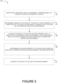
- Figure 5 illustrates a flowchart of a method 500 of controlling a vehicle in a degraded visual environment, according to an example.
- Method 500 shown in Figure 5 presents an example of a method that could be used with the vehicle 101 shown in Figure 1A , or with components of vehicle 101, such as the computing device 102 described with respect to Figure 1A .
- devices or systems may be used or configured to perform logical functions presented in Figure 5 .
- components of the devices and/or systems may be configured to perform the functions such that the components are actually configured and structured (with hardware and/or software) to enable such performance.
- components of the devices and/or systems may be arranged to be adapted to, capable of, or suited for performing the functions, such as when operated in a specific manner.
- Method 500 may include one or more operations, functions, or actions as illustrated by one or more of blocks 502-510. Although the blocks are illustrated in a sequential order, these blocks may also be performed in parallel, and/or in a different order than those described herein. Also, the various blocks may be combined into fewer blocks, divided into additional blocks, and/or removed based upon the desired implementation.
- each block or portions of each block represent a module, a segment, or a portion of program code, which includes one or more instructions executable by a processor for implementing specific logical functions or steps in the process.
- the program code may be stored on any type of computer readable medium or data storage, for example, such as a storage device including a disk or hard drive. Further, the program code can be encoded on a computer-readable storage media in a machine-readable format, or on other non-transitory media or articles of manufacture.
- the computer readable medium may include non-transitory computer readable medium or memory, for example, such as computer-readable media that stores data for short periods of time like register memory, processor cache and Random Access Memory (RAM).
- the computer readable medium may also include non-transitory media, such as secondary or persistent long term storage, like read only memory (ROM), optical or magnetic disks, compact-disc read only memory (CD-ROM), for example.
- the computer readable media may also be any other volatile or non-volatile storage systems.
- the computer readable medium may be considered a tangible computer readable storage medium, for example.
- each block or portions of each block in Figure 5 may represent circuitry that is wired to perform the specific logical functions in the process.
- Alternative implementations are included within the scope of the examples of the present disclosure in which functions may be executed out of order from that shown or discussed, including concurrent, substantially concurrent or in reverse or substantially order, depending on the functionality involved, as would be understood by those reasonably skilled in the art.
- the method 500 includes identifying a degraded visual environment 212 corresponding to a phase of a route followed by the vehicle 101.
- identifying the degraded visual environment 212 may be performed by the DVE detection system 120, as described above with respect to Figure 1A .
- the method 500 includes determining, based on the phase of the route, a first segment 218 of a trajectory of the vehicle 101 along which to search for a location with an improved navigation environment 211.
- the first segment 218 includes an upwards trajectory
- the first segment may include a trajectory towards a selected landing location.
- the method 500 includes causing the vehicle 101 to follow the first segment 218 until: (i) identifying the improved navigation environment 211, or (ii) reaching an end of the first segment 218 without identifying the improved navigation environment 211.
- this involves searching for the improved navigation environment 211 until reaching a predetermined altitude (e.g., a maximum hovering altitude of the vehicle 101).
- this involves searching for confirmation that an alternative landing location (e.g., the alternative landing location 318) corresponds to an improved navigation environment (e.g., the improved navigation environment 311).
- detecting an improved navigation environment includes comparing sensor data to one or benchmarks for the sensor data, such as comparing first sensor data from a first sensor (e.g., a LIDAR) to second sensor data from a second sensor (e.g., a radar), and confirming that the first sensor data and the second sensor data represent the environment in a similar manner (e.g., within a threshold level of variation, such as with a correlation of .8 or greater).
- detecting the improved navigation environment involves determining a change in data processing outputs using the sensor data. For example, this involves confirming that a surface (e.g., ground surface 202) or object is identifiable using sensor data, perhaps after previously failing to identify the surface or obj ect.
- determining a change in data processing outputs includes determining a change in a number of detected obstacles using the sensor data. For example, if the DVE is determined based on an excess number of obstacles are detected in the environment (e.g., a detected number of obstacles exceeding a threshold number), then a reduction in the number of detected obstacles (e.g., a reduced number that is less than the threshold number) indicates an improved navigation environment.
- determining the improves visual environment can be based on a type of DVE or a metric used for identifying the DVE. Other metrics of increased visibility relative to the DVE are possible.
- the method 500 includes determining a second segment (e.g., the alternative second segment 226) of the trajectory based on whether the improved navigation environment 211 has been identified. For example, in the takeoff phase 200, this involves determining whether the improved navigation environment 211 has been identified before reaching the predetermined altitude. In the landing phase 300, this involves determining whether to follow a planned trajectory (e.g., the planned route of block 140) or considering a decision prompt in order to determine the second segment (e.g., the second segment 327).
- a planned trajectory e.g., the planned route of block 140
- a decision prompt in order to determine the second segment (e.g., the second segment 327).
- the method 500 includes causing the vehicle to follow the second segment. Determining the first segment and the second segment in this manner allows the vehicle 101 to adaptively and reliably navigate within the degraded visual environment 212.
- identifying the degraded visual environment includes receiving sensor data obtained by one or more sensors (e.g., one or more sensors of the DVE detection system 120) on the vehicle 101, determining a difference between the sensor data and expected data, and identifying the degraded visual environment based on determining the difference between the sensor data and the expected data.
- the expected data includes a data signature for each type of sensor that indicates a clear visual environment.
- identifying the degraded visual environment includes receiving sensor data obtained by one or more sensors (e.g., one or more sensors of the DVE detection system 120) on the vehicle 101, determining a data processing output (e.g., detecting one or more obstacles using the sensor data), comparing the data processing output to an expected data processing output (e.g., a threshold number of detected obstacles, such as a 10 detected obstacles), and identifying the degraded visual environment based on comparing the data processing output to the expected data processing output. For example, if the vehicle 101 appears to be surrounded by a number of obstacles that exceeds the threshold number based on the sensor data, then a degraded visual environment can be identified.
- a data processing output e.g., detecting one or more obstacles using the sensor data
- an expected data processing output e.g., a threshold number of detected obstacles, such as a 10 detected obstacles
- the vehicle can identify the DVE based on a data processing output, and react accordingly, such as by searching for an improved navigation environment within predetermined constraints.
- the one or more sensors includes a Light Detection and Ranging (LIDAR) device, and determining the difference between the sensor data and the expected data includes determining a difference between a number of returning light pulses represented by the sensor data and an expected number of returning light pulses. For example, a threshold percentage (e.g., 75%) of returning light pulses may be used for the comparison, and a threshold deviation (e.g., more than ⁇ 10%) of returning light pulses indicates the degraded visual environment 212.
- LIDAR Light Detection and Ranging
- the one or more sensors includes a camera (e.g., an RGB camera), and determining the difference between the sensor data and the expected data includes determining a lack of variation in pixel intensities relative to the expected data. For example, a histogram of the pixel intensities may not follow an expected distribution, and instead have mostly similar pixel intensities that indicate scattered or ambient lighting associated with the degraded visual environment 212.
- identifying the degraded visual environment 212 includes receiving sensor data obtained by one or more sensors on the vehicle 101, searching for an identifiable surface (e.g., the ground surface 202) from the sensor data, and identifying the degraded visual environment based on the search. For example, this involves failing to identify the ground surface 202 from a predetermined distance (e.g., 200 feet (60 m)) may be associated with the degraded visual environment.
- a predetermined distance e.g. 200 feet (60 m)
- a histogram of pixel intensities of a camera match a histogram a given source of a DVE (e.g., dust, fog, etc.), or a distribution of detected distances from a LIDAR device match a distribution of distances of a given source of a DVE.
- the data signature comprises a noise signature associated with the one or more sensors.
- data associated with a DVE may manifest as Gaussian noise, salt-and-pepper noise, shot noise, or another type of noise signature.
- identifying the degraded visual environment 212 includes receiving an indication of an area 322 having the degraded visual environment 310, and determining that a waypoint (e.g., the second waypoint 306) associated with the first segment of the trajectory falls within the area 322.
- the indication of the area 322 may be a weather report or visibility report received from another vehicle or another computing device, such as an air traffic controller.
- identifying the degraded visual environment 212 environment includes receiving sensor data obtained by one or more sensors on the vehicle, 101 wherein the sensor data comprises first sensor data from a first sensor (e.g., an RGB camera) and second sensor data from a second sensor (e.g., a radar), and identifying the degraded visual environment based on a comparison between the first sensor data and the second sensor data.
- the second sensor data indicates an object or surface that is not indicated by the first sensor data, or the second sensor data may render into a representation of the environment that does not match a representation of the environment rendered from the first sensor data.
- the first sensor data may be associated with a first category of sensors.
- the first category of sensors may be a visual sensor that converts light rays into electronic signals and outputs a 2D pixel array representation of a measured 3D space.
- the term "visual” relates to light being readable/detectable by the sensor, and the term "light” includes the visible spectrum as well as the infrared spectrum.
- the second sensor data may be associated with a second category of sensors.
- the second category of sensors may be a non-visual sensor that does not resolve detected light into a 2D pixel array representation of a measured 3D space. This may include sound wave detectors, magnetic sensors, pressure sensors, temperature sensors, or other sensors that do not correspond to the first category of sensors.
- the first sensor data and the second sensor data may correspond to two different sensors, which provides redundancy in detecting a DVE, detecting an improved navigation environment after detecting the DVE, verifying DVE detections between the first and second sensors data, identifying failure of one of the first and second sensors based on a comparison between the first and second sensor data, or enhancing the accuracy of DVE detection using two different characteristics of the sensor data from the first and second sensors.
- sensors include an electro-optical (EO) sensor and a short wave infrared (SWIR) sensor, a synthetic aperture radar (SAR) sensor and a LIDAR sensor, a SAR sensor and an EO sensor, a SAR sensor and a SWIR sensor, two EO sensors, two LIDAR sensors.
- Some sensors have differing ability to view an environment when the vehicle 101 is in a DVE.
- a long wave infrared (LWIR) sensor have better ability to see through the DVE than a LIDAR sensor, while the LIDAR sensor has a higher resolution that the LWIR sensor, and these can be paired together when determining the second segment of the trajectory.
- LWIR sensor can be paired with an EO sensor, or with an SWIR sensor.
- different sensors having relatively high ability to view the environment during the DVE but having relatively low resolutions can be paired together.
- a SAR sensor can be paired with a LWIR sensor.
- Other combinations of sensors that provide the first sensor data and the second sensor data are possible.
- the vehicle 101 includes an aircraft and the phase of the route is a takeoff phase 200.
- determining the first segment 218 of the trajectory includes determining an upward trajectory that starts at a takeoff location and ends at a predetermined waypoint.
- determining the second segment 224 of the trajectory based on whether the improved navigation environment has been identified includes determining that the improved navigation environment has not been identified while following the first segment 218 of the trajectory, and responsive to determining that the improved navigation environment has not been identified while following the first segment 218 of the trajectory, determining a downward trajectory that starts at the predetermined waypoint and ends at the takeoff location. For example, this corresponds to the examples illustrated in Figures 2C and 2D .
- the vehicle 101 includes an aircraft and the phase of the route is a landing phase 300.
- determining the first segment of the trajectory includes determining a downward trajectory that starts at a current position of the aircraft and ends at a landing waypoint disposed above a ground surface 202.
- the vehicle 101 includes an aircraft navigating towards a landing location 308, and the phase of the route is a landing phase 300.
- the method 500 further includes determining a landing rating for the landing location 308 based on previous landings of one or more aircrafts at the landing location.
- the aircraft includes or has access to a database of landing locations and landing ratings corresponding to the landing locations, and determining the landing ratings includes retrieving a landing rating for the landing location 308.
- Determining the first segment of the trajectory can include setting an alternative landing location (e.g., the alternative landing location 318) based on (i) the landing rating being less than a threshold landing rating (e.g., less than 80 out of 100), and (ii) the degraded visual environment 310.
- determining the first segment 326 of a trajectory includes determining a trajectory that starts at a current position of the aircraft and ends at a second waypoint 316 associated with the alternative landing location 318.
- the method 500 further includes, responsive to determining the degraded visual environment, providing a prompt (e.g., the decision prompt 402) by way of a user interface 400 of the vehicle 101.
- a prompt e.g., the decision prompt 402
- the prompt relates to (i) the degraded visual environment 310, and (ii) an option to set the first segment 326 of the trajectory and the second segment 327 of the trajectory.
- the method 500 further includes, responsive to determining the degraded visual environment 310, switching from an autonomous mode of operation of the vehicle 101 to a manual mode of operation of the vehicle 101.
- the described systems and methods described herein provide functionality that enables autonomous takeoff and landing of a vehicle in a degraded visual environment. Determining segments of a trajectory of the vehicle depending on context and the degraded visual environment allows for a robust, consistent, and adaptive manner of handling different types of visual states, and provides both autonomous and manual operators ways of dynamically selecting and updating routes of the vehicle.
- a land vehicle may also encounter a DVE, and may handle its route differently depending on a current phase (e.g., a starting phase or an ending phase) of the route. Accordingly, the above-described embodiments are not limited to those involving an aircraft, but can more generally be applied to vehicles.
- system(s), device(s), and method(s) disclosed herein include a variety of components, features, and functionalities. It should be understood that the various examples of the system(s), device(s), and method(s) disclosed herein may include any of the components, features, and functionalities of any of the other examples of the system(s), device(s), and method(s) disclosed herein in any combination or any sub-combination, and all of such possibilities are intended to be within the scope of the disclosure.
Landscapes
- Engineering & Computer Science (AREA)
- Aviation & Aerospace Engineering (AREA)
- Radar, Positioning & Navigation (AREA)
- Remote Sensing (AREA)
- Physics & Mathematics (AREA)
- General Physics & Mathematics (AREA)
- Automation & Control Theory (AREA)
- Computer Networks & Wireless Communication (AREA)
- Navigation (AREA)
Description
- The present disclosure relates generally to operation of a vehicle, and more particularly, to systems and method for operating a vehicle in a degraded visual environment.
- A vehicle, such as an aircraft, may operate to travel along a predetermined route. Some contexts of operating the vehicle may rely at least in part on visual information. For example, a takeoff or landing phase of a route for an aircraft may use visual information to navigate the aircraft. A degraded visual environment may impair such navigation.
- In the context of autonomous operation of a vehicle, lacking or unreliable sensor data caused by a degraded visual environment presents difficulties. For example, a controller of the vehicle may have difficulty identifying obstacles in the environment, or orienting the vehicle relative to a surface, such as a road surface or a ground surface. Degraded visual environments likewise disorient manual operators of vehicles. Autonomous and manual operators alike may need to make different decisions for operating the vehicle in a degraded visual environment depending on an operating context of the vehicle. Existing systems and methods for operating a vehicle in a degraded visual environment may struggle to effectively control the vehicle in these different operating contexts.
- First results of LIDAR-aided helicopter approaches during NATO DVE-mitigation trials by Michael Zimmerman et al, CEAS aeronautical journal, Springer Vienna, Volume 10, , in accordance with its abstract, states "Landing a helicopter on unprepared sites can quickly become a challenging task in operational scenarios. Especially when environmental factors reduce the available visual cues for the pilot, the risk of disorientation increases. Motivated to avoid accidents in degraded visual environments (DVE), the US Army program for DVE-Mitigation (DVE-M) with NATO participation supports international efforts in the development of systems for enhanced situational awareness during DVE. A workgroup of the German Aerospace Center (DLR) and HENSOLDT Sensors GmbH participated at flight trials of the European DVE-M campaign in Manching with DLR highly modified research helicopter. The state of a system under development was presented which combines eyes-out tunnel-in-the-sky symbology (SferiAssist®) with dynamic path updates based on a laser sensor. Details of four flights during the campaign in Manching performed in February 2017 are given and discussed in terms of a technical analysis and results of pilot evaluations."
- What is needed is a system for effectively operating a vehicle in a degraded visual environment.
- There is described herein a method for controlling a vehicle in a degraded visual environment, comprising: identifying a degraded visual environment corresponding to a phase of a route followed by the vehicle; determining, based on the phase of the route, a first segment of a trajectory of the vehicle along which to search for a location with an improved navigation environment; causing the vehicle to follow the first segment until: (i) identifying the improved navigation environment, or (ii) reaching an end of the first segment without identifying the improved navigation environment; determining a second segment of the trajectory based on whether the improved navigation environment has been identified; and causing the vehicle to follow the second segment; wherein: identifying the degraded visual environment comprises: receiving sensor data obtained by one or more sensors on the vehicle; determining a difference between the sensor data and expected data; and identifying the degraded visual environment based on determining the difference between the sensor data and the expected data; and the one or more sensors comprise a Light Detection and Ranging (LIDAR) device, and determining the difference between the sensor data and the expected data comprises determining a difference between a number of returning light pulses represented by the sensor data and an expected number of returning light pulses.
- A method for controlling a vehicle in a degraded visual environment is described. The method includes identifying a degraded visual environment corresponding to a phase of a route followed by the vehicle. The method includes determining, based on the phase of the route, a first segment of a trajectory of the vehicle along which to search for a location with an improved navigation environment. The method includes causing the vehicle to follow the first segment until: (i) identifying the improved navigation environment, or (ii) reaching an end of the first segment without identifying the improved navigation environment. The method includes determining a second segment of the trajectory based on whether the improved navigation environment has been identified. The method includes causing the vehicle to follow the second segment.
- A system for controlling a vehicle in a degraded visual environment is described. The system includes a vehicle. The vehicle includes a computing device having a processor and memory storing instructions executable by the processor. The instructions are executable by the processor to identify a degraded visual environment corresponding to a phase of a route followed by the vehicle. The instructions are executable by the processor to determine, based on the phase of the route, a first segment of a trajectory of the vehicle along which to search for a location with an improved navigation environment. The instructions are executable by the processor to cause the vehicle to follow the first segment until: (i) identifying the improved navigation environment, or (ii) reaching an end of the first segment without identifying the improved navigation environment. The instructions are executable by the processor to determine a second segment of the trajectory based on whether the improved navigation environment has been identified. The instructions are executable by the processor to cause the vehicle to follow the second segment.
- A non-transitory computer readable medium is described. The non-transitory computer readable medium has stored thereon instructions, that when executed by one or more processors of a computing device, cause the computing device to perform functions. The functions include identifying a degraded visual environment corresponding to a phase of a route followed by a vehicle. The functions include determining, based on the phase of the route, a first segment of a trajectory of the vehicle along which to search for a location with an improved navigation environment. The functions include causing the vehicle to follow the first segment until: (i) identifying the improved navigation environment, or (ii) reaching an end of the first segment without identifying the improved navigation environment. The functions include determining a second segment of the trajectory based on whether the improved navigation environment has been identified. The functions include causing the vehicle to follow the second segment.
- The features, functions, and advantages that have been discussed can be achieved independently in various examples or may be combined in yet other examples. Further details of the examples can be seen with reference to the following description and drawings.
- The novel features believed characteristic of the illustrative examples are set forth in the appended claims. The illustrative examples, however, as well as a preferred mode of use, further objectives and descriptions thereof, will best be understood by reference to the following detailed description of an illustrative example of the present disclosure when read in conjunction with the accompanying drawings, wherein:
-
Figure 1A illustrates a block diagram of a system that includes a vehicle. -
Figure 1B illustrates a flowchart of a trajectory decision module of the vehicle. -
Figure 2A illustrates a vehicle in a takeoff phase of a route with a clear visual environment. -
Figure 2B illustrates the vehicle in a takeoff phase of a route with a degraded visual environment. -
Figure 2C illustrates the vehicle following a first segment of a trajectory. -
Figure 2D illustrates the vehicle following a second segment of the trajectory. -
Figure 2E illustrates the vehicle following an alternative second segment of the trajectory. -
Figure 3A illustrates a vehicle in a landing phase of a route with a clear visual environment. -
Figure 3B illustrates the vehicle in a landing phase of a route with a degraded visual environment. -
Figure 3C illustrates the vehicle determining a first segment of a trajectory. -
Figure 3D illustrates the vehicle determining a second segment of the trajectory in a degraded visual environment. -
Figure 3E illustrates the vehicle determining a second segment of the trajectory in a clear environment. -
Figure 4 illustrates a user interface. -
Figure 5 illustrates a flowchart of a method of controlling a vehicle in a degraded visual environment. - Disclosed examples will now be described more fully hereinafter with reference to the accompanying drawings, in which some, but not all of the disclosed examples are shown. Indeed, several different examples may be described and should not be construed as limited to the examples set forth herein. Rather, these examples are described so that this disclosure will be thorough and complete and will fully convey the scope of the disclosure to those skilled in the art.
- Within examples, systems and methods for operating a vehicle in a degraded visual environment (DVE) are described. As used herein, the term "degraded visual environment" refers to an environment lacking visual cues used for navigating a vehicle. For example, a DVE may result from one or more of rain, snow, fog, dust, sand, or smoke surrounding the vehicle. In DVE scenarios, a vehicle may receive sensor data that is either lacking or that misrepresents the environment or objects in the environment. Methods and systems are described that allow for automatic or manual navigation within the environment. For purposes of the following description, the terms "automatically" or "autonomously" may involve carrying out the functions programmatically based on sensor data, stored information, machine learning techniques, or the like, without user input and/or instructions. Within this context, functions may still be referred to as automatic or autonomous if they are prompted at some point by user actions.
- As used herein, the term "path" refers to a continuous set of positions between two points, such as waypoints of a route. A "trajectory" refers to a velocity (speed and direction) taken while following a path. In some instances herein, a trajectory may be referred to in terms of its path for purposes of simplicity, but it should be understood that the trajectory additionally includes a velocity or velocities for traveling along the path. A "route" refers to at least one path defined by one or more sets of waypoints. A route may include a plurality of phases, each phase corresponding to at least one waypoint.
- Within examples, a vehicle operates in different contexts that affect how to navigate within the DVE. For example, an aircraft follows a predetermined route including different phases that are defined by trajectories followed by the aircraft between various waypoints. The plurality of phases includes at least a takeoff phase, a landing phase, and a cruising phase. Depending on the phase of the route, the vehicle determines different trajectories. For example, in a takeoff phase, the vehicle may follow an upward trajectory to search for an improved navigation environment, while in a landing phase, the vehicle may follow a downward trajectory towards an alternate landing location. Accordingly, the methods and systems described herein provide an adaptive way of addressing a DVE experienced by a vehicle. In particular, examples described herein relate to determining trajectories for identifying improved visual conditions based on a context of experiencing the DVE.
- The following examples generally depict aircraft implementations, it should be understood that the same systems and methods can be applied to other types of vehicles as well, such as land vehicles or water vehicles.
- Turning now to the figures,
Figure 1A illustrates a block diagram of asystem 100 that includes avehicle 101, according to an example. Thevehicle 101 includes acomputing device 102, anavigation system 112, aDVE detection system 120, atrajectory generation system 128, and steering/hovermechanisms 132. Other devices, systems, devices, modules, software, data stores, and the like can also be included. Further, within examples, various components described with respect toFigure 1A may be integrated into a singular computing device or system, separated into further discrete components, or otherwise rearranged to achieve similar functionality to that described herein. Further, various systems, devices, and mechanisms, can be implemented in either a software or hardware context. - The
computing device 102 includes one or more processor(s) 104, amemory 106,instructions 108, and auser interface 110. The one or more processor(s) 104 is general-purpose processors or special purpose processors (e.g., digital signal processors, application specific integrated circuits, etc.). The one or more processor(s) 104 are configured to execute the instructions 108 (e.g., computer-readable program instructions) that are stored in thememory 106 to provide the functionality ofcomputing device 102, and related systems and methods described herein. - The
memory 106 includes or takes the form of one or more computer-readable storage media that are read or accessed by the processor(s) 104. The computer-readable storage media can include volatile and/or non-volatile storage components, such as optical, magnetic, organic or other memory or disc storage, which can be integrated in whole or in part with the processor(s) 104. Thememory 106 is considered non-transitory computer readable media. In some examples, thememory 106 can be implemented using a single physical device (e.g., one optical, magnetic, organic or other memory or disc storage unit), while in other examples, thememory 106 can be implemented using two or more physical devices. Thememory 106 thus is a non-transitory computer readable storage medium, andinstructions 108 executable by the processor(s) 104 are stored on thememory 106. Theinstructions 108 include computer executable code, and can be executed by the processor(s) 104 to achieve functionality described herein. - The
user interface 110 includes a mouse, a keyboard, a touchscreen, a microphone, a gesture recognition system, a combination thereof, or any other means of receiving user input. In particular, theuser interface 110 is configured to receive input from an operator (e.g., a pilot or a driver) of thevehicle 101, or a remote technician of thevehicle 101, for example. Examples described herein relate to autonomous operation of a vehicle. Accordingly, theuser interface 110 may not be necessary to perform functionality described herein. Further, while the user interface is depicted as being a part of thevehicle 101, it should be understood that theuser interface 110 can be integrated in a separate device that is in communication with thevehicle 101. - As shown in
Figure 1A , thecomputing device 102 is communicatively coupled to thenavigation system 112, theDVE detection system 120, thetrajectory generation system 128, and the steering/hovermechanisms 132. Though not depicted inFigure 1A , each of these components of thevehicle 101 includes processor(s), memory, and instructions configured similarly to the one or more processor(s) 104, thememory 106, and theinstructions 108 as described above, though each may include instructions executable to achieve a distinct functionality. Further, though these components are not depicted as being in direct communication (rather, they are shown being in communication via the computing device 102), each of these components directly communicate with one another, or operate independently without receiving communications from one another. - The
navigation system 112 includes a Global Positioning System (GPS) 114, an Inertial Navigation System (INS) 116, and an Inertial Measurement Unit (IMU) 118. Thenavigation system 112 and/or one or more of its components is configured to determine a location, an orientation, and an altitude of thevehicle 101. More particularly, one or more of theGPS 114, theINS 116, and theIMU 118 obtains sensor data indicative of a location, orientation/attitude, and altitude (though not depicted, an altimeter, for example, may also be included) of thevehicle 101. This information, either in the form of unprocessed sensor data, or as targeted information indicative of the location, orientation, attitude, and altitude of thevehicle 101, is transmitted to thecomputing device 102. For example, thenavigation system 112 transmits a simplified representation of the sensor data. As described below, thecomputing device 102 and/or one or more additional components of thevehicle 101 use this information in generating and selecting a flight path or trajectory for thevehicle 101. - The
DVE detection system 120 includes a Light Detection and Ranging (LIDAR)device 122, an image capture device 124 (e.g., a camera, a light sensor array, or another imaging device or system), and aradar device 126. Other devices may be included as well. TheDVE detection system 120 and/or one or more of its components, is configured for obtaining sensor data indicative of an environment of thevehicle 101. For example, one or more of the LIDAR device, image capture device, and theradar device 126 periodically scans an area surrounding thevehicle 101, such as an area corresponding to a planned flight path, to obtain data indicative of aspects of the environment. The sensor data includes three-dimensional (3D) point cloud data, image data, or other data that indicates whether a DVE is present (e.g., detecting a number of objects exceeding an expected number). This information, either in the form of unprocessed sensor data, or as targeted information indicative of the environment surrounding thevehicle 101, is transmitted to thecomputing device 102. For example, the DVE detection system transmits a representation of the sensor data, a measure of confidence in the obtained data (e.g., an indication that data is noisy, or that one or more sensors have conflicting data), or an indication that a DVE has been detected. As described below, thecomputing device 102 and/or one or more additional components of thevehicle 101 may use this information in generating and selecting a trajectory for thevehicle 101. - The
trajectory generation system 128 includes atrajectory decision module 130. The generation system receives information from thenavigation system 112 and from thecomputing device 102 to determine a trajectory including a flight path for the aircraft to follow. Thetrajectory generation system 128 may be a standalone computing device, or alternatively be included as part of thecomputing device 102, thenavigation system 112, or any other component of thevehicle 101. Further details relating to thetrajectory generation system 128 and thetrajectory decision module 130 are described below with respect toFigure 1B . - The steering/hover
mechanisms 132 include one or more rotors, thrusters, stabilizers, ailerons, elevators, control surfaces, or other controllable operational devices of thevehicle 101. Thecomputing device 102 sends control signals to the steering/hovermechanisms 132 in order to effectuate navigation, guidance, and/or control of thevehicle 101 on a determined trajectory and/or flight path. -
Figure 1B illustrates a flowchart of atrajectory decision module 130 of thevehicle 101, according to an example. In particular,Figure 1B shows a logical diagram describing a simplified method for determining a trajectory using thetrajectory decision module 130. Thetrajectory decision module 130 can be a software program having instructions stored in memory on thetrajectory generation system 128 and executable to perform functionality shown inFigure 1B . The flowchart representing aspects of this functionality includes blocks 134-148. - At
block 134, functions include detecting a DVE. This may involve comparing sensor data obtained by one or more sensors on the vehicle 101 (e.g., one or more sensors of the DVE detection system 120) to expected data, comparing data processing outputs to an expected data processing output, comparing first sensor data from a first sensor to second sensor data from a second sensor, or failing to identify one or more objects or surfaces in the environment using sensor data. Additional details of detecting the DVE are provided below with respect toFigure 5 . - At
block 136, functions include determining a phase of a route of thevehicle 101. The phase might be a starting phase, an ending phase, or a traveling phase. For example, the starting phase may correspond to a takeoff phase of an aircraft, the ending phase may correspond to a landing phase of the aircraft, and the traveling phase may correspond to a cruising phase of the aircraft. Within examples, thecomputing device 102 may determine the phase based on one or more predetermined waypoints of the route compared to a position of thevehicle 101. Within examples, block 136 can be performed prior to or concurrently withblock 134. Other blocks in thetrajectory decision module 130 are performed based on which phase is determined atblock 136. - Depending on the determined phase of the route of the
vehicle 101, a first segment of a trajectory along which to search for an improved navigation environment. Further details of determining the first segment of the trajectory are described below with respect toFigures 2A-3E , andFigure 5 . - In the context of a takeoff of the
vehicle 101, atblock 138, functions include determining whether an improved navigation environment is detected while traveling along the first segment of the trajectory. As used herein, the term "improved navigation environment" refers to determining a threshold increase in similarity between the sensor data and the expected data (e.g., a threshold increase in correlation), an improved data processing output (e.g., a number of detected obstacles falling below a threshold number), a threshold increase in data resolution, a threshold increase in data similarity (e.g., based on comparing data from two or more sensors), or an increased confidence in detecting an object or surface (e.g., using statistical metrics such as a confidence interval, correlation, or 1 - p-value) relative to the DVE or relative to one or more benchmarks associated with an improved navigation environment. The improved navigation environment is detected using sensor data from one or more sensors inDVE detection system 120. Responsive to detecting an improved navigation environment, atblock 140, functions include determining a new trajectory for thevehicle 101. For example, the new trajectory may start at a position at which the improved navigation environment is detected, and end at a previously defined waypoint on the route of thevehicle 101. In other examples, the new trajectory may include an ascending hover that ends at a predetermined altitude, and which then transitions to a cruising phase of thevehicle 101. Responsive to not detecting the improved navigation environment, atblock 142, functions include determining a return trajectory to a starting position of thevehicle 101. For example, the return trajectory may start at an end point of the first segment of the trajectory, and end at a takeoff point of thevehicle 101. The new trajectory or returning to the takeoff point serves as a second segment following the first segment of the trajectory. - In the context of landing the
vehicle 101, atblock 144, functions include determining whether an improved navigation environment is detected while traveling along the first segment of the trajectory. Responsive to detecting an improved navigation environment, atblock 146, functions include following a planned trajectory. For example, the first segment of the trajectory includes an end point at which thevehicle 101 determines if an improved navigation environment is detected, and the planned trajectory ofblock 146 may be determined at the same time (or at substantially the same time) as the first segment. If the improved navigation environment is detected, thevehicle 101 continues along the planned trajectory. The planned trajectory serves as a second segment following the first segment of the trajectory. Responsive to not detecting the improved navigation environment, atblock 148, functions include a providing a decision prompt of thevehicle 101. For example, the decision prompt may include a prompt to switch from an autonomous mode of operation of thevehicle 101 to a manual mode of operation of thevehicle 101, a prompt to determine a second segment of the trajectory that deviates from the planned trajectory ofblock 146, or a prompt to follow the planned trajectory ofblock 146 even without detecting an improved navigation environment. In this manner, the trajectory decision module allows for adaptive contextual control of thevehicle 101 after detecting a DVE. -
Figure 2A illustrates thevehicle 101 in atakeoff phase 200 of a route with a clear visual environment, according to an example. In particular,Figure 2A shows an example scenario in which thevehicle 101 does not detect a DVE. In thetakeoff phase 200, the vehicle initially rests on aground surface 202, and begins to approach a predetermined hoverpoint 208 at which thepredetermined takeoff trajectory 210 begins. From atakeoff point 204, thevehicle 101 follows atranslation path 206 in which its position is translated to reach a hoverpoint 208. Though thetranslation path 206 is depicted as including a vertical segment and a horizontal segment, it should be understood that the translation path includes more or fewer than two segments. The hoverpoint 208 corresponds to a takeoff waypoint for thevehicle 101. At or before the hoverpoint 208, thevehicle 101 rotates to align with a direction of a flight path for the takeoff phase. At or before the hover point, theDVE detection system 120 scans in a direction of atakeoff trajectory 210, or more generally in an environment surrounding thevehicle 101, to determine whether a DVE is detected. In some examples, including the example depicted inFigure 2A , the environment does not include a DVE, so thevehicle 101 follows thetakeoff trajectory 210. -
Figure 2B illustrates thevehicle 101 in thetakeoff phase 200 of a route with a degradedvisual environment 212, according to an example. Thevehicle 101 is depicted as a helicopter, and in the example scenario depicted inFigure 2B the degradedvisual environment 212 may result from dust or sand being kicked up into the air by rotors of thevehicle 101, from fog, rain, snow, or other factors that limit visibility. One or more sensors onvehicle 101 scan the environment whilevehicle 101 is on theground surface 202 or while the vehicle travels towards the hoverpoint 208. In this and other example scenarios, thevehicle 101 detects the DVE. Detecting a DVE is described in further detail below with respect toFigure 5 . - Responsive to detecting the DVE, the vehicle 101 (e.g.,
trajectory generation system 128 of vehicle 101) determines a first segment of a trajectory for handling the DVE, and a second segment for handling the DVE. The first segment and the second segment may be alterations of thetranslation path 206 and thetakeoff trajectory 210. For example, rather than approaching the hoverpoint 208 using thetranslation path 206, thevehicle 101 may instead follow an upward trajectory while searching for an improved navigation environment. Further details of this process are described below with respect toFigures 2C ,2D , and2E . -
Figure 2C illustrates thevehicle 101 following afirst segment 218 of a trajectory according to an example. Thefirst segment 218 of the trajectory follows a path between afirst waypoint 220 and asecond waypoint 222. Thefirst waypoint 220 corresponds to a point at which the DVE is detected, and thesecond waypoint 222 corresponds to a predetermined altitude, such as a maximum hover height of thevehicle 101. As shown inFigure 2C , thevehicle 101 travels upward along the trajectory to search for an improved navigation environment. While searching for the improved navigation environment, the one or more sensors on thevehicle 101 may continually scan for signs of increased visibility. Detecting an improved navigation environment is described in further detail below with respect toFigure 5 . -
Figure 2D illustrates thevehicle 101 following asecond segment 224 of the trajectory, according to an example. In particular,Figure 2D shows thesecond segment 224 after failing to detect an improved navigation environment while following thefirst segment 218 of the trajectory. As shown inFigure 2D , thevehicle 101 remains within the degradedvisual environment 212 after reaching thesecond waypoint 222. After reaching thesecond waypoint 222 of thefirst segment 218, thevehicle 101 determines a return trajectory that starts at thesecond waypoint 222, and ends at theground surface 202. Thevehicle 101 waits for a predetermined period of time prior to making a second attempt at searching for an improved navigation environment. For example, the predetermined time is a default threshold, such as 15 minutes, or a threshold associated with a particular type of DVE. For example, if the DVE is determined to be associated with sand or dust, the threshold may be 2 minutes, and if the DVE is determined to be associated with snow or fog, the threshold may be longer. Other thresholds can be used for different types of DVEs. In these examples, thevehicle 101 also determines a type of DVE using the sensor data, such as by determining that the sensor data closely matches a data signature of a particular type of DVE. - Though
Figure 2D illustrates thevehicle 101 taking a direct path along thesecond segment 224 to theground surface 202, it should be understood that other paths are possible for thesecond segment 224. For example, thesecond segment 224 may lead to a last known location without a DVE. In these examples, thevehicle 101 may rely on GPS, IMU or other data in order to navigate while ignoring sensor data used to detect the DVE, such as image data or LIDAR data. -
Figure 2E illustrates thevehicle 101 following an alternativesecond segment 226 of the trajectory, according to an example. In some examples, including the example scenario depicted inFigure 2E , thevehicle 101 detects animproved navigation environment 211 prior to reaching thesecond waypoint 222 of thefirst segment 218. The alternativesecond segment 226 starts at apoint 228 at which theimproved navigation environment 211 is detected, and ends at apredetermined waypoint 230 that is included in the route of thevehicle 101. For example,predetermined waypoint 230 is associated with an end to the takeoff phase of the route. -
Figures 2A-2E show thevehicle 101 in multiple example scenarios associated with a helicopter. It should be understood that similar scenarios may exist for other types of aircraft and rotorcraft, such as a vertical take-off and landing (VTOL) aircraft and short take-off and landing aircraft (STOL). Further, it should be understood that there are alternative contexts for determining trajectories in the presence of a DVE for still other types of aircraft, such as a fixed wing aircraft, and for other types of vehicles, such as land vehicles or marine vehicles. -
Figure 3A illustrates thevehicle 101 in alanding phase 300 of a route with a clear visual environment, according to an example. In particular,Figure 3A depicts a scenario in which thevehicle 101 does not detect a DVE. In thelanding phase 300, thevehicle 101 follows a trajectory defined by apath 302 that starts at afirst waypoint 304 and ends at asecond waypoint 306. Thesecond waypoint 306 corresponds to a hover point at which the vehicle maneuvers to reaching alanding location 308 on theground surface 202. Because thevehicle 101 does not detect a DVE in the scenario depicted inFigure 3A , thevehicle 101 continues to travel normally along the route during thelanding phase 300. -
Figure 3B illustrates thevehicle 101 in thelanding phase 300 of a route with a degradedvisual environment 310, according to an example. In particular, the scenario depicted inFigure 3B shows thevehicle 101 having detected a remote DVE. Detecting the DVE in this context may include failing to detect an object or theground surface 202 from an altitude at which such details are expected to be identifiable by one or more sensors on thevehicle 101, detecting an unexpected aspect of the environment, such as detecting more than a threshold/expected number of obstacles in the environment, or receiving a report of a DVE from another vehicle or a remote device. For example, a weather report may indicate that a target landing location of the route is surrounded by heavy fog, rain, a sand storm, or other conditions associated with a DVE. Further details of determining a DVE are described below with respect toFigure 5 . -
Figure 3C illustrates thevehicle 101 determining first segment of a trajectory according to an example. In particular,Figure 3C depicts a scenario in which thevehicle 101 determines analternative landing location 318 that corresponds to anarea 312 with no identified DVE. The first segment of the trajectory is defined by apath 314 that starts at afirst waypoint 304 and ends at asecond waypoint 316 associated with thealternative landing location 318. Thevehicle 101 may include a database of landing locations or have access to a database of landing locations that includes landing ratings for each landing location. For example, landing ratings indicate how many times thevehicle 101 or a plurality of vehicles have landed at a given landing location, the reliability of a ground surface at the landing location, typical wind conditions at the landing location, and additional or alternative factors. These factors are scored and weighted to form a landing rating, perhaps using a cost function or another cost-benefit calculation. - Determining the
alternative landing location 318 is part of determining a trajectory along which to search for an improved navigation environment. For example, in thelanding phase 300, determining the first segment may include a decision prompt to an autonomous or manual operator indicating available landing locations and corresponding landing ratings, distance, time, and other considerations in order to determine whether to deviate from the route. The decision prompt may coincide with detecting the degradedvisual environment 310, and may either include a query to an autonomous controller of the vehicle 101 (e.g., computing device 102) or a request presented on a user interface to a manual operator (e.g., the user interface 110) In view of these considerations, the first segment follows a trajectory towards thealternative landing location 318 or another alternative location, or the first segment follows a predetermined trajectory associated with the route (e.g., along a trajectory that follows path 302). -
Figure 3D illustrates thevehicle 101 determining asecond segment 320 of the trajectory in the degradedvisual environment 310, according to an example. In particular,Figure 3D depicts a scenario in which thevehicle 101 progresses to thelanding location 308 despite detecting the degradedvisual environment 310. In this context, determining a first segment corresponds to following a predetermined route associated with thepath 302. While following thepath 302, thevehicle 101 continues to scan for an improved navigation environment, such as an alternative landing location within anarea 322 surrounding thelanding location 308. In some examples, the first segment diverges from the predetermined route while thevehicle 101 searches for an improved navigation environment. - In the scenario depicted in
Figure 3D , the degradedvisual environment 310 has not dissipated by the time thevehicle 101 approaches thesecond waypoint 306 while following afirst segment 324 of the trajectory. In this scenario, thevehicle 101 enters the degradedvisual environment 310 responsive to one or more decision prompts, and may involve switching from an autonomous mode of operation to a manual mode of operation, or switching off or ignoring sensor data from one or more sensors (e.g., an RGB camera and/or a LIDAR device) while navigating thevehicle 101. For example, within the degradedvisual environment 310, the vehicle relies on GPS data, radar data, or other non-visual data rather than visual data such as RGB camera data or LIDAR data. - After reaching an end of the
first segment 324 of the trajectory at thesecond waypoint 306, thevehicle 101 follows asecond segment 320 of the trajectory until reaching theground surface 202. As shown inFigure 3D , thesecond segment 320 might not exactly correspond with thelanding location 308 due to less visual information being available to thevehicle 101 while navigating in the degradedvisual environment 310. For example, directly after, or nearly directly after, reaching thesecond waypoint 306, the vehicle descends towards theground surface 202. -
Figure 3E illustrates thevehicle 101 determining asecond segment 327 of the trajectory in a clear environment, according to an example. In particular,Figure 3E depicts a scenario in which thevehicle 101 follows afirst segment 326 of a trajectory along thepath 314 corresponding to animproved navigation environment 311. While following thefirst segment 326, thevehicle 101 monitors sensor data or incoming reports to confirm that theimproved navigation environment 311 persists, and may re-asses thefirst segment 326 if a DVE is encountered. Accordingly, in this context, thevehicle 101 is considered to be "searching" for theimproved navigation environment 311 at least because an environment surrounding thealternative landing location 318 might not be observable at the first waypoint 304 (shown inFigure 3C ). As shown inFigure 3E , thesecond segment 327 of the trajectory begins at thesecond waypoint 316 and ends at thealternative landing location 318. In this manner, determining a first segment and second segment of a trajectory during alanding phase 300 of a route differs depending on context and based on one or more decision prompts of thevehicle 101, allowing for adaptive trajectories during thelanding phase 300. - In alternative examples, the
vehicle 101 identifies a DVE while approaching a landing location, such as thealternative landing location 318. For example, in examples where thevehicle 101 is a helicopter, rotor downwash may disturb dust or sand at the landing location, thereby obscuring relevant visual cues and causing the DVE. In these examples, after detecting the DVE, thevehicle 101 selectively ignores the sensor data from one or more sensors after detecting the DVE, and continue along a predetermined trajectory, perhaps relying on other sensor data, such as GPS data, or previously determined information. For example, inFigure 3E , thevehicle 101 detects the DVE while following thesecond segment 327, but continue towards thealternative landing location 318. As in the example inFigure 3D , thesecond segment 327 might not exactly correspond with thealternative landing location 318 due to less sensor data being available to thevehicle 101 while navigating in the DVE. -
Figure 4 illustrates auser interface 400, according to an example. In particular, Figure shows theuser interface 400 in the context of providing adecision prompt 402 after detecting a DVE. In this scenario, the user interface includes thedecision prompt 402, amap 404, a plurality oflanding ratings 406 corresponding to alternative landing locations, and a representation of theDVE 408. Other information, such as priority of landing at a target landing location of the route, fuel status, time cost of re-routing, and other factors may be presented in theuser interface 400. This allows a manual operator of thevehicle 101 to assess the costs and benefits of following an alternative trajectory. Similar information is considered programmatically by an autonomous controller of thevehicle 101 in order to determine whether to generate and follow an alternative trajectory to a different landing location. - Though the
decision prompt 402 relates to updating a route of avehicle 101, other decision prompts may be presented to an operator of the vehicle. For example, after the first segment of a trajectory ends in a DVE, a secondary prompt to switch from an autonomous mode of operation to a manual mode of operation may be presented, or a prompt to switch off or ignore certain sensor data may be presented. In this manner, multiple decision prompts may be provided to an operator to allow a robust system of handling a detected DVE. -
Figure 5 illustrates a flowchart of amethod 500 of controlling a vehicle in a degraded visual environment, according to an example.Method 500 shown inFigure 5 presents an example of a method that could be used with thevehicle 101 shown inFigure 1A , or with components ofvehicle 101, such as thecomputing device 102 described with respect toFigure 1A . Further, devices or systems may be used or configured to perform logical functions presented inFigure 5 . In some instances, components of the devices and/or systems may be configured to perform the functions such that the components are actually configured and structured (with hardware and/or software) to enable such performance. In other examples, components of the devices and/or systems may be arranged to be adapted to, capable of, or suited for performing the functions, such as when operated in a specific manner.Method 500 may include one or more operations, functions, or actions as illustrated by one or more of blocks 502-510. Although the blocks are illustrated in a sequential order, these blocks may also be performed in parallel, and/or in a different order than those described herein. Also, the various blocks may be combined into fewer blocks, divided into additional blocks, and/or removed based upon the desired implementation. - It should be understood that for this and other processes and methods disclosed herein, flowcharts show functionality and operation of one possible examples. In this regard, each block or portions of each block represent a module, a segment, or a portion of program code, which includes one or more instructions executable by a processor for implementing specific logical functions or steps in the process. The program code may be stored on any type of computer readable medium or data storage, for example, such as a storage device including a disk or hard drive. Further, the program code can be encoded on a computer-readable storage media in a machine-readable format, or on other non-transitory media or articles of manufacture. The computer readable medium may include non-transitory computer readable medium or memory, for example, such as computer-readable media that stores data for short periods of time like register memory, processor cache and Random Access Memory (RAM). The computer readable medium may also include non-transitory media, such as secondary or persistent long term storage, like read only memory (ROM), optical or magnetic disks, compact-disc read only memory (CD-ROM), for example. The computer readable media may also be any other volatile or non-volatile storage systems. The computer readable medium may be considered a tangible computer readable storage medium, for example.
- In addition, each block or portions of each block in
Figure 5 , and within other processes and methods disclosed herein, may represent circuitry that is wired to perform the specific logical functions in the process. Alternative implementations are included within the scope of the examples of the present disclosure in which functions may be executed out of order from that shown or discussed, including concurrent, substantially concurrent or in reverse or substantially order, depending on the functionality involved, as would be understood by those reasonably skilled in the art. - At
block 502, themethod 500 includes identifying a degradedvisual environment 212 corresponding to a phase of a route followed by thevehicle 101. For example, identifying the degradedvisual environment 212 may be performed by theDVE detection system 120, as described above with respect toFigure 1A . - At
block 504, themethod 500 includes determining, based on the phase of the route, afirst segment 218 of a trajectory of thevehicle 101 along which to search for a location with animproved navigation environment 211. For example, in atakeoff phase 200, thefirst segment 218 includes an upwards trajectory, and in alanding phase 300, the first segment may include a trajectory towards a selected landing location. - At
block 506, themethod 500 includes causing thevehicle 101 to follow thefirst segment 218 until: (i) identifying theimproved navigation environment 211, or (ii) reaching an end of thefirst segment 218 without identifying theimproved navigation environment 211. In thetakeoff phase 200, this involves searching for theimproved navigation environment 211 until reaching a predetermined altitude (e.g., a maximum hovering altitude of the vehicle 101). In thelanding phase 300, this involves searching for confirmation that an alternative landing location (e.g., the alternative landing location 318) corresponds to an improved navigation environment (e.g., the improved navigation environment 311). - Within examples, detecting an improved navigation environment includes comparing sensor data to one or benchmarks for the sensor data, such as comparing first sensor data from a first sensor (e.g., a LIDAR) to second sensor data from a second sensor (e.g., a radar), and confirming that the first sensor data and the second sensor data represent the environment in a similar manner (e.g., within a threshold level of variation, such as with a correlation of .8 or greater). In further examples, detecting the improved navigation environment involves determining a change in data processing outputs using the sensor data. For example, this involves confirming that a surface (e.g., ground surface 202) or object is identifiable using sensor data, perhaps after previously failing to identify the surface or obj ect. In other examples, determining a change in data processing outputs includes determining a change in a number of detected obstacles using the sensor data. For example, if the DVE is determined based on an excess number of obstacles are detected in the environment (e.g., a detected number of obstacles exceeding a threshold number), then a reduction in the number of detected obstacles (e.g., a reduced number that is less than the threshold number) indicates an improved navigation environment. Within examples, determining the improves visual environment can be based on a type of DVE or a metric used for identifying the DVE. Other metrics of increased visibility relative to the DVE are possible.
- At
block 508, themethod 500 includes determining a second segment (e.g., the alternative second segment 226) of the trajectory based on whether theimproved navigation environment 211 has been identified. For example, in thetakeoff phase 200, this involves determining whether theimproved navigation environment 211 has been identified before reaching the predetermined altitude. In thelanding phase 300, this involves determining whether to follow a planned trajectory (e.g., the planned route of block 140) or considering a decision prompt in order to determine the second segment (e.g., the second segment 327). - At
block 510, themethod 500 includes causing the vehicle to follow the second segment. Determining the first segment and the second segment in this manner allows thevehicle 101 to adaptively and reliably navigate within the degradedvisual environment 212. - Within examples, identifying the degraded visual environment includes receiving sensor data obtained by one or more sensors (e.g., one or more sensors of the DVE detection system 120) on the
vehicle 101, determining a difference between the sensor data and expected data, and identifying the degraded visual environment based on determining the difference between the sensor data and the expected data. For example, the expected data includes a data signature for each type of sensor that indicates a clear visual environment. - Within examples, identifying the degraded visual environment includes receiving sensor data obtained by one or more sensors (e.g., one or more sensors of the DVE detection system 120) on the
vehicle 101, determining a data processing output (e.g., detecting one or more obstacles using the sensor data), comparing the data processing output to an expected data processing output (e.g., a threshold number of detected obstacles, such as a 10 detected obstacles), and identifying the degraded visual environment based on comparing the data processing output to the expected data processing output. For example, if thevehicle 101 appears to be surrounded by a number of obstacles that exceeds the threshold number based on the sensor data, then a degraded visual environment can be identified. These steps reveal a degraded visual environment because some types of DVEs can cause visual sensors to provide data that appears to show many obstacles in the environment that are not actually present in the environment. Rather than allowing falsely detected obstacles to impact navigation of thevehicle 101, the vehicle can identify the DVE based on a data processing output, and react accordingly, such as by searching for an improved navigation environment within predetermined constraints. - Within examples, the one or more sensors includes a Light Detection and Ranging (LIDAR) device, and determining the difference between the sensor data and the expected data includes determining a difference between a number of returning light pulses represented by the sensor data and an expected number of returning light pulses. For example, a threshold percentage (e.g., 75%) of returning light pulses may be used for the comparison, and a threshold deviation (e.g., more than ± 10%) of returning light pulses indicates the degraded
visual environment 212. - Within examples, the one or more sensors includes a camera (e.g., an RGB camera), and determining the difference between the sensor data and the expected data includes determining a lack of variation in pixel intensities relative to the expected data. For example, a histogram of the pixel intensities may not follow an expected distribution, and instead have mostly similar pixel intensities that indicate scattered or ambient lighting associated with the degraded
visual environment 212. - Within examples, identifying the degraded
visual environment 212 includes receiving sensor data obtained by one or more sensors on thevehicle 101, searching for an identifiable surface (e.g., the ground surface 202) from the sensor data, and identifying the degraded visual environment based on the search. For example, this involves failing to identify theground surface 202 from a predetermined distance (e.g., 200 feet (60 m)) may be associated with the degraded visual environment. - Within examples receiving sensor data obtained by one or more sensors on the
vehicle 101, and identifying the degradedvisual environment 212 based on determining that the sensor data matches a data signature corresponding to a type of degraded visual environment. For example, a histogram of pixel intensities of a camera match a histogram a given source of a DVE (e.g., dust, fog, etc.), or a distribution of detected distances from a LIDAR device match a distribution of distances of a given source of a DVE. Within examples, the data signature comprises a noise signature associated with the one or more sensors. For example, data associated with a DVE may manifest as Gaussian noise, salt-and-pepper noise, shot noise, or another type of noise signature. - Within examples, identifying the degraded
visual environment 212 includes receiving an indication of anarea 322 having the degradedvisual environment 310, and determining that a waypoint (e.g., the second waypoint 306) associated with the first segment of the trajectory falls within thearea 322. For example, the indication of thearea 322 may be a weather report or visibility report received from another vehicle or another computing device, such as an air traffic controller. - Within examples, identifying the degraded
visual environment 212 environment includes receiving sensor data obtained by one or more sensors on the vehicle, 101 wherein the sensor data comprises first sensor data from a first sensor (e.g., an RGB camera) and second sensor data from a second sensor (e.g., a radar), and identifying the degraded visual environment based on a comparison between the first sensor data and the second sensor data. For example, the second sensor data indicates an object or surface that is not indicated by the first sensor data, or the second sensor data may render into a representation of the environment that does not match a representation of the environment rendered from the first sensor data. - Within examples, the first sensor data may be associated with a first category of sensors. For example the first category of sensors may be a visual sensor that converts light rays into electronic signals and outputs a 2D pixel array representation of a measured 3D space. In this context, the term "visual" relates to light being readable/detectable by the sensor, and the term "light" includes the visible spectrum as well as the infrared spectrum. Further, the second sensor data may be associated with a second category of sensors. The second category of sensors may be a non-visual sensor that does not resolve detected light into a 2D pixel array representation of a measured 3D space. This may include sound wave detectors, magnetic sensors, pressure sensors, temperature sensors, or other sensors that do not correspond to the first category of sensors. In other examples, the first sensor data and the second sensor data may correspond to two different sensors, which provides redundancy in detecting a DVE, detecting an improved navigation environment after detecting the DVE, verifying DVE detections between the first and second sensors data, identifying failure of one of the first and second sensors based on a comparison between the first and second sensor data, or enhancing the accuracy of DVE detection using two different characteristics of the sensor data from the first and second sensors. Some examples of combinations of sensors include an electro-optical (EO) sensor and a short wave infrared (SWIR) sensor, a synthetic aperture radar (SAR) sensor and a LIDAR sensor, a SAR sensor and an EO sensor, a SAR sensor and a SWIR sensor, two EO sensors, two LIDAR sensors. Some sensors have differing ability to view an environment when the
vehicle 101 is in a DVE. For example, a long wave infrared (LWIR) sensor have better ability to see through the DVE than a LIDAR sensor, while the LIDAR sensor has a higher resolution that the LWIR sensor, and these can be paired together when determining the second segment of the trajectory. Similarly, a LWIR sensor can be paired with an EO sensor, or with an SWIR sensor. Still further, different sensors having relatively high ability to view the environment during the DVE but having relatively low resolutions can be paired together. For example, a SAR sensor can be paired with a LWIR sensor. Other combinations of sensors that provide the first sensor data and the second sensor data are possible. - Within examples, the
vehicle 101 includes an aircraft and the phase of the route is atakeoff phase 200. Within these examples, determining thefirst segment 218 of the trajectory includes determining an upward trajectory that starts at a takeoff location and ends at a predetermined waypoint. Within these examples, determining thesecond segment 224 of the trajectory based on whether the improved navigation environment has been identified includes determining that the improved navigation environment has not been identified while following thefirst segment 218 of the trajectory, and responsive to determining that the improved navigation environment has not been identified while following thefirst segment 218 of the trajectory, determining a downward trajectory that starts at the predetermined waypoint and ends at the takeoff location. For example, this corresponds to the examples illustrated inFigures 2C and2D . - Within examples, the
vehicle 101 includes an aircraft and the phase of the route is alanding phase 300. In these examples, determining the first segment of the trajectory includes determining a downward trajectory that starts at a current position of the aircraft and ends at a landing waypoint disposed above aground surface 202. - Within examples, the
vehicle 101 includes an aircraft navigating towards a landinglocation 308, and the phase of the route is alanding phase 300. In these examples, themethod 500 further includes determining a landing rating for thelanding location 308 based on previous landings of one or more aircrafts at the landing location. For example the aircraft includes or has access to a database of landing locations and landing ratings corresponding to the landing locations, and determining the landing ratings includes retrieving a landing rating for thelanding location 308. Determining the first segment of the trajectory can include setting an alternative landing location (e.g., the alternative landing location 318) based on (i) the landing rating being less than a threshold landing rating (e.g., less than 80 out of 100), and (ii) the degradedvisual environment 310. In these examples, determining thefirst segment 326 of a trajectory includes determining a trajectory that starts at a current position of the aircraft and ends at asecond waypoint 316 associated with thealternative landing location 318. - Within examples, the
method 500 further includes, responsive to determining the degraded visual environment, providing a prompt (e.g., the decision prompt 402) by way of auser interface 400 of thevehicle 101. In these examples, the prompt relates to (i) the degradedvisual environment 310, and (ii) an option to set thefirst segment 326 of the trajectory and thesecond segment 327 of the trajectory. - Within examples, the
method 500 further includes, responsive to determining the degradedvisual environment 310, switching from an autonomous mode of operation of thevehicle 101 to a manual mode of operation of thevehicle 101. - The described systems and methods described herein provide functionality that enables autonomous takeoff and landing of a vehicle in a degraded visual environment. Determining segments of a trajectory of the vehicle depending on context and the degraded visual environment allows for a robust, consistent, and adaptive manner of handling different types of visual states, and provides both autonomous and manual operators ways of dynamically selecting and updating routes of the vehicle.
- Though the contexts of operating vehicles provided herein generally depict or describe an aircraft, such as a helicopter, it should be understood that similar contexts may arise for other types of vehicles. For example, a land vehicle may also encounter a DVE, and may handle its route differently depending on a current phase (e.g., a starting phase or an ending phase) of the route. Accordingly, the above-described embodiments are not limited to those involving an aircraft, but can more generally be applied to vehicles.
- By the term "substantially," "similarity," and "about" used herein, it is meant that the recited characteristic, parameter, or value need not be achieved exactly, but that deviations or variations, including for example, tolerances, measurement error, measurement accuracy limitations and other factors known to skill in the art, may occur in amounts that do not preclude the effect the characteristic was intended to provide.
- Different examples of the system(s), device(s), and method(s) disclosed herein include a variety of components, features, and functionalities. It should be understood that the various examples of the system(s), device(s), and method(s) disclosed herein may include any of the components, features, and functionalities of any of the other examples of the system(s), device(s), and method(s) disclosed herein in any combination or any sub-combination, and all of such possibilities are intended to be within the scope of the disclosure.
- The description of the different advantageous arrangements has been presented for purposes of illustration and description, and is not intended to be exhaustive or limited to the examples in the form disclosed. Many modifications and variations will be apparent to those of ordinary skill in the art. Further, different advantageous examples may describe different advantages as compared to other advantageous examples. The example or examples selected are chosen and described in order to best explain the principles of the examples, the practical application, and to enable others of ordinary skill in the art to understand the disclosure for various examples with various modifications as are suited to the particular use contemplated.
Claims (15)
- A method (500) for controlling a vehicle (101) in a degraded visual environment (212), comprising:identifying (502) a degraded visual environment (212) corresponding to a phase of a route followed by the vehicle (101);determining(504), based on the phase of the route, a first segment (218) of a trajectory of the vehicle (101) along which to search for a location with an improved navigation environment (211);causing (506) the vehicle (101) to follow the first segment (218) until:(i) identifying the improved navigation environment (211), or(ii) reaching an end of the first segment (218) without identifying the improved navigation environment (211);determining (508) a second segment (224) of the trajectory based on whether the improved navigation environment (211) has been identified; andcausing (510) the vehicle (101) to follow the second segment (224); wherein:identifying (502) the degraded visual environment (212) comprises:receiving sensor data obtained by one or more sensors on the vehicle (101);determining a difference between the sensor data and expected data; andidentifying the degraded visual environment (212) based on determining the difference between the sensor data and the expected data; andthe one or more sensors comprise a Light Detection and Ranging (LIDAR) device (122), and determining the difference between the sensor data and the expected data comprises determining a difference between a number of returning light pulses represented by the sensor data and an expected number of returning light pulses.
- The method (500) of claim 1, wherein the expected number of returning light pulse comprises a threshold percentage of returning light pulses, and the difference between the number of returning light pulses represented by the sensor data and the expected number of returning light pulses comprises a threshold deviation of returning light pulses to indicate the degraded visual environment (212).
- The method (500) of claim 2, wherein the threshold percentage is 75% and/or the threshold deviation is more than ± 10%.
- The method (500) of any one of claims 1-3, wherein identifying (502) the degraded visual environment (212) further comprises:searching for an identifiable surface from the sensor data; andidentifying the degraded visual environment (212) based on the search.
- The method (500) of any one of claims 1-4, wherein identifying (502) the degraded visual environment (212) comprises:identifying the degraded visual environment (212) based on determining that the sensor data matches a data signature corresponding to a type of degraded visual environment (212); and, optionally,wherein the data signature comprises a noise signature associated with the one or more sensors.
- The method (500) of any one of claims 1-5, wherein the sensor data comprises first sensor data from a first sensor and second sensor data from a second sensor; and
the method further comprises identifying the degraded visual environment (212) based on a comparison between the first sensor data and the second sensor data. - The method (500) of any of claims 1 to 6, wherein identifying (502) the degraded visual environment (212) comprises:receiving an indication of an area having the degraded visual environment (212); anddetermining that a waypoint associated with the first segment (218) of the trajectory falls within the area.
- The method (500) of any of claims 1 to 7, wherein:
the one or more sensors further comprise a camera, and wherein determining the difference between the sensor data and the expected data further comprises determining a lack of variation in pixel intensities relative to the expected data. - The method (500) of any one of claims 1-8, wherein the vehicle (101) comprises an aircraft, wherein the phase of the route is a takeoff phase (200), and wherein determining the first segment (218) of the trajectory comprises determining an upward trajectory that starts at a takeoff location and ends at a predetermined waypoint.
- The method (500) of claim 9, wherein determining (508) the second segment (224) of the trajectory based on whether the improved navigation environment (211) has been identified comprises:determining that the improved navigation environment (211) has not been identified while following the first segment (218) of the trajectory; andresponsive to determining that the improved navigation environment (211) has not been identified while following the first segment (218) of the trajectory, determining a downward trajectory that starts at the predetermined waypoint and ends at the takeoff location.
- The method (500) of any one of claims 1-8, wherein the vehicle (101) comprises an aircraft, wherein the phase of the route is a landing phase, and wherein determining the first segment (218) of the trajectory comprises determining a downward trajectory that starts at a current position of the aircraft and ends at a landing waypoint disposed above a ground surface (202).
- The method (500) of any one of claims 1-8, wherein the vehicle (101) comprises an aircraft navigating towards a landing location, and wherein the phase of the route is a landing phase, the method (500) further comprising:determining a landing rating for the landing location based on previous landings of one or more aircrafts at the landing location; andsetting an alternative landing location based on (i) the landing rating being less than a threshold landing rating, and (ii) the degraded visual environment (212),wherein determining the first segment (218) of a trajectory comprises determining a trajectory that starts at a current position of the aircraft and ends at a landing waypoint associated with the alternative landing location.
- The method (500) of any of claims 1-12, further comprising:
responsive to determining the degraded visual environment (212), providing a prompt (402) by way of a user interface (110) of the vehicle (101), wherein the prompt (402) relates to (i) the degraded visual environment (212), and (ii) an option to set the first segment (218) of the trajectory and the second segment (224) of the trajectory. - The method (500) of any of claims 1-13, further comprising:
responsive to determining the degraded visual environment (212), switching from an autonomous mode of operation of the vehicle (101) to a manual mode of operation of the vehicle (101). - A vehicle (101) including a system (100) for controlling the vehicle (101) in a degraded visual environment (212), wherein the system comprises a computing device (102) having a processor (104) and memory (106) storing instructions (108) executable by the processor (104) to perform the method of any of claims 1-14.
Priority Applications (2)
| Application Number | Priority Date | Filing Date | Title |
|---|---|---|---|
| EP24190445.7A EP4468103B1 (en) | 2020-10-13 | 2021-08-19 | Systems and methods for operating a vehicle in a degraded visual environment |
| EP26162644.4A EP4730063A3 (en) | 2020-10-13 | 2021-08-19 | Systems and methods for operating a vehicle in a degraded visual environment |
Applications Claiming Priority (1)
| Application Number | Priority Date | Filing Date | Title |
|---|---|---|---|
| US202063091218P | 2020-10-13 | 2020-10-13 |
Related Child Applications (3)
| Application Number | Title | Priority Date | Filing Date |
|---|---|---|---|
| EP26162644.4A Division EP4730063A3 (en) | 2020-10-13 | 2021-08-19 | Systems and methods for operating a vehicle in a degraded visual environment |
| EP24190445.7A Division EP4468103B1 (en) | 2020-10-13 | 2021-08-19 | Systems and methods for operating a vehicle in a degraded visual environment |
| EP24190445.7A Division-Into EP4468103B1 (en) | 2020-10-13 | 2021-08-19 | Systems and methods for operating a vehicle in a degraded visual environment |
Publications (2)
| Publication Number | Publication Date |
|---|---|
| EP3985471A1 EP3985471A1 (en) | 2022-04-20 |
| EP3985471B1 true EP3985471B1 (en) | 2024-10-16 |
Family
ID=77411607
Family Applications (3)
| Application Number | Title | Priority Date | Filing Date |
|---|---|---|---|
| EP26162644.4A Pending EP4730063A3 (en) | 2020-10-13 | 2021-08-19 | Systems and methods for operating a vehicle in a degraded visual environment |
| EP21192095.4A Active EP3985471B1 (en) | 2020-10-13 | 2021-08-19 | Systems and methods for operating a vehicle in a degraded visual environment |
| EP24190445.7A Active EP4468103B1 (en) | 2020-10-13 | 2021-08-19 | Systems and methods for operating a vehicle in a degraded visual environment |
Family Applications Before (1)
| Application Number | Title | Priority Date | Filing Date |
|---|---|---|---|
| EP26162644.4A Pending EP4730063A3 (en) | 2020-10-13 | 2021-08-19 | Systems and methods for operating a vehicle in a degraded visual environment |
Family Applications After (1)
| Application Number | Title | Priority Date | Filing Date |
|---|---|---|---|
| EP24190445.7A Active EP4468103B1 (en) | 2020-10-13 | 2021-08-19 | Systems and methods for operating a vehicle in a degraded visual environment |
Country Status (3)
| Country | Link |
|---|---|
| US (1) | US11892858B2 (en) |
| EP (3) | EP4730063A3 (en) |
| AU (1) | AU2021215109A1 (en) |
Families Citing this family (1)
| Publication number | Priority date | Publication date | Assignee | Title |
|---|---|---|---|---|
| US11725991B1 (en) * | 2022-03-07 | 2023-08-15 | Beta Air, Llc | Systems and methods for determining a confidence level of a sensor measurement by a sensor of an electric aircraft |
Family Cites Families (7)
| Publication number | Priority date | Publication date | Assignee | Title |
|---|---|---|---|---|
| US8711220B2 (en) * | 2011-08-23 | 2014-04-29 | Aireyes, Inc. | Automatic detection of image degradation in enhanced vision systems |
| US9110196B2 (en) * | 2012-09-20 | 2015-08-18 | Google, Inc. | Detecting road weather conditions |
| US9568919B2 (en) * | 2012-10-24 | 2017-02-14 | Aurora Flight Sciences Corporation | System and methods for automatically landing aircraft |
| US8983705B2 (en) * | 2013-04-30 | 2015-03-17 | Google Inc. | Methods and systems for detecting weather conditions including fog using vehicle onboard sensors |
| US20180100928A1 (en) * | 2016-10-09 | 2018-04-12 | Innoviz Technologies Ltd. | Methods circuits devices assemblies systems and functionally associated machine executable code for active scene scanning |
| US10243647B2 (en) * | 2017-05-30 | 2019-03-26 | Bell Helicopter Textron Inc. | Aircraft visual sensor system |
| US20200286391A1 (en) | 2019-03-08 | 2020-09-10 | Here Global B.V. | Method and apparatus for computing a three-dimensional route based on risk-related data |
-
2021
- 2021-08-05 US US17/394,772 patent/US11892858B2/en active Active
- 2021-08-09 AU AU2021215109A patent/AU2021215109A1/en active Pending
- 2021-08-19 EP EP26162644.4A patent/EP4730063A3/en active Pending
- 2021-08-19 EP EP21192095.4A patent/EP3985471B1/en active Active
- 2021-08-19 EP EP24190445.7A patent/EP4468103B1/en active Active
Also Published As
| Publication number | Publication date |
|---|---|
| US11892858B2 (en) | 2024-02-06 |
| EP4468103B1 (en) | 2026-07-29 |
| AU2021215109A1 (en) | 2022-04-28 |
| EP4730063A2 (en) | 2026-04-22 |
| EP4468103A1 (en) | 2024-11-27 |
| US20220113742A1 (en) | 2022-04-14 |
| EP4730063A3 (en) | 2026-06-10 |
| EP3985471A1 (en) | 2022-04-20 |
Similar Documents
| Publication | Publication Date | Title |
|---|---|---|
| AU2022291653B2 (en) | A backup navigation system for unmanned aerial vehicles | |
| CN112306087B (en) | System and method for generating a flight path to navigate an aircraft | |
| US7839322B2 (en) | System for detecting obstacles in the vicinity of a touchdown point | |
| KR101642828B1 (en) | Obstacle avoidance system and method based on multiple images | |
| US9939819B2 (en) | System and methods for automatically landing aircraft | |
| US12315268B2 (en) | Vision-based landing system | |
| WO2008147460A2 (en) | Rotary wing aircraft proximity warning system with a geographically based avoidance system | |
| WO2022216370A1 (en) | Method for aircraft localization and control | |
| EP3699645B1 (en) | Systems and methods for vehicle navigation | |
| Xia et al. | Integrated emergency self-landing method for autonomous uas in urban aerial mobility | |
| KR102679721B1 (en) | Method for controling a flight of drone using point cloud | |
| US11892858B2 (en) | Systems and methods for operating a vehicle in a degraded visual environment | |
| KR20240047981A (en) | Automatic creation of flight path for target acquisition | |
| KR102414986B1 (en) | UAV Navigation based on GPS and Improved deep learning Network and UAV system using the same | |
| EP4502985A1 (en) | Runtime assurance system for manual and automated landings | |
| US10989797B2 (en) | Passive altimeter system for a platform and method thereof | |
| WO2021105303A1 (en) | Aircraft piloting system | |
| KR101727254B1 (en) | Apparatus of Collision Avoidance For Aircraft | |
| Sabatini et al. | Low-cost vision sensors and integrated systems for unmanned aerial vehicle navigation | |
| WO2021133380A1 (en) | Systems and methods for noise compensation of radar signals | |
| US20260093269A1 (en) | Aircraft landing site determination for automated emergency landing control | |
| US20260064120A1 (en) | Absolute localization using optical flow maps | |
| JAMES et al. | A REVIEW ON VISION BASED ALGORITHM FOR AUTOMATIC LANDING SYSTEM WITHOUT HUMAN AID |
Legal Events
| Date | Code | Title | Description |
|---|---|---|---|
| PUAI | Public reference made under article 153(3) epc to a published international application that has entered the european phase |
Free format text: ORIGINAL CODE: 0009012 |
|
| STAA | Information on the status of an ep patent application or granted ep patent |
Free format text: STATUS: THE APPLICATION HAS BEEN PUBLISHED |
|
| AK | Designated contracting states |
Kind code of ref document: A1 Designated state(s): AL AT BE BG CH CY CZ DE DK EE ES FI FR GB GR HR HU IE IS IT LI LT LU LV MC MK MT NL NO PL PT RO RS SE SI SK SM TR |
|
| STAA | Information on the status of an ep patent application or granted ep patent |
Free format text: STATUS: REQUEST FOR EXAMINATION WAS MADE |
|
| 17P | Request for examination filed |
Effective date: 20221014 |
|
| RBV | Designated contracting states (corrected) |
Designated state(s): AL AT BE BG CH CY CZ DE DK EE ES FI FR GB GR HR HU IE IS IT LI LT LU LV MC MK MT NL NO PL PT RO RS SE SI SK SM TR |
|
| GRAP | Despatch of communication of intention to grant a patent |
Free format text: ORIGINAL CODE: EPIDOSNIGR1 |
|
| STAA | Information on the status of an ep patent application or granted ep patent |
Free format text: STATUS: GRANT OF PATENT IS INTENDED |
|
| INTG | Intention to grant announced |
Effective date: 20230526 |
|
| P01 | Opt-out of the competence of the unified patent court (upc) registered |
Effective date: 20230612 |
|
| GRAJ | Information related to disapproval of communication of intention to grant by the applicant or resumption of examination proceedings by the epo deleted |
Free format text: ORIGINAL CODE: EPIDOSDIGR1 |
|
| STAA | Information on the status of an ep patent application or granted ep patent |
Free format text: STATUS: REQUEST FOR EXAMINATION WAS MADE |
|
| GRAP | Despatch of communication of intention to grant a patent |
Free format text: ORIGINAL CODE: EPIDOSNIGR1 |
|
| STAA | Information on the status of an ep patent application or granted ep patent |
Free format text: STATUS: GRANT OF PATENT IS INTENDED |
|
| INTC | Intention to grant announced (deleted) | ||
| INTG | Intention to grant announced |
Effective date: 20231018 |
|
| GRAJ | Information related to disapproval of communication of intention to grant by the applicant or resumption of examination proceedings by the epo deleted |
Free format text: ORIGINAL CODE: EPIDOSDIGR1 |
|
| STAA | Information on the status of an ep patent application or granted ep patent |
Free format text: STATUS: REQUEST FOR EXAMINATION WAS MADE |
|
| REG | Reference to a national code |
Ref country code: DE Ref legal event code: R079 Free format text: PREVIOUS MAIN CLASS: G05D0001060000 Ipc: G05D0001000000 Ref document number: 602021020265 Country of ref document: DE |
|
| GRAP | Despatch of communication of intention to grant a patent |
Free format text: ORIGINAL CODE: EPIDOSNIGR1 |
|
| STAA | Information on the status of an ep patent application or granted ep patent |
Free format text: STATUS: GRANT OF PATENT IS INTENDED |
|
| INTC | Intention to grant announced (deleted) | ||
| RIC1 | Information provided on ipc code assigned before grant |
Ipc: G05D 1/00 20060101AFI20240221BHEP |
|
| INTG | Intention to grant announced |
Effective date: 20240307 |
|
| GRAS | Grant fee paid |
Free format text: ORIGINAL CODE: EPIDOSNIGR3 |
|
| GRAA | (expected) grant |
Free format text: ORIGINAL CODE: 0009210 |
|
| STAA | Information on the status of an ep patent application or granted ep patent |
Free format text: STATUS: THE PATENT HAS BEEN GRANTED |
|
| AK | Designated contracting states |
Kind code of ref document: B1 Designated state(s): AL AT BE BG CH CY CZ DE DK EE ES FI FR GB GR HR HU IE IS IT LI LT LU LV MC MK MT NL NO PL PT RO RS SE SI SK SM TR |
|
| REG | Reference to a national code |
Ref country code: GB Ref legal event code: FG4D |
|
| REG | Reference to a national code |
Ref country code: CH Ref legal event code: EP |
|
| REG | Reference to a national code |
Ref country code: IE Ref legal event code: FG4D |
|
| REG | Reference to a national code |
Ref country code: DE Ref legal event code: R096 Ref document number: 602021020265 Country of ref document: DE |
|
| REG | Reference to a national code |
Ref country code: LT Ref legal event code: MG9D |
|
| REG | Reference to a national code |
Ref country code: NL Ref legal event code: MP Effective date: 20241016 |
|
| REG | Reference to a national code |
Ref country code: AT Ref legal event code: MK05 Ref document number: 1733429 Country of ref document: AT Kind code of ref document: T Effective date: 20241016 |
|
| PG25 | Lapsed in a contracting state [announced via postgrant information from national office to epo] |
Ref country code: NL Free format text: LAPSE BECAUSE OF FAILURE TO SUBMIT A TRANSLATION OF THE DESCRIPTION OR TO PAY THE FEE WITHIN THE PRESCRIBED TIME-LIMIT Effective date: 20241016 |
|
| PG25 | Lapsed in a contracting state [announced via postgrant information from national office to epo] |
Ref country code: NL Free format text: LAPSE BECAUSE OF FAILURE TO SUBMIT A TRANSLATION OF THE DESCRIPTION OR TO PAY THE FEE WITHIN THE PRESCRIBED TIME-LIMIT Effective date: 20241016 |
|
| PG25 | Lapsed in a contracting state [announced via postgrant information from national office to epo] |
Ref country code: IS Free format text: LAPSE BECAUSE OF FAILURE TO SUBMIT A TRANSLATION OF THE DESCRIPTION OR TO PAY THE FEE WITHIN THE PRESCRIBED TIME-LIMIT Effective date: 20250216 Ref country code: PT Free format text: LAPSE BECAUSE OF FAILURE TO SUBMIT A TRANSLATION OF THE DESCRIPTION OR TO PAY THE FEE WITHIN THE PRESCRIBED TIME-LIMIT Effective date: 20250217 Ref country code: HR Free format text: LAPSE BECAUSE OF FAILURE TO SUBMIT A TRANSLATION OF THE DESCRIPTION OR TO PAY THE FEE WITHIN THE PRESCRIBED TIME-LIMIT Effective date: 20241016 |
|
| PG25 | Lapsed in a contracting state [announced via postgrant information from national office to epo] |
Ref country code: FI Free format text: LAPSE BECAUSE OF FAILURE TO SUBMIT A TRANSLATION OF THE DESCRIPTION OR TO PAY THE FEE WITHIN THE PRESCRIBED TIME-LIMIT Effective date: 20241016 |
|
| PG25 | Lapsed in a contracting state [announced via postgrant information from national office to epo] |
Ref country code: BG Free format text: LAPSE BECAUSE OF FAILURE TO SUBMIT A TRANSLATION OF THE DESCRIPTION OR TO PAY THE FEE WITHIN THE PRESCRIBED TIME-LIMIT Effective date: 20241016 |
|
| PG25 | Lapsed in a contracting state [announced via postgrant information from national office to epo] |
Ref country code: ES Free format text: LAPSE BECAUSE OF FAILURE TO SUBMIT A TRANSLATION OF THE DESCRIPTION OR TO PAY THE FEE WITHIN THE PRESCRIBED TIME-LIMIT Effective date: 20241016 |
|
| PG25 | Lapsed in a contracting state [announced via postgrant information from national office to epo] |
Ref country code: NO Free format text: LAPSE BECAUSE OF FAILURE TO SUBMIT A TRANSLATION OF THE DESCRIPTION OR TO PAY THE FEE WITHIN THE PRESCRIBED TIME-LIMIT Effective date: 20250116 |
|
| PG25 | Lapsed in a contracting state [announced via postgrant information from national office to epo] |
Ref country code: AT Free format text: LAPSE BECAUSE OF FAILURE TO SUBMIT A TRANSLATION OF THE DESCRIPTION OR TO PAY THE FEE WITHIN THE PRESCRIBED TIME-LIMIT Effective date: 20241016 Ref country code: LV Free format text: LAPSE BECAUSE OF FAILURE TO SUBMIT A TRANSLATION OF THE DESCRIPTION OR TO PAY THE FEE WITHIN THE PRESCRIBED TIME-LIMIT Effective date: 20241016 Ref country code: GR Free format text: LAPSE BECAUSE OF FAILURE TO SUBMIT A TRANSLATION OF THE DESCRIPTION OR TO PAY THE FEE WITHIN THE PRESCRIBED TIME-LIMIT Effective date: 20250117 |
|
| PG25 | Lapsed in a contracting state [announced via postgrant information from national office to epo] |
Ref country code: PL Free format text: LAPSE BECAUSE OF FAILURE TO SUBMIT A TRANSLATION OF THE DESCRIPTION OR TO PAY THE FEE WITHIN THE PRESCRIBED TIME-LIMIT Effective date: 20241016 |
|
| PG25 | Lapsed in a contracting state [announced via postgrant information from national office to epo] |
Ref country code: RS Free format text: LAPSE BECAUSE OF FAILURE TO SUBMIT A TRANSLATION OF THE DESCRIPTION OR TO PAY THE FEE WITHIN THE PRESCRIBED TIME-LIMIT Effective date: 20250116 |
|
| PG25 | Lapsed in a contracting state [announced via postgrant information from national office to epo] |
Ref country code: SM Free format text: LAPSE BECAUSE OF FAILURE TO SUBMIT A TRANSLATION OF THE DESCRIPTION OR TO PAY THE FEE WITHIN THE PRESCRIBED TIME-LIMIT Effective date: 20241016 |
|
| PG25 | Lapsed in a contracting state [announced via postgrant information from national office to epo] |
Ref country code: DK Free format text: LAPSE BECAUSE OF FAILURE TO SUBMIT A TRANSLATION OF THE DESCRIPTION OR TO PAY THE FEE WITHIN THE PRESCRIBED TIME-LIMIT Effective date: 20241016 |
|
| REG | Reference to a national code |
Ref country code: DE Ref legal event code: R097 Ref document number: 602021020265 Country of ref document: DE |
|
| PG25 | Lapsed in a contracting state [announced via postgrant information from national office to epo] |
Ref country code: EE Free format text: LAPSE BECAUSE OF FAILURE TO SUBMIT A TRANSLATION OF THE DESCRIPTION OR TO PAY THE FEE WITHIN THE PRESCRIBED TIME-LIMIT Effective date: 20241016 |
|
| PG25 | Lapsed in a contracting state [announced via postgrant information from national office to epo] |
Ref country code: RO Free format text: LAPSE BECAUSE OF FAILURE TO SUBMIT A TRANSLATION OF THE DESCRIPTION OR TO PAY THE FEE WITHIN THE PRESCRIBED TIME-LIMIT Effective date: 20241016 |
|
| PG25 | Lapsed in a contracting state [announced via postgrant information from national office to epo] |
Ref country code: SK Free format text: LAPSE BECAUSE OF FAILURE TO SUBMIT A TRANSLATION OF THE DESCRIPTION OR TO PAY THE FEE WITHIN THE PRESCRIBED TIME-LIMIT Effective date: 20241016 |
|
| PG25 | Lapsed in a contracting state [announced via postgrant information from national office to epo] |
Ref country code: CZ Free format text: LAPSE BECAUSE OF FAILURE TO SUBMIT A TRANSLATION OF THE DESCRIPTION OR TO PAY THE FEE WITHIN THE PRESCRIBED TIME-LIMIT Effective date: 20241016 |
|
| PG25 | Lapsed in a contracting state [announced via postgrant information from national office to epo] |
Ref country code: IT Free format text: LAPSE BECAUSE OF FAILURE TO SUBMIT A TRANSLATION OF THE DESCRIPTION OR TO PAY THE FEE WITHIN THE PRESCRIBED TIME-LIMIT Effective date: 20241016 |
|
| PLBE | No opposition filed within time limit |
Free format text: ORIGINAL CODE: 0009261 |
|
| STAA | Information on the status of an ep patent application or granted ep patent |
Free format text: STATUS: NO OPPOSITION FILED WITHIN TIME LIMIT |
|
| PG25 | Lapsed in a contracting state [announced via postgrant information from national office to epo] |
Ref country code: SE Free format text: LAPSE BECAUSE OF FAILURE TO SUBMIT A TRANSLATION OF THE DESCRIPTION OR TO PAY THE FEE WITHIN THE PRESCRIBED TIME-LIMIT Effective date: 20241016 |
|
| 26N | No opposition filed |
Effective date: 20250717 |
|
| PGFP | Annual fee paid to national office [announced via postgrant information from national office to epo] |
Ref country code: DE Payment date: 20250827 Year of fee payment: 5 |
|
| PGFP | Annual fee paid to national office [announced via postgrant information from national office to epo] |
Ref country code: GB Payment date: 20250827 Year of fee payment: 5 |
|
| PGFP | Annual fee paid to national office [announced via postgrant information from national office to epo] |
Ref country code: FR Payment date: 20250825 Year of fee payment: 5 |
|
| REG | Reference to a national code |
Ref country code: CH Ref legal event code: H13 Free format text: ST27 STATUS EVENT CODE: U-0-0-H10-H13 (AS PROVIDED BY THE NATIONAL OFFICE) Effective date: 20260324 |
|
| PG25 | Lapsed in a contracting state [announced via postgrant information from national office to epo] |
Ref country code: MC Free format text: LAPSE BECAUSE OF FAILURE TO SUBMIT A TRANSLATION OF THE DESCRIPTION OR TO PAY THE FEE WITHIN THE PRESCRIBED TIME-LIMIT Effective date: 20241016 |
|
| PG25 | Lapsed in a contracting state [announced via postgrant information from national office to epo] |
Ref country code: LU Free format text: LAPSE BECAUSE OF NON-PAYMENT OF DUE FEES Effective date: 20250819 |
|
| PG25 | Lapsed in a contracting state [announced via postgrant information from national office to epo] |
Ref country code: CH Free format text: LAPSE BECAUSE OF NON-PAYMENT OF DUE FEES Effective date: 20250831 |
|
| REG | Reference to a national code |
Ref country code: BE Ref legal event code: MM Effective date: 20250831 |
|
| PG25 | Lapsed in a contracting state [announced via postgrant information from national office to epo] |
Ref country code: LT Free format text: LAPSE BECAUSE OF FAILURE TO SUBMIT A TRANSLATION OF THE DESCRIPTION OR TO PAY THE FEE WITHIN THE PRESCRIBED TIME-LIMIT Effective date: 20241016 |
|
| PG25 | Lapsed in a contracting state [announced via postgrant information from national office to epo] |
Ref country code: IE Free format text: LAPSE BECAUSE OF NON-PAYMENT OF DUE FEES Effective date: 20250819 Ref country code: BE Free format text: LAPSE BECAUSE OF NON-PAYMENT OF DUE FEES Effective date: 20250831 |