EP3985292A1 - Push and crimp coupler - Google Patents
Push and crimp coupler Download PDFInfo
- Publication number
- EP3985292A1 EP3985292A1 EP21202294.1A EP21202294A EP3985292A1 EP 3985292 A1 EP3985292 A1 EP 3985292A1 EP 21202294 A EP21202294 A EP 21202294A EP 3985292 A1 EP3985292 A1 EP 3985292A1
- Authority
- EP
- European Patent Office
- Prior art keywords
- tube
- coupler
- section
- foldable section
- press fit
- Prior art date
- Legal status (The legal status is an assumption and is not a legal conclusion. Google has not performed a legal analysis and makes no representation as to the accuracy of the status listed.)
- Granted
Links
Images


Classifications
-
- F—MECHANICAL ENGINEERING; LIGHTING; HEATING; WEAPONS; BLASTING
- F16—ENGINEERING ELEMENTS AND UNITS; GENERAL MEASURES FOR PRODUCING AND MAINTAINING EFFECTIVE FUNCTIONING OF MACHINES OR INSTALLATIONS; THERMAL INSULATION IN GENERAL
- F16L—PIPES; JOINTS OR FITTINGS FOR PIPES; SUPPORTS FOR PIPES, CABLES OR PROTECTIVE TUBING; MEANS FOR THERMAL INSULATION IN GENERAL
- F16L13/00—Non-disconnectable pipe joints, e.g. soldered, adhesive, or caulked joints
- F16L13/14—Non-disconnectable pipe joints, e.g. soldered, adhesive, or caulked joints made by plastically deforming the material of the pipe, e.g. by flanging, rolling
- F16L13/141—Non-disconnectable pipe joints, e.g. soldered, adhesive, or caulked joints made by plastically deforming the material of the pipe, e.g. by flanging, rolling by crimping or rolling from the outside
-
- A—HUMAN NECESSITIES
- A62—LIFE-SAVING; FIRE-FIGHTING
- A62C—FIRE-FIGHTING
- A62C13/00—Portable extinguishers which are permanently pressurised or pressurised immediately before use
- A62C13/62—Portable extinguishers which are permanently pressurised or pressurised immediately before use with a single permanently pressurised container
- A62C13/64—Portable extinguishers which are permanently pressurised or pressurised immediately before use with a single permanently pressurised container the extinguishing material being released by means of a valve
-
- A—HUMAN NECESSITIES
- A62—LIFE-SAVING; FIRE-FIGHTING
- A62C—FIRE-FIGHTING
- A62C13/00—Portable extinguishers which are permanently pressurised or pressurised immediately before use
- A62C13/76—Details or accessories
-
- F—MECHANICAL ENGINEERING; LIGHTING; HEATING; WEAPONS; BLASTING
- F16—ENGINEERING ELEMENTS AND UNITS; GENERAL MEASURES FOR PRODUCING AND MAINTAINING EFFECTIVE FUNCTIONING OF MACHINES OR INSTALLATIONS; THERMAL INSULATION IN GENERAL
- F16L—PIPES; JOINTS OR FITTINGS FOR PIPES; SUPPORTS FOR PIPES, CABLES OR PROTECTIVE TUBING; MEANS FOR THERMAL INSULATION IN GENERAL
- F16L13/00—Non-disconnectable pipe joints, e.g. soldered, adhesive, or caulked joints
- F16L13/14—Non-disconnectable pipe joints, e.g. soldered, adhesive, or caulked joints made by plastically deforming the material of the pipe, e.g. by flanging, rolling
- F16L13/16—Non-disconnectable pipe joints, e.g. soldered, adhesive, or caulked joints made by plastically deforming the material of the pipe, e.g. by flanging, rolling the pipe joint consisting of overlapping extremities having mutually co-operating collars
- F16L13/161—Non-disconnectable pipe joints, e.g. soldered, adhesive, or caulked joints made by plastically deforming the material of the pipe, e.g. by flanging, rolling the pipe joint consisting of overlapping extremities having mutually co-operating collars the pipe or collar being deformed by crimping or rolling
-
- F—MECHANICAL ENGINEERING; LIGHTING; HEATING; WEAPONS; BLASTING
- F16—ENGINEERING ELEMENTS AND UNITS; GENERAL MEASURES FOR PRODUCING AND MAINTAINING EFFECTIVE FUNCTIONING OF MACHINES OR INSTALLATIONS; THERMAL INSULATION IN GENERAL
- F16L—PIPES; JOINTS OR FITTINGS FOR PIPES; SUPPORTS FOR PIPES, CABLES OR PROTECTIVE TUBING; MEANS FOR THERMAL INSULATION IN GENERAL
- F16L13/00—Non-disconnectable pipe joints, e.g. soldered, adhesive, or caulked joints
- F16L13/14—Non-disconnectable pipe joints, e.g. soldered, adhesive, or caulked joints made by plastically deforming the material of the pipe, e.g. by flanging, rolling
- F16L13/16—Non-disconnectable pipe joints, e.g. soldered, adhesive, or caulked joints made by plastically deforming the material of the pipe, e.g. by flanging, rolling the pipe joint consisting of overlapping extremities having mutually co-operating collars
- F16L13/161—Non-disconnectable pipe joints, e.g. soldered, adhesive, or caulked joints made by plastically deforming the material of the pipe, e.g. by flanging, rolling the pipe joint consisting of overlapping extremities having mutually co-operating collars the pipe or collar being deformed by crimping or rolling
- F16L13/163—Non-disconnectable pipe joints, e.g. soldered, adhesive, or caulked joints made by plastically deforming the material of the pipe, e.g. by flanging, rolling the pipe joint consisting of overlapping extremities having mutually co-operating collars the pipe or collar being deformed by crimping or rolling one collar being bent over the other
Definitions
- the present invention relates to a coupler for connecting to a tube and to a fire extinguisher including such a coupler for connecting to a siphon tube of the fire extinguisher.
- Fire extinguishers play an important role in both residential and commercial fire protection (e.g., by storing fire extinguishing agent for later use in the event of a fire).
- each fire extinguisher includes a plethora of different components.
- One common component of a fire extinguisher is a cylinder, which is typically used for holding the fire extinguishing agent (e.g., either under constant pressure, or capable of later pressurization using a separate cartridge).
- Each cylinder may be viewed to have base portion (e.g., viewed as the bottom end of the fire extinguisher) and a neck portion (e.g., viewed as the top end of the fire extinguisher).
- base portion e.g., viewed as the bottom end of the fire extinguisher
- neck portion e.g., viewed as the top end of the fire extinguisher.
- fire extinguishers include a valve at the neck region, which is most commonly secured to the cylinder using threading. The valve is used to enable the controlled release of the fire extinguishing agent (e.g., by removing a pull pin and squeezing the upper and lower handle together).
- fire extinguishers include a siphon tube connected to the valve (e.g., using an adapter, which may also commonly be referred to as a coupler).
- This connection between the siphon tube and the valve is critical to the fire extinguisher being able to withdraw fire extinguishing agent from within the cylinder. For example, if the connection between the coupler and the siphon tube becomes loose (e.g., loses its pressure seal) then the propellant may leak through the connection, which may reduce the amount of available propellant to carry the fire extinguishing agent from the bottom of the cylinder to be expelled toward the fire.
- the siphon tube and the valve do not become detached or loose (e.g., from the coupler which is used to connect the two).
- the connections between the coupler and the siphon tube, and the coupler and the valve are most often completed by using one or more of: threading (which is reliant on the fitting being adequately tightened), soldering (which is reliant on proper application of the solder), and/or gluing (which is reliant on proper application and adequate curing of the glue).
- threading which is reliant on the fitting being adequately tightened
- soldering which is reliant on proper application of the solder
- gluing which is reliant on proper application and adequate curing of the glue
- press fit connections can have union strength issues due to dimensional variances, which can cause connections to fail (e.g., which may result in an inoperable fire extinguisher if the siphon tube becomes detached from the coupler).
- a coupler for connecting to a tube comprising a circumferential groove including a body including a radially outward facing surface, a radially inward facing surface, a proximal end, and a distal end.
- the coupler including a foldable section disposed at the proximal end, the foldable section including an unfolded position defining an unfolded internal diameter and a folded position defining a folded internal diameter, the foldable section configured to receive a proximal end of the tube in the unfolded position and to secure to the circumferential groove in the folded position.
- the coupler further includes a press fit section disposed adjacent to the foldable section, the press fit section defining a fixed internal diameter, the press fit section configured to secure to an external surface of the tube.
- the unfolded internal diameter of the foldable section is greater than an external diameter of the tube, and the folded internal diameter of the foldable section is less than the external diameter of the tube.
- the fixed internal diameter of the press fit section is less than the external diameter of the tube.
- the coupler further includes a threaded section extending circumferentially around at least a portion of the radially outward facing surface of the body toward the distal end, the threaded section configured to receive a threaded portion of a valve.
- the foldable section defines a width, the width of the foldable section being approximately equal to a width of the circumferential groove of the tube.
- the press fit section defines a width, the width of the press fit section being approximately equal to a distance between the proximal end of the tube and a first edge of the circumferential groove of the tube.
- the body is made of a malleable metal.
- a fire extinguisher including a cylinder, a siphon tube, and a coupler.
- the cylinder provided for storing a fire extinguishing agent, the cylinder including a neck portion.
- the siphon tube is configured to extend downwardly into the cylinder from the neck portion, the siphon tube configured to deliver the fire extinguishing agent from within the cylinder, the siphon tube including a circumferential groove.
- the coupler is configured for connecting to a proximal end of the siphon tube.
- the coupler including a body including a radially outward facing surface, a radially inward facing surface, a proximal end and a distal end, and a foldable section disposed at the proximal end.
- the foldable section including an unfolded position defining an unfolded internal diameter and a folded position defining a folded internal diameter.
- the foldable section configured to receive a proximal end of the siphon tube in the unfolded position and to secure to the circumferential groove in the folded position.
- the coupler further includes a press fit section disposed adjacent to the foldable section, the press fit section defining a fixed internal diameter, the press fit section configured to secure to an external surface of the siphon tube.
- the unfolded internal diameter of the foldable section is greater than an external diameter of the siphon tube, and the folded internal diameter of the foldable section is less than the external diameter of the siphon tube.
- the fixed internal diameter of the press fit section is less than the external diameter of the siphon tube.
- the coupler further includes a threaded section extending circumferentially around at least a portion of the radially outward facing surface of the body toward the distal end, the threaded section configured to receive a threaded portion of a valve.
- the foldable section of the coupler defines a width, the width of the foldable section being approximately equal to a width of the circumferential groove of the siphon tube.
- the press fit section of the coupler defines a width, the width of the press fit section being approximately equal to a distance between the proximal end of the siphon tube and a first edge of the circumferential groove of the siphon tube.
- the coupler and the siphon tube are made of a malleable metal.
- a method for connecting a coupler and a tube to allow the passage of at least one fluid including a foldable section disposed at a proximal end, and a press fit section disposed adjacent to the foldable section.
- the method includes a step for maintaining the foldable section of the coupler in the unfolded position, the foldable section defining an unfolded internal diameter in the unfolded position.
- the method includes a step for inserting a proximal end of the tube through the foldable section and into the press fit section, the press fit section configured to secure to an external surface of the tube.
- the method includes a step for positioning at least a portion of the foldable section in the folded position, the foldable section defining a folded internal diameter in the folded position, the foldable section configured to secure to a circumferential groove of the tube in the folded position.
- the positioning of at least a portion of the foldable section is completed by crimping.
- the unfolded internal diameter of the foldable section is greater than an external diameter of the siphon tube, and the folded internal diameter of the foldable section and a fixed internal diameter of the press fit section are less than the external diameter of the siphon tube.
- the at least one fluid is a fire extinguishing agent.
- a coupler with reduced complexity, when compared to conventional couplers (e.g., which are commonly used to connect siphon tubes to valves in fire extinguishers), a fire extinguisher incorporating the coupler, and a method for connecting a coupler and a tube (e.g., a siphon tube) to allow the passage of at least one fluid (e.g., a fire extinguishing agent) are provided.
- the coupler may be viewed as a press fit coupler with a secondary securing feature (e.g., the foldable portion).
- the coupler described herein, through incorporating a foldable portion, may be particularly useful for more reliably connecting the siphon tube to the valve, which may help prevent, or at least mitigate, the fire extinguisher from becoming inoperable.
- connection between the siphon tube and the coupler may be completed without relying on additional pressure seals, threading, soldering, or glue in certain instances.
- the coupler instead of relying on threading, soldering, or glue, to increase the holding strength between the coupler and the tube, the coupler relies on a relatively simple foldable portion (e.g., which may be engaged with the tube through crimping the foldable portion).
- the coupler is described herein to be particularly useful in connecting a siphon tube to a valve (e.g., for a fire extinguisher), the coupler may be useful to provide a connection to any tubing (e.g., water hose, refrigerant line, etc.).
- any tubing e.g., water hose, refrigerant line, etc.
- FIG. 1 a cross-sectional side view of an exemplary coupler 100 is shown in FIG. 1 .
- the coupler 100 may be used for connecting to a tube 220 (e.g., which may be a siphon tube, etc.) that may include a circumferential groove 221.
- a tube 220 e.g., which may be a siphon tube, etc.
- a circumferential groove 2221 i.e., to a "plain tube”
- the tube 220 described herein must include a circumferential groove 221.
- the coupler 100 may be viewed to include a body 110 defining a radially outward facing surface 111, a radially inward facing surface 112, a proximal end 113, and a distal end 114.
- the coupler 100 may include a foldable section 120 disposed at the proximal end 113 of the body 110.
- the foldable section 113 may be configured to be manipulated (e.g., through crimping, etc.) so as to change from an unfolded position (shown in FIGs. 1 and 2 ) to a folded position (shown in FIG. 3 ).
- the foldable section 120 When in an unfolded position, the foldable section 120 may define an unfolded internal diameter D UF .
- the foldable section 120 may define a folded internal diameter D F . It should be appreciated that the folded internal diameter D F may be smaller than the unfolded internal diameter D UF .
- the foldable section 120 may be configured to receive a proximal end 222 of the tube 220 in the unfolded position (shown in FIGs. 1 and 2 ) and to secure to the circumferential groove 221 of the tube 220 in the folded position (shown in FIG. 3 ).
- This foldable section 120 may help to increase the reliability of a press fit connection.
- the coupler 100 described herein may be viewed as a press fit type coupler 100 with increased reliability when compared to existing couplers that do not include the foldable section 120 as described herein.
- the foldable section 120 by securing to the circumferential groove 221, may help prevent, or at least mitigate connection failures.
- the coupler 100 described herein includes a foldable section 120 as an additional securing mechanism.
- the coupler 100 When viewed as a press fit type coupler 100 the coupler 100 may be viewed to include a press fit section 130.
- This press fit section 130 may be disposed adjacent to the foldable section 120. As shown in FIGs. 1-3 , the press fit section 130 may define a fixed internal diameter D PF .
- This press fit section 130 may be configured to secure to an external surface 223 of the tube 220. It should be appreciated that the coupler 100 described herein may reliably secure to the tube 220 without the need for additional pressure seals, threading, soldering, or gluing. Instead of relying on these mechanisms to reliably secure to the tube 220, the coupler 100 may be configured to have differently sized sections.
- the unfolded internal diameter D UF of the foldable section 120 may be greater than an external diameter D T of the tube 220 (e.g., which may allow the proximal end 222 of the tube 220 to enter into the proximal end 113 of the coupler 100).
- the fixed internal diameter D PF of the press fit section 130 may be less than the external diameter D T of the tube 220 (e.g., which may allow the press fit section 130 to secure to the external surface 223 of the tube 220 when the tube 220 is inserted).
- the tube 220 may be made of a malleable metal such as aluminum, etc. that allows the tube 220 to fold inward on itself when inserted into the press fit section 130 of the coupler 100.
- the folded internal diameter D F of the foldable section 120 may be less than the external diameter D T of the tube 220 (e.g., so as to secure to the tube 220 when in the folded position).
- the foldable section 120 may be configured to secure to the circumferential groove 221 of the tube 220.
- the coupler 100 may secure to the tube 220 without the use of threading on the proximal end 113, it should be appreciated that the coupler 100 may include threading, etc. on the distal end 113. As shown in FIGs. 1-3 , in certain instances the coupler 100 may be viewed to include a threaded section 140, which may extend circumferentially around at least a portion of the radially outward facing surface 111 of the body 110 toward the distal end 114 of the coupler 100.
- This threaded section 140 may enable the coupler 100 to connect to another components (e.g., a valve of a fire extinguisher 200, etc.), which may enable a fluid (e.g., such as fire extinguishing agent) to pass through the tube 220, the coupler 100, and the valve (when included).
- a fluid e.g., such as fire extinguishing agent
- the coupler 100 may include an additional foldable section on the distal end 114 instead of incorporating the threaded section 140 (e.g., to connect to the valve, etc.).
- each section 120, 130 of the coupler 100 may be configured according to the dimensioning of the tube 220.
- the foldable section 120 may have a width W F that is approximately equal (e.g., within 0.05 inches (about 1mm)) of the width W G of the circumferential groove 221 of the tube 220.
- the press fit section 130 may have width W PF that is approximately equal (e.g., within 0.05 inches (about 1mm)) to the distance D PE between the proximal end 222 of the tube 220 and the first edge 221(a) of the circumferential groove 221 of the tube 220.
- the width W G of the circumferential groove 221 may be defined between the first edge 221(a) and the second edge 221(b) of the circumferential groove 221. It is envisioned that, when inserted completely, the proximal end 222 of the tube 220 may extend into the coupler 100 to the combined widths (W F + W PF ) of the foldable section 120 and the press fit section 130, which may enable the foldable section 120 to engage the circumferential groove 221 when placed in the folded position (as shown in FIG. 3 ). It should be appreciated that like the tube 220, the coupler 100 may be made of a malleable metal such as aluminum, etc., which may enable the foldable section 120 to be placed in the folded position using any suitable crimping technique, etc.
- the coupler 100 may be particularly useful as a component of a fire extinguisher 200 (as shown in FIG. 4 ).
- the coupler 100 may be useful in connecting a siphon tube 220 to a valve 230 to enable the fire extinguishing agent to be siphoned out of the fire extinguisher 200.
- the fire extinguishing agent may be housed within a cylinder 210, which may be viewed to include a neck portion 211 (e.g., positioned near the top of the fire extinguisher 200).
- the siphon tube 220 may extend downwardly into the cylinder 210 from the neck portion 211.
- the siphon tube 220 may be configured to deliver fire extinguishing agent from within the cylinder 210. As shown in FIGs. 1-3 , the siphon tube 220 may include a circumferential groove 221.
- the coupler 100 as described above, may connect to the siphon tube 220 by incorporating a foldable section 120 and a press fit section 130.
- the foldable section 120 being configured to engage the circumferential groove 221, and the press fit section 130 being configured to engage the external surface 223 of the siphon tube 220.
- the coupler 100 may help prevent, or at least mitigate, the siphon tube 220 from becoming disconnected from the valve 230, which, if occurring, may cause the fire extinguisher 200 to be inoperable (e.g., unable to effectively expel the fire extinguishing agent).
- the fire extinguisher 200 shown in FIG. 4 and described herein may operate in the same manner as a conventional fire extinguisher (e.g., which may incorporate a differently configured coupler (not shown)).
- a conventional fire extinguisher e.g., which may incorporate a differently configured coupler (not shown)
- the fire extinguisher 200 described herein may include additional components such as gauges 241 (e.g., to show the pressure within the cylinder 210), hangers 246 (e.g., to allow the fire extinguisher 200 to be mounted in a given location), hose 250 (e.g., to allow the fire extinguishing agent to be directed by the user of the fire extinguisher 200 toward the fire), etc. It should be appreciated that the coupler 100, and the fire extinguisher 200 described herein may be useful in a number of different settings (e.g., both residential and commercial fire protection).
- the method for connecting the coupler 100 and the tube 220 may be the same.
- An exemplary method 400 for connecting a coupler 100 and a tube 220 to allow the passage of at least one fluid (e.g., a fire extinguishing agent, etc.) is shown in FIG. 5 .
- the method 400 may be performed, for example, using the exemplary coupler 100 shown in FIGs. 1-3 , and may be part of the manufacturing process of the fire extinguisher 200 shown in FIG. 4 .
- the method 400 includes step 410 for maintaining the foldable section 120 of the coupler 100 in the unfolded position (as shown in FIG.
- the method 400 includes step 420 for inserting a proximal end 222 of the tube 220 through the foldable section 120 and into the press fit section 130 (as shown in FIG. 2 ).
- the press fit section 130 configured to secure to an external surface 223 of the tube 220.
- the method 400 includes step 430 for positioning (e.g., through crimping, etc.) at least a portion of the foldable section 120 in the folded position (as shown in FIG. 3 ).
- the foldable section 120 defining a folded internal diameter D F in the folded position.
- the foldable section 120 may be configured to secure to the circumferential groove 221 of the tube 220 in the folded position. It is envisioned that this method 400 may provide a more reliable press fit connection than what is possible by existing couplers.
Landscapes
- Engineering & Computer Science (AREA)
- General Engineering & Computer Science (AREA)
- Mechanical Engineering (AREA)
- Health & Medical Sciences (AREA)
- Public Health (AREA)
- Business, Economics & Management (AREA)
- Emergency Management (AREA)
- Fire-Extinguishing By Fire Departments, And Fire-Extinguishing Equipment And Control Thereof (AREA)
- Quick-Acting Or Multi-Walled Pipe Joints (AREA)
Abstract
Description
- The present invention relates to a coupler for connecting to a tube and to a fire extinguisher including such a coupler for connecting to a siphon tube of the fire extinguisher.
- Fire extinguishers play an important role in both residential and commercial fire protection (e.g., by storing fire extinguishing agent for later use in the event of a fire). To safely store and reliably expel the fire extinguishing agent, each fire extinguisher includes a plethora of different components. One common component of a fire extinguisher is a cylinder, which is typically used for holding the fire extinguishing agent (e.g., either under constant pressure, or capable of later pressurization using a separate cartridge). Each cylinder may be viewed to have base portion (e.g., viewed as the bottom end of the fire extinguisher) and a neck portion (e.g., viewed as the top end of the fire extinguisher). Typically fire extinguishers include a valve at the neck region, which is most commonly secured to the cylinder using threading. The valve is used to enable the controlled release of the fire extinguishing agent (e.g., by removing a pull pin and squeezing the upper and lower handle together).
- Most commonly fire extinguishers include a siphon tube connected to the valve (e.g., using an adapter, which may also commonly be referred to as a coupler). This connection between the siphon tube and the valve (e.g., through the coupler) is critical to the fire extinguisher being able to withdraw fire extinguishing agent from within the cylinder. For example, if the connection between the coupler and the siphon tube becomes loose (e.g., loses its pressure seal) then the propellant may leak through the connection, which may reduce the amount of available propellant to carry the fire extinguishing agent from the bottom of the cylinder to be expelled toward the fire. As such it is vital that the siphon tube and the valve do not become detached or loose (e.g., from the coupler which is used to connect the two). The connections between the coupler and the siphon tube, and the coupler and the valve are most often completed by using one or more of: threading (which is reliant on the fitting being adequately tightened), soldering (which is reliant on proper application of the solder), and/or gluing (which is reliant on proper application and adequate curing of the glue). However, use of the above-mentioned to secure the siphon tube to the valve can cause the manufacturing process of the fire extinguishers to be overly complex and relatively expensive (e.g., when compared fire extinguishers that use alternative connection types). One alternative to the threaded, soldered, and/or glued types connections is a press fit connection. However, press fit connections can have union strength issues due to dimensional variances, which can cause connections to fail (e.g., which may result in an inoperable fire extinguisher if the siphon tube becomes detached from the coupler).
- Accordingly, there remains a need for a coupler (e.g., for use in a fire extinguisher, etc.), and method for connecting a coupler to a tube, that has reduced complexity while still creating a reliable connection.
- According to one embodiment, a coupler for connecting to a tube comprising a circumferential groove is provided. The coupler including a body including a radially outward facing surface, a radially inward facing surface, a proximal end, and a distal end. The coupler including a foldable section disposed at the proximal end, the foldable section including an unfolded position defining an unfolded internal diameter and a folded position defining a folded internal diameter, the foldable section configured to receive a proximal end of the tube in the unfolded position and to secure to the circumferential groove in the folded position.
- Optionally, the coupler further includes a press fit section disposed adjacent to the foldable section, the press fit section defining a fixed internal diameter, the press fit section configured to secure to an external surface of the tube.
- Optionally, the unfolded internal diameter of the foldable section is greater than an external diameter of the tube, and the folded internal diameter of the foldable section is less than the external diameter of the tube.
- Optionally, the fixed internal diameter of the press fit section is less than the external diameter of the tube.
- Optionally, the coupler further includes a threaded section extending circumferentially around at least a portion of the radially outward facing surface of the body toward the distal end, the threaded section configured to receive a threaded portion of a valve.
- Optionally, the foldable section defines a width, the width of the foldable section being approximately equal to a width of the circumferential groove of the tube.
- Optionally, the press fit section defines a width, the width of the press fit section being approximately equal to a distance between the proximal end of the tube and a first edge of the circumferential groove of the tube.
- Optionally, the body is made of a malleable metal.
- According to another embodiment, a fire extinguisher including a cylinder, a siphon tube, and a coupler is provided. The cylinder provided for storing a fire extinguishing agent, the cylinder including a neck portion. The siphon tube is configured to extend downwardly into the cylinder from the neck portion, the siphon tube configured to deliver the fire extinguishing agent from within the cylinder, the siphon tube including a circumferential groove. The coupler is configured for connecting to a proximal end of the siphon tube. The coupler including a body including a radially outward facing surface, a radially inward facing surface, a proximal end and a distal end, and a foldable section disposed at the proximal end. The foldable section including an unfolded position defining an unfolded internal diameter and a folded position defining a folded internal diameter. The foldable section configured to receive a proximal end of the siphon tube in the unfolded position and to secure to the circumferential groove in the folded position.
- Optionally, the coupler further includes a press fit section disposed adjacent to the foldable section, the press fit section defining a fixed internal diameter, the press fit section configured to secure to an external surface of the siphon tube.
- Optionally, the unfolded internal diameter of the foldable section is greater than an external diameter of the siphon tube, and the folded internal diameter of the foldable section is less than the external diameter of the siphon tube.
- Optionally, the fixed internal diameter of the press fit section is less than the external diameter of the siphon tube.
- Optionally, the coupler further includes a threaded section extending circumferentially around at least a portion of the radially outward facing surface of the body toward the distal end, the threaded section configured to receive a threaded portion of a valve.
- Optionally, the foldable section of the coupler defines a width, the width of the foldable section being approximately equal to a width of the circumferential groove of the siphon tube.
- Optionally, the press fit section of the coupler defines a width, the width of the press fit section being approximately equal to a distance between the proximal end of the siphon tube and a first edge of the circumferential groove of the siphon tube.
- Optionally, the coupler and the siphon tube are made of a malleable metal.
- According to another embodiment, a method for connecting a coupler and a tube to allow the passage of at least one fluid is provided. The coupler including a foldable section disposed at a proximal end, and a press fit section disposed adjacent to the foldable section. The method includes a step for maintaining the foldable section of the coupler in the unfolded position, the foldable section defining an unfolded internal diameter in the unfolded position. The method includes a step for inserting a proximal end of the tube through the foldable section and into the press fit section, the press fit section configured to secure to an external surface of the tube. The method includes a step for positioning at least a portion of the foldable section in the folded position, the foldable section defining a folded internal diameter in the folded position, the foldable section configured to secure to a circumferential groove of the tube in the folded position.
- Optionally, the positioning of at least a portion of the foldable section is completed by crimping.
- Optionally, the unfolded internal diameter of the foldable section is greater than an external diameter of the siphon tube, and the folded internal diameter of the foldable section and a fixed internal diameter of the press fit section are less than the external diameter of the siphon tube.
- Optionally, the at least one fluid is a fire extinguishing agent.
- Certain example embodiments will now be described. The following descriptions of the drawings should not be considered limiting in any way. With reference to the accompanying drawings, like elements are numbered alike:
-
FIG. 1 is a cross-sectional side view of a coupler and a tube separated from one another. -
FIG. 2 is a cross-sectional side view of the tube press fit into the coupler with the foldable section of the coupler in an unfolded position. -
FIG. 3 is a cross-sectional side view of the tube press fit into the coupler with the foldable section of the coupler in a folded position. -
FIG. 4 is a perspective view of a fire extinguisher incorporating the coupler shown inFIGs. 1-3 to secure the siphon tube. -
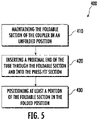
FIG. 5 is a flow diagram illustrating a method for connecting a coupler and a tube to allow the passage of at least one fluid. - A coupler with reduced complexity, when compared to conventional couplers (e.g., which are commonly used to connect siphon tubes to valves in fire extinguishers), a fire extinguisher incorporating the coupler, and a method for connecting a coupler and a tube (e.g., a siphon tube) to allow the passage of at least one fluid (e.g., a fire extinguishing agent) are provided. The coupler may be viewed as a press fit coupler with a secondary securing feature (e.g., the foldable portion). The coupler described herein, through incorporating a foldable portion, may be particularly useful for more reliably connecting the siphon tube to the valve, which may help prevent, or at least mitigate, the fire extinguisher from becoming inoperable. It should be appreciated that the connection between the siphon tube and the coupler may be completed without relying on additional pressure seals, threading, soldering, or glue in certain instances. Instead of relying on threading, soldering, or glue, to increase the holding strength between the coupler and the tube, the coupler relies on a relatively simple foldable portion (e.g., which may be engaged with the tube through crimping the foldable portion). It should be appreciated that although the coupler is described herein to be particularly useful in connecting a siphon tube to a valve (e.g., for a fire extinguisher), the coupler may be useful to provide a connection to any tubing (e.g., water hose, refrigerant line, etc.).
- With reference now to the Figures, a cross-sectional side view of an
exemplary coupler 100 is shown inFIG. 1 . As shown inFIG. 1 , thecoupler 100 may be used for connecting to a tube 220 (e.g., which may be a siphon tube, etc.) that may include acircumferential groove 221. It should be appreciated that connecting thecoupler 100 to atube 220 without a circumferential groove 221 (i.e., to a "plain tube") may negatively affect the connection between thecoupler 100 and the tube 220 (e.g., by altering the external diameter DT of thetube 220 near the interface area). It was found that by adding acircumferential groove 221 to the tube 220 (e.g., through use of a rolling technique, etc.) that such deformation of thetube 220 may be avoided, therein mitigating negative effects on the pressure sealing properties of the press fit connection (i.e., created by thepress fit section 130, described below). As such, in certain instances, thetube 220 described herein must include acircumferential groove 221. - As shown in
FIG. 1 , thecoupler 100 may be viewed to include abody 110 defining a radially outward facingsurface 111, a radially inward facingsurface 112, aproximal end 113, and adistal end 114. As shown, thecoupler 100 may include afoldable section 120 disposed at theproximal end 113 of thebody 110. Thefoldable section 113 may be configured to be manipulated (e.g., through crimping, etc.) so as to change from an unfolded position (shown inFIGs. 1 and2 ) to a folded position (shown inFIG. 3 ). When in an unfolded position, thefoldable section 120 may define an unfolded internal diameter DUF. Likewise, when in a folded position, thefoldable section 120 may define a folded internal diameter DF. It should be appreciated that the folded internal diameter DF may be smaller than the unfolded internal diameter DUF. - As shown in
FIGs. 1-3 , thefoldable section 120 may be configured to receive aproximal end 222 of thetube 220 in the unfolded position (shown inFIGs. 1 and2 ) and to secure to thecircumferential groove 221 of thetube 220 in the folded position (shown inFIG. 3 ). Thisfoldable section 120 may help to increase the reliability of a press fit connection. It is envisioned that thecoupler 100 described herein may be viewed as a pressfit type coupler 100 with increased reliability when compared to existing couplers that do not include thefoldable section 120 as described herein. It is envisioned that thefoldable section 120, by securing to thecircumferential groove 221, may help prevent, or at least mitigate connection failures. For example, instead of solely relying on the strength of the press fit connection, thecoupler 100 described herein includes afoldable section 120 as an additional securing mechanism. - When viewed as a press
fit type coupler 100 thecoupler 100 may be viewed to include apress fit section 130. This pressfit section 130 may be disposed adjacent to thefoldable section 120. As shown inFIGs. 1-3 , thepress fit section 130 may define a fixed internal diameter DPF. This pressfit section 130 may be configured to secure to anexternal surface 223 of thetube 220. It should be appreciated that thecoupler 100 described herein may reliably secure to thetube 220 without the need for additional pressure seals, threading, soldering, or gluing. Instead of relying on these mechanisms to reliably secure to thetube 220, thecoupler 100 may be configured to have differently sized sections. For example, the unfolded internal diameter DUF of thefoldable section 120 may be greater than an external diameter DT of the tube 220 (e.g., which may allow theproximal end 222 of thetube 220 to enter into theproximal end 113 of the coupler 100). In addition, the fixed internal diameter DPF of thepress fit section 130 may be less than the external diameter DT of the tube 220 (e.g., which may allow thepress fit section 130 to secure to theexternal surface 223 of thetube 220 when thetube 220 is inserted). It should be appreciated that thetube 220 may be made of a malleable metal such as aluminum, etc. that allows thetube 220 to fold inward on itself when inserted into thepress fit section 130 of thecoupler 100. To ensure that thetube 220 remain connected with thecoupler 100 in the event of a failure of the connection between thepress fit section 130 and theexternal surface 223 of thetube 200, the folded internal diameter DF of thefoldable section 120 may be less than the external diameter DT of the tube 220 (e.g., so as to secure to thetube 220 when in the folded position). As mentioned above, thefoldable section 120 may be configured to secure to thecircumferential groove 221 of thetube 220. - Although described above that the
coupler 100 may secure to thetube 220 without the use of threading on theproximal end 113, it should be appreciated that thecoupler 100 may include threading, etc. on thedistal end 113. As shown inFIGs. 1-3 , in certain instances thecoupler 100 may be viewed to include a threadedsection 140, which may extend circumferentially around at least a portion of the radially outward facingsurface 111 of thebody 110 toward thedistal end 114 of thecoupler 100. This threadedsection 140, as described below, may enable thecoupler 100 to connect to another components (e.g., a valve of afire extinguisher 200, etc.), which may enable a fluid (e.g., such as fire extinguishing agent) to pass through thetube 220, thecoupler 100, and the valve (when included). It should be appreciated, although not shown, that thecoupler 100 may include an additional foldable section on thedistal end 114 instead of incorporating the threaded section 140 (e.g., to connect to the valve, etc.). - To ensure that the
foldable section 120 of thecoupler 100 aligns with thecircumferential groove 221 of thetube 200 eachsection coupler 100 may be configured according to the dimensioning of thetube 220. For example, thefoldable section 120 may have a width WF that is approximately equal (e.g., within 0.05 inches (about 1mm)) of the width WG of thecircumferential groove 221 of thetube 220. In addition, thepress fit section 130 may have width WPF that is approximately equal (e.g., within 0.05 inches (about 1mm)) to the distance DPE between theproximal end 222 of thetube 220 and the first edge 221(a) of thecircumferential groove 221 of thetube 220. It should be appreciated that the width WG of thecircumferential groove 221 may be defined between the first edge 221(a) and the second edge 221(b) of thecircumferential groove 221. It is envisioned that, when inserted completely, theproximal end 222 of thetube 220 may extend into thecoupler 100 to the combined widths (WF + WPF) of thefoldable section 120 and thepress fit section 130, which may enable thefoldable section 120 to engage thecircumferential groove 221 when placed in the folded position (as shown inFIG. 3 ). It should be appreciated that like thetube 220, thecoupler 100 may be made of a malleable metal such as aluminum, etc., which may enable thefoldable section 120 to be placed in the folded position using any suitable crimping technique, etc. - As mentioned above, the
coupler 100 may be particularly useful as a component of a fire extinguisher 200 (as shown inFIG. 4 ). For example, thecoupler 100 may be useful in connecting a siphontube 220 to avalve 230 to enable the fire extinguishing agent to be siphoned out of thefire extinguisher 200. As shown inFIG. 4 , the fire extinguishing agent may be housed within acylinder 210, which may be viewed to include a neck portion 211 (e.g., positioned near the top of the fire extinguisher 200). The siphontube 220 may extend downwardly into thecylinder 210 from theneck portion 211. The siphontube 220 may be configured to deliver fire extinguishing agent from within thecylinder 210. As shown inFIGs. 1-3 , the siphontube 220 may include acircumferential groove 221. Thecoupler 100, as described above, may connect to the siphontube 220 by incorporating afoldable section 120 and apress fit section 130. Thefoldable section 120 being configured to engage thecircumferential groove 221, and thepress fit section 130 being configured to engage theexternal surface 223 of the siphontube 220. - It is envisioned that the
coupler 100 may help prevent, or at least mitigate, the siphontube 220 from becoming disconnected from thevalve 230, which, if occurring, may cause thefire extinguisher 200 to be inoperable (e.g., unable to effectively expel the fire extinguishing agent). It should be appreciated thefire extinguisher 200 shown inFIG. 4 and described herein may operate in the same manner as a conventional fire extinguisher (e.g., which may incorporate a differently configured coupler (not shown)). For example, as with a conventional fire extinguisher, the fire extinguisher shown inFIG. 4 , may require the user to release/remove apin 244 and squeeze thehandles fire extinguisher 200 described herein may include additional components such as gauges 241 (e.g., to show the pressure within the cylinder 210), hangers 246 (e.g., to allow thefire extinguisher 200 to be mounted in a given location), hose 250 (e.g., to allow the fire extinguishing agent to be directed by the user of thefire extinguisher 200 toward the fire), etc. It should be appreciated that thecoupler 100, and thefire extinguisher 200 described herein may be useful in a number of different settings (e.g., both residential and commercial fire protection). - Regardless of the setting in which the
coupler 100 and/or the fire extinguisher are utilized, the method for connecting thecoupler 100 and thetube 220 may be the same. Anexemplary method 400 for connecting acoupler 100 and atube 220 to allow the passage of at least one fluid (e.g., a fire extinguishing agent, etc.) is shown inFIG. 5 . Themethod 400 may be performed, for example, using theexemplary coupler 100 shown inFIGs. 1-3 , and may be part of the manufacturing process of thefire extinguisher 200 shown inFIG. 4 . Themethod 400 includesstep 410 for maintaining thefoldable section 120 of thecoupler 100 in the unfolded position (as shown inFIG. 1 ), thefoldable section 120 defining an unfolded internal diameter DUF in the unfolded position. Themethod 400 includesstep 420 for inserting aproximal end 222 of thetube 220 through thefoldable section 120 and into the press fit section 130 (as shown inFIG. 2 ). Thepress fit section 130 configured to secure to anexternal surface 223 of thetube 220. Themethod 400 includesstep 430 for positioning (e.g., through crimping, etc.) at least a portion of thefoldable section 120 in the folded position (as shown inFIG. 3 ). Thefoldable section 120 defining a folded internal diameter DF in the folded position. As described above, thefoldable section 120 may be configured to secure to thecircumferential groove 221 of thetube 220 in the folded position. It is envisioned that thismethod 400 may provide a more reliable press fit connection than what is possible by existing couplers. - The use of the terms "a" and "and" and "the" and similar referents, in the context of describing the invention, are to be construed to cover both the singular and the plural, unless otherwise indicated herein or cleared contradicted by context. The use of any and all example, or exemplary language (e.g., "such as", "e.g.", "for example", etc.) provided herein is intended merely to better illuminate the invention and does not pose a limitation on the scope of the invention unless otherwise claimed. No language in the specification should be construed as indicating any non-claimed elements as essential to the practice of the invention.
- While the invention has been described with reference to an exemplary embodiment or embodiments, it will be understood by those skilled in the art that various changes may be made and equivalents may be substituted for elements thereof without departing from the scope of the invention as set out in the appended claims. In addition, many modifications may be made to adapt a particular situation or material to the teachings of the invention as set out in the appended claims without departing from the essential scope thereof. Therefore, it is intended that the present invention not be limited to the particular embodiment disclosed as the best mode contemplated for carrying out this present invention, but that the present invention will include all embodiments falling within the scope of the claims.
Claims (14)
- A coupler (100) for connecting to a tube (220) comprising a circumferential groove (221), the coupler comprising:a body (110) comprising a radially outward facing surface (111), a radially inward facing surface (112), a proximal end (113), and a distal end (114); anda foldable section (120) disposed at the proximal end, the foldable section comprising an unfolded position defining an unfolded internal diameter (DUF) and a folded position defining a folded internal diameter (DF), the foldable section configured to receive a proximal end of the tube in the unfolded position and to secure to the circumferential groove in the folded position.
- The coupler (100) of claim 1, further comprising a press fit section (130) disposed adjacent to the foldable section (120), the press fit section comprising a fixed internal diameter (DPF), the press fit section configured to secure to an external surface (223) of the tube (220).
- The coupler (100) of claim 1 or 2, wherein the unfolded internal diameter (DUF) of the foldable section (120) is greater than an external diameter (DT) of the tube (220), and the folded internal diameter (DF) of the foldable section is less than the external diameter of the tube.
- The coupler (100) of claim 2 or 3, wherein the fixed internal diameter (DPF) of the press fit section (120) is less than the external diameter (DT) of the tube (220).
- The coupler (100) of any preceding claim, further comprising a threaded section (140) extending circumferentially around at least a portion of the radially outward facing surface (111) of the body (110) toward the distal end (114), the threaded section configured to receive a threaded portion of a valve.
- The coupler (100) of any preceding claim, wherein the foldable section (120) comprises a width (WF), the width of the foldable section being approximately equal to a width (WG) of the circumferential groove (221) of the tube (220).
- The coupler (100) of any preceding claim, wherein the press fit section (130) comprises a width (WPF), the width of the press fit section being approximately equal to a distance (DPE) between the proximal end (222) of the tube (220) and a first edge (221a) of the circumferential groove (221) of the tube.
- The coupler (100) of any preceding claim, wherein the body (110) is comprised of a malleable metal.
- A fire extinguisher (200) comprising:a cylinder (110) for storing a fire extinguishing agent, the cylinder comprising a neck portion (211);a siphon tube (220) extending downwardly into the cylinder from the neck portion, the siphon tube configured to deliver the fire extinguishing agent from within the cylinder, the siphon tube comprising a circumferential groove (221); andthe coupler (100) of any preceding claim for connecting to a proximal end of the siphon tube.
- A method for connecting a coupler (100) and a tube (220) to allow the passage of at least one fluid, the coupler comprising a foldable section (120) disposed at a proximal end (113), and a press fit section (130) disposed adjacent to the foldable section, the method comprising:maintaining the foldable section of the coupler in the unfolded position, the foldable section comprising an unfolded internal diameter (DUF) in the unfolded position;inserting a proximal end of the tube through the foldable section and into the press fit section, the press fit section configured to secure to an external surface (223) of the tube; andpositioning at least a portion of the foldable section in the folded position, the foldable section comprising a folded internal diameter (DF) in the folded position, the foldable section configured to secure to a circumferential groove (221) of the tube in the folded position.
- The method of claim 10, wherein the positioning of at least a portion of the foldable section (120) is completed by crimping.
- The method of claim 10 or 11, the unfolded internal diameter (DUF) of the foldable section is greater than an external diameter (DT) of the siphon tube (220), and the folded internal diameter (DF) of the foldable section and a fixed internal diameter (DPF) of the press fit section are less than the external diameter of the siphon tube (DT).
- The method of claim 10, 11, or 12, wherein the at least one fluid is a fire extinguishing agent.
- The method of any of claims 10 to 13, wherein the coupler is as claimed in any of claims 1 to 8.
Applications Claiming Priority (1)
| Application Number | Priority Date | Filing Date | Title |
|---|---|---|---|
| US202063198434P | 2020-10-19 | 2020-10-19 |
Publications (2)
| Publication Number | Publication Date |
|---|---|
| EP3985292A1 true EP3985292A1 (en) | 2022-04-20 |
| EP3985292B1 EP3985292B1 (en) | 2024-08-14 |
Family
ID=78134879
Family Applications (1)
| Application Number | Title | Priority Date | Filing Date |
|---|---|---|---|
| EP21202294.1A Active EP3985292B1 (en) | 2020-10-19 | 2021-10-12 | Fire extinguisher with a push and crimp coupler |
Country Status (3)
| Country | Link |
|---|---|
| US (1) | US20220120363A1 (en) |
| EP (1) | EP3985292B1 (en) |
| CA (1) | CA3133849A1 (en) |
Families Citing this family (1)
| Publication number | Priority date | Publication date | Assignee | Title |
|---|---|---|---|---|
| GB2600124B (en) * | 2020-10-21 | 2024-12-25 | Ardent Ltd | Pressurised container |
Citations (5)
| Publication number | Priority date | Publication date | Assignee | Title |
|---|---|---|---|---|
| US2001204A (en) * | 1934-03-03 | 1935-05-14 | James A Long | Pipe joint and method of making the same |
| US2574625A (en) * | 1946-11-21 | 1951-11-13 | Flex O Tube Company | Method of making high-pressure swivel hose couplings |
| US3858914A (en) * | 1973-07-25 | 1975-01-07 | Brass Craft Mfg Co | Transition pipe connection |
| EP0276483A1 (en) * | 1987-01-23 | 1988-08-03 | Behr GmbH & Co. | Tube joint, especially for a flat tube evaporator |
| WO2010074684A1 (en) * | 2008-12-23 | 2010-07-01 | Utc Fire & Security Corporation | Fire extinguisher and discharge nozzle assembly |
Family Cites Families (1)
| Publication number | Priority date | Publication date | Assignee | Title |
|---|---|---|---|---|
| KR100311302B1 (en) * | 1999-11-25 | 2001-10-18 | 남윤상 | Hand-Operated Combined Automatic Fire Extinguisher |
-
2021
- 2021-10-08 CA CA3133849A patent/CA3133849A1/en active Pending
- 2021-10-11 US US17/450,468 patent/US20220120363A1/en not_active Abandoned
- 2021-10-12 EP EP21202294.1A patent/EP3985292B1/en active Active
Patent Citations (5)
| Publication number | Priority date | Publication date | Assignee | Title |
|---|---|---|---|---|
| US2001204A (en) * | 1934-03-03 | 1935-05-14 | James A Long | Pipe joint and method of making the same |
| US2574625A (en) * | 1946-11-21 | 1951-11-13 | Flex O Tube Company | Method of making high-pressure swivel hose couplings |
| US3858914A (en) * | 1973-07-25 | 1975-01-07 | Brass Craft Mfg Co | Transition pipe connection |
| EP0276483A1 (en) * | 1987-01-23 | 1988-08-03 | Behr GmbH & Co. | Tube joint, especially for a flat tube evaporator |
| WO2010074684A1 (en) * | 2008-12-23 | 2010-07-01 | Utc Fire & Security Corporation | Fire extinguisher and discharge nozzle assembly |
Also Published As
| Publication number | Publication date |
|---|---|
| US20220120363A1 (en) | 2022-04-21 |
| CA3133849A1 (en) | 2022-04-19 |
| EP3985292B1 (en) | 2024-08-14 |
Similar Documents
| Publication | Publication Date | Title |
|---|---|---|
| US12429152B2 (en) | Tubular connector | |
| CA2950322C (en) | Push-to-connect fitting with release assistance assembly and device | |
| US8844974B1 (en) | Cross platform grip ring release device and method | |
| EP3985292B1 (en) | Fire extinguisher with a push and crimp coupler | |
| CN101305232A (en) | Fitting | |
| JP2016205432A (en) | Seal device | |
| JP2009273486A (en) | Fire-fighting hose coupling metal fitting | |
| KR101865460B1 (en) | Flexible Joint Pipe Improved Sealing Quality of Packing | |
| JP2010078027A5 (en) | ||
| US20250198529A1 (en) | Schrader Valve Adapter and Optimizer | |
| US20130193683A1 (en) | High pressure fitting | |
| US20070046026A1 (en) | Tube-to-tube connection | |
| JP2007162730A (en) | Hose fittings | |
| CN111936779A (en) | Anti-rotation fitting | |
| JP5718159B2 (en) | Firefighting fittings | |
| WO2002057678A1 (en) | Improved tube fitting sealing member | |
| JP6915876B2 (en) | Plug-in joint and its receiver | |
| KR102290701B1 (en) | Pipe joint member and pipe structure using the same | |
| US11543060B2 (en) | Pipe-fitting device for connecting pipes having different diameters | |
| KR101073691B1 (en) | Hub Type Structure for Valve | |
| JP6805909B2 (en) | Pipe fitting | |
| EP3529525B1 (en) | System having pressurized fluid flowing therethrough comprising a coupling nut | |
| CN216553965U (en) | Joint seat | |
| JP4610436B2 (en) | Water filling method for training water fire extinguisher and training fire extinguisher | |
| CN211667356U (en) | Quick connector |
Legal Events
| Date | Code | Title | Description |
|---|---|---|---|
| PUAI | Public reference made under article 153(3) epc to a published international application that has entered the european phase |
Free format text: ORIGINAL CODE: 0009012 |
|
| STAA | Information on the status of an ep patent application or granted ep patent |
Free format text: STATUS: THE APPLICATION HAS BEEN PUBLISHED |
|
| AK | Designated contracting states |
Kind code of ref document: A1 Designated state(s): AL AT BE BG CH CY CZ DE DK EE ES FI FR GB GR HR HU IE IS IT LI LT LU LV MC MK MT NL NO PL PT RO RS SE SI SK SM TR |
|
| STAA | Information on the status of an ep patent application or granted ep patent |
Free format text: STATUS: REQUEST FOR EXAMINATION WAS MADE |
|
| 17P | Request for examination filed |
Effective date: 20221019 |
|
| RBV | Designated contracting states (corrected) |
Designated state(s): AL AT BE BG CH CY CZ DE DK EE ES FI FR GB GR HR HU IE IS IT LI LT LU LV MC MK MT NL NO PL PT RO RS SE SI SK SM TR |
|
| GRAP | Despatch of communication of intention to grant a patent |
Free format text: ORIGINAL CODE: EPIDOSNIGR1 |
|
| STAA | Information on the status of an ep patent application or granted ep patent |
Free format text: STATUS: GRANT OF PATENT IS INTENDED |
|
| RIC1 | Information provided on ipc code assigned before grant |
Ipc: A62C 13/64 20060101ALI20240226BHEP Ipc: A62C 13/00 20060101ALI20240226BHEP Ipc: F16L 13/16 20060101AFI20240226BHEP |
|
| INTG | Intention to grant announced |
Effective date: 20240315 |
|
| GRAS | Grant fee paid |
Free format text: ORIGINAL CODE: EPIDOSNIGR3 |
|
| GRAA | (expected) grant |
Free format text: ORIGINAL CODE: 0009210 |
|
| STAA | Information on the status of an ep patent application or granted ep patent |
Free format text: STATUS: THE PATENT HAS BEEN GRANTED |
|
| AK | Designated contracting states |
Kind code of ref document: B1 Designated state(s): AL AT BE BG CH CY CZ DE DK EE ES FI FR GB GR HR HU IE IS IT LI LT LU LV MC MK MT NL NO PL PT RO RS SE SI SK SM TR |
|
| REG | Reference to a national code |
Ref country code: GB Ref legal event code: FG4D |
|
| REG | Reference to a national code |
Ref country code: CH Ref legal event code: EP |
|
| REG | Reference to a national code |
Ref country code: DE Ref legal event code: R096 Ref document number: 602021017122 Country of ref document: DE |
|
| REG | Reference to a national code |
Ref country code: IE Ref legal event code: FG4D |
|
| REG | Reference to a national code |
Ref country code: LT Ref legal event code: MG9D |
|
| REG | Reference to a national code |
Ref country code: NL Ref legal event code: MP Effective date: 20240814 |
|
| PG25 | Lapsed in a contracting state [announced via postgrant information from national office to epo] |
Ref country code: NO Free format text: LAPSE BECAUSE OF FAILURE TO SUBMIT A TRANSLATION OF THE DESCRIPTION OR TO PAY THE FEE WITHIN THE PRESCRIBED TIME-LIMIT Effective date: 20241114 |
|
| REG | Reference to a national code |
Ref country code: AT Ref legal event code: MK05 Ref document number: 1713585 Country of ref document: AT Kind code of ref document: T Effective date: 20240814 |
|
| PG25 | Lapsed in a contracting state [announced via postgrant information from national office to epo] |
Ref country code: NL Free format text: LAPSE BECAUSE OF FAILURE TO SUBMIT A TRANSLATION OF THE DESCRIPTION OR TO PAY THE FEE WITHIN THE PRESCRIBED TIME-LIMIT Effective date: 20240814 Ref country code: GR Free format text: LAPSE BECAUSE OF FAILURE TO SUBMIT A TRANSLATION OF THE DESCRIPTION OR TO PAY THE FEE WITHIN THE PRESCRIBED TIME-LIMIT Effective date: 20241115 Ref country code: PL Free format text: LAPSE BECAUSE OF FAILURE TO SUBMIT A TRANSLATION OF THE DESCRIPTION OR TO PAY THE FEE WITHIN THE PRESCRIBED TIME-LIMIT Effective date: 20240814 Ref country code: FI Free format text: LAPSE BECAUSE OF FAILURE TO SUBMIT A TRANSLATION OF THE DESCRIPTION OR TO PAY THE FEE WITHIN THE PRESCRIBED TIME-LIMIT Effective date: 20240814 Ref country code: PT Free format text: LAPSE BECAUSE OF FAILURE TO SUBMIT A TRANSLATION OF THE DESCRIPTION OR TO PAY THE FEE WITHIN THE PRESCRIBED TIME-LIMIT Effective date: 20241216 |
|
| PG25 | Lapsed in a contracting state [announced via postgrant information from national office to epo] |
Ref country code: BG Free format text: LAPSE BECAUSE OF FAILURE TO SUBMIT A TRANSLATION OF THE DESCRIPTION OR TO PAY THE FEE WITHIN THE PRESCRIBED TIME-LIMIT Effective date: 20240814 |
|
| PG25 | Lapsed in a contracting state [announced via postgrant information from national office to epo] |
Ref country code: LV Free format text: LAPSE BECAUSE OF FAILURE TO SUBMIT A TRANSLATION OF THE DESCRIPTION OR TO PAY THE FEE WITHIN THE PRESCRIBED TIME-LIMIT Effective date: 20240814 |
|
| PG25 | Lapsed in a contracting state [announced via postgrant information from national office to epo] |
Ref country code: IS Free format text: LAPSE BECAUSE OF FAILURE TO SUBMIT A TRANSLATION OF THE DESCRIPTION OR TO PAY THE FEE WITHIN THE PRESCRIBED TIME-LIMIT Effective date: 20241214 Ref country code: AT Free format text: LAPSE BECAUSE OF FAILURE TO SUBMIT A TRANSLATION OF THE DESCRIPTION OR TO PAY THE FEE WITHIN THE PRESCRIBED TIME-LIMIT Effective date: 20240814 |
|
| PG25 | Lapsed in a contracting state [announced via postgrant information from national office to epo] |
Ref country code: HR Free format text: LAPSE BECAUSE OF FAILURE TO SUBMIT A TRANSLATION OF THE DESCRIPTION OR TO PAY THE FEE WITHIN THE PRESCRIBED TIME-LIMIT Effective date: 20240814 |
|
| PG25 | Lapsed in a contracting state [announced via postgrant information from national office to epo] |
Ref country code: RS Free format text: LAPSE BECAUSE OF FAILURE TO SUBMIT A TRANSLATION OF THE DESCRIPTION OR TO PAY THE FEE WITHIN THE PRESCRIBED TIME-LIMIT Effective date: 20241114 Ref country code: ES Free format text: LAPSE BECAUSE OF FAILURE TO SUBMIT A TRANSLATION OF THE DESCRIPTION OR TO PAY THE FEE WITHIN THE PRESCRIBED TIME-LIMIT Effective date: 20240814 |
|
| PG25 | Lapsed in a contracting state [announced via postgrant information from national office to epo] |
Ref country code: RS Free format text: LAPSE BECAUSE OF FAILURE TO SUBMIT A TRANSLATION OF THE DESCRIPTION OR TO PAY THE FEE WITHIN THE PRESCRIBED TIME-LIMIT Effective date: 20241114 Ref country code: PT Free format text: LAPSE BECAUSE OF FAILURE TO SUBMIT A TRANSLATION OF THE DESCRIPTION OR TO PAY THE FEE WITHIN THE PRESCRIBED TIME-LIMIT Effective date: 20241216 Ref country code: PL Free format text: LAPSE BECAUSE OF FAILURE TO SUBMIT A TRANSLATION OF THE DESCRIPTION OR TO PAY THE FEE WITHIN THE PRESCRIBED TIME-LIMIT Effective date: 20240814 Ref country code: NO Free format text: LAPSE BECAUSE OF FAILURE TO SUBMIT A TRANSLATION OF THE DESCRIPTION OR TO PAY THE FEE WITHIN THE PRESCRIBED TIME-LIMIT Effective date: 20241114 Ref country code: NL Free format text: LAPSE BECAUSE OF FAILURE TO SUBMIT A TRANSLATION OF THE DESCRIPTION OR TO PAY THE FEE WITHIN THE PRESCRIBED TIME-LIMIT Effective date: 20240814 Ref country code: LV Free format text: LAPSE BECAUSE OF FAILURE TO SUBMIT A TRANSLATION OF THE DESCRIPTION OR TO PAY THE FEE WITHIN THE PRESCRIBED TIME-LIMIT Effective date: 20240814 Ref country code: IS Free format text: LAPSE BECAUSE OF FAILURE TO SUBMIT A TRANSLATION OF THE DESCRIPTION OR TO PAY THE FEE WITHIN THE PRESCRIBED TIME-LIMIT Effective date: 20241214 Ref country code: HR Free format text: LAPSE BECAUSE OF FAILURE TO SUBMIT A TRANSLATION OF THE DESCRIPTION OR TO PAY THE FEE WITHIN THE PRESCRIBED TIME-LIMIT Effective date: 20240814 Ref country code: GR Free format text: LAPSE BECAUSE OF FAILURE TO SUBMIT A TRANSLATION OF THE DESCRIPTION OR TO PAY THE FEE WITHIN THE PRESCRIBED TIME-LIMIT Effective date: 20241115 Ref country code: FI Free format text: LAPSE BECAUSE OF FAILURE TO SUBMIT A TRANSLATION OF THE DESCRIPTION OR TO PAY THE FEE WITHIN THE PRESCRIBED TIME-LIMIT Effective date: 20240814 Ref country code: ES Free format text: LAPSE BECAUSE OF FAILURE TO SUBMIT A TRANSLATION OF THE DESCRIPTION OR TO PAY THE FEE WITHIN THE PRESCRIBED TIME-LIMIT Effective date: 20240814 Ref country code: BG Free format text: LAPSE BECAUSE OF FAILURE TO SUBMIT A TRANSLATION OF THE DESCRIPTION OR TO PAY THE FEE WITHIN THE PRESCRIBED TIME-LIMIT Effective date: 20240814 Ref country code: AT Free format text: LAPSE BECAUSE OF FAILURE TO SUBMIT A TRANSLATION OF THE DESCRIPTION OR TO PAY THE FEE WITHIN THE PRESCRIBED TIME-LIMIT Effective date: 20240814 |
|
| PG25 | Lapsed in a contracting state [announced via postgrant information from national office to epo] |
Ref country code: DK Free format text: LAPSE BECAUSE OF FAILURE TO SUBMIT A TRANSLATION OF THE DESCRIPTION OR TO PAY THE FEE WITHIN THE PRESCRIBED TIME-LIMIT Effective date: 20240814 Ref country code: SM Free format text: LAPSE BECAUSE OF FAILURE TO SUBMIT A TRANSLATION OF THE DESCRIPTION OR TO PAY THE FEE WITHIN THE PRESCRIBED TIME-LIMIT Effective date: 20240814 Ref country code: RO Free format text: LAPSE BECAUSE OF FAILURE TO SUBMIT A TRANSLATION OF THE DESCRIPTION OR TO PAY THE FEE WITHIN THE PRESCRIBED TIME-LIMIT Effective date: 20240814 |
|
| PG25 | Lapsed in a contracting state [announced via postgrant information from national office to epo] |
Ref country code: EE Free format text: LAPSE BECAUSE OF FAILURE TO SUBMIT A TRANSLATION OF THE DESCRIPTION OR TO PAY THE FEE WITHIN THE PRESCRIBED TIME-LIMIT Effective date: 20240814 |
|
| PG25 | Lapsed in a contracting state [announced via postgrant information from national office to epo] |
Ref country code: CZ Free format text: LAPSE BECAUSE OF FAILURE TO SUBMIT A TRANSLATION OF THE DESCRIPTION OR TO PAY THE FEE WITHIN THE PRESCRIBED TIME-LIMIT Effective date: 20240814 |
|
| PG25 | Lapsed in a contracting state [announced via postgrant information from national office to epo] |
Ref country code: IT Free format text: LAPSE BECAUSE OF FAILURE TO SUBMIT A TRANSLATION OF THE DESCRIPTION OR TO PAY THE FEE WITHIN THE PRESCRIBED TIME-LIMIT Effective date: 20240814 Ref country code: SK Free format text: LAPSE BECAUSE OF FAILURE TO SUBMIT A TRANSLATION OF THE DESCRIPTION OR TO PAY THE FEE WITHIN THE PRESCRIBED TIME-LIMIT Effective date: 20240814 |
|
| REG | Reference to a national code |
Ref country code: DE Ref legal event code: R097 Ref document number: 602021017122 Country of ref document: DE |
|
| REG | Reference to a national code |
Ref country code: CH Ref legal event code: PL |
|
| PLBE | No opposition filed within time limit |
Free format text: ORIGINAL CODE: 0009261 |
|
| STAA | Information on the status of an ep patent application or granted ep patent |
Free format text: STATUS: NO OPPOSITION FILED WITHIN TIME LIMIT |
|
| PG25 | Lapsed in a contracting state [announced via postgrant information from national office to epo] |
Ref country code: MC Free format text: LAPSE BECAUSE OF FAILURE TO SUBMIT A TRANSLATION OF THE DESCRIPTION OR TO PAY THE FEE WITHIN THE PRESCRIBED TIME-LIMIT Effective date: 20240814 |
|
| PG25 | Lapsed in a contracting state [announced via postgrant information from national office to epo] |
Ref country code: LU Free format text: LAPSE BECAUSE OF NON-PAYMENT OF DUE FEES Effective date: 20241012 Ref country code: BE Free format text: LAPSE BECAUSE OF NON-PAYMENT OF DUE FEES Effective date: 20241031 |
|
| 26N | No opposition filed |
Effective date: 20250515 |
|
| PG25 | Lapsed in a contracting state [announced via postgrant information from national office to epo] |
Ref country code: CH Free format text: LAPSE BECAUSE OF NON-PAYMENT OF DUE FEES Effective date: 20241031 |
|
| REG | Reference to a national code |
Ref country code: BE Ref legal event code: MM Effective date: 20241031 |
|
| PG25 | Lapsed in a contracting state [announced via postgrant information from national office to epo] |
Ref country code: SE Free format text: LAPSE BECAUSE OF FAILURE TO SUBMIT A TRANSLATION OF THE DESCRIPTION OR TO PAY THE FEE WITHIN THE PRESCRIBED TIME-LIMIT Effective date: 20240814 |
|
| PGFP | Annual fee paid to national office [announced via postgrant information from national office to epo] |
Ref country code: GB Payment date: 20250923 Year of fee payment: 5 |
|
| PGFP | Annual fee paid to national office [announced via postgrant information from national office to epo] |
Ref country code: FR Payment date: 20250924 Year of fee payment: 5 |
|
| PG25 | Lapsed in a contracting state [announced via postgrant information from national office to epo] |
Ref country code: IE Free format text: LAPSE BECAUSE OF NON-PAYMENT OF DUE FEES Effective date: 20241012 |
|
| PGFP | Annual fee paid to national office [announced via postgrant information from national office to epo] |
Ref country code: DE Payment date: 20250923 Year of fee payment: 5 |
|
| PG25 | Lapsed in a contracting state [announced via postgrant information from national office to epo] |
Ref country code: CY Free format text: LAPSE BECAUSE OF FAILURE TO SUBMIT A TRANSLATION OF THE DESCRIPTION OR TO PAY THE FEE WITHIN THE PRESCRIBED TIME-LIMIT; INVALID AB INITIO Effective date: 20211012 |
|
| PG25 | Lapsed in a contracting state [announced via postgrant information from national office to epo] |
Ref country code: HU Free format text: LAPSE BECAUSE OF FAILURE TO SUBMIT A TRANSLATION OF THE DESCRIPTION OR TO PAY THE FEE WITHIN THE PRESCRIBED TIME-LIMIT; INVALID AB INITIO Effective date: 20211012 |