EP3985255A1 - Pump system - Google Patents
Pump system Download PDFInfo
- Publication number
- EP3985255A1 EP3985255A1 EP20822821.3A EP20822821A EP3985255A1 EP 3985255 A1 EP3985255 A1 EP 3985255A1 EP 20822821 A EP20822821 A EP 20822821A EP 3985255 A1 EP3985255 A1 EP 3985255A1
- Authority
- EP
- European Patent Office
- Prior art keywords
- flow path
- pressure
- increasing portion
- valve device
- fluid
- Prior art date
- Legal status (The legal status is an assumption and is not a legal conclusion. Google has not performed a legal analysis and makes no representation as to the accuracy of the status listed.)
- Granted
Links
Images
Classifications
-
- F—MECHANICAL ENGINEERING; LIGHTING; HEATING; WEAPONS; BLASTING
- F04—POSITIVE - DISPLACEMENT MACHINES FOR LIQUIDS; PUMPS FOR LIQUIDS OR ELASTIC FLUIDS
- F04C—ROTARY-PISTON, OR OSCILLATING-PISTON, POSITIVE-DISPLACEMENT MACHINES FOR LIQUIDS; ROTARY-PISTON, OR OSCILLATING-PISTON, POSITIVE-DISPLACEMENT PUMPS
- F04C2/00—Rotary-piston machines or pumps
- F04C2/08—Rotary-piston machines or pumps of intermeshing-engagement type, i.e. with engagement of co-operating members similar to that of toothed gearing
- F04C2/12—Rotary-piston machines or pumps of intermeshing-engagement type, i.e. with engagement of co-operating members similar to that of toothed gearing of other than internal-axis type
- F04C2/14—Rotary-piston machines or pumps of intermeshing-engagement type, i.e. with engagement of co-operating members similar to that of toothed gearing of other than internal-axis type with toothed rotary pistons
-
- F—MECHANICAL ENGINEERING; LIGHTING; HEATING; WEAPONS; BLASTING
- F04—POSITIVE - DISPLACEMENT MACHINES FOR LIQUIDS; PUMPS FOR LIQUIDS OR ELASTIC FLUIDS
- F04C—ROTARY-PISTON, OR OSCILLATING-PISTON, POSITIVE-DISPLACEMENT MACHINES FOR LIQUIDS; ROTARY-PISTON, OR OSCILLATING-PISTON, POSITIVE-DISPLACEMENT PUMPS
- F04C14/00—Control of, monitoring of, or safety arrangements for, machines, pumps or pumping installations
- F04C14/02—Control of, monitoring of, or safety arrangements for, machines, pumps or pumping installations specially adapted for several machines or pumps connected in series or in parallel
-
- F—MECHANICAL ENGINEERING; LIGHTING; HEATING; WEAPONS; BLASTING
- F04—POSITIVE - DISPLACEMENT MACHINES FOR LIQUIDS; PUMPS FOR LIQUIDS OR ELASTIC FLUIDS
- F04C—ROTARY-PISTON, OR OSCILLATING-PISTON, POSITIVE-DISPLACEMENT MACHINES FOR LIQUIDS; ROTARY-PISTON, OR OSCILLATING-PISTON, POSITIVE-DISPLACEMENT PUMPS
- F04C14/00—Control of, monitoring of, or safety arrangements for, machines, pumps or pumping installations
- F04C14/24—Control of, monitoring of, or safety arrangements for, machines, pumps or pumping installations characterised by using valves controlling pressure or flow rate, e.g. discharge valves or unloading valves
- F04C14/26—Control of, monitoring of, or safety arrangements for, machines, pumps or pumping installations characterised by using valves controlling pressure or flow rate, e.g. discharge valves or unloading valves using bypass channels
-
- F—MECHANICAL ENGINEERING; LIGHTING; HEATING; WEAPONS; BLASTING
- F04—POSITIVE - DISPLACEMENT MACHINES FOR LIQUIDS; PUMPS FOR LIQUIDS OR ELASTIC FLUIDS
- F04C—ROTARY-PISTON, OR OSCILLATING-PISTON, POSITIVE-DISPLACEMENT MACHINES FOR LIQUIDS; ROTARY-PISTON, OR OSCILLATING-PISTON, POSITIVE-DISPLACEMENT PUMPS
- F04C15/00—Component parts, details or accessories of machines, pumps or pumping installations, not provided for in groups F04C2/00 - F04C14/00
- F04C15/06—Arrangements for admission or discharge of the working fluid, e.g. constructional features of the inlet or outlet
-
- F—MECHANICAL ENGINEERING; LIGHTING; HEATING; WEAPONS; BLASTING
- F04—POSITIVE - DISPLACEMENT MACHINES FOR LIQUIDS; PUMPS FOR LIQUIDS OR ELASTIC FLUIDS
- F04C—ROTARY-PISTON, OR OSCILLATING-PISTON, POSITIVE-DISPLACEMENT MACHINES FOR LIQUIDS; ROTARY-PISTON, OR OSCILLATING-PISTON, POSITIVE-DISPLACEMENT PUMPS
- F04C2210/00—Fluid
- F04C2210/20—Fluid liquid, i.e. incompressible
- F04C2210/203—Fuel
-
- F—MECHANICAL ENGINEERING; LIGHTING; HEATING; WEAPONS; BLASTING
- F04—POSITIVE - DISPLACEMENT MACHINES FOR LIQUIDS; PUMPS FOR LIQUIDS OR ELASTIC FLUIDS
- F04C—ROTARY-PISTON, OR OSCILLATING-PISTON, POSITIVE-DISPLACEMENT MACHINES FOR LIQUIDS; ROTARY-PISTON, OR OSCILLATING-PISTON, POSITIVE-DISPLACEMENT PUMPS
- F04C2240/00—Components
- F04C2240/30—Casings or housings
Definitions
- the present disclosure relates to a pump system.
- Patent Literature 1 discloses a fuel system which pressurizes and supplies fuel.
- fuel is pressurized using a triple-gear pump.
- the triple-gear pump two pressure-increasing portions are formed on three gears and it is possible to switch between a state in which the two pressure-increasing portions are connected in series through flow paths and a state in which the two pressure-increasing portions are connected in parallel through flow paths.
- the two pressure-increasing portions are connected in parallel when a discharge flow rate is desired to be increased and the two pressure-increasing portions are connected in series when a discharge flow rate is desired to be decreased.
- Patent Document 1 Japanese Unexamined Patent Application, First Publication No. 2014-137053
- Patent Literature 1 described above, the switching between the parallel state and the series state of the pressure-increasing portions is performed only by opening and closing one variable throttle valve. For this reason, on an outlet side, when the parallel state is switched to the series state, a flow rate of fuel rapidly and significantly changes to about half, causing pressure pulsation. If the variable throttle valve is operated gently in order to improve this problem, a switching operation takes a long time.
- the present disclosure is made in view of the above problems, and an object of the present disclosure is to minimize pressure pulsation (fluid pressure pulsation) on an outlet side when switching between a series state and a parallel state is performed in a pump system.
- a pump system of a first aspect of the present disclosure for solving the above problems includes a triple-gear pump which pressurizes a fluid using three gears; an outlet flow path which guides the fluid from a first pressure-increasing portion to an outlet; a first flow path which guides the fluid from the first pressure-increasing portion to a second pressure-increasing portion; a second flow path which guides the fluid from the second pressure-increasing portion to the outlet flow path; a third flow path connected to the first flow path and the second flow path; a first valve device provided in the first flow path; a second valve device provided in the second flow path; and a control device which controls the first valve device, wherein, when the first pressure-increasing portion and the second pressure-increasing portion are switched from a parallel state to a series state, the control device causes the first valve device to open after the second valve device is closed.
- a second aspect of the present disclosure is that in the pump system of the first aspect, the second valve device is a check valve which blocks an inflow of the fluid from the outlet flow path toward the second pressure-increasing portion.
- a third aspect of the present disclosure is that the pump system of the first or second aspect includes: a third valve device provided in the third flow path and controlled by the control device, wherein, when the first pressure-increasing portion and the second pressure-increasing portion are switched from the parallel state to the series state, the control device causes the third valve device to open before the first valve device is opened.
- a fourth aspect of the present disclosure is that the pump system of the first to third aspects includes: a fluid supply flow path connected to the first pressure-increasing portion and the third flow path and configured to supply the fluid from outside; and a check valve provided in the fluid supply flow path.
- a first valve device is closed after a second valve device is closed. For this reason, after a flow of each flow path has been changed, a fluid flows from a first pressure-increasing portion into a second pressure-increasing portion and changes in flow rate and pressure in an outlet flow path become gradual. Therefore, it is possible to minimize pressure pulsation on an outlet side.
- a pump system 1 is, for example, a device which pressurizes liquid fuel (a fluid) and includes a casing 2, three gears 3a, 3b, and 3c, a first throttle valve 4 (a first valve device), a second throttle valve 5 (a third valve device), a first check valve 6, a second check valve 7 (a second valve device), a fuel controller 8 (a control device), a supply flow path R, a first flow path R1, a second flow path R2, a third flow path R3, and an outlet flow path R4.
- the supply flow path R guides fuel to an inlet of a first pressure-increasing portion A and the third flow path R3.
- liquid fuel guided from outside through the supply flow path R is pressurized and discharged through the outlet flow path R4.
- the casing 2 is a container having the three gears 3a, 3b, and 3c accommodated therein.
- a volume chamber in which liquid fuel is pressurized is formed in a first pressure-increasing portion A and a second pressure-increasing portion B which will be described later.
- the gears 3a, 3b, and 3c mesh with each other and are rotated due to a power (not shown) which operates based on an instruction of the fuel controller 8.
- the power may be derived, for example, from an output shaft of an electric motor, a turbine connected to the pump system 1, or the like.
- the gear 3b meshes with the gear 3a and the gear 3c. That is to say, the triple-gear pump is constituted by the first pressure-increasing portion A in the present disclosure using the gear 3a and the gear 3b and the second pressure-increasing portion B in the present disclosure using the gear 3b and the gear 3c.
- Such a first pressure-increasing portion A is connected to a branch flow path R5 which branches from the supply flow path R and is connected to the outlet flow path R4 on the outlet side of the first pressure-increasing portion A.
- the second pressure-increasing portion B is connected to the first flow path R1 on the inlet side of the second pressure-increasing portion B and is connected to the second flow path R2 on the outlet side of the second pressure-increasing portion B.
- the first flow path R1 is connected to the outlet flow path R4. Furthermore, a downstream end portion of the second flow path R2 is connected to the outlet flow path R4.
- the third flow path R3 is connected to the supply flow path R, the first flow path R1, and an upstream of the second flow path R2. That is to say, the first pressure-increasing portion A and the second pressure-increasing portion B are connected in series through the first flow path R1 and the second flow path R2. Moreover, the first pressure-increasing portion A and the second pressure-increasing portion B are connected in parallel through the first flow path R1 and the third flow path R3 .
- the first throttle valve 4 is provided in the first flow path R1 and thereby it is possible to change a flow rate of liquid fuel flowing from the first pressure-increasing portion A to the second pressure-increasing portion B.
- the second throttle valve 5 is provided in the vicinity of an end in the third flow path R3 on a side connected to the second flow path R2 and thereby it is possible to change an amount of liquid fuel discharged from the second pressure-increasing portion B and flowing into the third flow path R3. Furthermore, the first throttle valve 4 and the second throttle valve 5 are electric valves and are controlled by the fuel controller 8.
- the first check valve 6 is provided in the supply flow path R, is driven due to a differential pressure between liquid fuel upstream of the first check valve 6 and the liquid fuel downstream of the first check valve 6 (the liquid fuel in the third flow path R3) in the supply flow path R, and blocks the inflow of the liquid fuel from the third flow path R3 to the supply flow path R.
- the second check valve 7 is provided in the second flow path R2, is driven due to a differential pressure between the liquid fuel upstream of the second check valve 7 and the liquid fuel downstream of the second check valve 7 (the liquid fuel in the outlet flow path R4 side) in the second flow path R2, and blocks the inflow of the liquid fuel from the outlet flow path R4 toward the second pressure-increasing portion B.
- the fuel controller 8 may include a central processing unit (CPU), a memory such as a random-access memory (RAM) and a read-only memory (ROM), a storage device such as a hard disk drive (HDD) and a solid-state drive (SSD), and an input/output device.
- CPU central processing unit
- RAM random-access memory
- ROM read-only memory
- HDD hard disk drive
- SSD solid-state drive
- the flow rate in which the liquid fuel flows into the second pressure-increasing portion B is larger than the flow rate in which the liquid fuel is discharged from the second pressure-increasing portion B, the liquid fuel is not pressurized in the flow paths upstream of the second pressure-increasing portion B (the first flow path R1 and the third flow path R3).
- the second throttle valve 5 is gradually opened over about 1 second. Through such an operation, the discharge flow rate of the pump system 1 is halved. Furthermore, the pressure on the outlet side (an outlet pressure and the pressure of the liquid fuel in the outlet flow path R4) slightly decreases due to pulsation and then returns to the original pressure.
- the fuel controller 8 causes the first throttle valve 4 to gradually open, the liquid fuel discharged from the first pressure-increasing portion A flows into the first flow path R1.
- the flow rate flowing into the second pressure-increasing portion B gradually increases and the liquid fuel of the flow paths upstream of the second pressure-increasing portion B (the first flow path R1 and the third flow path R3) is pressurized. Therefore, in the supply flow path R connected to the third flow path R3, the pressure of the liquid fuel downstream of the first check valve 6 becomes larger than the pressure of the liquid fuel upstream of the first check valve 6.
- the first check valve 6 is closed.
- the discharge flow rate of the pump system 1 is slightly increased due to pulsation when the first throttle valve 4 is opened and returns to the original discharge flow rate.
- the outlet pressure also increases slightly and returns to the original pressure.
- the first throttle valve 4 If the first throttle valve 4 is fully opened, the pressure of the liquid fuel in the third flow path R3 becomes equal to the pressure of the liquid fuel in the first flow path R1. Thus, the inflow of the liquid fuel from the first flow path R1 to the third flow path R3 stops. Therefore, the first pressure-increasing portion A and the second pressure-increasing portion B change to a series state. That is to say, the liquid fuel discharged from the first pressure-increasing portion A passes through the first flow path R1 and flows into the second pressure-increasing portion B and is discharged through the outlet flow path R4. As a result, the pump system 1 is changed from a parallel state to a series state. At this time, since the liquid fuel has the same flow rate upstream and downstream of the second pressure-increasing portion B, the pressure of the liquid fuel does not increase in the second pressure-increasing portion B.
- Such a series of switching operations is performed in about 2 seconds. Furthermore, when the switching from a series state to a parallel state is performed, the pump system 1 operates each valve in the reverse order of the above.
- the pump system 1 when the pump system 1 is changed from the parallel state to the series state, it is possible to gently pressurize the liquid fuel flowing into the second pressure-increasing portion B by gradually opening the first throttle valve 4 after all the other valve operations. Therefore, it is possible to perform the switching to the series state in a short time and it is possible to minimize sudden pressure pulsation in the outlet flow path R4. It is also possible to make the pressure pulsation smaller by sufficiently lengthening a valve opening time of the second throttle valve 5 and the first throttle valve 4.
- the pump system 1 includes the second check valve 7 as a second valve device.
- the differential pressure the differential pressure between upstream and downstream of the second valve device
- the control by the fuel controller 8 is simple and easy.
- the pump system 1 opens the first throttle valve 4 after the second throttle valve 5 is closed.
- the liquid fuel in the third flow path R3 is gently pressurized with the opening of the first throttle valve 4. Therefore, it is possible to perform the switching to the series state in a short time and it is possible to minimize sudden pressure pulsation in the outlet flow path R4.
- a throttle valve may be provided at the same position as the second check valve 7. In this case, the throttle valve is closed by the fuel controller 8 when the switching from a parallel state to a series state is performed.
- the pump system 1 is a device which pressurizes liquid fuel as a fluid in the above embodiments, the present disclosure is not limited thereto.
- the pump system 1 may be a device which pressurizes other liquids.
- the present disclosure can be applied to a pump system including a triple-gear pump which pressurizes a fluid using three gears.
Landscapes
- Engineering & Computer Science (AREA)
- Mechanical Engineering (AREA)
- General Engineering & Computer Science (AREA)
- Physics & Mathematics (AREA)
- Fluid Mechanics (AREA)
- Rotary Pumps (AREA)
- Details And Applications Of Rotary Liquid Pumps (AREA)
- Details Of Reciprocating Pumps (AREA)
Abstract
Description
- The present disclosure relates to a pump system.
- Priority is claimed on
Japanese Patent Application No. 2019-108643, filed June 11, 2019 - For example,
Patent Literature 1 discloses a fuel system which pressurizes and supplies fuel. In this fuel system, fuel is pressurized using a triple-gear pump. In the triple-gear pump, two pressure-increasing portions are formed on three gears and it is possible to switch between a state in which the two pressure-increasing portions are connected in series through flow paths and a state in which the two pressure-increasing portions are connected in parallel through flow paths. In the triple-gear pump, the two pressure-increasing portions are connected in parallel when a discharge flow rate is desired to be increased and the two pressure-increasing portions are connected in series when a discharge flow rate is desired to be decreased. - [Patent Document 1]
Japanese Unexamined Patent Application, First Publication No. 2014-137053 - However, in
Patent Literature 1 described above, the switching between the parallel state and the series state of the pressure-increasing portions is performed only by opening and closing one variable throttle valve. For this reason, on an outlet side, when the parallel state is switched to the series state, a flow rate of fuel rapidly and significantly changes to about half, causing pressure pulsation. If the variable throttle valve is operated gently in order to improve this problem, a switching operation takes a long time. - The present disclosure is made in view of the above problems, and an object of the present disclosure is to minimize pressure pulsation (fluid pressure pulsation) on an outlet side when switching between a series state and a parallel state is performed in a pump system.
- A pump system of a first aspect of the present disclosure for solving the above problems includes a triple-gear pump which pressurizes a fluid using three gears; an outlet flow path which guides the fluid from a first pressure-increasing portion to an outlet; a first flow path which guides the fluid from the first pressure-increasing portion to a second pressure-increasing portion; a second flow path which guides the fluid from the second pressure-increasing portion to the outlet flow path; a third flow path connected to the first flow path and the second flow path; a first valve device provided in the first flow path; a second valve device provided in the second flow path; and a control device which controls the first valve device, wherein, when the first pressure-increasing portion and the second pressure-increasing portion are switched from a parallel state to a series state, the control device causes the first valve device to open after the second valve device is closed.
- A second aspect of the present disclosure is that in the pump system of the first aspect, the second valve device is a check valve which blocks an inflow of the fluid from the outlet flow path toward the second pressure-increasing portion.
- A third aspect of the present disclosure is that the pump system of the first or second aspect includes: a third valve device provided in the third flow path and controlled by the control device, wherein, when the first pressure-increasing portion and the second pressure-increasing portion are switched from the parallel state to the series state, the control device causes the third valve device to open before the first valve device is opened.
- A fourth aspect of the present disclosure is that the pump system of the first to third aspects includes: a fluid supply flow path connected to the first pressure-increasing portion and the third flow path and configured to supply the fluid from outside; and a check valve provided in the fluid supply flow path.
- According to the present disclosure, a first valve device is closed after a second valve device is closed. For this reason, after a flow of each flow path has been changed, a fluid flows from a first pressure-increasing portion into a second pressure-increasing portion and changes in flow rate and pressure in an outlet flow path become gradual. Therefore, it is possible to minimize pressure pulsation on an outlet side.
-
-
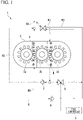
FIG. 1 is a schematic diagram illustrating a pump system according to an embodiment of the present disclosure. -
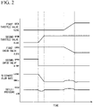
FIG. 2 is a time chart describing a degree of valve opening, a discharge flow rate, and an outlet pressure of the pump system according to the embodiment of the present disclosure. - An embodiment of a pump system according to the present disclosure will be described below with reference to the drawings.
- As illustrated in
FIG. 1 , apump system 1 according to the embodiment is, for example, a device which pressurizes liquid fuel (a fluid) and includes acasing 2, threegears pump system 1, liquid fuel guided from outside through the supply flow path R is pressurized and discharged through the outlet flow path R4. - The
casing 2 is a container having the threegears casing 2, a volume chamber in which liquid fuel is pressurized is formed in a first pressure-increasing portion A and a second pressure-increasing portion B which will be described later. - The
gears fuel controller 8. The power may be derived, for example, from an output shaft of an electric motor, a turbine connected to thepump system 1, or the like. Thegear 3b meshes with thegear 3a and thegear 3c. That is to say, the triple-gear pump is constituted by the first pressure-increasing portion A in the present disclosure using thegear 3a and thegear 3b and the second pressure-increasing portion B in the present disclosure using thegear 3b and thegear 3c. Such a first pressure-increasing portion A is connected to a branch flow path R5 which branches from the supply flow path R and is connected to the outlet flow path R4 on the outlet side of the first pressure-increasing portion A. Moreover, the second pressure-increasing portion B is connected to the first flow path R1 on the inlet side of the second pressure-increasing portion B and is connected to the second flow path R2 on the outlet side of the second pressure-increasing portion B. - Also, the first flow path R1 is connected to the outlet flow path R4.
Furthermore, a downstream end portion of the second flow path R2 is connected to the outlet flow path R4. In addition, the third flow path R3 is connected to the supply flow path R, the first flow path R1, and an upstream of the second flow path R2. That is to say, the first pressure-increasing portion A and the second pressure-increasing portion B are connected in series through the first flow path R1 and the second flow path R2. Moreover, the first pressure-increasing portion A and the second pressure-increasing portion B are connected in parallel through the first flow path R1 and the third flow path R3 . - The first throttle valve 4 is provided in the first flow path R1 and thereby it is possible to change a flow rate of liquid fuel flowing from the first pressure-increasing portion A to the second pressure-increasing portion B.
- The
second throttle valve 5 is provided in the vicinity of an end in the third flow path R3 on a side connected to the second flow path R2 and thereby it is possible to change an amount of liquid fuel discharged from the second pressure-increasing portion B and flowing into the third flow path R3. Furthermore, the first throttle valve 4 and thesecond throttle valve 5 are electric valves and are controlled by thefuel controller 8. - The first check valve 6 is provided in the supply flow path R, is driven due to a differential pressure between liquid fuel upstream of the first check valve 6 and the liquid fuel downstream of the first check valve 6 (the liquid fuel in the third flow path R3) in the supply flow path R, and blocks the inflow of the liquid fuel from the third flow path R3 to the supply flow path R.
- The
second check valve 7 is provided in the second flow path R2, is driven due to a differential pressure between the liquid fuel upstream of thesecond check valve 7 and the liquid fuel downstream of the second check valve 7 (the liquid fuel in the outlet flow path R4 side) in the second flow path R2, and blocks the inflow of the liquid fuel from the outlet flow path R4 toward the second pressure-increasing portion B. - The
fuel controller 8 may include a central processing unit (CPU), a memory such as a random-access memory (RAM) and a read-only memory (ROM), a storage device such as a hard disk drive (HDD) and a solid-state drive (SSD), and an input/output device. - In such a
pump system 1, when the first pressure-increasing portion A and the second pressure-increasing portion B are connected in a parallel state, the first throttle valve 4 and thesecond throttle valve 5 are closed. In the parallel state, fuel which has passed through the supply flow path R is guided to the first pressure-increasing portion A and the third flow path R3. Fuel which has passed through the third flow path R3 is supplied to the second pressure-increasing portion B. Thus, the liquid fuel which has passed through the supply flow path R is directly supplied to the first pressure-increasing portion A and the second pressure-increasing portion B. Furthermore, the liquid fuel pressurized in the first pressure-increasing portion A is guided to the outlet flow path R4. In addition, the liquid fuel pressurized in the second pressure-increasing portion B is guided to the outlet flow path R4 via the second flow path R2. - As illustrated in
FIG. 2 , when the first pressure-increasing portion A and the second pressure-increasing portion B change to a series state (are switched from a parallel state to a series state), first, thesecond throttle valve 5 is gradually opened by thefuel controller 8 and the liquid fuel in the second flow path R2 is pressurized accordingly. Thus, thesecond check valve 7 is closed. Therefore, the liquid fuel discharged from the second pressure-increasing portion B gradually flows into the third flow path R3. At this time, since the flow rate in which the liquid fuel flows into the second pressure-increasing portion B is larger than the flow rate in which the liquid fuel is discharged from the second pressure-increasing portion B, the liquid fuel is not pressurized in the flow paths upstream of the second pressure-increasing portion B (the first flow path R1 and the third flow path R3). Thesecond throttle valve 5 is gradually opened over about 1 second. Through such an operation, the discharge flow rate of thepump system 1 is halved. Furthermore, the pressure on the outlet side (an outlet pressure and the pressure of the liquid fuel in the outlet flow path R4) slightly decreases due to pulsation and then returns to the original pressure. - Also, when the
fuel controller 8 causes the first throttle valve 4 to gradually open, the liquid fuel discharged from the first pressure-increasing portion A flows into the first flow path R1. Thus, the flow rate flowing into the second pressure-increasing portion B gradually increases and the liquid fuel of the flow paths upstream of the second pressure-increasing portion B (the first flow path R1 and the third flow path R3) is pressurized. Therefore, in the supply flow path R connected to the third flow path R3, the pressure of the liquid fuel downstream of the first check valve 6 becomes larger than the pressure of the liquid fuel upstream of the first check valve 6. Thus, the first check valve 6 is closed. As a result, the inflow of the liquid fuel into the second pressure-increasing portion B via the third flow path R3 stops. Through such an operation, the discharge flow rate of thepump system 1 is slightly increased due to pulsation when the first throttle valve 4 is opened and returns to the original discharge flow rate. Similarly, the outlet pressure also increases slightly and returns to the original pressure. - If the first throttle valve 4 is fully opened, the pressure of the liquid fuel in the third flow path R3 becomes equal to the pressure of the liquid fuel in the first flow path R1. Thus, the inflow of the liquid fuel from the first flow path R1 to the third flow path R3 stops. Therefore, the first pressure-increasing portion A and the second pressure-increasing portion B change to a series state. That is to say, the liquid fuel discharged from the first pressure-increasing portion A passes through the first flow path R1 and flows into the second pressure-increasing portion B and is discharged through the outlet flow path R4. As a result, the
pump system 1 is changed from a parallel state to a series state. At this time, since the liquid fuel has the same flow rate upstream and downstream of the second pressure-increasing portion B, the pressure of the liquid fuel does not increase in the second pressure-increasing portion B. - Such a series of switching operations is performed in about 2 seconds. Furthermore, when the switching from a series state to a parallel state is performed, the
pump system 1 operates each valve in the reverse order of the above. - According to the embodiment, when the
pump system 1 is changed from the parallel state to the series state, it is possible to gently pressurize the liquid fuel flowing into the second pressure-increasing portion B by gradually opening the first throttle valve 4 after all the other valve operations. Therefore, it is possible to perform the switching to the series state in a short time and it is possible to minimize sudden pressure pulsation in the outlet flow path R4. It is also possible to make the pressure pulsation smaller by sufficiently lengthening a valve opening time of thesecond throttle valve 5 and the first throttle valve 4. - Also, according to the embodiment, the
pump system 1 includes thesecond check valve 7 as a second valve device. Thus, it is possible to drive the second valve device due to the differential pressure (the differential pressure between upstream and downstream of the second valve device) without an operation using the control device. Therefore, the control by thefuel controller 8 is simple and easy. - Furthermore, according to the embodiment, the
pump system 1 opens the first throttle valve 4 after thesecond throttle valve 5 is closed. Thus, the liquid fuel in the third flow path R3 is gently pressurized with the opening of the first throttle valve 4. Therefore, it is possible to perform the switching to the series state in a short time and it is possible to minimize sudden pressure pulsation in the outlet flow path R4. - Similarly, also when the switching from a series state to a parallel state is performed, it is possible to minimize pressure pulsation in the outlet flow path R4 when the switching from the series state to the parallel state is performed by closing the
second throttle valve 5 after the first throttle valve 4 is closed. - Although the preferred embodiments of the present disclosure have been described above with reference to the drawings, the present disclosure is not limited to the above embodiments. The various shapes and combinations of the constituent members shown in the above embodiments are examples and can be variously changed within the scope of the present disclosure based on design requirements and the like.
- Although a device including the
second check valve 7 is described in the above embodiments, the present disclosure is not limited thereto. Instead of thesecond check valve 7, a throttle valve may be provided at the same position as thesecond check valve 7. In this case, the throttle valve is closed by thefuel controller 8 when the switching from a parallel state to a series state is performed. - Also, although the
pump system 1 is a device which pressurizes liquid fuel as a fluid in the above embodiments, the present disclosure is not limited thereto. Thepump system 1 may be a device which pressurizes other liquids. - The present disclosure can be applied to a pump system including a triple-gear pump which pressurizes a fluid using three gears.
-
- 1
- pump system
- 2
- casing
- 3a
- gear
- 3b
- gear
- 3c
- gear
- 4
- first throttle valve (first valve device)
- 5
- second throttle valve (third valve device)
- 6
- first check valve
- 7
- second check valve (second valve device)
- 8
- fuel controller (control device)
- A
- first pressure-increasing portion
- B
- second pressure-increasing portion
- R
- supply flow path
- R1
- first flow path
- R2
- second flow path
- R3
- third flow path
- R4
- outlet flow path
- R5
- branch flow path
Claims (4)
- A pump system comprising:a triple-gear pump which pressurizes a fluid using three gears;an outlet flow path which guides the fluid from a first pressure-increasing portion to an outlet;a first flow path which guides the fluid from the first pressure-increasing portion to a second pressure-increasing portion;a second flow path which guides the fluid from the second pressure-increasing portion to the outlet flow path;a third flow path connected to the first flow path and the second flow path;a first valve device provided in the first flow path;a second valve device provided in the second flow path; anda control device which controls the first valve device,wherein, when the first pressure-increasing portion and the second pressure-increasing portion are switched from a parallel state to a series state, the control device causes the first valve device to open after the second valve device is closed.
- The pump system according to claim 1, wherein the second valve device is a check valve which blocks an inflow of the fluid from the outlet flow path toward the second pressure-increasing portion.
- The pump system according to claim 1 or 2, comprising:a third valve device provided in the third flow path and controlled by the control device,wherein, when the first pressure-increasing portion and the second pressure-increasing portion are switched from the parallel state to the series state, the control device causes the third valve device to open before the first valve device is opened.
- The pump system according to any one of claims 1 to 3, comprising:a fluid supply flow path connected to the first pressure-increasing portion and the third flow path and configured to supply the fluid from outside; anda check valve provided in the fluid supply flow path.
Applications Claiming Priority (2)
| Application Number | Priority Date | Filing Date | Title |
|---|---|---|---|
| JP2019108643 | 2019-06-11 | ||
| PCT/JP2020/022101 WO2020250796A1 (en) | 2019-06-11 | 2020-06-04 | Pump system |
Publications (3)
| Publication Number | Publication Date |
|---|---|
| EP3985255A1 true EP3985255A1 (en) | 2022-04-20 |
| EP3985255A4 EP3985255A4 (en) | 2023-06-28 |
| EP3985255B1 EP3985255B1 (en) | 2025-08-06 |
Family
ID=73780746
Family Applications (1)
| Application Number | Title | Priority Date | Filing Date |
|---|---|---|---|
| EP20822821.3A Active EP3985255B1 (en) | 2019-06-11 | 2020-06-04 | Pump system |
Country Status (4)
| Country | Link |
|---|---|
| US (1) | US11933294B2 (en) |
| EP (1) | EP3985255B1 (en) |
| JP (1) | JP7248114B2 (en) |
| WO (1) | WO2020250796A1 (en) |
Cited By (1)
| Publication number | Priority date | Publication date | Assignee | Title |
|---|---|---|---|---|
| EP4567277A4 (en) * | 2022-08-04 | 2026-04-22 | Ihi Corp | Triple-gear pump |
Family Cites Families (9)
| Publication number | Priority date | Publication date | Assignee | Title |
|---|---|---|---|---|
| JP4206646B2 (en) | 2001-04-04 | 2009-01-14 | 株式会社Ihi | Fuel supply method and fuel supply system for gas turbine engine, and gas turbine engine |
| JP4065721B2 (en) * | 2002-05-14 | 2008-03-26 | 社団法人日本航空宇宙工業会 | Double gear pump and switching circuit for serial / parallel switching |
| JP4144343B2 (en) * | 2002-12-16 | 2008-09-03 | 株式会社Ihi | Fluid supply system |
| JP5104656B2 (en) | 2008-08-26 | 2012-12-19 | 株式会社豊田自動織機 | Variable displacement rotary pump |
| US8793971B2 (en) | 2010-05-25 | 2014-08-05 | Hamilton Sundstrand Corporation | Fuel pumping system for a gas turbine engine |
| JP5903766B2 (en) | 2011-03-17 | 2016-04-13 | 株式会社Ihi | Fuel supply device |
| JP5983419B2 (en) | 2013-01-18 | 2016-08-31 | 株式会社Ihi | Fuel system |
| WO2017009994A1 (en) | 2015-07-16 | 2017-01-19 | 株式会社Ihi | Triple gear pump and fluid supplying device |
| JP2019108643A (en) | 2017-12-20 | 2019-07-04 | セイコーエプソン株式会社 | Sheet processing apparatus and sheet processing method |
-
2020
- 2020-06-04 WO PCT/JP2020/022101 patent/WO2020250796A1/en not_active Ceased
- 2020-06-04 EP EP20822821.3A patent/EP3985255B1/en active Active
- 2020-06-04 US US17/617,197 patent/US11933294B2/en active Active
- 2020-06-04 JP JP2021526049A patent/JP7248114B2/en active Active
Cited By (1)
| Publication number | Priority date | Publication date | Assignee | Title |
|---|---|---|---|---|
| EP4567277A4 (en) * | 2022-08-04 | 2026-04-22 | Ihi Corp | Triple-gear pump |
Also Published As
| Publication number | Publication date |
|---|---|
| US11933294B2 (en) | 2024-03-19 |
| WO2020250796A1 (en) | 2020-12-17 |
| EP3985255A4 (en) | 2023-06-28 |
| EP3985255B1 (en) | 2025-08-06 |
| US20220235767A1 (en) | 2022-07-28 |
| JPWO2020250796A1 (en) | 2021-10-21 |
| JP7248114B2 (en) | 2023-03-29 |
Similar Documents
| Publication | Publication Date | Title |
|---|---|---|
| KR101773273B1 (en) | Hydraulic device and prime mover device | |
| JP2017166401A (en) | Multistage compressor | |
| EP2947297B1 (en) | Fuel system | |
| FI3857070T3 (en) | Oil-injected multistage compressor device and method for controlling such a compressor device | |
| US11933294B2 (en) | Pump system | |
| WO2012073693A1 (en) | Reverse osmosis membrane separator, start-up method therefor, and method for producing permeate | |
| KR101440026B1 (en) | Multi stage compression apparatus having anti-surge-logic | |
| CN205117564U (en) | Fuel injection system and low pressure oil circuit thereof | |
| RU2016103032A (en) | HYDRAULIC MACHINE SYSTEM AND MACHINE | |
| CN105351188B (en) | A kind of two grades of variable displacement vane pump control systems of combination valve type | |
| EP3569870B1 (en) | Energy recovery device and energy recovery method | |
| EP3845761A1 (en) | Fluid supply system | |
| JP2001113136A (en) | Reverse osmosis treatment apparatus and desalination method | |
| US20110225962A1 (en) | Variable Speed Hydraulic Pump Apparatus and Method | |
| EP4495425A1 (en) | Combined high pressure relief and bypass valves | |
| US20230228473A1 (en) | Water purifier | |
| CN112901578A (en) | Valve, hydraulic system, construction machine, and movable valve element | |
| US20160097404A1 (en) | Bidirectional Output Mixed Hydraulic Power System | |
| RU126375U1 (en) | FUEL COMPONENT FEEDING DEVICE FOR LIQUID ROCKET ENGINE WITH DEEP THROTTLE | |
| US9951771B2 (en) | Selectable flow hydraulic gear pump | |
| RU153810U1 (en) | DEVICE FOR REGULATING VEHICLE PUMP PERFORMANCE | |
| CN111344494A (en) | Oil pressure control valve | |
| RU2343319C2 (en) | Method of pump station startup to run mode | |
| CN112780569A (en) | Two-stage centrifugal pump | |
| JP3030747B2 (en) | Small hydro power plant |
Legal Events
| Date | Code | Title | Description |
|---|---|---|---|
| STAA | Information on the status of an ep patent application or granted ep patent |
Free format text: STATUS: THE INTERNATIONAL PUBLICATION HAS BEEN MADE |
|
| PUAI | Public reference made under article 153(3) epc to a published international application that has entered the european phase |
Free format text: ORIGINAL CODE: 0009012 |
|
| STAA | Information on the status of an ep patent application or granted ep patent |
Free format text: STATUS: REQUEST FOR EXAMINATION WAS MADE |
|
| 17P | Request for examination filed |
Effective date: 20220111 |
|
| AK | Designated contracting states |
Kind code of ref document: A1 Designated state(s): AL AT BE BG CH CY CZ DE DK EE ES FI FR GB GR HR HU IE IS IT LI LT LU LV MC MK MT NL NO PL PT RO RS SE SI SK SM TR |
|
| DAV | Request for validation of the european patent (deleted) | ||
| DAX | Request for extension of the european patent (deleted) | ||
| REG | Reference to a national code |
Ref country code: DE Ref legal event code: R079 Free format text: PREVIOUS MAIN CLASS: F04C0014260000 Ipc: F04C0014020000 Ref country code: DE Ref legal event code: R079 Ref document number: 602020056099 Country of ref document: DE Free format text: PREVIOUS MAIN CLASS: F04C0014260000 Ipc: F04C0014020000 |
|
| A4 | Supplementary search report drawn up and despatched |
Effective date: 20230531 |
|
| RIC1 | Information provided on ipc code assigned before grant |
Ipc: F04C 2/14 20060101ALI20230524BHEP Ipc: F04C 14/02 20060101AFI20230524BHEP |
|
| GRAP | Despatch of communication of intention to grant a patent |
Free format text: ORIGINAL CODE: EPIDOSNIGR1 |
|
| STAA | Information on the status of an ep patent application or granted ep patent |
Free format text: STATUS: GRANT OF PATENT IS INTENDED |
|
| INTG | Intention to grant announced |
Effective date: 20250320 |
|
| GRAS | Grant fee paid |
Free format text: ORIGINAL CODE: EPIDOSNIGR3 |
|
| GRAA | (expected) grant |
Free format text: ORIGINAL CODE: 0009210 |
|
| STAA | Information on the status of an ep patent application or granted ep patent |
Free format text: STATUS: THE PATENT HAS BEEN GRANTED |
|
| AK | Designated contracting states |
Kind code of ref document: B1 Designated state(s): AL AT BE BG CH CY CZ DE DK EE ES FI FR GB GR HR HU IE IS IT LI LT LU LV MC MK MT NL NO PL PT RO RS SE SI SK SM TR |
|
| REG | Reference to a national code |
Ref country code: GB Ref legal event code: FG4D |
|
| REG | Reference to a national code |
Ref country code: CH Ref legal event code: EP |
|
| REG | Reference to a national code |
Ref country code: IE Ref legal event code: FG4D |
|
| REG | Reference to a national code |
Ref country code: DE Ref legal event code: R096 Ref document number: 602020056099 Country of ref document: DE |
|
| REG | Reference to a national code |
Ref country code: NL Ref legal event code: MP Effective date: 20250806 |
|
| PG25 | Lapsed in a contracting state [announced via postgrant information from national office to epo] |
Ref country code: IS Free format text: LAPSE BECAUSE OF FAILURE TO SUBMIT A TRANSLATION OF THE DESCRIPTION OR TO PAY THE FEE WITHIN THE PRESCRIBED TIME-LIMIT Effective date: 20251206 |
|
| PG25 | Lapsed in a contracting state [announced via postgrant information from national office to epo] |
Ref country code: NO Free format text: LAPSE BECAUSE OF FAILURE TO SUBMIT A TRANSLATION OF THE DESCRIPTION OR TO PAY THE FEE WITHIN THE PRESCRIBED TIME-LIMIT Effective date: 20251106 |
|
| REG | Reference to a national code |
Ref country code: LT Ref legal event code: MG9D |
|
| PG25 | Lapsed in a contracting state [announced via postgrant information from national office to epo] |
Ref country code: PT Free format text: LAPSE BECAUSE OF FAILURE TO SUBMIT A TRANSLATION OF THE DESCRIPTION OR TO PAY THE FEE WITHIN THE PRESCRIBED TIME-LIMIT Effective date: 20251209 |
|
| PG25 | Lapsed in a contracting state [announced via postgrant information from national office to epo] |
Ref country code: FI Free format text: LAPSE BECAUSE OF FAILURE TO SUBMIT A TRANSLATION OF THE DESCRIPTION OR TO PAY THE FEE WITHIN THE PRESCRIBED TIME-LIMIT Effective date: 20250806 |
|
| PG25 | Lapsed in a contracting state [announced via postgrant information from national office to epo] |
Ref country code: HR Free format text: LAPSE BECAUSE OF FAILURE TO SUBMIT A TRANSLATION OF THE DESCRIPTION OR TO PAY THE FEE WITHIN THE PRESCRIBED TIME-LIMIT Effective date: 20250806 Ref country code: NL Free format text: LAPSE BECAUSE OF FAILURE TO SUBMIT A TRANSLATION OF THE DESCRIPTION OR TO PAY THE FEE WITHIN THE PRESCRIBED TIME-LIMIT Effective date: 20250806 |
|
| PG25 | Lapsed in a contracting state [announced via postgrant information from national office to epo] |
Ref country code: GR Free format text: LAPSE BECAUSE OF FAILURE TO SUBMIT A TRANSLATION OF THE DESCRIPTION OR TO PAY THE FEE WITHIN THE PRESCRIBED TIME-LIMIT Effective date: 20251107 |
|
| PG25 | Lapsed in a contracting state [announced via postgrant information from national office to epo] |
Ref country code: SE Free format text: LAPSE BECAUSE OF FAILURE TO SUBMIT A TRANSLATION OF THE DESCRIPTION OR TO PAY THE FEE WITHIN THE PRESCRIBED TIME-LIMIT Effective date: 20250806 |
|
| PG25 | Lapsed in a contracting state [announced via postgrant information from national office to epo] |
Ref country code: LV Free format text: LAPSE BECAUSE OF FAILURE TO SUBMIT A TRANSLATION OF THE DESCRIPTION OR TO PAY THE FEE WITHIN THE PRESCRIBED TIME-LIMIT Effective date: 20250806 |
|
| PG25 | Lapsed in a contracting state [announced via postgrant information from national office to epo] |
Ref country code: PL Free format text: LAPSE BECAUSE OF FAILURE TO SUBMIT A TRANSLATION OF THE DESCRIPTION OR TO PAY THE FEE WITHIN THE PRESCRIBED TIME-LIMIT Effective date: 20250806 Ref country code: BG Free format text: LAPSE BECAUSE OF FAILURE TO SUBMIT A TRANSLATION OF THE DESCRIPTION OR TO PAY THE FEE WITHIN THE PRESCRIBED TIME-LIMIT Effective date: 20250806 |
|
| PG25 | Lapsed in a contracting state [announced via postgrant information from national office to epo] |
Ref country code: RS Free format text: LAPSE BECAUSE OF FAILURE TO SUBMIT A TRANSLATION OF THE DESCRIPTION OR TO PAY THE FEE WITHIN THE PRESCRIBED TIME-LIMIT Effective date: 20251106 |
|
| PG25 | Lapsed in a contracting state [announced via postgrant information from national office to epo] |
Ref country code: ES Free format text: LAPSE BECAUSE OF FAILURE TO SUBMIT A TRANSLATION OF THE DESCRIPTION OR TO PAY THE FEE WITHIN THE PRESCRIBED TIME-LIMIT Effective date: 20250806 |
|
| REG | Reference to a national code |
Ref country code: AT Ref legal event code: MK05 Ref document number: 1822104 Country of ref document: AT Kind code of ref document: T Effective date: 20250806 |
|
| PG25 | Lapsed in a contracting state [announced via postgrant information from national office to epo] |
Ref country code: SM Free format text: LAPSE BECAUSE OF FAILURE TO SUBMIT A TRANSLATION OF THE DESCRIPTION OR TO PAY THE FEE WITHIN THE PRESCRIBED TIME-LIMIT Effective date: 20250806 |
|
| PG25 | Lapsed in a contracting state [announced via postgrant information from national office to epo] |
Ref country code: DK Free format text: LAPSE BECAUSE OF FAILURE TO SUBMIT A TRANSLATION OF THE DESCRIPTION OR TO PAY THE FEE WITHIN THE PRESCRIBED TIME-LIMIT Effective date: 20250806 |
|
| PG25 | Lapsed in a contracting state [announced via postgrant information from national office to epo] |
Ref country code: AT Free format text: LAPSE BECAUSE OF FAILURE TO SUBMIT A TRANSLATION OF THE DESCRIPTION OR TO PAY THE FEE WITHIN THE PRESCRIBED TIME-LIMIT Effective date: 20250806 |
|
| PG25 | Lapsed in a contracting state [announced via postgrant information from national office to epo] |
Ref country code: IT Free format text: LAPSE BECAUSE OF FAILURE TO SUBMIT A TRANSLATION OF THE DESCRIPTION OR TO PAY THE FEE WITHIN THE PRESCRIBED TIME-LIMIT Effective date: 20250806 |
|
| PG25 | Lapsed in a contracting state [announced via postgrant information from national office to epo] |
Ref country code: CZ Free format text: LAPSE BECAUSE OF FAILURE TO SUBMIT A TRANSLATION OF THE DESCRIPTION OR TO PAY THE FEE WITHIN THE PRESCRIBED TIME-LIMIT Effective date: 20250806 |
|
| PG25 | Lapsed in a contracting state [announced via postgrant information from national office to epo] |
Ref country code: EE Free format text: LAPSE BECAUSE OF FAILURE TO SUBMIT A TRANSLATION OF THE DESCRIPTION OR TO PAY THE FEE WITHIN THE PRESCRIBED TIME-LIMIT Effective date: 20250806 Ref country code: SK Free format text: LAPSE BECAUSE OF FAILURE TO SUBMIT A TRANSLATION OF THE DESCRIPTION OR TO PAY THE FEE WITHIN THE PRESCRIBED TIME-LIMIT Effective date: 20250806 |