EP3984886B1 - Wing structure and attachment to frame for unmanned aerial vehicles - Google Patents
Wing structure and attachment to frame for unmanned aerial vehicles Download PDFInfo
- Publication number
- EP3984886B1 EP3984886B1 EP21211830.1A EP21211830A EP3984886B1 EP 3984886 B1 EP3984886 B1 EP 3984886B1 EP 21211830 A EP21211830 A EP 21211830A EP 3984886 B1 EP3984886 B1 EP 3984886B1
- Authority
- EP
- European Patent Office
- Prior art keywords
- wing
- attaching
- shell
- boom
- frame
- Prior art date
- Legal status (The legal status is an assumption and is not a legal conclusion. Google has not performed a legal analysis and makes no representation as to the accuracy of the status listed.)
- Active
Links
Images





Classifications
-
- B—PERFORMING OPERATIONS; TRANSPORTING
- B64—AIRCRAFT; AVIATION; COSMONAUTICS
- B64U—UNMANNED AERIAL VEHICLES [UAV]; EQUIPMENT THEREFOR
- B64U10/00—Type of UAV
- B64U10/25—Fixed-wing aircraft
-
- B—PERFORMING OPERATIONS; TRANSPORTING
- B64—AIRCRAFT; AVIATION; COSMONAUTICS
- B64U—UNMANNED AERIAL VEHICLES [UAV]; EQUIPMENT THEREFOR
- B64U30/00—Means for producing lift; Empennages; Arrangements thereof
- B64U30/10—Wings
-
- B—PERFORMING OPERATIONS; TRANSPORTING
- B64—AIRCRAFT; AVIATION; COSMONAUTICS
- B64U—UNMANNED AERIAL VEHICLES [UAV]; EQUIPMENT THEREFOR
- B64U50/00—Propulsion; Power supply
- B64U50/10—Propulsion
- B64U50/13—Propulsion using external fans or propellers
-
- B—PERFORMING OPERATIONS; TRANSPORTING
- B64—AIRCRAFT; AVIATION; COSMONAUTICS
- B64C—AEROPLANES; HELICOPTERS
- B64C2211/00—Modular constructions of airplanes or helicopters
-
- B—PERFORMING OPERATIONS; TRANSPORTING
- B64—AIRCRAFT; AVIATION; COSMONAUTICS
- B64C—AEROPLANES; HELICOPTERS
- B64C27/00—Rotorcraft; Rotors peculiar thereto
- B64C27/22—Compound rotorcraft, i.e. aircraft using in flight the features of both aeroplane and rotorcraft
-
- B—PERFORMING OPERATIONS; TRANSPORTING
- B64—AIRCRAFT; AVIATION; COSMONAUTICS
- B64C—AEROPLANES; HELICOPTERS
- B64C3/00—Wings
- B64C3/18—Spars; Ribs; Stringers
- B64C3/185—Spars
-
- B—PERFORMING OPERATIONS; TRANSPORTING
- B64—AIRCRAFT; AVIATION; COSMONAUTICS
- B64C—AEROPLANES; HELICOPTERS
- B64C3/00—Wings
- B64C3/26—Construction, shape, or attachment of separate skins, e.g. panels
-
- B—PERFORMING OPERATIONS; TRANSPORTING
- B64—AIRCRAFT; AVIATION; COSMONAUTICS
- B64U—UNMANNED AERIAL VEHICLES [UAV]; EQUIPMENT THEREFOR
- B64U20/00—Constructional aspects of UAVs
- B64U20/90—Cooling
- B64U20/92—Cooling of avionics
Definitions
- An unmanned vehicle which may also be referred to as an autonomous vehicle, is a vehicle capable of travel without a physically-present human operator on board.
- An unmanned vehicle may operate in a remote-control mode, in an autonomous mode, or in a partially autonomous mode.
- an unmanned vehicle When an unmanned vehicle operates in a remote-control mode, a pilot or driver that is at a remote location can control the unmanned vehicle by commands that are sent to the unmanned vehicle via a wireless link.
- the unmanned vehicle When the unmanned vehicle operates in autonomous mode, the unmanned vehicle typically moves based on pre-programmed navigation waypoints, dynamic automation systems, or a combination of these. Further, some unmanned vehicles can operate in both a remote-control mode and an autonomous mode, and in some instances may do so simultaneously. For instance, a remote pilot or driver may wish to leave navigation to an autonomous system while manually performing another task, such as operating a mechanical system for picking up objects, as an example.
- unmanned vehicles may operate in the air, on the ground, underwater, or in space. Examples include quad-copters and tail-sitter unmanned aerial vehicles (UAVs), among others. Some unmanned vehicles operate in multi-environment operation. Examples of such hybrid unmanned vehicles include an amphibious craft that is capable of operation on land as well as on water, or a floatplane that is capable of landing on water as well as on land. Other examples are also possible.
- UAVs unmanned aerial vehicles
- Some unmanned vehicles operate in multi-environment operation. Examples of such hybrid unmanned vehicles include an amphibious craft that is capable of operation on land as well as on water, or a floatplane that is capable of landing on water as well as on land. Other examples are also possible.
- WO 2017/066748 A1 describes a fixed wing UAV.
- Some conventional UAVs include an inner structural frame and an outer shell.
- the structural frame is built using a relatively strong, but also relatively heavy material (e.g., steel, aluminum, hard plastic, etc.), while the outer shell is made of a lighter filler material (e.g., closed cell foam or other light polymer).
- the structural frame is surrounded by the outer shell material.
- the structural frame is assembled or manufactured first.
- the outer shell e.g., closed cell foam
- the excess outer shell material is cut away to make room for cables, engines, avionics, and other subassemblies.
- removing the excess outer shell material may be difficult and time consuming, thus decreasing the efficiency of the overall UAV manufacturing process.
- the material of the frame and the material of the outer shell may have different coefficients of thermal expansion (CTE).
- CTE coefficients of thermal expansion
- a wing spar and a boom carrier are assembled to form a structural H-frame.
- the wing spar and the boom carrier may be tubes made of, for example, carbon fiber, hard plastic, aluminum, or metal alloys.
- the wing spar and the boom carrier may have pre-drilled holes for the subsequent attachment of motor mounts.
- a wing shell and boom shells may be attached to the H-frame by adhesive elements (e.g., adhesive tape, double-sided adhesive tape, glue, etc.). Therefore, multiple shells are attached to the H-frame instead of having a monolithic body sprayed onto the H-frame as in the prior art.
- the presence of the multiple shells reduces the CTE-induced stresses of the structural frame of the UAV. As a result, the UAV may have better dimensional accuracy and/or improved reliability.
- the same H-frame may be used with the wing shell and/or boom shells having different size and/or design, therefore improving the modularity and versatility of the UAV designs.
- a fuselage of the UAV may also be modular/interchangeable.
- the wing shell and/or the boom shells may be made of relatively light polymers (e.g., closed cell foam) covered by the harder, but relatively thin, plastic skins.
- UAV subsystems may be tested before the assembly of the UAV is completed.
- components of the fuselage e.g., avionics, battery unit, delivery units
- the motors and the electronics of printed circuit boards (PCBs) may also be electrically tested before the final assembly.
- PCBs printed circuit boards
- FIGURE 1 is an isometric view of a UAV 1000 in accordance with an embodiment of the present technology.
- the UAV 1000 includes a wing 110, booms 210, and a fuselage 310.
- the wing 110 carries horizontal propulsion units 140
- the booms 210 carry vertical propulsion units 240.
- power for the propulsion units may be provided from a battery compartment 310-1 of the fuselage 310.
- the fuselage 310 also includes an avionics compartment 310-1, an additional battery compartment (not shown) and/or a delivery unit 310-2 for handling the payload.
- the booms 210 terminate in rudders 230 for improved yaw control of the UAV 1000.
- the wings 110 may terminate in wing tips 111 for improved control of lift of the UAV.
- the illustrated UAV 1000 includes a structural frame. Some embodiments of the structural frame are discussed with reference to Figure 2 below.
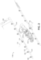
- FIGURE 2 is an isometric view of a structural frame 1100 (also referred to as a "structural H-frame” or an "H-frame”) of a UAV in accordance with an embodiment of the present technology.
- the H-frame 1100 includes a wing spar 112 and boom carriers 212.
- the wing spar 112 and the boom carriers 212 may be made of carbon fiber, hard plastic, aluminum, light metal alloys, or other materials.
- the wing spar 112 and the boom carriers 212 may be connected with clamps 114.
- the wing spar 112 may include predrilled holes 145 for horizontal propulsion units, and the boom carriers 212 may include predrilled holes (hidden by motor mounts 242 in this view) for vertical propulsion units.
- the fuselage 310 is removeably attached to the H-frame (e.g., attached to the wing spar 112 by clamps 114).
- the removable attachment of the fuselage 310 may improve quality and or modularity of the UAV.
- electrical/mechanical components of the fuselage 310 may be tested before attaching the fuselage 310 to the H-frame and/or before attaching PCBs 214 to the boom carriers 212, therefore eliminating defective parts/subassemblies prior to completing the UAV.
- different types/models of the fuselage 310 may be attached to the H-frame, therefore improving the modularity of the design. The electrical cabling and routing of the PCBs is discussed with reference to Figure 3 below.
- FIGURE 3 is an isometric view of cable routing of a UAV in accordance with an embodiment of the present technology.
- the power and/or control signals from the fuselage 310 may be routed through cables 214-2 to PCBs 214.
- the UAV has four PCBs, but other numbers of PCBs are also possible.
- the UAV may include two PCBs, one per the boom.
- the PCBs carry electronic components 214-1, for example, power converters, controllers, memory, passive components, etc.
- the propulsion units of the UAV are electrically connected to the PCBs.
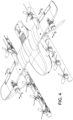
- FIGURE 4 is a partial isometric view of a UAV in accordance with an embodiment of the present technology.
- Figure 4 includes cross-sections 5-5, 6-6, and 7-7. The individual cross-sections are discussed with reference to Figures 5-7 below.
- FIGURE 5 is a cross-sectional view 5-5 of the UAV shown in Figure 4 .
- motor mounts 142 include a two-part C-clamp having an upper segment 142-1 and a lower segment 142-2.
- the motor mounts 142 may include different types of clamps.
- the two segments of the motor mount 142 may be attached to the wing spar by a fastener 143, for example, a nut and bolt combination.
- the wing spar 112 includes pre-drilled holes for the fasteners 143.
- the horizontal propulsion unit 140 may be attached to the motor mount 142 by fasteners 144. In some embodiments, replacement of the propulsion unit is facilitated by relatively easy removal of the fasteners 144. Furthermore, the same motor mounts 142 may be suitable for different types of the horizontal propulsion units 140, thus facilitating the modularity of the UAV.
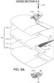
- FIGURE 5A is an exploded cross-sectional view 5-5 of the UAV shown in Figure 4 .
- the segments 142-1 and 142-2 of the motor mounts 140 may be slid over the wing skins 119-1 and 119-2; aligned with the hole 145 in the wing spar 112; and then tightened with the fastener 143 through the wing spar and clamped over the wing skins.
- the wing skins 119-1 and 119-2 may be made of hard plastic to prevent or at least minimize compression of a wing body 117, which may be made of closed cell foam or other light and relatively soft polymer.
- the upper and lower wing skins 119-1/119-2 may be connected with a wing skin clip 119-3 (e.g., structural tape, hard plastic element, metal clip, etc.).
- a wing skin clip 119-3 e.g., structural tape, hard plastic element, metal clip, etc.
- connecting the wing skins into a unitary structure improves structural integrity (e.g., a resistance against torsion) of the wing.
- forming the upper and lower portions of the wing skin, as well as a connector segment (i.e., in place of wing skin clip 119-3), as a single, unitary structure (not shown) also may improve structural integrity.
- the upper wing skin 119-1 may be pre-assembled with the wing body 117 by, for example, gluing.
- the horizontal propulsion units may be connected to their corresponding cabling using the space under the wing.
- the lower wing skin 119-2 may be attached to the wing body 117 by, for example, gluing.
- FIGURE 6 is a cross-sectional view 6-6 of the UAV shown in Figure 4 .
- the wing shell includes an aileron 116 for controlling the roll of the UAV.
- the aileron 116 may be formed by weakening the wing body 117 at the trailing edge of the wing.
- a groove 116-1 may form a flexible connection between the aileron 116 and the rest of the wing body 117.
- FIGURE 7 is a cross-sectional view 7-7 of the UAV shown in Figure 4 .
- the plane of the cross-section passes through the axis of the boom carrier 212.
- the boom carrier 212 may carry several vertical propulsion units 240 along its length.
- the cables and the PCBs (not shown) also may be added to the boom carrier prior to attaching the boom shell 218 for easier electrical routing and testing of the UAV.
- the boom shells 218 may be formed (e.g., molded) using light polymers (e.g., closed cell foam).
- the boom shells 218 may be adhesively attached to the boom carrier by adhesive elements, for example, adhesive film, adhesive tape, double-sided adhesive tape, glue, etc.
- the motor mounts 242 are preassembled onto the boom carrier 212 prior to attaching a boom shell 218 to the boom carrier.
- the vertical propulsion units 240 may be attached to the motor mounts 242 with fasteners 216, for example, the bolt and nut combination.
- holes 245 are pre-drilled through the boom carrier 212 for easier assembly.
- FIGURE 8 is an isometric view of the wing 110 in accordance with an embodiment of the present technology.
- the wing 110 is formed (e.g., molded) using light polymers (e.g., closed cell foam).
- the pre-made wing 110 may include several grooves and/or opening that eliminate or at least reduce the need to cut out the portions of the wing at the assembly time for, for example, cable routing, PCB attachment, motor mount attachment, fit with the H-frame, etc.
- the wing 110 includes grooves 124 for mating with the wing spar 112 and grooves 125 for mating with the boom carriers 212.
- the wing 110 may include notches 122 for the motor mount for the horizontal propulsion units to enable self-fixturing during assembly.
- attachment of the components and routing of the cables of the UAV requires less time and effort.
- the pre-made wings 110 having differing shapes and/or sizes may be used over the same H-frame.
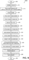
- FIGURE 9 is a flow diagram of a method of assembly in accordance with an embodiment of the present technology.
- the method may include additional steps or may be practiced without all steps illustrated in the flow chart.
- the order of the steps listed may be changed.
- the fuselage is assembled.
- the fuselage may include compartments, for example, the battery compartment, the avionics compartment, an additional battery compartment and/or the payload compartment.
- the fuselage may be electrically/mechanically tested before assembling it with the UAV.
- one compartment of the fuselage may be attached to the wing spar first, followed by attaching the remaining compartments to the already-attached compartment and/or to the spar.
- step 315 the motor mounts for the vertical propulsion units are attached to the boom carriers.
- the boom carriers may include predrilled holes for attaching the motor mounts.
- step 320 the rudders are attached to the boom carriers. Generally, the rudders improve the yaw control of the UAV.
- the wing spar and the boom carriers are connected to form the H-frame.
- the individual wing spar and/or the individual boom carrier may include several structural elements.
- the wing spar may comprise several carbon tubes for, for example, improved structural integrity.
- the fuselage is attached to the wing spar.
- the size/type of the fuselage may be selected based on, for example, type of the task that the UAV needs to perform. Such a variability of the size/type of the fuselage increases the modularity of the UAV design.
- step 335 the avionics, power supply, cable connections, etc., may be tested. As explained above, the testing of the fuselage may have already been partially or entirely performed in the earlier assembly steps.
- the PCBs may be attached to the boom carriers. Furthermore, the cables may be routed and dressed throughout the UAV.
- the wing shell may be attached to the wing spar by, for example, gluing.
- the wing shell may already include the pre-assembled upper wing skin.
- the horizontal propulsion units may be wired. In some embodiments, the horizontal propulsion units may also be tested at this step, before being attached to the wing.
- the lower wing skin may be attached to the wing shell by, for example, gluing.
- the cable routing and dressing, and attaching the PCB to the boom are at least partially completed before this step.
- the upper and lower skins may be connected by one or more wing skin clips.
- the wing skin clips improve the rigidity of the wing shell.
- a motor mount may be a two-piece C-shell that clamps on the upper and lower skins of the wing shell.
- the motor mount is attached with the wing spar with a single fastener.
- step 370 the boom shells are attached to the boom carriers. In some embodiments, by this step most or all of the cabling and PCB attachments has been completed without the boom shells standing in the way.
- the horizontal propulsion units are attached to motor mounts by, for examples, fasteners.
- the horizontal propulsion units may have already been electrically connected and tested.
- step 380 the vertical propulsion units are attached to motor mounts.
- the vertical propulsion units may have already been electrically connected and tested. The method ends in step 385.
Landscapes
- Engineering & Computer Science (AREA)
- Aviation & Aerospace Engineering (AREA)
- Mechanical Engineering (AREA)
- Chemical & Material Sciences (AREA)
- Combustion & Propulsion (AREA)
- Remote Sensing (AREA)
- Toys (AREA)
- Jib Cranes (AREA)
- Wind Motors (AREA)
Description
- An unmanned vehicle, which may also be referred to as an autonomous vehicle, is a vehicle capable of travel without a physically-present human operator on board. An unmanned vehicle may operate in a remote-control mode, in an autonomous mode, or in a partially autonomous mode.
- When an unmanned vehicle operates in a remote-control mode, a pilot or driver that is at a remote location can control the unmanned vehicle by commands that are sent to the unmanned vehicle via a wireless link. When the unmanned vehicle operates in autonomous mode, the unmanned vehicle typically moves based on pre-programmed navigation waypoints, dynamic automation systems, or a combination of these. Further, some unmanned vehicles can operate in both a remote-control mode and an autonomous mode, and in some instances may do so simultaneously. For instance, a remote pilot or driver may wish to leave navigation to an autonomous system while manually performing another task, such as operating a mechanical system for picking up objects, as an example.
- Various types of unmanned vehicles exist for different environments. For instance, unmanned vehicles may operate in the air, on the ground, underwater, or in space. Examples include quad-copters and tail-sitter unmanned aerial vehicles (UAVs), among others. Some unmanned vehicles operate in multi-environment operation. Examples of such hybrid unmanned vehicles include an amphibious craft that is capable of operation on land as well as on water, or a floatplane that is capable of landing on water as well as on land. Other examples are also possible.
WO 2017/066748 A1 describes a fixed wing UAV. - Some conventional UAVs include an inner structural frame and an outer shell. The structural frame is built using a relatively strong, but also relatively heavy material (e.g., steel, aluminum, hard plastic, etc.), while the outer shell is made of a
lighter filler material (e.g., closed cell foam or other light polymer). Typically, the structural frame is surrounded by the outer shell material. - With some conventional technologies, the structural frame is assembled or manufactured first. Next, the outer shell (e.g., closed cell foam) is sprayed onto the frame to give a shape to the UAV. The excess outer shell material is cut away to make room for cables, engines, avionics, and other subassemblies. However, in some cases removing the excess outer shell material may be difficult and time consuming, thus decreasing the efficiency of the overall UAV manufacturing process.
- Furthermore, the material of the frame and the material of the outer shell may have different coefficients of thermal expansion (CTE). As a result, the frame and the outer shell expand and contract at different rates as the temperature of the environment changes causing manufacturing and assembly defects. In time, different expansion rates may lead to bending of the frame, and, for a sufficiently high number of the temperature cycles, to material fatigue and fracturing of the frame.
- Accordingly, there remains a need for the systems and methods for assembling UAVs having improved efficiency of the assembly and reduced stress on the structural frame. Within this context, an assembling method according to claim 1 is provided.
- The foregoing aspects and many of the attendant advantages of inventive technology will become more readily appreciated as the same become better understood by reference to the following detailed description, when taken in conjunction with the accompanying drawings, wherein:
-
FIGURE 1 is an isometric view of a UAV in accordance with an embodiment of the present technology; -
FIGURE 2 is an isometric view of a frame of a UAV in accordance with an embodiment of the present technology; -
FIGURE 3 is an isometric view of cable routing of a UAV in accordance with an embodiment of the present technology; -
FIGURE 4 is a partial isometric view of a UAV in accordance with an embodiment of the present technology; -
FIGURE 5 is a cross-sectional view 5-5 of the UAV shown inFigure 4 ; -
FIGURE 5A is an exploded cross-sectional view 5-5 of the UAV shown inFigure 4 ; -
FIGURE 6 is a cross-sectional view 6-6 of the UAV shown inFigure 4 ; -
FIGURE 7 is a cross-sectional view 7-7 of the UAV shown inFigure 4 ; -
FIGURE 8 is an isometric view of a wing in accordance with an embodiment of the present technology; and -
FIGURE 9 is a flow diagram of a method of assembly in accordance with an embodiment of the present technology. - While illustrative embodiments have been described, it will be appreciated that various changes can be made therein. Briefly, the inventive technology is directed to assembling and testing UAVs. A wing spar and a boom carrier are assembled to form a structural H-frame. The wing spar and the boom carrier may be tubes made of, for example, carbon fiber, hard plastic, aluminum, or metal alloys. The wing spar and the boom carrier may have pre-drilled holes for the subsequent attachment of motor mounts.
- In some embodiments, a wing shell and boom shells may be attached to the H-frame by adhesive elements (e.g., adhesive tape, double-sided adhesive tape, glue, etc.). Therefore, multiple shells are attached to the H-frame instead of having a monolithic body sprayed onto the H-frame as in the prior art. In some embodiments, the presence of the multiple shells reduces the CTE-induced stresses of the structural frame of the UAV. As a result, the UAV may have better dimensional accuracy and/or improved reliability.
- Furthermore, in at least some embodiments, the same H-frame may be used with the wing shell and/or boom shells having different size and/or design, therefore improving the modularity and versatility of the UAV designs. Moreover, a fuselage of the UAV may also be modular/interchangeable. The wing shell and/or the boom shells may be made of relatively light polymers (e.g., closed cell foam) covered by the harder, but relatively thin, plastic skins.
- In some embodiments of the inventive technology, UAV subsystems may be tested before the assembly of the UAV is completed. For example, components of the fuselage (e.g., avionics, battery unit, delivery units) may be electrically tested before the fuselage is mounted to the H-frame. Furthermore, the motors and the electronics of printed circuit boards (PCBs) may also be electrically tested before the final assembly. Generally, the identification of the defective parts and subassemblies early in the assembly process lowers the overall cost and lead time of the UAV.
-
FIGURE 1 is an isometric view of aUAV 1000 in accordance with an embodiment of the present technology. The UAV 1000 includes awing 110,booms 210, and afuselage 310. In some embodiments, thewing 110 carrieshorizontal propulsion units 140, and thebooms 210 carryvertical propulsion units 240. In operation, power for the propulsion units may be provided from a battery compartment 310-1 of thefuselage 310. In some embodiments, thefuselage 310 also includes an avionics compartment 310-1, an additional battery compartment (not shown) and/or a delivery unit 310-2 for handling the payload. - In some embodiments, the
booms 210 terminate inrudders 230 for improved yaw control of theUAV 1000. Thewings 110 may terminate inwing tips 111 for improved control of lift of the UAV. - The illustrated
UAV 1000 includes a structural frame. Some embodiments of the structural frame are discussed with reference toFigure 2 below. -
FIGURE 2 is an isometric view of a structural frame 1100 (also referred to as a "structural H-frame" or an "H-frame") of a UAV in accordance with an embodiment of the present technology. The H-frame 1100 includes awing spar 112 andboom carriers 212. In some embodiments thewing spar 112 and theboom carriers 212 may be made of carbon fiber, hard plastic, aluminum, light metal alloys, or other materials. Thewing spar 112 and theboom carriers 212 may be connected withclamps 114. Thewing spar 112 may includepredrilled holes 145 for horizontal propulsion units, and theboom carriers 212 may include predrilled holes (hidden by motor mounts 242 in this view) for vertical propulsion units. - In some embodiments, the
fuselage 310 is removeably attached to the H-frame (e.g., attached to thewing spar 112 by clamps 114). The removable attachment of thefuselage 310 may improve quality and or modularity of the UAV. For example, electrical/mechanical components of thefuselage 310 may be tested before attaching thefuselage 310 to the H-frame and/or before attachingPCBs 214 to theboom carriers 212, therefore eliminating defective parts/subassemblies prior to completing the UAV. Furthermore, different types/models of thefuselage 310 may be attached to the H-frame, therefore improving the modularity of the design. The electrical cabling and routing of the PCBs is discussed with reference toFigure 3 below. -
FIGURE 3 is an isometric view of cable routing of a UAV in accordance with an embodiment of the present technology. The power and/or control signals from thefuselage 310 may be routed through cables 214-2 toPCBs 214. In the illustrated embodiment, the UAV has four PCBs, but other numbers of PCBs are also possible. For example, the UAV may include two PCBs, one per the boom. The PCBs carry electronic components 214-1, for example, power converters, controllers, memory, passive components, etc. In operation, the propulsion units of the UAV are electrically connected to the PCBs. -
FIGURE 4 is a partial isometric view of a UAV in accordance with an embodiment of the present technology.Figure 4 includes cross-sections 5-5, 6-6, and 7-7. The individual cross-sections are discussed with reference toFigures 5-7 below. -
FIGURE 5 is a cross-sectional view 5-5 of the UAV shown inFigure 4 . In some embodiments, motor mounts 142 include a two-part C-clamp having an upper segment 142-1 and a lower segment 142-2. In other embodiments, the motor mounts 142 may include different types of clamps. The two segments of themotor mount 142 may be attached to the wing spar by afastener 143, for example, a nut and bolt combination. In some embodiments, thewing spar 112 includes pre-drilled holes for thefasteners 143. - The
horizontal propulsion unit 140 may be attached to themotor mount 142 byfasteners 144. In some embodiments, replacement of the propulsion unit is facilitated by relatively easy removal of thefasteners 144. Furthermore, the same motor mounts 142 may be suitable for different types of thehorizontal propulsion units 140, thus facilitating the modularity of the UAV. -
FIGURE 5A is an exploded cross-sectional view 5-5 of the UAV shown inFigure 4 . During the assembly, the segments 142-1 and 142-2 of the motor mounts 140 may be slid over the wing skins 119-1 and 119-2; aligned with thehole 145 in thewing spar 112; and then tightened with thefastener 143 through the wing spar and clamped over the wing skins. In some embodiments, the wing skins 119-1 and 119-2 may be made of hard plastic to prevent or at least minimize compression of awing body 117, which may be made of closed cell foam or other light and relatively soft polymer. - The upper and lower wing skins 119-1/119-2 may be connected with a wing skin clip 119-3 (e.g., structural tape, hard plastic element, metal clip, etc.). In some embodiments, connecting the wing skins into a unitary structure improves structural integrity (e.g., a resistance against torsion) of the wing. In other embodiments, forming the upper and lower portions of the wing skin, as well as a connector segment (i.e., in place of wing skin clip 119-3), as a single, unitary structure (not shown) also may improve structural integrity.
- In some embodiments, the upper wing skin 119-1 may be pre-assembled with the
wing body 117 by, for example, gluing. After assembling thewing shell 118 with thewing spar 112, the horizontal propulsion units may be connected to their corresponding cabling using the space under the wing. Next, the lower wing skin 119-2 may be attached to thewing body 117 by, for example, gluing. -
FIGURE 6 is a cross-sectional view 6-6 of the UAV shown inFigure 4 . In some embodiments, the wing shell includes anaileron 116 for controlling the roll of the UAV. In some embodiments, theaileron 116 may be formed by weakening thewing body 117 at the trailing edge of the wing. For example, a groove 116-1 may form a flexible connection between theaileron 116 and the rest of thewing body 117. -
FIGURE 7 is a cross-sectional view 7-7 of the UAV shown inFigure 4 . The plane of the cross-section passes through the axis of theboom carrier 212. Theboom carrier 212 may carry severalvertical propulsion units 240 along its length. Furthermore, the cables and the PCBs (not shown) also may be added to the boom carrier prior to attaching theboom shell 218 for easier electrical routing and testing of the UAV. In some embodiments, theboom shells 218 may be formed (e.g., molded) using light polymers (e.g., closed cell foam). At the assembly time, theboom shells 218 may be adhesively attached to the boom carrier by adhesive elements, for example, adhesive film, adhesive tape, double-sided adhesive tape, glue, etc. - In some embodiments, the motor mounts 242 are preassembled onto the
boom carrier 212 prior to attaching aboom shell 218 to the boom carrier. Thevertical propulsion units 240 may be attached to the motor mounts 242 withfasteners 216, for example, the bolt and nut combination. In some embodiments, holes 245 are pre-drilled through theboom carrier 212 for easier assembly. -
FIGURE 8 is an isometric view of thewing 110 in accordance with an embodiment of the present technology. In some embodiments, thewing 110 is formed (e.g., molded) using light polymers (e.g., closed cell foam). Thepre-made wing 110 may include several grooves and/or opening that eliminate or at least reduce the need to cut out the portions of the wing at the assembly time for, for example, cable routing, PCB attachment, motor mount attachment, fit with the H-frame, etc. Thewing 110 includesgrooves 124 for mating with thewing spar 112 andgrooves 125 for mating with theboom carriers 212. Furthermore, thewing 110 may includenotches 122 for the motor mount for the horizontal propulsion units to enable self-fixturing during assembly. As a result, in at least some embodiments, attachment of the components and routing of the cables of the UAV requires less time and effort. In some embodiments, thepre-made wings 110 having differing shapes and/or sizes may be used over the same H-frame. -
FIGURE 9 is a flow diagram of a method of assembly in accordance with an embodiment of the present technology. In some embodiments, the method may include additional steps or may be practiced without all steps illustrated in the flow chart. Furthermore, in some embodiments, the order of the steps listed may be changed. - The method starts in
step 305, and continues to step 310. Instep 310, the fuselage is assembled. In some embodiments, the fuselage may include compartments, for example, the battery compartment, the avionics compartment, an additional battery compartment and/or the payload compartment. In some embodiments, the fuselage may be electrically/mechanically tested before assembling it with the UAV. In other embodiments, one compartment of the fuselage may be attached to the wing spar first, followed by attaching the remaining compartments to the already-attached compartment and/or to the spar. - In
step 315, the motor mounts for the vertical propulsion units are attached to the boom carriers. In some embodiments, the boom carriers may include predrilled holes for attaching the motor mounts. - In
step 320, the rudders are attached to the boom carriers. Generally, the rudders improve the yaw control of the UAV. - In
step 325, the wing spar and the boom carriers are connected to form the H-frame. In some embodiments, the individual wing spar and/or the individual boom carrier may include several structural elements. For example, the wing spar may comprise several carbon tubes for, for example, improved structural integrity. - In
step 330, the fuselage is attached to the wing spar. The size/type of the fuselage may be selected based on, for example, type of the task that the UAV needs to perform. Such a variability of the size/type of the fuselage increases the modularity of the UAV design. - In
step 335, the avionics, power supply, cable connections, etc., may be tested. As explained above, the testing of the fuselage may have already been partially or entirely performed in the earlier assembly steps. - In
step 340, the PCBs may be attached to the boom carriers. Furthermore, the cables may be routed and dressed throughout the UAV. - In
step 345, the wing shell may be attached to the wing spar by, for example, gluing. In some embodiments, the wing shell may already include the pre-assembled upper wing skin. - In
step 350, the horizontal propulsion units may be wired. In some embodiments, the horizontal propulsion units may also be tested at this step, before being attached to the wing. - In
step 355, the lower wing skin may be attached to the wing shell by, for example, gluing. In many embodiments, the cable routing and dressing, and attaching the PCB to the boom are at least partially completed before this step. - In
step 360, the upper and lower skins may be connected by one or more wing skin clips. Generally, the wing skin clips improve the rigidity of the wing shell. - In
step 365, the motor mounts for horizontal propulsion units are attached to the wing spar. In some embodiments, a motor mount may be a two-piece C-shell that clamps on the upper and lower skins of the wing shell. In some embodiments, the motor mount is attached with the wing spar with a single fastener. - In
step 370, the boom shells are attached to the boom carriers. In some embodiments, by this step most or all of the cabling and PCB attachments has been completed without the boom shells standing in the way. - In
step 375, the horizontal propulsion units are attached to motor mounts by, for examples, fasteners. In some embodiments, the horizontal propulsion units may have already been electrically connected and tested. - In
step 380, the vertical propulsion units are attached to motor mounts. In some embodiments, the vertical propulsion units may have already been electrically connected and tested. The method ends instep 385. - Many embodiments of the technology described above may take the form of computer-executable or controller-executable instructions, including routines executed by a programmable computer or controller. Those skilled in the relevant art will appreciate that the technology can be practiced on computer/controller systems other than those shown and described above. The technology can be embodied in a special-purpose computer, application specific integrated circuit (ASIC), controller or data processor that is specifically programmed, configured or constructed to perform one or more of the computer-executable instructions described above. Of course, any logic or algorithm described herein can be implemented in software or hardware, or a combination of software and hardware.
- From the foregoing, it will be appreciated that specific embodiments of the technology have been described herein for purposes of illustration, but that various modifications may be made without deviating from the disclosure. Moreover, while various advantages and features associated with certain embodiments have been described above in the context of those embodiments, other embodiments may also exhibit such advantages and/or features, and not all embodiments need necessarily exhibit such advantages and/or features to fall within the scope of the claims.
Claims (15)
- A method for assembling an Unmanned Autonomous Vehicle, UAV (1000), comprising:connecting a wing spar (112) with boom carriers (212) to form an H-frame (1100), wherein the wing spar provides first mounting locations for securing horizontal propulsion units (140), and wherein the boom carriers provide second mounting locations for securing vertical propulsion units (240);attaching a fuselage body (310) to the wing spar;attaching a pre-formed wing shell (118) to the H-frame; andattaching pre-formed boom shells (218) to their corresponding boom carriers,wherein the H-frame provides a structural frame for mounting the pre-formed wing shell and the pre-formed boom shells, and wherein the pre-formed wing shell includes grooves (124, 125) for mating with the wing spar and the boom carriers.
- The method of claim 1, wherein the boom carriers and the wing spar are connected with clamps.
- The method of claim 1, wherein the pre-formed wing shell comprises:a wing body (117);an upper wing skin (119-1); anda lower wing skin (119-2).
- The method of claim 3, wherein the upper and lower wing skins are attached to the wing body by adhesion and/or wherein attaching the pre-formed wing shell to the H-frame includes adhering the pre-formed wing shell to the wing spar.
- The method of claim 1, wherein the pre-formed wing shell comprises a wing body and an upper wing skin, the method further comprising:
attaching a lower wing skin to the wing body after attaching the pre-formed wing shell to the H-frame, and optionally further comprising:
after attaching the lower wing skin to the wing body, connecting the upper wing skin and the lower wing skin with a wing skin clip. - The method of claim 4, further comprising:
attaching at least one motor mount for the horizontal propulsion units to the wing spar. - The method of claim 6, wherein an individual motor mount for one of the horizontal propulsion units comprises:a 2-piece C-shell (142-1, 142-2), anda fastener (143) protruding through the C-shell and through the wing spar, and optionally wherein attaching the at least one motor mount comprises:sliding the 2-piece C-shell over the upper and lower wing skins; andclamping the 2-piece C-shell to the pre-formed wing shell by tightening the 2-piece C-shell.
- The method of claim 6, further comprising:
attaching one of the horizontal propulsion units to the at least one motor mount. - The method of claim 1, further comprising:
attaching a plurality of printed circuit boards, PCBs (214), to the boom carriers. - The method of claim 9, wherein the PCBs are attached with electrical cables (214-1) to the fuselage.
- The method of claim 9, further comprising:
after attaching the PCBs to the boom carriers, attaching pre-formed boom shells to the boom carriers, and optionally wherein the pre-formed boom shells are adhered to their corresponding boom carriers. - The method of claim 11, wherein a side of the PCBs that faces the fuselage body is at least partially exposed.
- The method of claim 9, further comprising:attaching vertical motor mounts to the boom carriers; andattaching vertical propulsion units to the vertical motor mounts; and optionally further comprising:electrically connecting the vertical propulsion units to the PCBs; andrunning electrical tests of the vertical propulsion units.
- The method of claim 1, wherein the wing spar is a carbon fiber tube with pre-drilled holes and wherein the boom carriers are carbon fiber tubes with pre-drilled holes.
- The method of claim 1, further comprising:
prior to attaching the fuselage body to the wing spar, testing electrical and/or mechanical components of the fuselage body.
Applications Claiming Priority (3)
| Application Number | Priority Date | Filing Date | Title |
|---|---|---|---|
| US15/823,129 US11034445B2 (en) | 2017-11-27 | 2017-11-27 | Wing structure and attachment to frame for unmanned aerial vehicles |
| EP18816432.1A EP3717351B1 (en) | 2017-11-27 | 2018-11-26 | Wing structure and attachment to frame for unmanned aerial vehicles |
| PCT/US2018/062453 WO2019104271A1 (en) | 2017-11-27 | 2018-11-26 | Wing structure and attachment to frame for unmanned aerial vehicles |
Related Parent Applications (2)
| Application Number | Title | Priority Date | Filing Date |
|---|---|---|---|
| EP18816432.1A Division-Into EP3717351B1 (en) | 2017-11-27 | 2018-11-26 | Wing structure and attachment to frame for unmanned aerial vehicles |
| EP18816432.1A Division EP3717351B1 (en) | 2017-11-27 | 2018-11-26 | Wing structure and attachment to frame for unmanned aerial vehicles |
Publications (2)
| Publication Number | Publication Date |
|---|---|
| EP3984886A1 EP3984886A1 (en) | 2022-04-20 |
| EP3984886B1 true EP3984886B1 (en) | 2024-07-17 |
Family
ID=64664514
Family Applications (2)
| Application Number | Title | Priority Date | Filing Date |
|---|---|---|---|
| EP18816432.1A Active EP3717351B1 (en) | 2017-11-27 | 2018-11-26 | Wing structure and attachment to frame for unmanned aerial vehicles |
| EP21211830.1A Active EP3984886B1 (en) | 2017-11-27 | 2018-11-26 | Wing structure and attachment to frame for unmanned aerial vehicles |
Family Applications Before (1)
| Application Number | Title | Priority Date | Filing Date |
|---|---|---|---|
| EP18816432.1A Active EP3717351B1 (en) | 2017-11-27 | 2018-11-26 | Wing structure and attachment to frame for unmanned aerial vehicles |
Country Status (6)
| Country | Link |
|---|---|
| US (1) | US11034445B2 (en) |
| EP (2) | EP3717351B1 (en) |
| CN (1) | CN111356636B (en) |
| AU (1) | AU2018372208B2 (en) |
| SG (1) | SG11202003249UA (en) |
| WO (1) | WO2019104271A1 (en) |
Families Citing this family (11)
| Publication number | Priority date | Publication date | Assignee | Title |
|---|---|---|---|---|
| CN110506003B (en) * | 2017-05-08 | 2024-01-05 | 英西图公司 | Modular aircraft with vertical takeoff and landing capability and method of operating the same |
| US10723433B2 (en) * | 2017-11-27 | 2020-07-28 | Wing Aviation Llc | Assembly systems and methods for unmanned aerial vehicles |
| ES2933378T3 (en) * | 2018-04-27 | 2023-02-06 | Textron Systems Corp | Variable pitch rotor assembly for electrically actuated thrust vectored aircraft applications |
| EP3730404B1 (en) * | 2019-04-23 | 2021-08-18 | LEONARDO S.p.A. | Vertical take-off and landing aircraft and related control method |
| CN112278228A (en) * | 2019-07-24 | 2021-01-29 | 广州极飞科技有限公司 | Unmanned vehicles's fuselage and unmanned vehicles who has it |
| US20210221536A1 (en) * | 2019-11-21 | 2021-07-22 | Volansi, Inc. | Drone assembly hanger |
| US11597489B2 (en) | 2020-06-11 | 2023-03-07 | Amazon Technologies, Inc. | Aerial vehicle airframe design and manufacturing |
| US12134466B2 (en) * | 2021-08-09 | 2024-11-05 | Insitu, Inc. | Unmanned aerial vehicles including wing capture devices and related methods |
| US12091173B2 (en) * | 2022-09-30 | 2024-09-17 | Wing Aviation Llc | UAV with distributed propulsion and blown control surfaces |
| KR102786576B1 (en) * | 2022-12-23 | 2025-03-26 | 주식회사 에이디시스템 | Unmanned cargo transportation device for possible to control attitude of cargo |
| US12246830B1 (en) * | 2023-09-08 | 2025-03-11 | Jetzero, Inc. | Modular blended wing body (BWB) aircraft and method of manufacture |
Family Cites Families (64)
| Publication number | Priority date | Publication date | Assignee | Title |
|---|---|---|---|---|
| US1425555A (en) * | 1922-08-15 | Airship | ||
| US2157045A (en) * | 1937-12-20 | 1939-05-02 | Wiese William | Airship |
| US2273919A (en) | 1938-10-03 | 1942-02-24 | John F Neary Jr | Aircraft wing structure |
| US2511504A (en) * | 1942-07-02 | 1950-06-13 | Lockheed Aircraft Corp | Airplane wing and slotted flap |
| US2994493A (en) | 1957-10-23 | 1961-08-01 | Thomas A Hartman | Channelled fan aircraft |
| DE1264266B (en) * | 1963-03-29 | 1968-03-21 | Boelkow Gmbh | Process for the manufacture of rotor blades from glass fiber reinforced plastic |
| US3856238A (en) * | 1972-04-14 | 1974-12-24 | F Malvestuto | Aircraft transporter |
| GB2120621A (en) | 1982-05-20 | 1983-12-07 | Heruport Limited | Aircraft wing |
| US4979698A (en) * | 1988-07-07 | 1990-12-25 | Paul Lederman | Rotor system for winged aircraft |
| DE19745492B4 (en) * | 1997-10-15 | 2005-06-09 | Wobben, Aloys, Dipl.-Ing. | Vertical airplane |
| US20030062443A1 (en) * | 2001-10-02 | 2003-04-03 | Joseph Wagner | VTOL personal aircraft |
| US6886776B2 (en) * | 2001-10-02 | 2005-05-03 | Karl F. Milde, Jr. | VTOL personal aircraft |
| US6843447B2 (en) * | 2003-01-06 | 2005-01-18 | Brian H. Morgan | Vertical take-off and landing aircraft |
| US7237750B2 (en) | 2004-10-29 | 2007-07-03 | L3 Communications | Autonomous, back-packable computer-controlled breakaway unmanned aerial vehicle (UAV) |
| US7159817B2 (en) * | 2005-01-13 | 2007-01-09 | Vandermey Timothy | Vertical take-off and landing (VTOL) aircraft with distributed thrust and control |
| US8152096B2 (en) | 2005-10-18 | 2012-04-10 | Smith Frick A | Apparatus and method for vertical take-off and landing aircraft |
| US20080210809A1 (en) | 2006-07-20 | 2008-09-04 | Arlton Paul E | Electrical system for unmanned vehicles |
| US8256715B2 (en) | 2008-11-18 | 2012-09-04 | Mavg, Llc | Devices, systems and methods for modular payload integration for unmanned aerial vehicles |
| US20100163669A1 (en) | 2008-12-29 | 2010-07-01 | Im Sunstar | Super aircraft structrue |
| WO2011146349A2 (en) * | 2010-05-17 | 2011-11-24 | Piasecki Aircraft Corp. | Modular and morphable air vehicle |
| US20140061376A1 (en) * | 2010-05-26 | 2014-03-06 | Aerovironment Inc | Reconfigurable battery-operated vehicle system |
| KR20130126756A (en) * | 2010-07-19 | 2013-11-20 | 지.에어로 아이엔씨. | Personal aircraft |
| KR101042200B1 (en) * | 2010-09-02 | 2011-06-16 | 드림스페이스월드주식회사 | Unmanned Vehicle Using a PC |
| TWI538852B (en) * | 2011-07-19 | 2016-06-21 | 季航空股份有限公司 | Personal aircraft |
| US9120560B1 (en) * | 2011-10-13 | 2015-09-01 | Latitude Engineering, LLC | Vertical take-off and landing aircraft |
| JP2014528382A (en) * | 2011-10-17 | 2014-10-27 | ユー ティアン | Aircraft combining fixed wing and electric multi-rotor |
| US8925870B1 (en) | 2012-03-09 | 2015-01-06 | The Boeing Company | Morphing wing leading edge |
| GB2505942B (en) | 2012-09-17 | 2015-06-10 | Blue Bear Systems Res Ltd | Morphing foil or wing |
| DE202013012545U1 (en) * | 2012-11-15 | 2017-07-03 | SZ DJI Technology Co., Ltd. | Unmanned aerial vehicle with multiple rotors |
| KR101386959B1 (en) * | 2012-11-26 | 2014-04-29 | 주식회사 엑센스 | Flying car with multi-rotor and multi-axis multi-step tilt function |
| CN103921933A (en) * | 2013-01-10 | 2014-07-16 | 深圳市大疆创新科技有限公司 | Deformation structure of air vehicle and micro air vehicle |
| GB201306674D0 (en) | 2013-04-12 | 2013-05-29 | Rolls Royce Plc | Rigid Raft for a Gas Turbine Engine |
| US9205922B1 (en) * | 2013-07-17 | 2015-12-08 | The Boeing Company | Systems and methods for implementing a payload distribution system |
| DE102013109392A1 (en) * | 2013-08-29 | 2015-03-05 | Airbus Defence and Space GmbH | Fast-flying, vertically launchable aircraft |
| US9522725B2 (en) | 2014-02-13 | 2016-12-20 | Northrup Grumman Systems Corporation | Stowable and deployable unmanned aerial vehicle |
| WO2015157114A1 (en) | 2014-04-11 | 2015-10-15 | Sada-Salinas Jaime G | Modular nacelles to provide vertical takeoff and landing (vtol) capabilities to fixed wing aerial vehicles, and associated systems and methods |
| DE202014004877U1 (en) | 2014-06-12 | 2014-07-23 | Florian Windischbauer | Composite Quadrotor |
| US9688400B2 (en) * | 2014-10-29 | 2017-06-27 | Qualcomm Incorporated | Unmanned aerial vehicle |
| US9623968B2 (en) * | 2014-11-11 | 2017-04-18 | Jon RIMANELLI | Unmanned air-ground vehicle |
| US9868524B2 (en) * | 2014-11-11 | 2018-01-16 | Amazon Technologies, Inc. | Unmanned aerial vehicle configuration for extended flight |
| US9586683B1 (en) * | 2014-12-22 | 2017-03-07 | Amazon Technologies, Inc. | Transitioning an unmanned aerial vehicle to horizontal flight |
| US9623969B2 (en) | 2015-01-17 | 2017-04-18 | Brian Dale Nelson | Multicopter with detachable wing |
| CN104554704B (en) | 2015-01-27 | 2016-09-28 | 新誉集团有限公司 | The high aspect ratio wing structure that can laterally assemble and assemble method thereof |
| DE102015001704B4 (en) * | 2015-02-13 | 2017-04-13 | Airbus Defence and Space GmbH | Vertical launching aircraft |
| DE102015006511A1 (en) * | 2015-05-26 | 2016-12-01 | Airbus Defence and Space GmbH | Vertical launching aircraft |
| ES2593068B1 (en) | 2015-06-03 | 2017-09-14 | Überbaum Industrie, S.L. | Multi-purpose drone skate |
| EP4032820A1 (en) | 2015-10-17 | 2022-07-27 | Wing Aviation LLC | Aerodynamic tote package and method for forming a tote package |
| CN105314085B (en) | 2015-10-30 | 2018-11-20 | 易瓦特科技股份公司 | Hand throws unmanned plane |
| CN205150216U (en) * | 2015-11-24 | 2016-04-13 | 中国航天时代电子公司 | Unmanned aerial vehicle's foam presss from both sides core wing |
| US10086956B2 (en) * | 2016-01-27 | 2018-10-02 | Amazon Technologies, Inc. | Light adjustment control for cameras of an aerial vehicle |
| US10501164B2 (en) * | 2016-02-02 | 2019-12-10 | James Schalla | Unmanned inflatable aircraft |
| US10183744B2 (en) * | 2016-02-10 | 2019-01-22 | Lockheed Martin Corporation | Magnetic orientation detent |
| US20170300065A1 (en) * | 2016-04-18 | 2017-10-19 | Latitude Engineering, LLC | Automatic recovery systems and methods for unmanned aircraft systems |
| CN106081098A (en) | 2016-08-24 | 2016-11-09 | 广州朱雀航空科技有限公司 | A kind of unmanned plane |
| US9981734B2 (en) | 2016-09-19 | 2018-05-29 | Bell Helicopter Textron Inc. | Cross-wing driveshaft channel |
| US10364036B2 (en) * | 2016-10-18 | 2019-07-30 | Kitty Hawk Corporation | Multicopter with boom-mounted rotors |
| US10479496B2 (en) * | 2016-10-31 | 2019-11-19 | Lockheed Martin Corporation | Magnetic orientation detent with motor assist |
| CN106741820A (en) * | 2016-12-20 | 2017-05-31 | 中国科学院长春光学精密机械与物理研究所 | A kind of VTOL fixed-wing unmanned vehicle |
| EP3601042B1 (en) | 2017-03-22 | 2024-03-13 | Aurora Flight Sciences Corporation | Multi-architecture modular unmanned aerial system |
| CA2963502A1 (en) | 2017-04-06 | 2018-10-06 | John Uptigrove | Vtol high speed aricraft |
| US10053213B1 (en) * | 2017-05-08 | 2018-08-21 | Pinnacle Vista, LLC | Multi-copter lift body aircraft with tail pusher |
| JP6955280B2 (en) * | 2017-05-22 | 2021-10-27 | オーバーエアー インコーポレイテッドOverair,Inc. | Electric VTOL aircraft |
| US20190084684A1 (en) * | 2017-09-20 | 2019-03-21 | Sikorsky Aircraft Corporation | Hybrid aircraft |
| US10723433B2 (en) | 2017-11-27 | 2020-07-28 | Wing Aviation Llc | Assembly systems and methods for unmanned aerial vehicles |
-
2017
- 2017-11-27 US US15/823,129 patent/US11034445B2/en active Active
-
2018
- 2018-11-26 AU AU2018372208A patent/AU2018372208B2/en active Active
- 2018-11-26 EP EP18816432.1A patent/EP3717351B1/en active Active
- 2018-11-26 EP EP21211830.1A patent/EP3984886B1/en active Active
- 2018-11-26 CN CN201880075029.2A patent/CN111356636B/en active Active
- 2018-11-26 SG SG11202003249UA patent/SG11202003249UA/en unknown
- 2018-11-26 WO PCT/US2018/062453 patent/WO2019104271A1/en not_active Ceased
Also Published As
| Publication number | Publication date |
|---|---|
| EP3717351B1 (en) | 2022-01-26 |
| AU2018372208B2 (en) | 2021-03-25 |
| EP3984886A1 (en) | 2022-04-20 |
| US11034445B2 (en) | 2021-06-15 |
| AU2018372208A1 (en) | 2020-05-07 |
| US20190161185A1 (en) | 2019-05-30 |
| EP3717351A1 (en) | 2020-10-07 |
| SG11202003249UA (en) | 2020-05-28 |
| CN111356636B (en) | 2023-04-04 |
| CN111356636A (en) | 2020-06-30 |
| WO2019104271A1 (en) | 2019-05-31 |
Similar Documents
| Publication | Publication Date | Title |
|---|---|---|
| EP3717351B1 (en) | Wing structure and attachment to frame for unmanned aerial vehicles | |
| US10723433B2 (en) | Assembly systems and methods for unmanned aerial vehicles | |
| EP3960624B1 (en) | Modular fuselage for unmanned aerial vehicle | |
| US10894593B2 (en) | UAV with frangible airframe structures | |
| US20240336345A1 (en) | Aerial vehicle airframe design and manufacturing | |
| JP2017206238A (en) | Aircraft wing shift device | |
| CN105730676B (en) | A kind of aircraft | |
| US11820511B2 (en) | Unmanned aerial vehicle and associated method for reducing drag during flight of an unmanned aerial vehicle | |
| CN111731465B (en) | Fuselage frame rack construction and unmanned aerial vehicle for unmanned aerial vehicle | |
| US12534181B2 (en) | Rib mounting flanges for an unmanned aerial vehicle | |
| GB2590653A (en) | Clamp | |
| US12176697B2 (en) | Systems and methods for routing electrical wiring through an aircraft structure | |
| CN217374880U (en) | Quick portable fixed wing unmanned aerial vehicle of dismantlement installation | |
| CN212354411U (en) | UAV equipment compartment and UAV | |
| US20260131883A1 (en) | Rib mounting flanges for an unmanned aerial vehicle | |
| CN113815886B (en) | Slender wing drone takeoff system | |
| Lam | The Razor: A 3D Printed UAV | |
| HK40004877A (en) | Unmanned aerial vehicle |
Legal Events
| Date | Code | Title | Description |
|---|---|---|---|
| PUAI | Public reference made under article 153(3) epc to a published international application that has entered the european phase |
Free format text: ORIGINAL CODE: 0009012 |
|
| STAA | Information on the status of an ep patent application or granted ep patent |
Free format text: STATUS: THE APPLICATION HAS BEEN PUBLISHED |
|
| AC | Divisional application: reference to earlier application |
Ref document number: 3717351 Country of ref document: EP Kind code of ref document: P |
|
| AK | Designated contracting states |
Kind code of ref document: A1 Designated state(s): AL AT BE BG CH CY CZ DE DK EE ES FI FR GB GR HR HU IE IS IT LI LT LU LV MC MK MT NL NO PL PT RO RS SE SI SK SM TR |
|
| STAA | Information on the status of an ep patent application or granted ep patent |
Free format text: STATUS: REQUEST FOR EXAMINATION WAS MADE |
|
| 17P | Request for examination filed |
Effective date: 20220927 |
|
| RBV | Designated contracting states (corrected) |
Designated state(s): AL AT BE BG CH CY CZ DE DK EE ES FI FR GB GR HR HU IE IS IT LI LT LU LV MC MK MT NL NO PL PT RO RS SE SI SK SM TR |
|
| RIC1 | Information provided on ipc code assigned before grant |
Ipc: B64C 39/02 20060101AFI20230810BHEP |
|
| GRAP | Despatch of communication of intention to grant a patent |
Free format text: ORIGINAL CODE: EPIDOSNIGR1 |
|
| STAA | Information on the status of an ep patent application or granted ep patent |
Free format text: STATUS: GRANT OF PATENT IS INTENDED |
|
| INTG | Intention to grant announced |
Effective date: 20230915 |
|
| GRAJ | Information related to disapproval of communication of intention to grant by the applicant or resumption of examination proceedings by the epo deleted |
Free format text: ORIGINAL CODE: EPIDOSDIGR1 |
|
| STAA | Information on the status of an ep patent application or granted ep patent |
Free format text: STATUS: REQUEST FOR EXAMINATION WAS MADE |
|
| P01 | Opt-out of the competence of the unified patent court (upc) registered |
Effective date: 20240112 |
|
| INTC | Intention to grant announced (deleted) | ||
| GRAP | Despatch of communication of intention to grant a patent |
Free format text: ORIGINAL CODE: EPIDOSNIGR1 |
|
| STAA | Information on the status of an ep patent application or granted ep patent |
Free format text: STATUS: GRANT OF PATENT IS INTENDED |
|
| INTG | Intention to grant announced |
Effective date: 20240426 |
|
| GRAS | Grant fee paid |
Free format text: ORIGINAL CODE: EPIDOSNIGR3 |
|
| GRAA | (expected) grant |
Free format text: ORIGINAL CODE: 0009210 |
|
| STAA | Information on the status of an ep patent application or granted ep patent |
Free format text: STATUS: THE PATENT HAS BEEN GRANTED |
|
| AC | Divisional application: reference to earlier application |
Ref document number: 3717351 Country of ref document: EP Kind code of ref document: P |
|
| AK | Designated contracting states |
Kind code of ref document: B1 Designated state(s): AL AT BE BG CH CY CZ DE DK EE ES FI FR GB GR HR HU IE IS IT LI LT LU LV MC MK MT NL NO PL PT RO RS SE SI SK SM TR |
|
| REG | Reference to a national code |
Ref country code: CH Ref legal event code: EP |
|
| REG | Reference to a national code |
Ref country code: DE Ref legal event code: R096 Ref document number: 602018072064 Country of ref document: DE |
|
| REG | Reference to a national code |
Ref country code: IE Ref legal event code: FG4D |
|
| REG | Reference to a national code |
Ref country code: LT Ref legal event code: MG9D |
|
| REG | Reference to a national code |
Ref country code: NL Ref legal event code: MP Effective date: 20240717 |
|
| PG25 | Lapsed in a contracting state [announced via postgrant information from national office to epo] |
Ref country code: PT Free format text: LAPSE BECAUSE OF FAILURE TO SUBMIT A TRANSLATION OF THE DESCRIPTION OR TO PAY THE FEE WITHIN THE PRESCRIBED TIME-LIMIT Effective date: 20241118 |
|
| REG | Reference to a national code |
Ref country code: AT Ref legal event code: MK05 Ref document number: 1703890 Country of ref document: AT Kind code of ref document: T Effective date: 20240717 |
|
| PG25 | Lapsed in a contracting state [announced via postgrant information from national office to epo] |
Ref country code: NL Free format text: LAPSE BECAUSE OF FAILURE TO SUBMIT A TRANSLATION OF THE DESCRIPTION OR TO PAY THE FEE WITHIN THE PRESCRIBED TIME-LIMIT Effective date: 20240717 |
|
| PG25 | Lapsed in a contracting state [announced via postgrant information from national office to epo] |
Ref country code: PT Free format text: LAPSE BECAUSE OF FAILURE TO SUBMIT A TRANSLATION OF THE DESCRIPTION OR TO PAY THE FEE WITHIN THE PRESCRIBED TIME-LIMIT Effective date: 20241118 Ref country code: NL Free format text: LAPSE BECAUSE OF FAILURE TO SUBMIT A TRANSLATION OF THE DESCRIPTION OR TO PAY THE FEE WITHIN THE PRESCRIBED TIME-LIMIT Effective date: 20240717 |
|
| PG25 | Lapsed in a contracting state [announced via postgrant information from national office to epo] |
Ref country code: NO Free format text: LAPSE BECAUSE OF FAILURE TO SUBMIT A TRANSLATION OF THE DESCRIPTION OR TO PAY THE FEE WITHIN THE PRESCRIBED TIME-LIMIT Effective date: 20241017 |
|
| PG25 | Lapsed in a contracting state [announced via postgrant information from national office to epo] |
Ref country code: GR Free format text: LAPSE BECAUSE OF FAILURE TO SUBMIT A TRANSLATION OF THE DESCRIPTION OR TO PAY THE FEE WITHIN THE PRESCRIBED TIME-LIMIT Effective date: 20241018 Ref country code: PL Free format text: LAPSE BECAUSE OF FAILURE TO SUBMIT A TRANSLATION OF THE DESCRIPTION OR TO PAY THE FEE WITHIN THE PRESCRIBED TIME-LIMIT Effective date: 20240717 Ref country code: FI Free format text: LAPSE BECAUSE OF FAILURE TO SUBMIT A TRANSLATION OF THE DESCRIPTION OR TO PAY THE FEE WITHIN THE PRESCRIBED TIME-LIMIT Effective date: 20240717 |
|
| PG25 | Lapsed in a contracting state [announced via postgrant information from national office to epo] |
Ref country code: BG Free format text: LAPSE BECAUSE OF FAILURE TO SUBMIT A TRANSLATION OF THE DESCRIPTION OR TO PAY THE FEE WITHIN THE PRESCRIBED TIME-LIMIT Effective date: 20240717 |
|
| PG25 | Lapsed in a contracting state [announced via postgrant information from national office to epo] |
Ref country code: LV Free format text: LAPSE BECAUSE OF FAILURE TO SUBMIT A TRANSLATION OF THE DESCRIPTION OR TO PAY THE FEE WITHIN THE PRESCRIBED TIME-LIMIT Effective date: 20240717 |
|
| PG25 | Lapsed in a contracting state [announced via postgrant information from national office to epo] |
Ref country code: IS Free format text: LAPSE BECAUSE OF FAILURE TO SUBMIT A TRANSLATION OF THE DESCRIPTION OR TO PAY THE FEE WITHIN THE PRESCRIBED TIME-LIMIT Effective date: 20241117 Ref country code: AT Free format text: LAPSE BECAUSE OF FAILURE TO SUBMIT A TRANSLATION OF THE DESCRIPTION OR TO PAY THE FEE WITHIN THE PRESCRIBED TIME-LIMIT Effective date: 20240717 |
|
| PG25 | Lapsed in a contracting state [announced via postgrant information from national office to epo] |
Ref country code: HR Free format text: LAPSE BECAUSE OF FAILURE TO SUBMIT A TRANSLATION OF THE DESCRIPTION OR TO PAY THE FEE WITHIN THE PRESCRIBED TIME-LIMIT Effective date: 20240717 |
|
| PG25 | Lapsed in a contracting state [announced via postgrant information from national office to epo] |
Ref country code: ES Free format text: LAPSE BECAUSE OF FAILURE TO SUBMIT A TRANSLATION OF THE DESCRIPTION OR TO PAY THE FEE WITHIN THE PRESCRIBED TIME-LIMIT Effective date: 20240717 Ref country code: RS Free format text: LAPSE BECAUSE OF FAILURE TO SUBMIT A TRANSLATION OF THE DESCRIPTION OR TO PAY THE FEE WITHIN THE PRESCRIBED TIME-LIMIT Effective date: 20241017 |
|
| PG25 | Lapsed in a contracting state [announced via postgrant information from national office to epo] |
Ref country code: RS Free format text: LAPSE BECAUSE OF FAILURE TO SUBMIT A TRANSLATION OF THE DESCRIPTION OR TO PAY THE FEE WITHIN THE PRESCRIBED TIME-LIMIT Effective date: 20241017 Ref country code: PL Free format text: LAPSE BECAUSE OF FAILURE TO SUBMIT A TRANSLATION OF THE DESCRIPTION OR TO PAY THE FEE WITHIN THE PRESCRIBED TIME-LIMIT Effective date: 20240717 Ref country code: NO Free format text: LAPSE BECAUSE OF FAILURE TO SUBMIT A TRANSLATION OF THE DESCRIPTION OR TO PAY THE FEE WITHIN THE PRESCRIBED TIME-LIMIT Effective date: 20241017 Ref country code: LV Free format text: LAPSE BECAUSE OF FAILURE TO SUBMIT A TRANSLATION OF THE DESCRIPTION OR TO PAY THE FEE WITHIN THE PRESCRIBED TIME-LIMIT Effective date: 20240717 Ref country code: IS Free format text: LAPSE BECAUSE OF FAILURE TO SUBMIT A TRANSLATION OF THE DESCRIPTION OR TO PAY THE FEE WITHIN THE PRESCRIBED TIME-LIMIT Effective date: 20241117 Ref country code: HR Free format text: LAPSE BECAUSE OF FAILURE TO SUBMIT A TRANSLATION OF THE DESCRIPTION OR TO PAY THE FEE WITHIN THE PRESCRIBED TIME-LIMIT Effective date: 20240717 Ref country code: GR Free format text: LAPSE BECAUSE OF FAILURE TO SUBMIT A TRANSLATION OF THE DESCRIPTION OR TO PAY THE FEE WITHIN THE PRESCRIBED TIME-LIMIT Effective date: 20241018 Ref country code: FI Free format text: LAPSE BECAUSE OF FAILURE TO SUBMIT A TRANSLATION OF THE DESCRIPTION OR TO PAY THE FEE WITHIN THE PRESCRIBED TIME-LIMIT Effective date: 20240717 Ref country code: ES Free format text: LAPSE BECAUSE OF FAILURE TO SUBMIT A TRANSLATION OF THE DESCRIPTION OR TO PAY THE FEE WITHIN THE PRESCRIBED TIME-LIMIT Effective date: 20240717 Ref country code: BG Free format text: LAPSE BECAUSE OF FAILURE TO SUBMIT A TRANSLATION OF THE DESCRIPTION OR TO PAY THE FEE WITHIN THE PRESCRIBED TIME-LIMIT Effective date: 20240717 Ref country code: AT Free format text: LAPSE BECAUSE OF FAILURE TO SUBMIT A TRANSLATION OF THE DESCRIPTION OR TO PAY THE FEE WITHIN THE PRESCRIBED TIME-LIMIT Effective date: 20240717 |
|
| RAP4 | Party data changed (patent owner data changed or rights of a patent transferred) |
Owner name: WING AVIATION LLC |
|
| PG25 | Lapsed in a contracting state [announced via postgrant information from national office to epo] |
Ref country code: DK Free format text: LAPSE BECAUSE OF FAILURE TO SUBMIT A TRANSLATION OF THE DESCRIPTION OR TO PAY THE FEE WITHIN THE PRESCRIBED TIME-LIMIT Effective date: 20240717 Ref country code: RO Free format text: LAPSE BECAUSE OF FAILURE TO SUBMIT A TRANSLATION OF THE DESCRIPTION OR TO PAY THE FEE WITHIN THE PRESCRIBED TIME-LIMIT Effective date: 20240717 Ref country code: SM Free format text: LAPSE BECAUSE OF FAILURE TO SUBMIT A TRANSLATION OF THE DESCRIPTION OR TO PAY THE FEE WITHIN THE PRESCRIBED TIME-LIMIT Effective date: 20240717 |
|
| REG | Reference to a national code |
Ref country code: DE Ref legal event code: R097 Ref document number: 602018072064 Country of ref document: DE |
|
| PG25 | Lapsed in a contracting state [announced via postgrant information from national office to epo] |
Ref country code: EE Free format text: LAPSE BECAUSE OF FAILURE TO SUBMIT A TRANSLATION OF THE DESCRIPTION OR TO PAY THE FEE WITHIN THE PRESCRIBED TIME-LIMIT Effective date: 20240717 |
|
| PG25 | Lapsed in a contracting state [announced via postgrant information from national office to epo] |
Ref country code: CZ Free format text: LAPSE BECAUSE OF FAILURE TO SUBMIT A TRANSLATION OF THE DESCRIPTION OR TO PAY THE FEE WITHIN THE PRESCRIBED TIME-LIMIT Effective date: 20240717 |
|
| PG25 | Lapsed in a contracting state [announced via postgrant information from national office to epo] |
Ref country code: SK Free format text: LAPSE BECAUSE OF FAILURE TO SUBMIT A TRANSLATION OF THE DESCRIPTION OR TO PAY THE FEE WITHIN THE PRESCRIBED TIME-LIMIT Effective date: 20240717 |
|
| PLBE | No opposition filed within time limit |
Free format text: ORIGINAL CODE: 0009261 |
|
| STAA | Information on the status of an ep patent application or granted ep patent |
Free format text: STATUS: NO OPPOSITION FILED WITHIN TIME LIMIT |
|
| 26N | No opposition filed |
Effective date: 20250422 |
|
| PG25 | Lapsed in a contracting state [announced via postgrant information from national office to epo] |
Ref country code: MC Free format text: LAPSE BECAUSE OF FAILURE TO SUBMIT A TRANSLATION OF THE DESCRIPTION OR TO PAY THE FEE WITHIN THE PRESCRIBED TIME-LIMIT Effective date: 20240717 |
|
| PG25 | Lapsed in a contracting state [announced via postgrant information from national office to epo] |
Ref country code: LU Free format text: LAPSE BECAUSE OF NON-PAYMENT OF DUE FEES Effective date: 20241126 |
|
| REG | Reference to a national code |
Ref country code: BE Ref legal event code: MM Effective date: 20241130 |
|
| PG25 | Lapsed in a contracting state [announced via postgrant information from national office to epo] |
Ref country code: SE Free format text: LAPSE BECAUSE OF FAILURE TO SUBMIT A TRANSLATION OF THE DESCRIPTION OR TO PAY THE FEE WITHIN THE PRESCRIBED TIME-LIMIT Effective date: 20240717 |
|
| PG25 | Lapsed in a contracting state [announced via postgrant information from national office to epo] |
Ref country code: BE Free format text: LAPSE BECAUSE OF NON-PAYMENT OF DUE FEES Effective date: 20241130 |
|
| REG | Reference to a national code |
Ref country code: CH Ref legal event code: U11 Free format text: ST27 STATUS EVENT CODE: U-0-0-U10-U11 (AS PROVIDED BY THE NATIONAL OFFICE) Effective date: 20251201 |
|
| PGFP | Annual fee paid to national office [announced via postgrant information from national office to epo] |
Ref country code: DE Payment date: 20251126 Year of fee payment: 8 |
|
| PGFP | Annual fee paid to national office [announced via postgrant information from national office to epo] |
Ref country code: GB Payment date: 20251125 Year of fee payment: 8 |
|
| PGFP | Annual fee paid to national office [announced via postgrant information from national office to epo] |
Ref country code: FR Payment date: 20251125 Year of fee payment: 8 |
|
| PGFP | Annual fee paid to national office [announced via postgrant information from national office to epo] |
Ref country code: CH Payment date: 20251201 Year of fee payment: 8 |
|
| PGFP | Annual fee paid to national office [announced via postgrant information from national office to epo] |
Ref country code: IE Payment date: 20251118 Year of fee payment: 8 |
|
| PG25 | Lapsed in a contracting state [announced via postgrant information from national office to epo] |
Ref country code: IT Free format text: LAPSE BECAUSE OF FAILURE TO SUBMIT A TRANSLATION OF THE DESCRIPTION OR TO PAY THE FEE WITHIN THE PRESCRIBED TIME-LIMIT Effective date: 20240717 |
|
| PG25 | Lapsed in a contracting state [announced via postgrant information from national office to epo] |
Ref country code: HU Free format text: LAPSE BECAUSE OF FAILURE TO SUBMIT A TRANSLATION OF THE DESCRIPTION OR TO PAY THE FEE WITHIN THE PRESCRIBED TIME-LIMIT; INVALID AB INITIO Effective date: 20181126 |
|
| PG25 | Lapsed in a contracting state [announced via postgrant information from national office to epo] |
Ref country code: CY Free format text: LAPSE BECAUSE OF FAILURE TO SUBMIT A TRANSLATION OF THE DESCRIPTION OR TO PAY THE FEE WITHIN THE PRESCRIBED TIME-LIMIT; INVALID AB INITIO Effective date: 20181126 |