EP3984871A1 - Straddled vehicle - Google Patents
Straddled vehicle Download PDFInfo
- Publication number
- EP3984871A1 EP3984871A1 EP21196905.0A EP21196905A EP3984871A1 EP 3984871 A1 EP3984871 A1 EP 3984871A1 EP 21196905 A EP21196905 A EP 21196905A EP 3984871 A1 EP3984871 A1 EP 3984871A1
- Authority
- EP
- European Patent Office
- Prior art keywords
- footrest
- vehicle
- disposed
- ceiling portion
- view
- Prior art date
- Legal status (The legal status is an assumption and is not a legal conclusion. Google has not performed a legal analysis and makes no representation as to the accuracy of the status listed.)
- Granted
Links
Images



Classifications
-
- B—PERFORMING OPERATIONS; TRANSPORTING
- B62—LAND VEHICLES FOR TRAVELLING OTHERWISE THAN ON RAILS
- B62J—CYCLE SADDLES OR SEATS; AUXILIARY DEVICES OR ACCESSORIES SPECIALLY ADAPTED TO CYCLES AND NOT OTHERWISE PROVIDED FOR, e.g. ARTICLE CARRIERS OR CYCLE PROTECTORS
- B62J25/00—Foot-rests; Knee grips; Passenger hand-grips
- B62J25/04—Floor-type foot rests
-
- B—PERFORMING OPERATIONS; TRANSPORTING
- B62—LAND VEHICLES FOR TRAVELLING OTHERWISE THAN ON RAILS
- B62J—CYCLE SADDLES OR SEATS; AUXILIARY DEVICES OR ACCESSORIES SPECIALLY ADAPTED TO CYCLES AND NOT OTHERWISE PROVIDED FOR, e.g. ARTICLE CARRIERS OR CYCLE PROTECTORS
- B62J17/00—Weather guards for riders; Fairings or stream-lining parts not otherwise provided for
-
- B—PERFORMING OPERATIONS; TRANSPORTING
- B62—LAND VEHICLES FOR TRAVELLING OTHERWISE THAN ON RAILS
- B62J—CYCLE SADDLES OR SEATS; AUXILIARY DEVICES OR ACCESSORIES SPECIALLY ADAPTED TO CYCLES AND NOT OTHERWISE PROVIDED FOR, e.g. ARTICLE CARRIERS OR CYCLE PROTECTORS
- B62J25/00—Foot-rests; Knee grips; Passenger hand-grips
- B62J25/06—Bar-type foot rests
-
- B—PERFORMING OPERATIONS; TRANSPORTING
- B62—LAND VEHICLES FOR TRAVELLING OTHERWISE THAN ON RAILS
- B62K—CYCLES; CYCLE FRAMES; CYCLE STEERING DEVICES; RIDER-OPERATED TERMINAL CONTROLS SPECIALLY ADAPTED FOR CYCLES; CYCLE AXLE SUSPENSIONS; CYCLE SIDECARS, FORECARS, OR THE LIKE
- B62K2202/00—Motorised scooters
Definitions
- the present invention relates to a straddled vehicle.
- JP 2013067304 A discloses a scooter that is an example of straddled vehicles.
- This scooter includes a step floor on which both feet of a driver are placed and a pair of pillion steps on which both feet of a passenger are placed.
- the pillion step is foldable. The entire pillion step cannot be moved with respect to a frame although the pillion step is movable between a use position and a non-use position with respect to the frame.
- JP H0492791 A also discloses a scooter that is an example of straddled vehicles.
- This scooter includes a footrest board on which both feet of a driver and both feet of a passenger are placed.
- the footrest board includes a front footrest board on which both feet of the driver are placed and a pair of rear footrest boards on which both feet of the passenger are placed.
- the rear footrest board extends rearward from the front footrest board.
- the front footrest board and the rear footrest board are each a portion of an exterior cover that forms a surface of the scooter.
- the scooters disclosed in JP 2013067304 A and JP H0492791 A are each provided with one tandem footrest, on which the foot of the passenger is placed, on a right side surface of the scooter and one tandem footrest on a left side surface of the scooter. Therefore, it may be difficult for the passenger to place his/her foot on the tandem footrest depending on the physical size of the passenger. For example, it may be difficult for a small person or a large person to place his/her foot on the tandem footrest if the tandem footrest is set in accordance with an average physical size.
- the passenger may be difficult for the passenger to place his/her foot on the tandem footrest depending on a sitting position of the driver. For example, if the sitting position of the driver is more rearward than usual, the passenger will be required to widen his/her legs more or will be required to move rearward the position at which the passenger sits. In the latter case, sometimes the passenger must place the foot on the tandem footrest in a cramped posture in which his/her knees are excessively straightened.
- the scooter will be enlarged in the width direction.
- a preferred embodiment provides a straddled vehicle including a driver seat on which a driver sits, a tandem seat that is disposed behind the driver seat in a plan view and on which a passenger sits, a front footrest on which a foot of the driver sitting on the driver seat is placed, an upper footrest that is disposed farther to the rear than the front footrest and on which a foot of the passenger sitting on the tandem seat is placed, a lower footrest that is disposed at a position farther to the rear than the front footrest and lower than the upper footrest and on which the foot of the passenger sitting on the tandem seat is placed, and an exterior cover including a side surface that includes a ceiling portion at least a portion of which is disposed above the lower footrest, the ceiling portion facing the lower footrest in an up-down direction, wherein, in a predetermined cross section of the ceiling portion along a vertical plane that perpendicularly intersects a front-rear direction, an upper end of the ceiling portion is disposed above an upper end of the lower footrest, and a
- the foot of the driver sitting on the driver seat (in detail, the footwear of the driver) is placed on the front footrest.
- the foot of the passenger sitting on the tandem seat (in detail, the footwear of the passenger) is placed on the upper footrest or on the lower footrest.
- the passenger is able to select a position at which the foot is placed from the upper footrest and the lower footrest.
- the upper footrest and the lower footrest are disposed at mutually different heights.
- the foot of the passenger would be placed on the upper footrest when a small person sits on the tandem seat or when the sitting position of the driver is more rearward than usual. Therefore, it is possible for the passenger to place the foot on the upper footrest or on the lower footrest in a comfortable posture regardless of the physical size of the passenger or regardless of the sitting position of the driver.
- the foot of the passenger would be placed on the lower footrest when a person of average stature or of large stature sits on the tandem seat.
- the foot of the passenger is disposed between the ceiling portion of the exterior cover and the lower footrest.
- a cross section of the ceiling portion (hereinafter referred to as a "predetermined cross section" if necessary) that is perpendicular to the front-rear direction and that is along a vertical plane passing through the lower footrest, the upper end of the ceiling portion is disposed farther outward than the inner end of the lower footrest in the vehicle width direction. Therefore, the ankle of the passenger whose foot is placed on the lower footrest is disposed near the upper end of the ceiling portion in the vehicle width direction.
- the lower end of the ceiling portion is disposed farther inward than the upper end of the ceiling portion in the vehicle width direction. Therefore, in the predetermined cross section of the ceiling portion, the ceiling portion extends inward in the vehicle width direction toward the lower end of the ceiling portion. Human medial malleolus protrudes inward from the ankle. Therefore, the ceiling portion recedes inward from the medial malleolus of the passenger in the vehicle width direction as the lower end of the ceiling portion is approached.
- the upper end of the ceiling portion is disposed near the ankle of the passenger whose foot is placed on the lower footrest, whereas the ceiling portion recedes inward from the medial malleolus of the passenger in the vehicle width direction as the lower end of the ceiling portion is approached.
- the medial malleolus of the passenger enters a space under the ceiling portion depending on how to place the foot on the lower footrest. Therefore, how to place the foot of the passenger on the lower footrest is not easily restricted by the ceiling portion.
- the ceiling portion is concaved inward in the vehicle width direction, and therefore the heel of the passenger does not easily come into contact with the ceiling portion even if the position of the foot with respect to the lower footrest is more inward than usual. Therefore, a range within which the foot is able to be placed on the lower footrest is widened in the vehicle width direction.
- the passenger is able not only to select a position at which the foot is placed from the upper footrest and the lower footrest but also to move this position in the vehicle width direction within the range of the lower footrest. From these reasons, it is possible to make the comfort of the passenger even higher.
- At least one of the following features may be added to the straddled vehicle.
- the straddled vehicle further includes an intermediate footrest that extends rearward from the front footrest to the upper footrest and on which the foot of the driver or of the passenger is placed.
- the intermediate footrest is provided in addition to the front footrest, the upper footrest, and the lower footrest.
- the intermediate footrest extends rearward from the front footrest. Therefore, the driver sitting on the driver seat is able to select a position at which the foot is placed from the front footrest and the intermediate footrest, and a range within which the foot of the driver is able to be placed is widened in the front-rear direction.
- the intermediate footrest extends forward from the upper footrest. Therefore, the passenger sitting on the tandem seat is able to select a position at which the foot is placed from among the upper footrest, the lower footrest, and the intermediate footrest, and a range within which the foot of the passenger is able to be placed is widened in the front-rear direction.
- the straddled vehicle further includes a rear wheel including a tire that rolls on a road surface and a wheel surrounded by the tire and an engine that rotates the rear wheel, wherein any portion of the intermediate footrest is disposed farther to the rear than a front end of the driver seat, and a rear end of the intermediate footrest is disposed at a position higher than an upper end of the wheel of the rear wheel and farther to the front than a rotation axis of the engine in a side view.
- the intermediate footrest is disposed farther to the rear than the front end of the driver seat that corresponds to the front end of the seat. Therefore, the underside of the foot is easily directed rearward when the driver places the foot on the intermediate footrest.
- the rear end of the intermediate footrest is disposed above the upper end of the wheel of the rear wheel in a side view, and is disposed farther to the front than the rotation axis of the engine.
- the rear end of the intermediate footrest is disposed not only at a comparatively forward position but also at a comparatively high position. Therefore, the intermediate footrest is obliquely inclined at a comparatively great angle with respect to a horizontal plane.
- the exterior cover includes a side cover at least a portion of which is disposed over the upper footrest in a side view, and an outer end of the upper footrest in the vehicle width direction is disposed at a position lower than an outer end of the side cover in the vehicle width direction and farther outward in the vehicle width direction than the outer end of the side cover, and an inner end of the upper footrest in the vehicle width direction is disposed at a position lower than the outer end of the side cover and farther inward in the vehicle width direction than the outer end of the side cover.
- the outer end of the upper footrest and the inner end of the upper footrest are disposed below the outer end of the side cover.
- the outer end of the upper footrest is disposed farther outward than the outer end of the side cover in the vehicle width direction, whereas the inner end of the upper footrest is disposed farther inward than the outer end of the side cover in the vehicle width direction. Therefore, it is possible to increase the width of the upper footrest in the vehicle width direction while minimizing or preventing an increase in width of the straddled vehicle.
- the straddled vehicle further includes an engine, wherein a rear end of the upper footrest and a rear end of the lower footrest are disposed farther to the front than a rotation axis of the engine.
- the rear end of the upper footrest and the rear end of the lower footrest are disposed farther to the front than the rotation axis of the engine. Therefore, the passenger sitting on the tandem seat is able to place the foot on either one of the upper footrest and the lower footrest in a comfortable posture in which the knee of the passenger is straightened.
- the lower footrest is disposed not only at a lower position than the upper footrest but also at a more forward position than the rotation axis of the engine, and therefore the distance from the tandem seat to the lower footrest increases. Therefore, the passenger is able to place the foot on the lower footrest in a comfortable posture in which the knee is straightened even when a large person sits on the tandem seat.
- the straddled vehicle further includes an engine, wherein a lower end of the lower footrest is disposed above a rotation axis of the engine.
- the lower end of the lower footrest is disposed above the rotation axis of the engine. Therefore, the lower end of the upper footrest is also disposed above the rotation axis of the engine. As thus described, the upper footrest and the lower footrest are disposed at a comparatively high position, hence enabling the passenger sitting on the tandem seat to place his/her foot on either one of the upper and lower footrests without extremely straighten his/her knee.
- the upper footrest is shorter than the lower footrest in the vehicle width direction.
- the width of the upper footrest is smaller than the width of the lower footrest.
- the length of the upper footrest in the vehicle width direction is shorter than the length of the lower footrest in the vehicle width direction. It is conceivable that the foot of a small person would be placed on the upper footrest. A person of small stature is smaller in foot width than a person of average stature or a large person in many cases. Therefore, the passenger is able to place the foot on the upper footrest even if the upper footrest is shorter than the lower footrest in the vehicle width direction. Therefore, it is possible to minimize or prevent an increase in width of the straddled vehicle while maintaining the comfort of the passenger.
- the straddled vehicle further includes a storage box into which an article is put, that is disposed under the driver seat, and that is opened and closed by the driver seat, wherein the upper footrest is disposed farther outward than the storage box in the vehicle width direction, and overlaps the storage box in a side view, and an upper end of the lower footrest is disposed farther outward than the storage box in the vehicle width direction and disposed below a lower end of the storage box.
- the upper footrest and the lower footrest are disposed not only at mutually different heights but also with a sufficient distance therebetween in the up-down direction.
- the upper footrest overlaps the storage box in a side view
- the lower footrest is disposed below the storage box, and does not overlap the storage box in a side view.
- the upper footrest and the lower footrest are sufficiently away from each other in the up-down direction, and therefore the passenger is able to comfortably place the foot on the upper footrest or on the lower footrest regardless of the physical size of the passenger or regardless of a sitting position of the driver.
- At least a portion of the upper footrest is disposed above the ceiling portion, and overlaps the ceiling portion in a plan view.
- the ceiling portion overlaps both the upper footrest and the lower footrest in a plan view.
- at least a portion of the ceiling portion is disposed above the lower footrest, and overlaps the lower footrest in a plan view.
- At least a portion of the upper footrest is disposed above the ceiling portion, and overlaps the ceiling portion in a plan view.
- a distance in an up-down direction from the upper end of the ceiling portion to the lower end of the ceiling portion is longer than a distance in the up-down direction from the lower end of the ceiling portion to the upper end of the lower footrest, and, in the predetermined cross section of the ceiling portion, a distance in the vehicle width direction from the upper end of the ceiling portion to the lower end of the ceiling portion is longer than the distance in the up-down direction from the lower end of the ceiling portion to the upper end of the lower footrest.
- the distance in the up-down direction from the upper end of the ceiling portion to the lower end of the ceiling portion is relatively long. Therefore, the upper end of the ceiling portion is sufficiently away upward from the lower footrest.
- the distance in the up-down direction from the lower end of the ceiling portion to the upper end of the lower footrest is relatively short. Therefore, the lower end of the ceiling portion is disposed near the lower footrest with respect to the up-down direction.
- the medial malleolus of the passenger whose foot is placed on the lower footrest is easily disposed at a height between the upper end of the ceiling portion and the lower end of the ceiling portion.
- the distance in the vehicle width direction from the upper end of the ceiling portion to the lower end of the ceiling portion is relatively long.
- the ceiling portion is largely concaved inward in the vehicle width direction, and a comparatively large space is secured below the ceiling portion. Therefore, the heel of the passenger whose foot is placed on the lower footrest is not easily brought into contact with the ceiling portion, and the position of the foot of the passenger with respect to the lower footrest is not easily restricted by the ceiling portion. Therefore, it is possible to make the comfort of the passenger even higher.
- a straddled vehicle 1 in a reference posture placed on a horizontal road surface will be hereinafter described unless specific notice is given.
- the reference posture is a posture in which a person does not ride the straddled vehicle 1 and a steering handle 7 is disposed at a straight-traveling position (a position of the steering handle 7 shown in Fig. 2 ) at which the straddled vehicle 1 travels straight and a rotational center of a rear wheel Rw is horizontal.
- Front-rear, up-down, and right-left directions in the following description are defined based on the straddled vehicle 1 in the reference posture unless specific notice is given.
- the right-left direction corresponds to a vehicle width direction.
- a vehicle center WO corresponds to a vertical plane that passes through a center line of a head pipe 3 and that is perpendicular to the rotational center of the rear wheel Rw.
- a plan view, a side view and a rear view in the following description represent a plan view, a side view and a rear view of the straddled vehicle 1, respectively unless specific notice is given.
- the term "upper end” in the following description represents an uppermost portion of a member. That is, the term “upper end” represents an uppermost end. The same applies to the lower end, front end, rear end, right end, left end, outer end, and inner end.
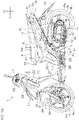
- Fig. 1A and Fig. 1B are left side views of the straddled vehicle 1 according to a preferred embodiment.
- Fig. 2 is a plan view of the straddled vehicle 1.
- An arrow U and an arrow F in Fig. 1A and Fig. 1B represent an upper direction and a front direction of the straddled vehicle 1, respectively.
- An arrow L in Fig 2 represents a left direction of the straddled vehicle 1. The same applies to other figures.
- the straddled vehicle 1 is a scooter, for example.
- the straddled vehicle 1 includes a frame 2 covered with an exterior cover and a front wheel Fw and a rear wheel Rw attached to the frame 2.
- the front wheel Fw is attached to the frame 2 via a front fork 8 described below.
- the rear wheel Rw is attached to the frame 2 via a swing unit 10 described below.
- the front wheel Fw includes a rubber tire Ft that rolls on the road surface and a metal wheel Fh surrounded by the tire Ft.
- the rear wheel Rw includes a rubber tire Rt that rolls on the road surface and a metal wheel Rh surrounded by the tire Rt.
- the frame 2 includes the head pipe 3 extending obliquely rearward and upward. As shown in Fig. 1B , the frame 2 further includes a down frame 4 extending obliquely rearward and downward from the head pipe 3, and a pair of lower frames 5 extending obliquely rearward and upward from the down frame 4. The pair of lower frames 5 overlap each other in a side view. Front ends of the pair of lower frames 5 are disposed below the head pipe 3.
- the straddled vehicle 1 includes a saddle type seat 6 on which a rider sits.
- a front end 6f of the seat 6 is disposed farther to the rear than the head pipe 3.
- the seat 6 may be for one person or may be for two persons.
- Fig. 1A shows an example of the later.
- the seat 6 includes a driver seat 6d on which a driver sits and a tandem seat 6t on which a passenger sits.
- the tandem seat 6t may be integral with the driver seat 6d or may be a seat separate from the driver seat 6d.
- the tandem seat 6t extends rearward from the driver seat 6d.
- the tandem seat 6t is disposed behind the driver seat 6d in a plan view.
- the straddled vehicle 1 includes the steering handle 7 to be operated by a driver, and the front fork 8 supporting rotatably the front wheel Fw.
- the front fork 8 which is an example of a front wheel supporting member, includes a pair of fork pipes 8p disposed on the right side and the left side of the front wheel Fw, respectively, and a steering shaft inserted in the head pipe 3.
- the steering shaft protrudes upward from an upper end portion of the head pipe 3.
- the steering handle 7 is connected to an upper end portion of the steering shaft.
- the steering handle 7 is disposed over the head pipe 3. When the steering handle 7 is operated, the front wheel Fw turns rightward and leftward around the center line of the head pipe 3 together with the steering handle 7 and the front fork 8.
- the straddled vehicle 1 is steered.
- the straddled vehicle 1 includes the swing unit 10 that is swingable upward and downward with respect to the frame 2.
- the swing unit 10 is an example of a power unit to cause the straddled vehicle 1 to travel.
- the swing unit 10 includes an engine 11 that rotates the rear wheel Rw and a transmission mechanism 12 that transmits the power of the engine 11 to the rear wheel Rw.
- the engine 11 is attached to the frame 2 via an anti-vibration link 9.
- the transmission mechanism 12 extends rearward from the engine 11.
- the rear wheel Rw is disposed on the right side of the transmission mechanism 12.
- the rear wheel Rw is rotatably supported by the transmission mechanism 12.
- the rear wheel Rw and the swing unit 10 are upward and downward swingable with respect to the frame 2 about a horizontal pivot axis Ap passing through the anti-vibration link 9 in the vehicle width direction.
- the engine 11 includes a piston that reciprocates in accordance with the combustion of air-fuel mixture containing air and fuel and a crank shaft that rotates in accordance with the reciprocation of the piston about a horizontal rotation axis Ac extending in the vehicle width direction.
- the engine 11 further includes a cylinder that houses the piston therein, and a crank case that houses the crank shaft therein.
- the crank shaft is disposed at a position farther to the rear than a rear end of the front wheel Fw (It corresponds to a rear end of the tire Ft of the front wheel Fw. The same applies hereinafter.) and farther to the front than a front end of the rear wheel Rw (It corresponds to a front end of the tire Rt of the rear wheel Rw. The same applies hereinafter.).
- the rotation of the crank shaft is transmitted to the rear wheel Rw via the transmission mechanism 12.
- the transmission mechanism 12 includes a transmission (a CVT (Continuously Variable Transmission), for example) that transmits a rotation, which is transmitted from the engine 11, toward the rear wheel Rw while changing a speed of the rotation, and a transmission case that houses the transmission therein.
- CVT Continuous Variable Transmission
- the straddled vehicle 1 includes a fuel tank 15 storing fuel to be supplied to the engine 11 and an air cleaner box 14 housing an element that removes foreign matter from air to be supplied to the engine 11.
- the air cleaner box 14 is disposed over the transmission case 13.
- the fuel tank 15 is disposed over the air cleaner box 14 in a side view.
- the fuel tank 15 is disposed under the seat 6.
- the fuel tank 15 is disposed behind a storage box 16 described below.
- the fuel tank 15 may be disposed under a foot board 27 described below.
- the straddled vehicle 1 includes the storage box 16 in which an article such as a helmet is put.
- the article is put in the storage box 16 through an opening provided in an upper end portion of the storage box 16.
- the seat 6 is disposed over the storage box 16.
- the opening of the storage box 16 is opened and closed by the seat 6.
- the seat 6 is connected to the storage box 16 via a seat hinge.
- the seat 6 is turnable upward and downward with respect to the storage box 16.
- Fig. 1A shows a state in which the seat 6 is disposed at a closed position in which the opening of the storage box 16 is closed by the seat 6.
- the straddled vehicle 1 includes a head lamp 17 that emits light forward and two front flashers 18 that flash in response to an operation by a driver.
- the straddled vehicle 1 further includes a tail lamp 20 that emits light rearward and two rear flashers 21 that flash in response to an operation by a driver.
- Fig. 1A shows an example in which the tail lamp 20 and the two rear flashers 21 are included in a rear lamp 19.
- the head lamp 17 and the front flashers 18 are disposed farther to the front than the front end 6f of the seat 6.
- the tail lamp 20 and the rear flashers 21 are disposed farther to the rear than the front end of the rear wheel Rw.
- the straddled vehicle 1 includes the exterior cover forming an outer surface of the straddled vehicle 1.
- the exterior cover includes a handle cover 22 disposed in front of and behind the steering handle 7, a front cover 23 disposed in front of the head pipe 3, and a front fender 24 disposed over the front wheel Fw.
- the handle cover 22 turns rightward and leftward together with the steering handle 7.
- the front fender 24 turns rightward and leftward together with the front fork 8.
- the handle cover 22, the front fender 24, the front fork 8 and the front wheel Fw move rightward and leftward together with the steering handle 7.
- the exterior cover further includes a leg shield 25 disposed in front of both legs of a driver sitting on the seat 6, and the foot board 27 on which both feet of the driver sitting on the seat 6 are placed.
- the foot board 27 is disposed below the front end 6f of the seat 6.
- the leg shield 25 extends upward from a front end portion of the foot board 27.
- the leg shield 25 is disposed farther to the front than the front end 6f of the seat 6.
- the leg shield 25 faces both legs of the driver sitting on the seat 6 in the front-rear direction.
- the leg shield 25 is disposed behind the front cover 23.
- the head pipe 3 is disposed between the front cover 23 and the leg shield 25 in the front-rear direction.
- An upper surface of the foot board 27 includes a flat portion 27f that is flat from its right end to its left end.
- any portion of the flat portion 27f is disposed on a horizontal straight line extending in the vehicle width direction.
- a cross-section of the flat portion 27f taken along a flat surface perpendicular to the front-rear direction extends linearly in the vehicle width direction from a right end of the cross-section to a left end of the cross-section.
- the flat portion 27f may be a smooth and flat surface without unevenness or may be a substantially flat surface including recessed portions or convex portions that cannot affect placing feet thereon (e.g., recessed portions or convex portions within a range from 2 mm to 1 cm).
- the exterior cover includes the pocket cover 26 forming together with the leg shield 25 a storage space in which an article is put.
- the pocket cover 26 is disposed farther to the front than the front end 6f of the seat 6.
- the pocket cover 26 is disposed behind the leg shield 25.
- the pocket cover 26 is attached to the leg shield 25.
- the storage space is formed between the leg shield 25 and the pocket cover 26 in the front-rear direction.
- the storage space extends downward from a take-in/take-out port formed between the leg shield 25 and the pocket cover 26 in the front-rear direction. An article is taken in or out from the storage space through the take-in/take-out port.
- the exterior cover includes an under cover disposed under the foot board 27.
- the under cover includes a lower under cover 28 disposed under the foot board 27, and a pair of rear under covers 29 disposed under the foot board 27 and disposed behind the foot board 27.
- the pair of lower frames 5 are disposed between the foot board 27 and the lower under cover 28 in the up-down direction.
- the pair of rear under covers 29 are disposed on the right side and the left side of the pair of lower frames 5, respectively.
- the rear under cover 29 is disposed farther outward than the engine 11 in the vehicle width direction and overlaps the engine 11 in a side view.
- the exterior cover includes a middle cover 30 disposed in front of the storage box 16, and a pair of side covers disposed on the right side and the left side of the storage box 16.
- the side cover includes an upper side cover 31 disposed under the seat 6 in a side view and a lower side cover 32 disposed under the upper side cover 31 in a side view.
- the upper side cover 31 and the lower side cover 32 are disposed outward of the storage box 16 in the vehicle width direction and overlap the storage box 16 in a side view.
- the middle cover 30 extends upward from the foot board 27.
- the middle cover 30 is disposed under the seat 6.
- the middle cover 30 is disposed behind the leg shield 25 and faces the leg shield 25 in the front-rear direction.
- the upper side cover 31 is disposed behind the middle cover 30.
- the lower side cover 32 is disposed behind the upper side cover 31.
- the exterior cover includes a rear fender 33 disposed in front of and behind the rear wheel Rw.
- the rear fender 33 includes a front board disposed over the rear wheel Rw, and a rear board extends obliquely rearward and downward from the front board.
- the front board is attached to the frame 2.
- the rear board is supported by the frame 2 via the front board.
- the front board and the rear board are disposed above the rear wheel Rw and overlap the rear wheel Rw in a plan view.
- a rear end of the rear board which corresponds to a rear end of the rear fender 33, is disposed farther to the rear than a rear end of the rear wheel Rw (It corresponds to a rear end of the tire Rt of the rear wheel Rw.
- the rear end of the rear board is disposed farther to the rear than a rear end 6r of the seat 6.
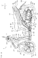
- Fig. 3 and Fig. 4 are respectively a left side view and a plan view of a portion of the straddled vehicle 1 including the foot board 27.
- Fig. 5 is an enlarged view of a portion of Fig. 3 .
- Fig. 6 is an enlarged view of a portion of Fig. 4 .
- Fig. 7 is a cross-sectional view showing a vertical cross section of an intermediate footrest 44 along line VII-VII shown in Fig. 5 .
- Fig. 8 is a cross-sectional view showing a vertical cross section of an upper footrest 45 along line VIII-VIII shown in Fig. 5 .
- an upper surface of the foot board 27 includes a flat portion 27f that is flat from its right end to its left end.
- the flat portion 27f includes a pair of front footrests 43 on which the feet of the driver are placed and a central footrest 42 positioned between the pair of front footrests 43 in the vehicle width direction.
- the pair of front footrests 43 are disposed at a mutually equal height.
- the central footrest 42 is disposed at a height equal to that of the pair of front footrests 43.
- a side surface 27s of the foot board 27 extends downward from an outer edge 43e of the front footrest 43. The driver is able to place his/her foot not only on the front footrest 43 but also on the central footrest 42.
- the upper surface of the foot board 27 includes, in addition to the pair of front footrests 43, a pair of intermediate footrests 44 on which the feet of the driver are placed and a pair of upper footrests 45 on which the feet of the passenger are placed.
- the straddled vehicle 1 includes a pair of footrest bars 47 that are collapsible. Each of the footrest bars 47 includes a lower footrest 46 on which the foot of the passenger is placed.
- the front footrest 43, the intermediate footrest 44, the upper footrest 45, and the lower footrest 46 are hereinafter collectively referred to as the footrests 43 to 46 if necessary.
- the pair of front footrests 43 are disposed on the right side and the left side of the vehicle center WO, respectively.
- a right foot of the driver is put on the right-side front footrest 43 or is put on the right-side intermediate footrest 44.
- a left foot of the driver is put on the left-side front footrest 43 or is put on the left-side intermediate footrest 44.
- a right foot of the passenger is put on the right-side upper footrest 45 or is put on the right-side lower footrest 46.
- a left foot of the passenger is put on the left-side upper footrest 45 or is put on the left-side lower footrest 46.
- the front footrest 43 and the intermediate footrest 44 are a portion of the foot board 27.
- the upper footrest 45 may be a portion of the exterior cover, such as a portion of the foot board 27, or may be a portion of the collapsible footrest bar.
- Fig. 4 shows an example in which the upper footrest 45 is a portion of the foot board 27, and the lower footrest 46 is a portion of the footrest bar 47.
- the footrest bar 47 is movable between the use position (position shown in Figs. 3 and 4 ) and the non-use position (position shown in Fig. 11 ).
- the footrest bar 47 described hereinafter is in the use position unless specific notice is given.
- Each of the footrests 43 to 46 may be a smooth and flat surface without unevenness or may be a substantially flat surface including recessed portions or convex portions that cannot affect placing feet thereon (e.g., recessed portions or convex portions within a range from 2 mm to 1 cm).
- Fig. 4 shows an example in which a plurality of convex portions 41 to minimize or prevent foot slipping are disposed at the front footrest 43, at the intermediate footrest 44, at the upper footrest 45, and at the lower footrest 46.
- the convex portions 41 are regularly disposed with intervals between the convex portions 41.
- the convex portion 41 may be straight or curved, or may be circular or elliptic.
- Fig. 6 shows an example in which straight convex portions and curved convex portions are disposed.
- the cross section of the convex portion along a vertical plane is, for example, trapezoidal or semicircular.
- the amount of protrusion of the convex portion from the surface of the footrest is equal or substantially equal.
- the surface of the footrest and the tops of the convex portions 41 form a substantial flat surface. The foot of the driver or of the passenger comes into contact with the tops of the convex portions 41.
- the front footrest 43 is disposed between the front wheel Fw and the rear wheel Rw in the front-rear direction in a side view.
- the front footrest 43 extends obliquely rearward and upward in a side view.
- the front footrest 43 may be horizontal from a front end 43f of the front footrest 43 to a rear end 43r of the front footrest 43, or may include a horizontal portion and an obliquely inclined portion with respect to a horizontal plane.
- any portion of the front footrest 43 is disposed below the front end 6f of the seat 6 in a side view. Any portion of the front footrest 43 is disposed below an upper end Rwu of the rear wheel Rw (which corresponds to an upper end of the tire Rt of the rear wheel Rw. The same applies hereinafter.) in a side view.
- the front end 43f of the front footrest 43 is disposed below the rotation axis Ac of the engine 11 in a side view.
- the rear end 43r of the front footrest 43 is disposed at a height equal to or substantially equal to that of the rotation axis Ac of the engine 11 in a side view.
- the front end 43f of the front footrest 43 is disposed farther to the front than the front end 6f of the seat 6 in a side view.
- the rear end 43r of the front footrest 43 is disposed farther to the rear than the front end 6f of the seat 6 in a side view.
- the rear end 43r of the front footrest 43 is disposed farther to the front than the rotation axis Ac of the engine 11 in a side view.
- the rear end 43r of the front footrest 43 is disposed farther to the front than the pivot axis Ap of the swing unit 10 in a side view.
- the pair of front footrests 43 are disposed below the handle cover 22, and overlap the handle cover 22 in a plan view.
- the central footrest 42 is disposed between the handle cover 22 and the seat 6 in the front-rear direction in a plan view.
- the outer edge 43e of the front footrest 43 extends outward in the vehicle width direction as the intermediate footrest 44 is approached. Therefore, an interval between the outer edges 43e of the pair of front footrests 43 in the vehicle width direction becomes wider as the intermediate footrest 44 is approached.
- the seat 6 is disposed between the pair of intermediate footrests 44 in the vehicle width direction in a plan view.
- the right-side intermediate footrest 44 extends rearward from the right-side front footrest 43 in a plan view.
- the left-side intermediate footrest 44 extends rearward from the left-side front footrest 43 in a plan view.
- the side covers 31 and 32 are disposed between the intermediate footrest 44 and the seat 6 in the vehicle width direction in a plan view.
- An outer edge 44e of the intermediate footrest 44 extends rearward from the outer edge 43e of the front footrest 43 in a plan view. In a plan view, the outer edge 44e of the intermediate footrest 44 extends outward in the vehicle width direction as the upper footrest 45 is approached. Therefore, an interval between the outer edges 44e of the pair of intermediate footrests 44 in the vehicle width direction becomes wider as the upper footrest 45 is approached. A maximum value of the interval between the outer edges 44e of the pair of intermediate footrests 44 in the vehicle width direction is larger than a maximum value of the interval between the outer edges 43e of the pair of front footrests 43 in the vehicle width direction.
- the intermediate footrest 44 extends obliquely rearward and upward from the front footrest 43 in a side view.
- the intermediate footrest 44 and the front footrest 43 form a circular arc in a side view, which is downward convex, at a connection portion between footrests 44 and 43.
- An inclination angle of the intermediate footrest 44 with respect to the horizontal plane is larger than an inclination angle of the front footrest 43 with respect to the horizontal plane.
- the intermediate footrest 44 is shorter in the front-rear direction than the front footrest 43.
- a distance in the front-rear direction from the front end of the intermediate footrest 44 to the rear end of the intermediate footrest 44 is shorter than a distance in the front-rear direction from the front end 43f of the front footrest 43 to the rear end 43r of the front footrest 43.
- any portion of the intermediate footrest 44 is disposed below the front end 6f of the seat 6 in a side view. Any portion of the intermediate footrest 44 is disposed above a rotational center C1 of the rear wheel Rw in a side view. Any portion of the intermediate footrest 44 is disposed farther to the rear than the front end 6f of the seat 6 in a side view. Any portion of the intermediate footrest 44 is disposed farther to the front than a front end Rwf of the rear wheel Rw in a side view. Any portion of the intermediate footrest 44 is disposed farther to the front than the rotation axis Ac of the engine 11 in a side view. The rear end of the intermediate footrest 44 is disposed farther to the rear than the pivot axis Ap of the swing unit 10 in a side view.
- the front end of the intermediate footrest 44 corresponds to the rear end 43r of the front footrest 43.
- the rear end of the intermediate footrest 44 corresponds to a front end 45f of the upper footrest 45.
- the rear end of the intermediate footrest 44 is disposed above the front end of the intermediate footrest 44 in a side view.
- the rear end of the intermediate footrest 44 is disposed above the rotation axis Ac of the engine 11 in a side view.
- the rear end of the intermediate footrest 44 is disposed above an upper end Rhu of the wheel Rh of the rear wheel Rw in a side view.
- the rear end of the intermediate footrest 44 is disposed above an upper end 14u of the air cleaner box 14 in a side view.
- the rear end of the intermediate footrest 44 is disposed at a height equal to or substantially equal to that of the upper end Rwu of the rear wheel Rw in a side view.
- Fig. 7 shows a cross section along a vertical plane that perpendicularly intersects the front-rear direction.
- an inner end 44i of the intermediate footrest 44 is disposed above an outer end 44o of the intermediate footrest 44 and the intermediate footrest 44 extends obliquely upward toward the vehicle center WO (see Fig. 4 ).
- the inner end 44i of the intermediate footrest 44 may be disposed at a height equal to that of the outer end 44o of the intermediate footrest 44, or may be disposed below the outer end 44o of the intermediate footrest 44.
- the seat 6 is disposed between the pair of upper footrests 45 in the vehicle width direction in a plan view.
- the right-side upper footrest 45 extends rearward from the right-side intermediate footrest 44 in a plan view.
- the left-side upper footrest 45 extends rearward from the left-side intermediate footrest 44 in a plan view.
- An outer edge 45e of the upper footrest 45 extends rearward from the outer edge 44e of the intermediate footrest 44 in a plan view.
- the side covers 31 and 32 are disposed between the upper footrest 45 and the seat 6 in the vehicle width direction in a plan view.
- the upper footrest 45 includes a front rest portion 45F that extends obliquely rearward and downward from the intermediate footrest 44 in a side view and a rear rest portion 45R that extends obliquely rearward and upward from the front rest portion 45F in a side view.
- the intermediate footrest 44 and the front rest portion 45F form a convex portion, which protrudes upward in a side view, at a connection portion between the intermediate footrest 44 and the front rest portion 45F.
- the front rest portion 45F and the rear rest portion 45R form a concave portion, which is downward concaved in a side view, at a connection portion between the front rest portion 45F and the rear rest portion 45R.
- the inclination angle of the rear rest portion 45R with respect to a horizontal plane is smaller than the inclination angle of the intermediate footrest 44 with respect to the horizontal plane.
- the inclination angle of the upper footrest 45 with respect to the horizontal plane varies at an area between the front end 45f of the upper footrest 45 and the rear end 45r of the upper footrest 45.
- the inclination angle of the upper footrest 45 with respect to the horizontal plane may be constant from the front end 45f of the upper footrest 45 to the rear end 45r of the upper footrest 45.
- the inclination angle of the upper footrest 45 with respect to the horizontal plane may be smaller than the inclination angle of the intermediate footrest 44 with respect to the horizontal plane.
- the upper footrest 45 may be entirely or partially horizontal.
- the rear rest portion 45R may be horizontal.
- the front end of the front rest portion 45F corresponds to the front end 45f of the upper footrest 45.
- the rear end 45r of the upper footrest 45 is disposed above the front end 45f of the upper footrest 45.
- the upper footrest 45 is shorter in the front-rear direction than the intermediate footrest 44. In other words, the distance in the front-rear direction from the front end 45f of the upper footrest 45 to the rear end 45r of the upper footrest 45 is shorter than the distance in the front-rear direction from the front end (which corresponds to the rear end 43r) of the intermediate footrest 44 to the rear end (which corresponds to the front end 45f) of the intermediate footrest 44.
- any portion of the upper footrest 45 is disposed farther to the front than the rotation axis Ac of the engine 11 in a side view. As shown in Fig. 3 , any portion of the upper footrest 45 is disposed below the front end 6f of the seat 6 in a side view. Any portion of the upper footrest 45 is disposed above the upper end Rhu of the wheel Rh of the rear wheel Rw in a side view.
- Fig. 8 shows a cross section along the vertical plane that perpendicularly intersects the front-rear direction.
- an inner end 45i of the upper footrest 45 is disposed below an outer end 45o of the upper footrest 45.
- the upper footrest 45 extends obliquely downward toward the vehicle center WO (see Fig. 4 ).
- the inner end 45i of the upper footrest 45 may be disposed at a height equal to that of the outer end 45o of the upper footrest 45, or may be disposed above the outer end 45o of the upper footrest 45.
- the upper footrest 45 protrudes outward from the lower side cover 32 in the vehicle width direction.
- the lower side cover 32 extends upward from the upper footrest 45.
- a portion of the lower side cover 32 is disposed over the upper footrest 45 in a side view.
- An outer end 32o of the lower side cover 32 corresponds to an outer end of the side covers 31 and 32.
- any portion of the upper footrest 45 is disposed below the outer end 32o of the lower side cover 32.
- the inner end 45i of the upper footrest 45 is disposed farther inward than the outer end 32o of the lower side cover 32 in the vehicle width direction, and the outer end 45o of the upper footrest 45 is disposed farther outward than the outer end 32o of the lower side cover 32 in the vehicle width direction. Therefore, the side covers 31 and 32 overlap the upper footrest 45 in a plan view.
- the lower footrest 46 is a portion of the collapsible footrest bar 47.
- the footrest bar 47 is movable to and from the frame 2 between the use position and the non-use position.
- Fig. 8 shows a state in which the footrest bar 47 is disposed in the use position.
- the use position is a position in which a distal end portion 47d of the footrest bar 47 is disposed farther outward than a proximal end portion 47p of the footrest bar 47 in the vehicle width direction.
- the non-use position i.e., position shown in Fig.
- the distal end portion 47d of the footrest bar 47 is disposed inward in the vehicle width direction as compared with a case in which the footrest bar 47 is disposed in the use position.
- the foot of the passenger is placed on the lower footrest 46 when the footrest bar 47 is disposed in the use position.
- the footrest bar 47 is attached to the frame 2 by a hinge 48.
- the hinge 48 includes a bracket 48b fixed to the frame 2 and a pin 48p interposed between the bracket 48b and the footrest bar 47.
- the footrest bar 47 is rotatable around the pin 48p with respect to the frame 2.
- the pin 48p penetrates through the footrest bar 47. Both end portions of the pin 48p are supported by the bracket 48b.
- the use position and the non-use position are positions of both ends of a range within which the footrest bar 47 is moved.
- the footrest bar 47 includes a bar end 47e into which the pin 48p is inserted and a swing bar 47b extending outward from the bar end 47e in the vehicle width direction.
- the proximal end portion 47p is a portion of the bar end 47e.
- the distal end portion 47d is a portion of the swing bar 47b.
- the bar end 47e is disposed inside the bracket 48b.
- the swing bar 47b is disposed outside the bracket 48b.
- the lower footrest 46 is a portion of the swing bar 47b. Therefore, the foot of the passenger is placed on the swing bar 47b. At least a portion of the lower footrest 46 is visible in a plan view.
- An outer end 46o of the lower footrest 46 corresponds to an upper end of the lower footrest 46.
- An inner end 46i of the lower footrest 46 corresponds to a lower end of the lower footrest 46.
- the outer end 46o of the lower footrest 46 and the upper end of the lower footrest 46 are not necessarily required to coincide with each other.
- the inner end 46i of the lower footrest 46 and the lower end of the lower footrest 46 are not necessarily required to coincide with each other.
- the distance in the vehicle width direction i.e., distance D4 shown in Fig.
- the seat 6 is disposed between the pair of lower footrests 46 in the vehicle width direction in a plan view.
- the upper footrest 45 is disposed above the lower footrest 46, and overlaps the lower footrest 46 in a plan view (see Fig. 6 ).
- the right-side lower footrest 46 protrudes outward from the right-side upper footrest 45 in the vehicle width direction in a plan view.
- the left-side lower footrest 46 protrudes outward from the left-side upper footrest 45 in the vehicle width direction in a plan view.
- the upper footrest 45 is disposed between the lower footrest 46 and the side covers 31, 32 in the vehicle width direction in a plan view.
- any portion of the lower footrest 46 is disposed above the front footrest 43 in a side view. Any portion of the lower footrest 46 is disposed above the rotation axis Ac of the engine 11 in a side view. Any portion of the lower footrest 46 is disposed below the upper footrest 45 in a side view. Any portion of the lower footrest 46 is disposed below the upper end Rhu of the wheel Rh of the rear wheel Rw in a side view. Any portion of the lower footrest 46 is disposed at a position higher than the front end (which corresponds to the rear end 43r) of the intermediate footrest 44 in a side view and lower than the rear end (which corresponds to the front end 45f) of the intermediate footrest 44 in a side view.
- any portion of the lower footrest 46 is disposed farther to the rear than the front footrest 43 in a side view. Any portion of the lower footrest 46 is disposed farther to the rear than the pivot axis Ap of the swing unit 10 in a side view. Any portion of the lower footrest 46 is disposed farther to the front than the rotation axis Ac of the engine 11 in a side view. Any portion of the lower footrest 46 is disposed farther to the front than the rear end 45r of the upper footrest 45 in a side view (see Fig. 5 ). At least a portion of the lower footrest 46 is disposed at a position farther to the rear than the front end 45f of the upper footrest 45 in a side view and farther to the front than the rear end 45r of the upper footrest 45 in a side view.
- the upper footrest 45 is disposed farther outward than the storage box 16 in the vehicle width direction, and overlaps the storage box 16 in a side view.
- the rear end (which corresponds to the front end 45f) of the intermediate footrest 44 is disposed farther outward than the storage box 16 in the vehicle width direction, and overlaps the storage box 16 in a side view.
- Any portion of the upper footrest 45 is disposed above a lower end 16L of the storage box 16 in a side view.
- any portion of the lower footrest 46 is disposed below the lower end 16L of the storage box 16 in a side view, and does not overlap the storage box 16 in a side view.
- the rear under cover 29 of the exterior cover is disposed behind the intermediate footrest 44 in a side view.
- the rear under cover 29 is disposed below the upper footrest 45 in a side view.
- a portion of the rear under cover 29 is disposed between the intermediate footrest 44 and the lower footrest 46 in the front-rear direction in a side view.
- the lower footrest 46 overlaps the rear under cover 29 in a side view.
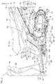
- Fig. 9 is an enlarged view of a portion of Fig. 8 .
- Fig. 10 and Fig. 11 are each a rear view of a portion of the straddled vehicle 1.
- Fig. 10 shows a state in which the lower footrest 46 is disposed in the use position.
- Fig. 11 shows a state in which the lower footrest 46 is disposed in the non-use position.
- a side surface 29s of the rear under cover 29 extends downward from the side surface 27s of the foot board 27.
- the side surface 29s of the rear under cover 29 extends obliquely downward toward the vehicle center WO (see Fig. 4 ).
- the side surface 29s of the rear under cover 29 includes the ceiling portion 49 inward concaved in the vehicle width direction. A portion of the ceiling portion 49 is disposed over the lower footrest 46. The ceiling portion 49 and the lower footrest 46 face each other in the up-down direction.
- the ceiling portion 49 extends obliquely downward toward the vehicle center WO (see Fig. 4 ).
- the ceiling portion 49 may extend obliquely downward from an upper end 49u of the ceiling portion 49 to a lower end 49L of the ceiling portion 49, and may include at least one of a horizontal portion and a vertical portion and an inclined portion extending obliquely downward toward the vehicle center WO.
- the upper end 49u of the ceiling portion 49 corresponds to an outer end of the ceiling portion 49 disposed at an outermost position in the vehicle width direction in the ceiling portion 49.
- the lower end 49L of the ceiling portion 49 is disposed farther inward than the upper end 49u of the ceiling portion 49 in the vehicle width direction.
- the lower footrest 46 When the lower footrest 46 is disposed in the use position, the lower footrest 46 is disposed farther outward than the ceiling portion 49 in the vehicle width direction, and does not overlap the ceiling portion 49 in a rear view as shown in Fig. 10 . On the other hand, when the lower footrest 46 is disposed in the non-use position, the lower footrest 46 is disposed behind the ceiling portion 49, and overlaps the ceiling portion 49 in a rear view as shown in Fig. 11 . When the lower footrest 46 is disposed in the use position, at least a portion of the lower footrest 46 may overlap the ceiling portion 49 in a rear view.
- the upper end 49u of the ceiling portion 49 and the lower end 49L of the ceiling portion 49 are disposed below any portion of the upper footrest 45.
- the upper end 49u of the ceiling portion 49 and the lower end 49L of the ceiling portion 49 are disposed above any portion of the lower footrest 46. Therefore, the upper end 49u of the ceiling portion 49 and the lower end 49L of the ceiling portion 49 are disposed above the outer end 46o of the lower footrest 46 that corresponds to the upper end of the lower footrest 46.
- the outer end 45o of the upper footrest 45 and the inner end 46i of the lower footrest 46 are disposed at positions farther inward than the upper end 49u of the ceiling portion 49 in the vehicle width direction and farther outward than the lower end 49L of the ceiling portion 49 in the vehicle width direction. At least a portion of the upper footrest 45 is disposed above the ceiling portion 49, and overlaps the ceiling portion 49 in a plan view. At least a portion of the ceiling portion 49 is disposed above the lower footrest 46, and overlaps the lower footrest 46 in a plan view. Therefore, the ceiling portion 49 overlaps both the upper footrest 45 and the lower footrest 46 in a plan view.
- the upper end 49u of the ceiling portion 49 and the lower end 49L of the ceiling portion 49 are disposed farther inward than the outer end 46o of the lower footrest 46 in the vehicle width direction.
- the upper end 49u of the ceiling portion 49 is disposed farther outward than the inner end 46i of the lower footrest 46 in the vehicle width direction.
- the lower end 49L of the ceiling portion 49 is disposed farther inward than the inner end 46i of the lower footrest 46 in the vehicle width direction.
- the lower end 49L of the ceiling portion 49 may be disposed farther outward than the inner end 46i of the lower footrest 46 in the vehicle width direction.
- the lower end 49L of the ceiling portion 49 is disposed farther outward than the outer end 32o of the lower side cover 32 that corresponds to the outer end of the side covers 31 and 32 in the vehicle width direction.
- a distance D1 in the up-down direction from the upper end 49u of the ceiling portion 49 to the lower end 49L of the ceiling portion 49 is longer than a distance D2 in the up-down direction from the lower end 49L of the ceiling portion 49 to the upper end of the lower footrest 46 (which corresponds to the outer end 46o).
- the distance D1 is longer than a distance D3 in the vehicle width direction from the upper end 49u of the ceiling portion 49 to the lower end 49L of the ceiling portion 49.
- the distance D1 is longer than a distance D4 in the vehicle width direction from the outer end 46o of the lower footrest 46 to the inner end 46i of the lower footrest 46.
- the distance D2 is shorter than the distance D3.
- the distance D2 is shorter than the distance D4.
- the distance D3 is shorter than the distance D4.
- a relationship among the distance D1 to the distance D4 is not limited to this.
- the foot of the driver sitting on the driver seat 6d (in detail, the footwear of the driver) is placed on the front footrest 43.
- the foot of the passenger sitting on the tandem seat 6t (in detail, the footwear of the passenger) is placed on the upper footrest 45 or on the lower footrest 46.
- the passenger is able to select a position at which the foot is placed from the upper footrest 45 and the lower footrest 46.
- the upper footrest 45 and the lower footrest 46 are disposed at mutually different heights.
- the foot of the passenger would be placed on the upper footrest 45 when a small person sits on the tandem seat 6t or when the sitting position of the driver is more rearward than usual. Therefore, it is possible for the passenger to place the foot on the upper footrest 45 or on the lower footrest 46 in a comfortable posture regardless of the physical size of the passenger or regardless of the sitting position of the driver.
- the foot of the passenger would be placed on the lower footrest 46 when a person of average stature or of large stature sits on the tandem seat 6t.
- the foot of the passenger is disposed between the ceiling portion 49 of the exterior cover and the lower footrest 46.
- a cross section of the ceiling portion 49 (hereinafter referred to as a "predetermined cross section" if necessary) that is perpendicular to the front-rear direction and that is along a vertical plane passing through the lower footrest 46, the upper end 49u of the ceiling portion 49 is disposed at a more outward position in the vehicle width direction than the inner end 46i of the lower footrest 46. Therefore, the ankle of the passenger whose foot is placed on the lower footrest 46 is disposed near the upper end 49u of the ceiling portion 49 in the vehicle width direction.
- the lower end 49L of the ceiling portion 49 is disposed at a more inward position in the vehicle width direction than the upper end 49u of the ceiling portion 49. Therefore, in the predetermined cross section of the ceiling portion 49, the ceiling portion 49 extends inward toward the lower end 49L of the ceiling portion 49 in the vehicle width direction. Human medial malleolus protrudes inward from the ankle. Therefore, the ceiling portion 49 recedes inward from the medial malleolus of the passenger in the vehicle width direction in proportion to an approach to the lower end 49L of the ceiling portion 49.
- Fig. 12 shows a cross section along a vertical plane that perpendicularly intersects the front-rear direction.
- An alternate long and two short dashed line represents the foot of the passenger placed on the lower footrest 46.
- the ceiling portion 49 extends inward in the vehicle width direction as the lower footrest 46 is approached, and therefore the ceiling portion 49 is away from the heel of the passenger inward in the vehicle width direction. Similarly, the ceiling portion 49 is away from the medial malleolus of the passenger inward in the vehicle width direction.
- the upper end 49u of the ceiling portion 49 is disposed near the ankle of the passenger whose foot is placed on the lower footrest 46, whereas the ceiling portion 49 recedes inward from the medial malleolus of the passenger in the vehicle width direction as the lower end 49L of the ceiling portion 49 is approached.
- the medial malleolus of the passenger enters a space under the ceiling portion 49 depending on how to place the foot on the lower footrest 46. Therefore, how to place the foot of the passenger on the lower footrest 46 is not easily restricted by the ceiling portion 49.
- the ceiling portion 49 is concaved inward in the vehicle width direction, and therefore the heel of the passenger does not easily come into contact with the ceiling portion 49 even if the position of the foot with respect to the lower footrest 46 is more inward than usual. Therefore, a range within which the foot is able to be placed on the lower footrest 46 is widened in the vehicle width direction. In other words, the passenger is able not only to select a position at which the foot is placed from the upper footrest 45 and the lower footrest 46 but also to move this position in the vehicle width direction within the range of the lower footrest 46. From these reasons, it is possible to make the comfort of the passenger even higher.
- the intermediate footrest 44 is provided in addition to the front footrest 43, the upper footrest 45, and the lower footrest 46.
- the intermediate footrest 44 extends rearward from the front footrest 43. Therefore, the driver sitting on the driver seat 6d is able to select a position at which the foot is placed from the front footrest 43 and the intermediate footrest 44, and a range within which the foot of the driver is able to be placed is widened in the front-rear direction. Additionally, the intermediate footrest 44 extends forward from the upper footrest 45.
- the passenger sitting on the tandem seat 6t is able to select a position at which the foot is placed from among the upper footrest 45, the lower footrest 46, and the intermediate footrest 44, and a range within which the foot of the passenger is able to be placed is widened in the front-rear direction.
- the intermediate footrest 44 is disposed at a more rearward position than the front end 6f of the seat 6 that corresponds to the front end of the driver seat 6d. Therefore, the underside of the foot is easily directed rearward when the driver places the foot on the intermediate footrest 44.
- the rear end of the intermediate footrest 44 that corresponds to the front end 45f of the upper footrest 45 is disposed at a position higher than the upper end Rhu of the wheel Rh of the rear wheel Rw and farther to the front than the rotation axis Ac of the engine 11 in a side view.
- the rear end of the intermediate footrest 44 is disposed not only at a comparatively forward position but also at a comparatively high position.
- the intermediate footrest 44 is obliquely inclined at a comparatively great angle with respect to a horizontal plane.
- the driver is able to easily place the foot on the intermediate footrest 44 if the inclination angle of the intermediate footrest 44 is great. Therefore, it is possible to improve the comfort of the driver.
- the outer end 45o of the upper footrest 45 and the inner end 45i of the upper footrest 45 are disposed below the outer end of the side covers 31 and 32 that correspond to the outer end 32o of the lower side cover 32.
- the outer end 45o of the upper footrest 45 is disposed at a more outward position in the vehicle width direction than the outer end of the side covers 31 and 32, whereas the inner end 45i of the upper footrest 45 is disposed at a more inward position in the vehicle width direction than the outer end of the side covers 31 and 32. Therefore, it is possible to increase the width of the upper footrest 45 in the vehicle width direction while minimizing or preventing an increase in width of the straddled vehicle 1.
- the rear end 45r of the upper footrest 45 and the rear end 46r of the lower footrest 46 are disposed at a more forward position than the rotation axis Ac of the engine 11. Therefore, the passenger sitting on the tandem seat 6t is able to place the foot on either one of the upper footrest 45 and the lower footrest 46 in a comfortable posture in which the knee of the passenger is straightened.
- the lower footrest 46 is disposed not only at a lower position than the upper footrest 45 but also at a more forward position than the rotation axis Ac of the engine 11, and therefore the distance from the tandem seat 6t to the lower footrest 46 increases. Therefore, the passenger is able to place the foot on the lower footrest 46 in a comfortable posture in which the knee is straightened even when a large person sits on the tandem seat 6t.
- the lower end of the lower footrest 46 which corresponds to the inner end 46i of the lower footrest 46, is disposed above the rotation axis Ac of the engine 11. Therefore, the lower end of the upper footrest 45 is also disposed above the rotation axis Ac of the engine 11. As thus described, the upper footrest 45 and the lower footrest 46 are disposed at a comparatively high position, hence enabling the passenger sitting on the tandem seat 6t to place the foot on either one of the upper and lower footrests 45 and 46 without extremely straighten the knee.
- the width of the upper footrest 45 is smaller than the width of the lower footrest 46.
- the length of the upper footrest 45 in the vehicle width direction is shorter than the length of the lower footrest 46 in the vehicle width direction. It is conceivable that the foot of a small person would be placed on the upper footrest 45. A person of small stature is smaller in foot width than a person of average stature or a large person in many cases. Therefore, the passenger is able to place the foot on the upper footrest 45 even if the upper footrest 45 is shorter than the lower footrest 46 in the vehicle width direction. Therefore, it is possible to minimize or prevent an increase in width of the straddled vehicle 1 while maintaining the comfort of the passenger.
- the upper footrest 45 and the lower footrest 46 are disposed not only at mutually different heights but also with a sufficient distance therebetween in the up-down direction.
- the upper footrest 45 overlaps the storage box 16 in a side view
- the lower footrest 46 is disposed below the storage box 16, and does not overlap the storage box 16 in a side view.
- the upper footrest 45 and the lower footrest 46 are sufficiently away from each other in the up-down direction, and therefore the passenger is able to comfortably place the foot on the upper footrest 45 or on the lower footrest 46 regardless of the physical size of the passenger or regardless of a sitting position of the driver.
- the ceiling portion 49 overlaps both the upper footrest 45 and the lower footrest 46 in a plan view.
- at least a portion of the ceiling portion 49 is disposed above the lower footrest 46, and overlaps the lower footrest 46 in a plan view.
- At least a portion of the upper footrest 45 is disposed above the ceiling portion 49, and overlaps the ceiling portion 49 in a plan view.
- the distance D1 in the up-down direction from the upper end 49u of the ceiling portion 49 to the lower end 49L of the ceiling portion 49 is relatively long. Therefore, the upper end 49u of the ceiling portion 49 is sufficiently away upward from the lower footrest 46.
- the distance D2 in the up-down direction from the lower end 49L of the ceiling portion 49 to the upper end of the lower footrest 46 (which corresponds to the outer end 46o) is relatively short. Therefore, the lower end 49L of the ceiling portion 49 is disposed near the lower footrest 46 with respect to the up-down direction. In this layout, the medial malleolus of the passenger whose foot is placed on the lower footrest 46 is easily disposed at a height between the upper end 49u of the ceiling portion 49 and the lower end 49L of the ceiling portion 49.
- the distance D3 in the vehicle width direction from the upper end 49u of the ceiling portion 49 to the lower end 49L of the ceiling portion 49 is relatively long.
- the ceiling portion 49 is largely concaved inward in the vehicle width direction, and a comparatively large space is secured below the ceiling portion 49. Therefore, the heel of the passenger whose foot is placed on the lower footrest 46 does not easily come into contact with the ceiling portion 49, and the position of the foot of the passenger with respect to the lower footrest 46 is not easily restricted by the ceiling portion 49. Therefore, it is possible to make the comfort of the passenger even higher.
- the rear end of the intermediate footrest 44 (which corresponds to the front end 45f) may be disposed below the upper end Rhu of the wheel Rh of the rear wheel Rw.
- the rear end of the intermediate footrest 44 may be disposed at a more rearward position than the rotation axis Ac of the engine 11.
- the intermediate footrest 44 may be omitted from the straddled vehicle 1.
- the side covers 31 and 32 are not necessarily required to overlap the upper footrest 45 in a plan view.
- the inner end 45i of the upper footrest 45 may be disposed at a more outward position in the vehicle width direction than the outer end of the side covers 31 and 32 that correspond to the outer end 32o of the lower side cover 32.
- At least one of the rear end 45r of the upper footrest 45 and the rear end 46r of the lower footrest 46 may be disposed at a more rearward position than the rotation axis Ac of the engine 11.
- the lower end of the lower footrest 46 (which corresponds to the inner end 46i) may be disposed below the rotation axis Ac of the engine 11.
- the width of the upper footrest 45 may be equal to the width of the lower footrest 46, or may be wider than the width of the lower footrest 46.
- All portions of the upper footrest 45 may be disposed below the lower end 16L of the storage box 16.
- both the upper footrest 45 and the lower footrest 46 may overlap the storage box 16 in a side view.
- the storage box 16 may be omitted from the straddled vehicle 1.
- the upper footrest 45 is not necessarily required to overlap the ceiling portion 49 of the lower under cover 28 in a plan view.
- the lower footrest 46 may overlap both the intermediate footrest 44 and the upper footrest 45 in a plan view. Alternatively, the lower footrest 46 may overlap the intermediate footrest 44 in a plan view without overlapping the upper footrest 45 in a plan view.
- the central footrest 42 of the foot board 27 may be disposed above the pair of front footrests 43 not at a height equal to that of the pair of front footrests 43.
- the straddled vehicle 1 may include, instead of the engine 11 which is an example of a power source, an electric motor which is another example of the power source or may include both of the engine 11 and the electric motor.
- the straddled vehicle 1 is not limited to a scooter type motorcycle in which the engine 11 is swingable with respect to the frame 2, but may be an underbone type motorcycle in which the power source is fixed to the frame 2.
- the straddled vehicle 1 is not limited to a two-wheeled vehicle, but may be a three-wheeled vehicle or a four-wheeled vehicle. In a case of a three-wheeled vehicle, two front wheels Fw may be provided or two rear wheels Rw may be provided.
- the straddled vehicle 1 may be a snowmobile.
Landscapes
- Engineering & Computer Science (AREA)
- Mechanical Engineering (AREA)
- Automatic Cycles, And Cycles In General (AREA)
Abstract
Description
- The present invention relates to a straddled vehicle.
-
JP 2013067304 A -
JP H0492791 A - The scooters disclosed in
JP 2013067304 A JP H0492791 A - Without being limited to this, it may be difficult for the passenger to place his/her foot on the tandem footrest depending on a sitting position of the driver. For example, if the sitting position of the driver is more rearward than usual, the passenger will be required to widen his/her legs more or will be required to move rearward the position at which the passenger sits. In the latter case, sometimes the passenger must place the foot on the tandem footrest in a cramped posture in which his/her knees are excessively straightened.
- In the pillion step disclosed in
JP 2013067304 A JP H0492791 A JP H0492791 A - Therefore, in the scooters disclosed in
JP 2013067304 A JP H0492791 A - It is therefore an object of the present invention to provide a straddled vehicle enabling a passenger to have high comfort. According to the present invention said object is achieved by a straddled vehicle according to
claim 1. Preferred embodiments are laid down in the dependent claims. - A preferred embodiment provides a straddled vehicle including a driver seat on which a driver sits, a tandem seat that is disposed behind the driver seat in a plan view and on which a passenger sits, a front footrest on which a foot of the driver sitting on the driver seat is placed, an upper footrest that is disposed farther to the rear than the front footrest and on which a foot of the passenger sitting on the tandem seat is placed, a lower footrest that is disposed at a position farther to the rear than the front footrest and lower than the upper footrest and on which the foot of the passenger sitting on the tandem seat is placed, and an exterior cover including a side surface that includes a ceiling portion at least a portion of which is disposed above the lower footrest, the ceiling portion facing the lower footrest in an up-down direction, wherein, in a predetermined cross section of the ceiling portion along a vertical plane that perpendicularly intersects a front-rear direction, an upper end of the ceiling portion is disposed above an upper end of the lower footrest, and a lower end of the ceiling portion is disposed farther inward than the upper end of the ceiling portion in a vehicle width direction, and at least a portion of the lower footrest is disposed at a position farther inward than the upper end of the ceiling portion in the vehicle width direction and farther outward than the lower end of the ceiling portion in the vehicle width direction.
- According to this configuration, the foot of the driver sitting on the driver seat (in detail, the footwear of the driver) is placed on the front footrest. The foot of the passenger sitting on the tandem seat (in detail, the footwear of the passenger) is placed on the upper footrest or on the lower footrest. In other words, the passenger is able to select a position at which the foot is placed from the upper footrest and the lower footrest. The upper footrest and the lower footrest are disposed at mutually different heights. For example, the foot of the passenger would be placed on the upper footrest when a small person sits on the tandem seat or when the sitting position of the driver is more rearward than usual. Therefore, it is possible for the passenger to place the foot on the upper footrest or on the lower footrest in a comfortable posture regardless of the physical size of the passenger or regardless of the sitting position of the driver.
- For example, the foot of the passenger would be placed on the lower footrest when a person of average stature or of large stature sits on the tandem seat. In this case, the foot of the passenger is disposed between the ceiling portion of the exterior cover and the lower footrest. In a cross section of the ceiling portion (hereinafter referred to as a "predetermined cross section" if necessary) that is perpendicular to the front-rear direction and that is along a vertical plane passing through the lower footrest, the upper end of the ceiling portion is disposed farther outward than the inner end of the lower footrest in the vehicle width direction. Therefore, the ankle of the passenger whose foot is placed on the lower footrest is disposed near the upper end of the ceiling portion in the vehicle width direction.
- On the other hand, in the predetermined cross section of the ceiling portion, the lower end of the ceiling portion is disposed farther inward than the upper end of the ceiling portion in the vehicle width direction. Therefore, in the predetermined cross section of the ceiling portion, the ceiling portion extends inward in the vehicle width direction toward the lower end of the ceiling portion. Human medial malleolus protrudes inward from the ankle. Therefore, the ceiling portion recedes inward from the medial malleolus of the passenger in the vehicle width direction as the lower end of the ceiling portion is approached.
- As thus described, in the predetermined cross section of the ceiling portion, the upper end of the ceiling portion is disposed near the ankle of the passenger whose foot is placed on the lower footrest, whereas the ceiling portion recedes inward from the medial malleolus of the passenger in the vehicle width direction as the lower end of the ceiling portion is approached. The medial malleolus of the passenger enters a space under the ceiling portion depending on how to place the foot on the lower footrest. Therefore, how to place the foot of the passenger on the lower footrest is not easily restricted by the ceiling portion.
- Additionally, the ceiling portion is concaved inward in the vehicle width direction, and therefore the heel of the passenger does not easily come into contact with the ceiling portion even if the position of the foot with respect to the lower footrest is more inward than usual. Therefore, a range within which the foot is able to be placed on the lower footrest is widened in the vehicle width direction. In other words, the passenger is able not only to select a position at which the foot is placed from the upper footrest and the lower footrest but also to move this position in the vehicle width direction within the range of the lower footrest. From these reasons, it is possible to make the comfort of the passenger even higher.
- In the present preferred embodiment, at least one of the following features may be added to the straddled vehicle.
- The straddled vehicle further includes an intermediate footrest that extends rearward from the front footrest to the upper footrest and on which the foot of the driver or of the passenger is placed.
- According to this configuration, the intermediate footrest is provided in addition to the front footrest, the upper footrest, and the lower footrest. The intermediate footrest extends rearward from the front footrest. Therefore, the driver sitting on the driver seat is able to select a position at which the foot is placed from the front footrest and the intermediate footrest, and a range within which the foot of the driver is able to be placed is widened in the front-rear direction. Additionally, the intermediate footrest extends forward from the upper footrest. Therefore, the passenger sitting on the tandem seat is able to select a position at which the foot is placed from among the upper footrest, the lower footrest, and the intermediate footrest, and a range within which the foot of the passenger is able to be placed is widened in the front-rear direction.
- The straddled vehicle further includes a rear wheel including a tire that rolls on a road surface and a wheel surrounded by the tire and an engine that rotates the rear wheel, wherein any portion of the intermediate footrest is disposed farther to the rear than a front end of the driver seat, and a rear end of the intermediate footrest is disposed at a position higher than an upper end of the wheel of the rear wheel and farther to the front than a rotation axis of the engine in a side view.
- According to this configuration, the intermediate footrest is disposed farther to the rear than the front end of the driver seat that corresponds to the front end of the seat. Therefore, the underside of the foot is easily directed rearward when the driver places the foot on the intermediate footrest. On the other hand, the rear end of the intermediate footrest is disposed above the upper end of the wheel of the rear wheel in a side view, and is disposed farther to the front than the rotation axis of the engine. In other words, the rear end of the intermediate footrest is disposed not only at a comparatively forward position but also at a comparatively high position. Therefore, the intermediate footrest is obliquely inclined at a comparatively great angle with respect to a horizontal plane. When the underside of the foot of the driver is directed rearward, the driver is able to easily place the foot on the intermediate footrest if the inclination angle of the intermediate footrest is great. Therefore, it is possible to improve the comfort of the driver.
- The exterior cover includes a side cover at least a portion of which is disposed over the upper footrest in a side view, and an outer end of the upper footrest in the vehicle width direction is disposed at a position lower than an outer end of the side cover in the vehicle width direction and farther outward in the vehicle width direction than the outer end of the side cover, and an inner end of the upper footrest in the vehicle width direction is disposed at a position lower than the outer end of the side cover and farther inward in the vehicle width direction than the outer end of the side cover.
- According to this configuration, the outer end of the upper footrest and the inner end of the upper footrest are disposed below the outer end of the side cover. The outer end of the upper footrest is disposed farther outward than the outer end of the side cover in the vehicle width direction, whereas the inner end of the upper footrest is disposed farther inward than the outer end of the side cover in the vehicle width direction. Therefore, it is possible to increase the width of the upper footrest in the vehicle width direction while minimizing or preventing an increase in width of the straddled vehicle.
- The straddled vehicle further includes an engine, wherein a rear end of the upper footrest and a rear end of the lower footrest are disposed farther to the front than a rotation axis of the engine.
- According to this configuration, the rear end of the upper footrest and the rear end of the lower footrest are disposed farther to the front than the rotation axis of the engine. Therefore, the passenger sitting on the tandem seat is able to place the foot on either one of the upper footrest and the lower footrest in a comfortable posture in which the knee of the passenger is straightened. Additionally, the lower footrest is disposed not only at a lower position than the upper footrest but also at a more forward position than the rotation axis of the engine, and therefore the distance from the tandem seat to the lower footrest increases. Therefore, the passenger is able to place the foot on the lower footrest in a comfortable posture in which the knee is straightened even when a large person sits on the tandem seat.
- The straddled vehicle further includes an engine, wherein a lower end of the lower footrest is disposed above a rotation axis of the engine.
- According to this configuration, the lower end of the lower footrest is disposed above the rotation axis of the engine. Therefore, the lower end of the upper footrest is also disposed above the rotation axis of the engine. As thus described, the upper footrest and the lower footrest are disposed at a comparatively high position, hence enabling the passenger sitting on the tandem seat to place his/her foot on either one of the upper and lower footrests without extremely straighten his/her knee.
- The upper footrest is shorter than the lower footrest in the vehicle width direction.
- According to this configuration, the width of the upper footrest is smaller than the width of the lower footrest. In other words, the length of the upper footrest in the vehicle width direction is shorter than the length of the lower footrest in the vehicle width direction. It is conceivable that the foot of a small person would be placed on the upper footrest. A person of small stature is smaller in foot width than a person of average stature or a large person in many cases. Therefore, the passenger is able to place the foot on the upper footrest even if the upper footrest is shorter than the lower footrest in the vehicle width direction. Therefore, it is possible to minimize or prevent an increase in width of the straddled vehicle while maintaining the comfort of the passenger.
- The straddled vehicle further includes a storage box into which an article is put, that is disposed under the driver seat, and that is opened and closed by the driver seat, wherein the upper footrest is disposed farther outward than the storage box in the vehicle width direction, and overlaps the storage box in a side view, and an upper end of the lower footrest is disposed farther outward than the storage box in the vehicle width direction and disposed below a lower end of the storage box.
- According to this configuration, the upper footrest and the lower footrest are disposed not only at mutually different heights but also with a sufficient distance therebetween in the up-down direction. In other words, the upper footrest overlaps the storage box in a side view, whereas the lower footrest is disposed below the storage box, and does not overlap the storage box in a side view. As thus described, the upper footrest and the lower footrest are sufficiently away from each other in the up-down direction, and therefore the passenger is able to comfortably place the foot on the upper footrest or on the lower footrest regardless of the physical size of the passenger or regardless of a sitting position of the driver.
- At least a portion of the upper footrest is disposed above the ceiling portion, and overlaps the ceiling portion in a plan view.
- According to this configuration, the ceiling portion overlaps both the upper footrest and the lower footrest in a plan view. In other words, at least a portion of the ceiling portion is disposed above the lower footrest, and overlaps the lower footrest in a plan view. At least a portion of the upper footrest is disposed above the ceiling portion, and overlaps the ceiling portion in a plan view. The employment of this layout makes it possible to minimize or prevent an increase in width of the straddled vehicle.
- In the predetermined cross section of the ceiling portion, a distance in an up-down direction from the upper end of the ceiling portion to the lower end of the ceiling portion is longer than a distance in the up-down direction from the lower end of the ceiling portion to the upper end of the lower footrest, and, in the predetermined cross section of the ceiling portion, a distance in the vehicle width direction from the upper end of the ceiling portion to the lower end of the ceiling portion is longer than the distance in the up-down direction from the lower end of the ceiling portion to the upper end of the lower footrest.
- According to this configuration, the distance in the up-down direction from the upper end of the ceiling portion to the lower end of the ceiling portion is relatively long. Therefore, the upper end of the ceiling portion is sufficiently away upward from the lower footrest. On the other hand, the distance in the up-down direction from the lower end of the ceiling portion to the upper end of the lower footrest is relatively short. Therefore, the lower end of the ceiling portion is disposed near the lower footrest with respect to the up-down direction. In this layout, the medial malleolus of the passenger whose foot is placed on the lower footrest is easily disposed at a height between the upper end of the ceiling portion and the lower end of the ceiling portion.
- Additionally, in comparison with the distance in the up-down direction from the lower end of the ceiling portion to the upper end of the lower footrest, the distance in the vehicle width direction from the upper end of the ceiling portion to the lower end of the ceiling portion is relatively long. In other words, the ceiling portion is largely concaved inward in the vehicle width direction, and a comparatively large space is secured below the ceiling portion. Therefore, the heel of the passenger whose foot is placed on the lower footrest is not easily brought into contact with the ceiling portion, and the position of the foot of the passenger with respect to the lower footrest is not easily restricted by the ceiling portion. Therefore, it is possible to make the comfort of the passenger even higher.
- The above and other elements, features, steps, characteristics, and advantages of the present invention will become more apparent from the following detailed description of the preferred embodiments with reference to the attached drawings.
-
-
Fig. 1A is a left side view of a straddled vehicle according to a preferred embodiment. -
Fig. 1B is a left side view of the straddled vehicle. -
Fig. 2 is a plan view of the straddled vehicle. -
Fig. 3 is a left side view of a portion of the straddled vehicle including a foot board. -
Fig. 4 is a plan view of a portion of the straddled vehicle including the foot board. -
Fig. 5 is an enlarged view of a portion ofFig. 3 . -
Fig. 6 is an enlarged view of a portion ofFig. 4 . -
Fig. 7 is a cross-sectional view showing a vertical cross section of an intermediate footrest along line VII-VII shown inFig. 5 . -
Fig. 8 is a cross-sectional view showing a vertical cross section of an upper footrest along line VIII-VIII shown inFig. 5 . -
Fig. 9 is an enlarged view of a portion ofFig. 8 . -
Fig. 10 is a rear view of a portion of the straddled vehicle showing a state in which the lower footrest is disposed in a use position. -
Fig. 11 is a rear view of the portion of the straddled vehicle showing a state in which the lower footrest is disposed in a non-use position. -
Fig. 12 is a cross-sectional view for describing a positional relationship between the foot placed on the lower footrest and a ceiling portion of an exterior cover. - A straddled
vehicle 1 in a reference posture placed on a horizontal road surface will be hereinafter described unless specific notice is given. The reference posture is a posture in which a person does not ride the straddledvehicle 1 and asteering handle 7 is disposed at a straight-traveling position (a position of the steering handle 7 shown inFig. 2 ) at which the straddledvehicle 1 travels straight and a rotational center of a rear wheel Rw is horizontal. - Front-rear, up-down, and right-left directions in the following description are defined based on the straddled
vehicle 1 in the reference posture unless specific notice is given. The right-left direction corresponds to a vehicle width direction. A vehicle center WO corresponds to a vertical plane that passes through a center line of ahead pipe 3 and that is perpendicular to the rotational center of the rear wheel Rw. A plan view, a side view and a rear view in the following description represent a plan view, a side view and a rear view of the straddledvehicle 1, respectively unless specific notice is given. The term "upper end" in the following description represents an uppermost portion of a member. That is, the term "upper end" represents an uppermost end. The same applies to the lower end, front end, rear end, right end, left end, outer end, and inner end. - First, the fundamental configuration of the straddled
vehicle 1 will be described. -
Fig. 1A andFig. 1B are left side views of the straddledvehicle 1 according to a preferred embodiment.Fig. 2 is a plan view of the straddledvehicle 1. An arrow U and an arrow F inFig. 1A andFig. 1B represent an upper direction and a front direction of the straddledvehicle 1, respectively. An arrow L inFig 2 represents a left direction of the straddledvehicle 1. The same applies to other figures. - As shown in
Fig. 1A , the straddledvehicle 1 is a scooter, for example. The straddledvehicle 1 includes aframe 2 covered with an exterior cover and a front wheel Fw and a rear wheel Rw attached to theframe 2. The front wheel Fw is attached to theframe 2 via afront fork 8 described below. The rear wheel Rw is attached to theframe 2 via aswing unit 10 described below. The front wheel Fw includes a rubber tire Ft that rolls on the road surface and a metal wheel Fh surrounded by the tire Ft. Similarly, the rear wheel Rw includes a rubber tire Rt that rolls on the road surface and a metal wheel Rh surrounded by the tire Rt. - The
frame 2 includes thehead pipe 3 extending obliquely rearward and upward. As shown inFig. 1B , theframe 2 further includes adown frame 4 extending obliquely rearward and downward from thehead pipe 3, and a pair oflower frames 5 extending obliquely rearward and upward from thedown frame 4. The pair oflower frames 5 overlap each other in a side view. Front ends of the pair oflower frames 5 are disposed below thehead pipe 3. - As shown in
Fig. 1A , the straddledvehicle 1 includes asaddle type seat 6 on which a rider sits. Afront end 6f of theseat 6 is disposed farther to the rear than thehead pipe 3. Theseat 6 may be for one person or may be for two persons.Fig. 1A shows an example of the later. In this example, theseat 6 includes adriver seat 6d on which a driver sits and atandem seat 6t on which a passenger sits. Thetandem seat 6t may be integral with thedriver seat 6d or may be a seat separate from thedriver seat 6d. Thetandem seat 6t extends rearward from thedriver seat 6d. Thetandem seat 6t is disposed behind thedriver seat 6d in a plan view. - The straddled
vehicle 1 includes the steering handle 7 to be operated by a driver, and thefront fork 8 supporting rotatably the front wheel Fw. Thefront fork 8, which is an example of a front wheel supporting member, includes a pair offork pipes 8p disposed on the right side and the left side of the front wheel Fw, respectively, and a steering shaft inserted in thehead pipe 3. The steering shaft protrudes upward from an upper end portion of thehead pipe 3. The steering handle 7 is connected to an upper end portion of the steering shaft. The steering handle 7 is disposed over thehead pipe 3. When the steering handle 7 is operated, the front wheel Fw turns rightward and leftward around the center line of thehead pipe 3 together with thesteering handle 7 and thefront fork 8. Thus, the straddledvehicle 1 is steered. - The straddled
vehicle 1 includes theswing unit 10 that is swingable upward and downward with respect to theframe 2. Theswing unit 10 is an example of a power unit to cause the straddledvehicle 1 to travel. Theswing unit 10 includes anengine 11 that rotates the rear wheel Rw and atransmission mechanism 12 that transmits the power of theengine 11 to the rear wheel Rw. Theengine 11 is attached to theframe 2 via ananti-vibration link 9. Thetransmission mechanism 12 extends rearward from theengine 11. The rear wheel Rw is disposed on the right side of thetransmission mechanism 12. The rear wheel Rw is rotatably supported by thetransmission mechanism 12. The rear wheel Rw and theswing unit 10 are upward and downward swingable with respect to theframe 2 about a horizontal pivot axis Ap passing through theanti-vibration link 9 in the vehicle width direction. - The
engine 11 includes a piston that reciprocates in accordance with the combustion of air-fuel mixture containing air and fuel and a crank shaft that rotates in accordance with the reciprocation of the piston about a horizontal rotation axis Ac extending in the vehicle width direction. Theengine 11 further includes a cylinder that houses the piston therein, and a crank case that houses the crank shaft therein. The crank shaft is disposed at a position farther to the rear than a rear end of the front wheel Fw (It corresponds to a rear end of the tire Ft of the front wheel Fw. The same applies hereinafter.) and farther to the front than a front end of the rear wheel Rw (It corresponds to a front end of the tire Rt of the rear wheel Rw. The same applies hereinafter.). The rotation of the crank shaft is transmitted to the rear wheel Rw via thetransmission mechanism 12. Thetransmission mechanism 12 includes a transmission (a CVT (Continuously Variable Transmission), for example) that transmits a rotation, which is transmitted from theengine 11, toward the rear wheel Rw while changing a speed of the rotation, and a transmission case that houses the transmission therein. - The straddled
vehicle 1 includes afuel tank 15 storing fuel to be supplied to theengine 11 and an aircleaner box 14 housing an element that removes foreign matter from air to be supplied to theengine 11. Theair cleaner box 14 is disposed over thetransmission case 13. Thefuel tank 15 is disposed over theair cleaner box 14 in a side view. Thefuel tank 15 is disposed under theseat 6. Thefuel tank 15 is disposed behind astorage box 16 described below. Thefuel tank 15 may be disposed under afoot board 27 described below. - The straddled
vehicle 1 includes thestorage box 16 in which an article such as a helmet is put. The article is put in thestorage box 16 through an opening provided in an upper end portion of thestorage box 16. Theseat 6 is disposed over thestorage box 16. The opening of thestorage box 16 is opened and closed by theseat 6. Theseat 6 is connected to thestorage box 16 via a seat hinge. Theseat 6 is turnable upward and downward with respect to thestorage box 16.Fig. 1A shows a state in which theseat 6 is disposed at a closed position in which the opening of thestorage box 16 is closed by theseat 6. - The straddled
vehicle 1 includes ahead lamp 17 that emits light forward and twofront flashers 18 that flash in response to an operation by a driver. The straddledvehicle 1 further includes atail lamp 20 that emits light rearward and tworear flashers 21 that flash in response to an operation by a driver.Fig. 1A shows an example in which thetail lamp 20 and the tworear flashers 21 are included in arear lamp 19. Thehead lamp 17 and thefront flashers 18 are disposed farther to the front than thefront end 6f of theseat 6. Thetail lamp 20 and therear flashers 21 are disposed farther to the rear than the front end of the rear wheel Rw. - The straddled
vehicle 1 includes the exterior cover forming an outer surface of the straddledvehicle 1. The exterior cover includes ahandle cover 22 disposed in front of and behind thesteering handle 7, afront cover 23 disposed in front of thehead pipe 3, and afront fender 24 disposed over the front wheel Fw. Thehandle cover 22 turns rightward and leftward together with thesteering handle 7. Thefront fender 24 turns rightward and leftward together with thefront fork 8. When a driver moves the steering handle 7 rightward and leftward, thehandle cover 22, thefront fender 24, thefront fork 8 and the front wheel Fw move rightward and leftward together with thesteering handle 7. - The exterior cover further includes a
leg shield 25 disposed in front of both legs of a driver sitting on theseat 6, and thefoot board 27 on which both feet of the driver sitting on theseat 6 are placed. Thefoot board 27 is disposed below thefront end 6f of theseat 6. Theleg shield 25 extends upward from a front end portion of thefoot board 27. Theleg shield 25 is disposed farther to the front than thefront end 6f of theseat 6. Theleg shield 25 faces both legs of the driver sitting on theseat 6 in the front-rear direction. Theleg shield 25 is disposed behind thefront cover 23. Thehead pipe 3 is disposed between thefront cover 23 and theleg shield 25 in the front-rear direction. - An upper surface of the
foot board 27 includes aflat portion 27f that is flat from its right end to its left end. When theflat portion 27f is cut by a flat surface perpendicular to the front-rear direction, any portion of theflat portion 27f is disposed on a horizontal straight line extending in the vehicle width direction. In other words, a cross-section of theflat portion 27f taken along a flat surface perpendicular to the front-rear direction extends linearly in the vehicle width direction from a right end of the cross-section to a left end of the cross-section. Theflat portion 27f may be a smooth and flat surface without unevenness or may be a substantially flat surface including recessed portions or convex portions that cannot affect placing feet thereon (e.g., recessed portions or convex portions within a range from 2 mm to 1 cm). - The exterior cover includes the
pocket cover 26 forming together with the leg shield 25 a storage space in which an article is put. Thepocket cover 26 is disposed farther to the front than thefront end 6f of theseat 6. Thepocket cover 26 is disposed behind theleg shield 25. Thepocket cover 26 is attached to theleg shield 25. The storage space is formed between theleg shield 25 and thepocket cover 26 in the front-rear direction. The storage space extends downward from a take-in/take-out port formed between theleg shield 25 and thepocket cover 26 in the front-rear direction. An article is taken in or out from the storage space through the take-in/take-out port. - The exterior cover includes an under cover disposed under the
foot board 27. The under cover includes a lower undercover 28 disposed under thefoot board 27, and a pair of rear under covers 29 disposed under thefoot board 27 and disposed behind thefoot board 27. As shown inFig. 1B , the pair oflower frames 5 are disposed between thefoot board 27 and the lower undercover 28 in the up-down direction. The pair of rear under covers 29 are disposed on the right side and the left side of the pair oflower frames 5, respectively. The rear undercover 29 is disposed farther outward than theengine 11 in the vehicle width direction and overlaps theengine 11 in a side view. - The exterior cover includes a
middle cover 30 disposed in front of thestorage box 16, and a pair of side covers disposed on the right side and the left side of thestorage box 16. The side cover includes an upper side cover 31 disposed under theseat 6 in a side view and alower side cover 32 disposed under the upper side cover 31 in a side view. Theupper side cover 31 and thelower side cover 32 are disposed outward of thestorage box 16 in the vehicle width direction and overlap thestorage box 16 in a side view. - The
middle cover 30 extends upward from thefoot board 27. Themiddle cover 30 is disposed under theseat 6. Themiddle cover 30 is disposed behind theleg shield 25 and faces theleg shield 25 in the front-rear direction. In a side view, the upper side cover 31 is disposed behind themiddle cover 30. In a side view, thelower side cover 32 is disposed behind theupper side cover 31. - The exterior cover includes a
rear fender 33 disposed in front of and behind the rear wheel Rw. Therear fender 33 includes a front board disposed over the rear wheel Rw, and a rear board extends obliquely rearward and downward from the front board. The front board is attached to theframe 2. The rear board is supported by theframe 2 via the front board. The front board and the rear board are disposed above the rear wheel Rw and overlap the rear wheel Rw in a plan view. In a side view, a rear end of the rear board, which corresponds to a rear end of therear fender 33, is disposed farther to the rear than a rear end of the rear wheel Rw (It corresponds to a rear end of the tire Rt of the rear wheel Rw. The same applies hereinafter.). In a side view, the rear end of the rear board is disposed farther to the rear than arear end 6r of theseat 6. - Next, a description will be given of a footrest on which the feet of a driver and of a passenger are placed.
-
Fig. 3 andFig. 4 are respectively a left side view and a plan view of a portion of the straddledvehicle 1 including thefoot board 27.Fig. 5 is an enlarged view of a portion ofFig. 3 .Fig. 6 is an enlarged view of a portion ofFig. 4 .Fig. 7 is a cross-sectional view showing a vertical cross section of anintermediate footrest 44 along line VII-VII shown inFig. 5 .Fig. 8 is a cross-sectional view showing a vertical cross section of anupper footrest 45 along line VIII-VIII shown inFig. 5 . - As shown in
Fig. 3 , an upper surface of thefoot board 27 includes aflat portion 27f that is flat from its right end to its left end. As shown inFig. 4 , theflat portion 27f includes a pair offront footrests 43 on which the feet of the driver are placed and acentral footrest 42 positioned between the pair offront footrests 43 in the vehicle width direction. The pair offront footrests 43 are disposed at a mutually equal height. Thecentral footrest 42 is disposed at a height equal to that of the pair offront footrests 43. Aside surface 27s of thefoot board 27 extends downward from anouter edge 43e of thefront footrest 43. The driver is able to place his/her foot not only on thefront footrest 43 but also on thecentral footrest 42. - The upper surface of the
foot board 27 includes, in addition to the pair offront footrests 43, a pair ofintermediate footrests 44 on which the feet of the driver are placed and a pair ofupper footrests 45 on which the feet of the passenger are placed. The straddledvehicle 1 includes a pair of footrest bars 47 that are collapsible. Each of the footrest bars 47 includes alower footrest 46 on which the foot of the passenger is placed. Thefront footrest 43, theintermediate footrest 44, theupper footrest 45, and thelower footrest 46 are hereinafter collectively referred to as thefootrests 43 to 46 if necessary. - The pair of
front footrests 43 are disposed on the right side and the left side of the vehicle center WO, respectively. The same applies to the pair ofintermediate footrests 44, to the pair ofupper footrests 45, and to the pair of footrest bars 47. A right foot of the driver is put on the right-side front footrest 43 or is put on the right-sideintermediate footrest 44. A left foot of the driver is put on the left-side front footrest 43 or is put on the left-sideintermediate footrest 44. Similarly, a right foot of the passenger is put on the right-sideupper footrest 45 or is put on the right-sidelower footrest 46. A left foot of the passenger is put on the left-sideupper footrest 45 or is put on the left-sidelower footrest 46. - The
front footrest 43 and theintermediate footrest 44 are a portion of thefoot board 27. Theupper footrest 45 may be a portion of the exterior cover, such as a portion of thefoot board 27, or may be a portion of the collapsible footrest bar. The same applies to thelower footrest 46.Fig. 4 shows an example in which theupper footrest 45 is a portion of thefoot board 27, and thelower footrest 46 is a portion of thefootrest bar 47. Thefootrest bar 47 is movable between the use position (position shown inFigs. 3 and4 ) and the non-use position (position shown inFig. 11 ). Thefootrest bar 47 described hereinafter is in the use position unless specific notice is given. - Each of the
footrests 43 to 46 may be a smooth and flat surface without unevenness or may be a substantially flat surface including recessed portions or convex portions that cannot affect placing feet thereon (e.g., recessed portions or convex portions within a range from 2 mm to 1 cm).Fig. 4 shows an example in which a plurality ofconvex portions 41 to minimize or prevent foot slipping are disposed at thefront footrest 43, at theintermediate footrest 44, at theupper footrest 45, and at thelower footrest 46. - As shown in
Fig. 6 , theconvex portions 41 are regularly disposed with intervals between theconvex portions 41. Theconvex portion 41 may be straight or curved, or may be circular or elliptic.Fig. 6 shows an example in which straight convex portions and curved convex portions are disposed. The cross section of the convex portion along a vertical plane is, for example, trapezoidal or semicircular. In each convex portion, the amount of protrusion of the convex portion from the surface of the footrest is equal or substantially equal. The surface of the footrest and the tops of theconvex portions 41 form a substantial flat surface. The foot of the driver or of the passenger comes into contact with the tops of theconvex portions 41. - As shown in
Fig. 3 , thefront footrest 43 is disposed between the front wheel Fw and the rear wheel Rw in the front-rear direction in a side view. Thefront footrest 43 extends obliquely rearward and upward in a side view. Thefront footrest 43 may be horizontal from afront end 43f of thefront footrest 43 to arear end 43r of thefront footrest 43, or may include a horizontal portion and an obliquely inclined portion with respect to a horizontal plane. - Any portion of the
front footrest 43 is disposed below thefront end 6f of theseat 6 in a side view. Any portion of thefront footrest 43 is disposed below an upper end Rwu of the rear wheel Rw (which corresponds to an upper end of the tire Rt of the rear wheel Rw. The same applies hereinafter.) in a side view. Thefront end 43f of thefront footrest 43 is disposed below the rotation axis Ac of theengine 11 in a side view. Therear end 43r of thefront footrest 43 is disposed at a height equal to or substantially equal to that of the rotation axis Ac of theengine 11 in a side view. - The
front end 43f of thefront footrest 43 is disposed farther to the front than thefront end 6f of theseat 6 in a side view. Therear end 43r of thefront footrest 43 is disposed farther to the rear than thefront end 6f of theseat 6 in a side view. Therear end 43r of thefront footrest 43 is disposed farther to the front than the rotation axis Ac of theengine 11 in a side view. Therear end 43r of thefront footrest 43 is disposed farther to the front than the pivot axis Ap of theswing unit 10 in a side view. - As shown in
Fig. 4 , the pair offront footrests 43 are disposed below thehandle cover 22, and overlap thehandle cover 22 in a plan view. Thecentral footrest 42 is disposed between thehandle cover 22 and theseat 6 in the front-rear direction in a plan view. In a plan view, theouter edge 43e of thefront footrest 43 extends outward in the vehicle width direction as theintermediate footrest 44 is approached. Therefore, an interval between theouter edges 43e of the pair offront footrests 43 in the vehicle width direction becomes wider as theintermediate footrest 44 is approached. - The
seat 6 is disposed between the pair ofintermediate footrests 44 in the vehicle width direction in a plan view. The right-sideintermediate footrest 44 extends rearward from the right-side front footrest 43 in a plan view. The left-sideintermediate footrest 44 extends rearward from the left-side front footrest 43 in a plan view. The side covers 31 and 32 are disposed between theintermediate footrest 44 and theseat 6 in the vehicle width direction in a plan view. - An
outer edge 44e of theintermediate footrest 44 extends rearward from theouter edge 43e of thefront footrest 43 in a plan view. In a plan view, theouter edge 44e of theintermediate footrest 44 extends outward in the vehicle width direction as theupper footrest 45 is approached. Therefore, an interval between theouter edges 44e of the pair ofintermediate footrests 44 in the vehicle width direction becomes wider as theupper footrest 45 is approached. A maximum value of the interval between theouter edges 44e of the pair ofintermediate footrests 44 in the vehicle width direction is larger than a maximum value of the interval between theouter edges 43e of the pair offront footrests 43 in the vehicle width direction. - As shown in
Fig. 3 , theintermediate footrest 44 extends obliquely rearward and upward from thefront footrest 43 in a side view. Theintermediate footrest 44 and thefront footrest 43 form a circular arc in a side view, which is downward convex, at a connection portion betweenfootrests intermediate footrest 44 with respect to the horizontal plane is larger than an inclination angle of thefront footrest 43 with respect to the horizontal plane. Theintermediate footrest 44 is shorter in the front-rear direction than thefront footrest 43. In other words, a distance in the front-rear direction from the front end of theintermediate footrest 44 to the rear end of theintermediate footrest 44 is shorter than a distance in the front-rear direction from thefront end 43f of thefront footrest 43 to therear end 43r of thefront footrest 43. - Any portion of the
intermediate footrest 44 is disposed below thefront end 6f of theseat 6 in a side view. Any portion of theintermediate footrest 44 is disposed above a rotational center C1 of the rear wheel Rw in a side view. Any portion of theintermediate footrest 44 is disposed farther to the rear than thefront end 6f of theseat 6 in a side view. Any portion of theintermediate footrest 44 is disposed farther to the front than a front end Rwf of the rear wheel Rw in a side view. Any portion of theintermediate footrest 44 is disposed farther to the front than the rotation axis Ac of theengine 11 in a side view. The rear end of theintermediate footrest 44 is disposed farther to the rear than the pivot axis Ap of theswing unit 10 in a side view. - The front end of the
intermediate footrest 44 corresponds to therear end 43r of thefront footrest 43. The rear end of theintermediate footrest 44 corresponds to afront end 45f of theupper footrest 45. The rear end of theintermediate footrest 44 is disposed above the front end of theintermediate footrest 44 in a side view. The rear end of theintermediate footrest 44 is disposed above the rotation axis Ac of theengine 11 in a side view. The rear end of theintermediate footrest 44 is disposed above an upper end Rhu of the wheel Rh of the rear wheel Rw in a side view. The rear end of theintermediate footrest 44 is disposed above anupper end 14u of theair cleaner box 14 in a side view. The rear end of theintermediate footrest 44 is disposed at a height equal to or substantially equal to that of the upper end Rwu of the rear wheel Rw in a side view. -
Fig. 7 shows a cross section along a vertical plane that perpendicularly intersects the front-rear direction. In the cross section ofFig. 7 , aninner end 44i of theintermediate footrest 44 is disposed above an outer end 44o of theintermediate footrest 44 and theintermediate footrest 44 extends obliquely upward toward the vehicle center WO (seeFig. 4 ). Theinner end 44i of theintermediate footrest 44 may be disposed at a height equal to that of the outer end 44o of theintermediate footrest 44, or may be disposed below the outer end 44o of theintermediate footrest 44. - As shown in
Fig. 4 , theseat 6 is disposed between the pair ofupper footrests 45 in the vehicle width direction in a plan view. The right-sideupper footrest 45 extends rearward from the right-sideintermediate footrest 44 in a plan view. The left-sideupper footrest 45 extends rearward from the left-sideintermediate footrest 44 in a plan view. Anouter edge 45e of theupper footrest 45 extends rearward from theouter edge 44e of theintermediate footrest 44 in a plan view. The side covers 31 and 32 are disposed between theupper footrest 45 and theseat 6 in the vehicle width direction in a plan view. - As shown in
Fig. 5 , theupper footrest 45 includes afront rest portion 45F that extends obliquely rearward and downward from theintermediate footrest 44 in a side view and arear rest portion 45R that extends obliquely rearward and upward from thefront rest portion 45F in a side view. Theintermediate footrest 44 and thefront rest portion 45F form a convex portion, which protrudes upward in a side view, at a connection portion between theintermediate footrest 44 and thefront rest portion 45F. Thefront rest portion 45F and therear rest portion 45R form a concave portion, which is downward concaved in a side view, at a connection portion between thefront rest portion 45F and therear rest portion 45R. The inclination angle of therear rest portion 45R with respect to a horizontal plane is smaller than the inclination angle of theintermediate footrest 44 with respect to the horizontal plane. - The inclination angle of the
upper footrest 45 with respect to the horizontal plane varies at an area between thefront end 45f of theupper footrest 45 and therear end 45r of theupper footrest 45. The inclination angle of theupper footrest 45 with respect to the horizontal plane may be constant from thefront end 45f of theupper footrest 45 to therear end 45r of theupper footrest 45. In this case, the inclination angle of theupper footrest 45 with respect to the horizontal plane may be smaller than the inclination angle of theintermediate footrest 44 with respect to the horizontal plane. Theupper footrest 45 may be entirely or partially horizontal. For example, therear rest portion 45R may be horizontal. - The front end of the
front rest portion 45F corresponds to thefront end 45f of theupper footrest 45. Therear end 45r of theupper footrest 45 is disposed above thefront end 45f of theupper footrest 45. Theupper footrest 45 is shorter in the front-rear direction than theintermediate footrest 44. In other words, the distance in the front-rear direction from thefront end 45f of theupper footrest 45 to therear end 45r of theupper footrest 45 is shorter than the distance in the front-rear direction from the front end (which corresponds to therear end 43r) of theintermediate footrest 44 to the rear end (which corresponds to thefront end 45f) of theintermediate footrest 44. - Any portion of the
upper footrest 45 is disposed farther to the front than the rotation axis Ac of theengine 11 in a side view. As shown inFig. 3 , any portion of theupper footrest 45 is disposed below thefront end 6f of theseat 6 in a side view. Any portion of theupper footrest 45 is disposed above the upper end Rhu of the wheel Rh of the rear wheel Rw in a side view. -
Fig. 8 shows a cross section along the vertical plane that perpendicularly intersects the front-rear direction. In the cross section ofFig. 8 , aninner end 45i of theupper footrest 45 is disposed below an outer end 45o of theupper footrest 45. Theupper footrest 45 extends obliquely downward toward the vehicle center WO (seeFig. 4 ). Theinner end 45i of theupper footrest 45 may be disposed at a height equal to that of the outer end 45o of theupper footrest 45, or may be disposed above the outer end 45o of theupper footrest 45. - The
upper footrest 45 protrudes outward from thelower side cover 32 in the vehicle width direction. Thelower side cover 32 extends upward from theupper footrest 45. A portion of thelower side cover 32 is disposed over theupper footrest 45 in a side view. An outer end 32o of thelower side cover 32 corresponds to an outer end of the side covers 31 and 32. In the cross section ofFig. 8 , any portion of theupper footrest 45 is disposed below the outer end 32o of thelower side cover 32. In the cross section ofFig. 8 , theinner end 45i of theupper footrest 45 is disposed farther inward than the outer end 32o of thelower side cover 32 in the vehicle width direction, and the outer end 45o of theupper footrest 45 is disposed farther outward than the outer end 32o of thelower side cover 32 in the vehicle width direction. Therefore, the side covers 31 and 32 overlap theupper footrest 45 in a plan view. - As described above, the
lower footrest 46 is a portion of thecollapsible footrest bar 47. Thefootrest bar 47 is movable to and from theframe 2 between the use position and the non-use position.Fig. 8 shows a state in which thefootrest bar 47 is disposed in the use position. The use position is a position in which adistal end portion 47d of thefootrest bar 47 is disposed farther outward than aproximal end portion 47p of thefootrest bar 47 in the vehicle width direction. The non-use position (i.e., position shown inFig. 11 ) is a position in which thedistal end portion 47d of thefootrest bar 47 is disposed inward in the vehicle width direction as compared with a case in which thefootrest bar 47 is disposed in the use position. The foot of the passenger is placed on thelower footrest 46 when thefootrest bar 47 is disposed in the use position. - The
footrest bar 47 is attached to theframe 2 by ahinge 48. Thehinge 48 includes abracket 48b fixed to theframe 2 and apin 48p interposed between thebracket 48b and thefootrest bar 47. Thefootrest bar 47 is rotatable around thepin 48p with respect to theframe 2. Thepin 48p penetrates through thefootrest bar 47. Both end portions of thepin 48p are supported by thebracket 48b. When thefootrest bar 47 is rotated around thepin 48p, thefootrest bar 47 comes into contact with thebracket 48b, and is stopped either in the use position or in the non-use position. The use position and the non-use position are positions of both ends of a range within which thefootrest bar 47 is moved. - The
footrest bar 47 includes abar end 47e into which thepin 48p is inserted and aswing bar 47b extending outward from thebar end 47e in the vehicle width direction. Theproximal end portion 47p is a portion of thebar end 47e. Thedistal end portion 47d is a portion of theswing bar 47b. Thebar end 47e is disposed inside thebracket 48b. Theswing bar 47b is disposed outside thebracket 48b. Thelower footrest 46 is a portion of theswing bar 47b. Therefore, the foot of the passenger is placed on theswing bar 47b. At least a portion of thelower footrest 46 is visible in a plan view. - An outer end 46o of the
lower footrest 46 corresponds to an upper end of thelower footrest 46. Aninner end 46i of thelower footrest 46 corresponds to a lower end of thelower footrest 46. The outer end 46o of thelower footrest 46 and the upper end of thelower footrest 46 are not necessarily required to coincide with each other. Similarly, theinner end 46i of thelower footrest 46 and the lower end of thelower footrest 46 are not necessarily required to coincide with each other. The distance in the vehicle width direction (i.e., distance D4 shown inFig. 9 ) from the outer end 46o of thelower footrest 46 to theinner end 46i of thelower footrest 46 is longer than the distance in the vehicle width direction from the outer end 45o of theupper footrest 45 to theinner end 45i of theupper footrest 45. In other words, the width of thelower footrest 46 is wider than the width of theupper footrest 45. - As shown in
Fig. 4 , theseat 6 is disposed between the pair oflower footrests 46 in the vehicle width direction in a plan view. Theupper footrest 45 is disposed above thelower footrest 46, and overlaps thelower footrest 46 in a plan view (seeFig. 6 ). The right-sidelower footrest 46 protrudes outward from the right-sideupper footrest 45 in the vehicle width direction in a plan view. The left-sidelower footrest 46 protrudes outward from the left-sideupper footrest 45 in the vehicle width direction in a plan view. Theupper footrest 45 is disposed between thelower footrest 46 and the side covers 31, 32 in the vehicle width direction in a plan view. - As shown in
Fig. 3 , any portion of thelower footrest 46 is disposed above thefront footrest 43 in a side view. Any portion of thelower footrest 46 is disposed above the rotation axis Ac of theengine 11 in a side view. Any portion of thelower footrest 46 is disposed below theupper footrest 45 in a side view. Any portion of thelower footrest 46 is disposed below the upper end Rhu of the wheel Rh of the rear wheel Rw in a side view. Any portion of thelower footrest 46 is disposed at a position higher than the front end (which corresponds to therear end 43r) of theintermediate footrest 44 in a side view and lower than the rear end (which corresponds to thefront end 45f) of theintermediate footrest 44 in a side view. - Any portion of the
lower footrest 46 is disposed farther to the rear than thefront footrest 43 in a side view. Any portion of thelower footrest 46 is disposed farther to the rear than the pivot axis Ap of theswing unit 10 in a side view. Any portion of thelower footrest 46 is disposed farther to the front than the rotation axis Ac of theengine 11 in a side view. Any portion of thelower footrest 46 is disposed farther to the front than therear end 45r of theupper footrest 45 in a side view (seeFig. 5 ). At least a portion of thelower footrest 46 is disposed at a position farther to the rear than thefront end 45f of theupper footrest 45 in a side view and farther to the front than therear end 45r of theupper footrest 45 in a side view. - As shown in
Fig. 5 , theupper footrest 45 is disposed farther outward than thestorage box 16 in the vehicle width direction, and overlaps thestorage box 16 in a side view. Similarly, the rear end (which corresponds to thefront end 45f) of theintermediate footrest 44 is disposed farther outward than thestorage box 16 in the vehicle width direction, and overlaps thestorage box 16 in a side view. Any portion of theupper footrest 45 is disposed above alower end 16L of thestorage box 16 in a side view. On the other hand, any portion of thelower footrest 46 is disposed below thelower end 16L of thestorage box 16 in a side view, and does not overlap thestorage box 16 in a side view. - The rear under
cover 29 of the exterior cover is disposed behind theintermediate footrest 44 in a side view. The rear undercover 29 is disposed below theupper footrest 45 in a side view. A portion of the rear undercover 29 is disposed between theintermediate footrest 44 and thelower footrest 46 in the front-rear direction in a side view. Thelower footrest 46 overlaps the rear undercover 29 in a side view. - Next, a
ceiling portion 49 of the exterior cover will be described. -
Fig. 9 is an enlarged view of a portion ofFig. 8 .Fig. 10 andFig. 11 are each a rear view of a portion of the straddledvehicle 1.Fig. 10 shows a state in which thelower footrest 46 is disposed in the use position.Fig. 11 shows a state in which thelower footrest 46 is disposed in the non-use position. - As shown in
Fig. 9 , aside surface 29s of the rear undercover 29 extends downward from theside surface 27s of thefoot board 27. Theside surface 29s of the rear undercover 29 extends obliquely downward toward the vehicle center WO (seeFig. 4 ). Theside surface 29s of the rear undercover 29 includes theceiling portion 49 inward concaved in the vehicle width direction. A portion of theceiling portion 49 is disposed over thelower footrest 46. Theceiling portion 49 and thelower footrest 46 face each other in the up-down direction. - At least a portion of the
ceiling portion 49 extends obliquely downward toward the vehicle center WO (seeFig. 4 ). Theceiling portion 49 may extend obliquely downward from anupper end 49u of theceiling portion 49 to alower end 49L of theceiling portion 49, and may include at least one of a horizontal portion and a vertical portion and an inclined portion extending obliquely downward toward the vehicle center WO. Theupper end 49u of theceiling portion 49 corresponds to an outer end of theceiling portion 49 disposed at an outermost position in the vehicle width direction in theceiling portion 49. Thelower end 49L of theceiling portion 49 is disposed farther inward than theupper end 49u of theceiling portion 49 in the vehicle width direction. - When the
lower footrest 46 is disposed in the use position, thelower footrest 46 is disposed farther outward than theceiling portion 49 in the vehicle width direction, and does not overlap theceiling portion 49 in a rear view as shown inFig. 10 . On the other hand, when thelower footrest 46 is disposed in the non-use position, thelower footrest 46 is disposed behind theceiling portion 49, and overlaps theceiling portion 49 in a rear view as shown inFig. 11 . When thelower footrest 46 is disposed in the use position, at least a portion of thelower footrest 46 may overlap theceiling portion 49 in a rear view. - As shown in
Fig. 9 , theupper end 49u of theceiling portion 49 and thelower end 49L of theceiling portion 49 are disposed below any portion of theupper footrest 45. Theupper end 49u of theceiling portion 49 and thelower end 49L of theceiling portion 49 are disposed above any portion of thelower footrest 46. Therefore, theupper end 49u of theceiling portion 49 and thelower end 49L of theceiling portion 49 are disposed above the outer end 46o of thelower footrest 46 that corresponds to the upper end of thelower footrest 46. - The outer end 45o of the
upper footrest 45 and theinner end 46i of thelower footrest 46 are disposed at positions farther inward than theupper end 49u of theceiling portion 49 in the vehicle width direction and farther outward than thelower end 49L of theceiling portion 49 in the vehicle width direction. At least a portion of theupper footrest 45 is disposed above theceiling portion 49, and overlaps theceiling portion 49 in a plan view. At least a portion of theceiling portion 49 is disposed above thelower footrest 46, and overlaps thelower footrest 46 in a plan view. Therefore, theceiling portion 49 overlaps both theupper footrest 45 and thelower footrest 46 in a plan view. - The
upper end 49u of theceiling portion 49 and thelower end 49L of theceiling portion 49 are disposed farther inward than the outer end 46o of thelower footrest 46 in the vehicle width direction. Theupper end 49u of theceiling portion 49 is disposed farther outward than theinner end 46i of thelower footrest 46 in the vehicle width direction. On the other hand, thelower end 49L of theceiling portion 49 is disposed farther inward than theinner end 46i of thelower footrest 46 in the vehicle width direction. Thelower end 49L of theceiling portion 49 may be disposed farther outward than theinner end 46i of thelower footrest 46 in the vehicle width direction. Thelower end 49L of theceiling portion 49 is disposed farther outward than the outer end 32o of thelower side cover 32 that corresponds to the outer end of the side covers 31 and 32 in the vehicle width direction. - A distance D1 in the up-down direction from the
upper end 49u of theceiling portion 49 to thelower end 49L of theceiling portion 49 is longer than a distance D2 in the up-down direction from thelower end 49L of theceiling portion 49 to the upper end of the lower footrest 46 (which corresponds to the outer end 46o). The distance D1 is longer than a distance D3 in the vehicle width direction from theupper end 49u of theceiling portion 49 to thelower end 49L of theceiling portion 49. The distance D1 is longer than a distance D4 in the vehicle width direction from the outer end 46o of thelower footrest 46 to theinner end 46i of thelower footrest 46. The distance D2 is shorter than the distance D3. The distance D2 is shorter than the distance D4. The distance D3 is shorter than the distance D4. However, a relationship among the distance D1 to the distance D4 is not limited to this. - As described above, in the present preferred embodiment, the foot of the driver sitting on the
driver seat 6d (in detail, the footwear of the driver) is placed on thefront footrest 43. The foot of the passenger sitting on thetandem seat 6t (in detail, the footwear of the passenger) is placed on theupper footrest 45 or on thelower footrest 46. In other words, the passenger is able to select a position at which the foot is placed from theupper footrest 45 and thelower footrest 46. Theupper footrest 45 and thelower footrest 46 are disposed at mutually different heights. For example, the foot of the passenger would be placed on theupper footrest 45 when a small person sits on thetandem seat 6t or when the sitting position of the driver is more rearward than usual. Therefore, it is possible for the passenger to place the foot on theupper footrest 45 or on thelower footrest 46 in a comfortable posture regardless of the physical size of the passenger or regardless of the sitting position of the driver. - For example, the foot of the passenger would be placed on the
lower footrest 46 when a person of average stature or of large stature sits on thetandem seat 6t. In this case, the foot of the passenger is disposed between theceiling portion 49 of the exterior cover and thelower footrest 46. In a cross section of the ceiling portion 49 (hereinafter referred to as a "predetermined cross section" if necessary) that is perpendicular to the front-rear direction and that is along a vertical plane passing through thelower footrest 46, theupper end 49u of theceiling portion 49 is disposed at a more outward position in the vehicle width direction than theinner end 46i of thelower footrest 46. Therefore, the ankle of the passenger whose foot is placed on thelower footrest 46 is disposed near theupper end 49u of theceiling portion 49 in the vehicle width direction. - On the other hand, in the predetermined cross section of the
ceiling portion 49, thelower end 49L of theceiling portion 49 is disposed at a more inward position in the vehicle width direction than theupper end 49u of theceiling portion 49. Therefore, in the predetermined cross section of theceiling portion 49, theceiling portion 49 extends inward toward thelower end 49L of theceiling portion 49 in the vehicle width direction. Human medial malleolus protrudes inward from the ankle. Therefore, theceiling portion 49 recedes inward from the medial malleolus of the passenger in the vehicle width direction in proportion to an approach to thelower end 49L of theceiling portion 49. -
Fig. 12 shows a cross section along a vertical plane that perpendicularly intersects the front-rear direction. An alternate long and two short dashed line represents the foot of the passenger placed on thelower footrest 46. In a cross section of theceiling portion 49 shown inFig. 12 , theceiling portion 49 extends inward in the vehicle width direction as thelower footrest 46 is approached, and therefore theceiling portion 49 is away from the heel of the passenger inward in the vehicle width direction. Similarly, theceiling portion 49 is away from the medial malleolus of the passenger inward in the vehicle width direction. - As thus described, in the predetermined cross section of the
ceiling portion 49, theupper end 49u of theceiling portion 49 is disposed near the ankle of the passenger whose foot is placed on thelower footrest 46, whereas theceiling portion 49 recedes inward from the medial malleolus of the passenger in the vehicle width direction as thelower end 49L of theceiling portion 49 is approached. The medial malleolus of the passenger enters a space under theceiling portion 49 depending on how to place the foot on thelower footrest 46. Therefore, how to place the foot of the passenger on thelower footrest 46 is not easily restricted by theceiling portion 49. - Additionally, the
ceiling portion 49 is concaved inward in the vehicle width direction, and therefore the heel of the passenger does not easily come into contact with theceiling portion 49 even if the position of the foot with respect to thelower footrest 46 is more inward than usual. Therefore, a range within which the foot is able to be placed on thelower footrest 46 is widened in the vehicle width direction. In other words, the passenger is able not only to select a position at which the foot is placed from theupper footrest 45 and thelower footrest 46 but also to move this position in the vehicle width direction within the range of thelower footrest 46. From these reasons, it is possible to make the comfort of the passenger even higher. - In the present preferred embodiment, the
intermediate footrest 44 is provided in addition to thefront footrest 43, theupper footrest 45, and thelower footrest 46. Theintermediate footrest 44 extends rearward from thefront footrest 43. Therefore, the driver sitting on thedriver seat 6d is able to select a position at which the foot is placed from thefront footrest 43 and theintermediate footrest 44, and a range within which the foot of the driver is able to be placed is widened in the front-rear direction. Additionally, theintermediate footrest 44 extends forward from theupper footrest 45. Therefore, the passenger sitting on thetandem seat 6t is able to select a position at which the foot is placed from among theupper footrest 45, thelower footrest 46, and theintermediate footrest 44, and a range within which the foot of the passenger is able to be placed is widened in the front-rear direction. - In the present preferred embodiment, the
intermediate footrest 44 is disposed at a more rearward position than thefront end 6f of theseat 6 that corresponds to the front end of thedriver seat 6d. Therefore, the underside of the foot is easily directed rearward when the driver places the foot on theintermediate footrest 44. On the other hand, the rear end of theintermediate footrest 44 that corresponds to thefront end 45f of theupper footrest 45 is disposed at a position higher than the upper end Rhu of the wheel Rh of the rear wheel Rw and farther to the front than the rotation axis Ac of theengine 11 in a side view. In other words, the rear end of theintermediate footrest 44 is disposed not only at a comparatively forward position but also at a comparatively high position. Therefore, theintermediate footrest 44 is obliquely inclined at a comparatively great angle with respect to a horizontal plane. When the underside of the foot of the driver is directed rearward, the driver is able to easily place the foot on theintermediate footrest 44 if the inclination angle of theintermediate footrest 44 is great. Therefore, it is possible to improve the comfort of the driver. - In the present preferred embodiment, the outer end 45o of the
upper footrest 45 and theinner end 45i of theupper footrest 45 are disposed below the outer end of the side covers 31 and 32 that correspond to the outer end 32o of thelower side cover 32. The outer end 45o of theupper footrest 45 is disposed at a more outward position in the vehicle width direction than the outer end of the side covers 31 and 32, whereas theinner end 45i of theupper footrest 45 is disposed at a more inward position in the vehicle width direction than the outer end of the side covers 31 and 32. Therefore, it is possible to increase the width of theupper footrest 45 in the vehicle width direction while minimizing or preventing an increase in width of the straddledvehicle 1. - In the present preferred embodiment, the
rear end 45r of theupper footrest 45 and therear end 46r of the lower footrest 46 (seeFig. 6 ) are disposed at a more forward position than the rotation axis Ac of theengine 11. Therefore, the passenger sitting on thetandem seat 6t is able to place the foot on either one of theupper footrest 45 and thelower footrest 46 in a comfortable posture in which the knee of the passenger is straightened. Additionally, thelower footrest 46 is disposed not only at a lower position than theupper footrest 45 but also at a more forward position than the rotation axis Ac of theengine 11, and therefore the distance from thetandem seat 6t to thelower footrest 46 increases. Therefore, the passenger is able to place the foot on thelower footrest 46 in a comfortable posture in which the knee is straightened even when a large person sits on thetandem seat 6t. - In the present preferred embodiment, the lower end of the
lower footrest 46, which corresponds to theinner end 46i of thelower footrest 46, is disposed above the rotation axis Ac of theengine 11. Therefore, the lower end of theupper footrest 45 is also disposed above the rotation axis Ac of theengine 11. As thus described, theupper footrest 45 and thelower footrest 46 are disposed at a comparatively high position, hence enabling the passenger sitting on thetandem seat 6t to place the foot on either one of the upper andlower footrests - In the present preferred embodiment, the width of the
upper footrest 45 is smaller than the width of thelower footrest 46. In other words, the length of theupper footrest 45 in the vehicle width direction is shorter than the length of thelower footrest 46 in the vehicle width direction. It is conceivable that the foot of a small person would be placed on theupper footrest 45. A person of small stature is smaller in foot width than a person of average stature or a large person in many cases. Therefore, the passenger is able to place the foot on theupper footrest 45 even if theupper footrest 45 is shorter than thelower footrest 46 in the vehicle width direction. Therefore, it is possible to minimize or prevent an increase in width of the straddledvehicle 1 while maintaining the comfort of the passenger. - In the present preferred embodiment, the
upper footrest 45 and thelower footrest 46 are disposed not only at mutually different heights but also with a sufficient distance therebetween in the up-down direction. In other words, theupper footrest 45 overlaps thestorage box 16 in a side view, whereas thelower footrest 46 is disposed below thestorage box 16, and does not overlap thestorage box 16 in a side view. As thus described, theupper footrest 45 and thelower footrest 46 are sufficiently away from each other in the up-down direction, and therefore the passenger is able to comfortably place the foot on theupper footrest 45 or on thelower footrest 46 regardless of the physical size of the passenger or regardless of a sitting position of the driver. - In the present preferred embodiment, the
ceiling portion 49 overlaps both theupper footrest 45 and thelower footrest 46 in a plan view. In other words, at least a portion of theceiling portion 49 is disposed above thelower footrest 46, and overlaps thelower footrest 46 in a plan view. At least a portion of theupper footrest 45 is disposed above theceiling portion 49, and overlaps theceiling portion 49 in a plan view. The employment of this layout makes it possible to minimize or prevent an increase in width of the straddledvehicle 1. - In the present preferred embodiment, the distance D1 in the up-down direction from the
upper end 49u of theceiling portion 49 to thelower end 49L of theceiling portion 49 is relatively long. Therefore, theupper end 49u of theceiling portion 49 is sufficiently away upward from thelower footrest 46. On the other hand, the distance D2 in the up-down direction from thelower end 49L of theceiling portion 49 to the upper end of the lower footrest 46 (which corresponds to the outer end 46o) is relatively short. Therefore, thelower end 49L of theceiling portion 49 is disposed near thelower footrest 46 with respect to the up-down direction. In this layout, the medial malleolus of the passenger whose foot is placed on thelower footrest 46 is easily disposed at a height between theupper end 49u of theceiling portion 49 and thelower end 49L of theceiling portion 49. - Additionally, in comparison with the distance D2 in the up-down direction from the
lower end 49L of theceiling portion 49 to the upper end of thelower footrest 46, the distance D3 in the vehicle width direction from theupper end 49u of theceiling portion 49 to thelower end 49L of theceiling portion 49 is relatively long. In other words, theceiling portion 49 is largely concaved inward in the vehicle width direction, and a comparatively large space is secured below theceiling portion 49. Therefore, the heel of the passenger whose foot is placed on thelower footrest 46 does not easily come into contact with theceiling portion 49, and the position of the foot of the passenger with respect to thelower footrest 46 is not easily restricted by theceiling portion 49. Therefore, it is possible to make the comfort of the passenger even higher. - The above-described preferred embodiments may be modified as follows.
- For example, the rear end of the intermediate footrest 44 (which corresponds to the
front end 45f) may be disposed below the upper end Rhu of the wheel Rh of the rear wheel Rw. The rear end of theintermediate footrest 44 may be disposed at a more rearward position than the rotation axis Ac of theengine 11. Theintermediate footrest 44 may be omitted from the straddledvehicle 1. - The side covers 31 and 32 are not necessarily required to overlap the
upper footrest 45 in a plan view. In detail, theinner end 45i of theupper footrest 45 may be disposed at a more outward position in the vehicle width direction than the outer end of the side covers 31 and 32 that correspond to the outer end 32o of thelower side cover 32. - At least one of the
rear end 45r of theupper footrest 45 and therear end 46r of the lower footrest 46 (seeFig. 6 ) may be disposed at a more rearward position than the rotation axis Ac of theengine 11. - The lower end of the lower footrest 46 (which corresponds to the
inner end 46i) may be disposed below the rotation axis Ac of theengine 11. - The width of the
upper footrest 45 may be equal to the width of thelower footrest 46, or may be wider than the width of thelower footrest 46. - All portions of the
upper footrest 45 may be disposed below thelower end 16L of thestorage box 16. Alternatively, both theupper footrest 45 and thelower footrest 46 may overlap thestorage box 16 in a side view. Thestorage box 16 may be omitted from the straddledvehicle 1. - The
upper footrest 45 is not necessarily required to overlap theceiling portion 49 of the lower undercover 28 in a plan view. - The
lower footrest 46 may overlap both theintermediate footrest 44 and theupper footrest 45 in a plan view. Alternatively, thelower footrest 46 may overlap theintermediate footrest 44 in a plan view without overlapping theupper footrest 45 in a plan view. - The
central footrest 42 of thefoot board 27 may be disposed above the pair offront footrests 43 not at a height equal to that of the pair offront footrests 43. - The straddled
vehicle 1 may include, instead of theengine 11 which is an example of a power source, an electric motor which is another example of the power source or may include both of theengine 11 and the electric motor. - The straddled
vehicle 1 is not limited to a scooter type motorcycle in which theengine 11 is swingable with respect to theframe 2, but may be an underbone type motorcycle in which the power source is fixed to theframe 2. The straddledvehicle 1 is not limited to a two-wheeled vehicle, but may be a three-wheeled vehicle or a four-wheeled vehicle. In a case of a three-wheeled vehicle, two front wheels Fw may be provided or two rear wheels Rw may be provided. The straddledvehicle 1 may be a snowmobile. - Two or more arrangements among all the arrangements described above may be combined.
Claims (12)
- A straddled vehicle (1) comprising:a driver seat (6d) configured for a driver to sit on;a tandem seat (6t) that is disposed behind the driver seat (6d) in a vehicle front-rear direction and in a plan view of the vehicle and configured for a passenger to sit on;a front footrest (43) on which a foot of the driver sitting on the driver seat (6d) is placed;an upper footrest (45) that is disposed farther to the rear than the front footrest (43) in the vehicle front-rear direction and configured for a foot of the passenger sitting on the tandem seat (6t) to place on;a lower footrest (46) that is disposed at a position farther to the rear than the front footrest (43) in the vehicle front-rear direction and lower than the upper footrest (45) in a vehicle up-down direction and configured for the foot of the passenger sitting on the tandem seat (6t) to place on; andan exterior cover (29, 31, 32) including a side surface (29s) that includes a ceiling portion (49) at least a portion of which is disposed above the lower footrest (46) in the vehicle up-down direction, the ceiling portion (49) facing the lower footrest (46) in the vehicle up-down direction;wherein, in a predetermined cross section of the ceiling portion (49) along a vertical plane that perpendicularly intersects the vehicle front-rear direction, an upper end (49u) of the ceiling portion (49) is disposed above an upper end (46o) of the lower footrest (46) in the vehicle up-down direction, and a lower end (49L) of the ceiling portion (49) is disposed farther inward than the upper end (49u) of the ceiling portion (49) in a vehicle width direction, and at least a portion of the lower footrest (46) is disposed at a position farther inward than the upper end (49u) of the ceiling portion (49) in the vehicle width direction and farther outward than the lower end (49L) of the ceiling portion (49) in the vehicle width direction.
- A straddled vehicle (1) according to claim 1, further comprising an intermediate footrest (44) that extends rearward from the front footrest (43) to the upper footrest (45) in the vehicle front-rear direction and is configured for the foot of the driver or of the passenger to place on.
- A straddled vehicle (1) according to claim 2 further comprising:a rear wheel (Rw) including a tire (Rt) that rolls on a road surface and a wheel (Rh) surrounded by the tire (Rt); andan engine (11) that rotates the rear wheel (Rw),wherein any portion of the intermediate footrest (44) is disposed farther to the rear than a front end (6f) of the driver seat (6d) in the vehicle front-rear direction, anda rear end (45f) of the intermediate footrest (44) is disposed at a position higher than an upper end (Rhu) of the wheel (Rh) of the rear wheel (Rw) in the vehicle up-down direction and farther to the front than a rotation axis (Ac) of the engine (11) in the vehicle front-rear direction in a side view of the vehicle.
- A straddled vehicle (1) according to claim 3, wherein a rear end (45r) of the upper footrest (45) and a rear end (46r) of the lower footrest (46) are disposed farther to the front than the rotation axis (Ac) of the engine (11) in the vehicle front-rear direction.
- A straddled vehicle (1) according to claim 3 or 4, wherein a lower end (46i) of the lower footrest (46) is disposed above the rotation axis (Ac) of the engine (11) in the vehicle up-down direction.
- A straddled vehicle (1) according to any one of claim 1 to 5, wherein the exterior cover (29, 31, 32) includes a side cover (31, 32) at least a portion of which is disposed over the upper footrest (45) in the side view of the vehicle, andan outer end (45o) of the upper footrest (45) in the vehicle width direction is disposed at a position lower than an outer end (32o) of the side cover (31, 32) in the vehicle up-down direction and farther outward in the vehicle width direction than the outer end (32o) of the side cover (31, 32), andan inner end (45i) of the upper footrest (45) in the vehicle width direction is disposed at a position lower than the outer end (32o) of the side cover (31, 32) in the vehicle up-down direction and farther inward in the vehicle width direction than the outer end (32o) of the side cover (31, 32).
- A straddled vehicle (1) according to claim 1 or 2 further comprising an engine (11),
wherein a rear end (45r) of the upper footrest (45) and a rear end (46r) of the lower footrest (46) are disposed farther to the front than a rotation axis (Ac) of the engine (11) in the vehicle front-rear direction. - A straddled vehicle (1) according to claim 1 or 2 further comprising an engine (11),
wherein a lower end (46i) of the lower footrest (46) is disposed above a rotation axis (Ac) of the engine (11) in the vehicle up-down. - A straddled vehicle (1) according to any one of claim 1 to 8, wherein the upper footrest (45) is shorter than the lower footrest (46) in the vehicle width direction.
- A straddled vehicle (1) according to any one of claim 1 to 9 further comprising a storage box (16) configured for an article to put in, that is disposed under the driver seat (6d) in the plan view of the vehicle, and that is opened and closed by the driver seat (6d),wherein the upper footrest (45) is disposed farther outward than the storage box (16) in the vehicle width direction and overlaps the storage box (16) in the side view of the vehicle, andthe upper end (46o) of the lower footrest (46) is disposed farther outward than the storage box (16) in the vehicle width direction and disposed below a lower end (16L) of the storage box (16) in the vehicle up-down direction.
- A straddled vehicle (1) according to any one of claim 1 to 10, wherein at least a portion of the upper footrest (45) is disposed above the ceiling portion (49) in the vehicle up-down direction, and overlaps the ceiling portion (49) in the plan view of the vehicle.
- A straddled vehicle (1) according to any one of claim 1 to 11, wherein, in the predetermined cross section of the ceiling portion (49), a distance (D1) in the vehicle up-down direction from the upper end (49u) of the ceiling portion (49) to the lower end (49L) of the ceiling portion (49) is longer than a distance (D2) in the vehicle up-down direction from the lower end (49L) of the ceiling portion (49) to the upper end (46o) of the lower footrest (46), and
in the predetermined cross section of the ceiling portion (49), a distance (D3) in the vehicle width direction from the upper end (49u) of the ceiling portion (49) to the lower end (49L) of the ceiling portion (49) is longer than the distance (D2) in the vehicle up-down direction from the lower end (49L) of the ceiling portion (49) to the upper end (46o) of the lower footrest (46).
Applications Claiming Priority (1)
| Application Number | Priority Date | Filing Date | Title |
|---|---|---|---|
| JP2020174981A JP2022066070A (en) | 2020-10-16 | 2020-10-16 | Saddle-riding type vehicle |
Publications (2)
| Publication Number | Publication Date |
|---|---|
| EP3984871A1 true EP3984871A1 (en) | 2022-04-20 |
| EP3984871B1 EP3984871B1 (en) | 2023-08-16 |
Family
ID=78032357
Family Applications (1)
| Application Number | Title | Priority Date | Filing Date |
|---|---|---|---|
| EP21196905.0A Active EP3984871B1 (en) | 2020-10-16 | 2021-09-15 | Straddled vehicle |
Country Status (5)
| Country | Link |
|---|---|
| EP (1) | EP3984871B1 (en) |
| JP (1) | JP2022066070A (en) |
| MY (1) | MY210075A (en) |
| PH (1) | PH12021050516A1 (en) |
| TW (1) | TWI789001B (en) |
Cited By (2)
| Publication number | Priority date | Publication date | Assignee | Title |
|---|---|---|---|---|
| US20230134397A1 (en) * | 2021-10-29 | 2023-05-04 | Yamaha Hatsudoki Kabushiki Kaisha | Straddled vehicle |
| EP4361008A1 (en) * | 2022-10-27 | 2024-05-01 | Yamaha Hatsudoki Kabushiki Kaisha | Straddled vehicle |
Citations (3)
| Publication number | Priority date | Publication date | Assignee | Title |
|---|---|---|---|---|
| JPH0492791A (en) | 1990-08-07 | 1992-03-25 | Yamaha Motor Co Ltd | Foot step part supporting construction for motor scooter type motorcycle |
| US20070241533A1 (en) * | 2006-04-03 | 2007-10-18 | Yamaha Hatsudoki Kabushiki Kaisha | Motorcycle |
| JP2013067304A (en) | 2011-09-25 | 2013-04-18 | Honda Motor Co Ltd | Scooter type motorcycle |
Family Cites Families (4)
| Publication number | Priority date | Publication date | Assignee | Title |
|---|---|---|---|---|
| US7270213B2 (en) * | 2004-06-04 | 2007-09-18 | Yamaha Hatsudoki Kabushiki Kaisha | Wheeled vehicle with foot rest |
| TWI557010B (en) * | 2014-10-24 | 2016-11-11 | 山葉發動機股份有限公司 | Straddle type vehicle |
| JP2016088331A (en) * | 2014-11-06 | 2016-05-23 | ヤマハ発動機株式会社 | Saddle riding vehicle |
| JP2020001661A (en) * | 2018-07-02 | 2020-01-09 | ヤマハ発動機株式会社 | Saddle-type vehicle |
-
2020
- 2020-10-16 JP JP2020174981A patent/JP2022066070A/en active Pending
-
2021
- 2021-09-10 TW TW110133707A patent/TWI789001B/en active
- 2021-09-15 EP EP21196905.0A patent/EP3984871B1/en active Active
- 2021-10-07 MY MYPI2021006004A patent/MY210075A/en unknown
- 2021-10-15 PH PH1/2021/050516A patent/PH12021050516A1/en unknown
Patent Citations (3)
| Publication number | Priority date | Publication date | Assignee | Title |
|---|---|---|---|---|
| JPH0492791A (en) | 1990-08-07 | 1992-03-25 | Yamaha Motor Co Ltd | Foot step part supporting construction for motor scooter type motorcycle |
| US20070241533A1 (en) * | 2006-04-03 | 2007-10-18 | Yamaha Hatsudoki Kabushiki Kaisha | Motorcycle |
| JP2013067304A (en) | 2011-09-25 | 2013-04-18 | Honda Motor Co Ltd | Scooter type motorcycle |
Cited By (3)
| Publication number | Priority date | Publication date | Assignee | Title |
|---|---|---|---|---|
| US20230134397A1 (en) * | 2021-10-29 | 2023-05-04 | Yamaha Hatsudoki Kabushiki Kaisha | Straddled vehicle |
| US12391329B2 (en) * | 2021-10-29 | 2025-08-19 | Yamaha Hatsudoki Kabushiki Kaishi | Straddled vehicle |
| EP4361008A1 (en) * | 2022-10-27 | 2024-05-01 | Yamaha Hatsudoki Kabushiki Kaisha | Straddled vehicle |
Also Published As
| Publication number | Publication date |
|---|---|
| TWI789001B (en) | 2023-01-01 |
| JP2022066070A (en) | 2022-04-28 |
| PH12021050516A1 (en) | 2023-03-27 |
| EP3984871B1 (en) | 2023-08-16 |
| MY210075A (en) | 2025-08-26 |
| TW202216522A (en) | 2022-05-01 |
Similar Documents
| Publication | Publication Date | Title |
|---|---|---|
| JP5025582B2 (en) | Motorcycle | |
| EP3984871B1 (en) | Straddled vehicle | |
| JP6088839B2 (en) | Saddle riding vehicle | |
| EP2463186B1 (en) | Motorcycle | |
| JP2017019408A (en) | Saddle-riding type vehicle | |
| CN103359225B (en) | Straddle riding type vehicle | |
| JP4567083B2 (en) | Saddle riding vehicle | |
| JP2014184827A (en) | Saddle-riding type vehicle | |
| JP4377954B1 (en) | Saddle riding vehicle | |
| JP6078368B2 (en) | Saddle riding vehicle | |
| US8801074B2 (en) | Body cover structure for saddle-ride type vehicle | |
| EP3590807B1 (en) | Straddled vehicle | |
| JP5838139B2 (en) | Front structure of saddle-ride type vehicle | |
| JP2020050218A (en) | Saddle-type vehicle | |
| EP3590804B1 (en) | Straddled vehicle | |
| JP2020066408A (en) | Saddle-riding type vehicle | |
| CN100465048C (en) | Wheeled vehicles with footrests | |
| JP6231755B2 (en) | Rear body cover structure for saddle-ride type vehicles | |
| JPH0342389A (en) | Running vehicle | |
| EP2781441B1 (en) | Saddle type vehicle | |
| JP7424858B2 (en) | bicycle | |
| TWI702165B (en) | Straddled vehicle | |
| JP7380139B2 (en) | saddle type vehicle | |
| EP1607318A2 (en) | Structure of motorcycle | |
| EP3366557B1 (en) | Front and leg cover of a straddled vehicle |
Legal Events
| Date | Code | Title | Description |
|---|---|---|---|
| PUAI | Public reference made under article 153(3) epc to a published international application that has entered the european phase |
Free format text: ORIGINAL CODE: 0009012 |
|
| STAA | Information on the status of an ep patent application or granted ep patent |
Free format text: STATUS: REQUEST FOR EXAMINATION WAS MADE |
|
| 17P | Request for examination filed |
Effective date: 20210915 |
|
| AK | Designated contracting states |
Kind code of ref document: A1 Designated state(s): AL AT BE BG CH CY CZ DE DK EE ES FI FR GB GR HR HU IE IS IT LI LT LU LV MC MK MT NL NO PL PT RO RS SE SI SK SM TR |
|
| STAA | Information on the status of an ep patent application or granted ep patent |
Free format text: STATUS: EXAMINATION IS IN PROGRESS |
|
| 17Q | First examination report despatched |
Effective date: 20221111 |
|
| GRAP | Despatch of communication of intention to grant a patent |
Free format text: ORIGINAL CODE: EPIDOSNIGR1 |
|
| STAA | Information on the status of an ep patent application or granted ep patent |
Free format text: STATUS: GRANT OF PATENT IS INTENDED |
|
| INTG | Intention to grant announced |
Effective date: 20230509 |
|
| GRAS | Grant fee paid |
Free format text: ORIGINAL CODE: EPIDOSNIGR3 |
|
| P01 | Opt-out of the competence of the unified patent court (upc) registered |
Effective date: 20230527 |
|
| RIN1 | Information on inventor provided before grant (corrected) |
Inventor name: HASEGAWA, HIROFUMI Inventor name: AGUSTANTO, RHEZA ALDILA |
|
| GRAA | (expected) grant |
Free format text: ORIGINAL CODE: 0009210 |
|
| STAA | Information on the status of an ep patent application or granted ep patent |
Free format text: STATUS: THE PATENT HAS BEEN GRANTED |
|
| AK | Designated contracting states |
Kind code of ref document: B1 Designated state(s): AL AT BE BG CH CY CZ DE DK EE ES FI FR GB GR HR HU IE IS IT LI LT LU LV MC MK MT NL NO PL PT RO RS SE SI SK SM TR |
|
| REG | Reference to a national code |
Ref country code: CH Ref legal event code: EP |
|
| REG | Reference to a national code |
Ref country code: DE Ref legal event code: R096 Ref document number: 602021004298 Country of ref document: DE |
|
| REG | Reference to a national code |
Ref country code: IE Ref legal event code: FG4D |
|
| REG | Reference to a national code |
Ref country code: LT Ref legal event code: MG9D |
|
| REG | Reference to a national code |
Ref country code: NL Ref legal event code: MP Effective date: 20230816 |
|
| REG | Reference to a national code |
Ref country code: AT Ref legal event code: MK05 Ref document number: 1599810 Country of ref document: AT Kind code of ref document: T Effective date: 20230816 |
|
| PG25 | Lapsed in a contracting state [announced via postgrant information from national office to epo] |
Ref country code: GR Free format text: LAPSE BECAUSE OF FAILURE TO SUBMIT A TRANSLATION OF THE DESCRIPTION OR TO PAY THE FEE WITHIN THE PRESCRIBED TIME-LIMIT Effective date: 20231117 |
|
| PG25 | Lapsed in a contracting state [announced via postgrant information from national office to epo] |
Ref country code: IS Free format text: LAPSE BECAUSE OF FAILURE TO SUBMIT A TRANSLATION OF THE DESCRIPTION OR TO PAY THE FEE WITHIN THE PRESCRIBED TIME-LIMIT Effective date: 20231216 |
|
| PG25 | Lapsed in a contracting state [announced via postgrant information from national office to epo] |
Ref country code: SE Free format text: LAPSE BECAUSE OF FAILURE TO SUBMIT A TRANSLATION OF THE DESCRIPTION OR TO PAY THE FEE WITHIN THE PRESCRIBED TIME-LIMIT Effective date: 20230816 Ref country code: RS Free format text: LAPSE BECAUSE OF FAILURE TO SUBMIT A TRANSLATION OF THE DESCRIPTION OR TO PAY THE FEE WITHIN THE PRESCRIBED TIME-LIMIT Effective date: 20230816 Ref country code: PT Free format text: LAPSE BECAUSE OF FAILURE TO SUBMIT A TRANSLATION OF THE DESCRIPTION OR TO PAY THE FEE WITHIN THE PRESCRIBED TIME-LIMIT Effective date: 20231218 Ref country code: NO Free format text: LAPSE BECAUSE OF FAILURE TO SUBMIT A TRANSLATION OF THE DESCRIPTION OR TO PAY THE FEE WITHIN THE PRESCRIBED TIME-LIMIT Effective date: 20231116 Ref country code: NL Free format text: LAPSE BECAUSE OF FAILURE TO SUBMIT A TRANSLATION OF THE DESCRIPTION OR TO PAY THE FEE WITHIN THE PRESCRIBED TIME-LIMIT Effective date: 20230816 Ref country code: LV Free format text: LAPSE BECAUSE OF FAILURE TO SUBMIT A TRANSLATION OF THE DESCRIPTION OR TO PAY THE FEE WITHIN THE PRESCRIBED TIME-LIMIT Effective date: 20230816 Ref country code: LT Free format text: LAPSE BECAUSE OF FAILURE TO SUBMIT A TRANSLATION OF THE DESCRIPTION OR TO PAY THE FEE WITHIN THE PRESCRIBED TIME-LIMIT Effective date: 20230816 Ref country code: IS Free format text: LAPSE BECAUSE OF FAILURE TO SUBMIT A TRANSLATION OF THE DESCRIPTION OR TO PAY THE FEE WITHIN THE PRESCRIBED TIME-LIMIT Effective date: 20231216 Ref country code: HR Free format text: LAPSE BECAUSE OF FAILURE TO SUBMIT A TRANSLATION OF THE DESCRIPTION OR TO PAY THE FEE WITHIN THE PRESCRIBED TIME-LIMIT Effective date: 20230816 Ref country code: GR Free format text: LAPSE BECAUSE OF FAILURE TO SUBMIT A TRANSLATION OF THE DESCRIPTION OR TO PAY THE FEE WITHIN THE PRESCRIBED TIME-LIMIT Effective date: 20231117 Ref country code: FI Free format text: LAPSE BECAUSE OF FAILURE TO SUBMIT A TRANSLATION OF THE DESCRIPTION OR TO PAY THE FEE WITHIN THE PRESCRIBED TIME-LIMIT Effective date: 20230816 Ref country code: AT Free format text: LAPSE BECAUSE OF FAILURE TO SUBMIT A TRANSLATION OF THE DESCRIPTION OR TO PAY THE FEE WITHIN THE PRESCRIBED TIME-LIMIT Effective date: 20230816 |
|
| PG25 | Lapsed in a contracting state [announced via postgrant information from national office to epo] |
Ref country code: PL Free format text: LAPSE BECAUSE OF FAILURE TO SUBMIT A TRANSLATION OF THE DESCRIPTION OR TO PAY THE FEE WITHIN THE PRESCRIBED TIME-LIMIT Effective date: 20230816 |
|
| PG25 | Lapsed in a contracting state [announced via postgrant information from national office to epo] |
Ref country code: ES Free format text: LAPSE BECAUSE OF FAILURE TO SUBMIT A TRANSLATION OF THE DESCRIPTION OR TO PAY THE FEE WITHIN THE PRESCRIBED TIME-LIMIT Effective date: 20230816 |
|
| PG25 | Lapsed in a contracting state [announced via postgrant information from national office to epo] |
Ref country code: SM Free format text: LAPSE BECAUSE OF FAILURE TO SUBMIT A TRANSLATION OF THE DESCRIPTION OR TO PAY THE FEE WITHIN THE PRESCRIBED TIME-LIMIT Effective date: 20230816 Ref country code: RO Free format text: LAPSE BECAUSE OF FAILURE TO SUBMIT A TRANSLATION OF THE DESCRIPTION OR TO PAY THE FEE WITHIN THE PRESCRIBED TIME-LIMIT Effective date: 20230816 Ref country code: ES Free format text: LAPSE BECAUSE OF FAILURE TO SUBMIT A TRANSLATION OF THE DESCRIPTION OR TO PAY THE FEE WITHIN THE PRESCRIBED TIME-LIMIT Effective date: 20230816 Ref country code: EE Free format text: LAPSE BECAUSE OF FAILURE TO SUBMIT A TRANSLATION OF THE DESCRIPTION OR TO PAY THE FEE WITHIN THE PRESCRIBED TIME-LIMIT Effective date: 20230816 Ref country code: DK Free format text: LAPSE BECAUSE OF FAILURE TO SUBMIT A TRANSLATION OF THE DESCRIPTION OR TO PAY THE FEE WITHIN THE PRESCRIBED TIME-LIMIT Effective date: 20230816 Ref country code: CZ Free format text: LAPSE BECAUSE OF FAILURE TO SUBMIT A TRANSLATION OF THE DESCRIPTION OR TO PAY THE FEE WITHIN THE PRESCRIBED TIME-LIMIT Effective date: 20230816 Ref country code: SK Free format text: LAPSE BECAUSE OF FAILURE TO SUBMIT A TRANSLATION OF THE DESCRIPTION OR TO PAY THE FEE WITHIN THE PRESCRIBED TIME-LIMIT Effective date: 20230816 |
|
| PG25 | Lapsed in a contracting state [announced via postgrant information from national office to epo] |
Ref country code: LU Free format text: LAPSE BECAUSE OF NON-PAYMENT OF DUE FEES Effective date: 20230915 |
|
| REG | Reference to a national code |
Ref country code: DE Ref legal event code: R097 Ref document number: 602021004298 Country of ref document: DE |
|
| REG | Reference to a national code |
Ref country code: BE Ref legal event code: MM Effective date: 20230930 |
|
| PG25 | Lapsed in a contracting state [announced via postgrant information from national office to epo] |
Ref country code: LU Free format text: LAPSE BECAUSE OF NON-PAYMENT OF DUE FEES Effective date: 20230915 Ref country code: MC Free format text: LAPSE BECAUSE OF FAILURE TO SUBMIT A TRANSLATION OF THE DESCRIPTION OR TO PAY THE FEE WITHIN THE PRESCRIBED TIME-LIMIT Effective date: 20230816 |
|
| PLBE | No opposition filed within time limit |
Free format text: ORIGINAL CODE: 0009261 |
|
| STAA | Information on the status of an ep patent application or granted ep patent |
Free format text: STATUS: NO OPPOSITION FILED WITHIN TIME LIMIT |
|
| REG | Reference to a national code |
Ref country code: IE Ref legal event code: MM4A |
|
| PG25 | Lapsed in a contracting state [announced via postgrant information from national office to epo] |
Ref country code: IE Free format text: LAPSE BECAUSE OF NON-PAYMENT OF DUE FEES Effective date: 20230915 |
|
| 26N | No opposition filed |
Effective date: 20240517 |
|
| PG25 | Lapsed in a contracting state [announced via postgrant information from national office to epo] |
Ref country code: IT Free format text: LAPSE BECAUSE OF NON-PAYMENT OF DUE FEES Effective date: 20230915 Ref country code: IE Free format text: LAPSE BECAUSE OF NON-PAYMENT OF DUE FEES Effective date: 20230915 Ref country code: SI Free format text: LAPSE BECAUSE OF FAILURE TO SUBMIT A TRANSLATION OF THE DESCRIPTION OR TO PAY THE FEE WITHIN THE PRESCRIBED TIME-LIMIT Effective date: 20230816 |
|
| PG25 | Lapsed in a contracting state [announced via postgrant information from national office to epo] |
Ref country code: BE Free format text: LAPSE BECAUSE OF NON-PAYMENT OF DUE FEES Effective date: 20230930 |
|
| PG25 | Lapsed in a contracting state [announced via postgrant information from national office to epo] |
Ref country code: BG Free format text: LAPSE BECAUSE OF FAILURE TO SUBMIT A TRANSLATION OF THE DESCRIPTION OR TO PAY THE FEE WITHIN THE PRESCRIBED TIME-LIMIT Effective date: 20230816 |
|
| PG25 | Lapsed in a contracting state [announced via postgrant information from national office to epo] |
Ref country code: BG Free format text: LAPSE BECAUSE OF FAILURE TO SUBMIT A TRANSLATION OF THE DESCRIPTION OR TO PAY THE FEE WITHIN THE PRESCRIBED TIME-LIMIT Effective date: 20230816 |
|
| PG25 | Lapsed in a contracting state [announced via postgrant information from national office to epo] |
Ref country code: IT Free format text: LAPSE BECAUSE OF NON-PAYMENT OF DUE FEES Effective date: 20230915 |
|
| PGRI | Patent reinstated in contracting state [announced from national office to epo] |
Ref country code: IT Effective date: 20230930 |
|
| PG25 | Lapsed in a contracting state [announced via postgrant information from national office to epo] |
Ref country code: IT Free format text: LAPSE BECAUSE OF NON-PAYMENT OF DUE FEES Effective date: 20230915 |
|
| PGRI | Patent reinstated in contracting state [announced from national office to epo] |
Ref country code: IT Effective date: 20230930 |
|
| REG | Reference to a national code |
Ref country code: CH Ref legal event code: PL |
|
| PG25 | Lapsed in a contracting state [announced via postgrant information from national office to epo] |
Ref country code: CH Free format text: LAPSE BECAUSE OF NON-PAYMENT OF DUE FEES Effective date: 20240930 |
|
| PG25 | Lapsed in a contracting state [announced via postgrant information from national office to epo] |
Ref country code: CY Free format text: LAPSE BECAUSE OF FAILURE TO SUBMIT A TRANSLATION OF THE DESCRIPTION OR TO PAY THE FEE WITHIN THE PRESCRIBED TIME-LIMIT; INVALID AB INITIO Effective date: 20210915 |
|
| PG25 | Lapsed in a contracting state [announced via postgrant information from national office to epo] |
Ref country code: HU Free format text: LAPSE BECAUSE OF FAILURE TO SUBMIT A TRANSLATION OF THE DESCRIPTION OR TO PAY THE FEE WITHIN THE PRESCRIBED TIME-LIMIT; INVALID AB INITIO Effective date: 20210915 |
|
| PGFP | Annual fee paid to national office [announced via postgrant information from national office to epo] |
Ref country code: DE Payment date: 20250919 Year of fee payment: 5 |
|
| PGFP | Annual fee paid to national office [announced via postgrant information from national office to epo] |
Ref country code: IT Payment date: 20250923 Year of fee payment: 5 |
|
| PGFP | Annual fee paid to national office [announced via postgrant information from national office to epo] |
Ref country code: FR Payment date: 20250922 Year of fee payment: 5 |
|
| PG25 | Lapsed in a contracting state [announced via postgrant information from national office to epo] |
Ref country code: TR Free format text: LAPSE BECAUSE OF FAILURE TO SUBMIT A TRANSLATION OF THE DESCRIPTION OR TO PAY THE FEE WITHIN THE PRESCRIBED TIME-LIMIT Effective date: 20230816 |