EP3984867A1 - Motorcycle seat rail - Google Patents
Motorcycle seat rail Download PDFInfo
- Publication number
- EP3984867A1 EP3984867A1 EP21200974.0A EP21200974A EP3984867A1 EP 3984867 A1 EP3984867 A1 EP 3984867A1 EP 21200974 A EP21200974 A EP 21200974A EP 3984867 A1 EP3984867 A1 EP 3984867A1
- Authority
- EP
- European Patent Office
- Prior art keywords
- seat rail
- lateral member
- vehicle body
- collar
- width direction
- Prior art date
- Legal status (The legal status is an assumption and is not a legal conclusion. Google has not performed a legal analysis and makes no representation as to the accuracy of the status listed.)
- Granted
Links
Images


Classifications
-
- B—PERFORMING OPERATIONS; TRANSPORTING
- B62—LAND VEHICLES FOR TRAVELLING OTHERWISE THAN ON RAILS
- B62J—CYCLE SADDLES OR SEATS; AUXILIARY DEVICES OR ACCESSORIES SPECIALLY ADAPTED TO CYCLES AND NOT OTHERWISE PROVIDED FOR, e.g. ARTICLE CARRIERS OR CYCLE PROTECTORS
- B62J1/00—Saddles or other seats for cycles; Arrangement thereof; Component parts
- B62J1/12—Box-shaped seats; Bench-type seats, e.g. dual or twin seats
-
- B—PERFORMING OPERATIONS; TRANSPORTING
- B62—LAND VEHICLES FOR TRAVELLING OTHERWISE THAN ON RAILS
- B62J—CYCLE SADDLES OR SEATS; AUXILIARY DEVICES OR ACCESSORIES SPECIALLY ADAPTED TO CYCLES AND NOT OTHERWISE PROVIDED FOR, e.g. ARTICLE CARRIERS OR CYCLE PROTECTORS
- B62J1/00—Saddles or other seats for cycles; Arrangement thereof; Component parts
- B62J1/08—Frames for saddles; Connections between saddle frames and seat pillars; Seat pillars
-
- B—PERFORMING OPERATIONS; TRANSPORTING
- B62—LAND VEHICLES FOR TRAVELLING OTHERWISE THAN ON RAILS
- B62K—CYCLES; CYCLE FRAMES; CYCLE STEERING DEVICES; RIDER-OPERATED TERMINAL CONTROLS SPECIALLY ADAPTED FOR CYCLES; CYCLE AXLE SUSPENSIONS; CYCLE SIDECARS, FORECARS, OR THE LIKE
- B62K11/00—Motorcycles, engine-assisted cycles or motor scooters with one or two wheels
- B62K11/02—Frames
- B62K11/04—Frames characterised by the engine being between front and rear wheels
-
- B—PERFORMING OPERATIONS; TRANSPORTING
- B62—LAND VEHICLES FOR TRAVELLING OTHERWISE THAN ON RAILS
- B62K—CYCLES; CYCLE FRAMES; CYCLE STEERING DEVICES; RIDER-OPERATED TERMINAL CONTROLS SPECIALLY ADAPTED FOR CYCLES; CYCLE AXLE SUSPENSIONS; CYCLE SIDECARS, FORECARS, OR THE LIKE
- B62K19/00—Cycle frames
- B62K19/02—Cycle frames characterised by material or cross-section of frame members
-
- B—PERFORMING OPERATIONS; TRANSPORTING
- B62—LAND VEHICLES FOR TRAVELLING OTHERWISE THAN ON RAILS
- B62K—CYCLES; CYCLE FRAMES; CYCLE STEERING DEVICES; RIDER-OPERATED TERMINAL CONTROLS SPECIALLY ADAPTED FOR CYCLES; CYCLE AXLE SUSPENSIONS; CYCLE SIDECARS, FORECARS, OR THE LIKE
- B62K19/00—Cycle frames
- B62K19/02—Cycle frames characterised by material or cross-section of frame members
- B62K19/04—Cycle frames characterised by material or cross-section of frame members the material being wholly or mainly metallic, e.g. of high elasticity
- B62K19/06—Cycle frames characterised by material or cross-section of frame members the material being wholly or mainly metallic, e.g. of high elasticity tubular
-
- B—PERFORMING OPERATIONS; TRANSPORTING
- B62—LAND VEHICLES FOR TRAVELLING OTHERWISE THAN ON RAILS
- B62K—CYCLES; CYCLE FRAMES; CYCLE STEERING DEVICES; RIDER-OPERATED TERMINAL CONTROLS SPECIALLY ADAPTED FOR CYCLES; CYCLE AXLE SUSPENSIONS; CYCLE SIDECARS, FORECARS, OR THE LIKE
- B62K19/00—Cycle frames
- B62K19/02—Cycle frames characterised by material or cross-section of frame members
- B62K19/16—Cycle frames characterised by material or cross-section of frame members the material being wholly or mainly of plastics
Definitions
- the present invention relates to a motorcycle seat rail installed on a vehicle body of a motorcycle.
- a seat rail installed on a motorcycle may be used for supporting a seat, a fuel tank, and the like.
- a seat rail is required to have greater strength in order to support the seat, the fuel tank, and the like, and it is also required to have an enhanced vibration damping effect from the viewpoint of improving ride comfort.
- various motorcycle seat rails have been proposed.
- a motorcycle seat rail is a motorcycle seat frame including a bottom surface portion extending in a vehicle front-rear direction and side surface portions standing upward at least at positions on both sides in a vehicle width direction of the bottom surface portion, the bottom surface portion and the side surface portions being made of a fiber reinforced resin (for example, see WO 2012/090848 A1 ).
- a seat rail made of a fiber reinforced resin using these fibers has low strength against compressive deformation.
- a lower part of the seat rail is compressively deformed when a load is applied to a rear part of the seat rail by an occupant, luggage, and the like, the strength of the lower part of the seat rail may not be sufficiently ensured.
- the motorcycle seat rail is preferably configured such that the vibration damping effect of the seat rail can be sufficiently ensured and the strength of the seat rail can be efficiently improved.
- a motorcycle seat rail installed on a vehicle body of a motorcycle, the motorcycle seat rail including: an upper lateral member located on a lateral side in a width direction of the vehicle body and made of a fiber reinforced resin, the upper lateral member including a lower flange that protrudes in the width direction of the vehicle body from a lower edge of the upper lateral member; and a lower lateral member located downward from the upper lateral member and made of metal, wherein a lower surface of the lower flange of the upper lateral member is joined to an upper surface of the lower lateral member with an adhesive.
- a vibration damping effect of a seat rail can be sufficiently ensured, and strength of the seat rail can be efficiently improved.
- a motorcycle seat rail according to an embodiment will be described together with a motorcycle in which the seat rail is installed.
- the motorcycle in which the seat rail for the motorcycle (hereinafter, simply referred to as a "seat rail" as necessary) is installed includes, typically, one front wheel and one rear wheel.
- the motorcycle may include two front wheels and one rear wheel.
- a front of a vehicle body 1 of the motorcycle (hereinafter, simply referred to as "front” as necessary) is indicated by a one-headed arrow F
- a rear of the vehicle body 1 (hereinafter, simply referred to as “rear” as necessary) is indicated by a one-headed arrow R. Therefore, a front-rear direction of the vehicle body 1 (hereinafter, simply referred to as a "front-rear direction” as necessary) is indicated by the one-headed arrow F and the one-headed arrow R.
- a width direction of the vehicle body 1 (hereinafter, simply referred to as a "width direction” as necessary) is indicated by a two-headed arrow W.
- an upper side of the vehicle body 1 (hereinafter, simply referred to as an "upper side” as necessary) is indicated by a one-headed arrow U
- a lower side of the vehicle body 1 (hereinafter, simply referred to as a “lower side” as necessary) is indicated by a one-headed arrow D.
- An up-down direction of the vehicle body 1 (hereinafter, simply referred to as an "up-down direction” as necessary) is indicated by the one-headed arrow U and the one-headed arrow D.
- the seat rail 10 and the motorcycle are generally configured as follows. As shown in Figure 1 , the seat rail 10 (indicated by a broken line in Figure 1 ) is installed in the vehicle body 1 of the motorcycle.
- the seat rail 10 includes lateral member assemblies 11 located at lateral sides in the width direction of the vehicle body 1.
- the seat rail 10 includes two lateral member assemblies 11 located at both lateral sides of the vehicle body 1 in the width direction.
- the two lateral member assemblies 11 are spaced apart from each other in the width direction.
- each of the lateral member assemblies 11 includes an upper lateral member 12 made of fiber reinforced resin.
- the upper lateral member 12 of each of the lateral member assemblies 11 is located at a lateral side in the width direction.
- the seat rail 10 is configured such that both of the two lateral member assemblies 11 include components that will be described in detail below.
- the components of the two lateral member assemblies 11 are substantially symmetrical in the width direction.
- the seat rail may be configured such that only one of the two lateral member assemblies 11 includes the following components. Based on these considerations, in the following, unless the two lateral member assemblies 11 and the components related to the two lateral member assemblies 11 are specifically described, it is assumed that the components of one of the two lateral member assemblies 11 are representatively described.
- each of the upper lateral members 12 includes a lower flange 12a protruding in the width direction from a lower edge of the upper lateral member 12.
- Each of the lateral member assemblies 11 includes a lower lateral member 13 located below the upper lateral member 12 of the lateral member assembly 11.
- the lower lateral member 13 of each of the lateral member assemblies 11 is made of metal.
- a lower surface 12b of the lower flange 12a of the upper lateral member 12 in each of the lateral member assemblies 11 is joined to an upper surface 13a of the lower lateral member 13 in such a lateral member assembly 11 by an adhesive G.
- each of the lower lateral members 13 is a hollow member extending from the front to the rear.
- a footrest assembly 20 including a footrest main body 21 and a footrest bracket 22 is attached to each of the lateral member assemblies 11.
- the footrest bracket 22 of the footrest assembly 20 is fastened to each of the lateral member assemblies 11.
- the seat rail 10 includes a fastening portion 14 configured to fasten together the lower lateral member 13 of each of the lateral member assembly 11 and the footrest bracket 22 to be attached to the lateral member assembly 11 using a collar 15 and a fastening member 16.
- the collar 15 includes a shaft body part 15b extending along an axial line 15a thereof.
- the collar 15 further includes a head part 15c protruding from the shaft body part 15b so as to be away from the axial line 15a thereof.
- the collar 15 includes a female screw part 15d formed on the shaft body part 15b so as to extend from a tip to a base end of the shaft body part 15b along the axial line 15a thereof.
- the fastening member 16 includes a male screw part 16b extending along an axial line 16a thereof.
- the fastening member 16 further includes a head part 16c protruding from the male screw part 16b so as to be away from the axial line 16a thereof.
- the fastening member 16 may be a bolt.
- the fastening member is not limited to the bolt.
- the male screw part 16b of the fastening member 16 can be screwed into the female screw part 15d of the collar 15 along the axial lines 15a and 16a of the collar 15 and the fastening member 16 from the tip of the shaft body 15b of the collar 15.
- a through hole 14a is formed in the fastening portion 14 such that the shaft body part 15b of the collar 15 can be inserted.
- the through hole 14a is formed from a through hole 13b of the lower lateral member 13 and a through hole 22a of the footrest bracket 22.
- the seat rail 10 includes a coupling member 17 extending so as to couple the two upper lateral members 12, which are spaced apart from each other in the width direction, to each other.
- the coupling member 17 includes two lateral edges 17a which are located at both lateral sides in the width direction, respectively.
- the fastening portion 14 is overlapped on a region P between a front end 17b and a rear end 17c of each of the lateral edge 17a in the coupling member 17 in the front-rear direction.
- the motorcycle according to the present embodiment can be configured in detail as follows.
- the vehicle body 1 of the motorcycle includes a seat 2, a luggage rack 3, and a fuel tank 4.
- the seat 2 is supported from below by the seat rail 10.
- the seat 2 is supported from below by the coupling member 17 of the seat rail 10.
- the luggage rack 3 is located behind the seat 2.
- the luggage rack 3 is adjacent to the seat 2 in the front-rear direction.
- the fuel tank 4 is located in front of the seat 2.
- the fuel tank 4 is adjacent to the seat 2 in the front-rear direction.
- the vehicle body 1 of the motorcycle includes a main frame 5.
- the main frame 5 is located in front of the seat rail 10, and is located below the fuel tank 4.
- the main frame 5 is adjacent to the seat rail 10 in the front-rear direction.
- a front end part 10a of the seat rail 10 in the front-rear direction is attached to the main frame 5.
- front end parts 12c and 13c of the upper lateral member 12 and the lower lateral member 13 of the seat rail 10 in the front-rear direction are attached to the main frame 5.
- the vehicle body 1 of the motorcycle includes an outer panel 6.
- the outer panel 6 is located below the seat 2.
- the outer panel 6 is also adjacent to the seat 2 in the up-down direction.
- the outer panel 6 covers the seat rail 10 from both outer sides in the width direction.
- the vehicle body may be configured so as not to include the outer panel.
- the vehicle body may be configured such that the upper lateral member is exposed to the outside of the vehicle body as an exterior member.
- the seat rail 10 can be configured in detail as follows. As shown in Figures 2 to 4 , the seat rail 10 includes an additional coupling member 18 extending to couple the two upper lateral members 12 to each other, in addition to the coupling member 17 described above.
- the additional coupling member 18 is located behind the coupling member 17.
- the coupling member 17 will be referred to as a front coupling member 17, and the additional coupling member 18 will be referred to as a rear coupling member 18.
- the front coupling member 17 can be located at the frontmost position among the plurality of coupling members.
- the rear coupling member 18 can be located at the rearmost position among the plurality of coupling members.
- the front coupling member 17 is located closer to the front end part 10a of the seat rail 10 in the front-rear direction. As described above, such a front coupling member 17 supports a front part of the seat 2 in the front-rear direction from below.
- the rear coupling member 18 is located closer to a rear end part 10b of the seat rail 10 in the front-rear direction.
- the rear coupling member 18 can be located to correspond to the rear end part 10b of the seat rail 10 in the front-rear direction.
- the rear coupling member 18 supports a rear part of the seat 2 in the front-rear direction and the luggage rack 3 from below.
- the front and rear coupling members 17 and 18 are spaced apart from each other in the front-rear direction.
- the footrest assembly 20 is configured for a pillion rider.
- the footrest main body 21 of the footrest assembly 20 is formed to protrude outward in the width direction of the vehicle body 1 from a lower end part of the footrest bracket 22 in the up-down direction.
- the footrest bracket 22 includes an attachment portion 22b configured to attach the footrest bracket 22 to the lower lateral member 13.
- the attachment portion 22b is disposed at an upper end part of the footrest bracket 22 in the up-down direction.
- the through hole 22a of the footrest bracket 22 described above is formed to penetrate the attachment portion 22b.
- each of the lateral member assemblies 11 is provided with the two fastening portions 14 as described above.
- the lower lateral member 13 includes two through holes 13b
- the footrest bracket 22 includes two through holes 22a.
- Each of the lateral member assemblies 11 includes two collars 15 and two fastening members 16. Such two fastening portions 14 are spaced apart from each other in the front-rear direction.
- each of the lateral member assemblies may also be provided with one fastening portion or with three or more fastening portions.
- the lateral member assembly 11 can be configured in detail as follows.
- the fiber reinforced resin used for the upper lateral member 12 of the lateral member assembly 11 is a continuous fiber reinforced resin or a discontinuous fiber reinforced resin.
- Such a fiber reinforced resin contains a predetermined resin material and a plurality of fibers.
- thermoplastic resin As the resin material of the fiber reinforced resin, a thermoplastic resin or a thermosetting resin can be used.
- the thermoplastic resins may include polyamide and polypropylene.
- thermosetting resins may include an epoxy resin and a phenol resin.
- the fibers of the fiber reinforced resin may include a carbon fiber, a glass fiber, a polyamide fiber, and a polyethylene fiber.
- a length of one fiber may preferably be 10 mm or more from the viewpoint of reinforcement effect. However, the length of one fiber is not limited thereto.
- the upper lateral member 12 is produced by press-molding of a panel material configured as a laminated structure in which a plurality of layers made of a fiber reinforced resin are laminated.
- the method of producing the upper lateral member is not limited thereto.
- the lower flange 12a of the upper lateral member 12 is formed with a through hole 12d through which the head part 15c of the collar 15 can be inserted.
- the through hole 12d of the lower flange 12a is disposed to correspond to the through hole 14a of the fastening portion 14.
- the head part 15c of the collar 15 is preferably fitted into the through hole 12d of the lower flange 12a such that the upper lateral member 12 and the lower lateral member 13 are positioned during the attachment.
- the lower flange 12a of the upper lateral member 12 protrudes toward the center of the vehicle body 1 in the width direction from the lower edge of the upper lateral member 12.
- the lower flange 12a is formed in an elongated shape with the front-rear direction being a longitudinal direction.
- the entire lower surface 12b of the lower flange 12a in the upper lateral member 12 is in contact with the upper surface 13a of the lower lateral member 13, and is joined to the upper surface 13a of the lower lateral member 13 by the adhesive G.
- the upper lateral member 12 includes an upper flange 12e protruding in the width direction from the upper edge thereof.
- the upper flange 12e of the upper lateral member 12 can also protrude toward the center of the vehicle body 1 in the width direction from the upper edge of the upper lateral member 12.
- the front and rear coupling members 17 and 18 are in contact with an upper surface 12f of the upper flange 12e, and are attached to the upper surface 12f of the upper flange 12e.
- the lower and upper flanges 12a and 12e are disposed to overlap when viewed in the up-down direction.
- a metal used for the lower lateral member 13 of the lateral member assembly 11 may be selected from aluminum, iron, etc., and alloys thereof. However, the metal used for the lower lateral member is not limited thereto.
- the lower lateral member 13 is formed in an elongated shape with the front-rear direction being a longitudinal direction.
- the upper surface 13a of the lower lateral member 13 includes a contact area 13d that comes into contact with the lower surface 12b of the lower flange 12a.
- the contact area 13d of the lower lateral member 13 is formed to correspond to the entire lower surface 12b of the lower flange 12a.
- the front end part 13c of the lower lateral member 13 protrudes forward from the front end part 12c of the upper lateral member 12.
- the front end part 13c of the lower lateral member 13 is located in front of the contact area 13d of the lower lateral member 13.
- the adhesive G used for the lateral member assembly 11 may be a synthetic adhesive.
- the synthetic adhesive may include an acrylic adhesive, a urethane adhesive, an EVA adhesive, an epoxy adhesive, and other adhesives.
- the adhesives are not limited thereto.
- the adhesive G is applied between the lower surface 12b of the lower flange 12a of the upper lateral member 12 and the upper surface 13a of the lower lateral member 13, the adhesive G thereby forming an adhesive layer 23.
- the adhesive can also be used on an adhesive tape sandwiched between the lower surface of the lower flange of the upper lateral member and the upper surface of the lower lateral member.
- the seat rail 10 is the motorcycle seat rail 10 installed on the vehicle body 1 of the motorcycle, the motorcycle seat rail 10 including: the upper lateral members 12 located on the lateral sides in the width direction of the vehicle body 1 and made of the fiber reinforced resin, each of the upper lateral members 12 including the lower flange 12a that protrudes in the width direction of the vehicle body 1 from a lower edge of the upper lateral member 12; and the lower lateral members 13 located downward from the upper lateral members 12 and made of the metal, wherein the lower surfaces 12b of the lower flanges 12a of the upper lateral members 12 are joined to the upper surfaces 13a of the lower lateral members 13 with the adhesive G.
- the lower lateral member 13 made of the metal has increased thermal conductivity, and heat in an internal space of the seat rail 10 is efficiently released from the upper lateral member 12 made of the fiber reinforced resin to the lower lateral member 13. Therefore, it is possible to prevent heat from being trapped in the internal space of the seat rail 10 and to prevent thermal deterioration of the resin in the fiber reinforced resin forming the upper lateral member 12. As a result, the seat rail 10 can be improved in strength.
- the lower lateral member 13 made of the metal has higher strength than the upper lateral member 12 made of the fiber reinforced resin, and thus it is possible to improve strength against compressive deformation of the lower part of the seat rail 10 that may occur when a load is applied to the rear part of the seat rail 10 by ab occupant, luggage, and the like. Therefore, the strength of the seat rail 10 can be efficiently improved.
- the upper lateral member 12 made of the fiber reinforced resin has a higher vibration damping effect than the lower lateral member 13 made of the metal, and such an upper lateral member 12 is disposed closer to the seat 2 than the lower lateral member 13 made of the metal, whereby the vibration damping effect of the seat rail 10 can be sufficiently ensured.
- the adhesive G located between the lower surface 12b of the lower flange 12a of the upper lateral member 12 and the upper surface 13a of the lower lateral member 13 also provides damping performance, the vibration damping effect of the seat rail 10 can be reliably ensured.
- the lower lateral members 13 are the hollow members extending from the front of the vehicle body 1 toward a rear of the vehicle body 1. Therefore, the damping performance of the lower lateral member 13 can be improved, and as a result, the vibration damping effect of the seat rail 10 can be reliably ensured.
- the fastening portion 14 is provided to fasten the lower lateral member 13 and the footrest bracket 22 using the collar 15 and the fastening member 16,
- the collar 15 includes the shaft body part 15b extending along the axial line 15a of the collar 15, the head part 15c protruding from the shaft body part 15b so as to be away from the axial line 15a, and the female screw part 15d formed on the shaft body part 15b so as to extend from the tip toward the base end of the shaft body part 15b along the axial line 15a
- the fastening member 16 includes the male screw part 16b extending along the axial line 16a of the fastening member 16 and the head part 16c protruding from the male screw part 16b so as to be away from the axial line 16a
- the male screw part 16b of the fastening member 16 is capable of being screwed into the female screw part 15d of the collar 15 along the axial lines 15a and 16a of the collar 15 and the fastening member 16 from the tip of the shaft
- the fastening portion 14 can prevent shear deformation in the front-rear direction of the adhesive G caused by the load applied to the rear part of the seat rail 10 by an occupant, luggage, or the like due to, for instance, traveling of a motorcycle on a rough road. Accordingly, the strength of the seat rail 10 can be efficiently improved.
- the head part 15c of the collar 15 protruding from the lower lateral member 13 can be used for positioning when the upper lateral member 12 is attached to the lower lateral member 13. Accordingly, production efficiency of the seat rail 10 can be improved.
- the seat rail 10 includes the coupling member 17 extending to couple the two upper lateral members 12 spaced apart from each other in the width direction of the vehicle body 1, the coupling member 17 includes two lateral edges 17a located on both sides in the width direction of the vehicle body 1, and when the vehicle body 1 is viewed in the width direction, the fastening portion 14 overlaps the region P between the front end 17b and the rear end 17c of each of the lateral edges 17a in the coupling member 17 in the front-rear direction of the vehicle body 1.
- the coupling member 17 can prevent the shear deformation in the front-rear direction of the adhesive G caused by a load applied to the rear part of the seat rail 10 by an occupant, luggage, or the like due to traveling of a motorcycle on a rough road, for instance. Accordingly, the strength of the seat rail 10 can be efficiently improved.
- the present invention is not limited to the above-described embodiment, and the present invention can be modified and changed based on the technical concept thereof.
Landscapes
- Engineering & Computer Science (AREA)
- Mechanical Engineering (AREA)
- Automatic Cycles, And Cycles In General (AREA)
- Motorcycle And Bicycle Frame (AREA)
Abstract
Description
- The present invention relates to a motorcycle seat rail installed on a vehicle body of a motorcycle.
- A seat rail installed on a motorcycle may be used for supporting a seat, a fuel tank, and the like. Such a seat rail is required to have greater strength in order to support the seat, the fuel tank, and the like, and it is also required to have an enhanced vibration damping effect from the viewpoint of improving ride comfort. In order to satisfy such requirements, various motorcycle seat rails have been proposed.
- An example of such a motorcycle seat rail is a motorcycle seat frame including a bottom surface portion extending in a vehicle front-rear direction and side surface portions standing upward at least at positions on both sides in a vehicle width direction of the bottom surface portion, the bottom surface portion and the side surface portions being made of a fiber reinforced resin (for example, see
WO 2012/090848 A1 ). - However, when the bottom surface portion and the left and right side surface portions made of the fiber reinforced resin are integrally formed with each other as in the above example of the motorcycle seat rail, heat may be trapped in an internal space surrounded by the bottom surface portion and the left and right side surface portions, and the heat may cause thermal deterioration of the resin in the fiber reinforced resin. The thermal deterioration may reduce strength of the seat rail.
- In addition, since fibers are generally strong against tension but weak against compression, a seat rail made of a fiber reinforced resin using these fibers has low strength against compressive deformation. In the example of the motorcycle seat rail, since a lower part of the seat rail is compressively deformed when a load is applied to a rear part of the seat rail by an occupant, luggage, and the like, the strength of the lower part of the seat rail may not be sufficiently ensured.
- In view of these circumstances, the motorcycle seat rail is preferably configured such that the vibration damping effect of the seat rail can be sufficiently ensured and the strength of the seat rail can be efficiently improved.
- In order to solve the problems, a motorcycle seat rail according to an aspect is a motorcycle seat rail installed on a vehicle body of a motorcycle, the motorcycle seat rail including: an upper lateral member located on a lateral side in a width direction of the vehicle body and made of a fiber reinforced resin, the upper lateral member including a lower flange that protrudes in the width direction of the vehicle body from a lower edge of the upper lateral member; and a lower lateral member located downward from the upper lateral member and made of metal, wherein a lower surface of the lower flange of the upper lateral member is joined to an upper surface of the lower lateral member with an adhesive.
- In a motorcycle seat rail according to an aspect, a vibration damping effect of a seat rail can be sufficiently ensured, and strength of the seat rail can be efficiently improved. Brief Description of Drawings
-
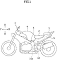
Figure 1 is a side view schematically showing a motorcycle including a seat rail according to an embodiment. -
Figure 2 is a perspective view schematically showing the seat rail according to the embodiment together with a footrest attached to the seat rail. -
Figure 3 is an exploded perspective view schematically showing a left half of the seat rail and the footrest inFigure 2 . -
Figure 4 is a side view schematically showing the seat rail according to the embodiment together with the footrest attached to the seat rail. -
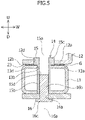
Figure 5 is a cross-sectional view taken along a line A-A inFigure 4 . - A motorcycle seat rail according to an embodiment will be described together with a motorcycle in which the seat rail is installed. Here, the motorcycle in which the seat rail for the motorcycle (hereinafter, simply referred to as a "seat rail" as necessary) is installed includes, typically, one front wheel and one rear wheel. However, the motorcycle may include two front wheels and one rear wheel.
- In
Figures 1 to 4 of the present embodiment, a front of avehicle body 1 of the motorcycle (hereinafter, simply referred to as "front" as necessary) is indicated by a one-headed arrow F, and a rear of the vehicle body 1 (hereinafter, simply referred to as "rear" as necessary) is indicated by a one-headed arrow R. Therefore, a front-rear direction of the vehicle body 1 (hereinafter, simply referred to as a "front-rear direction" as necessary) is indicated by the one-headed arrow F and the one-headed arrow R. InFigures 2 ,3 , and5 , a width direction of the vehicle body 1 (hereinafter, simply referred to as a "width direction" as necessary) is indicated by a two-headed arrow W. InFigures 1 to 5 , an upper side of the vehicle body 1 (hereinafter, simply referred to as an "upper side" as necessary) is indicated by a one-headed arrow U, and a lower side of the vehicle body 1 (hereinafter, simply referred to as a "lower side" as necessary) is indicated by a one-headed arrow D. An up-down direction of the vehicle body 1 (hereinafter, simply referred to as an "up-down direction" as necessary) is indicated by the one-headed arrow U and the one-headed arrow D. - An outline of a
seat rail 10 and the motorcycle according to the present embodiment will be described with reference toFigures 1 to 5 . In other words, theseat rail 10 and the motorcycle are generally configured as follows. As shown inFigure 1 , the seat rail 10 (indicated by a broken line inFigure 1 ) is installed in thevehicle body 1 of the motorcycle. - As shown in
Figure 2 , theseat rail 10 includeslateral member assemblies 11 located at lateral sides in the width direction of thevehicle body 1. Specifically, theseat rail 10 includes twolateral member assemblies 11 located at both lateral sides of thevehicle body 1 in the width direction. The two lateral member assemblies 11 are spaced apart from each other in the width direction. As shown inFigures 2 to 4 , each of thelateral member assemblies 11 includes an upperlateral member 12 made of fiber reinforced resin. The upperlateral member 12 of each of thelateral member assemblies 11 is located at a lateral side in the width direction. - Here, the
seat rail 10 according to the present embodiment is configured such that both of the two lateral member assemblies 11 include components that will be described in detail below. The components of the two lateral member assemblies 11 are substantially symmetrical in the width direction. However, the seat rail may be configured such that only one of the two lateral member assemblies 11 includes the following components. Based on these considerations, in the following, unless the two lateral member assemblies 11 and the components related to the twolateral member assemblies 11 are specifically described, it is assumed that the components of one of the twolateral member assemblies 11 are representatively described. - Referring to
Figures 2 to 5 , each of the upperlateral members 12 includes alower flange 12a protruding in the width direction from a lower edge of the upperlateral member 12. Each of thelateral member assemblies 11 includes a lowerlateral member 13 located below the upperlateral member 12 of thelateral member assembly 11. The lowerlateral member 13 of each of thelateral member assemblies 11 is made of metal. Alower surface 12b of thelower flange 12a of the upperlateral member 12 in each of thelateral member assemblies 11 is joined to anupper surface 13a of the lowerlateral member 13 in such alateral member assembly 11 by an adhesive G. - Furthermore, the
seat rail 10 and the motorcycle according to the present embodiment can be generally configured as follows. Referring toFigures 2 to 5 , each of the lowerlateral members 13 is a hollow member extending from the front to the rear. Afootrest assembly 20 including a footrestmain body 21 and afootrest bracket 22 is attached to each of thelateral member assemblies 11. Specifically, thefootrest bracket 22 of thefootrest assembly 20 is fastened to each of thelateral member assemblies 11. As shown inFigures 3 and5 , theseat rail 10 includes afastening portion 14 configured to fasten together the lowerlateral member 13 of each of thelateral member assembly 11 and thefootrest bracket 22 to be attached to thelateral member assembly 11 using acollar 15 and afastening member 16. - As shown in
Figure 5 , thecollar 15 includes ashaft body part 15b extending along anaxial line 15a thereof. Thecollar 15 further includes ahead part 15c protruding from theshaft body part 15b so as to be away from theaxial line 15a thereof. Thecollar 15 includes afemale screw part 15d formed on theshaft body part 15b so as to extend from a tip to a base end of theshaft body part 15b along theaxial line 15a thereof. The fasteningmember 16 includes amale screw part 16b extending along anaxial line 16a thereof. The fasteningmember 16 further includes ahead part 16c protruding from themale screw part 16b so as to be away from theaxial line 16a thereof. For example, the fasteningmember 16 may be a bolt. However, the fastening member is not limited to the bolt. - The
male screw part 16b of the fasteningmember 16 can be screwed into thefemale screw part 15d of thecollar 15 along theaxial lines collar 15 and the fasteningmember 16 from the tip of theshaft body 15b of thecollar 15. A throughhole 14a is formed in thefastening portion 14 such that theshaft body part 15b of thecollar 15 can be inserted. The throughhole 14a is formed from athrough hole 13b of the lowerlateral member 13 and a throughhole 22a of thefootrest bracket 22. While themale screw part 16b of the fasteningmember 16 is screwed into thefemale screw part 15d of theshaft body part 15b of thecollar 15 inserted into the throughhole 14a of thefastening portion 14, the lowerlateral member 13 and thefootrest bracket 22 are nipped between thehead part 15c of thecollar 15 and thehead part 16c of thefastening member 16. - As shown in
Figures 2 to 4 , theseat rail 10 includes acoupling member 17 extending so as to couple the two upperlateral members 12, which are spaced apart from each other in the width direction, to each other. Thecoupling member 17 includes twolateral edges 17a which are located at both lateral sides in the width direction, respectively. As shown inFigure 4 , when thevehicle body 1 is viewed in the width direction, thefastening portion 14 is overlapped on a region P between afront end 17b and arear end 17c of each of thelateral edge 17a in thecoupling member 17 in the front-rear direction. - Referring to
Figures 1 and2 , the motorcycle according to the present embodiment can be configured in detail as follows. As shown inFigure 1 , thevehicle body 1 of the motorcycle includes aseat 2, aluggage rack 3, and a fuel tank 4. Theseat 2 is supported from below by theseat rail 10. Referring toFigures 1 and2 , theseat 2 is supported from below by thecoupling member 17 of theseat rail 10. - As shown in
Figure 1 , theluggage rack 3 is located behind theseat 2. Theluggage rack 3 is adjacent to theseat 2 in the front-rear direction. The fuel tank 4 is located in front of theseat 2. The fuel tank 4 is adjacent to theseat 2 in the front-rear direction. - The
vehicle body 1 of the motorcycle includes amain frame 5. Themain frame 5 is located in front of theseat rail 10, and is located below the fuel tank 4. Themain frame 5 is adjacent to theseat rail 10 in the front-rear direction. Referring toFigures 1 and2 , afront end part 10a of theseat rail 10 in the front-rear direction is attached to themain frame 5. Specifically,front end parts upper lateral member 12 and the lowerlateral member 13 of theseat rail 10 in the front-rear direction are attached to themain frame 5. - As shown in
Figure 1 , thevehicle body 1 of the motorcycle includes anouter panel 6. Theouter panel 6 is located below theseat 2. Theouter panel 6 is also adjacent to theseat 2 in the up-down direction. Theouter panel 6 covers theseat rail 10 from both outer sides in the width direction. However, the vehicle body may be configured so as not to include the outer panel. In this case, the vehicle body may be configured such that the upper lateral member is exposed to the outside of the vehicle body as an exterior member. - Referring to
Figures 2 to 5 , theseat rail 10 according to the present embodiment can be configured in detail as follows. As shown inFigures 2 to 4 , theseat rail 10 includes anadditional coupling member 18 extending to couple the twoupper lateral members 12 to each other, in addition to thecoupling member 17 described above. Theadditional coupling member 18 is located behind thecoupling member 17. In the following, as necessary, thecoupling member 17 will be referred to as afront coupling member 17, and theadditional coupling member 18 will be referred to as arear coupling member 18. When theseat rail 10 includes a plurality of coupling members, thefront coupling member 17 can be located at the frontmost position among the plurality of coupling members. Therear coupling member 18 can be located at the rearmost position among the plurality of coupling members. - The
front coupling member 17 is located closer to thefront end part 10a of theseat rail 10 in the front-rear direction. As described above, such afront coupling member 17 supports a front part of theseat 2 in the front-rear direction from below. Therear coupling member 18 is located closer to arear end part 10b of theseat rail 10 in the front-rear direction. Therear coupling member 18 can be located to correspond to therear end part 10b of theseat rail 10 in the front-rear direction. Therear coupling member 18 supports a rear part of theseat 2 in the front-rear direction and theluggage rack 3 from below. The front andrear coupling members - The
footrest assembly 20 is configured for a pillion rider. The footrestmain body 21 of thefootrest assembly 20 is formed to protrude outward in the width direction of thevehicle body 1 from a lower end part of thefootrest bracket 22 in the up-down direction. As shown inFigures 2 to 5 , thefootrest bracket 22 includes anattachment portion 22b configured to attach thefootrest bracket 22 to the lowerlateral member 13. Theattachment portion 22b is disposed at an upper end part of thefootrest bracket 22 in the up-down direction. The throughhole 22a of thefootrest bracket 22 described above is formed to penetrate theattachment portion 22b. - As shown in
Figure 3 , each of thelateral member assemblies 11 is provided with the twofastening portions 14 as described above. In this case, the lowerlateral member 13 includes two throughholes 13b, and thefootrest bracket 22 includes two throughholes 22a. Each of thelateral member assemblies 11 includes twocollars 15 and twofastening members 16. Such twofastening portions 14 are spaced apart from each other in the front-rear direction. However, each of the lateral member assemblies may also be provided with one fastening portion or with three or more fastening portions. - Referring to
Figures 2 to 5 , thelateral member assembly 11 can be configured in detail as follows. The fiber reinforced resin used for theupper lateral member 12 of thelateral member assembly 11 is a continuous fiber reinforced resin or a discontinuous fiber reinforced resin. Such a fiber reinforced resin contains a predetermined resin material and a plurality of fibers. - As the resin material of the fiber reinforced resin, a thermoplastic resin or a thermosetting resin can be used. Examples of the thermoplastic resins may include polyamide and polypropylene. Examples of the thermosetting resins may include an epoxy resin and a phenol resin. Examples of the fibers of the fiber reinforced resin may include a carbon fiber, a glass fiber, a polyamide fiber, and a polyethylene fiber. When the fiber reinforced resin is a discontinuous fiber reinforced resin, a length of one fiber may preferably be 10 mm or more from the viewpoint of reinforcement effect. However, the length of one fiber is not limited thereto.
- The
upper lateral member 12 is produced by press-molding of a panel material configured as a laminated structure in which a plurality of layers made of a fiber reinforced resin are laminated. However, the method of producing the upper lateral member is not limited thereto. - As shown in
Figures 3 and5 , thelower flange 12a of theupper lateral member 12 is formed with a throughhole 12d through which thehead part 15c of thecollar 15 can be inserted. The throughhole 12d of thelower flange 12a is disposed to correspond to the throughhole 14a of thefastening portion 14. In particular, thehead part 15c of thecollar 15 is preferably fitted into the throughhole 12d of thelower flange 12a such that theupper lateral member 12 and the lowerlateral member 13 are positioned during the attachment. - As shown in
Figures 2 to 4 , thelower flange 12a of theupper lateral member 12 protrudes toward the center of thevehicle body 1 in the width direction from the lower edge of theupper lateral member 12. Thelower flange 12a is formed in an elongated shape with the front-rear direction being a longitudinal direction. The entirelower surface 12b of thelower flange 12a in theupper lateral member 12 is in contact with theupper surface 13a of the lowerlateral member 13, and is joined to theupper surface 13a of the lowerlateral member 13 by the adhesive G. - The
upper lateral member 12 includes anupper flange 12e protruding in the width direction from the upper edge thereof. Theupper flange 12e of theupper lateral member 12 can also protrude toward the center of thevehicle body 1 in the width direction from the upper edge of theupper lateral member 12. The front andrear coupling members upper surface 12f of theupper flange 12e, and are attached to theupper surface 12f of theupper flange 12e. The lower andupper flanges - A metal used for the lower
lateral member 13 of thelateral member assembly 11 may be selected from aluminum, iron, etc., and alloys thereof. However, the metal used for the lower lateral member is not limited thereto. - As shown in
Figures 2 to 4 , the lowerlateral member 13 is formed in an elongated shape with the front-rear direction being a longitudinal direction. Theupper surface 13a of the lowerlateral member 13 includes acontact area 13d that comes into contact with thelower surface 12b of thelower flange 12a. Thecontact area 13d of the lowerlateral member 13 is formed to correspond to the entirelower surface 12b of thelower flange 12a. Thefront end part 13c of the lowerlateral member 13 protrudes forward from thefront end part 12c of theupper lateral member 12. Thefront end part 13c of the lowerlateral member 13 is located in front of thecontact area 13d of the lowerlateral member 13. - The adhesive G used for the
lateral member assembly 11 may be a synthetic adhesive. Examples of the synthetic adhesive may include an acrylic adhesive, a urethane adhesive, an EVA adhesive, an epoxy adhesive, and other adhesives. However, the adhesives are not limited thereto. - In the
lateral member assembly 11, the adhesive G is applied between thelower surface 12b of thelower flange 12a of theupper lateral member 12 and theupper surface 13a of the lowerlateral member 13, the adhesive G thereby forming anadhesive layer 23. However, the adhesive can also be used on an adhesive tape sandwiched between the lower surface of the lower flange of the upper lateral member and the upper surface of the lower lateral member. - As described above, the
seat rail 10 according to the present embodiment is themotorcycle seat rail 10 installed on thevehicle body 1 of the motorcycle, themotorcycle seat rail 10 including: the upperlateral members 12 located on the lateral sides in the width direction of thevehicle body 1 and made of the fiber reinforced resin, each of the upperlateral members 12 including thelower flange 12a that protrudes in the width direction of thevehicle body 1 from a lower edge of theupper lateral member 12; and the lowerlateral members 13 located downward from the upperlateral members 12 and made of the metal, wherein thelower surfaces 12b of thelower flanges 12a of the upperlateral members 12 are joined to theupper surfaces 13a of the lowerlateral members 13 with the adhesive G. - In such a
seat rail 10, the lowerlateral member 13 made of the metal has increased thermal conductivity, and heat in an internal space of theseat rail 10 is efficiently released from theupper lateral member 12 made of the fiber reinforced resin to the lowerlateral member 13. Therefore, it is possible to prevent heat from being trapped in the internal space of theseat rail 10 and to prevent thermal deterioration of the resin in the fiber reinforced resin forming theupper lateral member 12. As a result, theseat rail 10 can be improved in strength. Furthermore, the lowerlateral member 13 made of the metal has higher strength than theupper lateral member 12 made of the fiber reinforced resin, and thus it is possible to improve strength against compressive deformation of the lower part of theseat rail 10 that may occur when a load is applied to the rear part of theseat rail 10 by ab occupant, luggage, and the like. Therefore, the strength of theseat rail 10 can be efficiently improved. - Furthermore, the
upper lateral member 12 made of the fiber reinforced resin has a higher vibration damping effect than the lowerlateral member 13 made of the metal, and such anupper lateral member 12 is disposed closer to theseat 2 than the lowerlateral member 13 made of the metal, whereby the vibration damping effect of theseat rail 10 can be sufficiently ensured. In addition, since the adhesive G located between thelower surface 12b of thelower flange 12a of theupper lateral member 12 and theupper surface 13a of the lowerlateral member 13 also provides damping performance, the vibration damping effect of theseat rail 10 can be reliably ensured. - In the
seat rail 10 according to the present embodiment, the lowerlateral members 13 are the hollow members extending from the front of thevehicle body 1 toward a rear of thevehicle body 1. Therefore, the damping performance of the lowerlateral member 13 can be improved, and as a result, the vibration damping effect of theseat rail 10 can be reliably ensured. - In the seat rail 10 according to the present embodiment, the fastening portion 14 is provided to fasten the lower lateral member 13 and the footrest bracket 22 using the collar 15 and the fastening member 16, the collar 15 includes the shaft body part 15b extending along the axial line 15a of the collar 15, the head part 15c protruding from the shaft body part 15b so as to be away from the axial line 15a, and the female screw part 15d formed on the shaft body part 15b so as to extend from the tip toward the base end of the shaft body part 15b along the axial line 15a, the fastening member 16 includes the male screw part 16b extending along the axial line 16a of the fastening member 16 and the head part 16c protruding from the male screw part 16b so as to be away from the axial line 16a, the male screw part 16b of the fastening member 16 is capable of being screwed into the female screw part 15d of the collar 15 along the axial lines 15a and 16a of the collar 15 and the fastening member 16 from the tip of the shaft body part 15b of the collar 15, the fastening portion 14 is formed with the through hole 14a into which the shaft body part 15b of the collar 15 is capable of being inserted, and the lower lateral member 13 and the footrest bracket 22 are configured to be sandwiched between the head part 15c of the collar 15 and the head part 16c of the fastening member 16 when the male screw part 16b of the fastening member 16 is screwed into the female screw part 15d of the shaft body part 15b of the collar 15 inserted into the through hole 14a of the fastening portion 14.
- In such a
seat rail 10, thefastening portion 14 can prevent shear deformation in the front-rear direction of the adhesive G caused by the load applied to the rear part of theseat rail 10 by an occupant, luggage, or the like due to, for instance, traveling of a motorcycle on a rough road. Accordingly, the strength of theseat rail 10 can be efficiently improved. In addition, thehead part 15c of thecollar 15 protruding from the lowerlateral member 13 can be used for positioning when theupper lateral member 12 is attached to the lowerlateral member 13. Accordingly, production efficiency of theseat rail 10 can be improved. - The
seat rail 10 according to the present embodiment includes thecoupling member 17 extending to couple the twoupper lateral members 12 spaced apart from each other in the width direction of thevehicle body 1, thecoupling member 17 includes twolateral edges 17a located on both sides in the width direction of thevehicle body 1, and when thevehicle body 1 is viewed in the width direction, thefastening portion 14 overlaps the region P between thefront end 17b and therear end 17c of each of thelateral edges 17a in thecoupling member 17 in the front-rear direction of thevehicle body 1. - In such a
seat rail 10, thecoupling member 17 can prevent the shear deformation in the front-rear direction of the adhesive G caused by a load applied to the rear part of theseat rail 10 by an occupant, luggage, or the like due to traveling of a motorcycle on a rough road, for instance. Accordingly, the strength of theseat rail 10 can be efficiently improved. - Although the embodiment of the present invention has been described above, the present invention is not limited to the above-described embodiment, and the present invention can be modified and changed based on the technical concept thereof.
-
- 1
- vehicle body
- 10
- seat rail
- 12
- upper lateral member
- 12a
- lower flange
- 12b
- lower surface
- 13
- lower lateral member
- 13a
- upper surface
- 14
- fastening portion
- 14a
- through hole
- 15
- collar
- 15a
- axial line
- 15b
- shaft body part
- 15c
- head part
- 15d
- female screw part
- 16
- fastening member
- 16a
- axial line
- 16b
- male screw part
- 16c
- head part
- 17
- coupling member (front coupling member)
- 17a
- lateral edge
- 17b
- front end
- 17c
- rear end
- P
- region
- 22
- footrest bracket
- G
- adhesive
Claims (4)
- A motorcycle seat rail installed on a vehicle body of a motorcycle, the motorcycle seat rail comprising:an upper lateral member located on a lateral side in a width direction of the vehicle body and made of a fiber reinforced resin, the upper lateral member including a lower flange that protrudes in the width direction of the vehicle body from a lower edge of the upper lateral member; anda lower lateral member located downward from the upper lateral member and made of a metal,wherein a lower surface of the lower flange of the upper lateral member is joined to an upper surface of the lower lateral member by an adhesive.
- The motorcycle seat rail according to claim 1, wherein:the lower lateral member is a hollow member extending from a front of the vehicle body toward a rear of the vehicle body.
- The motorcycle seat rail according to claim 1 or 2, wherein:a fastening portion is provided to fasten the lower lateral member and a footrest bracket using a collar and a fastening member;the collar includes a shaft body part extending along an axial line of the collar, a head part protruding from the shaft body part so as to be away from the axial line, and a female screw part formed on the shaft body part so as to extend from a tip toward a base end of the shaft body part along the axial line;the fastening member includes a male screw part extending along an axial line of the fastening member and a head part protruding from the male screw part so as to be away from the axial line;the male screw part of the fastening member is capable of being screwed into the female screw part of the collar along the axial lines of the collar and the fastening member from the tip of the shaft body part of the collar;the fastening portion is formed with a through hole into which the shaft body part of the collar is insertable; andthe lower lateral member and the footrest bracket are configured to be sandwiched between the head part of the collar and the head part of the fastening member when the male screw part of the fastening member is screwed into the female screw part of the shaft body part of the collar inserted into the through hole of the fastening portion.
- The motorcycle seat rail according to claim 3, further comprising:
a coupling member extending to couple two upper lateral members spaced apart from each other in the width direction of the vehicle body, wherein:the coupling member includes two lateral edges located on both sides in the width direction of the vehicle body; andwhen the vehicle body is viewed in the width direction, the fastening portion is overlapped on a region between a front end and a rear end of each of the lateral edges in the coupling member in a front-rear direction of the vehicle body.
Applications Claiming Priority (1)
| Application Number | Priority Date | Filing Date | Title |
|---|---|---|---|
| JP2020175343A JP7571457B2 (en) | 2020-10-19 | 2020-10-19 | Motorcycle seat rails |
Publications (2)
| Publication Number | Publication Date |
|---|---|
| EP3984867A1 true EP3984867A1 (en) | 2022-04-20 |
| EP3984867B1 EP3984867B1 (en) | 2024-08-21 |
Family
ID=78078129
Family Applications (1)
| Application Number | Title | Priority Date | Filing Date |
|---|---|---|---|
| EP21200974.0A Active EP3984867B1 (en) | 2020-10-19 | 2021-10-05 | Motorcycle seat rail |
Country Status (3)
| Country | Link |
|---|---|
| US (1) | US11697464B2 (en) |
| EP (1) | EP3984867B1 (en) |
| JP (1) | JP7571457B2 (en) |
Families Citing this family (3)
| Publication number | Priority date | Publication date | Assignee | Title |
|---|---|---|---|---|
| USD880365S1 (en) * | 2018-07-30 | 2020-04-07 | Harley-Davidson Motor Company Group, LLC | Motorcycle |
| USD880364S1 (en) | 2018-07-30 | 2020-04-07 | Harley-Davidson Motor Company Group, LLC | Motorcycle |
| JP7335549B2 (en) * | 2019-11-28 | 2023-08-30 | スズキ株式会社 | Seat rail structure for motorcycle |
Citations (5)
| Publication number | Priority date | Publication date | Assignee | Title |
|---|---|---|---|---|
| WO2012090848A1 (en) | 2010-12-27 | 2012-07-05 | 東レ株式会社 | Automatic two-wheeled vehicle seat frame |
| US20150060178A1 (en) * | 2013-09-05 | 2015-03-05 | Honda Motor Co., Ltd. | Saddle-ride type vehicle |
| US20160200387A1 (en) * | 2013-09-05 | 2016-07-14 | Honda Motor Co., Ltd. | Vehicle body frame structure for saddled vehicle |
| EP3124363A1 (en) * | 2015-07-30 | 2017-02-01 | Honda Motor Co., Ltd. | Part attachment structure of straddle type vehicle |
| US20180339739A1 (en) * | 2017-05-26 | 2018-11-29 | Suzuki Motor Corporation | Straddle type vehicle |
Family Cites Families (7)
| Publication number | Priority date | Publication date | Assignee | Title |
|---|---|---|---|---|
| JP6502297B2 (en) * | 2016-09-30 | 2019-04-17 | 本田技研工業株式会社 | Saddle-ride type vehicle |
| JP6817823B2 (en) * | 2017-01-18 | 2021-01-20 | 川崎重工業株式会社 | Stay support structure for the frame of a saddle-type vehicle |
| BR112019019312A2 (en) * | 2017-03-30 | 2020-05-05 | Honda Motor Co Ltd | vehicle frame structure of the type vehicle to mount |
| DE112018006250B4 (en) * | 2017-12-08 | 2024-11-28 | Honda Motor Co., Ltd. | VEHICLE FRAME STRUCTURE |
| JP7029996B2 (en) * | 2018-03-28 | 2022-03-04 | 本田技研工業株式会社 | Seat frame structure for saddle-riding vehicles |
| JP7218596B2 (en) * | 2019-02-04 | 2023-02-07 | スズキ株式会社 | Edge structure of fiber reinforced resin structure |
| JP7400376B2 (en) * | 2019-11-15 | 2023-12-19 | スズキ株式会社 | Seat rail structure for motorcycles |
-
2020
- 2020-10-19 JP JP2020175343A patent/JP7571457B2/en active Active
-
2021
- 2021-10-05 EP EP21200974.0A patent/EP3984867B1/en active Active
- 2021-10-13 US US17/499,996 patent/US11697464B2/en active Active
Patent Citations (5)
| Publication number | Priority date | Publication date | Assignee | Title |
|---|---|---|---|---|
| WO2012090848A1 (en) | 2010-12-27 | 2012-07-05 | 東レ株式会社 | Automatic two-wheeled vehicle seat frame |
| US20150060178A1 (en) * | 2013-09-05 | 2015-03-05 | Honda Motor Co., Ltd. | Saddle-ride type vehicle |
| US20160200387A1 (en) * | 2013-09-05 | 2016-07-14 | Honda Motor Co., Ltd. | Vehicle body frame structure for saddled vehicle |
| EP3124363A1 (en) * | 2015-07-30 | 2017-02-01 | Honda Motor Co., Ltd. | Part attachment structure of straddle type vehicle |
| US20180339739A1 (en) * | 2017-05-26 | 2018-11-29 | Suzuki Motor Corporation | Straddle type vehicle |
Also Published As
| Publication number | Publication date |
|---|---|
| US11697464B2 (en) | 2023-07-11 |
| JP2022071222A (en) | 2022-05-16 |
| US20220119059A1 (en) | 2022-04-21 |
| EP3984867B1 (en) | 2024-08-21 |
| JP7571457B2 (en) | 2024-10-23 |
Similar Documents
| Publication | Publication Date | Title |
|---|---|---|
| US11697464B2 (en) | Motorcycle seat rail | |
| US10953941B2 (en) | Straddle type vehicle | |
| JP7247643B2 (en) | motorcycle seat rail | |
| KR101797460B1 (en) | High strength resin cowl cross member and manufacturing method of the same | |
| US12139225B2 (en) | Motorcycle seat rail and method of manufacturing the same | |
| US8894130B2 (en) | Vehicle lower section structure | |
| US20170267290A1 (en) | Automobile vehicle body and automobile vehicle body manufacturing method | |
| CN107922011B (en) | Structural body and structural component including joint structure of dissimilar materials | |
| US20140327290A1 (en) | Frame structure for seat back | |
| US20190329823A1 (en) | Chassis for a vehicle | |
| KR20130129435A (en) | Front vehicle body structure | |
| JP2022071223A (en) | Seat rail structure for motorcycle | |
| US20210163093A1 (en) | Seat Rail Structure For Motorcycle | |
| JP5771019B2 (en) | Vehicle seat back frame structure | |
| KR101393551B1 (en) | Connecting structure for heavy vehicle | |
| US20160194030A1 (en) | Integral longitudinal member for motor vehicles | |
| KR20060009097A (en) | Lower support structure of cowl cross member | |
| JP5840849B2 (en) | Underrun protector stay structure | |
| JP2007269123A (en) | Fastening member for frame structure, frame member, and frame fastening method | |
| US12083975B2 (en) | Bumper beam for a motor vehicle | |
| JP5168214B2 (en) | Car body rear structure | |
| JP7332021B2 (en) | motorcycle seat rail | |
| KR20240056032A (en) | Light-weight center floor module for electric vehicle with multi-material | |
| JP7533210B2 (en) | Plastic roof | |
| CN106573650B (en) | Front part of motor vehicle structure |
Legal Events
| Date | Code | Title | Description |
|---|---|---|---|
| PUAI | Public reference made under article 153(3) epc to a published international application that has entered the european phase |
Free format text: ORIGINAL CODE: 0009012 |
|
| STAA | Information on the status of an ep patent application or granted ep patent |
Free format text: STATUS: REQUEST FOR EXAMINATION WAS MADE |
|
| 17P | Request for examination filed |
Effective date: 20211005 |
|
| AK | Designated contracting states |
Kind code of ref document: A1 Designated state(s): AL AT BE BG CH CY CZ DE DK EE ES FI FR GB GR HR HU IE IS IT LI LT LU LV MC MK MT NL NO PL PT RO RS SE SI SK SM TR |
|
| GRAP | Despatch of communication of intention to grant a patent |
Free format text: ORIGINAL CODE: EPIDOSNIGR1 |
|
| STAA | Information on the status of an ep patent application or granted ep patent |
Free format text: STATUS: GRANT OF PATENT IS INTENDED |
|
| INTG | Intention to grant announced |
Effective date: 20240319 |
|
| GRAJ | Information related to disapproval of communication of intention to grant by the applicant or resumption of examination proceedings by the epo deleted |
Free format text: ORIGINAL CODE: EPIDOSDIGR1 |
|
| STAA | Information on the status of an ep patent application or granted ep patent |
Free format text: STATUS: REQUEST FOR EXAMINATION WAS MADE |
|
| GRAP | Despatch of communication of intention to grant a patent |
Free format text: ORIGINAL CODE: EPIDOSNIGR1 |
|
| STAA | Information on the status of an ep patent application or granted ep patent |
Free format text: STATUS: GRANT OF PATENT IS INTENDED |
|
| INTC | Intention to grant announced (deleted) | ||
| INTG | Intention to grant announced |
Effective date: 20240529 |
|
| GRAS | Grant fee paid |
Free format text: ORIGINAL CODE: EPIDOSNIGR3 |
|
| GRAA | (expected) grant |
Free format text: ORIGINAL CODE: 0009210 |
|
| STAA | Information on the status of an ep patent application or granted ep patent |
Free format text: STATUS: THE PATENT HAS BEEN GRANTED |
|
| AK | Designated contracting states |
Kind code of ref document: B1 Designated state(s): AL AT BE BG CH CY CZ DE DK EE ES FI FR GB GR HR HU IE IS IT LI LT LU LV MC MK MT NL NO PL PT RO RS SE SI SK SM TR |
|
| REG | Reference to a national code |
Ref country code: GB Ref legal event code: FG4D |
|
| REG | Reference to a national code |
Ref country code: CH Ref legal event code: EP |
|
| REG | Reference to a national code |
Ref country code: IE Ref legal event code: FG4D |
|
| REG | Reference to a national code |
Ref country code: DE Ref legal event code: R096 Ref document number: 602021017448 Country of ref document: DE |
|
| REG | Reference to a national code |
Ref country code: LT Ref legal event code: MG9D |
|
| REG | Reference to a national code |
Ref country code: NL Ref legal event code: MP Effective date: 20240821 |
|
| PG25 | Lapsed in a contracting state [announced via postgrant information from national office to epo] |
Ref country code: NO Free format text: LAPSE BECAUSE OF FAILURE TO SUBMIT A TRANSLATION OF THE DESCRIPTION OR TO PAY THE FEE WITHIN THE PRESCRIBED TIME-LIMIT Effective date: 20241121 |
|
| REG | Reference to a national code |
Ref country code: AT Ref legal event code: MK05 Ref document number: 1715262 Country of ref document: AT Kind code of ref document: T Effective date: 20240821 |
|
| PG25 | Lapsed in a contracting state [announced via postgrant information from national office to epo] |
Ref country code: NL Free format text: LAPSE BECAUSE OF FAILURE TO SUBMIT A TRANSLATION OF THE DESCRIPTION OR TO PAY THE FEE WITHIN THE PRESCRIBED TIME-LIMIT Effective date: 20240821 Ref country code: FI Free format text: LAPSE BECAUSE OF FAILURE TO SUBMIT A TRANSLATION OF THE DESCRIPTION OR TO PAY THE FEE WITHIN THE PRESCRIBED TIME-LIMIT Effective date: 20240821 Ref country code: GR Free format text: LAPSE BECAUSE OF FAILURE TO SUBMIT A TRANSLATION OF THE DESCRIPTION OR TO PAY THE FEE WITHIN THE PRESCRIBED TIME-LIMIT Effective date: 20241122 Ref country code: PL Free format text: LAPSE BECAUSE OF FAILURE TO SUBMIT A TRANSLATION OF THE DESCRIPTION OR TO PAY THE FEE WITHIN THE PRESCRIBED TIME-LIMIT Effective date: 20240821 Ref country code: PT Free format text: LAPSE BECAUSE OF FAILURE TO SUBMIT A TRANSLATION OF THE DESCRIPTION OR TO PAY THE FEE WITHIN THE PRESCRIBED TIME-LIMIT Effective date: 20241223 |
|
| PG25 | Lapsed in a contracting state [announced via postgrant information from national office to epo] |
Ref country code: BG Free format text: LAPSE BECAUSE OF FAILURE TO SUBMIT A TRANSLATION OF THE DESCRIPTION OR TO PAY THE FEE WITHIN THE PRESCRIBED TIME-LIMIT Effective date: 20240821 |
|
| PG25 | Lapsed in a contracting state [announced via postgrant information from national office to epo] |
Ref country code: LV Free format text: LAPSE BECAUSE OF FAILURE TO SUBMIT A TRANSLATION OF THE DESCRIPTION OR TO PAY THE FEE WITHIN THE PRESCRIBED TIME-LIMIT Effective date: 20240821 |
|
| PG25 | Lapsed in a contracting state [announced via postgrant information from national office to epo] |
Ref country code: IS Free format text: LAPSE BECAUSE OF FAILURE TO SUBMIT A TRANSLATION OF THE DESCRIPTION OR TO PAY THE FEE WITHIN THE PRESCRIBED TIME-LIMIT Effective date: 20241221 Ref country code: AT Free format text: LAPSE BECAUSE OF FAILURE TO SUBMIT A TRANSLATION OF THE DESCRIPTION OR TO PAY THE FEE WITHIN THE PRESCRIBED TIME-LIMIT Effective date: 20240821 |
|
| PG25 | Lapsed in a contracting state [announced via postgrant information from national office to epo] |
Ref country code: HR Free format text: LAPSE BECAUSE OF FAILURE TO SUBMIT A TRANSLATION OF THE DESCRIPTION OR TO PAY THE FEE WITHIN THE PRESCRIBED TIME-LIMIT Effective date: 20240821 |
|
| PG25 | Lapsed in a contracting state [announced via postgrant information from national office to epo] |
Ref country code: ES Free format text: LAPSE BECAUSE OF FAILURE TO SUBMIT A TRANSLATION OF THE DESCRIPTION OR TO PAY THE FEE WITHIN THE PRESCRIBED TIME-LIMIT Effective date: 20240821 Ref country code: RS Free format text: LAPSE BECAUSE OF FAILURE TO SUBMIT A TRANSLATION OF THE DESCRIPTION OR TO PAY THE FEE WITHIN THE PRESCRIBED TIME-LIMIT Effective date: 20241121 |
|
| PG25 | Lapsed in a contracting state [announced via postgrant information from national office to epo] |
Ref country code: RS Free format text: LAPSE BECAUSE OF FAILURE TO SUBMIT A TRANSLATION OF THE DESCRIPTION OR TO PAY THE FEE WITHIN THE PRESCRIBED TIME-LIMIT Effective date: 20241121 Ref country code: PT Free format text: LAPSE BECAUSE OF FAILURE TO SUBMIT A TRANSLATION OF THE DESCRIPTION OR TO PAY THE FEE WITHIN THE PRESCRIBED TIME-LIMIT Effective date: 20241223 Ref country code: PL Free format text: LAPSE BECAUSE OF FAILURE TO SUBMIT A TRANSLATION OF THE DESCRIPTION OR TO PAY THE FEE WITHIN THE PRESCRIBED TIME-LIMIT Effective date: 20240821 Ref country code: NO Free format text: LAPSE BECAUSE OF FAILURE TO SUBMIT A TRANSLATION OF THE DESCRIPTION OR TO PAY THE FEE WITHIN THE PRESCRIBED TIME-LIMIT Effective date: 20241121 Ref country code: NL Free format text: LAPSE BECAUSE OF FAILURE TO SUBMIT A TRANSLATION OF THE DESCRIPTION OR TO PAY THE FEE WITHIN THE PRESCRIBED TIME-LIMIT Effective date: 20240821 Ref country code: LV Free format text: LAPSE BECAUSE OF FAILURE TO SUBMIT A TRANSLATION OF THE DESCRIPTION OR TO PAY THE FEE WITHIN THE PRESCRIBED TIME-LIMIT Effective date: 20240821 Ref country code: IS Free format text: LAPSE BECAUSE OF FAILURE TO SUBMIT A TRANSLATION OF THE DESCRIPTION OR TO PAY THE FEE WITHIN THE PRESCRIBED TIME-LIMIT Effective date: 20241221 Ref country code: HR Free format text: LAPSE BECAUSE OF FAILURE TO SUBMIT A TRANSLATION OF THE DESCRIPTION OR TO PAY THE FEE WITHIN THE PRESCRIBED TIME-LIMIT Effective date: 20240821 Ref country code: GR Free format text: LAPSE BECAUSE OF FAILURE TO SUBMIT A TRANSLATION OF THE DESCRIPTION OR TO PAY THE FEE WITHIN THE PRESCRIBED TIME-LIMIT Effective date: 20241122 Ref country code: FI Free format text: LAPSE BECAUSE OF FAILURE TO SUBMIT A TRANSLATION OF THE DESCRIPTION OR TO PAY THE FEE WITHIN THE PRESCRIBED TIME-LIMIT Effective date: 20240821 Ref country code: ES Free format text: LAPSE BECAUSE OF FAILURE TO SUBMIT A TRANSLATION OF THE DESCRIPTION OR TO PAY THE FEE WITHIN THE PRESCRIBED TIME-LIMIT Effective date: 20240821 Ref country code: BG Free format text: LAPSE BECAUSE OF FAILURE TO SUBMIT A TRANSLATION OF THE DESCRIPTION OR TO PAY THE FEE WITHIN THE PRESCRIBED TIME-LIMIT Effective date: 20240821 Ref country code: AT Free format text: LAPSE BECAUSE OF FAILURE TO SUBMIT A TRANSLATION OF THE DESCRIPTION OR TO PAY THE FEE WITHIN THE PRESCRIBED TIME-LIMIT Effective date: 20240821 |
|
| PG25 | Lapsed in a contracting state [announced via postgrant information from national office to epo] |
Ref country code: SM Free format text: LAPSE BECAUSE OF FAILURE TO SUBMIT A TRANSLATION OF THE DESCRIPTION OR TO PAY THE FEE WITHIN THE PRESCRIBED TIME-LIMIT Effective date: 20240821 Ref country code: DK Free format text: LAPSE BECAUSE OF FAILURE TO SUBMIT A TRANSLATION OF THE DESCRIPTION OR TO PAY THE FEE WITHIN THE PRESCRIBED TIME-LIMIT Effective date: 20240821 Ref country code: RO Free format text: LAPSE BECAUSE OF FAILURE TO SUBMIT A TRANSLATION OF THE DESCRIPTION OR TO PAY THE FEE WITHIN THE PRESCRIBED TIME-LIMIT Effective date: 20240821 |
|
| PG25 | Lapsed in a contracting state [announced via postgrant information from national office to epo] |
Ref country code: EE Free format text: LAPSE BECAUSE OF FAILURE TO SUBMIT A TRANSLATION OF THE DESCRIPTION OR TO PAY THE FEE WITHIN THE PRESCRIBED TIME-LIMIT Effective date: 20240821 |
|
| PG25 | Lapsed in a contracting state [announced via postgrant information from national office to epo] |
Ref country code: CZ Free format text: LAPSE BECAUSE OF FAILURE TO SUBMIT A TRANSLATION OF THE DESCRIPTION OR TO PAY THE FEE WITHIN THE PRESCRIBED TIME-LIMIT Effective date: 20240821 |
|
| PG25 | Lapsed in a contracting state [announced via postgrant information from national office to epo] |
Ref country code: IT Free format text: LAPSE BECAUSE OF FAILURE TO SUBMIT A TRANSLATION OF THE DESCRIPTION OR TO PAY THE FEE WITHIN THE PRESCRIBED TIME-LIMIT Effective date: 20240821 Ref country code: SK Free format text: LAPSE BECAUSE OF FAILURE TO SUBMIT A TRANSLATION OF THE DESCRIPTION OR TO PAY THE FEE WITHIN THE PRESCRIBED TIME-LIMIT Effective date: 20240821 |
|
| REG | Reference to a national code |
Ref country code: DE Ref legal event code: R097 Ref document number: 602021017448 Country of ref document: DE |
|
| REG | Reference to a national code |
Ref country code: CH Ref legal event code: PL |
|
| PLBE | No opposition filed within time limit |
Free format text: ORIGINAL CODE: 0009261 |
|
| STAA | Information on the status of an ep patent application or granted ep patent |
Free format text: STATUS: NO OPPOSITION FILED WITHIN TIME LIMIT |
|
| PG25 | Lapsed in a contracting state [announced via postgrant information from national office to epo] |
Ref country code: MC Free format text: LAPSE BECAUSE OF FAILURE TO SUBMIT A TRANSLATION OF THE DESCRIPTION OR TO PAY THE FEE WITHIN THE PRESCRIBED TIME-LIMIT Effective date: 20240821 |
|
| PG25 | Lapsed in a contracting state [announced via postgrant information from national office to epo] |
Ref country code: LU Free format text: LAPSE BECAUSE OF NON-PAYMENT OF DUE FEES Effective date: 20241005 Ref country code: BE Free format text: LAPSE BECAUSE OF NON-PAYMENT OF DUE FEES Effective date: 20241031 |
|
| PG25 | Lapsed in a contracting state [announced via postgrant information from national office to epo] |
Ref country code: CH Free format text: LAPSE BECAUSE OF NON-PAYMENT OF DUE FEES Effective date: 20241031 |
|
| 26N | No opposition filed |
Effective date: 20250522 |
|
| REG | Reference to a national code |
Ref country code: BE Ref legal event code: MM Effective date: 20241031 |
|
| PG25 | Lapsed in a contracting state [announced via postgrant information from national office to epo] |
Ref country code: SE Free format text: LAPSE BECAUSE OF FAILURE TO SUBMIT A TRANSLATION OF THE DESCRIPTION OR TO PAY THE FEE WITHIN THE PRESCRIBED TIME-LIMIT Effective date: 20240821 |
|
| PGFP | Annual fee paid to national office [announced via postgrant information from national office to epo] |
Ref country code: FR Payment date: 20250908 Year of fee payment: 5 |
|
| PG25 | Lapsed in a contracting state [announced via postgrant information from national office to epo] |
Ref country code: IE Free format text: LAPSE BECAUSE OF NON-PAYMENT OF DUE FEES Effective date: 20241005 |
|
| PGFP | Annual fee paid to national office [announced via postgrant information from national office to epo] |
Ref country code: DE Payment date: 20250902 Year of fee payment: 5 |
|
| PG25 | Lapsed in a contracting state [announced via postgrant information from national office to epo] |
Ref country code: CY Free format text: LAPSE BECAUSE OF FAILURE TO SUBMIT A TRANSLATION OF THE DESCRIPTION OR TO PAY THE FEE WITHIN THE PRESCRIBED TIME-LIMIT; INVALID AB INITIO Effective date: 20211005 |
|
| PG25 | Lapsed in a contracting state [announced via postgrant information from national office to epo] |
Ref country code: HU Free format text: LAPSE BECAUSE OF FAILURE TO SUBMIT A TRANSLATION OF THE DESCRIPTION OR TO PAY THE FEE WITHIN THE PRESCRIBED TIME-LIMIT; INVALID AB INITIO Effective date: 20211005 |