EP3984805A1 - A method for reducing wear of an energy storage device - Google Patents
A method for reducing wear of an energy storage device Download PDFInfo
- Publication number
- EP3984805A1 EP3984805A1 EP20202042.6A EP20202042A EP3984805A1 EP 3984805 A1 EP3984805 A1 EP 3984805A1 EP 20202042 A EP20202042 A EP 20202042A EP 3984805 A1 EP3984805 A1 EP 3984805A1
- Authority
- EP
- European Patent Office
- Prior art keywords
- energy storage
- load
- electrical energy
- storage device
- energy
- Prior art date
- Legal status (The legal status is an assumption and is not a legal conclusion. Google has not performed a legal analysis and makes no representation as to the accuracy of the status listed.)
- Granted
Links
Images


Classifications
-
- B—PERFORMING OPERATIONS; TRANSPORTING
- B60—VEHICLES IN GENERAL
- B60L—PROPULSION OF ELECTRICALLY-PROPELLED VEHICLES; SUPPLYING ELECTRIC POWER FOR AUXILIARY EQUIPMENT OF ELECTRICALLY-PROPELLED VEHICLES; ELECTRODYNAMIC BRAKE SYSTEMS FOR VEHICLES IN GENERAL; MAGNETIC SUSPENSION OR LEVITATION FOR VEHICLES; MONITORING OPERATING VARIABLES OF ELECTRICALLY-PROPELLED VEHICLES; ELECTRIC SAFETY DEVICES FOR ELECTRICALLY-PROPELLED VEHICLES
- B60L1/00—Supplying electric power to auxiliary equipment of vehicles
- B60L1/02—Supplying electric power to auxiliary equipment of vehicles to electric heating circuits
- B60L1/04—Supplying electric power to auxiliary equipment of vehicles to electric heating circuits fed by the power supply line
- B60L1/06—Supplying electric power to auxiliary equipment of vehicles to electric heating circuits fed by the power supply line using only one supply
-
- B—PERFORMING OPERATIONS; TRANSPORTING
- B60—VEHICLES IN GENERAL
- B60L—PROPULSION OF ELECTRICALLY-PROPELLED VEHICLES; SUPPLYING ELECTRIC POWER FOR AUXILIARY EQUIPMENT OF ELECTRICALLY-PROPELLED VEHICLES; ELECTRODYNAMIC BRAKE SYSTEMS FOR VEHICLES IN GENERAL; MAGNETIC SUSPENSION OR LEVITATION FOR VEHICLES; MONITORING OPERATING VARIABLES OF ELECTRICALLY-PROPELLED VEHICLES; ELECTRIC SAFETY DEVICES FOR ELECTRICALLY-PROPELLED VEHICLES
- B60L3/00—Electric devices on electrically-propelled vehicles for safety purposes; Monitoring operating variables, e.g. speed, deceleration or energy consumption
- B60L3/0023—Detecting, eliminating, remedying or compensating for drive train abnormalities, e.g. failures within the drive train
- B60L3/0046—Detecting, eliminating, remedying or compensating for drive train abnormalities, e.g. failures within the drive train relating to electric energy storage systems, e.g. batteries or capacitors
-
- H—ELECTRICITY
- H02—GENERATION; CONVERSION OR DISTRIBUTION OF ELECTRIC POWER
- H02J—ELECTRIC POWER NETWORKS; CIRCUIT ARRANGEMENTS OR SYSTEMS FOR SUPPLYING OR DISTRIBUTING ELECTRIC POWER; SYSTEMS FOR STORING ELECTRIC ENERGY
- H02J7/00—Circuit arrangements for charging or discharging batteries or for supplying loads from batteries
- H02J7/50—Circuit arrangements for charging or discharging batteries or for supplying loads from batteries acting upon multiple batteries simultaneously or sequentially
-
- B—PERFORMING OPERATIONS; TRANSPORTING
- B60—VEHICLES IN GENERAL
- B60L—PROPULSION OF ELECTRICALLY-PROPELLED VEHICLES; SUPPLYING ELECTRIC POWER FOR AUXILIARY EQUIPMENT OF ELECTRICALLY-PROPELLED VEHICLES; ELECTRODYNAMIC BRAKE SYSTEMS FOR VEHICLES IN GENERAL; MAGNETIC SUSPENSION OR LEVITATION FOR VEHICLES; MONITORING OPERATING VARIABLES OF ELECTRICALLY-PROPELLED VEHICLES; ELECTRIC SAFETY DEVICES FOR ELECTRICALLY-PROPELLED VEHICLES
- B60L3/00—Electric devices on electrically-propelled vehicles for safety purposes; Monitoring operating variables, e.g. speed, deceleration or energy consumption
-
- B—PERFORMING OPERATIONS; TRANSPORTING
- B60—VEHICLES IN GENERAL
- B60L—PROPULSION OF ELECTRICALLY-PROPELLED VEHICLES; SUPPLYING ELECTRIC POWER FOR AUXILIARY EQUIPMENT OF ELECTRICALLY-PROPELLED VEHICLES; ELECTRODYNAMIC BRAKE SYSTEMS FOR VEHICLES IN GENERAL; MAGNETIC SUSPENSION OR LEVITATION FOR VEHICLES; MONITORING OPERATING VARIABLES OF ELECTRICALLY-PROPELLED VEHICLES; ELECTRIC SAFETY DEVICES FOR ELECTRICALLY-PROPELLED VEHICLES
- B60L50/00—Electric propulsion with power supplied within the vehicle
- B60L50/50—Electric propulsion with power supplied within the vehicle using propulsion power supplied by batteries or fuel cells
- B60L50/60—Electric propulsion with power supplied within the vehicle using propulsion power supplied by batteries or fuel cells using power supplied by batteries
-
- B—PERFORMING OPERATIONS; TRANSPORTING
- B60—VEHICLES IN GENERAL
- B60L—PROPULSION OF ELECTRICALLY-PROPELLED VEHICLES; SUPPLYING ELECTRIC POWER FOR AUXILIARY EQUIPMENT OF ELECTRICALLY-PROPELLED VEHICLES; ELECTRODYNAMIC BRAKE SYSTEMS FOR VEHICLES IN GENERAL; MAGNETIC SUSPENSION OR LEVITATION FOR VEHICLES; MONITORING OPERATING VARIABLES OF ELECTRICALLY-PROPELLED VEHICLES; ELECTRIC SAFETY DEVICES FOR ELECTRICALLY-PROPELLED VEHICLES
- B60L53/00—Methods of charging batteries, specially adapted for electric vehicles; Charging stations or on-board charging equipment therefor; Exchange of energy storage elements in electric vehicles
-
- B—PERFORMING OPERATIONS; TRANSPORTING
- B60—VEHICLES IN GENERAL
- B60L—PROPULSION OF ELECTRICALLY-PROPELLED VEHICLES; SUPPLYING ELECTRIC POWER FOR AUXILIARY EQUIPMENT OF ELECTRICALLY-PROPELLED VEHICLES; ELECTRODYNAMIC BRAKE SYSTEMS FOR VEHICLES IN GENERAL; MAGNETIC SUSPENSION OR LEVITATION FOR VEHICLES; MONITORING OPERATING VARIABLES OF ELECTRICALLY-PROPELLED VEHICLES; ELECTRIC SAFETY DEVICES FOR ELECTRICALLY-PROPELLED VEHICLES
- B60L58/00—Methods or circuit arrangements for monitoring or controlling batteries or fuel cells, specially adapted for electric vehicles
-
- B—PERFORMING OPERATIONS; TRANSPORTING
- B60—VEHICLES IN GENERAL
- B60L—PROPULSION OF ELECTRICALLY-PROPELLED VEHICLES; SUPPLYING ELECTRIC POWER FOR AUXILIARY EQUIPMENT OF ELECTRICALLY-PROPELLED VEHICLES; ELECTRODYNAMIC BRAKE SYSTEMS FOR VEHICLES IN GENERAL; MAGNETIC SUSPENSION OR LEVITATION FOR VEHICLES; MONITORING OPERATING VARIABLES OF ELECTRICALLY-PROPELLED VEHICLES; ELECTRIC SAFETY DEVICES FOR ELECTRICALLY-PROPELLED VEHICLES
- B60L58/00—Methods or circuit arrangements for monitoring or controlling batteries or fuel cells, specially adapted for electric vehicles
- B60L58/10—Methods or circuit arrangements for monitoring or controlling batteries or fuel cells, specially adapted for electric vehicles for monitoring or controlling batteries
- B60L58/12—Methods or circuit arrangements for monitoring or controlling batteries or fuel cells, specially adapted for electric vehicles for monitoring or controlling batteries responding to state of charge [SoC]
-
- B—PERFORMING OPERATIONS; TRANSPORTING
- B60—VEHICLES IN GENERAL
- B60L—PROPULSION OF ELECTRICALLY-PROPELLED VEHICLES; SUPPLYING ELECTRIC POWER FOR AUXILIARY EQUIPMENT OF ELECTRICALLY-PROPELLED VEHICLES; ELECTRODYNAMIC BRAKE SYSTEMS FOR VEHICLES IN GENERAL; MAGNETIC SUSPENSION OR LEVITATION FOR VEHICLES; MONITORING OPERATING VARIABLES OF ELECTRICALLY-PROPELLED VEHICLES; ELECTRIC SAFETY DEVICES FOR ELECTRICALLY-PROPELLED VEHICLES
- B60L58/00—Methods or circuit arrangements for monitoring or controlling batteries or fuel cells, specially adapted for electric vehicles
- B60L58/10—Methods or circuit arrangements for monitoring or controlling batteries or fuel cells, specially adapted for electric vehicles for monitoring or controlling batteries
- B60L58/18—Methods or circuit arrangements for monitoring or controlling batteries or fuel cells, specially adapted for electric vehicles for monitoring or controlling batteries of two or more battery modules
- B60L58/20—Methods or circuit arrangements for monitoring or controlling batteries or fuel cells, specially adapted for electric vehicles for monitoring or controlling batteries of two or more battery modules having different nominal voltages
-
- B—PERFORMING OPERATIONS; TRANSPORTING
- B60—VEHICLES IN GENERAL
- B60L—PROPULSION OF ELECTRICALLY-PROPELLED VEHICLES; SUPPLYING ELECTRIC POWER FOR AUXILIARY EQUIPMENT OF ELECTRICALLY-PROPELLED VEHICLES; ELECTRODYNAMIC BRAKE SYSTEMS FOR VEHICLES IN GENERAL; MAGNETIC SUSPENSION OR LEVITATION FOR VEHICLES; MONITORING OPERATING VARIABLES OF ELECTRICALLY-PROPELLED VEHICLES; ELECTRIC SAFETY DEVICES FOR ELECTRICALLY-PROPELLED VEHICLES
- B60L58/00—Methods or circuit arrangements for monitoring or controlling batteries or fuel cells, specially adapted for electric vehicles
- B60L58/10—Methods or circuit arrangements for monitoring or controlling batteries or fuel cells, specially adapted for electric vehicles for monitoring or controlling batteries
- B60L58/18—Methods or circuit arrangements for monitoring or controlling batteries or fuel cells, specially adapted for electric vehicles for monitoring or controlling batteries of two or more battery modules
- B60L58/21—Methods or circuit arrangements for monitoring or controlling batteries or fuel cells, specially adapted for electric vehicles for monitoring or controlling batteries of two or more battery modules having the same nominal voltage
-
- B—PERFORMING OPERATIONS; TRANSPORTING
- B60—VEHICLES IN GENERAL
- B60L—PROPULSION OF ELECTRICALLY-PROPELLED VEHICLES; SUPPLYING ELECTRIC POWER FOR AUXILIARY EQUIPMENT OF ELECTRICALLY-PROPELLED VEHICLES; ELECTRODYNAMIC BRAKE SYSTEMS FOR VEHICLES IN GENERAL; MAGNETIC SUSPENSION OR LEVITATION FOR VEHICLES; MONITORING OPERATING VARIABLES OF ELECTRICALLY-PROPELLED VEHICLES; ELECTRIC SAFETY DEVICES FOR ELECTRICALLY-PROPELLED VEHICLES
- B60L58/00—Methods or circuit arrangements for monitoring or controlling batteries or fuel cells, specially adapted for electric vehicles
- B60L58/10—Methods or circuit arrangements for monitoring or controlling batteries or fuel cells, specially adapted for electric vehicles for monitoring or controlling batteries
- B60L58/18—Methods or circuit arrangements for monitoring or controlling batteries or fuel cells, specially adapted for electric vehicles for monitoring or controlling batteries of two or more battery modules
- B60L58/22—Balancing the charge of battery modules
-
- B—PERFORMING OPERATIONS; TRANSPORTING
- B60—VEHICLES IN GENERAL
- B60L—PROPULSION OF ELECTRICALLY-PROPELLED VEHICLES; SUPPLYING ELECTRIC POWER FOR AUXILIARY EQUIPMENT OF ELECTRICALLY-PROPELLED VEHICLES; ELECTRODYNAMIC BRAKE SYSTEMS FOR VEHICLES IN GENERAL; MAGNETIC SUSPENSION OR LEVITATION FOR VEHICLES; MONITORING OPERATING VARIABLES OF ELECTRICALLY-PROPELLED VEHICLES; ELECTRIC SAFETY DEVICES FOR ELECTRICALLY-PROPELLED VEHICLES
- B60L58/00—Methods or circuit arrangements for monitoring or controlling batteries or fuel cells, specially adapted for electric vehicles
- B60L58/40—Methods or circuit arrangements for monitoring or controlling batteries or fuel cells, specially adapted for electric vehicles for controlling a combination of batteries and fuel cells
-
- H—ELECTRICITY
- H02—GENERATION; CONVERSION OR DISTRIBUTION OF ELECTRIC POWER
- H02J—ELECTRIC POWER NETWORKS; CIRCUIT ARRANGEMENTS OR SYSTEMS FOR SUPPLYING OR DISTRIBUTING ELECTRIC POWER; SYSTEMS FOR STORING ELECTRIC ENERGY
- H02J7/00—Circuit arrangements for charging or discharging batteries or for supplying loads from batteries
- H02J7/50—Circuit arrangements for charging or discharging batteries or for supplying loads from batteries acting upon multiple batteries simultaneously or sequentially
- H02J7/585—Sequential battery discharge in systems with a plurality of batteries
-
- H—ELECTRICITY
- H02—GENERATION; CONVERSION OR DISTRIBUTION OF ELECTRIC POWER
- H02J—ELECTRIC POWER NETWORKS; CIRCUIT ARRANGEMENTS OR SYSTEMS FOR SUPPLYING OR DISTRIBUTING ELECTRIC POWER; SYSTEMS FOR STORING ELECTRIC ENERGY
- H02J7/00—Circuit arrangements for charging or discharging batteries or for supplying loads from batteries
- H02J7/855—Circuit arrangements for charging or discharging batteries or for supplying loads from batteries with circuits adapted for supplying loads from the battery
-
- H—ELECTRICITY
- H02—GENERATION; CONVERSION OR DISTRIBUTION OF ELECTRIC POWER
- H02J—ELECTRIC POWER NETWORKS; CIRCUIT ARRANGEMENTS OR SYSTEMS FOR SUPPLYING OR DISTRIBUTING ELECTRIC POWER; SYSTEMS FOR STORING ELECTRIC ENERGY
- H02J7/00—Circuit arrangements for charging or discharging batteries or for supplying loads from batteries
- H02J7/875—Charging or discharging for charge maintenance, battery initiation or rejuvenation
-
- B—PERFORMING OPERATIONS; TRANSPORTING
- B60—VEHICLES IN GENERAL
- B60L—PROPULSION OF ELECTRICALLY-PROPELLED VEHICLES; SUPPLYING ELECTRIC POWER FOR AUXILIARY EQUIPMENT OF ELECTRICALLY-PROPELLED VEHICLES; ELECTRODYNAMIC BRAKE SYSTEMS FOR VEHICLES IN GENERAL; MAGNETIC SUSPENSION OR LEVITATION FOR VEHICLES; MONITORING OPERATING VARIABLES OF ELECTRICALLY-PROPELLED VEHICLES; ELECTRIC SAFETY DEVICES FOR ELECTRICALLY-PROPELLED VEHICLES
- B60L2200/00—Type of vehicles
- B60L2200/36—Vehicles designed to transport cargo, e.g. trucks
-
- H—ELECTRICITY
- H02—GENERATION; CONVERSION OR DISTRIBUTION OF ELECTRIC POWER
- H02J—ELECTRIC POWER NETWORKS; CIRCUIT ARRANGEMENTS OR SYSTEMS FOR SUPPLYING OR DISTRIBUTING ELECTRIC POWER; SYSTEMS FOR STORING ELECTRIC ENERGY
- H02J2105/00—Networks for supplying or distributing electric power characterised by their spatial reach or by the load
- H02J2105/30—Networks for supplying or distributing electric power characterised by their spatial reach or by the load the load networks being external to vehicles, i.e. exchanging power with vehicles
- H02J2105/33—Networks for supplying or distributing electric power characterised by their spatial reach or by the load the load networks being external to vehicles, i.e. exchanging power with vehicles exchanging power with road vehicles
-
- Y—GENERAL TAGGING OF NEW TECHNOLOGICAL DEVELOPMENTS; GENERAL TAGGING OF CROSS-SECTIONAL TECHNOLOGIES SPANNING OVER SEVERAL SECTIONS OF THE IPC; TECHNICAL SUBJECTS COVERED BY FORMER USPC CROSS-REFERENCE ART COLLECTIONS [XRACs] AND DIGESTS
- Y02—TECHNOLOGIES OR APPLICATIONS FOR MITIGATION OR ADAPTATION AGAINST CLIMATE CHANGE
- Y02T—CLIMATE CHANGE MITIGATION TECHNOLOGIES RELATED TO TRANSPORTATION
- Y02T10/00—Road transport of goods or passengers
- Y02T10/60—Other road transportation technologies with climate change mitigation effect
- Y02T10/70—Energy storage systems for electromobility, e.g. batteries
-
- Y—GENERAL TAGGING OF NEW TECHNOLOGICAL DEVELOPMENTS; GENERAL TAGGING OF CROSS-SECTIONAL TECHNOLOGIES SPANNING OVER SEVERAL SECTIONS OF THE IPC; TECHNICAL SUBJECTS COVERED BY FORMER USPC CROSS-REFERENCE ART COLLECTIONS [XRACs] AND DIGESTS
- Y02—TECHNOLOGIES OR APPLICATIONS FOR MITIGATION OR ADAPTATION AGAINST CLIMATE CHANGE
- Y02T—CLIMATE CHANGE MITIGATION TECHNOLOGIES RELATED TO TRANSPORTATION
- Y02T10/00—Road transport of goods or passengers
- Y02T10/60—Other road transportation technologies with climate change mitigation effect
- Y02T10/7072—Electromobility specific charging systems or methods for batteries, ultracapacitors, supercapacitors or double-layer capacitors
-
- Y—GENERAL TAGGING OF NEW TECHNOLOGICAL DEVELOPMENTS; GENERAL TAGGING OF CROSS-SECTIONAL TECHNOLOGIES SPANNING OVER SEVERAL SECTIONS OF THE IPC; TECHNICAL SUBJECTS COVERED BY FORMER USPC CROSS-REFERENCE ART COLLECTIONS [XRACs] AND DIGESTS
- Y02—TECHNOLOGIES OR APPLICATIONS FOR MITIGATION OR ADAPTATION AGAINST CLIMATE CHANGE
- Y02T—CLIMATE CHANGE MITIGATION TECHNOLOGIES RELATED TO TRANSPORTATION
- Y02T90/00—Enabling technologies or technologies with a potential or indirect contribution to GHG emissions mitigation
- Y02T90/10—Technologies relating to charging of electric vehicles
- Y02T90/14—Plug-in electric vehicles
Definitions
- the present invention relates to a method for reducing wear of an energy storage device in an energy storage system.
- the invention further relates to a switching arrangement, a power conditioning arrangement, and to an electric vehicle.
- a vehicle typically comprises an engine or machine for propelling the vehicle.
- the engine may be powered by various means, such as e.g. by a liquid or gaseous fuel in an internal combustion engine, or by electric power to an electric machine.
- hybrid solutions exist in which e.g. the vehicle is propelled both by an internal combustion engine and an electric machine. In either way, an energy storage device is used to store the energy needed in order to propel the vehicle. Energy storage devices may further be used to power auxiliary loads in the vehicle.
- the energy storage devices are comprised in an energy storage system, wherein the energy storage system is configured to power and engine or machine for propelling the vehicle, as well as an auxiliary load.
- the energy storage devices are typically batteries, which are configured to operate the electric machine as well as electrically driven auxiliary equipment.
- the batteries are periodically in need of charging, and is then electrically connected to an electrical energy source.
- One common solution to charge the batteries is by a plug connected to the electrical energy source, e.g. a power source such as a power grid, by an electrical wire or cable.
- the vehicle is parked in a parking/charging spot providing such charging means, and the driver or other person manually plug the charging means into a socket of the vehicle, the socket being in electrical communication with the energy storage system and the batteries enabling charging of the same.
- a wireless charging system utilizing a power emitting coil and a power receiving coil configured to receive emitted electromagnetic radiation from the power emitting coil.
- an auxiliary load of the vehicle may be in need of powering.
- the auxiliary load may then be directly connected to the electrical energy source and operated by power from e.g. the power grid.
- the system is not particularly robust to load changes.
- a method for reducing wear of an energy storage device in an energy storage system connected to a load, the energy storage system comprising at least two energy storage devices comprising:
- At least one energy storage device is not active during powering of the load, and is thus not subject to any wear, while the energy storage system provides stable conditions for powering the load as at least one of the energy storage devices is used as buffer or load buffer in the system.
- the wear of the energy storage device which is not active during powering of the load is reduced.
- one, or at least one, energy storage device is connected or is active in powering the load, and one energy storage device is disconnected or inactive in powering the load, wherein the wear of the latter may be reduced.
- the electrical energy source is electrically powering the load via the energy storage system in such a way that at least one energy storage device is active, and at least one energy storage device is inactive. This provides for a robust system with regards to load changes, with a minimized wear of the energy storage devices.
- the wear which is reduced may e.g. be contactor wear.
- At least one energy storage device which is active in powering the load is used to provide an improved stability in the energy storage system (i.e. to function as a type of buffer or load buffer).
- the energy storage system comprises an energy source interface, which energy source interface is connectable to the electrical energy source and each one of the energy storage devices.
- the energy source interface is active in connecting the electrical energy source with the energy storage devices (whichever is active and/or is charging).
- the energy storage system comprises a load interface, which load interface is connectable to the load and each one of the energy storage devices.
- the load interface is active in connecting the energy storage devices (whichever is active) with the load.
- the method comprises: alternately connecting and disconnecting the at least two energy storage devices.
- At least one of the energy storage devices will not be active, and thus not subject to any wear. That is, connecting at least a first energy storage device to transfer electrical energy from the energy source to the load, and disconnecting at least a second energy storage device to not transfer electrical energy from the energy source to the load, and subsequently alternating the connection/disconnection such that the first energy storage device is disconnected and the second energy storage device is connected.
- the step of alternately connecting and disconnecting the at least two energy storage devices may be performed during the step of electrically powering the load, or between two such steps of electrically powering the load.
- the energy storage system comprises a plurality of energy storage devices, the plurality being more than two, and the method further comprises: connecting the energy storage device which has been disconnected the longest time.
- the overall wear of the energy storage devices can be reduced in an effective manner.
- the wear may be related to the number of a times an energy storage device is connected, and it is thus efficient to ensure that each energy storage device is connected/disconnected the same number of times.
- the energy storage system comprises three energy storage devices
- a first energy storage device is connected (i.e. is active) while a second and third energy storage devices are disconnected (i.e. are inactive);
- the second energy storage device is connected (i.e. is active) while the first and third energy storage devices are disconnected (i.e.
- the method comprises subsequently connecting and disconnecting the energy storage devices according to a scheme in which the energy storage that was first connected, is reconnected once the all of the energy storage devices have been connected one time.
- the method comprises: cycling the energy storage devices in the energy storage system in such a way that over time, each energy storage device is connected for transferring electrical energy from the electrical energy source to the load roughly the same amount of time.
- the wear may be related to the elapsed time which said energy storage device has been connected, and it is thus efficient to ensure that each energy storage device is connected/disconnected the same amount of time. It should be understood that the energy storage devices need not to be connected exactly the same amount of time, but roughly the same amount of time may. For example, over time, e.g. 10 days, or 30 days, or 300 days, no energy storage device has been connected a total time of more than 10 %, or more than 5 % compared to any other energy storage device in the energy storage system.
- the energy storage devices may be connected the same number of times, as well as roughly the same amount of time. It should be noted that by using such cycling of the energy storage devices, it does not matter if an individual energy storage device is connected in two subsequent steps of electrically powering the load (i.e. is connected once, and directly thereafter re-connected), or if a certain energy storage device for some reason is temporarily unavailable and not included in the alternatively connecting and disconnecting activities, as over time, such connection inequalities may be evened out, with the result that each energy storage device is connected roughly the same amount of time.
- the method comprises: remembering which energy storage device that was previously connected for transferring electrical energy from the electrical energy source to the load, upon a subsequent step of electrically powering the load via the electrical energy storage system, connecting another energy storage device for transferring electrical energy from the electrical energy source to the load than the energy storage device previously used.
- only one energy storage device of the energy storage system is connected for transferring electrical energy from the electrical energy source to the load, and any other energy storage devices of the energy storage system is disconnected and is not transferring any electrical energy from the electrical energy source to the load.
- the overall wear of the energy storage devices can be reduced in an effective manner.
- the previously mentioned buffer or load buffer is provided, while the wear is minimized or reduced.
- the other two are disconnected.
- the at least one energy storage device connected for transferring electrical energy from the electrical energy source to the load is not charging.
- At least one energy storage device connected for transferring electrical energy from the electrical energy source to the load is charging.
- the at least one energy storage device disconnected to not transfer any electrical energy from the electrical energy source to the load is not charging.
- such energy storage device may be considered at rest, and is thus disconnected from both the electrical energy source and the load.
- at least one energy storage device disconnected to not transfer any electrical energy from the electrical energy source to the load is charging.
- an energy storage device which is not used as buffer or load buffer, may be charged. This provides an efficient use of the downtime of the energy storage devices.
- a switching arrangement for reducing wear of an energy storage device in an energy storage system connectable to an electrical energy source and to a load, the energy storage system comprising at least two energy storage devices.
- the switching arrangement is configured to electrically connect and disconnect each of the energy storage devices to the electrical energy source and/or the load, wherein the switching arrangement is configured to electrically power the load via the energy storage system in such a way that at least one energy storage device is connected for transferring electrical energy from the electrical energy source to the load, and at least one other energy storage device is disconnected and is not transferring any electrical energy.
- the switching arrangement is configured to perform the steps of the method of the first aspect of the invention by connecting at least one of the energy storage devices to transfer electrical energy from the energy source to the load (i.e. that energy storage device being active), and disconnecting at least one other energy storage device to not transfer any electrical energy from the energy source to the load (i.e. that energy storage device being not active or inactive).
- at least one energy storage device is not active during powering of the load, and is thus not subject to any wear.
- the switching arrangement is configured to alternately connect and disconnect the at least two energy storage devices.
- the switching arrangement may e.g. comprise at least one contactor for each energy storage device.
- the energy storage system comprises a plurality of energy storage devices, the plurality being more than two, and the switching arrangement is configured to connect the energy storage device which has been disconnected the longest time.
- the switching arrangement is configured to cycle the energy storage devices in the energy storage system in such a way that over time, each energy storage device is connected for transferring electrical energy from the electrical energy source to the load roughly the same amount of time.
- the switching arrangement is configured to remember which energy storage device that was previously connected for transferring electrical energy from the energy source to the load, and upon a subsequent action of electrically powering the load via the electrical energy storage system, to connect another energy storage device to transfer electrical energy from the energy source to the load than the energy storage device previously used.
- the switching arrangement may e.g. comprise a physical memory, or be communicatively connected to such physical memory.
- the switching arrangement is configured to enable only one energy storage device of the energy storage system to be connected for transferring electrical energy from the electrical energy source to the load, and any other energy storage devices of the energy storage system to be disconnected and thus not transferring any electrical energy from the electrical energy source to the load.
- the switching arrangement may e.g. be equipped with a processing unit, processing information concerning which energy storage device to connect, and which to disconnect (e.g. provided by a physical memory).
- a processing unit processing information concerning which energy storage device to connect, and which to disconnect (e.g. provided by a physical memory).
- a power conditioning arrangement comprises:
- the energy storage system comprises a plurality of energy storage devices, the plurality being more than two.
- the energy storage system may comprise at least three energy storage devices.
- the energy storage system comprises an energy source interface, which energy source interface is connectable to the electrical energy source and each one of the energy storage devices.
- the energy source interface is active in connecting the electrical energy source with the energy storage devices (whichever is active and/or is charging).
- the energy storage system comprises a load interface, which load interface is connectable to the load and each one of the energy storage devices.
- the load interface is active in connecting the energy storage devices (whichever is active) with the load.
- an electric vehicle comprises a switching arrangement according the second aspect of the invention, or a power conditioning arrangement according to the second aspect of the invention.
- a computer program comprising program code means for performing the method of the first aspect of the invention, when the program is run on a computer.
- Such computer program may e.g. be implemented in an ECU of the vehicle, or e.g. be comprised in a control unit of the switching arrangement.
- a computer readable medium carrying a computer program comprising program code means for performing the method of the first aspect of the invention, when the program product is run on a computer, is provided.
- the energy storage devices are batteries, e.g. batteries adapted for a vehicle, such as e.g. a heavy duty truck.
- a vehicle 1, here embodied as a heavy duty truck 1, for which a method, switching arrangement 15, and/or a power conditioning arrangement 10 of a kind disclosed in the present invention is advantageous.
- the method, switching arrangement 15 or power conditioning arrangement 10 may as well be implemented in other types of vehicles, such as in busses, light-weight trucks, passenger cars, marine applications etc.
- the vehicle 1 is an electric vehicle, such as a full electric vehicle or a hybrid, comprising at least one electric machine 20, an energy storage system 30 comprising three energy storage devices 31, 32, 33, typically batteries, the energy storage system 30 being arranged and configured to power the electric machine 20.
- the vehicle 1 comprises an auxiliary load 40 arranged and configured for being powered by the energy storage system 30, the auxiliary load 40 being e.g. a heater.
- the energy storage system 30 is arranged and configured to supply at least two different loads 20, 40 with electric power, the first load being the electric machine 20, and the second load being the auxiliary load 40.
- the vehicle 1 typically further comprises other parts of the powertrain such as transmission, drive shafts and wheels (not shown in detail).
- the energy storage system 30 is connected to an electrical energy source 80 via an energy transfer means 90, typically a cable for transferring electrical energy to the three energy storage devices 31, 32, 33.
- the energy storage devices 31, 32, 33 may be charged with electrical energy.
- any one of the loads such as e.g. the auxiliary load 40, may be powered directly via the electrical energy source 80.
- the electric energy is preferably transferred via at least one of the energy storage devices 31, 32, 33 in order to provide an improved stability in the system (i.e. a type of buffer or load buffer).
- a switching arrangement 15 e.g. by a functionality comprised in a control unit of the switching arrangement 15, as will be described in the following.
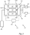
- Fig. 2 is a schematic view of a power conditioning arrangement 110 comprising an energy storage system 130 and a switching arrangement 115.
- the energy storage system 130 is connected to two loads being e.g. an electric machine 120 and an auxiliary load 140 arranged and configured for being powered by the energy storage system 130, and connected to an electrical energy source 180 supplying electrical energy to the energy storage system 130.
- the energy storage system 130 comprises three energy storage devices 131, 132, 133 arranged in a parallel configuration, an energy source interface 134 providing an interface of the three energy storage devices 131, 132, 133 with the electrical energy source 180, and a load interface 136 providing an interface of the three energy storage devices 131, 132, 133 with each one of the two loads 120, 140.
- each one of the energy storage devices 131, 132, 133 comprises a respective first contactor 131A, 132A, 133A for connection to the energy source interface 134 and the electrical energy source 180, and a respective second contactor 131B, 132B, 133B for connection to the load interface 136 and the loads 120, 140.
- the contactors 131A, 132A, 133A, 131B, 132B, 133B are only schematically illustrated as boxes in Fig. 2 , and may according to at least one example embodiment form for the energy source interface 134, and the load interface 136, respectively.
- the first contactors 131A, 132A, 133A may form the energy source interface and the second contactors 131B, 132B, 133B may form the load interface.
- the contactors 131A, 132A, 133A, 131B, 132B, 133B may e.g. be arcing contactors or circuit breakers or another type of switches.
- the switching arrangement 115 comprises a control unit 116, and is arranged and configured to control at least a part of the operation of the energy storage system 130, and is in Fig. 2 schematically illustrated to be connected to the energy source interface 134 and the load interface 136.
- the power conditioning arrangement 110 may e.g. be configured to control charging of any one of the energy storage devices 131, 132, 133, and/or powering of any one of the two loads 120, 140.
- the power conditioning arrangement 110 is further configured to enable powering of any one of the two loads 120, 140 by the electrical energy source 180, utilizing at least one of the energy storage devices 131, 132, 133 as buffer.
- the switching arrangement 115 is configured to electrically connect and disconnect each one of the energy storage devices 131, 132, 133 to the electrical energy source 180, in Fig. 2 via the energy source interface 134 and the first contactors 131A, 132A, 133A, and/or is configured to electrically connect and disconnect each of the energy storage devices 131, 132, 133 to any one of the two loads 120, 140, in Fig. 2 via the load interface 136 and the second contactors 131B, 132B, 133B.
- the switching arrangement 115 is configured to electrically power any one of the two loads 120, 140 via the electrical energy storage system 130 in such a way that at least one energy storage device 131, 132, 133 is connected for transferring electrical energy from the electrical energy source 180 to the particular load(s) 120, 140, and at least one other energy storage device 131, 132, 133 is disconnected and is not transferring any electrical energy.
- a first energy storage device 131 is connected to the electrical energy source 180 via the energy source interface 134 and the first contactor 131A, and is connected to the particular load(s) 120, 140, e.g. the auxiliary load 140, via the load interface 136 and the second contactor 131B.
- second and third energy storage devices 132, 133 are disconnected from the electrical energy source 180 and/or the two loads 120, 140. That is, the respective first contactors 132A, 133A and second contactors 132B, 133B are inactive in transferring any electrical energy from the electrical energy source 180 to any one of the two loads 120, 140.
- wear at least by means of contactor wear is reduced for the disconnected energy storage devices.
- the switching arrangement 115 is configured to alternately connect and disconnect the energy storage devices 131, 132, 133 of the energy storage system 130.
- the at least one energy storage device 131, 132, 133 which is inactive and thus not subject to any wear, such as e.g. contactor wear, is subsequently connected, and used as buffer, as one of the two loads 120, 140 is powered by the electrical energy source 180.
- the switching arrangement 115 may cycle the energy storage devices 131, 132, 133 in the energy storage system 130 in such a way that over time, each energy storage device 131, 132, 133 is connected for transferring electrical energy from the energy source 180 to the load(s) 120, 140 roughly the same amount of time.
- the switching arrangement 115 may be configured to connect the energy storage device 131, 132, 133 which has been disconnected the longest time.
- the switching arrangement 115 is typically configured to remember which one of the energy storage devices 131, 132, 133 that was previously connected for transferring electrical energy from the electrical energy source 180 to the load(s) 120, 140, and upon a subsequent action of electrically powering the load(s) 120, 140 via the energy storage system 130, to connect another one of the energy storage devices 131, 132, 133 to transfer electrical energy from the electrical energy source 180 to the load(s) 120, 140 than the energy storage device 131, 132, 133 which was just recently used.
- the overall wear of the energy storage devices 131, 132, 133 can be minimized.
- only one energy storage device 131 of the energy storage system 130 is connected at a time for transferring electrical energy from the electrical energy source 180 to the load(s) 120, 140, and any other energy storage devices 132, 133 of the energy storage system 130 is disconnected and thus not transferring any electrical energy from the electrical energy source 180 to the load(s) 120, 140, as the buffer of only one of the energy storage devices 131, 132, 133 is typically enough.
- the energy storage system 30, 130 comprises at least two energy storage devices 31, 32, 33, 131, 132, 133, and is connectable to a load, such as e.g. any one of the loads exemplified in Fig. 1 and Fig. 2 (electric machine 20, 120 and/or auxiliary load 40, 140).
- a load such as e.g. any one of the loads exemplified in Fig. 1 and Fig. 2 (electric machine 20, 120 and/or auxiliary load 40, 140).
- the energy storage system is connected to an electrical energy source.
- the connection is preferably established by an electrical cable, but may as well be established by a wireless connection, such as e.g. inductive transfer of electrical energy.
- a wireless connection such as e.g. inductive transfer of electrical energy.
- the load is electrically powered by the connected electrical energy source via the electrical energy storage system by connecting at least one of the energy storage devices.
- electrical energy is transferred from the electrical energy source to the load, suing the at least one energy storage device as buffer.
- at least one other energy storage device is disconnected to not transfer any electrical energy from the electrical energy source to the load.
- the disconnection of at least one other energy storage device may be passive (i.e. if the particular energy storage device is disconnected by default, it is simply not connected as the load is electrically powered, or if it is connected by default, it is disconnected to disable the functionality of transferring electrical energy therethrough).
- connection of the at least one of the energy storage devices may be carried out prior to, simultaneously, or subsequent to the disconnection of at least one other energy storage device.
- preferably only one energy storage device of the energy storage system is connected for transferring electrical energy from the energy source to the load, and any other energy storage devices of the energy storage system is disconnected and is not transferring any electrical energy from the energy source to the load.
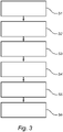
- a step S3 the connecting and disconnecting of the at least two energy storage devices are carried out alternatingly. This may be performed by means of the switching arrangement 115 as described with reference to Fig. 2 .
- step S4 the energy storage device which has been disconnected the longest time is connected for acting as buffer as previously described.
- step S4 may be combined with the step S3.
- step S5 which may be combined with the steps S3 and/or S4, the energy storage devices in the energy storage system are cycled in such a way that over time, each energy storage device is connected for transferring electrical energy from the energy source to the load roughly the same amount of time.
- step S4 may be omitted, as sometimes another energy storage device than the one being disconnected the longest time, may be connected.
- each energy storage device will be connected roughly the same time.
- step S6 which may carried out in parallel to any one of steps S2, S3, S4 and S5, which energy storage device that was previously connected for transferring electrical energy from the energy source to the load is remembered, and upon a subsequent step of electrically powering the load via the electrical energy storage system (step S2), another energy storage device for transferring electrical energy from the energy source to the load than the energy storage device previously used, is connected.
- This information is preferably stored in a physical memory.
- the memory, and step of memorizing which of the energy storage that was previously connected may be utilized also for the cycling of the energy storage devices in step S5. In such case, the time which each of the energy storage devices has been connected may be stored in the memory.
- any energy storage device(s) which is disconnected is primary disconnected from electrically powering the load, but may be connected to the electrical energy source for e.g. charging.
- any energy storage device(s) which is disconnected is disconnected from the electrical energy source.
- the power conditioning arrangement 110 of Fig. 2 may be implemented as the power conditioning arrangement 10 in vehicle 1 of Fig. 1 .
- the switching arrangement 115 may be implemented as the switching arrangement 15 in vehicle 1 of Fig. 1 , and may comprise a control unit, or be at least partly comprised in a control unit, such as a central control unit.
- the switching arrangement, or any related control unit may comprise a computer program comprising program code means for performing at least some of the method described with reference to Fig. 3
- Fig. 4 is schematic flow-chart describing an example operation sequence 200 with various possibilities of the energy storage system 30, 130 of Fig. 1 and Fig. 2 , e.g. using the power conditioning arrangement 110 and switching arrangement 115 of Fig. 2 , or a control unit as described above.
- a load such as an auxiliary load 40, 140 of Figs. 1 and 2
- the load is electrically powered 211 by at least one connected electrical energy source via the electrical energy storage system as described with reference to step S2 and Fig. 3 .
- the sequence 200 continues to stop or going to sleep 213.
- the load is electrically powered 211, the energy storage device that was connected for powering 211 the load is remembered (step S6 of Fig. 3 ), before stopping or going to sleep 213.
- Step S2 of Fig. 3 another energy storage device for transferring electrical energy from the electrical energy source to the load than the energy storage device previously used in 211, is connected.
- the cycling and alternating connection/disconnection as described with reference to steps S3, S4 and S5 of Fig. 3 may be achieved.
Landscapes
- Engineering & Computer Science (AREA)
- Power Engineering (AREA)
- Transportation (AREA)
- Mechanical Engineering (AREA)
- Life Sciences & Earth Sciences (AREA)
- Sustainable Development (AREA)
- Sustainable Energy (AREA)
- Charge And Discharge Circuits For Batteries Or The Like (AREA)
Abstract
Description
- The present invention relates to a method for reducing wear of an energy storage device in an energy storage system. The invention further relates to a switching arrangement, a power conditioning arrangement, and to an electric vehicle.
- A vehicle typically comprises an engine or machine for propelling the vehicle. The engine may be powered by various means, such as e.g. by a liquid or gaseous fuel in an internal combustion engine, or by electric power to an electric machine. Moreover, hybrid solutions exist in which e.g. the vehicle is propelled both by an internal combustion engine and an electric machine. In either way, an energy storage device is used to store the energy needed in order to propel the vehicle. Energy storage devices may further be used to power auxiliary loads in the vehicle.
- For many vehicle, the energy storage devices are comprised in an energy storage system, wherein the energy storage system is configured to power and engine or machine for propelling the vehicle, as well as an auxiliary load. For example, for an electric vehicle the energy storage devices are typically batteries, which are configured to operate the electric machine as well as electrically driven auxiliary equipment. The batteries are periodically in need of charging, and is then electrically connected to an electrical energy source. One common solution to charge the batteries is by a plug connected to the electrical energy source, e.g. a power source such as a power grid, by an electrical wire or cable. Typically, the vehicle is parked in a parking/charging spot providing such charging means, and the driver or other person manually plug the charging means into a socket of the vehicle, the socket being in electrical communication with the energy storage system and the batteries enabling charging of the same. Another solution to charge the battery is by a wireless charging system utilizing a power emitting coil and a power receiving coil configured to receive emitted electromagnetic radiation from the power emitting coil.
- During charging, or whenever the vehicle is electrically connected to an electrical energy source, an auxiliary load of the vehicle may be in need of powering. The auxiliary load may then be directly connected to the electrical energy source and operated by power from e.g. the power grid. However, when powering the auxiliary load in such a way, the system is not particularly robust to load changes.
- It is an object of the present disclosure to at least to some extent alleviate the shortcomings discussed above in relation to known energy storage systems, and to improve the operation of the energy storage devices.
- According to at least a first aspect of the present invention, a method for reducing wear of an energy storage device in an energy storage system connected to a load, the energy storage system comprising at least two energy storage devices, is provided. The method comprising:
- connecting the energy storage system to an electrical energy source,
- electrically powering the load via the energy storage system by connecting at least one of the energy storage devices to transfer electrical energy from the electrical energy source to the load, and disconnecting at least one other energy storage device to not transfer any electrical energy from the electrical energy source to the load.
- Hereby, at least one energy storage device is not active during powering of the load, and is thus not subject to any wear, while the energy storage system provides stable conditions for powering the load as at least one of the energy storage devices is used as buffer or load buffer in the system. Thus, the wear of the energy storage device which is not active during powering of the load, is reduced. In other words, one, or at least one, energy storage device is connected or is active in powering the load, and one energy storage device is disconnected or inactive in powering the load, wherein the wear of the latter may be reduced. Stated differently: the electrical energy source is electrically powering the load via the energy storage system in such a way that at least one energy storage device is active, and at least one energy storage device is inactive. This provides for a robust system with regards to load changes, with a minimized wear of the energy storage devices. The wear which is reduced may e.g. be contactor wear.
- It should be understood that at least one energy storage device which is active in powering the load, is used to provide an improved stability in the energy storage system (i.e. to function as a type of buffer or load buffer).
- According to at least one example embodiment, the energy storage system comprises an energy source interface, which energy source interface is connectable to the electrical energy source and each one of the energy storage devices. Thus, during use, the energy source interface is active in connecting the electrical energy source with the energy storage devices (whichever is active and/or is charging). Additionality, or alternatively, the energy storage system comprises a load interface, which load interface is connectable to the load and each one of the energy storage devices. Thus, during use, the load interface is active in connecting the energy storage devices (whichever is active) with the load.
- According to at least one example embodiment, the method comprises: alternately connecting and disconnecting the at least two energy storage devices.
- Hereby, at least one of the energy storage devices will not be active, and thus not subject to any wear. That is, connecting at least a first energy storage device to transfer electrical energy from the energy source to the load, and disconnecting at least a second energy storage device to not transfer electrical energy from the energy source to the load, and subsequently alternating the connection/disconnection such that the first energy storage device is disconnected and the second energy storage device is connected. The step of alternately connecting and disconnecting the at least two energy storage devices may be performed during the step of electrically powering the load, or between two such steps of electrically powering the load.
- According to at least one example embodiment, the energy storage system comprises a plurality of energy storage devices, the plurality being more than two, and the method further comprises: connecting the energy storage device which has been disconnected the longest time.
- Hereby, the overall wear of the energy storage devices can be reduced in an effective manner. The wear may be related to the number of a times an energy storage device is connected, and it is thus efficient to ensure that each energy storage device is connected/disconnected the same number of times. For example, in an embodiment in which the energy storage system comprises three energy storage devices, at a first step of electrically powering the load, a first energy storage device is connected (i.e. is active) while a second and third energy storage devices are disconnected (i.e. are inactive); at a subsequent second step of electrically powering the load, the second energy storage device is connected (i.e. is active) while the first and third energy storage devices are disconnected (i.e. are inactive); at a subsequent third step of electrically powering the load, the third energy storage device is connected (i.e. is active) while the first and second energy storage devices are disconnected (i.e. are inactive); at a subsequent fourth step of electrically powering the load, the first energy storage device is again connected (i.e. is active) while the second and third energy storage devices are disconnected (i.e. are inactive); and so on. The term "connecting the energy storage device which has been disconnected the longest time" may alternatively be phrased as "connecting the energy storage device which was connected the longest time ago". Stated differently, for the plurality of energy storage devices, the method comprises subsequently connecting and disconnecting the energy storage devices according to a scheme in which the energy storage that was first connected, is reconnected once the all of the energy storage devices have been connected one time.
- According to at least one example embodiment, the method comprises: cycling the energy storage devices in the energy storage system in such a way that over time, each energy storage device is connected for transferring electrical energy from the electrical energy source to the load roughly the same amount of time.
- Hereby, the overall wear of the energy storage devices can be reduced in an effective manner. For a specific or individual energy storage device, the wear may be related to the elapsed time which said energy storage device has been connected, and it is thus efficient to ensure that each energy storage device is connected/disconnected the same amount of time. It should be understood that the energy storage devices need not to be connected exactly the same amount of time, but roughly the same amount of time may. For example, over time, e.g. 10 days, or 30 days, or 300 days, no energy storage device has been connected a total time of more than 10 %, or more than 5 % compared to any other energy storage device in the energy storage system. Thus, over time, the above cycling and alternately connecting and disconnecting of the energy storage device, the energy storage devices may be connected the same number of times, as well as roughly the same amount of time. It should be noted that by using such cycling of the energy storage devices, it does not matter if an individual energy storage device is connected in two subsequent steps of electrically powering the load (i.e. is connected once, and directly thereafter re-connected), or if a certain energy storage device for some reason is temporarily unavailable and not included in the alternatively connecting and disconnecting activities, as over time, such connection inequalities may be evened out, with the result that each energy storage device is connected roughly the same amount of time.
- According to at least one example embodiment, the method comprises: remembering which energy storage device that was previously connected for transferring electrical energy from the electrical energy source to the load, upon a subsequent step of electrically powering the load via the electrical energy storage system, connecting another energy storage device for transferring electrical energy from the electrical energy source to the load than the energy storage device previously used.
- Hereby, an easy implemented but yet effective means for ensuring that different energy storage devices are connected every time is provided. It should be noted that the step of remembering may be implemented in the previously mentioned cycling of the energy storage devices (i.e. regardless if the different energy storage devices are connected every time or not).
- According to at least one example embodiment, during the step of electrically powering the load, only one energy storage device of the energy storage system is connected for transferring electrical energy from the electrical energy source to the load, and any other energy storage devices of the energy storage system is disconnected and is not transferring any electrical energy from the electrical energy source to the load.
- Hereby, the overall wear of the energy storage devices can be reduced in an effective manner. By only having one energy storage device connected, the previously mentioned buffer or load buffer is provided, while the wear is minimized or reduced. For example, in the above mentioned example embodiment with three energy storage devices, while one of the first, second and third energy storage devices is connected, the other two are disconnected.
- According to at least one example embodiment, the at least one energy storage device connected for transferring electrical energy from the electrical energy source to the load is not charging.
- Thus, such energy storage device may be considered at rest. However, according to at least one alternative example embodiment, at least one energy storage device connected for transferring electrical energy from the electrical energy source to the load is charging.
- According to at least one example embodiment, the at least one energy storage device disconnected to not transfer any electrical energy from the electrical energy source to the load is not charging.
- Thus, such energy storage device may be considered at rest, and is thus disconnected from both the electrical energy source and the load. However, according to at least one alternative example embodiment, at least one energy storage device disconnected to not transfer any electrical energy from the electrical energy source to the load is charging.
- Thus, an energy storage device which is not used as buffer or load buffer, may be charged. This provides an efficient use of the downtime of the energy storage devices.
- According to at least a second aspect of the invention, a switching arrangement for reducing wear of an energy storage device in an energy storage system connectable to an electrical energy source and to a load, the energy storage system comprising at least two energy storage devices, is provided. The switching arrangement is configured to electrically connect and disconnect each of the energy storage devices to the electrical energy source and/or the load, wherein the switching arrangement is configured to electrically power the load via the energy storage system in such a way that at least one energy storage device is connected for transferring electrical energy from the electrical energy source to the load, and at least one other energy storage device is disconnected and is not transferring any electrical energy.
- Effects and features of the second aspect of the invention are largely analogous to those described above in connection with the first aspect of the invention. Embodiments mentioned in relation to the first aspect of the invention are largely compatible with the second aspect of the invention, of which some are exemplified below.
- That is, the switching arrangement is configured to perform the steps of the method of the first aspect of the invention by connecting at least one of the energy storage devices to transfer electrical energy from the energy source to the load (i.e. that energy storage device being active), and disconnecting at least one other energy storage device to not transfer any electrical energy from the energy source to the load (i.e. that energy storage device being not active or inactive). Hereby, at least one energy storage device is not active during powering of the load, and is thus not subject to any wear.
- According to at least one example embodiment, the switching arrangement is configured to alternately connect and disconnect the at least two energy storage devices. The switching arrangement may e.g. comprise at least one contactor for each energy storage device.
- Hereby, an easy implemented but yet effective means for ensuring the function to alternately connecting and disconnecting the at least two energy storage devices, thus reducing the overall wear of the energy storage device, is provided.
- According to at least one example embodiment, the energy storage system comprises a plurality of energy storage devices, the plurality being more than two, and the switching arrangement is configured to connect the energy storage device which has been disconnected the longest time.
- Hereby, an easy implemented but yet effective means for reducing the overall wear of the energy storage devices in an effective manner is provided.
- According to at least one example embodiment, the switching arrangement is configured to cycle the energy storage devices in the energy storage system in such a way that over time, each energy storage device is connected for transferring electrical energy from the electrical energy source to the load roughly the same amount of time.
- Hereby, an easy implemented but yet effective means for providing the function of cycling the energy storage devices, thus reducing the overall wear of the energy storage devices in an effective manner is provided.
- According to at least one example embodiment, the switching arrangement is configured to remember which energy storage device that was previously connected for transferring electrical energy from the energy source to the load, and upon a subsequent action of electrically powering the load via the electrical energy storage system, to connect another energy storage device to transfer electrical energy from the energy source to the load than the energy storage device previously used.
- The switching arrangement may e.g. comprise a physical memory, or be communicatively connected to such physical memory. Hereby, an easy implemented but yet effective means for reducing the overall wear of the energy storage devices in an effective manner is provided.
- According to at least one example embodiment, the switching arrangement is configured to enable only one energy storage device of the energy storage system to be connected for transferring electrical energy from the electrical energy source to the load, and any other energy storage devices of the energy storage system to be disconnected and thus not transferring any electrical energy from the electrical energy source to the load.
- For such purpose, or function, the switching arrangement may e.g. be equipped with a processing unit, processing information concerning which energy storage device to connect, and which to disconnect (e.g. provided by a physical memory). Hereby, the overall wear of the energy storage devices can be reduced in an effective manner.
- According to at least a third aspect of the present invention, a power conditioning arrangement is provided. The power conditioning arrangement comprises:
- an energy storage system connectable to an electrical energy source, and to a load, the energy storage system comprising at least two energy storage devices, and
- a switching arrangement according to the first aspect of the invention.
- Effects and features of the third aspect of the invention are largely analogous to those described above in connection with the first and second aspects of the invention. Embodiments mentioned in relation to the first and second aspect of the invention, in particular those of the switching arrangement and corresponding activities, are largely compatible with the third aspect of the invention, of which some are exemplified below.
- According to at least one example embodiment, the energy storage system comprises a plurality of energy storage devices, the plurality being more than two. Thus, the energy storage system may comprise at least three energy storage devices.
- According to at least one example embodiment, the energy storage system comprises an energy source interface, which energy source interface is connectable to the electrical energy source and each one of the energy storage devices. Thus, during use, the energy source interface is active in connecting the electrical energy source with the energy storage devices (whichever is active and/or is charging). Additionality, or alternatively, the energy storage system comprises a load interface, which load interface is connectable to the load and each one of the energy storage devices. Thus, during use, the load interface is active in connecting the energy storage devices (whichever is active) with the load.
- According to at least a fourth aspect of the present invention, an electric vehicle is provided. The electric vehicle comprises a switching arrangement according the second aspect of the invention, or a power conditioning arrangement according to the second aspect of the invention.
- According to at least a fifth aspect of the present invention, a computer program is provided. The computer program comprising program code means for performing the method of the first aspect of the invention, when the program is run on a computer.
- Such computer program may e.g. be implemented in an ECU of the vehicle, or e.g. be comprised in a control unit of the switching arrangement.
- According to at least a sixth aspect of the present invention, a computer readable medium carrying a computer program comprising program code means for performing the method of the first aspect of the invention, when the program product is run on a computer, is provided.
- According to at least one example embodiment, applicable to any one of the first to sixth aspects of the invention, the energy storage devices are batteries, e.g. batteries adapted for a vehicle, such as e.g. a heavy duty truck.
- Further advantages and features of the present disclosure are disclosed and discussed in the following description and the accompanying drawings.
- With reference to the appended drawings, below follows a more detailed description of embodiments of the invention cited as examples.
- In the drawings:
-
Fig. 1 is a side schematic view of a vehicle in accordance with an example embodiment of the invention; -
Fig. 2 is a schematic view of a power conditioning arrangement comprising an energy storage system and a switching arrangement in accordance with an example embodiment of the invention; -
Fig. 3 is a flowchart illustrating the steps of a method in accordance with example embodiments of the invention; and -
Fig. 4 is yet another flowchart illustrating the steps of a method in accordance with example embodiments of the invention. - With reference to
Fig. 1 , avehicle 1, here embodied as aheavy duty truck 1, is disclosed for which a method, switchingarrangement 15, and/or apower conditioning arrangement 10 of a kind disclosed in the present invention is advantageous. However, the method, switchingarrangement 15 orpower conditioning arrangement 10 may as well be implemented in other types of vehicles, such as in busses, light-weight trucks, passenger cars, marine applications etc. Thevehicle 1 is an electric vehicle, such as a full electric vehicle or a hybrid, comprising at least oneelectric machine 20, anenergy storage system 30 comprising threeenergy storage devices energy storage system 30 being arranged and configured to power theelectric machine 20. Moreover, thevehicle 1 comprises anauxiliary load 40 arranged and configured for being powered by theenergy storage system 30, theauxiliary load 40 being e.g. a heater. Thus, theenergy storage system 30 is arranged and configured to supply at least twodifferent loads electric machine 20, and the second load being theauxiliary load 40. Thevehicle 1 typically further comprises other parts of the powertrain such as transmission, drive shafts and wheels (not shown in detail). - As seen in
Fig. 1 , theenergy storage system 30 is connected to anelectrical energy source 80 via an energy transfer means 90, typically a cable for transferring electrical energy to the threeenergy storage devices energy storage devices auxiliary load 40, may be powered directly via theelectrical energy source 80. In this case, the electric energy is preferably transferred via at least one of theenergy storage devices arrangement 15, e.g. by a functionality comprised in a control unit of the switchingarrangement 15, as will be described in the following. -
Fig. 2 is a schematic view of apower conditioning arrangement 110 comprising anenergy storage system 130 and aswitching arrangement 115. Theenergy storage system 130 is connected to two loads being e.g. anelectric machine 120 and anauxiliary load 140 arranged and configured for being powered by theenergy storage system 130, and connected to anelectrical energy source 180 supplying electrical energy to theenergy storage system 130. Moreover, theenergy storage system 130 comprises threeenergy storage devices energy source interface 134 providing an interface of the threeenergy storage devices electrical energy source 180, and aload interface 136 providing an interface of the threeenergy storage devices loads energy storage devices first contactor energy source interface 134 and theelectrical energy source 180, and a respectivesecond contactor load interface 136 and theloads contactors Fig. 2 , and may according to at least one example embodiment form for theenergy source interface 134, and theload interface 136, respectively. In other words, thefirst contactors second contactors contactors - The switching
arrangement 115 comprises acontrol unit 116, and is arranged and configured to control at least a part of the operation of theenergy storage system 130, and is inFig. 2 schematically illustrated to be connected to theenergy source interface 134 and theload interface 136. Hereby, thepower conditioning arrangement 110 may e.g. be configured to control charging of any one of theenergy storage devices loads power conditioning arrangement 110 is further configured to enable powering of any one of the twoloads electrical energy source 180, utilizing at least one of theenergy storage devices arrangement 115 is configured to electrically connect and disconnect each one of theenergy storage devices electrical energy source 180, inFig. 2 via theenergy source interface 134 and thefirst contactors energy storage devices loads Fig. 2 via theload interface 136 and thesecond contactors arrangement 115 is configured to electrically power any one of the twoloads energy storage system 130 in such a way that at least oneenergy storage device electrical energy source 180 to the particular load(s) 120, 140, and at least one otherenergy storage device energy storage device 131 is connected to theelectrical energy source 180 via theenergy source interface 134 and thefirst contactor 131A, and is connected to the particular load(s) 120, 140, e.g. theauxiliary load 140, via theload interface 136 and thesecond contactor 131B. Furthermore, second and thirdenergy storage devices electrical energy source 180 and/or the twoloads first contactors second contactors electrical energy source 180 to any one of the twoloads - Preferably, the switching
arrangement 115 is configured to alternately connect and disconnect theenergy storage devices energy storage system 130. Hereby, the at least oneenergy storage device loads electrical energy source 180. Thus, the switchingarrangement 115 may cycle theenergy storage devices energy storage system 130 in such a way that over time, eachenergy storage device energy source 180 to the load(s) 120, 140 roughly the same amount of time. Furthermore, the switchingarrangement 115 may be configured to connect theenergy storage device arrangement 115 is typically configured to remember which one of theenergy storage devices electrical energy source 180 to the load(s) 120, 140, and upon a subsequent action of electrically powering the load(s) 120, 140 via theenergy storage system 130, to connect another one of theenergy storage devices electrical energy source 180 to the load(s) 120, 140 than theenergy storage device energy storage devices energy storage device 131 of theenergy storage system 130 is connected at a time for transferring electrical energy from theelectrical energy source 180 to the load(s) 120, 140, and any otherenergy storage devices energy storage system 130 is disconnected and thus not transferring any electrical energy from theelectrical energy source 180 to the load(s) 120, 140, as the buffer of only one of theenergy storage devices - The operation of the
energy storage system Fig. 1 andFig. 2 will now be described in more general terms with additional reference toFigs. 3 and4 . Theenergy storage system energy storage devices Fig. 1 andFig. 2 (electric machine auxiliary load 40, 140). - In a step S1, the energy storage system is connected to an electrical energy source. The connection is preferably established by an electrical cable, but may as well be established by a wireless connection, such as e.g. inductive transfer of electrical energy. By stating that the energy storage system is connected to the electrical energy source, at least one of the energy storage devices is connected to the electrical energy source.
- In a step S2, the load is electrically powered by the connected electrical energy source via the electrical energy storage system by connecting at least one of the energy storage devices. Hereby electrical energy is transferred from the electrical energy source to the load, suing the at least one energy storage device as buffer. Moreover, in step S2, at least one other energy storage device is disconnected to not transfer any electrical energy from the electrical energy source to the load. The disconnection of at least one other energy storage device may be passive (i.e. if the particular energy storage device is disconnected by default, it is simply not connected as the load is electrically powered, or if it is connected by default, it is disconnected to disable the functionality of transferring electrical energy therethrough). The connection of the at least one of the energy storage devices may be carried out prior to, simultaneously, or subsequent to the disconnection of at least one other energy storage device. In order to minimize the wear of the energy storage devices, preferably only one energy storage device of the energy storage system is connected for transferring electrical energy from the energy source to the load, and any other energy storage devices of the energy storage system is disconnected and is not transferring any electrical energy from the energy source to the load.
- In a step S3, the connecting and disconnecting of the at least two energy storage devices are carried out alternatingly. This may be performed by means of the
switching arrangement 115 as described with reference toFig. 2 . - In a step S4, the energy storage device which has been disconnected the longest time is connected for acting as buffer as previously described. Thus, step S4 may be combined with the step S3.
- In a step S5, which may be combined with the steps S3 and/or S4, the energy storage devices in the energy storage system are cycled in such a way that over time, each energy storage device is connected for transferring electrical energy from the energy source to the load roughly the same amount of time. It should however be noted, that when utilizing the cycling of the energy storage devices in step S5, step S4 may be omitted, as sometimes another energy storage device than the one being disconnected the longest time, may be connected. However, over time, and by utilizing the cycling, each energy storage device will be connected roughly the same time.
- In a step S6, which may carried out in parallel to any one of steps S2, S3, S4 and S5, which energy storage device that was previously connected for transferring electrical energy from the energy source to the load is remembered, and upon a subsequent step of electrically powering the load via the electrical energy storage system (step S2), another energy storage device for transferring electrical energy from the energy source to the load than the energy storage device previously used, is connected. This information is preferably stored in a physical memory. As mentioned previously, the memory, and step of memorizing which of the energy storage that was previously connected, may be utilized also for the cycling of the energy storage devices in step S5. In such case, the time which each of the energy storage devices has been connected may be stored in the memory.
- It should be understood that any energy storage device(s) which is disconnected, is primary disconnected from electrically powering the load, but may be connected to the electrical energy source for e.g. charging. However, according to at least one example embodiment, any energy storage device(s) which is disconnected, is disconnected from the electrical energy source.
- It should be noted that the naming of the steps not necessarily, but might according to at least one example embodiment, relate to the order in which the steps are carried out. Thus, the order of the steps may be different than that explained here, and the switching arrangement of
Fig. 2 may be configured to carry out one or several of the steps. Moreover, one or more of the steps may be combined and carried out simultaneously. - It should be noted that the
power conditioning arrangement 110 ofFig. 2 may be implemented as thepower conditioning arrangement 10 invehicle 1 ofFig. 1 . Moreover, the switchingarrangement 115 may be implemented as the switchingarrangement 15 invehicle 1 ofFig. 1 , and may comprise a control unit, or be at least partly comprised in a control unit, such as a central control unit. The switching arrangement, or any related control unit, may comprise a computer program comprising program code means for performing at least some of the method described with reference toFig. 3 -
Fig. 4 is schematic flow-chart describing anexample operation sequence 200 with various possibilities of theenergy storage system Fig. 1 andFig. 2 , e.g. using thepower conditioning arrangement 110 and switchingarrangement 115 ofFig. 2 , or a control unit as described above. - Upon
initiation 201 of thesequence 200, the energy storage system is connected 203 to an electrical energy source as described with reference to step S1 andFig. 3 . Subsequently, it is determined if any one of the energy storage devices is in need of charging, symbolized byfirst determination box 205. If charging is needed (Y = Yes), the energy storage device(s) in need of charging is charged 207. If no charging is need (N = No) or when charging is completed, thesequence 200 continues to determine if a load, such as anauxiliary load Figs. 1 and2 , is in need of powering, e.g. in order to be charged, symbolized bysecond determination box 209. If powering of the load is needed (Y = Yes), the load is electrically powered 211 by at least one connected electrical energy source via the electrical energy storage system as described with reference to step S2 andFig. 3 . If no load is in need of powering (N = No), thesequence 200 continues to stop or going to sleep 213. In case the load is electrically powered 211, the energy storage device that was connected for powering 211 the load is remembered (step S6 ofFig. 3 ), before stopping or going to sleep 213. Thus, upon a subsequent step of powering the load via the electrical energy storage system (Step S2 ofFig. 3 ), another energy storage device for transferring electrical energy from the electrical energy source to the load than the energy storage device previously used in 211, is connected. Thus, the cycling and alternating connection/disconnection as described with reference to steps S3, S4 and S5 ofFig. 3 may be achieved. - It is to be understood that the present invention is not limited to the embodiments described above and illustrated in the drawings; rather, the skilled person will recognize that many changes and modifications may be made within the scope of the appended claims.
- Additionally, variations to the disclosed embodiments can be understood and effected by the skilled person in practicing the claimed inventive concept, from a study of the drawings, the disclosure, and the appended claims. In the claims, the word "comprising" does not exclude other elements or steps, and the indefinite article "a" or "an" does not exclude a plurality. The mere fact that certain measures are recited in mutually different dependent claims does not indicate that a combination of these measures cannot be used to advantage.
Claims (15)
- A method for reducing wear of an energy storage device in an energy storage system connected to a load, the energy storage system comprising at least two energy storage devices, the method comprising:- connecting (S1) the energy storage system to an electrical energy source,- electrically powering (S2) the load via the energy storage system by connecting at least one of the energy storage devices to transfer electrical energy from the electrical energy source to the load, and disconnecting at least one other energy storage device to not transfer any electrical energy from the electrical energy source to the load.
- The method according to claim 1, comprising:- alternately connecting and disconnecting (S3) the at least two energy storage devices.
- The method according to any one of the preceding claims, wherein the energy storage system comprises a plurality of energy storage devices, the plurality being more than two, and the method comprises:- connecting (S4) the energy storage device which has been disconnected the longest time.
- The method according to any one of the preceding claims, comprising:- cycling (S5) the energy storage devices in the energy storage system in such a way that over time, each energy storage device is connected for transferring electrical energy from the electrical energy source to the load roughly the same amount of time.
- The method according to any one of the preceding claims, comprising:- remembering (S6) which energy storage device that was previously connected for transferring electrical energy from the electrical energy source to the load, upon a subsequent step of electrically powering the load via the electrical energy storage system, connecting another energy storage device for transferring electrical energy from the electrical energy source to the load than the energy storage device previously used.
- The method according to any one of the preceding claims, wherein during electrically powering (S2) the load, only one energy storage device of the energy storage system is connected for transferring electrical energy from the electrical energy source to the load, and any other energy storage devices of the energy storage system is disconnected and is not transferring any electrical energy from the electrical energy source to the load.
- The method according to any one of the preceding claims, wherein the at least one energy storage device connected for transferring electrical energy from the electrical energy source to the load is not charging.
- A switching arrangement (15, 115) for reducing wear of an energy storage device (31, 32, 33, 131, 132, 133) in an energy storage system (30, 130) connectable to an electrical energy source (80, 180) and to a load (20, 40, 120, 140), the energy storage system comprising at least two energy storage devices, the switching arrangement (15, 115) being configured to electrically connect and disconnect each of the energy storage devices to the electrical energy source and/or the load, wherein the switching arrangement is configured to electrically power the load via the energy storage system in such a way that at least one energy storage device is connected for transferring electrical energy from the electrical energy source to the load, and at least one other energy storage device is disconnected and is not transferring any electrical energy.
- The switching arrangement according to claim 8, being configured to alternately connect and disconnect the at least two energy storage devices.
- The switching arrangement according to any one of claims 8-9, wherein, the energy storage system comprises a plurality of energy storage devices, the plurality being more than two, and wherein the switching arrangement is configured to connect the energy storage device which has been disconnected the longest time.
- The switching arrangement according to any one of claims 8-10, being configured to cycle the energy storage devices in the energy storage system in such a way that over time, each energy storage device is connected for transferring electrical energy from the electrical energy source to the load roughly the same amount of time.
- The switching arrangement according to any one of claims 8-11, being configured to remember which energy storage device that was previously connected for transferring electrical energy from the energy source to the load, and upon a subsequent action of electrically powering the load via the electrical energy storage system, to connect another energy storage device to transfer electrical energy from the energy source to the load than the energy storage device previously used.
- The switching arrangement according to any one of claims 8-12, being configured to enable only one energy storage device of the energy storage system to be connected for transferring electrical energy from the electrical energy source to the load, and any other energy storage devices of the energy storage system to be disconnected and thus not transferring any electrical energy from the electrical energy source to the load.
- A power conditioning arrangement (10, 110) comprising:- an energy storage system (30, 130) connectable to an electrical energy source (80, 180) and to a load (20, 40, 120, 140), the energy storage system comprising at least two energy storage devices, and- a switching arrangement (15, 115) according to any one of claims 8-13.
- An electric vehicle (1) comprising switching arrangement according to any one of claims 8-13, or a power conditioning arrangement according to claim 14.
Priority Applications (3)
| Application Number | Priority Date | Filing Date | Title |
|---|---|---|---|
| EP20202042.6A EP3984805B1 (en) | 2020-10-15 | 2020-10-15 | A method for reducing wear of an energy storage device |
| CN202111175971.6A CN114425948B (en) | 2020-10-15 | 2021-10-09 | Method for reducing wear of an energy storage device |
| US17/450,515 US12266952B2 (en) | 2020-10-15 | 2021-10-11 | Method for reducing wear of an energy storage device |
Applications Claiming Priority (1)
| Application Number | Priority Date | Filing Date | Title |
|---|---|---|---|
| EP20202042.6A EP3984805B1 (en) | 2020-10-15 | 2020-10-15 | A method for reducing wear of an energy storage device |
Publications (2)
| Publication Number | Publication Date |
|---|---|
| EP3984805A1 true EP3984805A1 (en) | 2022-04-20 |
| EP3984805B1 EP3984805B1 (en) | 2026-04-22 |
Family
ID=73020040
Family Applications (1)
| Application Number | Title | Priority Date | Filing Date |
|---|---|---|---|
| EP20202042.6A Active EP3984805B1 (en) | 2020-10-15 | 2020-10-15 | A method for reducing wear of an energy storage device |
Country Status (3)
| Country | Link |
|---|---|
| US (1) | US12266952B2 (en) |
| EP (1) | EP3984805B1 (en) |
| CN (1) | CN114425948B (en) |
Families Citing this family (1)
| Publication number | Priority date | Publication date | Assignee | Title |
|---|---|---|---|---|
| EP4375113A1 (en) | 2022-11-28 | 2024-05-29 | Volvo Truck Corporation | A method for operating a switching arrangement |
Citations (4)
| Publication number | Priority date | Publication date | Assignee | Title |
|---|---|---|---|---|
| US20030107352A1 (en) * | 2001-12-06 | 2003-06-12 | Downer Scott D. | Electrical motor power management system |
| EP2460254A2 (en) * | 2009-07-31 | 2012-06-06 | Thermo King Corporation | Bi-directional battery voltage converter |
| US20120326510A1 (en) * | 2011-06-24 | 2012-12-27 | Lawrence Sadler | Power Conditioning System |
| EP3110652A1 (en) * | 2014-02-24 | 2017-01-04 | Volvo Truck Corporation | Electrical storage system for a vehicle and method for controlling said system |
Family Cites Families (17)
| Publication number | Priority date | Publication date | Assignee | Title |
|---|---|---|---|---|
| DE3326729A1 (en) * | 1983-07-25 | 1985-02-07 | Siemens AG, 1000 Berlin und 8000 München | METHOD FOR OPERATING AN ELECTROCHEMICAL STORAGE |
| DE19625104A1 (en) * | 1996-06-24 | 1998-01-08 | Continental Ag | Power supply method for intrinsically safe systems, such as motor vehicle braking system |
| SE0402874L (en) * | 2004-11-25 | 2005-08-23 | Aros Electronics Ab | Energy distribution circuit in vehicles |
| WO2013016538A2 (en) * | 2011-07-26 | 2013-01-31 | Gogoro, Inc. | Thermal management of components in electric motor drive vehicles |
| WO2014196933A1 (en) * | 2013-06-06 | 2014-12-11 | Nanyang Technological University | Battery charging devices, battery charging methods, battery systems, and methods for controlling batteries |
| DE102014200336A1 (en) * | 2014-01-10 | 2015-07-16 | Robert Bosch Gmbh | Electrochemical storage composite |
| JP6353746B2 (en) * | 2014-08-26 | 2018-07-04 | 矢崎総業株式会社 | Vehicle power supply control system, wire harness, and vehicle power supply control device |
| TWI517521B (en) * | 2014-12-08 | 2016-01-11 | 財團法人工業技術研究院 | Programmable battery source architecture and method thereof |
| CN106143170B (en) * | 2015-03-31 | 2020-11-17 | 通用电气公司 | Energy storage system with range extender and energy management control method |
| DE102016200086A1 (en) * | 2016-01-07 | 2017-07-13 | Robert Bosch Gmbh | board network |
| US20170366019A1 (en) * | 2016-06-16 | 2017-12-21 | EcoReco Global Corporation | Battery Switching System and Method Thereof |
| EP3497776A4 (en) * | 2016-08-10 | 2020-02-05 | Briggs & Stratton Corporation | USER-SCALE POWER SUPPLY UNIT COMPRISING REMOVABLE BATTERIES |
| JP6358304B2 (en) * | 2016-09-30 | 2018-07-18 | 株式会社オートネットワーク技術研究所 | Vehicle power supply |
| EP3624301A1 (en) * | 2018-09-11 | 2020-03-18 | Embraer S.A. | Method and system for distributed electrical loads connected to shared power sources |
| US20210031645A1 (en) * | 2019-07-30 | 2021-02-04 | Goodwyn George Reeves | Vehicle Battery Pack and Battery Exchange System |
| SE544083C2 (en) * | 2019-11-11 | 2021-12-14 | Sem Ab | Battery assembly with controllable voltage and method related thereto |
| US11077767B2 (en) * | 2019-12-27 | 2021-08-03 | Lyft, Inc. | Vehicle battery integration systems and methods |
-
2020
- 2020-10-15 EP EP20202042.6A patent/EP3984805B1/en active Active
-
2021
- 2021-10-09 CN CN202111175971.6A patent/CN114425948B/en active Active
- 2021-10-11 US US17/450,515 patent/US12266952B2/en active Active
Patent Citations (4)
| Publication number | Priority date | Publication date | Assignee | Title |
|---|---|---|---|---|
| US20030107352A1 (en) * | 2001-12-06 | 2003-06-12 | Downer Scott D. | Electrical motor power management system |
| EP2460254A2 (en) * | 2009-07-31 | 2012-06-06 | Thermo King Corporation | Bi-directional battery voltage converter |
| US20120326510A1 (en) * | 2011-06-24 | 2012-12-27 | Lawrence Sadler | Power Conditioning System |
| EP3110652A1 (en) * | 2014-02-24 | 2017-01-04 | Volvo Truck Corporation | Electrical storage system for a vehicle and method for controlling said system |
Also Published As
| Publication number | Publication date |
|---|---|
| EP3984805B1 (en) | 2026-04-22 |
| US20220123561A1 (en) | 2022-04-21 |
| US12266952B2 (en) | 2025-04-01 |
| CN114425948B (en) | 2024-09-17 |
| CN114425948A (en) | 2022-05-03 |
Similar Documents
| Publication | Publication Date | Title |
|---|---|---|
| US8183821B2 (en) | Charging device for electric automobile | |
| US10800279B2 (en) | Portable charging system and charging method | |
| US10850725B2 (en) | Vehicles with modular parallel high voltage batteries | |
| CN104972886B (en) | Electric power system of hybrid vehicle | |
| US20160114692A1 (en) | Battery charging devices, battery charging methods, battery systems, and methods for controlling batteries | |
| US10093167B2 (en) | Electric or hybrid electric vehicle having multiple drive units arranged in separate parts of the vehicle | |
| US10259336B2 (en) | Charging a battery using interpack switch | |
| CN101357594B (en) | Electric traction system for a vehicle having a dual winding AC traction motor | |
| CN102421630B (en) | Power supply system and vehicle equipped with power supply system | |
| CN112753150A (en) | Vehicle with integrated charging system | |
| CN101420184A (en) | Double ended inverter system with an impedance source inverter subsystem | |
| CN104972885A (en) | Electrical Power System For Hybrid Vehicles | |
| CN108215878A (en) | For the vehicle charging system to electric vehicle direct current quick charge | |
| CN101357593A (en) | Charging energy sources with a rectifier using double-ended inverter system | |
| US11458849B2 (en) | Charging input selector systems for electrified vehicles | |
| CN109843626B (en) | Hybrid vehicle | |
| EP4204253A1 (en) | Electrical power circuit for charging an electric vehicle and having a dc/dc converter for supplying electricity to auxiliary devices | |
| CN104169152A (en) | Isolation contactor transition polarity control | |
| US12266952B2 (en) | Method for reducing wear of an energy storage device | |
| US11667213B2 (en) | Electromobility system for a vehicle | |
| EP2765670B1 (en) | Electric vehicle power supply system and method for controlling same | |
| US11831185B2 (en) | Method for operating a switching arrangement of an energy storage system | |
| US20250170902A1 (en) | Electrical traction system for an industrial electric vehicle, industrial electric vehicle, electrical power supply system and method of providing electrical energy to an industrial electric vehicle | |
| CN113135104B (en) | Method of charging electric vehicles | |
| US20220379739A1 (en) | High voltage traction system for a vehicle |
Legal Events
| Date | Code | Title | Description |
|---|---|---|---|
| PUAI | Public reference made under article 153(3) epc to a published international application that has entered the european phase |
Free format text: ORIGINAL CODE: 0009012 |
|
| STAA | Information on the status of an ep patent application or granted ep patent |
Free format text: STATUS: THE APPLICATION HAS BEEN PUBLISHED |
|
| AK | Designated contracting states |
Kind code of ref document: A1 Designated state(s): AL AT BE BG CH CY CZ DE DK EE ES FI FR GB GR HR HU IE IS IT LI LT LU LV MC MK MT NL NO PL PT RO RS SE SI SK SM TR |
|
| STAA | Information on the status of an ep patent application or granted ep patent |
Free format text: STATUS: REQUEST FOR EXAMINATION WAS MADE |
|
| 17P | Request for examination filed |
Effective date: 20221004 |
|
| RBV | Designated contracting states (corrected) |
Designated state(s): AL AT BE BG CH CY CZ DE DK EE ES FI FR GB GR HR HU IE IS IT LI LT LU LV MC MK MT NL NO PL PT RO RS SE SI SK SM TR |
|
| STAA | Information on the status of an ep patent application or granted ep patent |
Free format text: STATUS: EXAMINATION IS IN PROGRESS |
|
| 17Q | First examination report despatched |
Effective date: 20230215 |
|
| GRAP | Despatch of communication of intention to grant a patent |
Free format text: ORIGINAL CODE: EPIDOSNIGR1 |
|
| STAA | Information on the status of an ep patent application or granted ep patent |
Free format text: STATUS: GRANT OF PATENT IS INTENDED |
|
| INTG | Intention to grant announced |
Effective date: 20250721 |
|
| GRAJ | Information related to disapproval of communication of intention to grant by the applicant or resumption of examination proceedings by the epo deleted |
Free format text: ORIGINAL CODE: EPIDOSDIGR1 |
|
| STAA | Information on the status of an ep patent application or granted ep patent |
Free format text: STATUS: EXAMINATION IS IN PROGRESS |
|
| GRAP | Despatch of communication of intention to grant a patent |
Free format text: ORIGINAL CODE: EPIDOSNIGR1 |
|
| STAA | Information on the status of an ep patent application or granted ep patent |
Free format text: STATUS: GRANT OF PATENT IS INTENDED |
|
| INTC | Intention to grant announced (deleted) | ||
| INTG | Intention to grant announced |
Effective date: 20251117 |
|
| GRAS | Grant fee paid |
Free format text: ORIGINAL CODE: EPIDOSNIGR3 |
|
| GRAA | (expected) grant |
Free format text: ORIGINAL CODE: 0009210 |
|
| STAA | Information on the status of an ep patent application or granted ep patent |
Free format text: STATUS: THE PATENT HAS BEEN GRANTED |
|
| AK | Designated contracting states |
Kind code of ref document: B1 Designated state(s): AL AT BE BG CH CY CZ DE DK EE ES FI FR GB GR HR HU IE IS IT LI LT LU LV MC MK MT NL NO PL PT RO RS SE SI SK SM TR |
|
| REG | Reference to a national code |
Ref country code: CH Ref legal event code: F10 Free format text: ST27 STATUS EVENT CODE: U-0-0-F10-F00 (AS PROVIDED BY THE NATIONAL OFFICE) Effective date: 20260422 Ref country code: GB Ref legal event code: FG4D |
|
| REG | Reference to a national code |
Ref country code: DE Ref legal event code: R096 Ref document number: 602020070676 Country of ref document: DE |