EP3984804A1 - Projection switching device - Google Patents
Projection switching device Download PDFInfo
- Publication number
- EP3984804A1 EP3984804A1 EP21202888.0A EP21202888A EP3984804A1 EP 3984804 A1 EP3984804 A1 EP 3984804A1 EP 21202888 A EP21202888 A EP 21202888A EP 3984804 A1 EP3984804 A1 EP 3984804A1
- Authority
- EP
- European Patent Office
- Prior art keywords
- projection
- touch
- switching device
- symbol
- lower garnish
- Prior art date
- Legal status (The legal status is an assumption and is not a legal conclusion. Google has not performed a legal analysis and makes no representation as to the accuracy of the status listed.)
- Pending
Links
Images



Classifications
-
- B—PERFORMING OPERATIONS; TRANSPORTING
- B60—VEHICLES IN GENERAL
- B60K—ARRANGEMENT OR MOUNTING OF PROPULSION UNITS OR OF TRANSMISSIONS IN VEHICLES; ARRANGEMENT OR MOUNTING OF PLURAL DIVERSE PRIME-MOVERS IN VEHICLES; AUXILIARY DRIVES FOR VEHICLES; INSTRUMENTATION OR DASHBOARDS FOR VEHICLES; ARRANGEMENTS IN CONNECTION WITH COOLING, AIR INTAKE, GAS EXHAUST OR FUEL SUPPLY OF PROPULSION UNITS IN VEHICLES
- B60K35/00—Instruments specially adapted for vehicles; Arrangement of instruments in or on vehicles
-
- G—PHYSICS
- G06—COMPUTING OR CALCULATING; COUNTING
- G06F—ELECTRIC DIGITAL DATA PROCESSING
- G06F3/00—Input arrangements for transferring data to be processed into a form capable of being handled by the computer; Output arrangements for transferring data from processing unit to output unit, e.g. interface arrangements
- G06F3/01—Input arrangements or combined input and output arrangements for interaction between user and computer
- G06F3/03—Arrangements for converting the position or the displacement of a member into a coded form
- G06F3/041—Digitisers, e.g. for touch screens or touch pads, characterised by the transducing means
- G06F3/042—Digitisers, e.g. for touch screens or touch pads, characterised by the transducing means by opto-electronic means
-
- G—PHYSICS
- G06—COMPUTING OR CALCULATING; COUNTING
- G06F—ELECTRIC DIGITAL DATA PROCESSING
- G06F3/00—Input arrangements for transferring data to be processed into a form capable of being handled by the computer; Output arrangements for transferring data from processing unit to output unit, e.g. interface arrangements
- G06F3/01—Input arrangements or combined input and output arrangements for interaction between user and computer
- G06F3/03—Arrangements for converting the position or the displacement of a member into a coded form
- G06F3/041—Digitisers, e.g. for touch screens or touch pads, characterised by the transducing means
-
- B—PERFORMING OPERATIONS; TRANSPORTING
- B60—VEHICLES IN GENERAL
- B60K—ARRANGEMENT OR MOUNTING OF PROPULSION UNITS OR OF TRANSMISSIONS IN VEHICLES; ARRANGEMENT OR MOUNTING OF PLURAL DIVERSE PRIME-MOVERS IN VEHICLES; AUXILIARY DRIVES FOR VEHICLES; INSTRUMENTATION OR DASHBOARDS FOR VEHICLES; ARRANGEMENTS IN CONNECTION WITH COOLING, AIR INTAKE, GAS EXHAUST OR FUEL SUPPLY OF PROPULSION UNITS IN VEHICLES
- B60K35/00—Instruments specially adapted for vehicles; Arrangement of instruments in or on vehicles
- B60K35/10—Input arrangements, i.e. from user to vehicle, associated with vehicle functions or specially adapted therefor
-
- B—PERFORMING OPERATIONS; TRANSPORTING
- B60—VEHICLES IN GENERAL
- B60K—ARRANGEMENT OR MOUNTING OF PROPULSION UNITS OR OF TRANSMISSIONS IN VEHICLES; ARRANGEMENT OR MOUNTING OF PLURAL DIVERSE PRIME-MOVERS IN VEHICLES; AUXILIARY DRIVES FOR VEHICLES; INSTRUMENTATION OR DASHBOARDS FOR VEHICLES; ARRANGEMENTS IN CONNECTION WITH COOLING, AIR INTAKE, GAS EXHAUST OR FUEL SUPPLY OF PROPULSION UNITS IN VEHICLES
- B60K35/00—Instruments specially adapted for vehicles; Arrangement of instruments in or on vehicles
- B60K35/20—Output arrangements, i.e. from vehicle to user, associated with vehicle functions or specially adapted therefor
- B60K35/21—Output arrangements, i.e. from vehicle to user, associated with vehicle functions or specially adapted therefor using visual output, e.g. blinking lights or matrix displays
-
- B—PERFORMING OPERATIONS; TRANSPORTING
- B60—VEHICLES IN GENERAL
- B60K—ARRANGEMENT OR MOUNTING OF PROPULSION UNITS OR OF TRANSMISSIONS IN VEHICLES; ARRANGEMENT OR MOUNTING OF PLURAL DIVERSE PRIME-MOVERS IN VEHICLES; AUXILIARY DRIVES FOR VEHICLES; INSTRUMENTATION OR DASHBOARDS FOR VEHICLES; ARRANGEMENTS IN CONNECTION WITH COOLING, AIR INTAKE, GAS EXHAUST OR FUEL SUPPLY OF PROPULSION UNITS IN VEHICLES
- B60K35/00—Instruments specially adapted for vehicles; Arrangement of instruments in or on vehicles
- B60K35/20—Output arrangements, i.e. from vehicle to user, associated with vehicle functions or specially adapted therefor
- B60K35/21—Output arrangements, i.e. from vehicle to user, associated with vehicle functions or specially adapted therefor using visual output, e.g. blinking lights or matrix displays
- B60K35/22—Display screens
-
- B—PERFORMING OPERATIONS; TRANSPORTING
- B60—VEHICLES IN GENERAL
- B60K—ARRANGEMENT OR MOUNTING OF PROPULSION UNITS OR OF TRANSMISSIONS IN VEHICLES; ARRANGEMENT OR MOUNTING OF PLURAL DIVERSE PRIME-MOVERS IN VEHICLES; AUXILIARY DRIVES FOR VEHICLES; INSTRUMENTATION OR DASHBOARDS FOR VEHICLES; ARRANGEMENTS IN CONNECTION WITH COOLING, AIR INTAKE, GAS EXHAUST OR FUEL SUPPLY OF PROPULSION UNITS IN VEHICLES
- B60K35/00—Instruments specially adapted for vehicles; Arrangement of instruments in or on vehicles
- B60K35/20—Output arrangements, i.e. from vehicle to user, associated with vehicle functions or specially adapted therefor
- B60K35/28—Output arrangements, i.e. from vehicle to user, associated with vehicle functions or specially adapted therefor characterised by the type of the output information, e.g. video entertainment or vehicle dynamics information; characterised by the purpose of the output information, e.g. for attracting the attention of the driver
-
- B—PERFORMING OPERATIONS; TRANSPORTING
- B60—VEHICLES IN GENERAL
- B60K—ARRANGEMENT OR MOUNTING OF PROPULSION UNITS OR OF TRANSMISSIONS IN VEHICLES; ARRANGEMENT OR MOUNTING OF PLURAL DIVERSE PRIME-MOVERS IN VEHICLES; AUXILIARY DRIVES FOR VEHICLES; INSTRUMENTATION OR DASHBOARDS FOR VEHICLES; ARRANGEMENTS IN CONNECTION WITH COOLING, AIR INTAKE, GAS EXHAUST OR FUEL SUPPLY OF PROPULSION UNITS IN VEHICLES
- B60K35/00—Instruments specially adapted for vehicles; Arrangement of instruments in or on vehicles
- B60K35/50—Instruments characterised by their means of attachment to or integration in the vehicle
-
- B—PERFORMING OPERATIONS; TRANSPORTING
- B60—VEHICLES IN GENERAL
- B60K—ARRANGEMENT OR MOUNTING OF PROPULSION UNITS OR OF TRANSMISSIONS IN VEHICLES; ARRANGEMENT OR MOUNTING OF PLURAL DIVERSE PRIME-MOVERS IN VEHICLES; AUXILIARY DRIVES FOR VEHICLES; INSTRUMENTATION OR DASHBOARDS FOR VEHICLES; ARRANGEMENTS IN CONNECTION WITH COOLING, AIR INTAKE, GAS EXHAUST OR FUEL SUPPLY OF PROPULSION UNITS IN VEHICLES
- B60K35/00—Instruments specially adapted for vehicles; Arrangement of instruments in or on vehicles
- B60K35/60—Instruments characterised by their location or relative disposition in or on vehicles
-
- B—PERFORMING OPERATIONS; TRANSPORTING
- B60—VEHICLES IN GENERAL
- B60K—ARRANGEMENT OR MOUNTING OF PROPULSION UNITS OR OF TRANSMISSIONS IN VEHICLES; ARRANGEMENT OR MOUNTING OF PLURAL DIVERSE PRIME-MOVERS IN VEHICLES; AUXILIARY DRIVES FOR VEHICLES; INSTRUMENTATION OR DASHBOARDS FOR VEHICLES; ARRANGEMENTS IN CONNECTION WITH COOLING, AIR INTAKE, GAS EXHAUST OR FUEL SUPPLY OF PROPULSION UNITS IN VEHICLES
- B60K35/00—Instruments specially adapted for vehicles; Arrangement of instruments in or on vehicles
- B60K35/65—Instruments specially adapted for specific vehicle types or users, e.g. for left- or right-hand drive
- B60K35/658—Instruments specially adapted for specific vehicle types or users, e.g. for left- or right-hand drive the instruments being ergonomically adjustable to the user
-
- B—PERFORMING OPERATIONS; TRANSPORTING
- B60—VEHICLES IN GENERAL
- B60K—ARRANGEMENT OR MOUNTING OF PROPULSION UNITS OR OF TRANSMISSIONS IN VEHICLES; ARRANGEMENT OR MOUNTING OF PLURAL DIVERSE PRIME-MOVERS IN VEHICLES; AUXILIARY DRIVES FOR VEHICLES; INSTRUMENTATION OR DASHBOARDS FOR VEHICLES; ARRANGEMENTS IN CONNECTION WITH COOLING, AIR INTAKE, GAS EXHAUST OR FUEL SUPPLY OF PROPULSION UNITS IN VEHICLES
- B60K35/00—Instruments specially adapted for vehicles; Arrangement of instruments in or on vehicles
- B60K35/80—Arrangements for controlling instruments
-
- B—PERFORMING OPERATIONS; TRANSPORTING
- B60—VEHICLES IN GENERAL
- B60K—ARRANGEMENT OR MOUNTING OF PROPULSION UNITS OR OF TRANSMISSIONS IN VEHICLES; ARRANGEMENT OR MOUNTING OF PLURAL DIVERSE PRIME-MOVERS IN VEHICLES; AUXILIARY DRIVES FOR VEHICLES; INSTRUMENTATION OR DASHBOARDS FOR VEHICLES; ARRANGEMENTS IN CONNECTION WITH COOLING, AIR INTAKE, GAS EXHAUST OR FUEL SUPPLY OF PROPULSION UNITS IN VEHICLES
- B60K35/00—Instruments specially adapted for vehicles; Arrangement of instruments in or on vehicles
- B60K35/80—Arrangements for controlling instruments
- B60K35/81—Arrangements for controlling instruments for controlling displays
-
- B—PERFORMING OPERATIONS; TRANSPORTING
- B60—VEHICLES IN GENERAL
- B60K—ARRANGEMENT OR MOUNTING OF PROPULSION UNITS OR OF TRANSMISSIONS IN VEHICLES; ARRANGEMENT OR MOUNTING OF PLURAL DIVERSE PRIME-MOVERS IN VEHICLES; AUXILIARY DRIVES FOR VEHICLES; INSTRUMENTATION OR DASHBOARDS FOR VEHICLES; ARRANGEMENTS IN CONNECTION WITH COOLING, AIR INTAKE, GAS EXHAUST OR FUEL SUPPLY OF PROPULSION UNITS IN VEHICLES
- B60K35/00—Instruments specially adapted for vehicles; Arrangement of instruments in or on vehicles
- B60K35/90—Calibration of instruments, e.g. setting initial or reference parameters; Testing of instruments, e.g. detecting malfunction
-
- B—PERFORMING OPERATIONS; TRANSPORTING
- B60—VEHICLES IN GENERAL
- B60R—VEHICLES, VEHICLE FITTINGS, OR VEHICLE PARTS, NOT OTHERWISE PROVIDED FOR
- B60R16/00—Electric or fluid circuits specially adapted for vehicles and not otherwise provided for; Arrangement of elements of electric or fluid circuits specially adapted for vehicles and not otherwise provided for
- B60R16/005—Electro-mechanical devices, e.g. switched
-
- B—PERFORMING OPERATIONS; TRANSPORTING
- B60—VEHICLES IN GENERAL
- B60R—VEHICLES, VEHICLE FITTINGS, OR VEHICLE PARTS, NOT OTHERWISE PROVIDED FOR
- B60R16/00—Electric or fluid circuits specially adapted for vehicles and not otherwise provided for; Arrangement of elements of electric or fluid circuits specially adapted for vehicles and not otherwise provided for
- B60R16/02—Electric or fluid circuits specially adapted for vehicles and not otherwise provided for; Arrangement of elements of electric or fluid circuits specially adapted for vehicles and not otherwise provided for electric constitutive elements
-
- G—PHYSICS
- G06—COMPUTING OR CALCULATING; COUNTING
- G06F—ELECTRIC DIGITAL DATA PROCESSING
- G06F3/00—Input arrangements for transferring data to be processed into a form capable of being handled by the computer; Output arrangements for transferring data from processing unit to output unit, e.g. interface arrangements
- G06F3/01—Input arrangements or combined input and output arrangements for interaction between user and computer
- G06F3/03—Arrangements for converting the position or the displacement of a member into a coded form
- G06F3/041—Digitisers, e.g. for touch screens or touch pads, characterised by the transducing means
- G06F3/0416—Control or interface arrangements specially adapted for digitisers
-
- G—PHYSICS
- G09—EDUCATION; CRYPTOGRAPHY; DISPLAY; ADVERTISING; SEALS
- G09F—DISPLAYING; ADVERTISING; SIGNS; LABELS OR NAME-PLATES; SEALS
- G09F13/00—Illuminated signs; Luminous advertising
- G09F13/20—Illuminated signs; Luminous advertising with luminescent surfaces or parts
- G09F13/22—Illuminated signs; Luminous advertising with luminescent surfaces or parts electroluminescent
-
- G—PHYSICS
- G09—EDUCATION; CRYPTOGRAPHY; DISPLAY; ADVERTISING; SEALS
- G09F—DISPLAYING; ADVERTISING; SIGNS; LABELS OR NAME-PLATES; SEALS
- G09F9/00—Indicating arrangements for variable information in which the information is built-up on a support by selection or combination of individual elements
- G09F9/40—Indicating arrangements for variable information in which the information is built-up on a support by selection or combination of individual elements in which the desired character is selected from a number of characters arranged one beside the other, e.g. on a common carrier plate
- G09F9/405—Indicating arrangements for variable information in which the information is built-up on a support by selection or combination of individual elements in which the desired character is selected from a number of characters arranged one beside the other, e.g. on a common carrier plate the selected character being projected on a common screen accommodating only one character at a time, to provide the same display position for all characters
-
- G—PHYSICS
- G09—EDUCATION; CRYPTOGRAPHY; DISPLAY; ADVERTISING; SEALS
- G09G—ARRANGEMENTS OR CIRCUITS FOR CONTROL OF INDICATING DEVICES USING STATIC MEANS TO PRESENT VARIABLE INFORMATION
- G09G3/00—Control arrangements or circuits, of interest only in connection with visual indicators other than cathode-ray tubes
- G09G3/001—Control arrangements or circuits, of interest only in connection with visual indicators other than cathode-ray tubes using specific devices not provided for in groups G09G3/02 - G09G3/36, e.g. using an intermediate record carrier such as a film slide; Projection systems; Display of non-alphanumerical information, solely or in combination with alphanumerical information, e.g. digital display on projected diapositive as background
-
- B—PERFORMING OPERATIONS; TRANSPORTING
- B60—VEHICLES IN GENERAL
- B60K—ARRANGEMENT OR MOUNTING OF PROPULSION UNITS OR OF TRANSMISSIONS IN VEHICLES; ARRANGEMENT OR MOUNTING OF PLURAL DIVERSE PRIME-MOVERS IN VEHICLES; AUXILIARY DRIVES FOR VEHICLES; INSTRUMENTATION OR DASHBOARDS FOR VEHICLES; ARRANGEMENTS IN CONNECTION WITH COOLING, AIR INTAKE, GAS EXHAUST OR FUEL SUPPLY OF PROPULSION UNITS IN VEHICLES
- B60K2360/00—Indexing scheme associated with groups B60K35/00 or B60K37/00 relating to details of instruments or dashboards
- B60K2360/143—Touch sensitive instrument input devices
-
- B—PERFORMING OPERATIONS; TRANSPORTING
- B60—VEHICLES IN GENERAL
- B60K—ARRANGEMENT OR MOUNTING OF PROPULSION UNITS OR OF TRANSMISSIONS IN VEHICLES; ARRANGEMENT OR MOUNTING OF PLURAL DIVERSE PRIME-MOVERS IN VEHICLES; AUXILIARY DRIVES FOR VEHICLES; INSTRUMENTATION OR DASHBOARDS FOR VEHICLES; ARRANGEMENTS IN CONNECTION WITH COOLING, AIR INTAKE, GAS EXHAUST OR FUEL SUPPLY OF PROPULSION UNITS IN VEHICLES
- B60K2360/00—Indexing scheme associated with groups B60K35/00 or B60K37/00 relating to details of instruments or dashboards
- B60K2360/143—Touch sensitive instrument input devices
- B60K2360/1434—Touch panels
-
- B—PERFORMING OPERATIONS; TRANSPORTING
- B60—VEHICLES IN GENERAL
- B60K—ARRANGEMENT OR MOUNTING OF PROPULSION UNITS OR OF TRANSMISSIONS IN VEHICLES; ARRANGEMENT OR MOUNTING OF PLURAL DIVERSE PRIME-MOVERS IN VEHICLES; AUXILIARY DRIVES FOR VEHICLES; INSTRUMENTATION OR DASHBOARDS FOR VEHICLES; ARRANGEMENTS IN CONNECTION WITH COOLING, AIR INTAKE, GAS EXHAUST OR FUEL SUPPLY OF PROPULSION UNITS IN VEHICLES
- B60K2360/00—Indexing scheme associated with groups B60K35/00 or B60K37/00 relating to details of instruments or dashboards
- B60K2360/143—Touch sensitive instrument input devices
- B60K2360/1438—Touch screens
-
- B—PERFORMING OPERATIONS; TRANSPORTING
- B60—VEHICLES IN GENERAL
- B60K—ARRANGEMENT OR MOUNTING OF PROPULSION UNITS OR OF TRANSMISSIONS IN VEHICLES; ARRANGEMENT OR MOUNTING OF PLURAL DIVERSE PRIME-MOVERS IN VEHICLES; AUXILIARY DRIVES FOR VEHICLES; INSTRUMENTATION OR DASHBOARDS FOR VEHICLES; ARRANGEMENTS IN CONNECTION WITH COOLING, AIR INTAKE, GAS EXHAUST OR FUEL SUPPLY OF PROPULSION UNITS IN VEHICLES
- B60K2360/00—Indexing scheme associated with groups B60K35/00 or B60K37/00 relating to details of instruments or dashboards
- B60K2360/143—Touch sensitive instrument input devices
- B60K2360/1438—Touch screens
- B60K2360/1442—Emulation of input devices
-
- B—PERFORMING OPERATIONS; TRANSPORTING
- B60—VEHICLES IN GENERAL
- B60K—ARRANGEMENT OR MOUNTING OF PROPULSION UNITS OR OF TRANSMISSIONS IN VEHICLES; ARRANGEMENT OR MOUNTING OF PLURAL DIVERSE PRIME-MOVERS IN VEHICLES; AUXILIARY DRIVES FOR VEHICLES; INSTRUMENTATION OR DASHBOARDS FOR VEHICLES; ARRANGEMENTS IN CONNECTION WITH COOLING, AIR INTAKE, GAS EXHAUST OR FUEL SUPPLY OF PROPULSION UNITS IN VEHICLES
- B60K2360/00—Indexing scheme associated with groups B60K35/00 or B60K37/00 relating to details of instruments or dashboards
- B60K2360/16—Type of output information
- B60K2360/167—Vehicle dynamics information
-
- B—PERFORMING OPERATIONS; TRANSPORTING
- B60—VEHICLES IN GENERAL
- B60K—ARRANGEMENT OR MOUNTING OF PROPULSION UNITS OR OF TRANSMISSIONS IN VEHICLES; ARRANGEMENT OR MOUNTING OF PLURAL DIVERSE PRIME-MOVERS IN VEHICLES; AUXILIARY DRIVES FOR VEHICLES; INSTRUMENTATION OR DASHBOARDS FOR VEHICLES; ARRANGEMENTS IN CONNECTION WITH COOLING, AIR INTAKE, GAS EXHAUST OR FUEL SUPPLY OF PROPULSION UNITS IN VEHICLES
- B60K2360/00—Indexing scheme associated with groups B60K35/00 or B60K37/00 relating to details of instruments or dashboards
- B60K2360/20—Optical features of instruments
- B60K2360/33—Illumination features
- B60K2360/334—Projection means
-
- G—PHYSICS
- G09—EDUCATION; CRYPTOGRAPHY; DISPLAY; ADVERTISING; SEALS
- G09G—ARRANGEMENTS OR CIRCUITS FOR CONTROL OF INDICATING DEVICES USING STATIC MEANS TO PRESENT VARIABLE INFORMATION
- G09G2340/00—Aspects of display data processing
- G09G2340/04—Changes in size, position or resolution of an image
- G09G2340/0464—Positioning
-
- G—PHYSICS
- G09—EDUCATION; CRYPTOGRAPHY; DISPLAY; ADVERTISING; SEALS
- G09G—ARRANGEMENTS OR CIRCUITS FOR CONTROL OF INDICATING DEVICES USING STATIC MEANS TO PRESENT VARIABLE INFORMATION
- G09G2354/00—Aspects of interface with display user
-
- G—PHYSICS
- G09—EDUCATION; CRYPTOGRAPHY; DISPLAY; ADVERTISING; SEALS
- G09G—ARRANGEMENTS OR CIRCUITS FOR CONTROL OF INDICATING DEVICES USING STATIC MEANS TO PRESENT VARIABLE INFORMATION
- G09G2380/00—Specific applications
- G09G2380/10—Automotive applications
Definitions
- the following description relates to a projection switching device, and more particularly, to a switching device providing a touch switch inside a vehicle.
- a center fascia which displays Audio Video Navigation (AVN) functions, navigation functions, and air conditioning control functions of a vehicle to a driver to allow the driver to control such functions is mounted in a fixed state on a dashboard of the vehicle.
- APN Audio Video Navigation
- an operation switch is provided as a backlight type on a lower portion of the dashboard, and since a switch symbol is implemented through masking, there are problems in that it is not possible to change the shape and a limitation occurs in surface treatment for visibility of an image projected by the backlight.
- a projection switching device including a projection configured to project a symbol on a lower garnish, the lower garnish configured to cover a lower dashboard and to display control information projected from the projection, touch sensors disposed on a lower portion of the lower garnish to sense a touch of a user, and a controller configured to output control information corresponding to symbol information at a position where the touch has occurred to a corresponding device, in response to the touch being sensed by the touch sensor.
- the projection may be disposed at an inner side of an upper dashboard.
- the projection switching device may include a reference position provider configured to project a position correcting symbol on the lower garnish, wherein the controller may be configured to adjust a variation in a projected image using a keystone adjustment function of the projection.
- the reference position provider may include a projection area disposed at a side of the lower garnish and is further configured to display a correcting symbol on the lower garnish through a backlight.
- the reference position provider may be configured to display a correcting symbol through a light emitting diode (LED) disposed on the lower garnish.
- LED light emitting diode
- the touch sensors may constitute a single touchpad comprising a plurality of touch areas.
- the controller may be configured to switch to a variation adjustment mode for position correction of a projected image that is output from the projection, to project the correcting symbol for position correction from the projection on to the lower garnish, and to enable the position of the projected image to be adjusted according to a touch of the user.
- the projection may be configured to not be exposed to a gaze of the user.
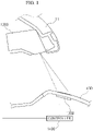
- FIG. 1 is a view for describing a projection switching device according to a first embodiment of the present invention.
- the projection switching device in order to secure a degree of freedom of surface treatment on a switch disposed in a dashboard of a vehicle and diversify implemented images, includes a projection 1200, a plurality of touch sensors 1300, and a controller 1400.
- a microcontroller unit (MCU) of the vehicle may be used as the controller 1400 in the first embodiment of the present invention, but the controller 1400 is not limited thereto, and a separate digital signal processor (DSP) may also be used as the controller 1400.
- DSP digital signal processor
- the projection 1200 projects a symbol on a lower garnish 630. Meanwhile, preferably, the projection 1200 may be disposed at an inner side of an upper dashboard 11 so as not to be exposed to a gaze of a driver.
- the lower garnish 630 covers a lower dashboard 13 and displays control information output from the projection 1200.
- the plurality of touch sensors 1300 are disposed on a lower portion of the lower garnish 630 to sense a touch by a user.
- the controller 1400 When the user's touch sensed by the touch sensor 1300 and symbol information projected through the projection 1200 are input, the controller 1400 outputs control information that corresponds to information on the user's touch to the corresponding device.
- the projection switching device further includes a reference position providing portion 1500 (may also be referred to as reference position provider) configured to project a position correcting symbol on the lower garnish 630.
- the reference position providing portion 1500 may have a projection area disposed at one side of the lower garnish 630 and may display a correcting symbol on the lower garnish 630 through a backlight 1510. Meanwhile, the reference position providing portion 1500 may also display the correcting symbol through a light emitting diode (LED) disposed on the lower garnish 630.
- LED light emitting diode
- a microcontroller unit (MCU) of the vehicle may be used as the reference position providing portion 1500, but the reference position providing portion 1500 is not limited thereto.
- a separate digital signal processor (DSP) may also be used as the reference position providing portion 1500.
- DSP separate digital signal processor
- DSP may also be used for both the controller 1400 and the reference position providing portion 1500.
- the controller 1400 may allow a user to adjust a variation in a projected image using a keystone adjustment function of the projection 1200.
- the plurality of touch sensors 1300 may also be a single touchpad having a plurality of touch areas.
- the projection 1200-type switch by implementing the projection 1200-type switch, usability of the device can be improved, and an error rate of the device can be reduced through position correction.
- the controller 1400 controls the output of the projection 1200 so that default symbol information is output on the lower garnish 630.
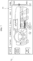
- the projection 1200 projects a symbol set by the controller 1400 on the lower garnish 630.
- a menu such as A/VENT, MONITOR, TABLE, LIGHT, and HOME and symbols such as VENT MODE, DEF MODE, on/off of an air conditioning system, and an air conditioning strength control bar (maximum, minimum) are projected on the lower garnish 630.
- FIG. 3 is only an embodiment, and the symbols are not limited thereto.
- the touch sensors 1300 configured to recognize the user's touch are installed on lower portions of the symbols projected on the lower garnish 630.
- the touch sensor 1300 installed on the lower portion of the lower garnish 630 recognizes the user's touch and provides the information to the controller 1400.
- the controller 1400 checks information on the user's touch sensed by the touch sensor 1300 and information on the symbol projected through the projection 1200 and provides control information corresponding to the touch information to the corresponding device.
- control interface information corresponding to the symbol selected by the driver or passenger (a 3D PATTERN menu button symbol and a subordinate interface thereof (3D PATTERN on/off, Fixed/Dynamic, a R control bar, a G control bar, a B control bar, and a brightness control bar), and a REAL METAL menu button symbol) are displayed on the lower garnish 630.
- the projection switching device may correct an erroneous touch due to projected symbol information.
- the projection 1200 according to the first embodiment of the present invention is installed in the upper dashboard of the vehicle, a variation in the projection area of the projection 1200 due to an initial assembly error or vibration of the vehicle inevitably occurs.
- the projection switching device further includes the reference position providing portion 1500 configured to project a position correcting symbol on the lower garnish 630 to correct a variation in the projection area of the projection 1200, and the controller 1400 may allow the user to adjust a variation in a projected image using a keystone adjustment function of the projection 1200.
- FIG. 5 is a view illustrating a state in which a symbol is abnormally projected through the projection 1200. As illustrated in FIG. 5 , a variation may occur between a symbol PT projected through the projection 1200 and a recognition area SA of the touch sensor 1300 disposed on the lower portion of the lower garnish.
- a light transmitting area 1600 is disposed at one side of the lower garnish 630, and a position correcting symbol is displayed on the lower garnish 630 through the backlight at a lower portion.
- a variation may occur between the area PT of the projected image that is projected from the projection 1200 and the area SA of the touch sensor 1300 that is disposed on the lower portion of the lower garnish 630.
- the driver switches to a variation adjustment mode to correct the position of the projected image output from the projection 1200.
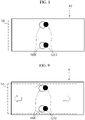
- a position correcting symbol 1600 is output on the light transmitting area on the lower garnish 630, and a correcting symbol 1210 is projected on the lower garnish 630 through the projection 1200.
- the driver may check an error in an image through the two symbols 1600 and 1210.
- the driver may select top, bottom, left, and right arrow symbols 1600, which are displayed in the light transmitting area, to, as illustrated in FIG. 9 , adjust the position of the projected image of the projection 1200.
- a switching symbol of the vehicle is projected through the projection 1200.
- a method of completing the position correction mode may be implemented in various ways. For example, all the symbols for position correction of the projected image may be selected to complete the position correction mode, or a separate "complete" button may be output and the button may be selected to complete the position correction mode.
- the projection switching device may be independently provided or provided at an outer side of a range in which a connection frame 500 connected to a monitor slides according to a first embodiment to a third embodiment.
- a projection switching device capable of securing a degree of freedom of surface treatment on a switch disposed in a dashboard of a vehicle and diversifying implemented images.
Landscapes
- Engineering & Computer Science (AREA)
- Mechanical Engineering (AREA)
- Chemical & Material Sciences (AREA)
- Combustion & Propulsion (AREA)
- Transportation (AREA)
- Theoretical Computer Science (AREA)
- General Physics & Mathematics (AREA)
- Physics & Mathematics (AREA)
- General Engineering & Computer Science (AREA)
- Human Computer Interaction (AREA)
- Computer Hardware Design (AREA)
- Instrument Panels (AREA)
- Projection Apparatus (AREA)
Abstract
Disclose are projection switching devices including a projection configured to project a symbol on a lower garnish, the lower garnish configured to cover a lower dashboard and to display control information projected from the projection, touch sensors disposed on a lower portion of the lower garnish to sense a touch of a user, and a controller configured to output control information corresponding to symbol information at a position where the touch has occurred to a corresponding device, in response to the touch being sensed by the touch sensor.

Description
- This application claims the benefit of
Korean Patent Application No. 10-2020-0133668, filed on Oct 15, 2020 - The following description relates to a projection switching device, and more particularly, to a switching device providing a touch switch inside a vehicle.
- Generally, a center fascia which displays Audio Video Navigation (AVN) functions, navigation functions, and air conditioning control functions of a vehicle to a driver to allow the driver to control such functions is mounted in a fixed state on a dashboard of the vehicle.
- In a conventional dashboard, an operation switch is provided as a backlight type on a lower portion of the dashboard, and since a switch symbol is implemented through masking, there are problems in that it is not possible to change the shape and a limitation occurs in surface treatment for visibility of an image projected by the backlight.
- This Summary is provided to introduce a selection of concepts in a simplified form that are further described below in the Detailed Description. This Summary is not intended to identify key features or essential features of the claimed subject matter, nor is it intended to be used as an aid in determining the scope of the claimed subject matter.
- In one general aspect, there is provided a projection switching device including a projection configured to project a symbol on a lower garnish, the lower garnish configured to cover a lower dashboard and to display control information projected from the projection, touch sensors disposed on a lower portion of the lower garnish to sense a touch of a user, and a controller configured to output control information corresponding to symbol information at a position where the touch has occurred to a corresponding device, in response to the touch being sensed by the touch sensor.
- The projection may be disposed at an inner side of an upper dashboard.
- The projection switching device may include a reference position provider configured to project a position correcting symbol on the lower garnish, wherein the controller may be configured to adjust a variation in a projected image using a keystone adjustment function of the projection.
- The reference position provider may include a projection area disposed at a side of the lower garnish and is further configured to display a correcting symbol on the lower garnish through a backlight.
- The reference position provider may be configured to display a correcting symbol through a light emitting diode (LED) disposed on the lower garnish.
- The touch sensors may constitute a single touchpad comprising a plurality of touch areas.
- In response to correcting a variation in the projection area, the controller may be configured to switch to a variation adjustment mode for position correction of a projected image that is output from the projection, to project the correcting symbol for position correction from the projection on to the lower garnish, and to enable the position of the projected image to be adjusted according to a touch of the user.
- The projection may be configured to not be exposed to a gaze of the user.
- Other features and aspects will be apparent from the following detailed description, the drawings, and the claims.
-
-
FIG. 1 is a view for describing a projection switching device according to an embodiment. -
FIGS. 2 to 6 are reference diagrams for describing an operational process of the projection switching device according to an embodiment. -
FIGS. 7 to 10 are reference diagrams for describing a variation adjustment process in the projection switching device according to an embodiment. - Throughout the drawings and the detailed description, unless otherwise described or provided, the same drawing reference numerals will be understood to refer to the same elements, features, and structures. The drawings may not be to scale, and the relative size, proportions, and depiction of elements in the drawings may be exaggerated for clarity, illustration, and convenience.
- The following detailed description is provided to assist the reader in gaining a comprehensive understanding of the methods, apparatuses, and/or systems described herein. However, various changes, modifications, and equivalents of the methods, apparatuses, and/or systems described herein will be apparent after an understanding of the disclosure of this application. For example, the sequences of operations described herein are merely examples, and are not limited to those set forth herein, but may be changed as will be apparent after an understanding of the disclosure of this application, with the exception of operations necessarily occurring in a certain order. Also, descriptions of features that are known may be omitted for increased clarity and conciseness.
- The features described herein may be embodied in different forms, and are not to be construed as being limited to the examples described herein. Rather, the examples described herein have been provided merely to illustrate some of the many possible ways of implementing the methods, apparatuses, and/or systems described herein that will be apparent after an understanding of the disclosure of this application.
- The terminology used herein is for the purpose of describing particular examples only and is not to be limiting of the examples. The singular forms "a", "an", and "the" are intended to include the plural forms as well, unless the context clearly indicates otherwise. It will be further understood that the terms "comprises/comprising" and/or "includes/including" when used herein, specify the presence of stated features, integers, steps, operations, elements, and/or components, but do not preclude the presence or addition of one or more other features, integers, steps, operations, elements, components and/or groups thereof.
- Also, in the description of the components, terms such as first, second, A, B, (a), (b) or the like may be used herein when describing components of the present disclosure. These terms are used only for the purpose of discriminating one constituent element from another constituent element, and the nature, the sequences, or the orders of the constituent elements are not limited by the terms. When one constituent element is described as being "connected", "coupled", or "attached" to another constituent element, it should be understood that one constituent element can be connected or attached directly to another constituent element, and an intervening constituent element can also be "connected", "coupled", or "attached" to the constituent elements.
- When describing the examples with reference to the accompanying drawings, like reference numerals refer to like constituent elements and a repeated description related thereto will be omitted. In the description of examples, detailed description of well-known related structures or functions will be omitted when it is deemed that such description will cause ambiguous interpretation of the present disclosure.
- The same name may be used to describe an element included in the examples described above and an element having a common function. Unless otherwise mentioned, the descriptions on the examples may be applicable to the following examples and thus, duplicated descriptions will be omitted for conciseness.
-
FIG. 1 is a view for describing a projection switching device according to a first embodiment of the present invention. - As illustrated in
FIG. 1 , in order to secure a degree of freedom of surface treatment on a switch disposed in a dashboard of a vehicle and diversify implemented images, the projection switching device according to the first embodiment of the present invention includes aprojection 1200, a plurality oftouch sensors 1300, and acontroller 1400. Preferably, a microcontroller unit (MCU) of the vehicle may be used as thecontroller 1400 in the first embodiment of the present invention, but thecontroller 1400 is not limited thereto, and a separate digital signal processor (DSP) may also be used as thecontroller 1400. - The
projection 1200 projects a symbol on alower garnish 630. Meanwhile, preferably, theprojection 1200 may be disposed at an inner side of anupper dashboard 11 so as not to be exposed to a gaze of a driver. - Also, the
lower garnish 630 covers a lower dashboard 13 and displays control information output from theprojection 1200. - The plurality of
touch sensors 1300 are disposed on a lower portion of thelower garnish 630 to sense a touch by a user. - When the user's touch sensed by the
touch sensor 1300 and symbol information projected through theprojection 1200 are input, thecontroller 1400 outputs control information that corresponds to information on the user's touch to the corresponding device. - Also, in the first embodiment of the present invention, the projection switching device further includes a reference position providing portion 1500 (may also be referred to as reference position provider) configured to project a position correcting symbol on the
lower garnish 630. Here, the referenceposition providing portion 1500 may have a projection area disposed at one side of thelower garnish 630 and may display a correcting symbol on thelower garnish 630 through a backlight 1510. Meanwhile, the referenceposition providing portion 1500 may also display the correcting symbol through a light emitting diode (LED) disposed on thelower garnish 630. - In an example, a microcontroller unit (MCU) of the vehicle may be used as the reference
position providing portion 1500, but the referenceposition providing portion 1500 is not limited thereto. A separate digital signal processor (DSP) may also be used as the referenceposition providing portion 1500. In another example, separate digital signal processor (DSP) may also be used for both thecontroller 1400 and the referenceposition providing portion 1500. - Thus, preferably, the
controller 1400 may allow a user to adjust a variation in a projected image using a keystone adjustment function of theprojection 1200. - The plurality of
touch sensors 1300 may also be a single touchpad having a plurality of touch areas. - According to the first embodiment of the present invention, by implementing the projection 1200-type switch, usability of the device can be improved, and an error rate of the device can be reduced through position correction.
- Hereinafter, an operational process of the projection switching device according to the first embodiment of the present invention will be described with reference to
FIGS. 2 to 10 . - When the power of the vehicle is turned on, the
controller 1400 controls the output of theprojection 1200 so that default symbol information is output on thelower garnish 630. - Then, as illustrated in
FIG. 2 , theprojection 1200 projects a symbol set by thecontroller 1400 on thelower garnish 630. As illustrated inFIG. 3 , a menu such as A/VENT, MONITOR, TABLE, LIGHT, and HOME and symbols such as VENT MODE, DEF MODE, on/off of an air conditioning system, and an air conditioning strength control bar (maximum, minimum) are projected on thelower garnish 630.FIG. 3 is only an embodiment, and the symbols are not limited thereto. - The
touch sensors 1300 configured to recognize the user's touch are installed on lower portions of the symbols projected on thelower garnish 630. - When the driver or passenger touches a projected symbol, the
touch sensor 1300 installed on the lower portion of thelower garnish 630 recognizes the user's touch and provides the information to thecontroller 1400. - Then, the
controller 1400 checks information on the user's touch sensed by thetouch sensor 1300 and information on the symbol projected through theprojection 1200 and provides control information corresponding to the touch information to the corresponding device. - For example, when the driver or passenger selects LIGHT among the symbols projected on the
lower garnish 630 through theprojection 1200, as illustrated inFIG. 4 , control interface information corresponding to the symbol selected by the driver or passenger (a 3D PATTERN menu button symbol and a subordinate interface thereof (3D PATTERN on/off, Fixed/Dynamic, a R control bar, a G control bar, a B control bar, and a brightness control bar), and a REAL METAL menu button symbol) are displayed on thelower garnish 630. - Meanwhile, the projection switching device according to the first embodiment of the present invention may correct an erroneous touch due to projected symbol information.
- Since the
projection 1200 according to the first embodiment of the present invention is installed in the upper dashboard of the vehicle, a variation in the projection area of theprojection 1200 due to an initial assembly error or vibration of the vehicle inevitably occurs. - Thus, the projection switching device according to the first embodiment of the present invention further includes the reference
position providing portion 1500 configured to project a position correcting symbol on thelower garnish 630 to correct a variation in the projection area of theprojection 1200, and thecontroller 1400 may allow the user to adjust a variation in a projected image using a keystone adjustment function of theprojection 1200. -
FIG. 5 is a view illustrating a state in which a symbol is abnormally projected through theprojection 1200. As illustrated inFIG. 5 , a variation may occur between a symbol PT projected through theprojection 1200 and a recognition area SA of thetouch sensor 1300 disposed on the lower portion of the lower garnish. - Thus, in order to adjust the variation between the projected image that is projected through the
projection 1200 and the recognition area of the touch sensor, as illustrated inFIG. 6 , alight transmitting area 1600 is disposed at one side of thelower garnish 630, and a position correcting symbol is displayed on thelower garnish 630 through the backlight at a lower portion. - Then, as illustrated in
FIG. 7 , a variation may occur between the area PT of the projected image that is projected from theprojection 1200 and the area SA of thetouch sensor 1300 that is disposed on the lower portion of thelower garnish 630. - Thus, the driver switches to a variation adjustment mode to correct the position of the projected image output from the
projection 1200. - Then, as illustrated in
FIG. 8 , aposition correcting symbol 1600 is output on the light transmitting area on thelower garnish 630, and a correctingsymbol 1210 is projected on thelower garnish 630 through theprojection 1200. Thus, the driver may check an error in an image through the twosymbols - Then, in order to adjust a variation in a projected image that is projected through the
projection 1200, the driver may select top, bottom, left, andright arrow symbols 1600, which are displayed in the light transmitting area, to, as illustrated inFIG. 9 , adjust the position of the projected image of theprojection 1200. - After the variation in the position of the projected image projected from the
projection 1200 is completely corrected, as illustrated inFIG. 10 , a switching symbol of the vehicle is projected through theprojection 1200. Here, a method of completing the position correction mode may be implemented in various ways. For example, all the symbols for position correction of the projected image may be selected to complete the position correction mode, or a separate "complete" button may be output and the button may be selected to complete the position correction mode. - The projection switching device according to the first embodiment of the present invention may be independently provided or provided at an outer side of a range in which a connection frame 500 connected to a monitor slides according to a first embodiment to a third embodiment.
- As described above, by implementing a projection-type switch, it is possible to improve usability of a device and reduce an error rate of the device through position correction.
- As described above, according to an example, here is provided a projection switching device capable of securing a degree of freedom of surface treatment on a switch disposed in a dashboard of a vehicle and diversifying implemented images.
- While this disclosure includes specific examples, it will be apparent after an understanding of the disclosure of this application that various changes in form and details may be made in these examples without departing from the spirit and scope of the claims and their equivalents. The examples described herein are to be considered in a descriptive sense only, and not for purposes of limitation. Descriptions of features or aspects in each example are to be considered as being applicable to similar features or aspects in other examples. Suitable results may be achieved if the described techniques are performed in a different order, and/or if components in a described system, architecture, device, or circuit are combined in a different manner, and/or replaced or supplemented by other components or their equivalents. Therefore, the scope of the disclosure is defined not by the detailed description, but by the claims and their equivalents, and all variations within the scope of the claims and their equivalents are to be construed as being included in the disclosure.
Claims (8)
- A projection switching device comprising:a projection configured to project a symbol on a lower garnish;the lower garnish configured to cover a lower dashboard and to display control information projected from the projection;touch sensors disposed on a lower portion of the lower garnish to sense a touch of a user; anda controller configured to output control information corresponding to symbol information at a position where the touch has occurred to a corresponding device, in response to the touch being sensed by the touch sensor.
- The projection switching device of claim 1, wherein the projection is disposed at an inner side of an upper dashboard.
- The projection switching device of claim 1, further comprising a reference position provider configured to project a position correcting symbol on the lower garnish,
wherein the controller is further configured to adjust a variation in a projected image using a keystone adjustment function of the projection. - The projection switching device of claim 3, wherein the reference position provider comprises a projection area disposed at a side of the lower garnish and is further configured to display a correcting symbol on the lower garnish through a backlight.
- The projection switching device of claim 3, wherein the reference position provider is further configured to display a correcting symbol through a light emitting diode (LED) disposed on the lower garnish.
- The projection switching device of claim 1, wherein the touch sensors constitute a single touchpad comprising a plurality of touch areas.
- The projection switching device of claim 3, wherein, in response to correcting a variation in the projection area, the controller is further configured to switch to a variation adjustment mode for position correction of a projected image that is output from the projection, to project the correcting symbol for position correction from the projection on to the lower garnish, and to enable the position of the projected image to be adjusted according to a touch of the user.
- The projection switching device of claim 2, wherein the projection is further configured to not be exposed to a gaze of the user.
Applications Claiming Priority (1)
| Application Number | Priority Date | Filing Date | Title |
|---|---|---|---|
| KR1020200133668A KR20220049936A (en) | 2020-10-15 | 2020-10-15 | Vehicle sliding module assembly |
Publications (1)
| Publication Number | Publication Date |
|---|---|
| EP3984804A1 true EP3984804A1 (en) | 2022-04-20 |
Family
ID=78483122
Family Applications (1)
| Application Number | Title | Priority Date | Filing Date |
|---|---|---|---|
| EP21202888.0A Pending EP3984804A1 (en) | 2020-10-15 | 2021-10-15 | Projection switching device |
Country Status (4)
| Country | Link |
|---|---|
| US (1) | US11874979B2 (en) |
| EP (1) | EP3984804A1 (en) |
| KR (1) | KR20220049936A (en) |
| CN (1) | CN114368286B (en) |
Families Citing this family (1)
| Publication number | Priority date | Publication date | Assignee | Title |
|---|---|---|---|---|
| FR3159116B1 (en) * | 2024-02-14 | 2026-02-13 | Faurecia Interieur Ind | Upholstery element including a modular touch interface |
Citations (2)
| Publication number | Priority date | Publication date | Assignee | Title |
|---|---|---|---|---|
| US20200192466A1 (en) * | 2017-08-08 | 2020-06-18 | Marelli Automotive Lighting Italy S.p.A. | Virtual Human-Machine Interface System and Corresponding Virtual Human-Machine Interface Method for a Vehicle |
| DE102019200632A1 (en) * | 2019-01-18 | 2020-07-23 | Audi Ag | Operating system with portable interface unit and motor vehicle with the operating system |
Family Cites Families (21)
| Publication number | Priority date | Publication date | Assignee | Title |
|---|---|---|---|---|
| US6141000A (en) * | 1991-10-21 | 2000-10-31 | Smart Technologies Inc. | Projection display system with touch sensing on screen, computer assisted alignment correction and network conferencing |
| JP2000089913A (en) * | 1998-09-08 | 2000-03-31 | Gunze Ltd | Touch panel input coordinate converting device |
| JP3742027B2 (en) * | 2002-04-08 | 2006-02-01 | Necビューテクノロジー株式会社 | Projection image distortion correction method, distortion correction program, and projection-type image display device |
| JP3761491B2 (en) * | 2002-05-10 | 2006-03-29 | Necビューテクノロジー株式会社 | Projection image distortion correction method, distortion correction program, and projection-type image display device |
| US7256772B2 (en) * | 2003-04-08 | 2007-08-14 | Smart Technologies, Inc. | Auto-aligning touch system and method |
| JP4037816B2 (en) * | 2003-10-06 | 2008-01-23 | Necディスプレイソリューションズ株式会社 | Projector and method of projecting screen by projector |
| JP5457941B2 (en) * | 2009-08-06 | 2014-04-02 | キヤノン株式会社 | Information processing apparatus and information processing apparatus control method |
| JP2011065025A (en) * | 2009-09-18 | 2011-03-31 | Sanyo Electric Co Ltd | Projection type image display device |
| JP2011205524A (en) * | 2010-03-26 | 2011-10-13 | Seiko Epson Corp | Projector device, and projection method thereof |
| KR101125384B1 (en) * | 2010-08-19 | 2012-03-27 | 현대자동차주식회사 | Electronic recognition switch system for vehicle, and position correcting method thereof |
| TWI454999B (en) * | 2011-11-21 | 2014-10-01 | Wistron Corp | An optical touch display, a calibration apparatus and a calibration method thereof |
| JP6244822B2 (en) * | 2013-10-30 | 2017-12-13 | トヨタ車体株式会社 | In-vehicle display system |
| US10664100B2 (en) * | 2014-07-31 | 2020-05-26 | Hewlett-Packard Development Company, L.P. | Misalignment detection |
| US20160085332A1 (en) | 2014-09-23 | 2016-03-24 | Continental Automotive Systems Inc. | Touch sensitive holographic display system and method of using the display system |
| US11106314B2 (en) * | 2015-04-21 | 2021-08-31 | Dell Products L.P. | Continuous calibration of an information handling system projected user interface |
| CN107454373B (en) * | 2016-05-31 | 2019-06-14 | 财团法人工业技术研究院 | Projection system and non-planar automatic correction method and automatic correction processing device thereof |
| DE202018007013U1 (en) | 2017-12-12 | 2025-11-13 | Marquardt GmbH | Operating device |
| JP2019125955A (en) * | 2018-01-18 | 2019-07-25 | キヤノン株式会社 | Parameter generation apparatus, control method therefor, and program |
| JP6784280B2 (en) * | 2018-06-27 | 2020-11-11 | セイコーエプソン株式会社 | Projector and projector control method |
| US11148489B2 (en) * | 2018-10-09 | 2021-10-19 | Ford Global Technologies, Llc | Hitch assist system |
| KR102038020B1 (en) * | 2019-09-19 | 2019-10-30 | 주식회사 서연이화 | A smart garnish for an automobile |
-
2020
- 2020-10-15 KR KR1020200133668A patent/KR20220049936A/en not_active Ceased
-
2021
- 2021-10-15 CN CN202111205915.2A patent/CN114368286B/en active Active
- 2021-10-15 US US17/502,704 patent/US11874979B2/en active Active
- 2021-10-15 EP EP21202888.0A patent/EP3984804A1/en active Pending
Patent Citations (2)
| Publication number | Priority date | Publication date | Assignee | Title |
|---|---|---|---|---|
| US20200192466A1 (en) * | 2017-08-08 | 2020-06-18 | Marelli Automotive Lighting Italy S.p.A. | Virtual Human-Machine Interface System and Corresponding Virtual Human-Machine Interface Method for a Vehicle |
| DE102019200632A1 (en) * | 2019-01-18 | 2020-07-23 | Audi Ag | Operating system with portable interface unit and motor vehicle with the operating system |
Also Published As
| Publication number | Publication date |
|---|---|
| US11874979B2 (en) | 2024-01-16 |
| CN114368286A (en) | 2022-04-19 |
| CN114368286B (en) | 2024-06-04 |
| KR20220049936A (en) | 2022-04-22 |
| US20220121297A1 (en) | 2022-04-21 |
Similar Documents
| Publication | Publication Date | Title |
|---|---|---|
| US12263734B2 (en) | Vehicle input device, vehicle input method, and non-transitory storage medium stored with vehicle input program | |
| US9760270B2 (en) | Vehicular electronic device | |
| US10388249B2 (en) | Multifunctional operating device for displaying a remote application in a vehicle | |
| EP3670237B1 (en) | Vehicle-mounted device operation system | |
| KR20100105293A (en) | Handling device for vehicle | |
| JP2007106353A (en) | Vehicle information display device and vehicle information display system | |
| US10496236B2 (en) | Vehicle display device and method for controlling vehicle display device | |
| JP4858206B2 (en) | In-vehicle device operation support device and operation support method | |
| CN104981379A (en) | Electronic control device | |
| US20160077601A1 (en) | Input system for on-board use | |
| JP2019031118A (en) | In-vehicle equipment operation support system | |
| CN104937531A (en) | Operating method and operating system in a vehicle | |
| JP2000194507A (en) | Touch operation input device | |
| US11874979B2 (en) | Projection switching device | |
| JP2010113568A (en) | Motion detector and operation system using the same | |
| JP5136948B2 (en) | Vehicle control device | |
| JP6018775B2 (en) | Display control device for in-vehicle equipment | |
| JP6610452B2 (en) | Vehicle display device | |
| JP6558380B2 (en) | VEHICLE INPUT DEVICE, INPUT DEVICE, AND CONTROL METHOD FOR VEHICLE INPUT DEVICE | |
| US9600097B2 (en) | On-vehicle device operation apparatus and on-vehicle device operation method | |
| JP2018162023A (en) | Operating device | |
| JP2017187919A (en) | In-vehicle information processing system | |
| JP2017187922A (en) | In-vehicle information processing system | |
| JP2001159954A (en) | Multi-function switch | |
| JP2001013943A (en) | Display controller |
Legal Events
| Date | Code | Title | Description |
|---|---|---|---|
| PUAI | Public reference made under article 153(3) epc to a published international application that has entered the european phase |
Free format text: ORIGINAL CODE: 0009012 |
|
| STAA | Information on the status of an ep patent application or granted ep patent |
Free format text: STATUS: REQUEST FOR EXAMINATION WAS MADE |
|
| 17P | Request for examination filed |
Effective date: 20211015 |
|
| AK | Designated contracting states |
Kind code of ref document: A1 Designated state(s): AL AT BE BG CH CY CZ DE DK EE ES FI FR GB GR HR HU IE IS IT LI LT LU LV MC MK MT NL NO PL PT RO RS SE SI SK SM TR |
|
| RBV | Designated contracting states (corrected) |
Designated state(s): AL AT BE BG CH CY CZ DE DK EE ES FI FR GB GR HR HU IE IS IT LI LT LU LV MC MK MT NL NO PL PT RO RS SE SI SK SM TR |