EP3984789A1 - Propulsion device, flying object, and propulsion method - Google Patents
Propulsion device, flying object, and propulsion method Download PDFInfo
- Publication number
- EP3984789A1 EP3984789A1 EP21753928.7A EP21753928A EP3984789A1 EP 3984789 A1 EP3984789 A1 EP 3984789A1 EP 21753928 A EP21753928 A EP 21753928A EP 3984789 A1 EP3984789 A1 EP 3984789A1
- Authority
- EP
- European Patent Office
- Prior art keywords
- flying body
- propulsion apparatus
- thrusters
- gas generator
- propulsion
- Prior art date
- Legal status (The legal status is an assumption and is not a legal conclusion. Google has not performed a legal analysis and makes no representation as to the accuracy of the status listed.)
- Pending
Links
Images





Classifications
-
- B—PERFORMING OPERATIONS; TRANSPORTING
- B60—VEHICLES IN GENERAL
- B60F—VEHICLES FOR USE BOTH ON RAIL AND ON ROAD; VEHICLES CAPABLE OF TRAVELLING IN OR ON DIFFERENT MEDIA, e.g. AMPHIBIOUS VEHICLES
- B60F5/00—Other vehicles capable of travelling in or on different media
- B60F5/02—Other vehicles capable of travelling in or on different media convertible into aircraft
-
- B—PERFORMING OPERATIONS; TRANSPORTING
- B64—AIRCRAFT; AVIATION; COSMONAUTICS
- B64D—EQUIPMENT FOR FITTING IN OR TO AIRCRAFT; FLIGHT SUITS; PARACHUTES; ARRANGEMENT OR MOUNTING OF POWER PLANTS OR PROPULSION TRANSMISSIONS IN AIRCRAFT
- B64D27/00—Arrangement or mounting of power plants in aircraft; Aircraft characterised by the type or position of power plants
- B64D27/02—Aircraft characterised by the type or position of power plants
- B64D27/023—Aircraft characterised by the type or position of power plants of rocket type, e.g. for assisting taking-off or braking
-
- B—PERFORMING OPERATIONS; TRANSPORTING
- B64—AIRCRAFT; AVIATION; COSMONAUTICS
- B64D—EQUIPMENT FOR FITTING IN OR TO AIRCRAFT; FLIGHT SUITS; PARACHUTES; ARRANGEMENT OR MOUNTING OF POWER PLANTS OR PROPULSION TRANSMISSIONS IN AIRCRAFT
- B64D25/00—Emergency apparatus or devices, not otherwise provided for
-
- B—PERFORMING OPERATIONS; TRANSPORTING
- B64—AIRCRAFT; AVIATION; COSMONAUTICS
- B64D—EQUIPMENT FOR FITTING IN OR TO AIRCRAFT; FLIGHT SUITS; PARACHUTES; ARRANGEMENT OR MOUNTING OF POWER PLANTS OR PROPULSION TRANSMISSIONS IN AIRCRAFT
- B64D27/00—Arrangement or mounting of power plants in aircraft; Aircraft characterised by the type or position of power plants
- B64D27/02—Aircraft characterised by the type or position of power plants
- B64D27/16—Aircraft characterised by the type or position of power plants of jet type
- B64D27/20—Aircraft characterised by the type or position of power plants of jet type within, or attached to, fuselages
-
- B—PERFORMING OPERATIONS; TRANSPORTING
- B64—AIRCRAFT; AVIATION; COSMONAUTICS
- B64G—COSMONAUTICS; VEHICLES OR EQUIPMENT THEREFOR
- B64G1/00—Cosmonautic vehicles
- B64G1/002—Launch systems
-
- B—PERFORMING OPERATIONS; TRANSPORTING
- B64—AIRCRAFT; AVIATION; COSMONAUTICS
- B64G—COSMONAUTICS; VEHICLES OR EQUIPMENT THEREFOR
- B64G1/00—Cosmonautic vehicles
- B64G1/22—Parts of, or equipment specially adapted for fitting in or to, cosmonautic vehicles
- B64G1/40—Arrangements or adaptations of propulsion systems
- B64G1/401—Liquid propellant rocket engines
-
- F—MECHANICAL ENGINEERING; LIGHTING; HEATING; WEAPONS; BLASTING
- F02—COMBUSTION ENGINES; HOT-GAS OR COMBUSTION-PRODUCT ENGINE PLANTS
- F02K—JET-PROPULSION PLANTS
- F02K9/00—Rocket-engine plants, i.e. plants carrying both fuel and oxidant therefor; Control thereof
- F02K9/42—Rocket-engine plants, i.e. plants carrying both fuel and oxidant therefor; Control thereof using liquid or gaseous propellants
- F02K9/44—Feeding propellants
- F02K9/56—Control
-
- F—MECHANICAL ENGINEERING; LIGHTING; HEATING; WEAPONS; BLASTING
- F02—COMBUSTION ENGINES; HOT-GAS OR COMBUSTION-PRODUCT ENGINE PLANTS
- F02K—JET-PROPULSION PLANTS
- F02K9/00—Rocket-engine plants, i.e. plants carrying both fuel and oxidant therefor; Control thereof
- F02K9/42—Rocket-engine plants, i.e. plants carrying both fuel and oxidant therefor; Control thereof using liquid or gaseous propellants
- F02K9/44—Feeding propellants
- F02K9/56—Control
- F02K9/566—Control elements and safety devices, e.g. pressure relief valves
-
- B—PERFORMING OPERATIONS; TRANSPORTING
- B64—AIRCRAFT; AVIATION; COSMONAUTICS
- B64G—COSMONAUTICS; VEHICLES OR EQUIPMENT THEREFOR
- B64G1/00—Cosmonautic vehicles
- B64G1/22—Parts of, or equipment specially adapted for fitting in or to, cosmonautic vehicles
- B64G1/24—Guiding or controlling apparatus, e.g. for attitude control
- B64G1/244—Spacecraft control systems
Definitions
- the present invention relates to a propulsion apparatus, a flying body and a propulsion method.
- Patent Literature 1 discloses a technology to improve automatic rotation of rotary-wing aircraft when an engine of the rotary-wing aircraft fails in flight.
- This rotary-wing aircraft is provided with an engine that propels the rotary-wing aircraft in a direction of travel in emergency. Due to the propulsive force in the direction of travel, the rotary-wing aircraft improves the automatic rotation.
- Patent Literature 2 discloses an attitude control device provided with a thruster.
- an objective is to provide a propulsion apparatus that reduces an impact of a fall of a flying body in emergency, for example in an engine failure.
- a propulsion apparatus is provided with a gas generator and a plurality of thrusters.
- the gas generator generates a combustion gas when at least a part of a flying body satisfies an emergency condition.
- the plurality of thrusters output the combustion gas downward.
- a flying body according to an embodiment to achieve the above objective is provided with the above-mentioned propulsion apparatus.
- a propulsion method includes determining, by a processor, whether at least a part of a flying body satisfies an emergency condition or not.
- the propulsion method further includes generating a combustion gas when the emergency condition is satisfied and outputting the combustion gas downward the at least a part of the flying body.
- the propulsion apparatus can reduce an impact of a fall of a flying body.
- flying cars In recent years, attention has been focused on small flying bodies, so-called flying cars. The inventors have found out that, in an emergency, for example in an engine failure, an impact should be reduced when a flying body landed in order to prevent occupants of the flying body from being injured by a fall. Furthermore, the inventors have found out that, since such a flying body may fly over a city, a fall on a city should be reduced. It should be noted that “landing" may include, not only a landing on a ground, but also a landing on a built structure such as a ship and a landing on a surface of water. In addition, a flying car may include wheels that are configured to drive on a road such as an ordinary road, a highway or the like.
- a flying body 1 As shown in Fig. 1 , a flying body 1 according to an embodiment (for example: a flying car) is provided with a body 40 and a propulsion apparatus 10, that suppress a fall in an emergency, on an underside thereof.
- the propulsion apparatus 10 In an emergency of the flying body 1, for example when an engine is stopped due to a failure or the like, the propulsion apparatus 10 generates a thrust in an upward direction to reduce an impact when the flying body 1 lands.
- the propulsion apparatus 10 when viewing the flying body 1 from below, the propulsion apparatus 10 is provided so as to overlap a center 2 of the flying body 1.
- the center 2 may be a center of mass of the flying body 1 or may be a center of gravity of the flying body 1, for example.
- the propulsion apparatus 10 may be detachably provided to the flying body 1.
- the propulsion apparatus 10 is configured to generate an upward thrust when attached to the flying body 1.
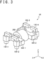
- the propulsion apparatus 10 is provided with a plurality of thrusters 100 (including a first thruster 100-1, a second thruster 100-2, a third thruster 100-3 and a fourth thruster 100-4 for example), a gas generator 200 and manifolds 300 (including a first manifold 300-1 and a second manifold 300-2 for example).
- the thrusters 100 are configured to output a combustion gas, that the gas generator 200 generates, downward when the flying body 1 is flying, in an emergency.
- an upward direction when the flying body 1 is horizontally flying a vertical upper direction for example, as +Z direction
- a forward direction when the flying body 1 is horizontally flying as +X direction
- a direction perpendicular to the Z direction and X direction as Y direction.
- the manifolds 300 are provided so as to sandwich the gas generator 200.
- the first manifold 300-1 is provided in the +X direction from the gas generator 200 and the second manifold 300-2 is provided in the -X direction from the gas generator 200.
- the thrusters 100 are provided so as to sandwich the manifolds 300 and the gas generator 200.
- the first thruster 100-1 and the second thruster 100-2 are provided in the +X direction from the first manifold 300-1.
- the third thruster 100-3 and the fourth thruster 100-4 are provided in the -X direction from the second manifold 300-2.
- the thrusters 100, the manifolds 300 and the gas generator 200 may be provided so as to be overlapped to each other when viewed from the X direction.
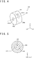
- the gas generator 200 is formed in a pillar shape having an axis parallel to the X axis, such as a cylindrical column shape.
- the gas generator 200 is provided with apertures 210, a first aperture 210-1 and a second aperture 210-2 for example, in a top surface 200a and a bottom surface 200b of the pillar shape.
- the first aperture 210-1 is provided in a geometric center of the top surface 200a for example
- the second aperture 210-2 is provided in a geometric center of the bottom surface 200b for example.
- the gas generator 200 is configured to generate the combustion gas in an emergency.
- the gas generator 200 is provided with fuel 220 and a pressure detector 230 inside.
- the fuel 220 includes a solid fuel for example and, as shown in Fig. 5 , is provided in contact with a side surface of the gas generator 200.
- the fuel 220 has a penetration hole 222 with a pillar shape, a cylindrical column shape for example, of which axis is a segment that connects a geometrical center of the first aperture 210-1 and a geometrical center of the second aperture 210-2.
- the axis of the penetration hole 222 may be parallel to the X axis.
- the gas generator 200 generates the combustion gas by combusting the fuel 220. Arranging the fuel 220 in such a manner can reduce a difference of pressure of the combustion gases outputted from the first aperture 210-1 and the second aperture 210-2.
- the pressure detector 230 measures a pressure inside the gas generator 200.
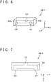
- the first manifold 300-1 is provided with an aperture 310, an aperture 320 and an aperture 321 on X direction side surfaces.
- the aperture 310 is provided to be connected to the first aperture 210-1 of the gas generator 200.
- the aperture 310 may include a geometrical center of a side surface 300b of the first manifold 300-1 in the -X direction for example.
- the aperture 320 and the aperture 321 are provided to a side surface 300a of the first manifold 300-1 in the +X direction for example.
- the first manifold 300-1 is configured to send the combustion gas that the gas generator 200 generates to the thrusters 100, for example the first thruster 100-1 and the second thruster 100-2.
- the first manifold 300-1 is provided with a piping 330 that connects the aperture 310, the aperture 320 and the aperture 321.
- the piping 330 is configured to guide the combustion gas, that the gas generator 200 generates, from the aperture 310 to the aperture 320 and the aperture 321.
- the second manifold 300-2 is configured to send the combustion gas that the gas generator 200 generates to the thrusters 100, for example the third thruster 100-3 and the fourth thruster 100-4.
- the second manifold 300-2 has a configuration of the first manifold 300-1 inverted in the X direction.
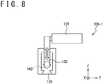
- the first thruster 100-1 is provided with an actuator 110, a pintle valve 120 and a valve body 130.
- the actuator 110 is configured to make a valve opening of the pintle valve 120 change by moving the valve body 130.
- the actuator 110 moves the valve body 130 along the Z axis.
- the valve opening of the pintle valve 120 changes.
- the first thruster 100-1 is configured to output the combustion gas, that the gas generator 200 generates, from the pintle valve 120.
- the first thruster 100-1 is provided with an aperture 140 configured to connect to the aperture 320 of the first manifold 300-1.
- the combustion gas that the gas generator 200 generates is sent from the aperture 140 to inside of the first thruster 100-1 and outputted from the pintle valve 120.
- the output of the combustion gas changes based on the valve opening of the pintle valve 120.
- thrusters 100 for example the second thruster 100-2, the third thruster 100-3 and the fourth thruster 100-4, have a configuration similar to the one of the first thruster 100-1.
- the aperture 140 of the second thruster 100-2 is configured to connect to the aperture 321 of the first manifold 300-1.
- the aperture 140 of the third thruster 100-3 is configured to connect to the aperture 320 of the second manifold 300-2.
- the aperture 140 of the fourth thruster 100-4 is configured to connect to the aperture 321 of the second manifold 300-2.
- Each thruster 100 is configured to output the combustion gas, that the gas generator 200 generates, from the pintle valve 120 based on the valve opening of the pintle valve 120.
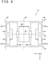
- the gas generator 200 may be provided to overlap a center 68 of the propulsion apparatus 10 when viewed from the +Z direction.
- the center 68 includes for example an intersection of a center line 60 of the propulsion apparatus 10 in the X direction and a center line 50 of the propulsion apparatus 10 in the Y direction.
- the center line 60 of the propulsion apparatus 10 in the X direction is located between a straight line 62 that passes through an edge in the +X direction and is parallel to the Y axis and a straight line 64 that passes through an edge in the -X direction and is parallel to the Y axis.
- a distance from the center line 60 to the straight line 62 is equal to a distance from the center line 60 to the straight line 64.
- the center line 50 of the propulsion apparatus 10 in the Y direction is located between a straight line 54 that passes through an edge in the +Y direction and is parallel to the X axis and a straight line 52 that passes through an edge in the -Y direction and is parallel to the X axis.
- a distance from the center line 50 to the straight line 54 is equal to a distance from the center line 50 to the straight line 52.
- the center 68 may be a geometrical center of the propulsion apparatus 10 viewed from the Z direction.
- the actuators 110 of the thrusters 100 may be extended toward the center line 50 or the center line 60 when viewed from the +Z direction.
- the actuator 110 of the first thruster 100-1 is extended from a location of the pintle valve 120 toward the center line 50 when viewed from the +Z direction.
- the actuators 110 in other thrusters 100 are similarly extended from locations of the pintle valves 120 toward the center line 50.
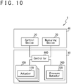
- the propulsion apparatus 10 is provided with a controller 400 that starts the gas generator 200.
- the controller 400 receives various types of status information from a measuring device 20 provided to the body 40 of the flying body 1.
- the status information includes, for example, an altitude, a speed, a tilt (including for example pitch, roll, yaw or the like), a location (including for example latitude, longitude or the like) or the like of the flying body 1.
- the controller 400 determines whether to start the gas generator 200 or not based on the status information of the flying body 1.
- the controller 400 may receive an emergency signal from a control device 30 and start the gas generator 200 based on the emergency signal.
- the controller 400 controls the output of the thrusters 100 based on a pressure in the gas generator 200 and the status information of the flying body 1.
- the controller 400 receives information that indicates the pressure in the gas generator 200 from the pressure detector 230.
- the controller 400 receives the status information of the flying body 1 from the measuring device 20.
- the controller 400 controls the actuators 110 based on the information that indicates the pressure in the gas generator 200 and the status information of the flying body 1.
- the output of the thrusters 100 is controlled based on the control of the actuators 110.
- the controller 400 includes a computer for example.
- the controller 400 is provided with a communication device 401, an input output device 402, a storage device 403 and a processor 404.
- the communication device 401 performs communications with other devices, for example the measuring device 20, the actuators 110 or the like.
- the communication device 401 transfers information received from the measuring device 20, the control device 30 and the pressure detector 230 to the processor 404.
- the communication device 401 transfers a control signal that the processor 404 generates to the actuators 110.
- the control signal includes, for example, information that indicates an output level of each thruster 100.
- the communication device 401 includes various types of interfaces such as Network Interface Card (NIC), Universal Serial Bus (USB) or the like.
- the input output device 402 includes various types of input devices and output devices, for example a keyboard, a mouse, a microphone, a display, a speaker, a touch panel or the like.
- the input output device 402 may be omitted.
- the storage device 403 stores various types of data for controlling the propulsion apparatus 10, for example a control program 500.
- the storage device 403 is used as a non-transitory tangible storage medium that stores the control program 500.
- the control program 500 may be provided as a computer program product stored in a computer readable storage medium 3, or may be provided as a computer program product that is downloadable from a server.
- the processor 404 performs various types of data processes for controlling the propulsion apparatus 10.
- the processor 404 reads the control program 500 from the storage device 403, executes it and generates the control signal for controlling the propulsion apparatus 10.
- the processor 404 includes a Central Processing Unit (CPU) or the like.
- the processor 404 executes the process shown in Fig. 12 by executing the control program 500.
- the processor 404 starts the process shown in Fig 12 when the flying body 1 starts flying, for example.
- step S110 the processor 404 determines whether an emergency condition is satisfied.
- the processor 404 executes a process in step S120.
- no emergency condition (S110: No)
- the processor 404 waits until an emergency condition is satisfied.
- the emergency condition may include that an engine of the flying body 1 is stopped. It may be determined whether an emergency condition is satisfied based on the altitude of the flying body 1.
- the emergency condition may include that the altitude of the flying body 1 is lower than a set altitude.
- the emergency condition may include that the controller 400 receives an emergency signal from the control device 30.
- the emergency condition may be satisfied by a combination of above, for example when the engine is stopped and the altitude of the flying body 1 is lower than the set altitude.
- step S120 the processor 404 starts the gas generator 200.
- the gas generator 200 combusts the fuel 220 and generates the combustion gas.
- the generated combustion gas is supplied to each thruster 100 through the manifolds 300.
- the processor 404 controls an attitude of the flying body 1 by controlling the thrusters 100.
- the processor 404 controls the outputs of the thrusters 100 based on the status information from the measuring device 20, for example the tilt of the flying body 1.
- the processor 404 controls the tilt of the flying body 1 by controlling the thrusters 100.
- the processor 404 controls the output of each thruster 100 so that the upper direction (the Z direction) of the flying body 1 is perpendicular to the ground surface. For example, when the Z direction is tilted forward, the output of the first thruster 100-1 and the output of the second thruster 100-2 are controlled to become greater than the output of the third thruster 100-3 and the output of the fourth thruster 100-4.
- the processor 404 controls the outputs of the thrusters 100 so as to reduce a decent speed of the flying body 1.
- the processor 404 controls the outputs of the thrusters 100 based on the status information received from the measuring device 20, for example the altitude and the speed of the flying body 1.
- the processor 404 makes the outputs of the thrusters 100 greater and reduces the decent speed of the flying body 1.
- the processor 404 may control the thrusters 100 so that the altitude of the flying body 1 is lowered without rising of the flying body 1.
- the processor 404 may control the thrusters 100 so that the impact when the flying body 1 touches down becomes smaller than an impact of a parachute decent.
- the processor 404 may control the thrusters 100 so that the impact when the flying body 1 touches down becomes smaller than an impact when it falls from an altitude of 3 meters.
- the processor 404 may control the thrusters 100 so that the impact when the flying body 1 touches down becomes smaller than an impact when it falls from an altitude of 1 meter.
- step S140 the processor 404 determines whether the flying body 1 is landed.
- the processor 404 may determine whether the flying body 1 is in contact with the ground based on the status information received from the measuring device 20, for example the altitude of the flying body 1.
- the processor 404 determines that the flying body 1 is not in contact with the ground (step S140: No)
- the processor 404 performs the process of the step S130 until the flying body 1 becomes in contact with the ground.
- step S140: Yes the processor 404 executes a process of step S150.
- step S150 the processor 404 reduces the outputs of the thrusters 100 so that the flying body 1 does not rise.
- the outputs of the thrusters 100 after being reduced may be determined in accordance with a weight of the flying body 1. For example, a thrust generated by the thrusters 100 at the reduced outputs may be less than or equal to a gravity applied to the flying body 1.
- the processor 404 may carry on driving the thrusters 100 with the outputs by which the flying body 1 does not rise until the fuel 220 inside the gas generator 200 runs out.
- the processor 404 may reduce the outputs of the thrusters 100 until the thrusters 100 stop.
- the flying body 1 can reduce the impact due to a fall in an emergency by providing the propulsion apparatus 10.
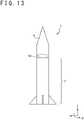
- a flying body 1 may be provided with one or more boosters 5 and a payload 6.
- the flying body 1 may include a rocket or a missile.
- the boosters 5 accelerate the flying body 1 and separate from the payload 6 while the flying body 1 is flying.
- the boosters 5 separate from the payload 6 when the fuel for accelerating the flying body 1 runs out.
- a cylindrical coordinate system with the upper direction of the flying body 1 when it is flying, for example the direction of travel, as the +Z direction.
- the Z axis passes through a center of the flying body 1 and a r direction indicates a distance from the Z axis.
- a ⁇ direction indicates a rotation direction with the Z axis as a center.
- the propulsion apparatus 10 is provided to a booster 5 that separates when the flying body 1 flies.
- the propulsion apparatus 10 may be provided at an end of the booster 5 in the +Z direction, for example at an edge of the booster 5 in the +Z direction.
- the propulsion apparatus 10 may be configured so that the booster 5 is mountable on a bottom part of the propulsion apparatus 10.
- the propulsion apparatus 10 may be provided at a location where the booster 5 is separated from the flying body 1.
- a propulsion apparatus 10 may be provided to each booster 5.
- the propulsion apparatus 10 may control a position where the booster 5 falls.
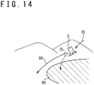
- the booster 5 falls, after being separated from the flying body 1, along the trajectory 70.
- the propulsion apparatus 10 controls the position where the booster 5 falls so that the booster 5 falls outside a range of the area 90.
- the propulsion apparatus 10 controls the position where the booster 5 falls so that the booster 5 falls outside a range of the area 90.
- the booster 5 falls along a corrected trajectory 80 outside the range of the area 90. As a result, the impact due to the fall of the booster 5 can be reduced.
- the propulsion apparatus 10 may be configured to generate thrust in upper direction when mounted to the booster 5. As shown in Fig. 15 , the propulsion apparatus 10 is provided with a plurality of thrusters 100, a gas generator 200 and a manifold 300. The thrusters 100 are configured to output, in an emergency, for example when it is predicted that the booster 5 will fall to the area 90, the combustion gas that the gas generator 200 generates, downward with respect to the flying body 1 during a flight.
- the gas generator 200 is provided at an end of the booster 5 in the +Z direction and is supported by the booster 5.
- the gas generator 200 is formed in a pillar shape, for example a cylindrical column shape, with an axis parallel to the Z axis.
- the gas generator 200 is configured to generate a combustion gas in an emergency, similarly to the embodiment 1.
- the gas generator 200 is provided inside with a fuel 220 and a pressure detector 230.
- the fuel 220 includes for example a solid fuel and the gas generator 200 generates the combustion gas by combusting the fuel 220.
- the manifold 300 is configured to send the combustion gas that the gas generator 200 generates to the thrusters 100, similarly to the embodiment 1.
- the manifold 300 is provided for example at an end of the gas generator 200 in the +Z direction.
- the thrusters 100 are configured to output the combustion gas that the gas generator 200 generates from pintle valves 120, similarly to the embodiment 1.
- the thrusters 100 controls outputs of the combustion gas by control of valve openings of the pintle valves 120 by actuators 110.
- Each thruster 100 may be provided to the manifold 300 in the +Z direction. As shown in Fig. 16 , each thruster 100 may be arranged to be in a rotational symmetry, for example in a quadruple rotational symmetry, around the Z axis. As a result, the attitude and the fall position of the booster 5 can be controlled by controlling outputs of the thrusters 100.
- the thrusters 100, the manifold 300 and the gas generator 200 may be provided to overlap each other when viewed from the Z direction. As a result, a surface of the propulsion apparatus 10 when viewed from the +Z direction, that is the direction of travel of the flying body 1, becomes smaller and an air resistance of the flying body 1 can be reduced.
- the propulsion apparatus 10 may be provided with a controller 400 that starts the gas generator 200 and a measuring device 20 that measures a status of the booster 5.
- the controller 400 receives various types of status information from the measuring device 20 and determines whether to start the gas generator 200 or not based on the status information, similarly to the embodiment 1.
- the measuring device 20 may be provided to the booster 5.
- the controller 400 controls the outputs of the thrusters 100 based on an inner pressure in the gas generator 200 and the status information of the booster 5, similarly to the embodiment 1. As details are similar to the embodiment 1, description thereof will be omitted.
- the processor 404 of the controller 400 executes the control program 500, similarly to the embodiment 1.
- the processor 404 executes the control program 500 to execute the process shown in Fig. 18 .
- the processor 404 starts the process shown in Fig. 18 when the flying body 1 starts flying, for example.
- step S110 the processor 404 determines whether an emergency condition is satisfied. When an emergency condition is satisfied (S110: Yes), the processor 404 executes a process in step S120. When no emergency condition is satisfied (S110: No), the processor 404 waits until an emergency condition is satisfied.
- the emergency condition may include a possibility that the booster 5 may fall in the area 90.
- the processor 404 predicts a fall position of the booster 5 based on the status information, for example a position (for example a latitude, a longitude and a height) and a speed, of the booster 5.
- the processor 404 determines whether an emergency condition is satisfied based on the predicted fall position of the booster 5. For example, when the predicted fall position is included in the area 90, the processor 404 determines that the emergency condition is satisfied.
- step S120 the processor 404 starts the gas generator 200.
- the gas generator 200 combusts the fuel 220 and generates the combustion gas.
- the generated combustion gas is supplied to each thruster 100 through the manifold 300.
- step S130 the processor 404 controls an attitude of the booster 5 by controlling the thrusters 100.
- the processor 404 controls the outputs of the thrusters 100 based on the status information from the measuring device 20, for example the tilt of the booster 5.
- the processor 404 may control the outputs of the thrusters 100 based on the position of the booster 5.
- the processor 404 controls the fall position of the booster 5 by controlling the outputs of the thrusters 100.
- the processor 404 controls the thrusters 100 so that the booster 5 does not fall in the area 90.
- the processor 404 controls the outputs of the thrusters 100 based on the status information from the measuring device 20, for example the position and the speed of the booster 5.
- the processor 404 calculates the corrected trajectory 80 along which the booster 5 is made to fall outside the range of the area 90, based on the position and the speed of the booster 5.
- the processor 404 controls the thrusters 100 so that the booster 5 moves along the calculated corrected trajectory 80.
- the processor 404 may control the outputs of the thrusters 100 so as to reduce the decent speed of the booster 5, similarly to the embodiment 1. As a result, the impact due to the fall of the booster 5 can be reduced.
- steps S140 to S150 are similar to the embodiment 1, descriptions thereof will be omitted.
- the propulsion apparatus 10 can generate the combustion gas and control a fall position of at least a part of the flying body 1 when at least a part of the flying body 1, for example the booster 5, satisfies an emergency condition. As a result, the propulsion apparatus 10 can reduce an impact due to a fall of the booster 5.
- Fuel may be supplied from the body 40 of the flying body 1 to the gas generator 200.
- the gas generator 200 is connected to a fuel supply device 41 of the body 40.
- the fuel supply device 41 stores fuel 43 that is usually used by the flying body 1 when flying.
- the fuel supply device 41 supplies the fuel 43 to an ordinary propulsion device 42 that is different from the propulsion apparatus 10.
- the fuel supply device 41 supplies the fuel 43 from the body 40 to the gas generator 200.
- the gas generator 200 stores oxidizer and generates the combustion gas by adding the oxidizer to the supplied fuel and combusting. As a result, the gas generator 200 can be made smaller.
- the fuel 220 provided to the gas generator 200 may be a liquid fuel.
- the solid fuel provided to the gas generator 200 may include oxidizer.
- the area 90 may be an area where a fall is allowed.
- the processor 404 starts the gas generator 200 in step S120 in Fig. 18 when the predicted fall position of the booster 5 is not included in the area 90 in step S110 in Fig. 18 .
- the processor 404 controls the thrusters 100 so that the booster 5 falls in the area 90.
- the emergency condition may include an unstable attitude of the flying body 1.
- the processor 404 determines that the attitude of the flying body 1 is unstable, the processor 404 starts the gas generator 200 to control the attitude of the flying body 1.
- the processor 404 may control the ordinary propulsion device 42 that the flying body 1 usually uses when flying. For example, the processor 404 may reduce a thrust of the ordinary propulsion device 42.
- the embodiments and variation examples as described above are examples and may be modified as long as functions are not inhibited.
- the configurations described in each of embodiments and variation examples may be arbitrarily modified and/or arbitrarily combined as long as functions are not inhibited.
- the propulsion apparatus 10 according to the embodiment 1 may control the fall position of the flying body 1 similarly to the propulsion apparatus 10 according to the embodiment 2.
- a propulsion apparatus (10) is provided with a gas generator (200) and a plurality of thrusters (100).
- the gas generator (200) generates a combustion gas when at least a part of a flying body (1, 5) satisfies an emergency condition.
- the plurality of thrusters (100) output the combustion gas downward.
- the propulsion apparatus can reduce an impact when at least a part of the flying body falls and can reduce an impact due to a fall of the flying body, by outputting the combustion gas downward when an emergency condition is satisfied.
- the at lest a part of the flying body includes the flying body (1) and a booster (5).
- a propulsion apparatus is the propulsion apparatus according to the first aspect and the plurality of thrusters is configured to overlap the gas generator when viewed from a direction of travel of at least a part of the flying body.
- a surface of the propulsion apparatus when viewed from the direction of travel of the flying body is made smaller.
- a propulsion apparatus is the propulsion apparatus according to the first aspect and the plurality of thrusters are configured to control an attitude of at least a part of the flying body (1, 5).
- the propulsion apparatus can make the attitude of at least a part of the flying body stable even when an emergency has occurred.
- a propulsion apparatus is the propulsion apparatus according to the first aspect and the plurality of thrusters are configured to reduce an output of the combustion gas to a first output based on a landing of at least a part of the flying body.
- a propulsion apparatus is the propulsion apparatus according to the fourth aspect and is configured so that the first output is determined based on a weight of at least a part of the flying body.
- a propulsion apparatus is the propulsion apparatus according to the fourth aspect and is configured so that a thrust of the plurality of thrusters at the first output is less than or equal to a gravity applied to at least a part of the flying body.
- a propulsion apparatus is the propulsion apparatus according to the first aspect and is configured so that the plurality of thrusters carries on outputting the combustion gas after at least a part of the flying body is landed.
- a propulsion apparatus is the propulsion apparatus according to the first aspect and is configured so that the plurality of thrusters carries on outputting the combustion gas after at least a part of the flying body is landed, until fuel of the gas generator runs out.
- the propulsion apparatus can make the attitude of the flying body stable until at least a part of the flying body lands.
- a propulsion apparatus is the propulsion apparatus according to the first aspect and is configured so that the emergency condition is determined whether to be satisfied based on an altitude of at least a part of the flying body (1, 5).
- a propulsion apparatus is the propulsion apparatus according to the first aspect and is configured so that the emergency condition is determined whether to be satisfied based on an expected fall position of at least a part of the flying body (1, 5).
- the flying body according to each embodiment is understood for example as follows.
- a flying body (1) according to an eleventh aspect is provided with the propulsion apparatus (10) according to the first aspect.
- a flying body (1) according to a twelfth aspect is the flying body according to the eleventh aspect and is further provided with a booster (5) to which the propulsion apparatus is attached and a payload (6).
- a fall position of the booster can be controlled.
- the propulsion apparatus may reduce an impact when the booster falls.
- a flying body according to a thirteenth aspect is the flying body according to the twelfth aspect and the propulsion apparatus is provided to an end in a direction of travel of the booster.
- a flying body according to a fourteenth aspect is the flying body according to the eleventh aspect and is further provided with wheels to drive on a road.
- a flying body according to a fifteenth aspect is the flying body according to the fourteenth aspect and is further provided with an ordinary propulsion device (42) and a fuel supply device (41).
- the fuel supply device (41) supplies fuel to the gas generator (200) and the gas generator (200) adds oxidizer to the supplied fuel and combusts the fuel added with the oxidizer.
- the propulsion method according to each embodiment is understood for example as follows.
- a propulsion method includes determining, by a processor (404), whether at least a part of a flying body (1, 5) satisfies an emergency condition.
- the propulsion method further includes generating a combustion gas when the emergency condition is satisfied and outputting the combustion gas downward at least a part of the flying body.
- An impact due to a fall of a flying body can be reduced by outputting combustion gas downward the flying body.
Landscapes
- Engineering & Computer Science (AREA)
- Aviation & Aerospace Engineering (AREA)
- Chemical & Material Sciences (AREA)
- Combustion & Propulsion (AREA)
- Remote Sensing (AREA)
- Mechanical Engineering (AREA)
- General Engineering & Computer Science (AREA)
- Physics & Mathematics (AREA)
- Plasma & Fusion (AREA)
- Transportation (AREA)
- Business, Economics & Management (AREA)
- Emergency Management (AREA)
- Control Of Position, Course, Altitude, Or Attitude Of Moving Bodies (AREA)
Abstract
Description
- The present invention relates to a propulsion apparatus, a flying body and a propulsion method.
-
Patent Literature 1 discloses a technology to improve automatic rotation of rotary-wing aircraft when an engine of the rotary-wing aircraft fails in flight. This rotary-wing aircraft is provided with an engine that propels the rotary-wing aircraft in a direction of travel in emergency. Due to the propulsive force in the direction of travel, the rotary-wing aircraft improves the automatic rotation. - As an engine technology,
Patent Literature 2 discloses an attitude control device provided with a thruster. -
- [Patent Literature 1]
Japanese patent application publication No. 2018-537361 - [Patent Literature 2]
Japanese patent application publication No. 2014-104894 - In view of the above situation, an objective is to provide a propulsion apparatus that reduces an impact of a fall of a flying body in emergency, for example in an engine failure. Other objectives will be understood from following disclosures and descriptions of embodiments.
- A propulsion apparatus according to an embodiment to achieve the above objective is provided with a gas generator and a plurality of thrusters. The gas generator generates a combustion gas when at least a part of a flying body satisfies an emergency condition. The plurality of thrusters output the combustion gas downward.
- A flying body according to an embodiment to achieve the above objective is provided with the above-mentioned propulsion apparatus.
- A propulsion method according to an embodiment to achieve the above objective includes determining, by a processor, whether at least a part of a flying body satisfies an emergency condition or not. The propulsion method further includes generating a combustion gas when the emergency condition is satisfied and outputting the combustion gas downward the at least a part of the flying body.
- According to the above embodiment, the propulsion apparatus can reduce an impact of a fall of a flying body.
-
- [
FIG. 1] FIG. 1 is a schematic diagram of a flying body according to an embodiment. - [
FIG. 2] FIG. 2 is a schematic bottom view of a flying body according to an embodiment. - [
FIG. 3] FIG. 3 is a schematic diagram of a propulsion apparatus according to an embodiment. - [
FIG. 4] FIG. 4 is a schematic diagram of a gas generator according to an embodiment. - [
FIG. 5] FIG. 5 is a cross-sectional view of a gas generator according to an embodiment. - [
FIG. 6] FIG. 6 is a schematic diagram of a manifold according to an embodiment. - [
FIG. 7] FIG. 7 is a top view of a manifold according to an embodiment. - [
FIG. 8] FIG. 8 is a cross-sectional view of a thruster according to an embodiment. - [
FIG. 9] FIG. 9 is a top view of a propulsion apparatus according to an embodiment. - [
FIG. 10] FIG. 10 is a configuration diagram of a propulsion apparatus according to an embodiment. - [
FIG. 11] FIG. 11 is a configuration diagram of a controller according to an embodiment. - [
FIG. 12] FIG. 12 is a flowchart that shows a process performed by a controller in an embodiment. - [
FIG. 13] FIG. 13 is a schematic diagram of a flying body according to an embodiment. - [
FIG. 14] FIG. 14 is a diagram to describe an operation of a propulsion apparatus in an embodiment. - [
FIG. 15] FIG. 15 is a schematic diagram of a propulsion apparatus according to an embodiment. - [
FIG. 16] FIG. 16 is a top view of a propulsion apparatus according to an embodiment. - [
FIG. 17] FIG. 17 is a configuration diagram of a propulsion apparatus according to an embodiment. - [
FIG. 18] FIG. 18 is a flowchart that shows a process performed by a controller in an embodiment. - [
FIG. 19] FIG. 19 is a configuration diagram related to a fuel supply device according to an embodiment. - In recent years, attention has been focused on small flying bodies, so-called flying cars. The inventors have found out that, in an emergency, for example in an engine failure, an impact should be reduced when a flying body landed in order to prevent occupants of the flying body from being injured by a fall. Furthermore, the inventors have found out that, since such a flying body may fly over a city, a fall on a city should be reduced. It should be noted that "landing" may include, not only a landing on a ground, but also a landing on a built structure such as a ship and a landing on a surface of water. In addition, a flying car may include wheels that are configured to drive on a road such as an ordinary road, a highway or the like.
- (Embodiment 1) As shown in
Fig. 1 , aflying body 1 according to an embodiment (for example: a flying car) is provided with abody 40 and apropulsion apparatus 10, that suppress a fall in an emergency, on an underside thereof. In an emergency of theflying body 1, for example when an engine is stopped due to a failure or the like, thepropulsion apparatus 10 generates a thrust in an upward direction to reduce an impact when theflying body 1 lands. As shown inFig. 2 , when viewing theflying body 1 from below, thepropulsion apparatus 10 is provided so as to overlap acenter 2 of theflying body 1. Thecenter 2 may be a center of mass of theflying body 1 or may be a center of gravity of theflying body 1, for example. Thepropulsion apparatus 10 may be detachably provided to theflying body 1. - The
propulsion apparatus 10 is configured to generate an upward thrust when attached to theflying body 1. As shown inFig. 3 , thepropulsion apparatus 10 is provided with a plurality of thrusters 100 (including a first thruster 100-1, a second thruster 100-2, a third thruster 100-3 and a fourth thruster 100-4 for example), agas generator 200 and manifolds 300 (including a first manifold 300-1 and a second manifold 300-2 for example). Thethrusters 100 are configured to output a combustion gas, that thegas generator 200 generates, downward when theflying body 1 is flying, in an emergency. To facilitate understanding, the following will be described with: an upward direction when theflying body 1 is horizontally flying, a vertical upper direction for example, as +Z direction; a forward direction when theflying body 1 is horizontally flying as +X direction; and a direction perpendicular to the Z direction and X direction as Y direction. - The
manifolds 300 are provided so as to sandwich thegas generator 200. The first manifold 300-1 is provided in the +X direction from thegas generator 200 and the second manifold 300-2 is provided in the -X direction from thegas generator 200. - The
thrusters 100 are provided so as to sandwich themanifolds 300 and thegas generator 200. The first thruster 100-1 and the second thruster 100-2 are provided in the +X direction from the first manifold 300-1. The third thruster 100-3 and the fourth thruster 100-4 are provided in the -X direction from the second manifold 300-2. - The
thrusters 100, themanifolds 300 and thegas generator 200 may be provided so as to be overlapped to each other when viewed from the X direction. By this configuration, a surface of thepropulsion apparatus 10 when viewed from the +X direction, that is the direction of travel of theflying body 1, becomes smaller and air resistance of theflying body 1 can be reduced. - As shown in
Fig. 4 , thegas generator 200 is formed in a pillar shape having an axis parallel to the X axis, such as a cylindrical column shape. Thegas generator 200 is provided with apertures 210, a first aperture 210-1 and a second aperture 210-2 for example, in atop surface 200a and abottom surface 200b of the pillar shape. The first aperture 210-1 is provided in a geometric center of thetop surface 200a for example, and the second aperture 210-2 is provided in a geometric center of thebottom surface 200b for example. - The
gas generator 200 is configured to generate the combustion gas in an emergency. Thegas generator 200 is provided withfuel 220 and apressure detector 230 inside. Thefuel 220 includes a solid fuel for example and, as shown inFig. 5 , is provided in contact with a side surface of thegas generator 200. Thefuel 220 has apenetration hole 222 with a pillar shape, a cylindrical column shape for example, of which axis is a segment that connects a geometrical center of the first aperture 210-1 and a geometrical center of the second aperture 210-2. The axis of thepenetration hole 222 may be parallel to the X axis. Thegas generator 200 generates the combustion gas by combusting thefuel 220. Arranging thefuel 220 in such a manner can reduce a difference of pressure of the combustion gases outputted from the first aperture 210-1 and the second aperture 210-2. In addition, thepressure detector 230 measures a pressure inside thegas generator 200. - As shown in
Fig. 6 , the first manifold 300-1 is provided with anaperture 310, anaperture 320 and anaperture 321 on X direction side surfaces. Theaperture 310 is provided to be connected to the first aperture 210-1 of thegas generator 200. Theaperture 310 may include a geometrical center of aside surface 300b of the first manifold 300-1 in the -X direction for example. Theaperture 320 and theaperture 321 are provided to aside surface 300a of the first manifold 300-1 in the +X direction for example. - The first manifold 300-1 is configured to send the combustion gas that the
gas generator 200 generates to thethrusters 100, for example the first thruster 100-1 and the second thruster 100-2. As shown inFig 7 , the first manifold 300-1 is provided with a piping 330 that connects theaperture 310, theaperture 320 and theaperture 321. The piping 330 is configured to guide the combustion gas, that thegas generator 200 generates, from theaperture 310 to theaperture 320 and theaperture 321. - The second manifold 300-2 is configured to send the combustion gas that the
gas generator 200 generates to thethrusters 100, for example the third thruster 100-3 and the fourth thruster 100-4. The second manifold 300-2 has a configuration of the first manifold 300-1 inverted in the X direction. - As shown in
Fig. 8 , the first thruster 100-1 is provided with anactuator 110, apintle valve 120 and avalve body 130. Theactuator 110 is configured to make a valve opening of thepintle valve 120 change by moving thevalve body 130. For example, theactuator 110 moves thevalve body 130 along the Z axis. As thevalve body 130 moves, the valve opening of thepintle valve 120 changes. - The first thruster 100-1 is configured to output the combustion gas, that the
gas generator 200 generates, from thepintle valve 120. The first thruster 100-1 is provided with anaperture 140 configured to connect to theaperture 320 of the first manifold 300-1. The combustion gas that thegas generator 200 generates is sent from theaperture 140 to inside of the first thruster 100-1 and outputted from thepintle valve 120. The output of the combustion gas changes based on the valve opening of thepintle valve 120. -
Other thrusters 100, for example the second thruster 100-2, the third thruster 100-3 and the fourth thruster 100-4, have a configuration similar to the one of the first thruster 100-1. Theaperture 140 of the second thruster 100-2 is configured to connect to theaperture 321 of the first manifold 300-1. Theaperture 140 of the third thruster 100-3 is configured to connect to theaperture 320 of the second manifold 300-2. Theaperture 140 of the fourth thruster 100-4 is configured to connect to theaperture 321 of the second manifold 300-2. Eachthruster 100 is configured to output the combustion gas, that thegas generator 200 generates, from thepintle valve 120 based on the valve opening of thepintle valve 120. - As shown in
Fig. 9 , thegas generator 200 may be provided to overlap acenter 68 of thepropulsion apparatus 10 when viewed from the +Z direction. Thecenter 68 includes for example an intersection of acenter line 60 of thepropulsion apparatus 10 in the X direction and acenter line 50 of thepropulsion apparatus 10 in the Y direction. Thecenter line 60 of thepropulsion apparatus 10 in the X direction is located between astraight line 62 that passes through an edge in the +X direction and is parallel to the Y axis and astraight line 64 that passes through an edge in the -X direction and is parallel to the Y axis. For example, a distance from thecenter line 60 to thestraight line 62 is equal to a distance from thecenter line 60 to thestraight line 64. Thecenter line 50 of thepropulsion apparatus 10 in the Y direction is located between astraight line 54 that passes through an edge in the +Y direction and is parallel to the X axis and astraight line 52 that passes through an edge in the -Y direction and is parallel to the X axis. For example, a distance from thecenter line 50 to thestraight line 54 is equal to a distance from thecenter line 50 to thestraight line 52. Thecenter 68 may be a geometrical center of thepropulsion apparatus 10 viewed from the Z direction. By providing thegas generator 200 to overlap thecenter 68, the difference of pressure of the combustion gas outputted from eachthruster 100 can be reduced. - The
actuators 110 of thethrusters 100 may be extended toward thecenter line 50 or thecenter line 60 when viewed from the +Z direction. For example, theactuator 110 of the first thruster 100-1 is extended from a location of thepintle valve 120 toward thecenter line 50 when viewed from the +Z direction. Theactuators 110 inother thrusters 100 are similarly extended from locations of thepintle valves 120 toward thecenter line 50. As a result, a surface of thepropulsion apparatus 10 when viewed from the +X direction, that is the direction of travel of the flyingbody 1, becomes smaller and an air resistance of the flyingbody 1 can be reduced. - As shown in
Fig. 10 , thepropulsion apparatus 10 is provided with acontroller 400 that starts thegas generator 200. Thecontroller 400 receives various types of status information from a measuringdevice 20 provided to thebody 40 of the flyingbody 1. The status information includes, for example, an altitude, a speed, a tilt (including for example pitch, roll, yaw or the like), a location (including for example latitude, longitude or the like) or the like of the flyingbody 1. Thecontroller 400 determines whether to start thegas generator 200 or not based on the status information of the flyingbody 1. Thecontroller 400 may receive an emergency signal from acontrol device 30 and start thegas generator 200 based on the emergency signal. - The
controller 400 controls the output of thethrusters 100 based on a pressure in thegas generator 200 and the status information of the flyingbody 1. Thecontroller 400 receives information that indicates the pressure in thegas generator 200 from thepressure detector 230. In addition, thecontroller 400 receives the status information of the flyingbody 1 from the measuringdevice 20. Thecontroller 400 controls theactuators 110 based on the information that indicates the pressure in thegas generator 200 and the status information of the flyingbody 1. The output of thethrusters 100 is controlled based on the control of theactuators 110. Thecontroller 400 includes a computer for example. - As shown in
Fig. 11 , thecontroller 400 is provided with acommunication device 401, aninput output device 402, astorage device 403 and a processor 404. Thecommunication device 401 performs communications with other devices, for example the measuringdevice 20, theactuators 110 or the like. Thecommunication device 401 transfers information received from the measuringdevice 20, thecontrol device 30 and thepressure detector 230 to the processor 404. In addition, thecommunication device 401 transfers a control signal that the processor 404 generates to theactuators 110. The control signal includes, for example, information that indicates an output level of eachthruster 100. Thecommunication device 401 includes various types of interfaces such as Network Interface Card (NIC), Universal Serial Bus (USB) or the like. - Information for the processor 404 to execute a process is inputted to the
input output device 402. In addition, theinput output device 402 outputs a result of the process that the processor 404 executes. Theinput output device 402 includes various types of input devices and output devices, for example a keyboard, a mouse, a microphone, a display, a speaker, a touch panel or the like. Theinput output device 402 may be omitted. - The
storage device 403 stores various types of data for controlling thepropulsion apparatus 10, for example acontrol program 500. Thestorage device 403 is used as a non-transitory tangible storage medium that stores thecontrol program 500. Thecontrol program 500 may be provided as a computer program product stored in a computerreadable storage medium 3, or may be provided as a computer program product that is downloadable from a server. - The processor 404 performs various types of data processes for controlling the
propulsion apparatus 10. The processor 404 reads thecontrol program 500 from thestorage device 403, executes it and generates the control signal for controlling thepropulsion apparatus 10. For example, the processor 404 includes a Central Processing Unit (CPU) or the like. - The processor 404 executes the process shown in
Fig. 12 by executing thecontrol program 500. The processor 404 starts the process shown inFig 12 when the flyingbody 1 starts flying, for example. In step S110, the processor 404 determines whether an emergency condition is satisfied. When an emergency condition is satisfied (S110: Yes), the processor 404 executes a process in step S120. When no emergency condition is satisfied (S110: No), the processor 404 waits until an emergency condition is satisfied. For example, the emergency condition may include that an engine of the flyingbody 1 is stopped. It may be determined whether an emergency condition is satisfied based on the altitude of the flyingbody 1. For example, the emergency condition may include that the altitude of the flyingbody 1 is lower than a set altitude. The emergency condition may include that thecontroller 400 receives an emergency signal from thecontrol device 30. The emergency condition may be satisfied by a combination of above, for example when the engine is stopped and the altitude of the flyingbody 1 is lower than the set altitude. - In step S120, the processor 404 starts the
gas generator 200. When started, thegas generator 200 combusts thefuel 220 and generates the combustion gas. The generated combustion gas is supplied to eachthruster 100 through themanifolds 300. - In step S130, the processor 404 controls an attitude of the flying
body 1 by controlling thethrusters 100. The processor 404 controls the outputs of thethrusters 100 based on the status information from the measuringdevice 20, for example the tilt of the flyingbody 1. The processor 404 controls the tilt of the flyingbody 1 by controlling thethrusters 100. For example, the processor 404 controls the output of eachthruster 100 so that the upper direction (the Z direction) of the flyingbody 1 is perpendicular to the ground surface. For example, when the Z direction is tilted forward, the output of the first thruster 100-1 and the output of the second thruster 100-2 are controlled to become greater than the output of the third thruster 100-3 and the output of the fourth thruster 100-4. - The processor 404 controls the outputs of the
thrusters 100 so as to reduce a decent speed of the flyingbody 1. The processor 404 controls the outputs of thethrusters 100 based on the status information received from the measuringdevice 20, for example the altitude and the speed of the flyingbody 1. When the speed of the flyingbody 1, for example a vertical downward speed, is greater than a predetermined threshold value, the processor 404 makes the outputs of thethrusters 100 greater and reduces the decent speed of the flyingbody 1. The processor 404 may control thethrusters 100 so that the altitude of the flyingbody 1 is lowered without rising of the flyingbody 1. The processor 404 may control thethrusters 100 so that the impact when the flyingbody 1 touches down becomes smaller than an impact of a parachute decent. The processor 404 may control thethrusters 100 so that the impact when the flyingbody 1 touches down becomes smaller than an impact when it falls from an altitude of 3 meters. The processor 404 may control thethrusters 100 so that the impact when the flyingbody 1 touches down becomes smaller than an impact when it falls from an altitude of 1 meter. - In step S140, the processor 404 determines whether the flying
body 1 is landed. The processor 404 may determine whether the flyingbody 1 is in contact with the ground based on the status information received from the measuringdevice 20, for example the altitude of the flyingbody 1. When the processor 404 determines that the flyingbody 1 is not in contact with the ground (step S140: No), the processor 404 performs the process of the step S130 until the flyingbody 1 becomes in contact with the ground. When the processor 404 determines that the flyingbody 1 is in contact with the ground (step S140: Yes), the processor 404 executes a process of step S150. - In step S150, the processor 404 reduces the outputs of the
thrusters 100 so that the flyingbody 1 does not rise. The outputs of thethrusters 100 after being reduced may be determined in accordance with a weight of the flyingbody 1. For example, a thrust generated by thethrusters 100 at the reduced outputs may be less than or equal to a gravity applied to the flyingbody 1. The processor 404 may carry on driving thethrusters 100 with the outputs by which the flyingbody 1 does not rise until thefuel 220 inside thegas generator 200 runs out. In the step S150, the processor 404 may reduce the outputs of thethrusters 100 until thethrusters 100 stop. - As described above, the flying
body 1 can reduce the impact due to a fall in an emergency by providing thepropulsion apparatus 10. - (Embodiment 2) As shown in
Fig. 13 , a flyingbody 1 according to the present embodiment may be provided with one ormore boosters 5 and a payload 6. For example, the flyingbody 1 may include a rocket or a missile. Theboosters 5 accelerate the flyingbody 1 and separate from the payload 6 while the flyingbody 1 is flying. For example, theboosters 5 separate from the payload 6 when the fuel for accelerating the flyingbody 1 runs out. To facilitate understanding, the following will be described by use of a cylindrical coordinate system with the upper direction of the flyingbody 1 when it is flying, for example the direction of travel, as the +Z direction. The Z axis passes through a center of the flyingbody 1 and a r direction indicates a distance from the Z axis. A θ direction indicates a rotation direction with the Z axis as a center. - The
propulsion apparatus 10 is provided to abooster 5 that separates when the flyingbody 1 flies. Thepropulsion apparatus 10 may be provided at an end of thebooster 5 in the +Z direction, for example at an edge of thebooster 5 in the +Z direction. For example, thepropulsion apparatus 10 may be configured so that thebooster 5 is mountable on a bottom part of thepropulsion apparatus 10. Thepropulsion apparatus 10 may be provided at a location where thebooster 5 is separated from the flyingbody 1. When the flyingbody 1 is provided with a plurality ofboosters 5, apropulsion apparatus 10 may be provided to eachbooster 5. - As shown in
Fig. 14 , thepropulsion apparatus 10 may control a position where thebooster 5 falls. Thebooster 5 falls, after being separated from the flyingbody 1, along thetrajectory 70. When it is predicted that thebooster 5 falls along a predictedtrajectory 75 to anarea 90 with a large impact, for example a city, thepropulsion apparatus 10 controls the position where thebooster 5 falls so that thebooster 5 falls outside a range of thearea 90. By controlling the fall position of thebooster 5 by thepropulsion apparatus 10, thebooster 5 falls along a correctedtrajectory 80 outside the range of thearea 90. As a result, the impact due to the fall of thebooster 5 can be reduced. - The
propulsion apparatus 10 may be configured to generate thrust in upper direction when mounted to thebooster 5. As shown inFig. 15 , thepropulsion apparatus 10 is provided with a plurality ofthrusters 100, agas generator 200 and amanifold 300. Thethrusters 100 are configured to output, in an emergency, for example when it is predicted that thebooster 5 will fall to thearea 90, the combustion gas that thegas generator 200 generates, downward with respect to the flyingbody 1 during a flight. - The
gas generator 200 is provided at an end of thebooster 5 in the +Z direction and is supported by thebooster 5. Thegas generator 200 is formed in a pillar shape, for example a cylindrical column shape, with an axis parallel to the Z axis. - The
gas generator 200 is configured to generate a combustion gas in an emergency, similarly to theembodiment 1. Thegas generator 200 is provided inside with afuel 220 and apressure detector 230. Thefuel 220 includes for example a solid fuel and thegas generator 200 generates the combustion gas by combusting thefuel 220. - The manifold 300 is configured to send the combustion gas that the
gas generator 200 generates to thethrusters 100, similarly to theembodiment 1. The manifold 300 is provided for example at an end of thegas generator 200 in the +Z direction. - The
thrusters 100 are configured to output the combustion gas that thegas generator 200 generates frompintle valves 120, similarly to theembodiment 1. Thethrusters 100 controls outputs of the combustion gas by control of valve openings of thepintle valves 120 byactuators 110. - Each
thruster 100 may be provided to the manifold 300 in the +Z direction. As shown inFig. 16 , eachthruster 100 may be arranged to be in a rotational symmetry, for example in a quadruple rotational symmetry, around the Z axis. As a result, the attitude and the fall position of thebooster 5 can be controlled by controlling outputs of thethrusters 100. - The
thrusters 100, the manifold 300 and thegas generator 200 may be provided to overlap each other when viewed from the Z direction. As a result, a surface of thepropulsion apparatus 10 when viewed from the +Z direction, that is the direction of travel of the flyingbody 1, becomes smaller and an air resistance of the flyingbody 1 can be reduced. - As shown in
Fig. 17 , thepropulsion apparatus 10 may be provided with acontroller 400 that starts thegas generator 200 and a measuringdevice 20 that measures a status of thebooster 5. Thecontroller 400 receives various types of status information from the measuringdevice 20 and determines whether to start thegas generator 200 or not based on the status information, similarly to theembodiment 1. The measuringdevice 20 may be provided to thebooster 5. - The
controller 400 controls the outputs of thethrusters 100 based on an inner pressure in thegas generator 200 and the status information of thebooster 5, similarly to theembodiment 1. As details are similar to theembodiment 1, description thereof will be omitted. - The processor 404 of the
controller 400 executes thecontrol program 500, similarly to theembodiment 1. For example, the processor 404 executes thecontrol program 500 to execute the process shown inFig. 18 . The processor 404 starts the process shown inFig. 18 when the flyingbody 1 starts flying, for example. - In step S110, the processor 404 determines whether an emergency condition is satisfied. When an emergency condition is satisfied (S110: Yes), the processor 404 executes a process in step S120. When no emergency condition is satisfied (S110: No), the processor 404 waits until an emergency condition is satisfied.
- The emergency condition may include a possibility that the
booster 5 may fall in thearea 90. In this case, the processor 404 predicts a fall position of thebooster 5 based on the status information, for example a position (for example a latitude, a longitude and a height) and a speed, of thebooster 5. The processor 404 determines whether an emergency condition is satisfied based on the predicted fall position of thebooster 5. For example, when the predicted fall position is included in thearea 90, the processor 404 determines that the emergency condition is satisfied. - In step S120, the processor 404 starts the
gas generator 200. When started, thegas generator 200 combusts thefuel 220 and generates the combustion gas. The generated combustion gas is supplied to eachthruster 100 through themanifold 300. - In step S130, the processor 404 controls an attitude of the
booster 5 by controlling thethrusters 100. The processor 404 controls the outputs of thethrusters 100 based on the status information from the measuringdevice 20, for example the tilt of thebooster 5. The processor 404 may control the outputs of thethrusters 100 based on the position of thebooster 5. The processor 404 controls the fall position of thebooster 5 by controlling the outputs of thethrusters 100. - The processor 404 controls the
thrusters 100 so that thebooster 5 does not fall in thearea 90. The processor 404 controls the outputs of thethrusters 100 based on the status information from the measuringdevice 20, for example the position and the speed of thebooster 5. The processor 404 calculates the correctedtrajectory 80 along which thebooster 5 is made to fall outside the range of thearea 90, based on the position and the speed of thebooster 5. The processor 404 controls thethrusters 100 so that thebooster 5 moves along the calculated correctedtrajectory 80. - The processor 404 may control the outputs of the
thrusters 100 so as to reduce the decent speed of thebooster 5, similarly to theembodiment 1. As a result, the impact due to the fall of thebooster 5 can be reduced. - As steps S140 to S150 are similar to the
embodiment 1, descriptions thereof will be omitted. - As described above, the
propulsion apparatus 10 can generate the combustion gas and control a fall position of at least a part of the flyingbody 1 when at least a part of the flyingbody 1, for example thebooster 5, satisfies an emergency condition. As a result, thepropulsion apparatus 10 can reduce an impact due to a fall of thebooster 5. - (Variation examples) Fuel may be supplied from the
body 40 of the flyingbody 1 to thegas generator 200. In this case, for example, as shown inFig. 19 , thegas generator 200 is connected to afuel supply device 41 of thebody 40. Thefuel supply device 41 stores fuel 43 that is usually used by the flyingbody 1 when flying. Thefuel supply device 41 supplies thefuel 43 to anordinary propulsion device 42 that is different from thepropulsion apparatus 10. In addition, when an emergency condition is satisfied, thefuel supply device 41 supplies thefuel 43 from thebody 40 to thegas generator 200. Thegas generator 200 stores oxidizer and generates the combustion gas by adding the oxidizer to the supplied fuel and combusting. As a result, thegas generator 200 can be made smaller. In addition, thefuel 220 provided to thegas generator 200 may be a liquid fuel. The solid fuel provided to thegas generator 200 may include oxidizer. When thegas generator 200 is provided with fuel, no fuel may be supplied to thegas generator 200 from outside. - The
area 90 may be an area where a fall is allowed. In this case, the processor 404 starts thegas generator 200 in step S120 inFig. 18 when the predicted fall position of thebooster 5 is not included in thearea 90 in step S110 inFig. 18 . In addition, in step S130, the processor 404 controls thethrusters 100 so that thebooster 5 falls in thearea 90. - The emergency condition may include an unstable attitude of the flying
body 1. When the processor 404 determines that the attitude of the flyingbody 1 is unstable, the processor 404 starts thegas generator 200 to control the attitude of the flyingbody 1. In this case, the processor 404 may control theordinary propulsion device 42 that the flyingbody 1 usually uses when flying. For example, the processor 404 may reduce a thrust of theordinary propulsion device 42. - The embodiments and variation examples as described above are examples and may be modified as long as functions are not inhibited. In addition, the configurations described in each of embodiments and variation examples may be arbitrarily modified and/or arbitrarily combined as long as functions are not inhibited. For example, the
propulsion apparatus 10 according to theembodiment 1 may control the fall position of the flyingbody 1 similarly to thepropulsion apparatus 10 according to theembodiment 2. - The propulsion apparatus described in each embodiment is understood for example as follows.
- A propulsion apparatus (10) according to a first aspect is provided with a gas generator (200) and a plurality of thrusters (100). The gas generator (200) generates a combustion gas when at least a part of a flying body (1, 5) satisfies an emergency condition. The plurality of thrusters (100) output the combustion gas downward.
- The propulsion apparatus can reduce an impact when at least a part of the flying body falls and can reduce an impact due to a fall of the flying body, by outputting the combustion gas downward when an emergency condition is satisfied. It should be noted that the at lest a part of the flying body includes the flying body (1) and a booster (5).
- A propulsion apparatus according to a second aspect is the propulsion apparatus according to the first aspect and the plurality of thrusters is configured to overlap the gas generator when viewed from a direction of travel of at least a part of the flying body.
- As a result, a surface of the propulsion apparatus when viewed from the direction of travel of the flying body is made smaller.
- A propulsion apparatus according to a third aspect is the propulsion apparatus according to the first aspect and the plurality of thrusters are configured to control an attitude of at least a part of the flying body (1, 5).
- As a result, the propulsion apparatus can make the attitude of at least a part of the flying body stable even when an emergency has occurred.
- A propulsion apparatus according to a fourth aspect is the propulsion apparatus according to the first aspect and the plurality of thrusters are configured to reduce an output of the combustion gas to a first output based on a landing of at least a part of the flying body.
- A propulsion apparatus according to a fifth aspect is the propulsion apparatus according to the fourth aspect and is configured so that the first output is determined based on a weight of at least a part of the flying body.
- A propulsion apparatus according to a sixth aspect is the propulsion apparatus according to the fourth aspect and is configured so that a thrust of the plurality of thrusters at the first output is less than or equal to a gravity applied to at least a part of the flying body.
- A propulsion apparatus according to a seventh aspect is the propulsion apparatus according to the first aspect and is configured so that the plurality of thrusters carries on outputting the combustion gas after at least a part of the flying body is landed.
- A propulsion apparatus according to an eighth aspect is the propulsion apparatus according to the first aspect and is configured so that the plurality of thrusters carries on outputting the combustion gas after at least a part of the flying body is landed, until fuel of the gas generator runs out.
- As a result, the propulsion apparatus can make the attitude of the flying body stable until at least a part of the flying body lands.
- A propulsion apparatus according to a ninth aspect is the propulsion apparatus according to the first aspect and is configured so that the emergency condition is determined whether to be satisfied based on an altitude of at least a part of the flying body (1, 5).
- A propulsion apparatus according to a tenth aspect is the propulsion apparatus according to the first aspect and is configured so that the emergency condition is determined whether to be satisfied based on an expected fall position of at least a part of the flying body (1, 5).
- The flying body according to each embodiment is understood for example as follows.
- A flying body (1) according to an eleventh aspect is provided with the propulsion apparatus (10) according to the first aspect.
- As a result, an impact when the flying body falls can be reduced and an impact due to a fall of a flying body can be reduced.
- A flying body (1) according to a twelfth aspect is the flying body according to the eleventh aspect and is further provided with a booster (5) to which the propulsion apparatus is attached and a payload (6).
- As the propulsion apparatus is attached to the booster, a fall position of the booster can be controlled. In addition, the propulsion apparatus may reduce an impact when the booster falls.
- A flying body according to a thirteenth aspect is the flying body according to the twelfth aspect and the propulsion apparatus is provided to an end in a direction of travel of the booster.
- A flying body according to a fourteenth aspect is the flying body according to the eleventh aspect and is further provided with wheels to drive on a road.
- A flying body according to a fifteenth aspect is the flying body according to the fourteenth aspect and is further provided with an ordinary propulsion device (42) and a fuel supply device (41). The fuel supply device (41) supplies fuel to the gas generator (200) and the gas generator (200) adds oxidizer to the supplied fuel and combusts the fuel added with the oxidizer.
- The propulsion method according to each embodiment is understood for example as follows.
- A propulsion method according to a sixteenth aspect includes determining, by a processor (404), whether at least a part of a flying body (1, 5) satisfies an emergency condition. The propulsion method further includes generating a combustion gas when the emergency condition is satisfied and outputting the combustion gas downward at least a part of the flying body.
- An impact due to a fall of a flying body can be reduced by outputting combustion gas downward the flying body.
- It should be noted that the present application claims priority based on
Japanese Patent Application No. 2020-022075, filed on February 13, 2020
Claims (16)
- A propulsion apparatus comprising:a gas generator configured to generate combustion gas when at least a part of a flying body satisfies an emergency condition; anda plurality of thrusters configured to output the combustion gas downward.
- The propulsion apparatus according to claim 1,
wherein the plurality of thrusters is further configured to overlap the gas generator when viewed from a direction of travel of at least a part of the flying body. - The propulsion apparatus according to claim 1 or 2,
wherein the plurality of thrusters is further configured to control an attitude of the flying body. - The propulsion apparatus according to any one of claims 1 to 3,
wherein the plurality of thrusters is further configured to reduce an output of the combustion gas to a first output based on a landing of at least a part of the flying body. - The propulsion apparatus according to claim 4,
wherein the first output is determined based on a weight of at least a part of the flying body. - The propulsion apparatus according to claim 4 or 5,
wherein a thrust of the plurality of thrusters at the first output is less than or equal to a gravity applied to at least a part of the flying body. - The propulsion apparatus according to any one of claims 1 to 6,
wherein the plurality of thrusters is further configured to carry on outputting the combustion gas after at least a part of the flying body is landed. - The propulsion apparatus according to any one of claim 1 to 7,
wherein the plurality of thrusters is further configured to carry on outputting the combustion gas after at least a part of the flying body is landed, until fuel of the gas generator runs out. - The propulsion apparatus according to any one of claims 1 to 8,
wherein it is determined whether the emergency condition is satisfied based on an altitude of at least a part of the flying body. - The propulsion apparatus according to any one of claims 1 to 9,
wherein it is determined whether the emergency condition is satisfied based on an expected fall position of at least a part of the flying body. - A flying body comprising the propulsion apparatus according to any one of claims 1 to 10.
- The flying body according to claim 11, further comprising:a booster to which the propulsion apparatus is attached; anda payload attached in a direction of travel of the booster,wherein the booster is configured to separate from the payload during a flight.
- The flying body according to claim 12,
wherein the propulsion apparatus is provided at an end in a direction of travel of the booster. - The flying body according to claim 11, further comprising:
wheels configured to drive on a road. - The flying body according to claim 14, further comprising:an ordinary propulsion device different from the propulsion apparatus; anda fuel supply device configured to supply fuel to the ordinary propulsion device,wherein the fuel supply device is further configured to supply the fuel to the gas generator,wherein the gas generator is further configured to:store oxidizer;add the oxidizer to the fuel supplied from the fuel supply device; andcombust the fuel added with the oxidizer.
- A propulsion method including:determining, by a processor, whether at least a part of a flying body satisfies an emergency condition;generating combustion gas when the emergency condition is satisfied; andoutputting the combustion gas downward at least a part of the flying body.
Applications Claiming Priority (2)
| Application Number | Priority Date | Filing Date | Title |
|---|---|---|---|
| JP2020022075A JP7451209B2 (en) | 2020-02-13 | 2020-02-13 | Propulsion device, aircraft and propulsion method |
| PCT/JP2021/003950 WO2021161873A1 (en) | 2020-02-13 | 2021-02-03 | Propulsion device, flying object, and propulsion method |
Publications (2)
| Publication Number | Publication Date |
|---|---|
| EP3984789A1 true EP3984789A1 (en) | 2022-04-20 |
| EP3984789A4 EP3984789A4 (en) | 2022-11-16 |
Family
ID=77291839
Family Applications (1)
| Application Number | Title | Priority Date | Filing Date |
|---|---|---|---|
| EP21753928.7A Pending EP3984789A4 (en) | 2020-02-13 | 2021-02-03 | Propulsion device, flying object, and propulsion method |
Country Status (4)
| Country | Link |
|---|---|
| US (1) | US12208906B2 (en) |
| EP (1) | EP3984789A4 (en) |
| JP (1) | JP7451209B2 (en) |
| WO (1) | WO2021161873A1 (en) |
Family Cites Families (20)
| Publication number | Priority date | Publication date | Assignee | Title |
|---|---|---|---|---|
| US4676457A (en) * | 1984-06-21 | 1987-06-30 | Allen Sebree J | Aircraft emergency landing system |
| JPH075868Y2 (en) | 1987-08-03 | 1995-02-15 | 新明和工業株式会社 | Vacuum heating device can structure |
| US5129602A (en) * | 1989-10-05 | 1992-07-14 | Leonard Byron P | Multistage launch vehicle employing interstage propellant transfer and redundant staging |
| US5568901A (en) * | 1994-08-01 | 1996-10-29 | William Henry Gates | Two stage launch vehicle and launch trajectory method |
| JP3522371B2 (en) * | 1995-01-19 | 2004-04-26 | 綾子 大塚 | Safety aircraft |
| JP2001322600A (en) * | 2000-05-16 | 2001-11-20 | Sumitomo Heavy Ind Ltd | Planet probe |
| US6557803B2 (en) * | 2001-08-31 | 2003-05-06 | The Boeing Company | Crewed on-orbit, returnable, and reusable space vehicle |
| FR2961179B1 (en) * | 2010-06-14 | 2012-07-27 | Astrium Sas | SIMPLIFIED REUSABLE MODULE FOR LAUNCHER |
| JP6008713B2 (en) | 2012-11-28 | 2016-10-19 | 三菱重工業株式会社 | Orbit attitude control device, orbit attitude control method |
| US9457918B2 (en) * | 2014-03-19 | 2016-10-04 | The Boeing Company | Multi-stage space launch systems with reusable thrust augmentation and associated methods |
| JP6432903B2 (en) * | 2014-09-26 | 2018-12-05 | 三菱重工業株式会社 | Vertical take-off and landing aircraft and control method of vertical take-off and landing aircraft |
| IL242061B (en) * | 2015-10-13 | 2020-05-31 | Newrocket Ltd | Thrusting rockets |
| WO2018057068A2 (en) * | 2016-06-01 | 2018-03-29 | Blue Origin, Llc | Severe weather agility thrusters, and associated systems and methods |
| JP2018111474A (en) * | 2017-01-06 | 2018-07-19 | 一行 飯塚 | Crash prevention for pilotless aircraft (drone) |
| US10531994B2 (en) * | 2017-01-30 | 2020-01-14 | SkyRyse, Inc. | Safety system for aerial vehicles and method of operation |
| WO2018156972A1 (en) * | 2017-02-24 | 2018-08-30 | SkyRyse, Inc. | Safety system for aerial vehicles and method of operation |
| JP6425323B1 (en) * | 2017-07-27 | 2018-11-21 | 株式会社辰巳菱機 | Floating type moving device |
| GB201717267D0 (en) * | 2017-10-20 | 2017-12-06 | Active Vtol Crash Prevention Ltd | Emergency landing of an aircraft |
| JP7129263B2 (en) | 2018-08-01 | 2022-09-01 | 古野電気株式会社 | converter |
| US20220063803A1 (en) * | 2020-09-03 | 2022-03-03 | Teresa Dixon | Personal Aircraft Assembly |
-
2020
- 2020-02-13 JP JP2020022075A patent/JP7451209B2/en active Active
-
2021
- 2021-02-03 EP EP21753928.7A patent/EP3984789A4/en active Pending
- 2021-02-03 US US17/628,301 patent/US12208906B2/en active Active
- 2021-02-03 WO PCT/JP2021/003950 patent/WO2021161873A1/en not_active Ceased
Also Published As
| Publication number | Publication date |
|---|---|
| WO2021161873A1 (en) | 2021-08-19 |
| US20220250754A1 (en) | 2022-08-11 |
| JP2021126967A (en) | 2021-09-02 |
| US12208906B2 (en) | 2025-01-28 |
| JP7451209B2 (en) | 2024-03-18 |
| EP3984789A4 (en) | 2022-11-16 |
Similar Documents
| Publication | Publication Date | Title |
|---|---|---|
| KR101849934B1 (en) | System, method and computer program product for maneuvering of an air vehicle with tiltable propulsion unit | |
| US11474540B2 (en) | Aircraft control method | |
| KR102104887B1 (en) | A system, a method and a computer program product for maneuvering of an air vehicle | |
| JP5774265B2 (en) | How to train a person while driving a vehicle | |
| US9199723B2 (en) | Aircraft control system, aircraft, aircraft control program, and method for controlling aircraft | |
| US6885917B2 (en) | Enhanced flight control systems and methods for a jet powered tri-mode aircraft | |
| US11103392B2 (en) | Safety system for aerial vehicles and method of operation | |
| US6969027B2 (en) | Vertical takeoff and landing apparatus | |
| US9045220B2 (en) | Control system of aircraft, method for controlling aircraft, and aircraft | |
| US8547252B2 (en) | Adapting selective terrain warnings as a function of the instantaneous maneuverability of a rotorcraft | |
| CN101610947A (en) | Lenticular airship | |
| Risch et al. | X-48B flight test progress overview | |
| CN110095032A (en) | A kind of liquid rocket recovery method | |
| US10669047B2 (en) | System and method for hypersonic payload separation | |
| US12208906B2 (en) | Propulsion apparatus, flying body and propulsion method | |
| Angelov et al. | A novel command concept for simplified vehicle operations of onboard piloted VTOL transition aircraft | |
| US20240326988A1 (en) | Systems and methods for active control of aircraft's center of gravity | |
| US20210339876A1 (en) | Methods and systems for controlling supersonic flight entry/exit of a vehicle | |
| KR102317809B1 (en) | Unmanned surface vehicle with drone | |
| US4409658A (en) | Apparatus for landing loads from transport aircraft, especially low flying aircraft | |
| CN112327905B (en) | Air refueling docking flight control method based on direct lift force | |
| Jarvis et al. | Operational experience with the X-15 reaction control and reaction augmentation systems | |
| CN117163286A (en) | Manned aircraft | |
| Waishek et al. | Investigation into the time varying mass effect on airship controller performance | |
| WO2023080172A1 (en) | Manned flying object control system, terminal, and program |
Legal Events
| Date | Code | Title | Description |
|---|---|---|---|
| STAA | Information on the status of an ep patent application or granted ep patent |
Free format text: STATUS: THE INTERNATIONAL PUBLICATION HAS BEEN MADE |
|
| PUAI | Public reference made under article 153(3) epc to a published international application that has entered the european phase |
Free format text: ORIGINAL CODE: 0009012 |
|
| STAA | Information on the status of an ep patent application or granted ep patent |
Free format text: STATUS: REQUEST FOR EXAMINATION WAS MADE |
|
| 17P | Request for examination filed |
Effective date: 20220114 |
|
| AK | Designated contracting states |
Kind code of ref document: A1 Designated state(s): AL AT BE BG CH CY CZ DE DK EE ES FI FR GB GR HR HU IE IS IT LI LT LU LV MC MK MT NL NO PL PT RO RS SE SI SK SM TR |
|
| A4 | Supplementary search report drawn up and despatched |
Effective date: 20221012 |
|
| RIC1 | Information provided on ipc code assigned before grant |
Ipc: B64G 1/26 20060101ALI20221007BHEP Ipc: F02K 1/78 20060101ALI20221007BHEP Ipc: F02K 9/32 20060101ALI20221007BHEP Ipc: F02K 9/30 20060101ALI20221007BHEP Ipc: B64D 45/00 20060101ALI20221007BHEP Ipc: B64D 27/20 20060101ALI20221007BHEP Ipc: B64D 25/00 20060101ALI20221007BHEP Ipc: B64C 27/04 20060101ALI20221007BHEP Ipc: B60F 5/00 20060101AFI20221007BHEP |
|
| DAV | Request for validation of the european patent (deleted) | ||
| DAX | Request for extension of the european patent (deleted) | ||
| STAA | Information on the status of an ep patent application or granted ep patent |
Free format text: STATUS: EXAMINATION IS IN PROGRESS |
|
| 17Q | First examination report despatched |
Effective date: 20250110 |