EP3984734A1 - Storage tank for gaseous hydrogen - Google Patents
Storage tank for gaseous hydrogen Download PDFInfo
- Publication number
- EP3984734A1 EP3984734A1 EP21196196.6A EP21196196A EP3984734A1 EP 3984734 A1 EP3984734 A1 EP 3984734A1 EP 21196196 A EP21196196 A EP 21196196A EP 3984734 A1 EP3984734 A1 EP 3984734A1
- Authority
- EP
- European Patent Office
- Prior art keywords
- layer
- fibre composite
- composite layer
- storage tank
- carbon fibre
- Prior art date
- Legal status (The legal status is an assumption and is not a legal conclusion. Google has not performed a legal analysis and makes no representation as to the accuracy of the status listed.)
- Granted
Links
Images
Classifications
-
- F—MECHANICAL ENGINEERING; LIGHTING; HEATING; WEAPONS; BLASTING
- F17—STORING OR DISTRIBUTING GASES OR LIQUIDS
- F17C—VESSELS FOR CONTAINING OR STORING COMPRESSED, LIQUEFIED OR SOLIDIFIED GASES; FIXED-CAPACITY GAS-HOLDERS; FILLING VESSELS WITH, OR DISCHARGING FROM VESSELS, COMPRESSED, LIQUEFIED, OR SOLIDIFIED GASES
- F17C1/00—Pressure vessels, e.g. gas cylinder, gas tank, replaceable cartridge
- F17C1/02—Pressure vessels, e.g. gas cylinder, gas tank, replaceable cartridge involving reinforcing arrangements
- F17C1/04—Protecting sheathings
- F17C1/06—Protecting sheathings built-up from wound-on bands or filamentary material, e.g. wires
-
- B—PERFORMING OPERATIONS; TRANSPORTING
- B32—LAYERED PRODUCTS
- B32B—LAYERED PRODUCTS, i.e. PRODUCTS BUILT-UP OF STRATA OF FLAT OR NON-FLAT, e.g. CELLULAR OR HONEYCOMB, FORM
- B32B1/00—Layered products having a non-planar shape
-
- B—PERFORMING OPERATIONS; TRANSPORTING
- B32—LAYERED PRODUCTS
- B32B—LAYERED PRODUCTS, i.e. PRODUCTS BUILT-UP OF STRATA OF FLAT OR NON-FLAT, e.g. CELLULAR OR HONEYCOMB, FORM
- B32B25/00—Layered products comprising a layer of natural or synthetic rubber
- B32B25/10—Layered products comprising a layer of natural or synthetic rubber next to a fibrous or filamentary layer
-
- B—PERFORMING OPERATIONS; TRANSPORTING
- B32—LAYERED PRODUCTS
- B32B—LAYERED PRODUCTS, i.e. PRODUCTS BUILT-UP OF STRATA OF FLAT OR NON-FLAT, e.g. CELLULAR OR HONEYCOMB, FORM
- B32B27/00—Layered products comprising a layer of synthetic resin
- B32B27/12—Layered products comprising a layer of synthetic resin next to a fibrous or filamentary layer
-
- B—PERFORMING OPERATIONS; TRANSPORTING
- B32—LAYERED PRODUCTS
- B32B—LAYERED PRODUCTS, i.e. PRODUCTS BUILT-UP OF STRATA OF FLAT OR NON-FLAT, e.g. CELLULAR OR HONEYCOMB, FORM
- B32B5/00—Layered products characterised by the non- homogeneity or physical structure, i.e. comprising a fibrous, filamentary, particulate or foam layer; Layered products characterised by having a layer differing constitutionally or physically in different parts
- B32B5/22—Layered products characterised by the non- homogeneity or physical structure, i.e. comprising a fibrous, filamentary, particulate or foam layer; Layered products characterised by having a layer differing constitutionally or physically in different parts characterised by the presence of two or more layers which are next to each other and are fibrous, filamentary, formed of particles or foamed
- B32B5/24—Layered products characterised by the non- homogeneity or physical structure, i.e. comprising a fibrous, filamentary, particulate or foam layer; Layered products characterised by having a layer differing constitutionally or physically in different parts characterised by the presence of two or more layers which are next to each other and are fibrous, filamentary, formed of particles or foamed one layer being a fibrous or filamentary layer
- B32B5/26—Layered products characterised by the non- homogeneity or physical structure, i.e. comprising a fibrous, filamentary, particulate or foam layer; Layered products characterised by having a layer differing constitutionally or physically in different parts characterised by the presence of two or more layers which are next to each other and are fibrous, filamentary, formed of particles or foamed one layer being a fibrous or filamentary layer another layer next to it also being fibrous or filamentary
-
- F—MECHANICAL ENGINEERING; LIGHTING; HEATING; WEAPONS; BLASTING
- F17—STORING OR DISTRIBUTING GASES OR LIQUIDS
- F17C—VESSELS FOR CONTAINING OR STORING COMPRESSED, LIQUEFIED OR SOLIDIFIED GASES; FIXED-CAPACITY GAS-HOLDERS; FILLING VESSELS WITH, OR DISCHARGING FROM VESSELS, COMPRESSED, LIQUEFIED, OR SOLIDIFIED GASES
- F17C1/00—Pressure vessels, e.g. gas cylinder, gas tank, replaceable cartridge
-
- F—MECHANICAL ENGINEERING; LIGHTING; HEATING; WEAPONS; BLASTING
- F17—STORING OR DISTRIBUTING GASES OR LIQUIDS
- F17C—VESSELS FOR CONTAINING OR STORING COMPRESSED, LIQUEFIED OR SOLIDIFIED GASES; FIXED-CAPACITY GAS-HOLDERS; FILLING VESSELS WITH, OR DISCHARGING FROM VESSELS, COMPRESSED, LIQUEFIED, OR SOLIDIFIED GASES
- F17C1/00—Pressure vessels, e.g. gas cylinder, gas tank, replaceable cartridge
- F17C1/02—Pressure vessels, e.g. gas cylinder, gas tank, replaceable cartridge involving reinforcing arrangements
- F17C1/04—Protecting sheathings
-
- B—PERFORMING OPERATIONS; TRANSPORTING
- B32—LAYERED PRODUCTS
- B32B—LAYERED PRODUCTS, i.e. PRODUCTS BUILT-UP OF STRATA OF FLAT OR NON-FLAT, e.g. CELLULAR OR HONEYCOMB, FORM
- B32B2262/00—Composition or structural features of fibres which form a fibrous or filamentary layer or are present as additives
- B32B2262/10—Inorganic fibres
- B32B2262/101—Glass fibres
-
- B—PERFORMING OPERATIONS; TRANSPORTING
- B32—LAYERED PRODUCTS
- B32B—LAYERED PRODUCTS, i.e. PRODUCTS BUILT-UP OF STRATA OF FLAT OR NON-FLAT, e.g. CELLULAR OR HONEYCOMB, FORM
- B32B2262/00—Composition or structural features of fibres which form a fibrous or filamentary layer or are present as additives
- B32B2262/10—Inorganic fibres
- B32B2262/106—Carbon fibres, e.g. graphite fibres
-
- B—PERFORMING OPERATIONS; TRANSPORTING
- B32—LAYERED PRODUCTS
- B32B—LAYERED PRODUCTS, i.e. PRODUCTS BUILT-UP OF STRATA OF FLAT OR NON-FLAT, e.g. CELLULAR OR HONEYCOMB, FORM
- B32B2307/00—Properties of the layers or laminate
- B32B2307/50—Properties of the layers or laminate having particular mechanical properties
-
- B—PERFORMING OPERATIONS; TRANSPORTING
- B32—LAYERED PRODUCTS
- B32B—LAYERED PRODUCTS, i.e. PRODUCTS BUILT-UP OF STRATA OF FLAT OR NON-FLAT, e.g. CELLULAR OR HONEYCOMB, FORM
- B32B2439/00—Containers; Receptacles
- B32B2439/40—Closed containers
-
- F—MECHANICAL ENGINEERING; LIGHTING; HEATING; WEAPONS; BLASTING
- F17—STORING OR DISTRIBUTING GASES OR LIQUIDS
- F17C—VESSELS FOR CONTAINING OR STORING COMPRESSED, LIQUEFIED OR SOLIDIFIED GASES; FIXED-CAPACITY GAS-HOLDERS; FILLING VESSELS WITH, OR DISCHARGING FROM VESSELS, COMPRESSED, LIQUEFIED, OR SOLIDIFIED GASES
- F17C2201/00—Vessel construction, in particular geometry, arrangement or size
- F17C2201/01—Shape
- F17C2201/0104—Shape cylindrical
- F17C2201/0109—Shape cylindrical with exteriorly curved end-piece
-
- F—MECHANICAL ENGINEERING; LIGHTING; HEATING; WEAPONS; BLASTING
- F17—STORING OR DISTRIBUTING GASES OR LIQUIDS
- F17C—VESSELS FOR CONTAINING OR STORING COMPRESSED, LIQUEFIED OR SOLIDIFIED GASES; FIXED-CAPACITY GAS-HOLDERS; FILLING VESSELS WITH, OR DISCHARGING FROM VESSELS, COMPRESSED, LIQUEFIED, OR SOLIDIFIED GASES
- F17C2201/00—Vessel construction, in particular geometry, arrangement or size
- F17C2201/03—Orientation
- F17C2201/035—Orientation with substantially horizontal main axis
-
- F—MECHANICAL ENGINEERING; LIGHTING; HEATING; WEAPONS; BLASTING
- F17—STORING OR DISTRIBUTING GASES OR LIQUIDS
- F17C—VESSELS FOR CONTAINING OR STORING COMPRESSED, LIQUEFIED OR SOLIDIFIED GASES; FIXED-CAPACITY GAS-HOLDERS; FILLING VESSELS WITH, OR DISCHARGING FROM VESSELS, COMPRESSED, LIQUEFIED, OR SOLIDIFIED GASES
- F17C2203/00—Vessel construction, in particular walls or details thereof
- F17C2203/06—Materials for walls or layers thereof; Properties or structures of walls or their materials
- F17C2203/0602—Wall structures; Special features thereof
- F17C2203/0604—Liners
-
- F—MECHANICAL ENGINEERING; LIGHTING; HEATING; WEAPONS; BLASTING
- F17—STORING OR DISTRIBUTING GASES OR LIQUIDS
- F17C—VESSELS FOR CONTAINING OR STORING COMPRESSED, LIQUEFIED OR SOLIDIFIED GASES; FIXED-CAPACITY GAS-HOLDERS; FILLING VESSELS WITH, OR DISCHARGING FROM VESSELS, COMPRESSED, LIQUEFIED, OR SOLIDIFIED GASES
- F17C2203/00—Vessel construction, in particular walls or details thereof
- F17C2203/06—Materials for walls or layers thereof; Properties or structures of walls or their materials
- F17C2203/0602—Wall structures; Special features thereof
- F17C2203/0612—Wall structures
- F17C2203/0614—Single wall
- F17C2203/0621—Single wall with three layers
-
- F—MECHANICAL ENGINEERING; LIGHTING; HEATING; WEAPONS; BLASTING
- F17—STORING OR DISTRIBUTING GASES OR LIQUIDS
- F17C—VESSELS FOR CONTAINING OR STORING COMPRESSED, LIQUEFIED OR SOLIDIFIED GASES; FIXED-CAPACITY GAS-HOLDERS; FILLING VESSELS WITH, OR DISCHARGING FROM VESSELS, COMPRESSED, LIQUEFIED, OR SOLIDIFIED GASES
- F17C2203/00—Vessel construction, in particular walls or details thereof
- F17C2203/06—Materials for walls or layers thereof; Properties or structures of walls or their materials
- F17C2203/0602—Wall structures; Special features thereof
- F17C2203/0612—Wall structures
- F17C2203/0614—Single wall
- F17C2203/0624—Single wall with four or more layers
-
- F—MECHANICAL ENGINEERING; LIGHTING; HEATING; WEAPONS; BLASTING
- F17—STORING OR DISTRIBUTING GASES OR LIQUIDS
- F17C—VESSELS FOR CONTAINING OR STORING COMPRESSED, LIQUEFIED OR SOLIDIFIED GASES; FIXED-CAPACITY GAS-HOLDERS; FILLING VESSELS WITH, OR DISCHARGING FROM VESSELS, COMPRESSED, LIQUEFIED, OR SOLIDIFIED GASES
- F17C2203/00—Vessel construction, in particular walls or details thereof
- F17C2203/06—Materials for walls or layers thereof; Properties or structures of walls or their materials
- F17C2203/0634—Materials for walls or layers thereof
- F17C2203/0658—Synthetics
- F17C2203/0663—Synthetics in form of fibers or filaments
-
- F—MECHANICAL ENGINEERING; LIGHTING; HEATING; WEAPONS; BLASTING
- F17—STORING OR DISTRIBUTING GASES OR LIQUIDS
- F17C—VESSELS FOR CONTAINING OR STORING COMPRESSED, LIQUEFIED OR SOLIDIFIED GASES; FIXED-CAPACITY GAS-HOLDERS; FILLING VESSELS WITH, OR DISCHARGING FROM VESSELS, COMPRESSED, LIQUEFIED, OR SOLIDIFIED GASES
- F17C2203/00—Vessel construction, in particular walls or details thereof
- F17C2203/06—Materials for walls or layers thereof; Properties or structures of walls or their materials
- F17C2203/0634—Materials for walls or layers thereof
- F17C2203/0658—Synthetics
- F17C2203/0663—Synthetics in form of fibers or filaments
- F17C2203/0673—Polymers
-
- F—MECHANICAL ENGINEERING; LIGHTING; HEATING; WEAPONS; BLASTING
- F17—STORING OR DISTRIBUTING GASES OR LIQUIDS
- F17C—VESSELS FOR CONTAINING OR STORING COMPRESSED, LIQUEFIED OR SOLIDIFIED GASES; FIXED-CAPACITY GAS-HOLDERS; FILLING VESSELS WITH, OR DISCHARGING FROM VESSELS, COMPRESSED, LIQUEFIED, OR SOLIDIFIED GASES
- F17C2221/00—Handled fluid, in particular type of fluid
- F17C2221/01—Pure fluids
- F17C2221/012—Hydrogen
-
- F—MECHANICAL ENGINEERING; LIGHTING; HEATING; WEAPONS; BLASTING
- F17—STORING OR DISTRIBUTING GASES OR LIQUIDS
- F17C—VESSELS FOR CONTAINING OR STORING COMPRESSED, LIQUEFIED OR SOLIDIFIED GASES; FIXED-CAPACITY GAS-HOLDERS; FILLING VESSELS WITH, OR DISCHARGING FROM VESSELS, COMPRESSED, LIQUEFIED, OR SOLIDIFIED GASES
- F17C2223/00—Handled fluid before transfer, i.e. state of fluid when stored in the vessel or before transfer from the vessel
- F17C2223/01—Handled fluid before transfer, i.e. state of fluid when stored in the vessel or before transfer from the vessel characterised by the phase
- F17C2223/0107—Single phase
- F17C2223/0123—Single phase gaseous, e.g. CNG, GNC
-
- F—MECHANICAL ENGINEERING; LIGHTING; HEATING; WEAPONS; BLASTING
- F17—STORING OR DISTRIBUTING GASES OR LIQUIDS
- F17C—VESSELS FOR CONTAINING OR STORING COMPRESSED, LIQUEFIED OR SOLIDIFIED GASES; FIXED-CAPACITY GAS-HOLDERS; FILLING VESSELS WITH, OR DISCHARGING FROM VESSELS, COMPRESSED, LIQUEFIED, OR SOLIDIFIED GASES
- F17C2223/00—Handled fluid before transfer, i.e. state of fluid when stored in the vessel or before transfer from the vessel
- F17C2223/03—Handled fluid before transfer, i.e. state of fluid when stored in the vessel or before transfer from the vessel characterised by the pressure level
- F17C2223/036—Very high pressure (>80 bar)
-
- F—MECHANICAL ENGINEERING; LIGHTING; HEATING; WEAPONS; BLASTING
- F17—STORING OR DISTRIBUTING GASES OR LIQUIDS
- F17C—VESSELS FOR CONTAINING OR STORING COMPRESSED, LIQUEFIED OR SOLIDIFIED GASES; FIXED-CAPACITY GAS-HOLDERS; FILLING VESSELS WITH, OR DISCHARGING FROM VESSELS, COMPRESSED, LIQUEFIED, OR SOLIDIFIED GASES
- F17C2260/00—Purposes of gas storage and gas handling
- F17C2260/01—Improving mechanical properties or manufacturing
- F17C2260/011—Improving strength
-
- F—MECHANICAL ENGINEERING; LIGHTING; HEATING; WEAPONS; BLASTING
- F17—STORING OR DISTRIBUTING GASES OR LIQUIDS
- F17C—VESSELS FOR CONTAINING OR STORING COMPRESSED, LIQUEFIED OR SOLIDIFIED GASES; FIXED-CAPACITY GAS-HOLDERS; FILLING VESSELS WITH, OR DISCHARGING FROM VESSELS, COMPRESSED, LIQUEFIED, OR SOLIDIFIED GASES
- F17C2260/00—Purposes of gas storage and gas handling
- F17C2260/01—Improving mechanical properties or manufacturing
- F17C2260/012—Reducing weight
-
- F—MECHANICAL ENGINEERING; LIGHTING; HEATING; WEAPONS; BLASTING
- F17—STORING OR DISTRIBUTING GASES OR LIQUIDS
- F17C—VESSELS FOR CONTAINING OR STORING COMPRESSED, LIQUEFIED OR SOLIDIFIED GASES; FIXED-CAPACITY GAS-HOLDERS; FILLING VESSELS WITH, OR DISCHARGING FROM VESSELS, COMPRESSED, LIQUEFIED, OR SOLIDIFIED GASES
- F17C2270/00—Applications
- F17C2270/01—Applications for fluid transport or storage
- F17C2270/0186—Applications for fluid transport or storage in the air or in space
- F17C2270/0189—Planes
-
- Y—GENERAL TAGGING OF NEW TECHNOLOGICAL DEVELOPMENTS; GENERAL TAGGING OF CROSS-SECTIONAL TECHNOLOGIES SPANNING OVER SEVERAL SECTIONS OF THE IPC; TECHNICAL SUBJECTS COVERED BY FORMER USPC CROSS-REFERENCE ART COLLECTIONS [XRACs] AND DIGESTS
- Y02—TECHNOLOGIES OR APPLICATIONS FOR MITIGATION OR ADAPTATION AGAINST CLIMATE CHANGE
- Y02E—REDUCTION OF GREENHOUSE GAS [GHG] EMISSIONS, RELATED TO ENERGY GENERATION, TRANSMISSION OR DISTRIBUTION
- Y02E60/00—Enabling technologies; Technologies with a potential or indirect contribution to GHG emissions mitigation
- Y02E60/30—Hydrogen technology
- Y02E60/32—Hydrogen storage
Definitions
- the invention relates to storage tanks for storing gaseous hydrogen, particularly at high pressure for example at 300 bar or more.
- a laminate composite structure is a structure comprising a plurality of laminar layers at least one of which is of a composite material.
- a laminate composite gas storage tank is a gas storage tank in which the boundary wall of the tank has a laminate composite structure.
- Laminate composite gas storage tanks are currently used in automotive applications for storing gaseous hydrogen at high pressure. Motive power in these applications is typically provided by PEM fuel cells. Such tanks are also used in spaceflight applications and certain military drone applications for storage of gaseous hydrogen at high pressure.
- Laminate composite gas storage tanks for automotive applications are too heavy for civil aviation applications, in which significantly greater volumes of hydrogen are needed than in automotive applications.
- An automotive laminate composite gas storage tank typically comprises a polymer liner which contributes significantly to the tank's weight and therefore adversely affects its gravimetric efficiency.
- the weight and gravimetric efficiency of such a tank are also compromised by the requirement that the tank be resistant to micro-cracking within its boundary wall as a result of pressure cycling. Micro-cracking leads to leakage of stored gaseous hydrogen by permeation through the boundary wall of the tank. Providing resistance to micro-cracking tends to result in laminate composite structures of substantial thickness and weight.
- An automotive laminate composite gas storage tank typically has a gravimetric efficiency of around 6%.
- a laminate composite gas storage tank for a civil aircraft is required to have a gravimetric efficiency of around 10% in the case of short-range flight missions and more than 10% for longer range applications.
- a gaseous hydrogen storage tank for a civil aviation application is required to have a high gravimetric efficiency, low permeability to hydrogen and substantial resistance to micro-cracking caused by pressure cycling. Low hydrogen permeability is typically achieved at the expense of gravimetric efficiency.
- the present invention provides a storage tank for storing gaseous hydrogen, the storage tank comprising a boundary wall having a laminate composite structure which includes a resin-rich layer forming an internal surface of the boundary wall, a glass-fibre composite layer in contact with the resin-rich layer and a carbon fibre composite layer in contact with the glass-fibre composite layer on a side thereof remote from the resin-rich layer.
- the resin-rich layer provides a high degree of impermeability to gaseous hydrogen.
- the glass fibre composite layer is more resistant to micro-cracking than an equivalent thickness of carbon fibre composite since fibres within the layer are have a strain behaviour which is closer to that of the surrounding matrix than is the case for carbon fibre composite material.
- the carbon fibre composite layer provides the laminate composite structure with stiffness and support.
- the laminate composite structure may comprise a first carbon fibre composite layer in contact in contact with the glass fibre composite layer and a second carbon-fibre composite layer in contact with the first carbon fibre composite layer on a side thereof remote from the glass fibre composite layer, the ply thickness of the second carbon fibre composite layer being greater than the ply thickness of the first carbon fibre composite layer and the thickness of the second carbon fibre composite layer being greater than the thickness of the first carbon fibre composite layer.
- the first carbon fibre composite layer provides substantial resistance to micro-cracking.
- the second carbon fibre composite layer provides lower resistance to micro-cracking, but is less susceptible to such cracking because it is disposed on side of the first carbon fibre composite layer remote from the glass fibre composite layer which (together with the resin rich layer) is intended to contain pressurised hydrogen gas; the second carbon fibre composite layer can be laid down faster than the first, allowing faster and hence more cost effective fabrication of the overall structure.
- the laminate composite structure may further comprise a protective layer in contact with the second carbon fibre composite layer on a side thereof remote from the first carbon fibre layer.
- the protective layer may be a layer of elastomeric material or a layer of a glass fibre composite material system.
- the storage tank may comprise a toughening material encapsulated within one or more layers of the laminate composite structure and/or a membrane material within one or more layers of the laminate composite structure.
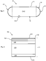
- FIG. 1 shows a tank 10 for storage of gaseous hydrogen at high pressure, for example 300 bar or more.
- the tank 10 comprises a cylindrical central section 12 and two hemispherical end portions 14, 16 formed by a boundary wall 11.
- a metal fitting 18 passing through the boundary wall 11 at hemispherical end portion 14 allows filling and emptying of the tank 10.
- Figure 2 shows the structure of a portion 100 of the boundary wall 11 of the tank 10 of Figure 1 , the structure of the boundary wall 11 being substantially the same at all positions around the wall 11.
- the boundary wall 11 has a laminate composite structure and has inner and outer surfaces 101, 103 respectively.
- the inner most layer 102 of the boundary wall is a resin-rich layer which provides a high-quality layer which remains substantially free of void and cracks under pressure and temperature cycling and which therefore provides a layer of low permeability for hydrogen stored within the tank 10.
- the resin-rich layer 102 provides the internal surface 101 of the boundary wall 11 and is supported on a glass-fibre composite layer 104.
- Glass fibres within layer 104 have a strain behaviour that is closer to the performance of the matrix surrounding the glass fibres than is the case for carbon fibres within carbon fibre composite material, so that incidence of fibre/matrix failure due to micro-cracking is lower for the layer 104 than would be the case for a carbon-fibre composite layer when the tank 10 is subjected to pressure cycling. Glass-fibre composite layer 104 therefore provides a higher degree of resistance to hydrogen leakage than would be the case for a carbon-fibre composite layer.
- Layers 106, 108 are carbon-fibre composite layers of relatively lower and higher ply thickness respectively. Layer 106 is thinner than layer 108. A low ply thickness layer gives a superior structural performance compared to a layer of high ply thickness but is more time-consuming to lay down. Layer 108 provides support for layers 106, 104, 102 and provides the boundary wall 11 with suitable stiffness and resistance to pressure loading when the tank 10 is filled with gaseous hydrogen. Layer 108 has a relatively high ply thickness compared to layer 106 and can therefore be laid down at a faster rate and with lower cost compared to layer 106. Layers 106, 108 can therefore be optimised to provide a required performance in terms of cost, speed of manufacture and hydrogen permeability performance.
- Layer 110 which provides the external surface 103 of the boundary wall, is an outer protective layer which may be a layer of elastomeric material or a layer of a glass-fibre composite material system.
- Toughening materials such as nano-clay, may optionally be encapsulated within one or more of the layers 102, 104, 106, 108, 110 to allow a reduction in the thickness of those layers and hence a reduction in the weight of tank 10.
- Membrane materials may be dispersed through the layers of boundary wall 11 to reduce or prevent permeation of hydrogen gas from the inner surface 101 to the outer surface 103 of the boundary wall 11 of the tank 10.
- the laminate boundary wall 11 provides micro-cracking resistance and hydrogen impermeability functionality towards the inner boundary 101 (layers 102,104, 106) and more structural, cheaper and faster deposition forms towards the outer boundary 103 (layers 108, 110).
- the tank 10 therefore has the required resistance to pressure cycling and hydrogen impermeability without having excessive weight and is therefore suitable for civil aviation applications.
Landscapes
- Engineering & Computer Science (AREA)
- Mechanical Engineering (AREA)
- General Engineering & Computer Science (AREA)
- Filling Or Discharging Of Gas Storage Vessels (AREA)
Abstract
Description
- The invention relates to storage tanks for storing gaseous hydrogen, particularly at high pressure for example at 300 bar or more.
- A laminate composite structure is a structure comprising a plurality of laminar layers at least one of which is of a composite material. A laminate composite gas storage tank is a gas storage tank in which the boundary wall of the tank has a laminate composite structure. Laminate composite gas storage tanks are currently used in automotive applications for storing gaseous hydrogen at high pressure. Motive power in these applications is typically provided by PEM fuel cells. Such tanks are also used in spaceflight applications and certain military drone applications for storage of gaseous hydrogen at high pressure.
- Laminate composite gas storage tanks for automotive applications are too heavy for civil aviation applications, in which significantly greater volumes of hydrogen are needed than in automotive applications. An automotive laminate composite gas storage tank typically comprises a polymer liner which contributes significantly to the tank's weight and therefore adversely affects its gravimetric efficiency. The weight and gravimetric efficiency of such a tank are also compromised by the requirement that the tank be resistant to micro-cracking within its boundary wall as a result of pressure cycling. Micro-cracking leads to leakage of stored gaseous hydrogen by permeation through the boundary wall of the tank. Providing resistance to micro-cracking tends to result in laminate composite structures of substantial thickness and weight. An automotive laminate composite gas storage tank typically has a gravimetric efficiency of around 6%. A laminate composite gas storage tank for a civil aircraft is required to have a gravimetric efficiency of around 10% in the case of short-range flight missions and more than 10% for longer range applications.
- In spacecraft applications, the rate of consumption of stored gaseous hydrogen is very high and greatly exceeds the rate at which gaseous hydrogen leaks from a storage tank by permeation. Lightweight laminate composite hydrogen storage tanks can therefore be produced for such applications with little or no concerns over hydrogen leakage. Furthermore, such tanks are typically used only once, or for a small number of cycles, and therefore do not need a significant degree of resistance to micro-cracking resulting from repeated pressure cycling. Although rapid consumption of gaseous hydrogen and a small number of pressure cycles allows for a lightweight tank within a spacecraft application, this design approach does not translate to civil aviation applications in which gaseous hydrogen is consumed at a much lower rate and in which a storage tank for gaseous hydrogen will experience many pressure and temperature cycles over its lifetime.
- A gaseous hydrogen storage tank for a civil aviation application is required to have a high gravimetric efficiency, low permeability to hydrogen and substantial resistance to micro-cracking caused by pressure cycling. Low hydrogen permeability is typically achieved at the expense of gravimetric efficiency.
- The present invention provides a storage tank for storing gaseous hydrogen, the storage tank comprising a boundary wall having a laminate composite structure which includes a resin-rich layer forming an internal surface of the boundary wall, a glass-fibre composite layer in contact with the resin-rich layer and a carbon fibre composite layer in contact with the glass-fibre composite layer on a side thereof remote from the resin-rich layer. The resin-rich layer provides a high degree of impermeability to gaseous hydrogen. The glass fibre composite layer is more resistant to micro-cracking than an equivalent thickness of carbon fibre composite since fibres within the layer are have a strain behaviour which is closer to that of the surrounding matrix than is the case for carbon fibre composite material. The carbon fibre composite layer provides the laminate composite structure with stiffness and support.
- The laminate composite structure may comprise a first carbon fibre composite layer in contact in contact with the glass fibre composite layer and a second carbon-fibre composite layer in contact with the first carbon fibre composite layer on a side thereof remote from the glass fibre composite layer, the ply thickness of the second carbon fibre composite layer being greater than the ply thickness of the first carbon fibre composite layer and the thickness of the second carbon fibre composite layer being greater than the thickness of the first carbon fibre composite layer. The first carbon fibre composite layer provides substantial resistance to micro-cracking. The second carbon fibre composite layer provides lower resistance to micro-cracking, but is less susceptible to such cracking because it is disposed on side of the first carbon fibre composite layer remote from the glass fibre composite layer which (together with the resin rich layer) is intended to contain pressurised hydrogen gas; the second carbon fibre composite layer can be laid down faster than the first, allowing faster and hence more cost effective fabrication of the overall structure.
- The laminate composite structure may further comprise a protective layer in contact with the second carbon fibre composite layer on a side thereof remote from the first carbon fibre layer. The protective layer may be a layer of elastomeric material or a layer of a glass fibre composite material system.
- The storage tank may comprise a toughening material encapsulated within one or more layers of the laminate composite structure and/or a membrane material within one or more layers of the laminate composite structure.
- Embodiments of the invention are described below by way of example only and with reference to the accompanying drawings in which:
- Figure 1
- shows a longitudinal section of a storage tank of the invention for storing gaseous hydrogen; and
- Figure 2
- shows the structure of a portion of the boundary wall of the
Figure 1 tank. -
Figure 1 shows atank 10 for storage of gaseous hydrogen at high pressure, for example 300 bar or more. Thetank 10 comprises a cylindricalcentral section 12 and twohemispherical end portions boundary wall 11. Ametal fitting 18 passing through theboundary wall 11 athemispherical end portion 14 allows filling and emptying of thetank 10. -
Figure 2 shows the structure of aportion 100 of theboundary wall 11 of thetank 10 ofFigure 1 , the structure of theboundary wall 11 being substantially the same at all positions around thewall 11. Theboundary wall 11 has a laminate composite structure and has inner andouter surfaces most layer 102 of the boundary wall is a resin-rich layer which provides a high-quality layer which remains substantially free of void and cracks under pressure and temperature cycling and which therefore provides a layer of low permeability for hydrogen stored within thetank 10. The resin-rich layer 102 provides theinternal surface 101 of theboundary wall 11 and is supported on a glass-fibre composite layer 104. Glass fibres withinlayer 104 have a strain behaviour that is closer to the performance of the matrix surrounding the glass fibres than is the case for carbon fibres within carbon fibre composite material, so that incidence of fibre/matrix failure due to micro-cracking is lower for thelayer 104 than would be the case for a carbon-fibre composite layer when thetank 10 is subjected to pressure cycling. Glass-fibre composite layer 104 therefore provides a higher degree of resistance to hydrogen leakage than would be the case for a carbon-fibre composite layer. -
Layers Layer 106 is thinner thanlayer 108. A low ply thickness layer gives a superior structural performance compared to a layer of high ply thickness but is more time-consuming to lay down.Layer 108 provides support forlayers boundary wall 11 with suitable stiffness and resistance to pressure loading when thetank 10 is filled with gaseous hydrogen.Layer 108 has a relatively high ply thickness compared tolayer 106 and can therefore be laid down at a faster rate and with lower cost compared tolayer 106.Layers -
Layer 110, which provides theexternal surface 103 of the boundary wall, is an outer protective layer which may be a layer of elastomeric material or a layer of a glass-fibre composite material system. - Toughening materials, such as nano-clay, may optionally be encapsulated within one or more of the
layers tank 10. - Membrane materials may be dispersed through the layers of
boundary wall 11 to reduce or prevent permeation of hydrogen gas from theinner surface 101 to theouter surface 103 of theboundary wall 11 of thetank 10. - The
laminate boundary wall 11 provides micro-cracking resistance and hydrogen impermeability functionality towards the inner boundary 101 (layers 102,104, 106) and more structural, cheaper and faster deposition forms towards the outer boundary 103 (layers 108, 110). Thetank 10 therefore has the required resistance to pressure cycling and hydrogen impermeability without having excessive weight and is therefore suitable for civil aviation applications.
Claims (6)
- A storage tank (10) for storing gaseous hydrogen, the gas storage tank comprising a boundary wall having a laminate composite structure (100) which includes a resin-rich layer (102) forming an internal surface (101) of the boundary wall, a glass-fibre composite layer (104) in contact with the resin-rich layer and a carbon fibre composite layer (106) in contact with the glass-fibre composite layer on a side thereof remote from the resin-rich layer.
- A storage tank according to claim 1 wherein the laminate composite structure comprises a first carbon fibre composite layer (106) in contact in contact with the glass fibre composite layer and a second carbon fibre composite layer (108) in contact with the first carbon fibre composite layer on a side thereof remote from the glass fibre composite layer, and wherein the ply thickness of the second carbon fibre composite layer is greater than the ply thickness of the first carbon fibre composite layer and the thickness of the second carbon fibre composite layer is greater than the thickness of the first carbon fibre composite layer.
- A storage tank according to claim 2 further wherein the laminate composite structure comprises a protective layer (110) in contact with the second carbon fibre composite layer on a side thereof remote from the first carbon fibre composite layer.
- A storage tank according to claim 3 wherein the protective layer is either a layer of elastomeric material or a layer of a glass fibre composite material system.
- A storage tank according to any preceding claim further comprising a toughening material encapsulated within one or more layers of the laminate composite structure.
- A storage tank according to any preceding claim further comprising a membrane material within one or more layers of the laminate composite structure.
Applications Claiming Priority (1)
| Application Number | Priority Date | Filing Date | Title |
|---|---|---|---|
| GBGB2016264.0A GB202016264D0 (en) | 2020-10-14 | 2020-10-14 | Laminate composite structure and gas storage tank comprising the same |
Publications (2)
| Publication Number | Publication Date |
|---|---|
| EP3984734A1 true EP3984734A1 (en) | 2022-04-20 |
| EP3984734B1 EP3984734B1 (en) | 2023-05-17 |
Family
ID=73460404
Family Applications (1)
| Application Number | Title | Priority Date | Filing Date |
|---|---|---|---|
| EP21196196.6A Active EP3984734B1 (en) | 2020-10-14 | 2021-09-13 | Storage tank for gaseous hydrogen |
Country Status (3)
| Country | Link |
|---|---|
| US (1) | US20220112984A1 (en) |
| EP (1) | EP3984734B1 (en) |
| GB (1) | GB202016264D0 (en) |
Cited By (3)
| Publication number | Priority date | Publication date | Assignee | Title |
|---|---|---|---|---|
| EP4600542A1 (en) | 2024-02-08 | 2025-08-13 | Prtc Nv | Storage container, method of manufacturing thereof, and use thereof |
| EP4600231A1 (en) | 2024-02-08 | 2025-08-13 | Prtc Nv | Insulation product, manufacturing method and system |
| WO2025233470A1 (en) | 2024-05-08 | 2025-11-13 | Prtc Nv | Method of manufacturing an insulated storage container |
Citations (3)
| Publication number | Priority date | Publication date | Assignee | Title |
|---|---|---|---|---|
| US20170104227A1 (en) * | 2015-10-08 | 2017-04-13 | Toyota Jidosha Kabushiki Kaisha | High-pressure tank |
| US20180066797A1 (en) * | 2016-09-05 | 2018-03-08 | Toyota Jidosha Kabushiki Kaisha | Fiber reinforced polymer matrix composite structure and high pressure container, and method of manufacturing the same |
| US20180163925A1 (en) * | 2016-12-08 | 2018-06-14 | Toyota Jidosha Kabushiki Kaisha | High-pressure tank |
-
2020
- 2020-10-14 GB GBGB2016264.0A patent/GB202016264D0/en not_active Ceased
-
2021
- 2021-09-13 EP EP21196196.6A patent/EP3984734B1/en active Active
- 2021-10-01 US US17/491,947 patent/US20220112984A1/en not_active Abandoned
Patent Citations (3)
| Publication number | Priority date | Publication date | Assignee | Title |
|---|---|---|---|---|
| US20170104227A1 (en) * | 2015-10-08 | 2017-04-13 | Toyota Jidosha Kabushiki Kaisha | High-pressure tank |
| US20180066797A1 (en) * | 2016-09-05 | 2018-03-08 | Toyota Jidosha Kabushiki Kaisha | Fiber reinforced polymer matrix composite structure and high pressure container, and method of manufacturing the same |
| US20180163925A1 (en) * | 2016-12-08 | 2018-06-14 | Toyota Jidosha Kabushiki Kaisha | High-pressure tank |
Cited By (3)
| Publication number | Priority date | Publication date | Assignee | Title |
|---|---|---|---|---|
| EP4600542A1 (en) | 2024-02-08 | 2025-08-13 | Prtc Nv | Storage container, method of manufacturing thereof, and use thereof |
| EP4600231A1 (en) | 2024-02-08 | 2025-08-13 | Prtc Nv | Insulation product, manufacturing method and system |
| WO2025233470A1 (en) | 2024-05-08 | 2025-11-13 | Prtc Nv | Method of manufacturing an insulated storage container |
Also Published As
| Publication number | Publication date |
|---|---|
| EP3984734B1 (en) | 2023-05-17 |
| GB202016264D0 (en) | 2020-11-25 |
| US20220112984A1 (en) | 2022-04-14 |
Similar Documents
| Publication | Publication Date | Title |
|---|---|---|
| EP3984734B1 (en) | Storage tank for gaseous hydrogen | |
| US11559964B2 (en) | Composite structures, composite storage tanks, vehicles including such composite storage tanks, and related systems and methods | |
| Mital et al. | Review of current state of the art and key design issues with potential solutions for liquid hydrogen cryogenic storage tank structures for aircraft applications | |
| US20080256960A1 (en) | Vehicles incorporating tanks for carrying cryogenic fluids and methods for forming such tanks | |
| Zheng et al. | The application of carbon fiber composites in cryotank | |
| KR20220118320A (en) | Liquid hydrogen storage container | |
| US10928005B2 (en) | Multicapillary system for storing fuel gases | |
| US20120205493A1 (en) | Common Bulkhead for Composite Propellant Tanks | |
| US20240116650A1 (en) | Aircraft with suspended hydrogen tank | |
| US20230272881A1 (en) | Device for storing cryogenic fluid and vehicle comprising such a device | |
| US11859765B2 (en) | Storage tank for liquid hydrogen | |
| JP2008032088A (en) | Tank | |
| EP3075524A1 (en) | Pressure bulkhead and method for producing a pressure bulkhead | |
| WO2015078565A1 (en) | Device for storing gas | |
| Sjöberg et al. | Liquid hydrogen tanks for low-emission aircraft | |
| EP4137736B1 (en) | High-pressure hydrogen storage tank made of carbon fiber composite material, and manufacturing process therefor | |
| KR20220117826A (en) | Liquid hydrogen storage container | |
| GB2610667A (en) | Pressure vessel, use and method of manufacture | |
| US12613012B2 (en) | Double-wall tank | |
| Kastell | Hydrogen storage technology for aerial vehicles | |
| EP4477558A1 (en) | An aircraft fuselage section | |
| KR20210087372A (en) | Liquefied natural gas tank adapted heat insulated structure technology, manufacturing method, and transport method of liquefied natural gas | |
| Arnold et al. | Spherical cryogenic hydrogen tank preliminary design trade studies | |
| Sippel et al. | Progress on advanced cryo-tanks structural design achieved in CHATT-project | |
| KR20220118321A (en) | Liquid hydrogen storage container |
Legal Events
| Date | Code | Title | Description |
|---|---|---|---|
| PUAI | Public reference made under article 153(3) epc to a published international application that has entered the european phase |
Free format text: ORIGINAL CODE: 0009012 |
|
| STAA | Information on the status of an ep patent application or granted ep patent |
Free format text: STATUS: THE APPLICATION HAS BEEN PUBLISHED |
|
| AK | Designated contracting states |
Kind code of ref document: A1 Designated state(s): AL AT BE BG CH CY CZ DE DK EE ES FI FR GB GR HR HU IE IS IT LI LT LU LV MC MK MT NL NO PL PT RO RS SE SI SK SM TR |
|
| STAA | Information on the status of an ep patent application or granted ep patent |
Free format text: STATUS: REQUEST FOR EXAMINATION WAS MADE |
|
| 17P | Request for examination filed |
Effective date: 20220708 |
|
| RBV | Designated contracting states (corrected) |
Designated state(s): AL AT BE BG CH CY CZ DE DK EE ES FI FR GB GR HR HU IE IS IT LI LT LU LV MC MK MT NL NO PL PT RO RS SE SI SK SM TR |
|
| GRAP | Despatch of communication of intention to grant a patent |
Free format text: ORIGINAL CODE: EPIDOSNIGR1 |
|
| STAA | Information on the status of an ep patent application or granted ep patent |
Free format text: STATUS: GRANT OF PATENT IS INTENDED |
|
| INTG | Intention to grant announced |
Effective date: 20230206 |
|
| GRAS | Grant fee paid |
Free format text: ORIGINAL CODE: EPIDOSNIGR3 |
|
| GRAA | (expected) grant |
Free format text: ORIGINAL CODE: 0009210 |
|
| STAA | Information on the status of an ep patent application or granted ep patent |
Free format text: STATUS: THE PATENT HAS BEEN GRANTED |
|
| AK | Designated contracting states |
Kind code of ref document: B1 Designated state(s): AL AT BE BG CH CY CZ DE DK EE ES FI FR GB GR HR HU IE IS IT LI LT LU LV MC MK MT NL NO PL PT RO RS SE SI SK SM TR |
|
| REG | Reference to a national code |
Ref country code: GB Ref legal event code: FG4D |
|
| REG | Reference to a national code |
Ref country code: DE Ref legal event code: R096 Ref document number: 602021002399 Country of ref document: DE |
|
| REG | Reference to a national code |
Ref country code: CH Ref legal event code: EP |
|
| REG | Reference to a national code |
Ref country code: IE Ref legal event code: FG4D |
|
| REG | Reference to a national code |
Ref country code: AT Ref legal event code: REF Ref document number: 1568245 Country of ref document: AT Kind code of ref document: T Effective date: 20230615 |
|
| P01 | Opt-out of the competence of the unified patent court (upc) registered |
Effective date: 20230528 |
|
| REG | Reference to a national code |
Ref country code: LT Ref legal event code: MG9D |
|
| REG | Reference to a national code |
Ref country code: NL Ref legal event code: MP Effective date: 20230517 |
|
| REG | Reference to a national code |
Ref country code: AT Ref legal event code: MK05 Ref document number: 1568245 Country of ref document: AT Kind code of ref document: T Effective date: 20230517 |
|
| PG25 | Lapsed in a contracting state [announced via postgrant information from national office to epo] |
Ref country code: SE Free format text: LAPSE BECAUSE OF FAILURE TO SUBMIT A TRANSLATION OF THE DESCRIPTION OR TO PAY THE FEE WITHIN THE PRESCRIBED TIME-LIMIT Effective date: 20230517 Ref country code: PT Free format text: LAPSE BECAUSE OF FAILURE TO SUBMIT A TRANSLATION OF THE DESCRIPTION OR TO PAY THE FEE WITHIN THE PRESCRIBED TIME-LIMIT Effective date: 20230918 Ref country code: NO Free format text: LAPSE BECAUSE OF FAILURE TO SUBMIT A TRANSLATION OF THE DESCRIPTION OR TO PAY THE FEE WITHIN THE PRESCRIBED TIME-LIMIT Effective date: 20230817 Ref country code: NL Free format text: LAPSE BECAUSE OF FAILURE TO SUBMIT A TRANSLATION OF THE DESCRIPTION OR TO PAY THE FEE WITHIN THE PRESCRIBED TIME-LIMIT Effective date: 20230517 Ref country code: ES Free format text: LAPSE BECAUSE OF FAILURE TO SUBMIT A TRANSLATION OF THE DESCRIPTION OR TO PAY THE FEE WITHIN THE PRESCRIBED TIME-LIMIT Effective date: 20230517 Ref country code: AT Free format text: LAPSE BECAUSE OF FAILURE TO SUBMIT A TRANSLATION OF THE DESCRIPTION OR TO PAY THE FEE WITHIN THE PRESCRIBED TIME-LIMIT Effective date: 20230517 |
|
| REG | Reference to a national code |
Ref country code: DE Ref legal event code: R079 Ref document number: 602021002399 Country of ref document: DE Free format text: PREVIOUS MAIN CLASS: B32B0001020000 Ipc: B32B0001000000 |
|
| PG25 | Lapsed in a contracting state [announced via postgrant information from national office to epo] |
Ref country code: RS Free format text: LAPSE BECAUSE OF FAILURE TO SUBMIT A TRANSLATION OF THE DESCRIPTION OR TO PAY THE FEE WITHIN THE PRESCRIBED TIME-LIMIT Effective date: 20230517 Ref country code: PL Free format text: LAPSE BECAUSE OF FAILURE TO SUBMIT A TRANSLATION OF THE DESCRIPTION OR TO PAY THE FEE WITHIN THE PRESCRIBED TIME-LIMIT Effective date: 20230517 Ref country code: LV Free format text: LAPSE BECAUSE OF FAILURE TO SUBMIT A TRANSLATION OF THE DESCRIPTION OR TO PAY THE FEE WITHIN THE PRESCRIBED TIME-LIMIT Effective date: 20230517 Ref country code: LT Free format text: LAPSE BECAUSE OF FAILURE TO SUBMIT A TRANSLATION OF THE DESCRIPTION OR TO PAY THE FEE WITHIN THE PRESCRIBED TIME-LIMIT Effective date: 20230517 Ref country code: IS Free format text: LAPSE BECAUSE OF FAILURE TO SUBMIT A TRANSLATION OF THE DESCRIPTION OR TO PAY THE FEE WITHIN THE PRESCRIBED TIME-LIMIT Effective date: 20230917 Ref country code: HR Free format text: LAPSE BECAUSE OF FAILURE TO SUBMIT A TRANSLATION OF THE DESCRIPTION OR TO PAY THE FEE WITHIN THE PRESCRIBED TIME-LIMIT Effective date: 20230517 Ref country code: GR Free format text: LAPSE BECAUSE OF FAILURE TO SUBMIT A TRANSLATION OF THE DESCRIPTION OR TO PAY THE FEE WITHIN THE PRESCRIBED TIME-LIMIT Effective date: 20230818 |
|
| PG25 | Lapsed in a contracting state [announced via postgrant information from national office to epo] |
Ref country code: FI Free format text: LAPSE BECAUSE OF FAILURE TO SUBMIT A TRANSLATION OF THE DESCRIPTION OR TO PAY THE FEE WITHIN THE PRESCRIBED TIME-LIMIT Effective date: 20230517 |
|
| PG25 | Lapsed in a contracting state [announced via postgrant information from national office to epo] |
Ref country code: SK Free format text: LAPSE BECAUSE OF FAILURE TO SUBMIT A TRANSLATION OF THE DESCRIPTION OR TO PAY THE FEE WITHIN THE PRESCRIBED TIME-LIMIT Effective date: 20230517 |
|
| PG25 | Lapsed in a contracting state [announced via postgrant information from national office to epo] |
Ref country code: SM Free format text: LAPSE BECAUSE OF FAILURE TO SUBMIT A TRANSLATION OF THE DESCRIPTION OR TO PAY THE FEE WITHIN THE PRESCRIBED TIME-LIMIT Effective date: 20230517 Ref country code: SK Free format text: LAPSE BECAUSE OF FAILURE TO SUBMIT A TRANSLATION OF THE DESCRIPTION OR TO PAY THE FEE WITHIN THE PRESCRIBED TIME-LIMIT Effective date: 20230517 Ref country code: RO Free format text: LAPSE BECAUSE OF FAILURE TO SUBMIT A TRANSLATION OF THE DESCRIPTION OR TO PAY THE FEE WITHIN THE PRESCRIBED TIME-LIMIT Effective date: 20230517 Ref country code: EE Free format text: LAPSE BECAUSE OF FAILURE TO SUBMIT A TRANSLATION OF THE DESCRIPTION OR TO PAY THE FEE WITHIN THE PRESCRIBED TIME-LIMIT Effective date: 20230517 Ref country code: DK Free format text: LAPSE BECAUSE OF FAILURE TO SUBMIT A TRANSLATION OF THE DESCRIPTION OR TO PAY THE FEE WITHIN THE PRESCRIBED TIME-LIMIT Effective date: 20230517 Ref country code: CZ Free format text: LAPSE BECAUSE OF FAILURE TO SUBMIT A TRANSLATION OF THE DESCRIPTION OR TO PAY THE FEE WITHIN THE PRESCRIBED TIME-LIMIT Effective date: 20230517 |
|
| REG | Reference to a national code |
Ref country code: DE Ref legal event code: R097 Ref document number: 602021002399 Country of ref document: DE |
|
| PLBE | No opposition filed within time limit |
Free format text: ORIGINAL CODE: 0009261 |
|
| STAA | Information on the status of an ep patent application or granted ep patent |
Free format text: STATUS: NO OPPOSITION FILED WITHIN TIME LIMIT |
|
| 26N | No opposition filed |
Effective date: 20240220 |
|
| PG25 | Lapsed in a contracting state [announced via postgrant information from national office to epo] |
Ref country code: SI Free format text: LAPSE BECAUSE OF FAILURE TO SUBMIT A TRANSLATION OF THE DESCRIPTION OR TO PAY THE FEE WITHIN THE PRESCRIBED TIME-LIMIT Effective date: 20230517 |
|
| PG25 | Lapsed in a contracting state [announced via postgrant information from national office to epo] |
Ref country code: LU Free format text: LAPSE BECAUSE OF NON-PAYMENT OF DUE FEES Effective date: 20230913 |
|
| REG | Reference to a national code |
Ref country code: BE Ref legal event code: MM Effective date: 20230930 |
|
| PG25 | Lapsed in a contracting state [announced via postgrant information from national office to epo] |
Ref country code: SI Free format text: LAPSE BECAUSE OF FAILURE TO SUBMIT A TRANSLATION OF THE DESCRIPTION OR TO PAY THE FEE WITHIN THE PRESCRIBED TIME-LIMIT Effective date: 20230517 Ref country code: IT Free format text: LAPSE BECAUSE OF FAILURE TO SUBMIT A TRANSLATION OF THE DESCRIPTION OR TO PAY THE FEE WITHIN THE PRESCRIBED TIME-LIMIT Effective date: 20230517 Ref country code: LU Free format text: LAPSE BECAUSE OF NON-PAYMENT OF DUE FEES Effective date: 20230913 Ref country code: MC Free format text: LAPSE BECAUSE OF FAILURE TO SUBMIT A TRANSLATION OF THE DESCRIPTION OR TO PAY THE FEE WITHIN THE PRESCRIBED TIME-LIMIT Effective date: 20230517 |
|
| REG | Reference to a national code |
Ref country code: IE Ref legal event code: MM4A |
|
| PG25 | Lapsed in a contracting state [announced via postgrant information from national office to epo] |
Ref country code: IE Free format text: LAPSE BECAUSE OF NON-PAYMENT OF DUE FEES Effective date: 20230913 |
|
| PG25 | Lapsed in a contracting state [announced via postgrant information from national office to epo] |
Ref country code: IE Free format text: LAPSE BECAUSE OF NON-PAYMENT OF DUE FEES Effective date: 20230913 |
|
| PG25 | Lapsed in a contracting state [announced via postgrant information from national office to epo] |
Ref country code: BE Free format text: LAPSE BECAUSE OF NON-PAYMENT OF DUE FEES Effective date: 20230930 |
|
| PG25 | Lapsed in a contracting state [announced via postgrant information from national office to epo] |
Ref country code: BG Free format text: LAPSE BECAUSE OF FAILURE TO SUBMIT A TRANSLATION OF THE DESCRIPTION OR TO PAY THE FEE WITHIN THE PRESCRIBED TIME-LIMIT Effective date: 20230517 |
|
| PG25 | Lapsed in a contracting state [announced via postgrant information from national office to epo] |
Ref country code: BG Free format text: LAPSE BECAUSE OF FAILURE TO SUBMIT A TRANSLATION OF THE DESCRIPTION OR TO PAY THE FEE WITHIN THE PRESCRIBED TIME-LIMIT Effective date: 20230517 |
|
| REG | Reference to a national code |
Ref country code: CH Ref legal event code: PL |
|
| PG25 | Lapsed in a contracting state [announced via postgrant information from national office to epo] |
Ref country code: CH Free format text: LAPSE BECAUSE OF NON-PAYMENT OF DUE FEES Effective date: 20240930 |
|
| PG25 | Lapsed in a contracting state [announced via postgrant information from national office to epo] |
Ref country code: CY Free format text: LAPSE BECAUSE OF FAILURE TO SUBMIT A TRANSLATION OF THE DESCRIPTION OR TO PAY THE FEE WITHIN THE PRESCRIBED TIME-LIMIT; INVALID AB INITIO Effective date: 20210913 |
|
| PG25 | Lapsed in a contracting state [announced via postgrant information from national office to epo] |
Ref country code: HU Free format text: LAPSE BECAUSE OF FAILURE TO SUBMIT A TRANSLATION OF THE DESCRIPTION OR TO PAY THE FEE WITHIN THE PRESCRIBED TIME-LIMIT; INVALID AB INITIO Effective date: 20210913 |
|
| PGFP | Annual fee paid to national office [announced via postgrant information from national office to epo] |
Ref country code: DE Payment date: 20250926 Year of fee payment: 5 |
|
| PGFP | Annual fee paid to national office [announced via postgrant information from national office to epo] |
Ref country code: GB Payment date: 20250923 Year of fee payment: 5 |
|
| PGFP | Annual fee paid to national office [announced via postgrant information from national office to epo] |
Ref country code: FR Payment date: 20250925 Year of fee payment: 5 |
|
| PG25 | Lapsed in a contracting state [announced via postgrant information from national office to epo] |
Ref country code: TR Free format text: LAPSE BECAUSE OF FAILURE TO SUBMIT A TRANSLATION OF THE DESCRIPTION OR TO PAY THE FEE WITHIN THE PRESCRIBED TIME-LIMIT Effective date: 20230517 |