EP3984637A1 - Laboratory system particularly for use in microscopy - Google Patents
Laboratory system particularly for use in microscopy Download PDFInfo
- Publication number
- EP3984637A1 EP3984637A1 EP21171853.1A EP21171853A EP3984637A1 EP 3984637 A1 EP3984637 A1 EP 3984637A1 EP 21171853 A EP21171853 A EP 21171853A EP 3984637 A1 EP3984637 A1 EP 3984637A1
- Authority
- EP
- European Patent Office
- Prior art keywords
- laboratory
- fluid
- bench
- microscope
- incubation
- Prior art date
- Legal status (The legal status is an assumption and is not a legal conclusion. Google has not performed a legal analysis and makes no representation as to the accuracy of the status listed.)
- Granted
Links
Images




Classifications
-
- G—PHYSICS
- G02—OPTICS
- G02B—OPTICAL ELEMENTS, SYSTEMS OR APPARATUS
- G02B21/00—Microscopes
- G02B21/33—Immersion oils, or microscope systems or objectives for use with immersion fluids
-
- G—PHYSICS
- G01—MEASURING; TESTING
- G01N—INVESTIGATING OR ANALYSING MATERIALS BY DETERMINING THEIR CHEMICAL OR PHYSICAL PROPERTIES
- G01N1/00—Sampling; Preparing specimens for investigation
- G01N1/02—Devices for withdrawing samples
- G01N1/10—Devices for withdrawing samples in the liquid or fluent state
- G01N1/14—Suction devices, e.g. pumps; Ejector devices
-
- B—PERFORMING OPERATIONS; TRANSPORTING
- B01—PHYSICAL OR CHEMICAL PROCESSES OR APPARATUS IN GENERAL
- B01L—CHEMICAL OR PHYSICAL LABORATORY APPARATUS FOR GENERAL USE
- B01L1/00—Enclosures; Chambers
- B01L1/02—Air-pressure chambers; Air-locks therefor
- B01L1/025—Environmental chambers
-
- B—PERFORMING OPERATIONS; TRANSPORTING
- B01—PHYSICAL OR CHEMICAL PROCESSES OR APPARATUS IN GENERAL
- B01L—CHEMICAL OR PHYSICAL LABORATORY APPARATUS FOR GENERAL USE
- B01L3/00—Containers or dishes for laboratory use, e.g. laboratory glassware; Droppers
- B01L3/52—Containers specially adapted for storing or dispensing a reagent
-
- B—PERFORMING OPERATIONS; TRANSPORTING
- B01—PHYSICAL OR CHEMICAL PROCESSES OR APPARATUS IN GENERAL
- B01L—CHEMICAL OR PHYSICAL LABORATORY APPARATUS FOR GENERAL USE
- B01L9/00—Supporting devices; Holding devices
- B01L9/02—Laboratory benches or tables; Fittings therefor
-
- G—PHYSICS
- G02—OPTICS
- G02B—OPTICAL ELEMENTS, SYSTEMS OR APPARATUS
- G02B21/00—Microscopes
- G02B21/24—Base structure
- G02B21/26—Stages; Adjusting means therefor
-
- B—PERFORMING OPERATIONS; TRANSPORTING
- B01—PHYSICAL OR CHEMICAL PROCESSES OR APPARATUS IN GENERAL
- B01L—CHEMICAL OR PHYSICAL LABORATORY APPARATUS FOR GENERAL USE
- B01L2300/00—Additional constructional details
- B01L2300/18—Means for temperature control
-
- B—PERFORMING OPERATIONS; TRANSPORTING
- B01—PHYSICAL OR CHEMICAL PROCESSES OR APPARATUS IN GENERAL
- B01L—CHEMICAL OR PHYSICAL LABORATORY APPARATUS FOR GENERAL USE
- B01L2400/00—Moving or stopping fluids
- B01L2400/04—Moving fluids with specific forces or mechanical means
- B01L2400/0475—Moving fluids with specific forces or mechanical means specific mechanical means and fluid pressure
- B01L2400/0487—Moving fluids with specific forces or mechanical means specific mechanical means and fluid pressure fluid pressure, pneumatics
-
- G—PHYSICS
- G01—MEASURING; TESTING
- G01N—INVESTIGATING OR ANALYSING MATERIALS BY DETERMINING THEIR CHEMICAL OR PHYSICAL PROPERTIES
- G01N1/00—Sampling; Preparing specimens for investigation
- G01N2001/002—Devices for supplying or distributing samples to an analysing apparatus
-
- G—PHYSICS
- G01—MEASURING; TESTING
- G01N—INVESTIGATING OR ANALYSING MATERIALS BY DETERMINING THEIR CHEMICAL OR PHYSICAL PROPERTIES
- G01N1/00—Sampling; Preparing specimens for investigation
- G01N1/02—Devices for withdrawing samples
- G01N1/10—Devices for withdrawing samples in the liquid or fluent state
- G01N2001/1062—Sampling under constant temperature, pressure, or the like
Definitions
- the present inventive concept relates generally to laboratory systems comprising a laboratory device which needs to be supplied with a fluid, particularly a liquid, and/or wherein a fluid, particularly a liquid, needs to be disposed of.
- the laboratory system may comprise a microscope having an immersion system for supplying and/or disposing of an immersion liquid, and/or using an incubation system for supplying and/or disposing of a fluid, particularly a gas and/or a liquid being a component of an incubation atmosphere in a sample chamber of the microscope.
- Laboratory devices having e.g. a climate chamber are known, which climate chamber needs to be supplied with one or more fluids, particularly liquids, taken from a fluid reservoir, while used or worn fluid needs to be conducted back to another fluid reservoir.
- fluid reservoirs are typically placed next to the laboratory device and thus waste valuable space which could otherwise be used as workspace in the laboratory.
- the tubes and hoses necessary for transporting the fluids tend to obstruct the workspace and are likely to be damaged or kinked.
- An example of such a laboratory device includes a microscope comprising a climate chamber which itself forms or comprises a sample chamber for examining samples, particularly living samples like cells.
- the microscope may be connected to an incubation system.
- the incubation system provides an incubation atmosphere of a predetermined composition and/or of a predetermined temperature.
- the CO 2 -content, the humidity and the temperature of the incubation atmosphere are controlled.
- gasses and/or liquids have to be supplied to the incubation system.
- Immersion liquids are typically water- or oil-based.
- water is usually drained from a water reservoir located somewhere inside or outside the microscope.
- immersion microscopes having an incubated sample chamber are used.
- the present inventive concept provides an improved laboratory system of claim 1, comprising a laboratory device placed on a table surface of a laboratory bench, the laboratory bench having at least one receiving section below the table surface of the laboratory bench, which receiving section is adapted to receive at least one fluid reservoir which is connected to the laboratory device.
- the at least one fluid reservoir does no longer need to be placed next to or into the laboratory device but can be "stowed away" below the table surface by putting it into the at least one receiving section adapted to receive one or more fluid reservoirs.
- valuable workspace which was formally absorbed by fluid reservoirs can now be freely used by an operator of the laboratory device.
- the one or more receiving sections are part of the laboratory bench beneath the laboratory device, the footprint of the laboratory system is minimized.
- an existing laboratory bench can be retrofitted to have the necessary one or more receiving sections for accommodating the at least one fluid reservoir.
- the present inventive concept further allows a faster and safer operation of the laboratory device as the storage locations of the fluid reservoirs are predetermined, the fluid reservoirs in the receiving sections are protected from possible damage, tilting and falling over, the tubes and hoses can effectively be protected from damage or kinking, thus fulfilling work safety requirements.
- the laboratory device comprises a climate chamber and/or an incubation system. Examples of a climate chamber and of an incubation system are discussed above in connection with a microscope used as at least a part of a laboratory device.
- the laboratory system further comprises a first fluid supply system that supplies at least one fluid to the climate chamber and/or the incubation system, the fluid supply system being connected to the at least one fluid reservoir in which said at least one fluid is storable.
- the climate camber may be an integrated climate chamber integrated into the microscope.
- the climate chamber may form or comprise a sample chamber of the microscope (incubated sample chamber) or form a small chamber including a microenvironment around most of the topside of the sample itself (stagetop incubator).
- the microscope is connected to the incubation system.
- the incubation system provides an incubation atmosphere of a predetermined composition and/or of a predetermined temperature. Typically, the CO 2 -content, the humidity and the temperature of the incubation atmosphere are controlled.
- gasses and/or liquids have to be supplied to the incubation system and/or to the climate chamber itself.
- the first fluid supply system comprises one or more fluid pumps and tubes for conducting a fluid (which is a liquid and/or a gas) to the climate chamber and/or to the incubation system.
- a fluid which is a liquid and/or a gas
- examples of such fluids are water, carbon dioxide or nitrogen.
- Water is typically used to generate an incubation atmosphere of predefined humidity.
- Carbon dioxide or nitrogen serve the purpose of adjusting the CO 2 content of the atmosphere.
- the fluid supply system is connected to the fluid reservoir or to each of the fluid reservoirs for supplying the fluid(s) to the climate chamber and/or to the incubation system.
- the first fluid supply system is advantageously, as far as possible, integrated into the laboratory device and/or the laboratory bench. Examples will be discussed further below, also in connection with the figures.
- the first fluid supply system may comprise one or more feedthroughs for said tubes/hoses (the term “hose” can be regarded interchangeable with “tube”).
- feedthroughs help integrate the tubes into the laboratory device and/or laboratory bench, thus avoiding an external laying of flexible tubes and hoses outside of the laboratory bench and/or the laboratory device.
- said at least one fluid pump is arranged at or in the laboratory bench, at or in the incubation system, at or in the laboratory device, and/or at or in the climate chamber. This also helps minimize the footprint of the system.
- the laboratory device comprises a microscope with at least one immersion objective
- the laboratory system further comprises a second fluid supply system that supplies an immersion fluid to the immersion objective, the second fluid supply system being connected to the at least one fluid reservoir in which said immersion fluid is storable.
- Immersion fluid typically is an immersion liquid which is supplied from an immersion liquid reservoir to the front lens of the microscope objective.
- Immersion liquids are typically water- or oil-based.
- immersion microscopes having a climate chamber are used for inspection of living cells (see embodiment described above).
- liquids are considered as an example of the general term "fluid” unless otherwise specified.
- the second fluid/liquid supply system typically comprising one or more fluid pumps and tubes for conducting the immersion liquid(s), supplies one or more immersion liquids to the immersion objective.
- the second fluid/liquid supply system is advantageously, as far as possible, integrated into the laboratory device and/or the laboratory bench. Examples will be discussed further below, also in connection with the figures.
- the second fluid supply system may comprise one or more feedthroughs for said tubes/hoses (the term “hose” can be regarded interchangeable with “tube”).
- feedthroughs help integrate the tubes into the laboratory device and/or laboratory bench, thus avoiding an external laying of flexible tubes and hoses outside of the laboratory bench and/or the laboratory device.
- said at least one fluid pump is arranged at or in the laboratory bench and/or at or in the laboratory device/microscope. This also helps minimize the footprint of the system.
- the at least one receiving section comprises at least one of one or more receptacle compartments, one or more name tags, and one or more retainer portions.
- the receptacle compartment is adapted to receive a fluid reservoir, it may also be advantageous if a receptacle compartment is adapted to receive two or more fluid reservoirs.
- Name tags can be used to indicate the kind of fluid(s)/liquid(s) which is or are stored in the respective receptacle compartment
- a retainer portion is suitable to avoid tilting and particularly dropping out of a fluid/liquid reservoir out of the receptacle compartment.
- the at least one receiving section of the laboratory system may particularly be in the form of a rack which is integrated into the laboratory bench.
- the at least one receiving section may also be integrated into one or more bench legs or form at least a part of one or more bench legs of the laboratory bench. Again, these embodiments help minimize the footprint of the system and allow a compact design of the laboratory system.
- the liquid supply system preferably comprises at least one feedthrough which is arranged in adjacent sections of the laboratory bench and the laboratory device.
- a feedthrough allows an optimal connection of the laboratory device with a fluid reservoir minimizing tube lengths and avoiding external tube laying.
- a preferred embodiment of the laboratory device is a microscope.
- the microscope preferably comprises a climate chamber which comprises or represents a sample chamber for accommodating a sample to be examined by the microscope.
- the microscope may be connected to an incubation system, which is then another part of the laboratory device, for providing incubation atmosphere into the sample chamber/climate chamber of the microscope.
- the microscope itself comprises an (integrated) incubation system.
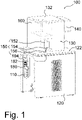
- Figure 1 schematically shows an embodiment of the present inventive concept in a perspective view from the right, the laboratory system 100 comprising a laboratory device 130 placed on a table surface 122 of a laboratory bench 120.
- the laboratory bench 120 comprises a receiving section 180 adapted to receive one liquid reservoir 110 which is connected to the laboratory device 130 for supplying liquid to the laboratory device 130 and/or for disposing of a liquid from the laboratory device 130.
- the laboratory device 130 comprises a microscope 132 and an incubation system 140 for producing an incubation atmosphere inside the climate chamber 160 of the microscope 132.
- the microscope 132 is connected to the incubation system 140.
- the incubation system 140 provides an incubation atmosphere of a predetermined CO 2 -content, a predefined humidity and temperature into the climate chamber 160 of the microscope 132.
- the incubation system 140 and/or the climate chamber 160 have to be supplied with a fluid, particularly a liquid and/or a gas.
- the microscope 132 of Figure 1 is configured as an immersion microscope having an immersion objective (not shown).
- the immersion objective is part of an inverted microscope and thus located beneath the sample to be examined, i.e. below the climate chamber 160.
- the liquid reservoir 110 is a bottle storing an incubation liquid, i.e. a liquid used for generating an incubation atmosphere, particularly water.
- Bottle 110 as shown in Figure 1 is placed in a receptacle compartment 182 and is connected to a flexible tube 194.
- This tube 194 is laid beneath the table top of the laboratory bench 120 and from there led to the incubation system 140 (see Figure 2 ).
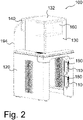
- the bottles 110 shown in Figure 2 are placed in corresponding receiving sections 180 and connected to tubes 154, which are led through one or more feedthroughs 156 to the liquid pump 152 as shown in Figure 1 .
- Liquid pump 152, feedthroughs 156 and tubes 154 together form a second/immersion liquid supply system 150 as designated in Figure 1 .
- the liquid pump 152 supplies immersion liquid to the immersion objective of the microscope 132.
- bottle 110 as shown in Figure 1 is connected via a flexible tube/hose 194 as also shown in Figure 2 with the incubation system 140.
- the two bottles 110 shown in Figure 2 are connected with fluid pump 152 via tubes 154 shown in Figure 1 .
- the tube lengths can be kept as short as possible.
- also different connections may be reasonable depending on the specific application.
- the receiving sections 180 are built in racks which are integrated into two bench legs, opposite one another, of the laboratory bench 120. This results in a laboratory system 100 of a very small footprint, the little and thus valuable workspace is not absorbed by fluid reservoirs, and the tubes 154, 194 are protected from damage and kinking such that work safety requirements can be fulfilled.
- Pump 152 is arranged at the laboratory device 130, more exactly, in a recess of the laboratory device 130 or microscope 132.
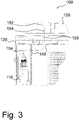
- Figure 3 shows the tube layout of the one or more tubes 154 to the liquid pump 152 in more detail.
- Tube 154 is led from the bottle 110 through a number of feedthroughs 156 in order to exit the laboratory bench 120 underneath the laboratory device 130.
- This tube layout ensures that tube 154 does not obstruct the workspace of the laboratory system and is not damaged or kinked.
- FIG 4 shows another detailed view on two bottles 110 placed in respective receiving sections 180, one on top of the other.
- each receiving section 180 comprises a receptacle compartment 182, a name tag 484 and a retainer portion 486.
- the name tags indicate whether the liquid in the bottle 110 is "fresh" or "waste”.
- the retainer portions 486 ensure that the bottles 110 are stored safely and that tilting or dropping out of a bottle 110 out of the compartment 182 is avoided.
- each bottle 110 has an indicator of the fluid level.
- Figures 5 and 6 show another embodiment of a laboratory system 100 comprising a laboratory device 130, the laboratory device 130 comprising a climate chamber 160 and an incubation system 140.
- the laboratory device 130 is placed on a table surface 122 of a laboratory bench 120.
- Figures 5 and 6 illustrate in more detail a possible implementation of a first fluid supply system 190 for supplying at least one fluid to the climate chamber 160 and/or the incubation system 140.
- a fluid reservoir/bottle 110 is connected via a flexible tube 194 and a fluid pump 192 to the incubation system 140.
- a number of feedthroughs 196 is provided inside the laboratory bench 120 in order to avoid a tube laying outside of the laboratory bench 120 and in order to keep the tube lengths as short as possible.
- Pump 192 is arranged below the table top of the laboratory bench 120 and is configured to drain a liquid/water from bottle 110 and conduct it to the incubation system 140.
- water is used as the liquid such that the incubation system 140 is able to control a predetermined humidity inside the climate chamber 160.
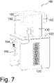
- Figures 7 and 8 show yet another embodiment of a laboratory system 100 similar to that of Figures 5 and 6 .
- the pump 192 for pumping an incubation fluid like water from bottle 110 is arranged inside the climate chamber 160.
- the feed tube 192 passes through the inside of the laboratory bench 120 and further through the table surface 122 of the laboratory bench 120 and inside the laboratory device 130 or microscope 132 into the climate chamber 160.
- the corresponding feedthroughs are not shown in Figures 7 and 8 .
- the incubation fluid pump 192 can further include or be connected to a vaporizer for supplying water vapour into the climate chamber 160. Alternatively, the pump 192 may be integrated into the incubation system 140.
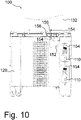
- Figures 9 and 10 show another embodiment of a laboratory system 100 with an alternative arrangement of a pump 152 of the second fluid supply system 150.
- the immersion liquid pump 152 in this embodiment is arranged at the laboratory bench 120 beneath the table top of the laboratory bench 120 next to the bottles 110.
- the feed tube 154 from the upper bottle 110 provides fresh water/immersion liquid through the pump 152 and through the further tube 154 inside the microscope 132 to an immersion objective of the microscope 132. Waste water/immersion liquid is returned to the lower bottle 110. Again, feedthroughs are depicted 156.
Landscapes
- Chemical & Material Sciences (AREA)
- Health & Medical Sciences (AREA)
- Physics & Mathematics (AREA)
- Clinical Laboratory Science (AREA)
- Chemical Kinetics & Catalysis (AREA)
- Analytical Chemistry (AREA)
- General Physics & Mathematics (AREA)
- Life Sciences & Earth Sciences (AREA)
- Optics & Photonics (AREA)
- Hydrology & Water Resources (AREA)
- Biochemistry (AREA)
- General Health & Medical Sciences (AREA)
- Immunology (AREA)
- Pathology (AREA)
- Medicinal Chemistry (AREA)
- Oil, Petroleum & Natural Gas (AREA)
- Apparatus Associated With Microorganisms And Enzymes (AREA)
- Microscoopes, Condenser (AREA)
- Devices For Use In Laboratory Experiments (AREA)
Abstract
Description
- The present inventive concept relates generally to laboratory systems comprising a laboratory device which needs to be supplied with a fluid, particularly a liquid, and/or wherein a fluid, particularly a liquid, needs to be disposed of. More particularly, the laboratory system may comprise a microscope having an immersion system for supplying and/or disposing of an immersion liquid, and/or using an incubation system for supplying and/or disposing of a fluid, particularly a gas and/or a liquid being a component of an incubation atmosphere in a sample chamber of the microscope.
- Laboratory devices having e.g. a climate chamber are known, which climate chamber needs to be supplied with one or more fluids, particularly liquids, taken from a fluid reservoir, while used or worn fluid needs to be conducted back to another fluid reservoir. Such fluid reservoirs are typically placed next to the laboratory device and thus waste valuable space which could otherwise be used as workspace in the laboratory. Also, the tubes and hoses necessary for transporting the fluids tend to obstruct the workspace and are likely to be damaged or kinked.
- An example of such a laboratory device, without loss of generality, includes a microscope comprising a climate chamber which itself forms or comprises a sample chamber for examining samples, particularly living samples like cells. In order to generate an incubation atmosphere in the sample chamber, the microscope may be connected to an incubation system. The incubation system provides an incubation atmosphere of a predetermined composition and/or of a predetermined temperature. Typically the CO2-content, the humidity and the temperature of the incubation atmosphere are controlled. To this end, gasses and/or liquids have to be supplied to the incubation system.
- Other examples relate to microscopes used for immersion microscopy where immersion liquid is supplied from a reservoir to the front lens of a microscope objective. Immersion liquids are typically water- or oil-based. For immersion with e.g. water objectives, water is usually drained from a water reservoir located somewhere inside or outside the microscope. Often, immersion microscopes having an incubated sample chamber are used.
- From the above described situation a need of an improved handling of such laboratory devices arouse. Particularly, safety requirements in a laboratory using such laboratory devices have to be fulfilled.
- The present inventive concept provides an improved laboratory system of
claim 1, comprising a laboratory device placed on a table surface of a laboratory bench, the laboratory bench having at least one receiving section below the table surface of the laboratory bench, which receiving section is adapted to receive at least one fluid reservoir which is connected to the laboratory device. According to the present inventive concept, the at least one fluid reservoir does no longer need to be placed next to or into the laboratory device but can be "stowed away" below the table surface by putting it into the at least one receiving section adapted to receive one or more fluid reservoirs. Thus, valuable workspace which was formally absorbed by fluid reservoirs can now be freely used by an operator of the laboratory device. As the one or more receiving sections are part of the laboratory bench beneath the laboratory device, the footprint of the laboratory system is minimized. Further, an existing laboratory bench can be retrofitted to have the necessary one or more receiving sections for accommodating the at least one fluid reservoir. - The present inventive concept further allows a faster and safer operation of the laboratory device as the storage locations of the fluid reservoirs are predetermined, the fluid reservoirs in the receiving sections are protected from possible damage, tilting and falling over, the tubes and hoses can effectively be protected from damage or kinking, thus fulfilling work safety requirements.
- Further advantages and embodiments of the present inventive concept are discussed in the following.
- In a preferred embodiment, the laboratory device comprises a climate chamber and/or an incubation system. Examples of a climate chamber and of an incubation system are discussed above in connection with a microscope used as at least a part of a laboratory device. In this embodiment, the laboratory system further comprises a first fluid supply system that supplies at least one fluid to the climate chamber and/or the incubation system, the fluid supply system being connected to the at least one fluid reservoir in which said at least one fluid is storable. For instance, if the laboratory system comprises a microscope and an incubation system, the climate camber may be an integrated climate chamber integrated into the microscope. The climate chamber may form or comprise a sample chamber of the microscope (incubated sample chamber) or form a small chamber including a microenvironment around most of the topside of the sample itself (stagetop incubator). In order to generate an incubation atmosphere in the climate chamber, the microscope is connected to the incubation system. The incubation system provides an incubation atmosphere of a predetermined composition and/or of a predetermined temperature. Typically, the CO2-content, the humidity and the temperature of the incubation atmosphere are controlled. To this end, gasses and/or liquids have to be supplied to the incubation system and/or to the climate chamber itself.
- Preferably, the first fluid supply system comprises one or more fluid pumps and tubes for conducting a fluid (which is a liquid and/or a gas) to the climate chamber and/or to the incubation system. Examples of such fluids are water, carbon dioxide or nitrogen. Water is typically used to generate an incubation atmosphere of predefined humidity. Carbon dioxide or nitrogen serve the purpose of adjusting the CO2 content of the atmosphere. The fluid supply system is connected to the fluid reservoir or to each of the fluid reservoirs for supplying the fluid(s) to the climate chamber and/or to the incubation system. In order to minimize the footprint of the laboratory system, the first fluid supply system is advantageously, as far as possible, integrated into the laboratory device and/or the laboratory bench. Examples will be discussed further below, also in connection with the figures.
- Apart from one or more fluid/liquid pumps and tubes/hoses, the first fluid supply system may comprise one or more feedthroughs for said tubes/hoses (the term "hose" can be regarded interchangeable with "tube"). Such feedthroughs help integrate the tubes into the laboratory device and/or laboratory bench, thus avoiding an external laying of flexible tubes and hoses outside of the laboratory bench and/or the laboratory device.
- In this context, it is advantageous if said at least one fluid pump is arranged at or in the laboratory bench, at or in the incubation system, at or in the laboratory device, and/or at or in the climate chamber. This also helps minimize the footprint of the system.
- In a preferred embodiment, the laboratory device comprises a microscope with at least one immersion objective, and the laboratory system further comprises a second fluid supply system that supplies an immersion fluid to the immersion objective, the second fluid supply system being connected to the at least one fluid reservoir in which said immersion fluid is storable. Immersion fluid typically is an immersion liquid which is supplied from an immersion liquid reservoir to the front lens of the microscope objective. Immersion liquids are typically water- or oil-based. Often, immersion microscopes having a climate chamber are used for inspection of living cells (see embodiment described above).
- Thus, in the embodiment of an immersion microscope, without restriction to generality, liquids are considered as an example of the general term "fluid" unless otherwise specified. The second fluid/liquid supply system typically comprising one or more fluid pumps and tubes for conducting the immersion liquid(s), supplies one or more immersion liquids to the immersion objective. Again, in order to minimize the footprint of the laboratory system, the second fluid/liquid supply system is advantageously, as far as possible, integrated into the laboratory device and/or the laboratory bench. Examples will be discussed further below, also in connection with the figures.
- Apart from one or more fluid/liquid pumps and tubes/hoses, also the second fluid supply system may comprise one or more feedthroughs for said tubes/hoses (the term "hose" can be regarded interchangeable with "tube"). Such feedthroughs help integrate the tubes into the laboratory device and/or laboratory bench, thus avoiding an external laying of flexible tubes and hoses outside of the laboratory bench and/or the laboratory device.
- In this context, it is advantageous if said at least one fluid pump is arranged at or in the laboratory bench and/or at or in the laboratory device/microscope. This also helps minimize the footprint of the system.
- In an embodiment, the at least one receiving section comprises at least one of one or more receptacle compartments, one or more name tags, and one or more retainer portions. The receptacle compartment is adapted to receive a fluid reservoir, it may also be advantageous if a receptacle compartment is adapted to receive two or more fluid reservoirs. Name tags can be used to indicate the kind of fluid(s)/liquid(s) which is or are stored in the respective receptacle compartment A retainer portion is suitable to avoid tilting and particularly dropping out of a fluid/liquid reservoir out of the receptacle compartment.
- The at least one receiving section of the laboratory system may particularly be in the form of a rack which is integrated into the laboratory bench. The at least one receiving section may also be integrated into one or more bench legs or form at least a part of one or more bench legs of the laboratory bench. Again, these embodiments help minimize the footprint of the system and allow a compact design of the laboratory system.
- As already discussed above, the liquid supply system preferably comprises at least one feedthrough which is arranged in adjacent sections of the laboratory bench and the laboratory device. Such a feedthrough allows an optimal connection of the laboratory device with a fluid reservoir minimizing tube lengths and avoiding external tube laying.
- As already indicated in the introductory part of the present description, a preferred embodiment of the laboratory device is a microscope. The microscope preferably comprises a climate chamber which comprises or represents a sample chamber for accommodating a sample to be examined by the microscope. Furthermore, the microscope may be connected to an incubation system, which is then another part of the laboratory device, for providing incubation atmosphere into the sample chamber/climate chamber of the microscope. Alternatively, the microscope itself comprises an (integrated) incubation system.
- As used herein, the term "and/or" includes any and all combinations of one or more of the associated listed items and may be abbreviated as "/".
- It should be noted that the above features of the embodiments according to the inventive concept can - wholly or in part - be combined to achieve other embodiments still falling under the scope of the present inventive concept as defined in the appended claims.
- Further embodiments and advantages of the present inventive concept are described below in connection with the following figures.
- Short description of the figures
- Figure 1
- schematically shows an embodiment of a laboratory system according to the present inventive concept,
- Figure 2
- schematically shows the embodiment of
Figure 1 as seen from another perspective, - Figure 3
- schematically shows a more detailed view of a part of an embodiment of the present inventive concept shown in cross section,
- Figure 4
- schematically shows another part of an embodiment of the present inventive concept in more detail,
- Figures 5 and 6
- show another embodiment of a laboratory system,
- Figures 7 and 8
- yet show another embodiment of a laboratory system, and
- Figures 9 and 10
- yet show another embodiment of a laboratory system according to the present inventive concept.
- In the following, the figures are described comprehensively, same reference signs designating same or at least structurally identical components.
-
Figure 1 schematically shows an embodiment of the present inventive concept in a perspective view from the right, thelaboratory system 100 comprising alaboratory device 130 placed on atable surface 122 of alaboratory bench 120. Thelaboratory bench 120 comprises a receivingsection 180 adapted to receive oneliquid reservoir 110 which is connected to thelaboratory device 130 for supplying liquid to thelaboratory device 130 and/or for disposing of a liquid from thelaboratory device 130. - In the following, the
laboratory device 130 comprises amicroscope 132 and anincubation system 140 for producing an incubation atmosphere inside theclimate chamber 160 of themicroscope 132. - As can be seen from
Figure 1 , themicroscope 132 is connected to theincubation system 140. Theincubation system 140 provides an incubation atmosphere of a predetermined CO2-content, a predefined humidity and temperature into theclimate chamber 160 of themicroscope 132. To this end, theincubation system 140 and/or theclimate chamber 160 have to be supplied with a fluid, particularly a liquid and/or a gas. - On the other hand, the
microscope 132 ofFigure 1 is configured as an immersion microscope having an immersion objective (not shown). Typically, the immersion objective is part of an inverted microscope and thus located beneath the sample to be examined, i.e. below theclimate chamber 160. - In the present embodiment of
Figure 1 , theliquid reservoir 110 is a bottle storing an incubation liquid, i.e. a liquid used for generating an incubation atmosphere, particularly water. - Bottle 110 as shown in
Figure 1 is placed in areceptacle compartment 182 and is connected to aflexible tube 194. Thistube 194 is laid beneath the table top of thelaboratory bench 120 and from there led to the incubation system 140 (seeFigure 2 ). - The
bottles 110 shown inFigure 2 are placed in corresponding receivingsections 180 and connected totubes 154, which are led through one ormore feedthroughs 156 to theliquid pump 152 as shown inFigure 1 .Liquid pump 152,feedthroughs 156 andtubes 154 together form a second/immersionliquid supply system 150 as designated inFigure 1 . Theliquid pump 152 supplies immersion liquid to the immersion objective of themicroscope 132. - As becomes clearer from the perspective shown in
Figure 2 ,bottle 110 as shown inFigure 1 is connected via a flexible tube/hose 194 as also shown inFigure 2 with theincubation system 140. On the other hand, the twobottles 110 shown inFigure 2 are connected withfluid pump 152 viatubes 154 shown inFigure 1 . In this way, the tube lengths can be kept as short as possible. However, also different connections may be reasonable depending on the specific application. - As shown in
Figures 1 and2 , the receivingsections 180 are built in racks which are integrated into two bench legs, opposite one another, of thelaboratory bench 120. This results in alaboratory system 100 of a very small footprint, the little and thus valuable workspace is not absorbed by fluid reservoirs, and thetubes - Another liquid/fluid pump can be part of the first
fluid supply system 190 connected to or integrated into theincubation system 140 and/or theclimate chamber 160 as will be further discussed below.Pump 152, in this embodiment, is arranged at thelaboratory device 130, more exactly, in a recess of thelaboratory device 130 ormicroscope 132. -
Figure 3 shows the tube layout of the one ormore tubes 154 to theliquid pump 152 in more detail.Tube 154 is led from thebottle 110 through a number offeedthroughs 156 in order to exit thelaboratory bench 120 underneath thelaboratory device 130. This tube layout ensures thattube 154 does not obstruct the workspace of the laboratory system and is not damaged or kinked. -
Figure 4 shows another detailed view on twobottles 110 placed in respective receivingsections 180, one on top of the other. As can be seen fromFigure 4 , each receivingsection 180 comprises areceptacle compartment 182, aname tag 484 and aretainer portion 486. In this embodiment, the name tags indicate whether the liquid in thebottle 110 is "fresh" or "waste". Theretainer portions 486 ensure that thebottles 110 are stored safely and that tilting or dropping out of abottle 110 out of thecompartment 182 is avoided. Further, eachbottle 110 has an indicator of the fluid level. While (immersion) liquid is conducted from theupper bottle 110 containing "fresh" liquid throughtube 154 to the immersion objective of themicroscope 132, used liquid or "waste" (immersion) liquid is disposed of the immersion objective and returned through anothertube 154 to thelower bottle 110 as shown inFigure 4 . -
Figures 5 and6 show another embodiment of alaboratory system 100 comprising alaboratory device 130, thelaboratory device 130 comprising aclimate chamber 160 and anincubation system 140. Thelaboratory device 130 is placed on atable surface 122 of alaboratory bench 120.Figures 5 and6 illustrate in more detail a possible implementation of a firstfluid supply system 190 for supplying at least one fluid to theclimate chamber 160 and/or theincubation system 140. A fluid reservoir/bottle 110 is connected via aflexible tube 194 and afluid pump 192 to theincubation system 140. A number offeedthroughs 196 is provided inside thelaboratory bench 120 in order to avoid a tube laying outside of thelaboratory bench 120 and in order to keep the tube lengths as short as possible.Pump 192 is arranged below the table top of thelaboratory bench 120 and is configured to drain a liquid/water frombottle 110 and conduct it to theincubation system 140. Typically, water is used as the liquid such that theincubation system 140 is able to control a predetermined humidity inside theclimate chamber 160. -
Figures 7 and8 show yet another embodiment of alaboratory system 100 similar to that ofFigures 5 and6 . Thus, only the difference to the embodiment ofFigures 5 and6 will be discussed here. As can be seen fromFigures 7 and8 , thepump 192 for pumping an incubation fluid like water frombottle 110 is arranged inside theclimate chamber 160. As can be seen fromFigure 8 , thefeed tube 192 passes through the inside of thelaboratory bench 120 and further through thetable surface 122 of thelaboratory bench 120 and inside thelaboratory device 130 ormicroscope 132 into theclimate chamber 160. The corresponding feedthroughs are not shown inFigures 7 and8 . Theincubation fluid pump 192 can further include or be connected to a vaporizer for supplying water vapour into theclimate chamber 160. Alternatively, thepump 192 may be integrated into theincubation system 140. -
Figures 9 and10 show another embodiment of alaboratory system 100 with an alternative arrangement of apump 152 of the secondfluid supply system 150. As shown inFigure 9 , theimmersion liquid pump 152 in this embodiment is arranged at thelaboratory bench 120 beneath the table top of thelaboratory bench 120 next to thebottles 110. As can be seen fromFigure 10 , thefeed tube 154 from theupper bottle 110 provides fresh water/immersion liquid through thepump 152 and through thefurther tube 154 inside themicroscope 132 to an immersion objective of themicroscope 132. Waste water/immersion liquid is returned to thelower bottle 110. Again, feedthroughs are depicted 156. - It should be noted that the above embodiments according to
Figures 1 to 10 are not limited to the very specification described herein but elements of different figures/embodiments can be combined to a new embodiment which are not explicitly shown in the figures but still being covered by the present inventive concept as defined in the appended claims. For example, an arrangement shown in respect of an immersion liquid supply can also be used for an incubation atmosphere supply and vice versa. -
- 100
- laboratory system
- 110
- fluid reservoir
- 120
- laboratory bench
- 122
- table surface
- 130
- laboratory device
- 132
- microscope
- 140
- incubation system
- 150
- second fluid supply system
- 152
- fluid pump
- 154
- tube
- 156
- feedthrough
- 160
- climate chamber, sample chamber
- 180
- receiving section
- 182
- receptacle compartment
- 190
- first fluid supply system
- 192
- fluid pump
- 194
- tube
- 196
- feed through
- 484
- name tag
- 486
- retainer portion
Claims (14)
- A laboratory system (100) comprising
a laboratory device (130) placed on a table surface (122) of a laboratory bench (120),
the laboratory bench (120) having at least one receiving section (180) below the table surface (122) of the laboratory bench (120), which receiving section (180) is adapted to receive at least one fluid reservoir (110) which is connected to the laboratory device (130). - The laboratory system (100) according to claim 1, wherein the laboratory device (130) comprises a climate chamber (160) and/or an incubation system (140), and
wherein the laboratory system (100) further comprises a first fluid supply system (190) that supplies at least one fluid to the climate chamber (160) and/or the incubation system (140), the first fluid supply system (190) being connected to the at least one fluid reservoir (110) in which said at least one fluid is storable. - The laboratory system (100) according to claim 2, wherein the first fluid supply system (190) comprises at least one of one or more fluid pumps (192), tubes (194), and feedthroughs (196) for said one or more tubes (194).
- The laboratory system (100) according to claim 3, having at least one fluid pump (192), said at least one fluid pump (192) being arranged at the laboratory bench (120), at or in the incubation system (140), at or in the laboratory device (130), and/or at or in the climate chamber (160).
- The laboratory system (100) according to any one of the preceding claims, wherein the laboratory device (130) comprises a microscope with at least one immersion objective, and
wherein the laboratory system (100) further comprises a second fluid supply system (150) that supplies an immersion fluid to the immersion objective, the second fluid supply system (150) being connected to the at least one fluid reservoir (110) in which said immersion fluid is storable. - The laboratory system (100) according to claim 5, wherein the second fluid supply system (150) comprises at least one of one or more fluid pumps (152), tubes (154), and feedthroughs (156) for said one or more tubes (154).
- The laboratory system (100) according to claim 6, having at least one fluid pump (152), said at least one fluid pump (152) being arranged at the laboratory bench (120) and/or at or in the laboratory device (130).
- The laboratory system (100) according to any one of the preceding claims, wherein the at least one receiving section (180) comprises at least one of one or more receptacle compartments (182), one or more name tags (484), and one or more retainer portions (486).
- The laboratory system (100) according to any one of the preceding claims, wherein the at least one receiving section (180) is in the form of a rack which is integrated in the laboratory bench (120).
- The laboratory system (100) according to any one of the preceding claims, wherein the at least one receiving section (180) is integrated into one or more bench legs or forms at least a part of one or more bench legs of the laboratory bench (120).
- The laboratory system (100) according to any one of the preceding claims when referring back to claim 3 or 5, the first or second fluid supply system (190; 150) comprising at least one feedthrough (196; 156), wherein at least one of the at least one feedthrough (196; 156) is arranged in adjacent sections of the laboratory bench (120) and the laboratory device (130).
- The laboratory system (100) according to any one of the preceding claims, wherein the laboratory device (130) comprises a microscope.
- The laboratory system (100) according to claim 12 when referring back to claim 2, wherein the microscope comprises the climate chamber (160) which comprises a sample chamber for accommodating a sample to be examined by the microscope.
- The laboratory system (100) according to claim 13, wherein the laboratory device (130) comprises the incubation system (140) and the microscope is connected to the incubation system (140) for providing incubation atmosphere to the sample chamber of the microscope.
Priority Applications (4)
| Application Number | Priority Date | Filing Date | Title |
|---|---|---|---|
| EP21171853.1A EP3984637B1 (en) | 2021-05-03 | 2021-05-03 | Laboratory system particularly for use in microscopy |
| CN202210452999.8A CN115291380A (en) | 2021-05-03 | 2022-04-27 | Laboratory system, in particular for microscopy |
| JP2022076258A JP2022172470A (en) | 2021-05-03 | 2022-05-02 | Experimental system especially for use in microscopy |
| US17/734,128 US11953407B2 (en) | 2021-05-03 | 2022-05-02 | Laboratory system particularly for use in microscopy |
Applications Claiming Priority (1)
| Application Number | Priority Date | Filing Date | Title |
|---|---|---|---|
| EP21171853.1A EP3984637B1 (en) | 2021-05-03 | 2021-05-03 | Laboratory system particularly for use in microscopy |
Publications (2)
| Publication Number | Publication Date |
|---|---|
| EP3984637A1 true EP3984637A1 (en) | 2022-04-20 |
| EP3984637B1 EP3984637B1 (en) | 2024-05-08 |
Family
ID=75786996
Family Applications (1)
| Application Number | Title | Priority Date | Filing Date |
|---|---|---|---|
| EP21171853.1A Active EP3984637B1 (en) | 2021-05-03 | 2021-05-03 | Laboratory system particularly for use in microscopy |
Country Status (4)
| Country | Link |
|---|---|
| US (1) | US11953407B2 (en) |
| EP (1) | EP3984637B1 (en) |
| JP (1) | JP2022172470A (en) |
| CN (1) | CN115291380A (en) |
Families Citing this family (3)
| Publication number | Priority date | Publication date | Assignee | Title |
|---|---|---|---|---|
| CN113531220A (en) * | 2020-04-15 | 2021-10-22 | 康普技术有限责任公司 | Cable glands and cable glands |
| DE102020133710B3 (en) * | 2020-12-16 | 2022-02-17 | KRATZER AUTOMATION Aktiengesellschaft | power feed sealing assembly |
| USD1083641S1 (en) * | 2023-09-14 | 2025-07-15 | Organo Corporation | Pure water sampling device |
Citations (3)
| Publication number | Priority date | Publication date | Assignee | Title |
|---|---|---|---|---|
| US20100027109A1 (en) * | 2006-09-07 | 2010-02-04 | Leica Microsystems Cms Gmbh | Immersion objective, apparatus for forming an immersion film and method |
| US7765868B2 (en) * | 2003-09-23 | 2010-08-03 | Evotec Technologies Gmbh | Climate chamber for microscopes |
| US20110158865A1 (en) * | 2009-09-15 | 2011-06-30 | Jonathan Matthew Miller | Reagent Cabinet System |
Family Cites Families (10)
| Publication number | Priority date | Publication date | Assignee | Title |
|---|---|---|---|---|
| US1581502A (en) * | 1922-11-14 | 1926-04-20 | R G Wright & Co | Apparatus for rinsing and sterilizing containers |
| JPH082410B2 (en) * | 1989-03-14 | 1996-01-17 | 富士通株式会社 | Volatile substance recovery device |
| US20140110202A1 (en) * | 2011-11-23 | 2014-04-24 | Mark Vesterby | Apparatus for carrying drinks and articles on moving luggage |
| CN104897675A (en) * | 2015-06-04 | 2015-09-09 | 蔡虹静 | Urinary pathology diagnosis device |
| AU2017301872A1 (en) * | 2016-07-29 | 2019-02-07 | Juno Therapeutics, Inc. | Bioreactor console |
| CN206342647U (en) * | 2016-08-01 | 2017-07-21 | 新余学院 | A kind of biomedical dissection platform |
| CN206652522U (en) * | 2017-04-21 | 2017-11-21 | 张昊宇 | A kind of bench for chemistry experiment |
| CN207899487U (en) * | 2017-06-21 | 2018-09-25 | 肖荷花 | A kind of student's physical experiment table |
| CN212008055U (en) * | 2020-04-11 | 2020-11-24 | 中谱安信(青岛)检测科技有限公司 | Food inspection detects uses dissolving device |
| CN112620816A (en) * | 2020-12-10 | 2021-04-09 | 六安逸风羽信息科技有限公司 | Automatic machining equipment for I-shaped double-headed gear in automobile friction fitting |
-
2021
- 2021-05-03 EP EP21171853.1A patent/EP3984637B1/en active Active
-
2022
- 2022-04-27 CN CN202210452999.8A patent/CN115291380A/en active Pending
- 2022-05-02 US US17/734,128 patent/US11953407B2/en active Active
- 2022-05-02 JP JP2022076258A patent/JP2022172470A/en active Pending
Patent Citations (3)
| Publication number | Priority date | Publication date | Assignee | Title |
|---|---|---|---|---|
| US7765868B2 (en) * | 2003-09-23 | 2010-08-03 | Evotec Technologies Gmbh | Climate chamber for microscopes |
| US20100027109A1 (en) * | 2006-09-07 | 2010-02-04 | Leica Microsystems Cms Gmbh | Immersion objective, apparatus for forming an immersion film and method |
| US20110158865A1 (en) * | 2009-09-15 | 2011-06-30 | Jonathan Matthew Miller | Reagent Cabinet System |
Also Published As
| Publication number | Publication date |
|---|---|
| CN115291380A (en) | 2022-11-04 |
| US20220349783A1 (en) | 2022-11-03 |
| JP2022172470A (en) | 2022-11-16 |
| EP3984637B1 (en) | 2024-05-08 |
| US11953407B2 (en) | 2024-04-09 |
Similar Documents
| Publication | Publication Date | Title |
|---|---|---|
| US11953407B2 (en) | Laboratory system particularly for use in microscopy | |
| US5405587A (en) | Apparatus for sterilizing and transporting medical implements | |
| US7191904B2 (en) | 8GC platform | |
| US7427330B1 (en) | Cleaning bench for removing contaminants from semiconductor process equipment | |
| CN104698201B (en) | Pipe support transfer device and diagnostic instrments | |
| US8574495B2 (en) | Apparatus for automatic analysis of samples on gel cards | |
| Jaffe et al. | Quantitative microinjection of oocytes, eggs, and embryos | |
| DE602008001070D1 (en) | Sobtions / aborbtions system for clean gas technology | |
| ATE98598T1 (en) | INJECTION DEVICE FOR A CONCENTRATED STERILIZING AGENT. | |
| JP2009162786A (en) | Manifold assembly | |
| CN108139420A (en) | Modularized liquid processing system | |
| CN101484087A (en) | Somatoscopic apparatus | |
| JP2022172470A5 (en) | ||
| JP6134932B2 (en) | Tissue piece processing apparatus and method of operating tissue piece processing apparatus | |
| JP2004286748A (en) | Modular apparatus for performing medical analysis | |
| US12303884B2 (en) | Microscope for microscopic examination of a sample | |
| US8776624B2 (en) | Sample preparation system and a method for processing a sample | |
| US20180155671A1 (en) | Aircraft fuel tank with a visual control system inside the tank, related aircraft and visual control method | |
| US5938120A (en) | Fluid system and method | |
| JP2003028769A (en) | Tissue piece treating device | |
| WO2022159313A1 (en) | Positive pressure driven flow for multiplexed fluorescence in situ hybridization imaging system | |
| CN219252663U (en) | Multifunctional experiment table for chemical laboratory | |
| DE102017110573A1 (en) | peritoneal dialysis | |
| JP2009065892A (en) | Cell culture instrument and microscope apparatus provided with the same | |
| TWM543058U (en) | Surgical bowl set |
Legal Events
| Date | Code | Title | Description |
|---|---|---|---|
| PUAI | Public reference made under article 153(3) epc to a published international application that has entered the european phase |
Free format text: ORIGINAL CODE: 0009012 |
|
| STAA | Information on the status of an ep patent application or granted ep patent |
Free format text: STATUS: THE APPLICATION HAS BEEN PUBLISHED |
|
| AK | Designated contracting states |
Kind code of ref document: A1 Designated state(s): AL AT BE BG CH CY CZ DE DK EE ES FI FR GB GR HR HU IE IS IT LI LT LU LV MC MK MT NL NO PL PT RO RS SE SI SK SM TR |
|
| STAA | Information on the status of an ep patent application or granted ep patent |
Free format text: STATUS: REQUEST FOR EXAMINATION WAS MADE |
|
| 17P | Request for examination filed |
Effective date: 20220518 |
|
| RBV | Designated contracting states (corrected) |
Designated state(s): AL AT BE BG CH CY CZ DE DK EE ES FI FR GB GR HR HU IE IS IT LI LT LU LV MC MK MT NL NO PL PT RO RS SE SI SK SM TR |
|
| STAA | Information on the status of an ep patent application or granted ep patent |
Free format text: STATUS: EXAMINATION IS IN PROGRESS |
|
| 17Q | First examination report despatched |
Effective date: 20220810 |
|
| P01 | Opt-out of the competence of the unified patent court (upc) registered |
Effective date: 20230414 |
|
| GRAP | Despatch of communication of intention to grant a patent |
Free format text: ORIGINAL CODE: EPIDOSNIGR1 |
|
| STAA | Information on the status of an ep patent application or granted ep patent |
Free format text: STATUS: GRANT OF PATENT IS INTENDED |
|
| INTG | Intention to grant announced |
Effective date: 20240104 |
|
| GRAS | Grant fee paid |
Free format text: ORIGINAL CODE: EPIDOSNIGR3 |
|
| GRAA | (expected) grant |
Free format text: ORIGINAL CODE: 0009210 |
|
| STAA | Information on the status of an ep patent application or granted ep patent |
Free format text: STATUS: THE PATENT HAS BEEN GRANTED |
|
| AK | Designated contracting states |
Kind code of ref document: B1 Designated state(s): AL AT BE BG CH CY CZ DE DK EE ES FI FR GB GR HR HU IE IS IT LI LT LU LV MC MK MT NL NO PL PT RO RS SE SI SK SM TR |
|
| REG | Reference to a national code |
Ref country code: GB Ref legal event code: FG4D |
|
| REG | Reference to a national code |
Ref country code: CH Ref legal event code: EP |
|
| REG | Reference to a national code |
Ref country code: DE Ref legal event code: R096 Ref document number: 602021012949 Country of ref document: DE |
|
| REG | Reference to a national code |
Ref country code: IE Ref legal event code: FG4D |
|
| REG | Reference to a national code |
Ref country code: LT Ref legal event code: MG9D |
|
| REG | Reference to a national code |
Ref country code: NL Ref legal event code: MP Effective date: 20240508 |
|
| PG25 | Lapsed in a contracting state [announced via postgrant information from national office to epo] |
Ref country code: IS Free format text: LAPSE BECAUSE OF FAILURE TO SUBMIT A TRANSLATION OF THE DESCRIPTION OR TO PAY THE FEE WITHIN THE PRESCRIBED TIME-LIMIT Effective date: 20240908 |
|
| PG25 | Lapsed in a contracting state [announced via postgrant information from national office to epo] |
Ref country code: BG Free format text: LAPSE BECAUSE OF FAILURE TO SUBMIT A TRANSLATION OF THE DESCRIPTION OR TO PAY THE FEE WITHIN THE PRESCRIBED TIME-LIMIT Effective date: 20240508 |
|
| PG25 | Lapsed in a contracting state [announced via postgrant information from national office to epo] |
Ref country code: HR Free format text: LAPSE BECAUSE OF FAILURE TO SUBMIT A TRANSLATION OF THE DESCRIPTION OR TO PAY THE FEE WITHIN THE PRESCRIBED TIME-LIMIT Effective date: 20240508 Ref country code: FI Free format text: LAPSE BECAUSE OF FAILURE TO SUBMIT A TRANSLATION OF THE DESCRIPTION OR TO PAY THE FEE WITHIN THE PRESCRIBED TIME-LIMIT Effective date: 20240508 |
|
| PG25 | Lapsed in a contracting state [announced via postgrant information from national office to epo] |
Ref country code: GR Free format text: LAPSE BECAUSE OF FAILURE TO SUBMIT A TRANSLATION OF THE DESCRIPTION OR TO PAY THE FEE WITHIN THE PRESCRIBED TIME-LIMIT Effective date: 20240809 |
|
| PG25 | Lapsed in a contracting state [announced via postgrant information from national office to epo] |
Ref country code: PT Free format text: LAPSE BECAUSE OF FAILURE TO SUBMIT A TRANSLATION OF THE DESCRIPTION OR TO PAY THE FEE WITHIN THE PRESCRIBED TIME-LIMIT Effective date: 20240909 |
|
| REG | Reference to a national code |
Ref country code: AT Ref legal event code: MK05 Ref document number: 1684558 Country of ref document: AT Kind code of ref document: T Effective date: 20240508 |
|
| PG25 | Lapsed in a contracting state [announced via postgrant information from national office to epo] |
Ref country code: NL Free format text: LAPSE BECAUSE OF FAILURE TO SUBMIT A TRANSLATION OF THE DESCRIPTION OR TO PAY THE FEE WITHIN THE PRESCRIBED TIME-LIMIT Effective date: 20240508 |
|
| PG25 | Lapsed in a contracting state [announced via postgrant information from national office to epo] |
Ref country code: ES Free format text: LAPSE BECAUSE OF FAILURE TO SUBMIT A TRANSLATION OF THE DESCRIPTION OR TO PAY THE FEE WITHIN THE PRESCRIBED TIME-LIMIT Effective date: 20240508 |
|
| PG25 | Lapsed in a contracting state [announced via postgrant information from national office to epo] |
Ref country code: AT Free format text: LAPSE BECAUSE OF FAILURE TO SUBMIT A TRANSLATION OF THE DESCRIPTION OR TO PAY THE FEE WITHIN THE PRESCRIBED TIME-LIMIT Effective date: 20240508 |
|
| PG25 | Lapsed in a contracting state [announced via postgrant information from national office to epo] |
Ref country code: PL Free format text: LAPSE BECAUSE OF FAILURE TO SUBMIT A TRANSLATION OF THE DESCRIPTION OR TO PAY THE FEE WITHIN THE PRESCRIBED TIME-LIMIT Effective date: 20240508 |
|
| PG25 | Lapsed in a contracting state [announced via postgrant information from national office to epo] |
Ref country code: LV Free format text: LAPSE BECAUSE OF FAILURE TO SUBMIT A TRANSLATION OF THE DESCRIPTION OR TO PAY THE FEE WITHIN THE PRESCRIBED TIME-LIMIT Effective date: 20240508 |
|
| PG25 | Lapsed in a contracting state [announced via postgrant information from national office to epo] |
Ref country code: PT Free format text: LAPSE BECAUSE OF FAILURE TO SUBMIT A TRANSLATION OF THE DESCRIPTION OR TO PAY THE FEE WITHIN THE PRESCRIBED TIME-LIMIT Effective date: 20240909 Ref country code: PL Free format text: LAPSE BECAUSE OF FAILURE TO SUBMIT A TRANSLATION OF THE DESCRIPTION OR TO PAY THE FEE WITHIN THE PRESCRIBED TIME-LIMIT Effective date: 20240508 Ref country code: NO Free format text: LAPSE BECAUSE OF FAILURE TO SUBMIT A TRANSLATION OF THE DESCRIPTION OR TO PAY THE FEE WITHIN THE PRESCRIBED TIME-LIMIT Effective date: 20240808 Ref country code: NL Free format text: LAPSE BECAUSE OF FAILURE TO SUBMIT A TRANSLATION OF THE DESCRIPTION OR TO PAY THE FEE WITHIN THE PRESCRIBED TIME-LIMIT Effective date: 20240508 Ref country code: LV Free format text: LAPSE BECAUSE OF FAILURE TO SUBMIT A TRANSLATION OF THE DESCRIPTION OR TO PAY THE FEE WITHIN THE PRESCRIBED TIME-LIMIT Effective date: 20240508 Ref country code: IS Free format text: LAPSE BECAUSE OF FAILURE TO SUBMIT A TRANSLATION OF THE DESCRIPTION OR TO PAY THE FEE WITHIN THE PRESCRIBED TIME-LIMIT Effective date: 20240908 Ref country code: HR Free format text: LAPSE BECAUSE OF FAILURE TO SUBMIT A TRANSLATION OF THE DESCRIPTION OR TO PAY THE FEE WITHIN THE PRESCRIBED TIME-LIMIT Effective date: 20240508 Ref country code: GR Free format text: LAPSE BECAUSE OF FAILURE TO SUBMIT A TRANSLATION OF THE DESCRIPTION OR TO PAY THE FEE WITHIN THE PRESCRIBED TIME-LIMIT Effective date: 20240809 Ref country code: FI Free format text: LAPSE BECAUSE OF FAILURE TO SUBMIT A TRANSLATION OF THE DESCRIPTION OR TO PAY THE FEE WITHIN THE PRESCRIBED TIME-LIMIT Effective date: 20240508 Ref country code: ES Free format text: LAPSE BECAUSE OF FAILURE TO SUBMIT A TRANSLATION OF THE DESCRIPTION OR TO PAY THE FEE WITHIN THE PRESCRIBED TIME-LIMIT Effective date: 20240508 Ref country code: BG Free format text: LAPSE BECAUSE OF FAILURE TO SUBMIT A TRANSLATION OF THE DESCRIPTION OR TO PAY THE FEE WITHIN THE PRESCRIBED TIME-LIMIT Effective date: 20240508 Ref country code: AT Free format text: LAPSE BECAUSE OF FAILURE TO SUBMIT A TRANSLATION OF THE DESCRIPTION OR TO PAY THE FEE WITHIN THE PRESCRIBED TIME-LIMIT Effective date: 20240508 Ref country code: RS Free format text: LAPSE BECAUSE OF FAILURE TO SUBMIT A TRANSLATION OF THE DESCRIPTION OR TO PAY THE FEE WITHIN THE PRESCRIBED TIME-LIMIT Effective date: 20240808 |
|
| PG25 | Lapsed in a contracting state [announced via postgrant information from national office to epo] |
Ref country code: DK Free format text: LAPSE BECAUSE OF FAILURE TO SUBMIT A TRANSLATION OF THE DESCRIPTION OR TO PAY THE FEE WITHIN THE PRESCRIBED TIME-LIMIT Effective date: 20240508 |
|
| PG25 | Lapsed in a contracting state [announced via postgrant information from national office to epo] |
Ref country code: EE Free format text: LAPSE BECAUSE OF FAILURE TO SUBMIT A TRANSLATION OF THE DESCRIPTION OR TO PAY THE FEE WITHIN THE PRESCRIBED TIME-LIMIT Effective date: 20240508 |
|
| PG25 | Lapsed in a contracting state [announced via postgrant information from national office to epo] |
Ref country code: CZ Free format text: LAPSE BECAUSE OF FAILURE TO SUBMIT A TRANSLATION OF THE DESCRIPTION OR TO PAY THE FEE WITHIN THE PRESCRIBED TIME-LIMIT Effective date: 20240508 |
|
| PG25 | Lapsed in a contracting state [announced via postgrant information from national office to epo] |
Ref country code: SK Free format text: LAPSE BECAUSE OF FAILURE TO SUBMIT A TRANSLATION OF THE DESCRIPTION OR TO PAY THE FEE WITHIN THE PRESCRIBED TIME-LIMIT Effective date: 20240508 Ref country code: RO Free format text: LAPSE BECAUSE OF FAILURE TO SUBMIT A TRANSLATION OF THE DESCRIPTION OR TO PAY THE FEE WITHIN THE PRESCRIBED TIME-LIMIT Effective date: 20240508 |
|
| PG25 | Lapsed in a contracting state [announced via postgrant information from national office to epo] |
Ref country code: SM Free format text: LAPSE BECAUSE OF FAILURE TO SUBMIT A TRANSLATION OF THE DESCRIPTION OR TO PAY THE FEE WITHIN THE PRESCRIBED TIME-LIMIT Effective date: 20240508 |
|
| PG25 | Lapsed in a contracting state [announced via postgrant information from national office to epo] |
Ref country code: SM Free format text: LAPSE BECAUSE OF FAILURE TO SUBMIT A TRANSLATION OF THE DESCRIPTION OR TO PAY THE FEE WITHIN THE PRESCRIBED TIME-LIMIT Effective date: 20240508 Ref country code: SK Free format text: LAPSE BECAUSE OF FAILURE TO SUBMIT A TRANSLATION OF THE DESCRIPTION OR TO PAY THE FEE WITHIN THE PRESCRIBED TIME-LIMIT Effective date: 20240508 Ref country code: RO Free format text: LAPSE BECAUSE OF FAILURE TO SUBMIT A TRANSLATION OF THE DESCRIPTION OR TO PAY THE FEE WITHIN THE PRESCRIBED TIME-LIMIT Effective date: 20240508 Ref country code: EE Free format text: LAPSE BECAUSE OF FAILURE TO SUBMIT A TRANSLATION OF THE DESCRIPTION OR TO PAY THE FEE WITHIN THE PRESCRIBED TIME-LIMIT Effective date: 20240508 Ref country code: DK Free format text: LAPSE BECAUSE OF FAILURE TO SUBMIT A TRANSLATION OF THE DESCRIPTION OR TO PAY THE FEE WITHIN THE PRESCRIBED TIME-LIMIT Effective date: 20240508 Ref country code: CZ Free format text: LAPSE BECAUSE OF FAILURE TO SUBMIT A TRANSLATION OF THE DESCRIPTION OR TO PAY THE FEE WITHIN THE PRESCRIBED TIME-LIMIT Effective date: 20240508 |
|
| PG25 | Lapsed in a contracting state [announced via postgrant information from national office to epo] |
Ref country code: IT Free format text: LAPSE BECAUSE OF FAILURE TO SUBMIT A TRANSLATION OF THE DESCRIPTION OR TO PAY THE FEE WITHIN THE PRESCRIBED TIME-LIMIT Effective date: 20240508 |
|
| REG | Reference to a national code |
Ref country code: DE Ref legal event code: R097 Ref document number: 602021012949 Country of ref document: DE |
|
| PLBE | No opposition filed within time limit |
Free format text: ORIGINAL CODE: 0009261 |
|
| STAA | Information on the status of an ep patent application or granted ep patent |
Free format text: STATUS: NO OPPOSITION FILED WITHIN TIME LIMIT |
|
| 26N | No opposition filed |
Effective date: 20250211 |
|
| PG25 | Lapsed in a contracting state [announced via postgrant information from national office to epo] |
Ref country code: SI Free format text: LAPSE BECAUSE OF FAILURE TO SUBMIT A TRANSLATION OF THE DESCRIPTION OR TO PAY THE FEE WITHIN THE PRESCRIBED TIME-LIMIT Effective date: 20240508 |
|
| PGFP | Annual fee paid to national office [announced via postgrant information from national office to epo] |
Ref country code: DE Payment date: 20250528 Year of fee payment: 5 |
|
| PG25 | Lapsed in a contracting state [announced via postgrant information from national office to epo] |
Ref country code: SE Free format text: LAPSE BECAUSE OF FAILURE TO SUBMIT A TRANSLATION OF THE DESCRIPTION OR TO PAY THE FEE WITHIN THE PRESCRIBED TIME-LIMIT Effective date: 20240508 |
|
| REG | Reference to a national code |
Ref country code: CH Ref legal event code: H13 Free format text: ST27 STATUS EVENT CODE: U-0-0-H10-H13 (AS PROVIDED BY THE NATIONAL OFFICE) Effective date: 20251223 |
|
| PG25 | Lapsed in a contracting state [announced via postgrant information from national office to epo] |
Ref country code: LU Free format text: LAPSE BECAUSE OF NON-PAYMENT OF DUE FEES Effective date: 20250503 |
|
| PG25 | Lapsed in a contracting state [announced via postgrant information from national office to epo] |
Ref country code: CH Free format text: LAPSE BECAUSE OF NON-PAYMENT OF DUE FEES Effective date: 20250531 |
|
| GBPC | Gb: european patent ceased through non-payment of renewal fee |
Effective date: 20250503 |
|
| REG | Reference to a national code |
Ref country code: BE Ref legal event code: MM Effective date: 20250531 |
|
| PG25 | Lapsed in a contracting state [announced via postgrant information from national office to epo] |
Ref country code: MC Free format text: LAPSE BECAUSE OF FAILURE TO SUBMIT A TRANSLATION OF THE DESCRIPTION OR TO PAY THE FEE WITHIN THE PRESCRIBED TIME-LIMIT Effective date: 20240508 |
|
| PG25 | Lapsed in a contracting state [announced via postgrant information from national office to epo] |
Ref country code: GB Free format text: LAPSE BECAUSE OF NON-PAYMENT OF DUE FEES Effective date: 20250503 |
|
| PG25 | Lapsed in a contracting state [announced via postgrant information from national office to epo] |
Ref country code: IE Free format text: LAPSE BECAUSE OF NON-PAYMENT OF DUE FEES Effective date: 20250503 |
|
| PG25 | Lapsed in a contracting state [announced via postgrant information from national office to epo] |
Ref country code: BE Free format text: LAPSE BECAUSE OF NON-PAYMENT OF DUE FEES Effective date: 20250531 |
|
| PG25 | Lapsed in a contracting state [announced via postgrant information from national office to epo] |
Ref country code: FR Free format text: LAPSE BECAUSE OF NON-PAYMENT OF DUE FEES Effective date: 20250531 |