EP3984569A1 - In vitro diagnostic device with integrated plasma separator - Google Patents
In vitro diagnostic device with integrated plasma separator Download PDFInfo
- Publication number
- EP3984569A1 EP3984569A1 EP21202311.3A EP21202311A EP3984569A1 EP 3984569 A1 EP3984569 A1 EP 3984569A1 EP 21202311 A EP21202311 A EP 21202311A EP 3984569 A1 EP3984569 A1 EP 3984569A1
- Authority
- EP
- European Patent Office
- Prior art keywords
- chamber
- lab
- flow path
- chip
- cartridge
- Prior art date
- Legal status (The legal status is an assumption and is not a legal conclusion. Google has not performed a legal analysis and makes no representation as to the accuracy of the status listed.)
- Pending
Links
Images






Classifications
-
- B—PERFORMING OPERATIONS; TRANSPORTING
- B01—PHYSICAL OR CHEMICAL PROCESSES OR APPARATUS IN GENERAL
- B01L—CHEMICAL OR PHYSICAL LABORATORY APPARATUS FOR GENERAL USE
- B01L3/00—Containers or dishes for laboratory use, e.g. laboratory glassware; Droppers
- B01L3/50—Containers for the purpose of retaining a material to be analysed, e.g. test tubes
- B01L3/502—Containers for the purpose of retaining a material to be analysed, e.g. test tubes with fluid transport, e.g. in multi-compartment structures
- B01L3/5027—Containers for the purpose of retaining a material to be analysed, e.g. test tubes with fluid transport, e.g. in multi-compartment structures by integrated microfluidic structures, i.e. dimensions of channels and chambers are such that surface tension forces are important, e.g. lab-on-a-chip
- B01L3/502753—Containers for the purpose of retaining a material to be analysed, e.g. test tubes with fluid transport, e.g. in multi-compartment structures by integrated microfluidic structures, i.e. dimensions of channels and chambers are such that surface tension forces are important, e.g. lab-on-a-chip characterised by bulk separation arrangements on lab-on-a-chip devices, e.g. for filtration or centrifugation
-
- B—PERFORMING OPERATIONS; TRANSPORTING
- B01—PHYSICAL OR CHEMICAL PROCESSES OR APPARATUS IN GENERAL
- B01D—SEPARATION
- B01D61/00—Processes of separation using semi-permeable membranes, e.g. dialysis, osmosis or ultrafiltration; Apparatus, accessories or auxiliary operations specially adapted therefor
- B01D61/14—Ultrafiltration; Microfiltration
- B01D61/18—Apparatus therefor
-
- B—PERFORMING OPERATIONS; TRANSPORTING
- B01—PHYSICAL OR CHEMICAL PROCESSES OR APPARATUS IN GENERAL
- B01D—SEPARATION
- B01D63/00—Apparatus in general for separation processes using semi-permeable membranes
- B01D63/06—Tubular membrane modules
- B01D63/062—Tubular membrane modules with membranes on a surface of a support tube
-
- B—PERFORMING OPERATIONS; TRANSPORTING
- B01—PHYSICAL OR CHEMICAL PROCESSES OR APPARATUS IN GENERAL
- B01D—SEPARATION
- B01D63/00—Apparatus in general for separation processes using semi-permeable membranes
- B01D63/16—Rotary, reciprocated or vibrated modules
-
- G—PHYSICS
- G01—MEASURING; TESTING
- G01N—INVESTIGATING OR ANALYSING MATERIALS BY DETERMINING THEIR CHEMICAL OR PHYSICAL PROPERTIES
- G01N1/00—Sampling; Preparing specimens for investigation
- G01N1/28—Preparing specimens for investigation including physical details of (bio-)chemical methods covered elsewhere, e.g. G01N33/50, C12Q
- G01N1/40—Concentrating samples
- G01N1/4005—Concentrating samples by transferring a selected component through a membrane
-
- B—PERFORMING OPERATIONS; TRANSPORTING
- B01—PHYSICAL OR CHEMICAL PROCESSES OR APPARATUS IN GENERAL
- B01D—SEPARATION
- B01D2315/00—Details relating to the membrane module operation
- B01D2315/02—Rotation or turning
-
- B—PERFORMING OPERATIONS; TRANSPORTING
- B01—PHYSICAL OR CHEMICAL PROCESSES OR APPARATUS IN GENERAL
- B01L—CHEMICAL OR PHYSICAL LABORATORY APPARATUS FOR GENERAL USE
- B01L2200/00—Solutions for specific problems relating to chemical or physical laboratory apparatus
- B01L2200/06—Fluid handling related problems
- B01L2200/0631—Purification arrangements, e.g. solid phase extraction [SPE]
-
- B—PERFORMING OPERATIONS; TRANSPORTING
- B01—PHYSICAL OR CHEMICAL PROCESSES OR APPARATUS IN GENERAL
- B01L—CHEMICAL OR PHYSICAL LABORATORY APPARATUS FOR GENERAL USE
- B01L2200/00—Solutions for specific problems relating to chemical or physical laboratory apparatus
- B01L2200/10—Integrating sample preparation and analysis in single entity, e.g. lab-on-a-chip concept
-
- B—PERFORMING OPERATIONS; TRANSPORTING
- B01—PHYSICAL OR CHEMICAL PROCESSES OR APPARATUS IN GENERAL
- B01L—CHEMICAL OR PHYSICAL LABORATORY APPARATUS FOR GENERAL USE
- B01L2300/00—Additional constructional details
- B01L2300/06—Auxiliary integrated devices, integrated components
- B01L2300/0681—Filter
-
- B—PERFORMING OPERATIONS; TRANSPORTING
- B01—PHYSICAL OR CHEMICAL PROCESSES OR APPARATUS IN GENERAL
- B01L—CHEMICAL OR PHYSICAL LABORATORY APPARATUS FOR GENERAL USE
- B01L2300/00—Additional constructional details
- B01L2300/08—Geometry, shape and general structure
- B01L2300/0848—Specific forms of parts of containers
- B01L2300/0858—Side walls
-
- B—PERFORMING OPERATIONS; TRANSPORTING
- B01—PHYSICAL OR CHEMICAL PROCESSES OR APPARATUS IN GENERAL
- B01L—CHEMICAL OR PHYSICAL LABORATORY APPARATUS FOR GENERAL USE
- B01L2300/00—Additional constructional details
- B01L2300/08—Geometry, shape and general structure
- B01L2300/0861—Configuration of multiple channels and/or chambers in a single devices
- B01L2300/0864—Configuration of multiple channels and/or chambers in a single devices comprising only one inlet and multiple receiving wells, e.g. for separation, splitting
-
- B—PERFORMING OPERATIONS; TRANSPORTING
- B01—PHYSICAL OR CHEMICAL PROCESSES OR APPARATUS IN GENERAL
- B01L—CHEMICAL OR PHYSICAL LABORATORY APPARATUS FOR GENERAL USE
- B01L2300/00—Additional constructional details
- B01L2300/08—Geometry, shape and general structure
- B01L2300/0861—Configuration of multiple channels and/or chambers in a single devices
- B01L2300/087—Multiple sequential chambers
-
- B—PERFORMING OPERATIONS; TRANSPORTING
- B01—PHYSICAL OR CHEMICAL PROCESSES OR APPARATUS IN GENERAL
- B01L—CHEMICAL OR PHYSICAL LABORATORY APPARATUS FOR GENERAL USE
- B01L2300/00—Additional constructional details
- B01L2300/08—Geometry, shape and general structure
- B01L2300/0887—Laminated structure
-
- B—PERFORMING OPERATIONS; TRANSPORTING
- B01—PHYSICAL OR CHEMICAL PROCESSES OR APPARATUS IN GENERAL
- B01L—CHEMICAL OR PHYSICAL LABORATORY APPARATUS FOR GENERAL USE
- B01L2400/00—Moving or stopping fluids
- B01L2400/04—Moving fluids with specific forces or mechanical means
- B01L2400/0403—Moving fluids with specific forces or mechanical means specific forces
- B01L2400/0409—Moving fluids with specific forces or mechanical means specific forces centrifugal forces
-
- B—PERFORMING OPERATIONS; TRANSPORTING
- B01—PHYSICAL OR CHEMICAL PROCESSES OR APPARATUS IN GENERAL
- B01L—CHEMICAL OR PHYSICAL LABORATORY APPARATUS FOR GENERAL USE
- B01L2400/00—Moving or stopping fluids
- B01L2400/04—Moving fluids with specific forces or mechanical means
- B01L2400/0475—Moving fluids with specific forces or mechanical means specific mechanical means and fluid pressure
- B01L2400/0481—Moving fluids with specific forces or mechanical means specific mechanical means and fluid pressure squeezing of channels or chambers
-
- G—PHYSICS
- G01—MEASURING; TESTING
- G01N—INVESTIGATING OR ANALYSING MATERIALS BY DETERMINING THEIR CHEMICAL OR PHYSICAL PROPERTIES
- G01N33/00—Investigating or analysing materials by specific methods not covered by groups G01N1/00 - G01N31/00
- G01N33/48—Biological material, e.g. blood, urine; Haemocytometers
- G01N33/483—Physical analysis of biological material
- G01N33/487—Physical analysis of biological material of liquid biological material
- G01N33/49—Blood
- G01N33/491—Blood by separating the blood components
-
- G—PHYSICS
- G01—MEASURING; TESTING
- G01N—INVESTIGATING OR ANALYSING MATERIALS BY DETERMINING THEIR CHEMICAL OR PHYSICAL PROPERTIES
- G01N33/00—Investigating or analysing materials by specific methods not covered by groups G01N1/00 - G01N31/00
- G01N33/48—Biological material, e.g. blood, urine; Haemocytometers
- G01N33/483—Physical analysis of biological material
- G01N33/487—Physical analysis of biological material of liquid biological material
- G01N33/49—Blood
- G01N33/4915—Blood using flow cells
Definitions
- any or all of the injection and extraction ports may have an adhesive seal associated therewith for providing access to or sealing the port.
- the spinner is typically rotated using a magnetic drive assembly, in which an end portion of the spinner is encompassed by as ring of permanent magnetic material 62 (as seen in Figs. 5 , 6a and 6b ), so that a drive mechanism 64 having a magnetic drive member 66 external to the cartridge 10 is indirectly coupled to the rotatable filter membrane 60.
- a drive mechanism 64 having a magnetic drive member 66 external to the cartridge 10 is indirectly coupled to the rotatable filter membrane 60.
- magnetic attraction between the drive member 66 and the rotatable filter membrane 60 locks the rotatable membrane 60 to the drive member 66, so that rotation of the drive member 66 rotates the membrane 60.
- one of the faces of the cartridge 10 may be provided with an interface 68, such as a recessed area, for seating and aligning the drive member of the drive mechanism with the magnetic members 62 of the rotatable membrane 60.
- Flow into and out of the separation chamber 30 is controlled by pumps associated with the various pump interfaces 58 so that plasma 200 (with biomarkers) is pushed through the membrane 60 and flowed out of the separation chamber 30 into the plasma flow path 46, where it contacts the lab-on-a-chip 40, while the red blood cells 300 (and other cellular material remaining in the gap) is flowed out of the separation chamber 30 into the red blood cell fluid flow path 32 ( Fig. 4C ).
- Whole blood 100 continues to be introduced into the separation chamber 30, separated into plasma and red blood cells, and plasma flowed into the plasma flow path 46 and red blood cells flowed into the red blood cell flow path 32 until the flow paths are filled ( Fig. 4D ), and then spill over into the plasma and red blood cell chambers ( Fig. 4E ).
Landscapes
- Chemical & Material Sciences (AREA)
- Health & Medical Sciences (AREA)
- Chemical Kinetics & Catalysis (AREA)
- General Health & Medical Sciences (AREA)
- Life Sciences & Earth Sciences (AREA)
- Analytical Chemistry (AREA)
- Clinical Laboratory Science (AREA)
- Hematology (AREA)
- Dispersion Chemistry (AREA)
- Molecular Biology (AREA)
- Engineering & Computer Science (AREA)
- Water Supply & Treatment (AREA)
- Physics & Mathematics (AREA)
- Biochemistry (AREA)
- General Physics & Mathematics (AREA)
- Immunology (AREA)
- Pathology (AREA)
- Investigating Or Analysing Biological Materials (AREA)
- External Artificial Organs (AREA)
Abstract
Description
- In vitro diagnostics (IVD) are tests done on samples, such as blood or tissue, taken from a human subject. IVD can detect diseases or other conditions, and can be used to monitor a person's overall health and to help cure, treat or prevent diseases. IVD can also be used in precision medicine to identify patients who are likely to benefit from specific treatments or therapies.
- Lab-on-a-chip devices (LOCs) are commonly used in IVD. An LOC is a device that integrates one or several laboratory functions on a single integrated circuit (or chip) to achieve automation and high-throughput screening. LOCs can handle extremely small fluid volumes, down to less than pico-liters.
- Lab-on-a-chip technology may soon become an important part of efforts to improve global health, particularly through the development of point-of-care ("POC") testing devices. In countries with few healthcare resources, infectious diseases that would be treatable in a developed nation are often deadly. In some cases, poor healthcare clinics have the drugs to treat a certain illness, but lack the diagnostic tools to identify patients who should receive the drugs. Many researchers believe that LOC technology may be the key to powerful new diagnostic instruments. The goal of these researchers is to create microfluidic chips that will allow healthcare providers in poorly equipped clinics to perform diagnostic tests such as immunoassays and nucleic acid assays with no laboratory support.
- LOCs may provide advantages, which are specific to their application. Typical advantages are: low fluid volumes consumption (less waste, lower reagents costs and less required sample volumes for diagnostics); faster analysis and response times due to short diffusion distances, fast heating, high surface to volume ratios, small heat capacities; better process control because of a faster response of the system (e.g. thermal control for exothermic chemical reactions); compactness of the systems due to integration of much functionality and small volumes; massive parallelization due to compactness, which allows high-throughput analysis; lower fabrication costs, allowing cost-effective disposable chips, fabricated in mass production; and safer platform for chemical, radioactive or biological studies because of integration of functionality, smaller fluid volumes and stored energies.
- Within the field of IVD, small volumes of whole blood are collected from patients for analysis of circulating biomarkers. The analysis of plasma biomarkers can diagnose many diseases, such as cancer, Alzheimer's disease, or sepsis. Typically, plasma is separated from whole blood before analysis to prevent contamination of the biomarkers by the presence of leukocytes, erythrocytes and hemolysis, which could increase test variability and reduce test accuracy.
- The current state of the art for acquiring plasma for LOC devices consists of either using a traditional bench-top centrifuge or using plasma separation filters. When using a bench-top centrifuge, the whole blood sample is placed into the centrifuge and spun down, allowing for plasma extraction. Although centrifugation is an efficient method of plasma separation, it takes time and requires a two-step process wherein plasma is first extracted in a stand-alone centrifuge and then subsequently placed into a LOC device for biomarker analysis. This two-step process does not lend itself to point-of-care devices.
- The second standard method of using a plasma separation filter functions by capillary action to draw small volumes (about 50 µl) of whole blood through a tortuous path filter to extract plasma. Capillary action is the driving force for these filters, and they stop extracting plasma upon becoming completely wetted out. While filters work adequately for very small plasma volumes, they are unable to process larger volumes which may be required for analysis of low concentration biomarkers. Using a plasma separation filter is also a two-step process, wherein plasma is separated from the whole blood using a filter and then subsequently placed into a LOC device for biomarker analysis. Again, this two-step process does not lend itself to point-of-care devices.
- By way of the present disclosure, an integrated LOC device is provided that extracts plasma from a whole blood sample that is placed directly into a point-of-care device and analyzed.
- There are several aspects of the present subject matter which may be embodied separately or together in the devices and systems described and claimed below. These aspects may be employed alone or in combination with other aspects of the subject matter described herein, and the description of these aspects together is not intended to preclude the use of these aspects separately, or the claiming of such aspects separately or in different combinations as set forth in the claims appended hereto.
- In a first aspect, a lab-on-a-chip cartridge is provided that comprises a housing having a plurality of side wall members defining first, second, third and fourth separate chambers on the interior of the cartridge. Each of the first, second and third chambers has a pump interface associated therewith, and at least the first chamber has a port through which a fluid may be introduced into the first chamber. A filter membrane is rotatably mounted in the fourth chamber so as to define a gap between an outer surface of the membrane and an inner surface of the side wall member defining the fourth chamber. A first passageway is provided in the side wall member between the first chamber and the gap in the fourth chamber for flowing a fluid from the first chamber into the gap between the filter membrane and the inner surface of the fourth chamber. A first flow path is provided that extends between the fourth chamber and the second chamber to permit fluid flow between the inner surface of the membrane and the second chamber, with a lab-on-a chip device being positioned within the first flow path for contact with fluid flowing from the fourth chamber into the second chamber. A second flow path extends between the fourth chamber and the third chamber to permit fluid flow between the gap in the fourth chamber and the third chamber. An interface in an exterior surface of the fourth chamber is provided for coupling a drive device with the membrane for rotating the membrane within the fourth chamber.
- In a second aspect, the housing of the lab-on-a-chip further comprises a top plate, a bottom plate, and an intermediate plate defining the side wall members positioned between the top and bottom plates, the first flow path, second flow path, pump interfaces, port, and drive device interface being contained within one of the top and bottom plates.
- In a third aspect, the pump interfaces comprise a recessed well sealed with a flexible diaphragm.
- In a fourth aspect, each of the second and third chambers includes a port through which a fluid may be extracted.
- In a fifth aspect any or all of the injection and extraction ports may have an adhesive seal associated therewith for providing access to or sealing the port.
-
-
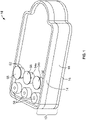
Fig. 1 is a perspective view of a lab-on-a-chip cartridge having an integral spinning membrane separator according to the present disclosure, with interior structures shaded to show detail. -
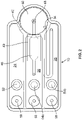
Fig. 2 is a top view of the lab-on-a-chip cartridge ofFig. 1 . -
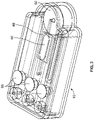
Fig. 3 is a further perspective view of the lab-on-a-chip cartridge ofFig. 1 . -
Figs. 4A-4E are top views of the lab-on-a-chip cartridge ofFig. 1 showing the workflow through the cartridge. -
Fig. 5 is a further perspective view of the lab-on-a-chip cartridge ofFig. 1 showing the bottom face of the cartridge. -
Figs. 6A and 6B are perspective views of the lab-on-a-chip cartridge ofFig. 1 in combination with a separate drive mechanism for rotating the membrane of the separator. -
Figs. 7A and 7B are exploded perspective views of the lab-on-a-chip cartridge ofFig. 1 showing the top surface and the bottom surface, respectively, of the subparts of the cartridge. -
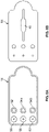
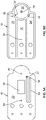
Figs. 8A-8D are top and bottom views of the top plate of the lab-on-a-chip cartridge ofFig. 1 . -
Figs. 9A-9D are top and bottom views of the middle plate of the lab-on-a-chip cartridge ofFig. 1 . -
Figs. 10A-10D are top and bottom views of the bottom plate of the lab-on-a-chip cartridge ofFig. 1 . -
Fig. 11 is a perspective view of the lab-on-a-chip cartridge ofFig. 1 having an interface associated with the top plate that provides for, among other things, viewing of the chip in combination with a microscope objective lens. -
Fig. 12 is an exploded perspective view of the lab-on-a-chip cartridge, interface, and lens ofFig. 11 . -
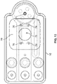
Fig. 13 is a top view of the top plate of the lab-on-a-chip cartridge in combination with the interface. -
Fig. 14 is a top view of the top plate of the lab-on-a-chip cartridge ofFig. 13 with the interface removed. - The embodiments disclosed herein are for the purpose of providing a description of the present subject matter, and it is understood that the subject matter may be embodied in various other forms and combinations not shown in detail. Therefore, specific designs and features disclosed herein are not to be interpreted as limiting the subject matter as defined in the accompanying claims.
- Turning to the drawings, a lab-on-
a-chip cartridge 10 is provided that comprises ahousing 12 having a series separate chambers on the interior thereof. As best seen inFigs. 7-10 , thehousing 12 comprises atop plate 14, abottom plate 16, and an intermediate ormiddle plate 18 positioned between the top and bottom plates. Theplates housing 12 may be made by injection molding of a rigid medical grade plastic material. By way of example, thecartridge 10 may have an overall length of approximately 80 mm, a width of 40 mm and a thickness of 18.5 mm. - More specifically, the
middle plate 18 has atop face 20 from which a plurality ofside wall members 22 depend that define the various chambers of thecartridge 10, specifically, awhole blood chamber 24, aplasma chamber 26, a red blood cell (RBC)chamber 28 and aseparation chamber 30. Thetop face 20 of themiddle plate 18 is of a sufficient thickness so that a red blood cell concentrate (RCC) flowpath 32 may be formed therein, theRCC flow path 32 including afirst port 34 on one end in communication with theseparation chamber 30 for flowing RCC into theflow path 32 and asecond port 36 on the other end for flowing RCC into theRBC chamber 28. Thetop face 20 of the middle plate also includes a cut-out 38 for receiving the lab on achip 40. The portion of theside walls 22 separating thewhole blood chamber 24 from theseparation chamber 30 includes a cut-out 42 to permit whole blood to flow fromwhole blood chamber 24 into theseparation chamber 30. Thebottom plate 16 is secured to theside wall members 22 to close the chambers and may include or define apin 90 for alignment of a rotatable filter membrane 60 (which will be described in greater detail). - The
top plate 14 has abottom face 44 that, when thecartridge 10 is assembled, contacts thetop face 20 of themiddle plate 18. Thebottom face 44 of thetop plate 14 is of a sufficient thickness so that aplasma flow path 46 may be formed that is aligned with the lab-on-a-chip 40 mounted to thetop face 20 of themiddle plate 18, so that plasma may flow from theseparation chamber 30 through aport 48 in thetop face 20 of themiddle plate 18, into theplasma flow path 46 where it contacts the lab-on-a-chip device 40, and then flow into theplasma chamber 26 through aport 50 in thetop face 20 of themiddle plate 18. - An input or
injection port 52 is formed through thebottom face 44 of thetop plate 14 and thetop face 20 of themiddle plate 18, through which whole blood may be injected into thewhole blood chamber 24. Further, thebottom face 44 of thetop plate 14 and thetop face 20 of themiddle plate 18 also includeextraction ports extraction port 54a) or red blood cells (extraction port 54b) may be withdrawn for additional testing, such as elution assays. Anadhesive seal 56 preferably overlies each of the injection andextraction ports - Each of the whole blood, plasma and red
blood cell chambers pump interface 58 associated therewith through thebottom face 44 of thetop plate 14 and thetop face 20 of themiddle plate 18. The pump interfaces 58 may each be in the form of a recessed well formed in thebottom face 44 of thetop plate 14, with a flexible diaphragm (not shown) overlying each recessed well to seal the interface. Positive and negative pressure is applied to the diaphragms through a separate device (not shown), to direct fluid flow through the various chambers of the cartridge. - In keeping with the disclosure, a
rotatable filter membrane 60 is disposed within theseparation chamber 30, so that thecartridge 10 includes an integral spinning membrane separator for separating whole blood into plasma and red blood cell fractions. The use of spinning member separators is well established in the field of apheresis, where whole blood is withdrawn from a patient or donor or other blood source (which may include precollected blood in a container), separated into its constituents (e.g., plasma, red blood cells, white blood cells, and platelets), and one or more of the constituents reinfused into the patient or donor or other blood source. A spinning membrane separator is particularly well suited for extracting plasma from whole blood. Spinning membrane separators for apheresis are described inU.S. Patent No. 5,194,145 to Schoendorfer and inU.S. Patent No. 9,381,291 to Boggs - In general, a spinning membrane separator includes a generally cylindrical housing with an internal spinning member rotatably mounted therein, a gap being formed between the interior surface of the housing and the exterior surface of the spinner. As described in the above-referenced patents, the spinner comprises a central mandrel or rotor having a central orifice, to which a porous membrane is mounted. The outer surface of the rotor is typically shaped to define a series of spaced-apart circumferential grooves that are interconnected by longitudinal grooves so that matter passing through the porous membrane is able to flow into the interior of the spinner. When used for separating plasma from whole blood, the porous membrane typically has a nominal pore size of 0.6 µm. The housing includes an inlet through which whole blood is introduced into the gap, a first outlet in communication with the gap through which separated red blood cells are flowed, and a second outlet in communication with the interior of the spinner through which separated plasma is flowed.
- The spinner is typically rotated using a magnetic drive assembly, in which an end portion of the spinner is encompassed by as ring of permanent magnetic material 62 (as seen in
Figs. 5 ,6a and 6b ), so that adrive mechanism 64 having amagnetic drive member 66 external to thecartridge 10 is indirectly coupled to therotatable filter membrane 60. As thedrive member 66 is rotated, magnetic attraction between thedrive member 66 and therotatable filter membrane 60 locks therotatable membrane 60 to thedrive member 66, so that rotation of thedrive member 66 rotates themembrane 60. To this end, one of the faces of the cartridge 10 (as shown, the lower face of the bottom plate 16) may be provided with aninterface 68, such as a recessed area, for seating and aligning the drive member of the drive mechanism with themagnetic members 62 of therotatable membrane 60. - In use, a small volume of
whole blood 100 is withdrawn from a patient and introduced into thewhole blood chamber 24 of the cartridge through theinjection port 52 by means of, e.g., a syringe (Fig. 4A ). Then thewhole blood 100 is pushed into theseparation chamber 30 of the cartridge by action of a pump associated withpump interface 58 for the whole blood chamber 24 (Fig. 4B ). Themembrane 60 is rotated through magnetic coupling to anexternal drive device 64 to create Taylor vortices in the gap between the outer surface of the filter membrane and the inner wall of theseparation chamber 30. Flow into and out of theseparation chamber 30 is controlled by pumps associated with thevarious pump interfaces 58 so that plasma 200 (with biomarkers) is pushed through themembrane 60 and flowed out of theseparation chamber 30 into theplasma flow path 46, where it contacts the lab-on-a-chip 40, while the red blood cells 300 (and other cellular material remaining in the gap) is flowed out of theseparation chamber 30 into the red blood cell fluid flow path 32 (Fig. 4C ).Whole blood 100 continues to be introduced into theseparation chamber 30, separated into plasma and red blood cells, and plasma flowed into theplasma flow path 46 and red blood cells flowed into the red bloodcell flow path 32 until the flow paths are filled (Fig. 4D ), and then spill over into the plasma and red blood cell chambers (Fig. 4E ). - In addition, the
housing 12 of thecartridge 10 may be provided with one or more interfaces to provide for additional functionality. For example, an interface may be provided on the exterior of the housing for thermal regulation (e.g., cooling or thermal cycling) of the lab-on-a-chip device, to permit imaging of the surface of the lab-on-a-chip device, or to permit the application, control and sensing of electrical signals to and from the lab-on-a-chip device as plasma flows over the surface of the device. - With reference to
Figs. 11-14 , aninterface 70 inlens interface system 110 is shown that may provide for each of the functionalities described above. For example, theinterface 70 may be associated with the top surface of thetop plate 14 to provide for thermal-electric cooling of theplasma flow path 46 by conduction through thetop plate 14. Additionally, or alternatively, theinterface 70 may include atransparent material 72 to permit imaging of the chip by means of, e.g., a microscopicobjective lens 74. Further, the interface may additionally or alternatively includeconductive pins 76 that extend through the top surface of thetop plate 14 to contactelectrical pads 78 on the surface of thechip 40 to permit that transmission of electrical signals to and from thechip 40. - Thus, an LOC device having an integrated blood separator is provided that extracts plasma from a whole blood sample that is placed directly into a point-of-care device in which it can be analyzed. By way of the device, the need for a stand-alone centrifuge is eliminated, and larger sample volumes can be collected than current static membrane plasma separation devices allow, thus enabling low concentration biomarkers to be analyzed. As a result, plasma IVD could be performed at a hospital bedside or at remote locations outside a medical center for real-time health decision making for underserved populations.
- It will be understood that the embodiments described above are illustrative of some of the applications of the principles of the present subject matter. Numerous modifications may be made by those skilled in the art without departing from the spirit and scope of the claimed subject matter, including combinations of features that are individually disclosed or claimed herein.
Claims (15)
- A lab-on-a-chip cartridge comprising:a) a housing comprising a plurality of side wall members defining first, second, third and fourth separate chambers on the interior of the cartridge;b) each of the first, second and third chambers having a pump interface associated therewith;c) at least the first chamber having a port through which a fluid may be introduced into the first chamber;d) a filter membrane rotatably mounted in the fourth chamber so as to define a gap between an outer surface of the filter membrane and an inner surface of the side wall member defining the fourth chamber;e) a first passageway in the side wall member between the first chamber and the gap in the fourth chamber;f) a first flow path extending between the fourth chamber and the second chamber to permit fluid flow between the inner surface of the membrane and the second chamber, a lab-on-a-chip device positioned within the first flow path for contact with fluid flowing into the second chamber;g) a second flow path extending between the fourth chamber and the third chamber to permit fluid flow between the gap in the fourth chamber and the third chamber; andh) an interface in an exterior surface of the fourth chamber for coupling a drive device with the filter membrane for rotating the filter membrane.
- The lab-on-a-chip cartridge of claim 1 wherein the housing further comprises a top plate, a bottom plate, and an intermediate plate between the top and bottom plates defining the side wall members, with the first flow path, second flow path, pump interfaces, port and drive device interface being contained within one of the top and bottom plates.
- The lab-on-a-chip cartridge of claim 2 further comprising a second interface associated with the top plate to provide for one or more of thermal regulation of the lab-on-a-chip device, imaging of a surface of the lab-on-a-chip device, and the application, control and sensing of electrical signals to and from the lab-on-a-chip device.
- The lab-on-a-chip cartridge of any one of claims 2-3, wherein the middle plate includes a cut-out for receiving the-lab-on-a-chip.
- The lab-on-a-chip cartridge of any one of claims 1-4 wherein each of the pump interfaces comprises a recessed well sealed with a flexible diaphragm.
- The lab-on-a-chip cartridge of any one of claims 1-5 wherein the port includes an adhesive seal and the port is preferably positioned between the pump interface of the first chamber and the first passageway.
- The lab-on-a-chip cartridge of any one of claims 1-6 wherein each of the second and third chambers includes a port through which a fluid may be extracted and each port preferably includes an adhesive seal.
- The lab-on-a-chip cartridge of claim 7 wherein the port of the second chamber is positioned between the pump interface of the second chamber and the first flow path and the port of the third chamber is positioned between the pump interface of the third chamber and the second flow path.
- The lab-on-a-chip cartridge of any one of claims 1-8 wherein the drive device interface comprises a recessed area.
- The lab-on-a-chip cartridge of any one of claims 1-9 wherein the first chamber is a whole blood chamber, the second chamber is a plasma chamber, the third chamber is a red blood cell chamber, the fourth chamber is a separation chamber, the first flow path is a plasma flow path, and the second flow path is a red blood cell flow path.
- The lab-on-a-chip cartridge of any one of claims 1-10 wherein the filter membrane includes magnetic material configured to couple the filter membrane to the drive device.
- The lab-on-a-chip cartridge of any one of claims 1-11 wherein the first, second, and third chambers are elongated and oriented substantially parallel to each other.
- The lab-on-a-chip cartridge of claim 12 whereinthe fourth chamber is substantially circular,the second chamber is positioned between the first and third chambers, and a portion of the fourth chamber is positioned between the first and third chambers.
- The lab-on-a-chip cartridge of any one of claims 1-13 wherein the first flow path is substantially linear and the first flow path preferably has a non-uniform width, with a portion of the first flow path having a maximum width being at least partially aligned with the lab-on-a-chip device.
- The lab-on-a-chip cartridge of any one of claims 1-14 wherein the second flow path is generally U-shaped.
Applications Claiming Priority (1)
| Application Number | Priority Date | Filing Date | Title |
|---|---|---|---|
| US202063091405P | 2020-10-14 | 2020-10-14 |
Publications (1)
| Publication Number | Publication Date |
|---|---|
| EP3984569A1 true EP3984569A1 (en) | 2022-04-20 |
Family
ID=78134889
Family Applications (1)
| Application Number | Title | Priority Date | Filing Date |
|---|---|---|---|
| EP21202311.3A Pending EP3984569A1 (en) | 2020-10-14 | 2021-10-13 | In vitro diagnostic device with integrated plasma separator |
Country Status (2)
| Country | Link |
|---|---|
| US (1) | US12285758B2 (en) |
| EP (1) | EP3984569A1 (en) |
Citations (4)
| Publication number | Priority date | Publication date | Assignee | Title |
|---|---|---|---|---|
| US5194145A (en) | 1984-03-21 | 1993-03-16 | William F. McLaughlin | Method and apparatus for separation of matter from suspension |
| WO2002056992A1 (en) * | 2000-11-22 | 2002-07-25 | Baxter International Inc. | Cassette with integral separation device |
| US20130334139A1 (en) * | 2011-03-11 | 2013-12-19 | Fenwal, Inc. | Membrane separation devices, systems and methods employing same, and data management systems and methods |
| US20160074565A1 (en) * | 2014-09-12 | 2016-03-17 | Asit Engineering Corp. | Portable hemodialysis machine and disposable cartridge with flow sensor |
Family Cites Families (2)
| Publication number | Priority date | Publication date | Assignee | Title |
|---|---|---|---|---|
| US20070197922A1 (en) * | 2006-02-17 | 2007-08-23 | Honeywell International Inc. | Disposable pressure sensor systems and packages therefor |
| US9404825B2 (en) * | 2011-12-07 | 2016-08-02 | Fenwal, Inc. | Apparatus with flexible member for sensing fluid pressure |
-
2021
- 2021-10-13 EP EP21202311.3A patent/EP3984569A1/en active Pending
- 2021-10-13 US US17/500,251 patent/US12285758B2/en active Active
Patent Citations (5)
| Publication number | Priority date | Publication date | Assignee | Title |
|---|---|---|---|---|
| US5194145A (en) | 1984-03-21 | 1993-03-16 | William F. McLaughlin | Method and apparatus for separation of matter from suspension |
| WO2002056992A1 (en) * | 2000-11-22 | 2002-07-25 | Baxter International Inc. | Cassette with integral separation device |
| US20130334139A1 (en) * | 2011-03-11 | 2013-12-19 | Fenwal, Inc. | Membrane separation devices, systems and methods employing same, and data management systems and methods |
| US9381291B2 (en) | 2011-03-11 | 2016-07-05 | Fenwal, Inc. | Membrane separation devices, systems and methods employing same and data management systems and methods |
| US20160074565A1 (en) * | 2014-09-12 | 2016-03-17 | Asit Engineering Corp. | Portable hemodialysis machine and disposable cartridge with flow sensor |
Also Published As
| Publication number | Publication date |
|---|---|
| US12285758B2 (en) | 2025-04-29 |
| US20220111383A1 (en) | 2022-04-14 |
Similar Documents
| Publication | Publication Date | Title |
|---|---|---|
| US8663583B2 (en) | Disposable cartridge for fluid analysis | |
| US8741233B2 (en) | Disposable cartridge for fluid analysis | |
| US8741235B2 (en) | Two step sample loading of a fluid analysis cartridge | |
| US20130164854A1 (en) | Disposable cartridge for fluid analysis | |
| US8889071B2 (en) | Apparatus and method for separating plasma | |
| US6878271B2 (en) | Implementation of microfluidic components in a microfluidic system | |
| Tachi et al. | Simultaneous separation, metering, and dilution of plasma from human whole blood in a microfluidic system | |
| CN104111324B (en) | Blood sampling transmission equipment, blood separation and test system and blood sampling Transmission system | |
| CN203989960U (en) | Biological fluid separation box, separation device and biological fluid separation and inspection system | |
| Gong et al. | Field tested milliliter-scale blood filtration device for point-of-care applications | |
| WO2004027391A1 (en) | Blood analyzer and method of separating plasma | |
| KR102089633B1 (en) | Diagnostic cartridge for microfluidic control and Molecular diagnostics system for point-of-care including the same | |
| CN215493304U (en) | Whole blood treatment and detection micro-fluidic chip | |
| US11698332B2 (en) | Devices having a sample delivery component | |
| CN108603827A (en) | The device that blood samples of patients for individuation is analyzed | |
| US20150375228A1 (en) | Devices for sorting cells in a sample and methods for use thereof | |
| JP4368383B2 (en) | Solid-liquid separation structure | |
| US12285758B2 (en) | In vitro diagnostic device with integrated plasma separator | |
| KR101092128B1 (en) | Sampler | |
| CN118067591B (en) | Consumable for blood analysis | |
| CN217502786U (en) | Liquid releasing mechanism, micro-fluidic chip and in-vitro detection device | |
| CN210356708U (en) | Blood filtering device | |
| CN112517095A (en) | Whole blood filtration and plasma quantitative micro-fluidic chip | |
| CN221674326U (en) | Microfluidic chip | |
| CN224263038U (en) | Multi-parameter integrated detection chip and device for blood body fluid analysis |
Legal Events
| Date | Code | Title | Description |
|---|---|---|---|
| PUAI | Public reference made under article 153(3) epc to a published international application that has entered the european phase |
Free format text: ORIGINAL CODE: 0009012 |
|
| STAA | Information on the status of an ep patent application or granted ep patent |
Free format text: STATUS: THE APPLICATION HAS BEEN PUBLISHED |
|
| AK | Designated contracting states |
Kind code of ref document: A1 Designated state(s): AL AT BE BG CH CY CZ DE DK EE ES FI FR GB GR HR HU IE IS IT LI LT LU LV MC MK MT NL NO PL PT RO RS SE SI SK SM TR |
|
| STAA | Information on the status of an ep patent application or granted ep patent |
Free format text: STATUS: REQUEST FOR EXAMINATION WAS MADE |
|
| 17P | Request for examination filed |
Effective date: 20221006 |
|
| RBV | Designated contracting states (corrected) |
Designated state(s): AL AT BE BG CH CY CZ DE DK EE ES FI FR GB GR HR HU IE IS IT LI LT LU LV MC MK MT NL NO PL PT RO RS SE SI SK SM TR |
|
| STAA | Information on the status of an ep patent application or granted ep patent |
Free format text: STATUS: EXAMINATION IS IN PROGRESS |
|
| 17Q | First examination report despatched |
Effective date: 20260513 |