EP3984472A1 - Clip for endoscope - Google Patents
Clip for endoscope Download PDFInfo
- Publication number
- EP3984472A1 EP3984472A1 EP21201671.1A EP21201671A EP3984472A1 EP 3984472 A1 EP3984472 A1 EP 3984472A1 EP 21201671 A EP21201671 A EP 21201671A EP 3984472 A1 EP3984472 A1 EP 3984472A1
- Authority
- EP
- European Patent Office
- Prior art keywords
- arm
- clip
- anchor
- claw
- anchors
- Prior art date
- Legal status (The legal status is an assumption and is not a legal conclusion. Google has not performed a legal analysis and makes no representation as to the accuracy of the status listed.)
- Granted
Links
Images







Classifications
-
- A—HUMAN NECESSITIES
- A61—MEDICAL OR VETERINARY SCIENCE; HYGIENE
- A61B—DIAGNOSIS; SURGERY; IDENTIFICATION
- A61B17/00—Surgical instruments, devices or methods
- A61B17/10—Surgical instruments, devices or methods for applying or removing wound clamps, e.g. containing only one clamp or staple; Wound clamp magazines
-
- A—HUMAN NECESSITIES
- A61—MEDICAL OR VETERINARY SCIENCE; HYGIENE
- A61B—DIAGNOSIS; SURGERY; IDENTIFICATION
- A61B17/00—Surgical instruments, devices or methods
- A61B17/12—Surgical instruments, devices or methods for ligaturing or otherwise compressing tubular parts of the body, e.g. blood vessels or umbilical cord
- A61B17/122—Clamps or clips, e.g. for the umbilical cord
- A61B17/1227—Spring clips
-
- A—HUMAN NECESSITIES
- A61—MEDICAL OR VETERINARY SCIENCE; HYGIENE
- A61B—DIAGNOSIS; SURGERY; IDENTIFICATION
- A61B17/00—Surgical instruments, devices or methods
- A61B17/12—Surgical instruments, devices or methods for ligaturing or otherwise compressing tubular parts of the body, e.g. blood vessels or umbilical cord
- A61B17/122—Clamps or clips, e.g. for the umbilical cord
-
- A—HUMAN NECESSITIES
- A61—MEDICAL OR VETERINARY SCIENCE; HYGIENE
- A61B—DIAGNOSIS; SURGERY; IDENTIFICATION
- A61B17/00—Surgical instruments, devices or methods
- A61B17/00234—Surgical instruments, devices or methods for minimally invasive surgery
-
- A—HUMAN NECESSITIES
- A61—MEDICAL OR VETERINARY SCIENCE; HYGIENE
- A61B—DIAGNOSIS; SURGERY; IDENTIFICATION
- A61B17/00—Surgical instruments, devices or methods
- A61B17/12—Surgical instruments, devices or methods for ligaturing or otherwise compressing tubular parts of the body, e.g. blood vessels or umbilical cord
- A61B17/128—Surgical instruments, devices or methods for ligaturing or otherwise compressing tubular parts of the body, e.g. blood vessels or umbilical cord for applying or removing clamps or clips
- A61B17/1285—Surgical instruments, devices or methods for ligaturing or otherwise compressing tubular parts of the body, e.g. blood vessels or umbilical cord for applying or removing clamps or clips for minimally invasive surgery
-
- A—HUMAN NECESSITIES
- A61—MEDICAL OR VETERINARY SCIENCE; HYGIENE
- A61B—DIAGNOSIS; SURGERY; IDENTIFICATION
- A61B17/00—Surgical instruments, devices or methods
- A61B17/28—Surgical forceps
- A61B17/29—Forceps for use in minimally invasive surgery
-
- A—HUMAN NECESSITIES
- A61—MEDICAL OR VETERINARY SCIENCE; HYGIENE
- A61B—DIAGNOSIS; SURGERY; IDENTIFICATION
- A61B17/00—Surgical instruments, devices or methods
- A61B17/08—Wound clamps or clips, i.e. not or only partly penetrating the tissue ; Devices for bringing together the edges of a wound
- A61B17/083—Clips, e.g. resilient
-
- A—HUMAN NECESSITIES
- A61—MEDICAL OR VETERINARY SCIENCE; HYGIENE
- A61B—DIAGNOSIS; SURGERY; IDENTIFICATION
- A61B17/00—Surgical instruments, devices or methods
- A61B17/00234—Surgical instruments, devices or methods for minimally invasive surgery
- A61B2017/00292—Surgical instruments, devices or methods for minimally invasive surgery mounted on or guided by flexible, e.g. catheter-like, means
- A61B2017/00336—Surgical instruments, devices or methods for minimally invasive surgery mounted on or guided by flexible, e.g. catheter-like, means with a protective sleeve, e.g. retractable or slidable
-
- A—HUMAN NECESSITIES
- A61—MEDICAL OR VETERINARY SCIENCE; HYGIENE
- A61B—DIAGNOSIS; SURGERY; IDENTIFICATION
- A61B17/00—Surgical instruments, devices or methods
- A61B17/00234—Surgical instruments, devices or methods for minimally invasive surgery
- A61B2017/00292—Surgical instruments, devices or methods for minimally invasive surgery mounted on or guided by flexible, e.g. catheter-like, means
- A61B2017/0034—Surgical instruments, devices or methods for minimally invasive surgery mounted on or guided by flexible, e.g. catheter-like, means adapted to be inserted through a working channel of an endoscope
-
- A—HUMAN NECESSITIES
- A61—MEDICAL OR VETERINARY SCIENCE; HYGIENE
- A61B—DIAGNOSIS; SURGERY; IDENTIFICATION
- A61B17/00—Surgical instruments, devices or methods
- A61B2017/00367—Details of actuation of instruments, e.g. relations between pushing buttons, or the like, and activation of the tool, working tip, or the like
-
- A—HUMAN NECESSITIES
- A61—MEDICAL OR VETERINARY SCIENCE; HYGIENE
- A61B—DIAGNOSIS; SURGERY; IDENTIFICATION
- A61B17/00—Surgical instruments, devices or methods
- A61B2017/00831—Material properties
-
- A—HUMAN NECESSITIES
- A61—MEDICAL OR VETERINARY SCIENCE; HYGIENE
- A61B—DIAGNOSIS; SURGERY; IDENTIFICATION
- A61B17/00—Surgical instruments, devices or methods
- A61B2017/00831—Material properties
- A61B2017/00964—Material properties composite
-
- A—HUMAN NECESSITIES
- A61—MEDICAL OR VETERINARY SCIENCE; HYGIENE
- A61B—DIAGNOSIS; SURGERY; IDENTIFICATION
- A61B17/00—Surgical instruments, devices or methods
- A61B17/12—Surgical instruments, devices or methods for ligaturing or otherwise compressing tubular parts of the body, e.g. blood vessels or umbilical cord
- A61B2017/12004—Surgical instruments, devices or methods for ligaturing or otherwise compressing tubular parts of the body, e.g. blood vessels or umbilical cord for haemostasis, for prevention of bleeding
-
- A—HUMAN NECESSITIES
- A61—MEDICAL OR VETERINARY SCIENCE; HYGIENE
- A61B—DIAGNOSIS; SURGERY; IDENTIFICATION
- A61B17/00—Surgical instruments, devices or methods
- A61B17/28—Surgical forceps
- A61B17/29—Forceps for use in minimally invasive surgery
- A61B2017/2901—Details of shaft
- A61B2017/2906—Multiple forceps
-
- A—HUMAN NECESSITIES
- A61—MEDICAL OR VETERINARY SCIENCE; HYGIENE
- A61B—DIAGNOSIS; SURGERY; IDENTIFICATION
- A61B17/00—Surgical instruments, devices or methods
- A61B17/28—Surgical forceps
- A61B17/29—Forceps for use in minimally invasive surgery
- A61B2017/2926—Details of heads or jaws
Definitions
- the present invention relates to clips configured to grasp tissue of a patient in a surgical procedure and can be used with surgical tools such as endoscopes.
- Endoscopic clips i.e., endoclips
- endoclips are surgical tools used with endoscopes that can grasp tissue within a human body. Endoclips have found use in therapeutic procedures such as to prevent tissue bleeding, closing perforations, and other surgical procedures. There are many types of endoclips differing in shape and/or size, which can be administered using single use and reloadable systems, and may or may not open and close to facilitate placement of the clip in the body.
- JP 2015008858 discloses an endoscope clip for grasping body tissue that includes protrusions on inner surfaces of arm plates of the clip.
- the protrusions are directed inward to face each other and are designed to facilitate holding tissue between the arms of the clip when the clip is closed.
- the invention is directed to the object to provide a clip configured to grasp tissue of a patient in a surgical procedure that can be used with surgical tools such as endoscopes.
- a clip for gripping tissue having the features defined in claim 1 is provided.
- the clip according to the invention includes an anchor which can more readily attach to tissue of a patient upon contact with the tissue than clips without an anchor. Clips of the present invention can more readily facilitate grasping tissue when the clip approaches such tissue at an angles less than perpendicular to the tissue, for example.
- a clip for gripping tissue having a first arm, with a first claw at a distal end of the first arm, and a second arm with a second claw at a distal end of the second arm is provided.
- the first arm and the second arm are configured to move in a direction toward each other to close the clip.
- the first claw and second claw face each other.
- the first and second arms can move in a reciprocal direction toward and away from each other to close and open the clip.
- the first arm and second arm are configured to move in a direction toward each other to close the clip and once the arms close, the clip can be locked from opening.
- the clip includes one or more anchors such as a first anchor on the first arm.
- the first anchor protrudes from the first arm in a direction other than the direction that the first arm and second arm are configured to move toward each other to close the clip.
- Additional embodiments of the clip include one or more of the following features individually or combined.
- the clip can also include a second anchor such as on the second arm.
- the second anchor can protrude from the second arm in a direction other than the direction that the first arm and the second arm are configured to move toward each other to close the clip.
- the clip includes the first anchor and the second anchor.
- the clip can be assembled with a pressing tube, which can be connected to a sheath.
- the clip can also be connected to a wire directly or through a connection member.
- the assembly can include a cover to shield the first anchor and optional second anchor when the clip is retracted in a pressing tube.
- the first and optional second anchor can protrude through slits in the arms.
- the first and optional second anchor can protrude from the arms in a direction that is orthogonal to a plane defined by the first and second arm.
- the anchors can be configured to rotate toward a plane defined by the first and second arm.
- of the first arm and the second arm are configured to bend.
- the clip may further comprise a pressing tube in which the clip can slidably retract to close the clip.
- the clip may comprise a cover shielding at least one of the first anchor and the optional second anchor when the clip is retracted in the pressing tube.
- the first anchor may protrude through a slit in the first arm.
- the optional second anchor may protrude through a slit in the second arm.
- the clip when in a closed state, may form a width (W) defined by opposite ends of the first and second anchors, which is less than a width of a pressing tube or less than a width of a channel in a treatment tool.
- the pressing tube may have an opening that allows at least one of the first anchor and the optional second anchor to enter the pressing tube when the clip is retracted in the pressing tube.
- the first anchor may protrude from the first arm in a direction that is orthogonal to a plane defined by the first and second arm.
- the second anchor may protrude from the second arm in a direction that is orthogonal to a plane defined by the first and second arm.
- the first anchor may be configured to rotate toward the plane defined by the first and second arm.
- the optional second anchor may be configured to rotate toward the plane defined by the first and second arm.
- the first anchor may protrude from the first arm in a direction divergent from the first claw.
- the first claw may have a gap so that the first anchor can be seen through the gap of the first claw.
- the first anchor may have a width that is smaller or larger than a width of the first claw.
- the optional second anchor may protrude from the second arm in a direction divergent from the second claw.
- the second claw may have a gap so that the second anchor can be seen through the gap of the second claw.
- the second anchor may have a width that is smaller or larger than a width of the second claw.
- At least one of the first anchor and the optional second anchor is in the form of a hook.
- both the first anchor and the optional second anchor are in the form of a hook.
- the first arm may have a first marker which identifies the location of the first anchor.
- the second arm may have a second marker which identifies the location of the second anchor.
- At least one of the first arm and the second arm is configured to bend.
- both the first arm and the second arm are configured to bend.
- At least one of the first arm and the second arm is configured to lock in a bent state.
- both the first arm and the second arm are configured to lock in a bent state.
- the second arm includes the optional second anchor.
- At least one of the first anchor and the optional second anchor is made of a bioadsorbale material.
- both the first anchor and the second anchor are made of a bioadsorbale material.
- Clips of the present disclosure are useful in therapeutic procedures of a patient such as to prevent tissue bleeding, closing perforations and hemostasis, and suture contraction of the inner wound, marking lesions and traction (mucosal elevation) and other surgical procedures.
- patient as used herein, comprises any and all organisms and includes the term “subject.”
- a patient can be a human or an animal.
- a clip operation tool actuates the clip by an operational wire typically housed in a flexible tube in which the operational wire can advance and retract longitudinally in the flexible tube by operating an handle of the tool.
- references herein to the term “distal” are to a direction away from the operating handle, while references to the term “proximal” are to a direction towards the operating handle.
- Clip operation tools such as those described in U.S. Patent Nos. 8,480,685 and 9,949,740 can be used with the clips of the present disclosure.
- FIGS. 1 through 20 Various embodiments and aspects of a clip according to the present disclosure will be described with references to FIGS. 1 through 20 .
- a clip 10 for gripping biological tissue of a patient has a first arm 12, which has a first claw 12a at a distal end of the first arm 12, and a second arm 13, which has a second claw 13a at a distal end of the second arm 13.
- first claw 12a and second claw 13a face each other and first arm 12 and second arm 13 are configured to move in a reciprocal direction R toward and away from each other to close and open the clip.
- the first and second claws can be on the same or approximately the same plane such that when the arms close, the claws contact each other.
- Clips of the present disclosure advantageously include one or more anchors protruding from the first arm and/or the second arm.
- An anchor as used herein includes a structure that can attach to tissue of a patient upon contact with minimal force and can include, for example, a protrusion, hook, barb, spike, etc.
- the one or more anchors protrude from their respective arms in a direction other than the direction that the first and second arms are configured to move toward each other to close the clip.
- the anchor can protrude in a direction divergent from a claw or in a direction that is orthogonal to a plane defined by the first and second arm (in a vertical direction relative to an arm) or protruding at any other direction other than the direction the first and second arms are configured to move toward each other to close the clip.
- first arm 12 includes a first anchor 14a on an outer surface of first arm 12 protruding in a direction divergent from first claw 12a and a second arm 13 includes a second anchor 14b on an outer surface thereon protruding in a direction divergent from second claw 13a.
- Clip 10 can deploy from within a pipe (also referred to herein as a pressing tube) 16 which can be coupled to a flexible tube 18.
- a pipe also referred to herein as a pressing tube
- arms 12 and 13 which are biased toward an open, tissue receiving configuration as shown in FIGS. 1C and 1D , can be closed by actuating an operational wire (not shown) coupled to the clip to slidably move the clip proximally and distally in the pipe.
- the operational wire can advance and retract longitudinally in the flexible tube (not shown) by operating a handle of the tool (not shown). Slidably moving the clip distally and proximally opens and closes the clip by moving the arms and claws toward and away from each other. In some embodiments, once the clip is retracted in a pressing tube, the clip can be locked from opening.
- an advantage of clips of the present disclosure is that they can attach to tissue even when the approach A of the clip is not perpendicular to the tissue, e.g. FIG. 1C illustrates a perpendicular approach while FIG. 1D illustrates a tangential approach.
- anchor 14b on arm 13 can catch tissue T near a defect D.
- the claw and arm can elevate the tissue so that the claws of the arms can more readily grasp the tissue.
- the clip can be rotated to further grasp the tissue in the claw of the arm with the anchor attached to the issue.
- one or more anchors on outer surfaces of arms of clips of the present disclosure can prevent the distal end of an arm of a clip from slipping during a tangential approach to tissue ( FIG. 1D ).
- FIGS. 2A through 6B illustrate different aspects of clips of the present disclosure and different ways to mitigate contact of the anchors with other parts of a clip tool or endoscope.
- FIGS. 2A-2E show a cover that can shield anchors of the clip.
- a cover 21 is attached to pressing tube (pipe) 16 and extending distally from pressing tube 16.
- Clip 10 can close ( FIG. 2B ) by slidably retracting in pressing tube 16.
- the cover can extend sufficiently distally to shield one or more anchors on outer surfaces of the arms when the clip is retracted in the pressing tube.
- cover 21 extends distally sufficiently to shield anchors 14a and 14b when clip 10 is retracted in pressing tube 16.
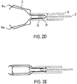
- FIGS. 2C-2E illustrate different attachment locations for a cover that can shield anchors of the clip.
- FIG. 2C shows cover 21 attached to sheath 18.
- FIGS. 2D-2E show how cover 21 can be attached to a connection member 29 or wire 27.
- FIG. 2D shows the clip in an open state with the anchors 14a, 14b exposed and
- FIG. 2E shows the clip in a closed state with the anchors shielded by cover 21. Irrespective of the location of attachment, the cover extends sufficiently distally to shield the anchors when the clip is retracted in the pressing tube.
- Cover 21 can be made of a plastic or other elastic material or a metal and can be attached by an adhesive or weld.
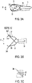
- FIGS. 3A-3C and 4A-4C show flexible anchors that can protrude through slits in arms of a clip after the clip is opened.
- anchors 34a and 34b can be shielded by inner surfaces of first arm 32 and second arm 33 of clip 30 when the clip is in the closed state ( FIG. 3A ).
- the anchors 34a and 34b are connected to clip 30 by flexible members 31a and 31b, respectively.
- anchor 34a protrudes through slit 35 in first arm 32 of clip 30.
- Anchor 34b similarly protrudes through a slit in second arm 33 when clip 30 is in an open state, which is not illustrated for convenience. In this way, the anchors can be shielded prior to deploying the clip, such as deploying clip 30 from pressing tube 16.
- FIGS. 4A-4H show flexible anchors that can protrude through slits in arms of a clip after the clip is opened.
- anchors 44a and 44b can be retracted toward first and second arms 42 and 43, respectively, when the clip 40 moves toward a closed state ( FIG. 4B-4C ).
- the anchors 44a and 44b are connected to clip 40 by flexible members 41a and 41b, respectively.
- anchor 44a protrudes through slit 45 in first arm 42 of clip 40 by flexible member 41a.
- Anchor 44b similarly protrudes through a slit in second arm 43 when clip 40 is in an open state, which is not illustrated for convenience. In this way, the anchors can be brought toward the arms of the clip when the clip is retracted in pressing tube 16.
- clips and the flexible members can be in a closed state when inserted in a tool such as an endoscope ( FIGS. 4E and 4F ). Since the clip arms and flexible members are bias toward an open state, the clip arms and flexible members open in an operation of exiting a channel of the tool ( FIGS. 4D and 4G ).
- a handle (not shown) connected to a proximal end of wire (not shown) operates the wire 47 to retract the clip 40 in a pressing pipe 16 to close the clip arms.
- Certain clip devices can include a connection member 49 to engage and release a pressing tube from the sheath 18 ( FIG. 4H ).
- connection members to engage and disengage a distal end of the clip from the wire.
- connection member can include internal engaging and disengaging elements.
- the flexible members can be connected to the wire or connection member and retracted in the pressing tube ( FIG. 4H ).
- FIGS. 5A and 5B show clip 50 for gripping biological tissue of a patient having first arm 12, which has a first claw 12a at a distal end of the first arm 12 and a second arm 13, which has a second claw 13a at a distal end of the second arm 13.
- first claw 12a and second claw 13a face each other and first arm 12 and second arm 13 are configured to move in a reciprocal direction R toward and away from each other to close and open the clip.
- first arm 12 includes an anchor 14a protruding from the first arm 12 in a direction divergent from first clam 12a and a second arm 13 includes a second anchor 14b protruding from the second arm 13 in a direction divergent from second claw 13a.
- Clip 50 can deploy from within a pressing tube 16 to an open state ( FIG. 5A ).
- the clip When in a closed state ( FIG. 5B ), the clip forms a width -W defined by the distance between the distal ends of the anchors, which is less than a width of pressing tube 16 or less than a width of a channel in a treatment tool 51 such as a channel in an endoscope so that the anchors protruding from the arms 14a, 14b do not contact or minimally contact the channel.
- FIGS. 6A and 6B show a clip 10 having first arm 12, which has a first claw 12a at a distal end of the first arm 12 and a second arm 13, which has a second claw 13a at a distal end of the second arm 13.
- first claw 12a and second claw 13a face each other and first arm 12 and second arm 13 are configured to move in a direct toward each other to close the clip.
- claws 12a and 13a make contact when the arms are closed.
- the clip includes an anchor 64a on first arm 12 and includes an anchor 64b on second arm 13 in which both anchors protrude in a direction that is orthogonal to a plane formed by first and second arm 12 and 13.
- Pressing tube 66 has an opening, e.g., diameter D, sufficiently large to allow the anchors to enter the tube when the clip is retracted in the pressing tube.
- FIG. 6B shows the anchors 64 in pressing tube 66 when the clip is retracted in the pressing tube and the clip is in a closed state.
- the arms, claws and anchors can have suitable forms, such as the form of a wire (as in the embodiments illustrated in, e.g., FIGS. 1A to 1D , or as the form of a ribbon (as in the embodiments illustrated in, e.g., FIGS. 6A and 6B ), or can have a mixed form, such as one of the arms and claws in the form of a ribbon and the anchors in the form of a wire.
- FIGS. 7 through 8 illustrate other aspects of anchors that can be included on arms of clips.
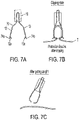
- FIGS. 7A-7C show clip 70 for gripping biological tissue T of a patient has a first arm 12, which has a first claw 12a at a distal end of the first arm 12 and a second arm 13, which has a second claw 13a at a distal end of the second arm 13.
- First claw 12a and second claw 13a face each other.
- first arm 12 includes a first anchor 74a on an outer surface of first arm 12 protruding in a direction divergent from first clam 12a and a second arm 13 includes a second anchor 74b on an outer surface thereon protruding in a direction divergent from second claw 13a.
- first and second anchors, 74a and 74b are made of a bioadsorbable material.
- Such anchors made of bioadsorbable can be initially attached to the clip arms by an adhesive, such as a bioadsorbable adhesive.
- FIGS. 8-11 show anchors that protrude in a direction that is orthogonal to a plane defined by the first and second arm.
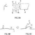
- FIGS. 8 and 10 show clip 10 for gripping biological tissue T of a patient including a first arm 12, which has a first claw 12a at a distal end of the first arm 12, and a second arm 13, which has a second claw 13a at a distal end of the second arm 13, in which first claw 12a and second claw 13a face each other and first arm 12 and second arm 13 are configured to move toward each other to close the clip.
- first arm 12 includes a first anchor 84a in which the anchor protrude from the first arm in a direction that is orthogonal to a plane P defined by the first and second arm.
- first arm 12 includes a first anchor 104a in which the anchor protrude from the first arm in a direction that is orthogonal to a plane defined by the first and second arm and second arm 13 includes a second anchor 104b in which the anchor protrude from the second arm in a direction that is orthogonal to a plane defined by the first and second arm.
- Anchors 104a and 104b protrude in opposite directions from a plane defined by the arms.
- a configuration in which the anchor or anchors protrude in a direction that is orthogonal to a plane defined by the first and second arm advantageously can cause tissue caught by the orthogonal anchor ( FIGS. 8B , 10B ) to elevate when the arms approach each other (81, 101 in FIG. 8C , FIG. 10C , presectively) which facilitates grasping the tissue in the arms.
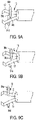
- FIGS. 9A-9C illustrate clips having more than one anchor per arm, and/or in which anchors protrude in different directions from each other.
- FIG. 9A shows first arm 12 with two anchors.
- a first anchor 94a protrudes from first arm 12 in a direction that is orthogonal to a plane defined by the first and second arm, a second anchor 94c which protrudes from first arm 12 in a direction that is orthogonal to a plane defined by the first and second arm but opposite of first anchor 94a.
- Second arm 13 also has two anchors.
- a third anchor 94b protrudes from second arm 13 in a direction that is orthogonal to a plane defined by the first and second arm, a fourth anchor 94d which protrudes from second arm 13 in a direction that is orthogonal to a plane defined by the first and second arm but opposite of third anchor 94c.
- FIG. 9B shows first arm 12 with two anchors 94a, 94b and second arm 13 with a third anchor 94d.
- FIG. 9C shows each of the arms of the clips having one anchor 94a, 94d but the anchors protrude in opposite directions from a plane defined by the arms.
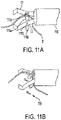
- FIGS. 11A-11B and 11C illustrate anchors configured to rotate into the plane of the arms when the clip is retracted in a pressing tube.
- first and second anchors 114a, 114b are attached to their respective first and second arms 12, 13 by a structure, for example pins 111a, 111b, which allows the anchors to rotate 119 toward the plane defined by the arms when the clip is retracted into the pressing tube 116 and an edge of the pressing tube contacts the anchors.
- FIG. 11C shows another structure configured to rotate the anchor into the plane of the arms of a clip when the arms are slidable retracted or extended from a pressing tube.
- anchor 114 is formed integral to clip arm 13 and biased in an open state but when retracted in pressing pipe 116 is in a closed state.
- no pins are needed on the arms of the clips to include anchors which can rotate toward the plane defined by the arms when the clip is retracted into the pressing tube 116.
- the anchors have a spring open bias and pops-out of the pressing tube upon extended distally from the tube.
- FIGS. 12-13 illustrate clips having anchors that can be more easily identified when the clips are is use.
- FIGS. 12A and 12B show first arm 12 and second arm 13 with a marker 121 on the respective arms which identifies the location of first anchor 124a or 124b on the respective arms.
- the user can identify the location of the anchors by the markers 121a, 121b on the respective first or second arm.
- the markers 121 on the arms of the clip can be caused by a fluorescent marker, color, symbol, texture on the arm such as a roughness, etc. or equivalent on the arm at the location of the anchor.
- FIGS. 13A and 13B illustrate clips with claws that have a gap or in which a width of a claw is greater or less than a width of the anchor so that the anchors can be more readily observed when the clip is in use.
- FIGS. 13A-13B show clip 10 with first and second arms 12, 13 having first and second claws 12a, 13a in which first and second anchors 134a, 134b have a width that is smaller than the width of the claws 12a, 13a or a width that is greater than the width of the claws 12a, 13a) to facilitate observing the anchors when in use.
- the claws can include a gap to facility observing the anchors.
- FIG. 13A shows first claw 12a with a gap which facilitates observing anchor 134a and second clam 13a has a gap which facilitates observing anchor 134b.
- FIGS. 14-20 schematically illustrate clip arms in accordance with the present disclosure that can further advantageously apply a vertical force to tissue when the clip is tangential thereto and can bend to facility placing multiple clips in close proximity to each other.
- FIGS. 14A and 14B show a side view of clip 10 showing first arm 12 with anchor 144 protruding from the first arm 12 in a vertical direction from the longitudinal direction of the first arm.
- anchor 144 is in the shape of a hook and in a direction that is orthogonal to a plane defined by the first and second arm of the clip, which allows the clip to be placed vertically on the tissue.
- anchor 144 attaches to tissue T, the clip can be rotated 141 which results in a vertical force on the tissue.
- Another advantage of anchors on clips as set forth in the present disclosure is that such clips can be pressed firmly against the mucosa allowing more tissue to be inserted between the claws and more tissue grasped by the clip.
- clips of the present disclosure can be disconnected from a surgical tool and clipped on tissue of a patient.
- the clip arms can be configured to bend.
- a clip 150a can be configured to be released from a surgical tool after the clip is attached to tissue of a patient.
- placement of a second clip 150b is somewhat limited due to the proximal end of the clip and any member attached to the proximal end of the clip such as a pressing tube 156.
- clip 150c has a first arm 152 and second arm (not shown) with a first anchor 154 on first arm 152 and pressing tube 156.
- clip 150c includes a bending portion or member 151 along the clip. In this way, clips having anchors and arms 150c and 150d configured to bend can be more readily placed adjacent to one another when attached to tissue of a patient.
- FIGS. 16-20 schematically illustrate various structural features which configure a clip arm to bend.
- FIGS. 16A and 16C show clip 160 having a first arm 162 which includes a member 161 with high elasticity.
- the second arm of clip 160 would also have a member with high elasticity, but is not illustrates in the side view of FIG. 16 .
- the clip arms are bias to be in a bent state such that when the clip is loaded in pressing tube 166, the clip arms are in a straight position L, but when deployed from pressing tube 166, clip arm 162 bends as shown in the unloaded state U.
- a clip arms can have one or more springs to bias the clip arms in a bent state.
- clip arm 172 When such a clip is placed in a channel of an endoscope 165, the arms would be in a straight state but when deployed from the channel, the arms would bend ( FIG. 16B ).
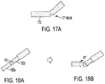
- clip arm 172 In FIG. 17A , clip arm 172 includes a notch 171 which can relieve stress when the arm is bent.
- FIGS. 18-20 Other structures that could be used to configure the arms of clips of the represent disclosure to bend are illustrated in FIGS. 18-20 .
- clip arm 182 includes two parts 182a, 182b articulated together through joint 181.
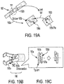
- FIGS. 19A - 19C illustrate locking configurations of an arm of a clip configured to bend.
- FIG. 19A shows clip arm 192 comprised of two articulating parts 192a, 192b connected by a joint 191.
- Part 192b can have a pin 195a that moves along a grove 195b when the arm is moving to a bent position.
- the pin can pass over a projection 195c in the grove 195b to lock the arm in the bent state.
- FIGS. 19B-19C show clip arm 195 comprised of two articulating parts 195a, 195b connected by a joint 191 in which the inner part 195a of arm 195 has a concavity 197a and the outer part 195b of arm 195 has a convexity 197b such that when the outer part 195b of arm 195 rotates to position the arm in a bend state the concavity 197a fits in convexity 197b as shown in the cross sectional view of arm 195.
- FIGS. 20A - 20D illustrate clip arms articulated together through springs.
- arm 202 includes two parts 202a, 202b connected together by a spring 201.
- the clip arm is biased to be in a bent state such that when the clip is loaded in pressing tube 206, the clip arm is in a straight position L, but when deployed from pressing tube 206, clip arm 202 bends as shown in the unloaded state U in FIG. 20B .
- the arms of the clip would be in a straight state but when deployed from the channel, the arms would bend ( FIG. 20C and 20D ).
- the clip arms can be made of a shape memory alloy, such as Nitinol, and are in the straightened or bent configuration based on stress state or temperature.
Landscapes
- Health & Medical Sciences (AREA)
- Life Sciences & Earth Sciences (AREA)
- Surgery (AREA)
- Molecular Biology (AREA)
- General Health & Medical Sciences (AREA)
- Biomedical Technology (AREA)
- Heart & Thoracic Surgery (AREA)
- Medical Informatics (AREA)
- Nuclear Medicine, Radiotherapy & Molecular Imaging (AREA)
- Animal Behavior & Ethology (AREA)
- Engineering & Computer Science (AREA)
- Public Health (AREA)
- Veterinary Medicine (AREA)
- Reproductive Health (AREA)
- Vascular Medicine (AREA)
- Ophthalmology & Optometry (AREA)
- Surgical Instruments (AREA)
- Endoscopes (AREA)
Abstract
Description
- This application claims the benefit of
U.S. Provisional Application No. 63/092,981 filed 16 October 2020 - The present invention relates to clips configured to grasp tissue of a patient in a surgical procedure and can be used with surgical tools such as endoscopes.
- In the discussion that follows, reference is made to certain structures and/or methods. However, the following references should not be construed as an admission that these structures and/or methods constitute prior art. Applicant expressly reserves the right to demonstrate that such structures and/or methods do not qualify as prior art against the present invention.
- Endoscopic clips, i.e., endoclips, are surgical tools used with endoscopes that can grasp tissue within a human body. Endoclips have found use in therapeutic procedures such as to prevent tissue bleeding, closing perforations, and other surgical procedures. There are many types of endoclips differing in shape and/or size, which can be administered using single use and reloadable systems, and may or may not open and close to facilitate placement of the clip in the body.
- For example,
JP 2015008858 - The invention is directed to the object to provide a clip configured to grasp tissue of a patient in a surgical procedure that can be used with surgical tools such as endoscopes.
- In order to address this object, a clip for gripping tissue having the features defined in claim 1 is provided.
- The clip according to the invention includes an anchor which can more readily attach to tissue of a patient upon contact with the tissue than clips without an anchor. Clips of the present invention can more readily facilitate grasping tissue when the clip approaches such tissue at an angles less than perpendicular to the tissue, for example.
- A clip for gripping tissue having a first arm, with a first claw at a distal end of the first arm, and a second arm with a second claw at a distal end of the second arm is provided. The first arm and the second arm are configured to move in a direction toward each other to close the clip. In some embodiments, the first claw and second claw face each other. In further embodiments, the first and second arms can move in a reciprocal direction toward and away from each other to close and open the clip. In other embodiments, the first arm and second arm are configured to move in a direction toward each other to close the clip and once the arms close, the clip can be locked from opening.
- The clip includes one or more anchors such as a first anchor on the first arm. The first anchor protrudes from the first arm in a direction other than the direction that the first arm and second arm are configured to move toward each other to close the clip.
- Additional embodiments of the clip include one or more of the following features individually or combined.
- Optionally, the clip can also include a second anchor such as on the second arm. When present, the second anchor can protrude from the second arm in a direction other than the direction that the first arm and the second arm are configured to move toward each other to close the clip. In several embodiments, the clip includes the first anchor and the second anchor.
- For example, the clip can be assembled with a pressing tube, which can be connected to a sheath. The clip can also be connected to a wire directly or through a connection member. In some embodiments, the assembly can include a cover to shield the first anchor and optional second anchor when the clip is retracted in a pressing tube. In other embodiments, the first and optional second anchor can protrude through slits in the arms. In still further embodiments, the first and optional second anchor can protrude from the arms in a direction that is orthogonal to a plane defined by the first and second arm. In other embodiments, the anchors can be configured to rotate toward a plane defined by the first and second arm. In some embodiments, of the first arm and the second arm are configured to bend.
- In particular, the clip may further comprise a pressing tube in which the clip can slidably retract to close the clip. Alternatively or additionally, the clip may comprise a cover shielding at least one of the first anchor and the optional second anchor when the clip is retracted in the pressing tube.
- The first anchor may protrude through a slit in the first arm. Alternatively or additionally, the optional second anchor may protrude through a slit in the second arm.
- The clip, when in a closed state, may form a width (W) defined by opposite ends of the first and second anchors, which is less than a width of a pressing tube or less than a width of a channel in a treatment tool.
- The pressing tube may have an opening that allows at least one of the first anchor and the optional second anchor to enter the pressing tube when the clip is retracted in the pressing tube.
- The first anchor may protrude from the first arm in a direction that is orthogonal to a plane defined by the first and second arm. Alternatively or additionally, the second anchor may protrude from the second arm in a direction that is orthogonal to a plane defined by the first and second arm.
- The first anchor may be configured to rotate toward the plane defined by the first and second arm. Alternatively or additionally, the optional second anchor may be configured to rotate toward the plane defined by the first and second arm.
- The first anchor may protrude from the first arm in a direction divergent from the first claw. Alternatively or additionally, the first claw may have a gap so that the first anchor can be seen through the gap of the first claw. The first anchor may have a width that is smaller or larger than a width of the first claw. The optional second anchor may protrude from the second arm in a direction divergent from the second claw. The second claw may have a gap so that the second anchor can be seen through the gap of the second claw. Alternatively or additionally, the second anchor may have a width that is smaller or larger than a width of the second claw.
- At least one of the first anchor and the optional second anchor is in the form of a hook. Preferably, both the first anchor and the optional second anchor are in the form of a hook.
- The first arm may have a first marker which identifies the location of the first anchor. Similarly, the second arm may have a second marker which identifies the location of the second anchor.
- At least one of the first arm and the second arm is configured to bend. Preferably, both the first arm and the second arm are configured to bend.
- At least one of the first arm and the second arm is configured to lock in a bent state. Preferably, both the first arm and the second arm are configured to lock in a bent state.
- Preferably, the second arm includes the optional second anchor.
- At least one of the first anchor and the optional second anchor is made of a bioadsorbale material. Preferably, both the first anchor and the second anchor are made of a bioadsorbale material.
- Additional advantages of the present invention will become readily apparent to those skilled in this art from the following detailed description, wherein only the preferred embodiment of the invention is shown and described, simply by way of illustration of the best mode contemplated of carrying out the invention. As will be realized, the invention is capable of other and different embodiments, and its several details are capable of modifications in various obvious respects, all without departing from the invention. Accordingly, the drawings and description are to be regarded as illustrative in nature, and not as restrictive.
- Reference is made to the attached drawings, wherein elements having the same reference numeral designations represent similar elements throughout and wherein:
-
FIGS. 1A, 1B, 1C and 1D schematically illustrate a clip with anchors protruding from an outer surface of the first arm and an outer surface of the second arm. The anchors are shown in this example as protruding from the respective arms in a direction that diverges from the reciprocal direction of the first and second arms that opens and closes the clip. -
FIGS. 2A, 2B, 2C ,2D and 2E schematically illustrate a clip with anchors in which the anchors can be shielded by a cover connected to components of a clip device in accordance with aspects of the present disclosure. -
FIGS. 3A and 3B schematically illustrate flexible anchors that can protrude through slits in arms of a clip after the clip is opened in accordance with aspects of the present disclosure. -
FIG. 3C is an enlarged view of an arm of a clip ofFIG. 3B . -
FIGS. 4A and 4B schematically illustrate flexible anchors that can protrude through slits in arms of a clip after the clip is opened in accordance with aspects of the present disclosure. -
FIG. 4C is an enlarged view of an arm of a clip ofFIG. 4B . -
FIGS. 4D, 4E ,4F, 4G and 4h schematically illustrate other flexible anchors that can protrude through slits in arms of a clip after the clip is opened in accordance with aspects of the present disclosure. -
FIGS. 5A and 5B schematically illustrate a clip with anchors protruding from a first arm and second arm in directions divergent from the direction the first and second arms close. In this example, the clip forms a width (W) defined by opposite ends of the anchors when the clip is in a closed state, which is less than a width of a pressing tube or less than a width of a channel in a treatment tool. -
FIGS. 6A and 6B schematically illustrate a clip including anchors on arms protruding in a direction that is orthogonal to a plane formed by the arms and a pressing tube with an opening sufficiently large to allow the anchors to enter the tube when the clip is retracted in the pressing tube. -
FIGS. 7A, 7B, 7C schematically illustrate a clip for gripping biological tissue of a patient having one or more anchors that are bioadsorbable in accordance with aspects of the present disclosure. -
FIGS. 8A, 8B, 8C schematically illustrate a clip for gripping biological tissue of a patient having with one anchor in accordance with aspects of the present disclosure. -
FIGS. 9A, 9B, 9C schematically illustrate clips having more than one anchor per arm, and/or in which anchors protrude in different directions from each other in accordance with aspects of the present disclosure. -
FIGS. 10A, 10B, 10C schematically illustrate a clip for gripping biological tissue of a patient having with two anchors in accordance with aspects of the present disclosure. -
FIGS. 11A, 11B and11C schematically illustrate a clip having anchors configured to rotate into the plane of the arms of the clip in accordance with aspects of the present disclosure. -
FIGS. 12A and 12B schematically illustrate a clip with arms having markers which identify the location of anchors on the respective arms in accordance with aspects of the present disclosure. -
FIGS. 13A and 13B schematically illustrate clips with claws that have a gap, or in which a width of a claw is greater or less than a width of an anchor so that the anchors can be more readily observed when the clip is in use in accordance with aspects of the present disclosure. -
FIGS. 14A and 14B schematically illustrate a side view of a clip arm with an anchor protruding from the arm in a vertical direction from the longitudinal direction of the first arm. In this example, the anchor is in the shape of a hook, which allows the clip to be attached vertically on the tissue. -
FIGS. 15A and 15B schematically illustrate a side view of a clip configured to be released from a surgical tool after the clip is attached to tissue of a patent and including a bending member on the arms of the clip in accordance with aspects of the present disclosure -
FIGS. 16A and 16B schematically illustrate a side view of a clip configured to include a bending member on the arms of the clip in accordance with aspects of the present disclosure. -
FIG. 16C is an enlarged view of the clip arms ofFIG. 16A . -
FIG. 17A schematically illustrates a side view of a clip configured to include a bending member on the arms of the clip and a notch in accordance with aspects of the present disclosure. -
FIGS. 18A and 18B schematically illustrate a side view of a clip with arms having two part articulated together through joints in accordance with aspects of the present disclosure. -
FIGS. 19A and 19B schematically illustrate a clip with arms having two part articulated together through joints in which the arms can lock in a bent state in accordance with aspects of the present disclosure. -
FIG. 19C is an enlarged view of an arm of a clip ofFIG. 19B . -
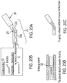
FIGS. 20A, 20B, 20C, 20D schematically illustrate a side view of another embodiment of a clip with arms having two part articulated together through joints in accordance with aspects of the present disclosure. - Throughout all of the drawings, dimensions of respective constituent elements are appropriately adjusted for clarity. For ease of viewing, in some instances only some of the named features in the figures are labeled with reference numeral.
- Clips of the present disclosure are useful in therapeutic procedures of a patient such as to prevent tissue bleeding, closing perforations and hemostasis, and suture contraction of the inner wound, marking lesions and traction (mucosal elevation) and other surgical procedures. The term "patient," as used herein, comprises any and all organisms and includes the term "subject." A patient can be a human or an animal.
- Generally clips for grabbing tissue of a patient are actuated by a clip operation tool. Such a tool actuates the clip by an operational wire typically housed in a flexible tube in which the operational wire can advance and retract longitudinally in the flexible tube by operating an handle of the tool. References herein to the term "distal" are to a direction away from the operating handle, while references to the term "proximal" are to a direction towards the operating handle. Clip operation tools such as those described in
U.S. Patent Nos. 8,480,685 and9,949,740 - Various embodiments and aspects of a clip according to the present disclosure will be described with references to
FIGS. 1 through 20 . - As shown in
FIGS. 1A-1D , aclip 10 for gripping biological tissue of a patient has afirst arm 12, which has afirst claw 12a at a distal end of thefirst arm 12, and asecond arm 13, which has asecond claw 13a at a distal end of thesecond arm 13. As further illustrated,first claw 12a andsecond claw 13a face each other andfirst arm 12 andsecond arm 13 are configured to move in a reciprocal direction R toward and away from each other to close and open the clip. The first and second claws can be on the same or approximately the same plane such that when the arms close, the claws contact each other. - Clips of the present disclosure advantageously include one or more anchors protruding from the first arm and/or the second arm. An anchor as used herein includes a structure that can attach to tissue of a patient upon contact with minimal force and can include, for example, a protrusion, hook, barb, spike, etc. The one or more anchors protrude from their respective arms in a direction other than the direction that the first and second arms are configured to move toward each other to close the clip. For example, the anchor can protrude in a direction divergent from a claw or in a direction that is orthogonal to a plane defined by the first and second arm (in a vertical direction relative to an arm) or protruding at any other direction other than the direction the first and second arms are configured to move toward each other to close the clip.
- As further illustrated by
FIGS. 1A-1D ,first arm 12 includes afirst anchor 14a on an outer surface offirst arm 12 protruding in a direction divergent fromfirst claw 12a and asecond arm 13 includes asecond anchor 14b on an outer surface thereon protruding in a direction divergent fromsecond claw 13a.Clip 10 can deploy from within a pipe (also referred to herein as a pressing tube) 16 which can be coupled to aflexible tube 18. During operation,arms FIGS. 1C and 1D , can be closed by actuating an operational wire (not shown) coupled to the clip to slidably move the clip proximally and distally in the pipe. The operational wire can advance and retract longitudinally in the flexible tube (not shown) by operating a handle of the tool (not shown). Slidably moving the clip distally and proximally opens and closes the clip by moving the arms and claws toward and away from each other. In some embodiments, once the clip is retracted in a pressing tube, the clip can be locked from opening. - As illustrated in
FIGS. 1C-1D , an advantage of clips of the present disclosure is that they can attach to tissue even when the approach A of the clip is not perpendicular to the tissue, e.g.FIG. 1C illustrates a perpendicular approach whileFIG. 1D illustrates a tangential approach. During anon-perpendicular approach anchor 14b onarm 13 can catch tissue T near a defect D. When closing the clip after the anchor catches tissue, the claw and arm can elevate the tissue so that the claws of the arms can more readily grasp the tissue. In addition, after an anchor catches tissue, the clip can be rotated to further grasp the tissue in the claw of the arm with the anchor attached to the issue. Advantageously, one or more anchors on outer surfaces of arms of clips of the present disclosure can prevent the distal end of an arm of a clip from slipping during a tangential approach to tissue (FIG. 1D ). -
FIGS. 2A through 6B illustrate different aspects of clips of the present disclosure and different ways to mitigate contact of the anchors with other parts of a clip tool or endoscope. For example,FIGS. 2A-2E show a cover that can shield anchors of the clip. InFIGS. 2A-2B acover 21 is attached to pressing tube (pipe) 16 and extending distally from pressingtube 16.Clip 10 can close (FIG. 2B ) by slidably retracting in pressingtube 16. The cover can extend sufficiently distally to shield one or more anchors on outer surfaces of the arms when the clip is retracted in the pressing tube. As shown inFIG. 2B , cover 21 extends distally sufficiently to shieldanchors clip 10 is retracted in pressingtube 16. -
FIGS. 2C-2E illustrate different attachment locations for a cover that can shield anchors of the clip. For example,FIG. 2C showscover 21 attached tosheath 18.FIGS. 2D-2E show howcover 21 can be attached to aconnection member 29 orwire 27.FIG. 2D shows the clip in an open state with theanchors FIG. 2E shows the clip in a closed state with the anchors shielded bycover 21. Irrespective of the location of attachment, the cover extends sufficiently distally to shield the anchors when the clip is retracted in the pressing tube.Cover 21 can be made of a plastic or other elastic material or a metal and can be attached by an adhesive or weld. -
FIGS. 3A-3C and4A-4C show flexible anchors that can protrude through slits in arms of a clip after the clip is opened. As illustrated inFIG. 3A , anchors 34a and 34b can be shielded by inner surfaces offirst arm 32 andsecond arm 33 ofclip 30 when the clip is in the closed state (FIG. 3A ). Theanchors flexible members clip 30 is in an opened state as illustrated inFIGS. 3B and 3C ,anchor 34a protrudes throughslit 35 infirst arm 32 ofclip 30.Anchor 34b similarly protrudes through a slit insecond arm 33 whenclip 30 is in an open state, which is not illustrated for convenience. In this way, the anchors can be shielded prior to deploying the clip, such as deployingclip 30 from pressingtube 16. - In separate embodiments,
FIGS. 4A-4H show flexible anchors that can protrude through slits in arms of a clip after the clip is opened. In particular, anchors 44a and 44b can be retracted toward first andsecond arms 42 and 43, respectively, when theclip 40 moves toward a closed state (FIG. 4B-4C ). Theanchors flexible members clip 40 is in an opened state as illustrated inFIG. 4A ,anchor 44a protrudes throughslit 45 infirst arm 42 ofclip 40 byflexible member 41a.Anchor 44b similarly protrudes through a slit in second arm 43 whenclip 40 is in an open state, which is not illustrated for convenience. In this way, the anchors can be brought toward the arms of the clip when the clip is retracted in pressingtube 16. - As further illustrated in
FIGS 4D-4H , clips and the flexible members can be in a closed state when inserted in a tool such as an endoscope (FIGS. 4E and4F ). Since the clip arms and flexible members are bias toward an open state, the clip arms and flexible members open in an operation of exiting a channel of the tool (FIGS. 4D and4G ). In operation, a handle (not shown) connected to a proximal end of wire (not shown) operates the wire 47 to retract theclip 40 in apressing pipe 16 to close the clip arms. Certain clip devices can include aconnection member 49 to engage and release a pressing tube from the sheath 18 (FIG. 4H ). Such devices include a connection member to engage and disengage a distal end of the clip from the wire. In addition, the connection member can include internal engaging and disengaging elements. The flexible members can be connected to the wire or connection member and retracted in the pressing tube (FIG. 4H ). - In separate embodiments,
FIGS. 5A and 5B showclip 50 for gripping biological tissue of a patient havingfirst arm 12, which has afirst claw 12a at a distal end of thefirst arm 12 and asecond arm 13, which has asecond claw 13a at a distal end of thesecond arm 13. As further illustrated,first claw 12a andsecond claw 13a face each other andfirst arm 12 andsecond arm 13 are configured to move in a reciprocal direction R toward and away from each other to close and open the clip. As further illustrated in the figures,first arm 12 includes ananchor 14a protruding from thefirst arm 12 in a direction divergent fromfirst clam 12a and asecond arm 13 includes asecond anchor 14b protruding from thesecond arm 13 in a direction divergent fromsecond claw 13a.Clip 50 can deploy from within apressing tube 16 to an open state (FIG. 5A ). When in a closed state (FIG. 5B ), the clip forms a width -W defined by the distance between the distal ends of the anchors, which is less than a width of pressingtube 16 or less than a width of a channel in atreatment tool 51 such as a channel in an endoscope so that the anchors protruding from thearms - In another embodiment,
FIGS. 6A and 6B show aclip 10 havingfirst arm 12, which has afirst claw 12a at a distal end of thefirst arm 12 and asecond arm 13, which has asecond claw 13a at a distal end of thesecond arm 13. As further illustrated,first claw 12a andsecond claw 13a face each other andfirst arm 12 andsecond arm 13 are configured to move in a direct toward each other to close the clip. In this embodiment,claws anchor 64a onfirst arm 12 and includes ananchor 64b onsecond arm 13 in which both anchors protrude in a direction that is orthogonal to a plane formed by first andsecond arm tube 66 has an opening, e.g., diameter D, sufficiently large to allow the anchors to enter the tube when the clip is retracted in the pressing tube.FIG. 6B shows the anchors 64 in pressingtube 66 when the clip is retracted in the pressing tube and the clip is in a closed state. - It should be noted that the arms, claws and anchors can have suitable forms, such as the form of a wire (as in the embodiments illustrated in, e.g.,
FIGS. 1A to 1D , or as the form of a ribbon (as in the embodiments illustrated in, e.g.,FIGS. 6A and 6B ), or can have a mixed form, such as one of the arms and claws in the form of a ribbon and the anchors in the form of a wire. -
FIGS. 7 through 8 illustrate other aspects of anchors that can be included on arms of clips. In particular,FIGS. 7A- 7C show clip 70 for gripping biological tissue T of a patient has afirst arm 12, which has afirst claw 12a at a distal end of thefirst arm 12 and asecond arm 13, which has asecond claw 13a at a distal end of thesecond arm 13.First claw 12a andsecond claw 13a face each other. As further illustrated,first arm 12 includes afirst anchor 74a on an outer surface offirst arm 12 protruding in a direction divergent fromfirst clam 12a and asecond arm 13 includes asecond anchor 74b on an outer surface thereon protruding in a direction divergent fromsecond claw 13a. In this example, first and second anchors, 74a and 74b, are made of a bioadsorbable material. In this way, after the anchors attach to the tissue T, they can eventually dissolve in the tissue and be removed from the clip (FIG. 7C ). Such anchors made of bioadsorbable can be initially attached to the clip arms by an adhesive, such as a bioadsorbable adhesive. -
FIGS. 8-11 show anchors that protrude in a direction that is orthogonal to a plane defined by the first and second arm. In particular,FIGS. 8 and10 show clip 10 for gripping biological tissue T of a patient including afirst arm 12, which has afirst claw 12a at a distal end of thefirst arm 12, and asecond arm 13, which has asecond claw 13a at a distal end of thesecond arm 13, in whichfirst claw 12a andsecond claw 13a face each other andfirst arm 12 andsecond arm 13 are configured to move toward each other to close the clip. InFIG. 8A ,first arm 12 includes afirst anchor 84a in which the anchor protrude from the first arm in a direction that is orthogonal to a plane P defined by the first and second arm. As shown in the figure, the arms can form a plane with x and y coordinates and the anchor can protrude in the z coordinate. InFIG. 10A ,first arm 12 includes afirst anchor 104a in which the anchor protrude from the first arm in a direction that is orthogonal to a plane defined by the first and second arm andsecond arm 13 includes asecond anchor 104b in which the anchor protrude from the second arm in a direction that is orthogonal to a plane defined by the first and second arm.Anchors FIGS. 8B ,10B ) to elevate when the arms approach each other (81, 101 inFIG. 8C ,FIG. 10C , presectively) which facilitates grasping the tissue in the arms. -
FIGS. 9A-9C illustrate clips having more than one anchor per arm, and/or in which anchors protrude in different directions from each other. In particular,FIG. 9A showsfirst arm 12 with two anchors. Afirst anchor 94a protrudes fromfirst arm 12 in a direction that is orthogonal to a plane defined by the first and second arm, asecond anchor 94c which protrudes fromfirst arm 12 in a direction that is orthogonal to a plane defined by the first and second arm but opposite offirst anchor 94a.Second arm 13 also has two anchors. Athird anchor 94b protrudes fromsecond arm 13 in a direction that is orthogonal to a plane defined by the first and second arm, afourth anchor 94d which protrudes fromsecond arm 13 in a direction that is orthogonal to a plane defined by the first and second arm but opposite ofthird anchor 94c.FIG. 9B showsfirst arm 12 with twoanchors second arm 13 with athird anchor 94d.FIG. 9C shows each of the arms of the clips having oneanchor -
FIGS. 11A-11B and11C illustrate anchors configured to rotate into the plane of the arms when the clip is retracted in a pressing tube. For example and with reference toFIGS. 11A-11B , first andsecond anchors second arms example pins pressing tube 116 and an edge of the pressing tube contacts the anchors. -
FIG. 11C shows another structure configured to rotate the anchor into the plane of the arms of a clip when the arms are slidable retracted or extended from a pressing tube. As shown,anchor 114 is formed integral to cliparm 13 and biased in an open state but when retracted inpressing pipe 116 is in a closed state. By this structure, no pins are needed on the arms of the clips to include anchors which can rotate toward the plane defined by the arms when the clip is retracted into thepressing tube 116. Instead, the anchors have a spring open bias and pops-out of the pressing tube upon extended distally from the tube. -
FIGS. 12-13 illustrate clips having anchors that can be more easily identified when the clips are is use. For example,FIGS. 12A and 12B showfirst arm 12 andsecond arm 13 with amarker 121 on the respective arms which identifies the location offirst anchor markers markers 121 on the arms of the clip can be caused by a fluorescent marker, color, symbol, texture on the arm such as a roughness, etc. or equivalent on the arm at the location of the anchor. -
FIGS. 13A and 13B illustrate clips with claws that have a gap or in which a width of a claw is greater or less than a width of the anchor so that the anchors can be more readily observed when the clip is in use. For example,FIGS. 13A- 13B show clip 10 with first andsecond arms second claws second anchors claws claws FIG. 13A showsfirst claw 12a with a gap which facilitates observinganchor 134a andsecond clam 13a has a gap which facilitates observinganchor 134b. -
FIGS. 14-20 schematically illustrate clip arms in accordance with the present disclosure that can further advantageously apply a vertical force to tissue when the clip is tangential thereto and can bend to facility placing multiple clips in close proximity to each other. For example,FIGS. 14A and 14B show a side view ofclip 10 showingfirst arm 12 withanchor 144 protruding from thefirst arm 12 in a vertical direction from the longitudinal direction of the first arm. In this example,anchor 144 is in the shape of a hook and in a direction that is orthogonal to a plane defined by the first and second arm of the clip, which allows the clip to be placed vertically on the tissue. Afteranchor 144 attaches to tissue T, the clip can be rotated 141 which results in a vertical force on the tissue. Another advantage of anchors on clips as set forth in the present disclosure is that such clips can be pressed firmly against the mucosa allowing more tissue to be inserted between the claws and more tissue grasped by the clip. - In certain embodiments, clips of the present disclosure can be disconnected from a surgical tool and clipped on tissue of a patient. To facilitate placing clips adjacent to each other, the clip arms can be configured to bend. A shown in the side views of
FIGS 15A and 15B , aclip 150a can be configured to be released from a surgical tool after the clip is attached to tissue of a patient. However, placement of asecond clip 150b is somewhat limited due to the proximal end of the clip and any member attached to the proximal end of the clip such as apressing tube 156. In this example,clip 150c has afirst arm 152 and second arm (not shown) with afirst anchor 154 onfirst arm 152 andpressing tube 156. As shown,clip 150c includes a bending portion ormember 151 along the clip. In this way, clips having anchors andarms -
FIGS. 16-20 schematically illustrate various structural features which configure a clip arm to bend. For example,FIGS. 16A and 16C show clip 160 having afirst arm 162 which includes amember 161 with high elasticity. The second arm ofclip 160 would also have a member with high elasticity, but is not illustrates in the side view ofFIG. 16 . The clip arms are bias to be in a bent state such that when the clip is loaded inpressing tube 166, the clip arms are in a straight position L, but when deployed from pressingtube 166,clip arm 162 bends as shown in the unloaded state U. As an alternative, or in addition to, an elastic member, a clip arms can have one or more springs to bias the clip arms in a bent state. When such a clip is placed in a channel of anendoscope 165, the arms would be in a straight state but when deployed from the channel, the arms would bend (FIG. 16B ). InFIG. 17A ,clip arm 172 includes anotch 171 which can relieve stress when the arm is bent. - Other structures that could be used to configure the arms of clips of the represent disclosure to bend are illustrated in
FIGS. 18-20 . InFIGS. 18A and 18B , clip arm 182 includes twoparts FIGS. 19A - 19C illustrate locking configurations of an arm of a clip configured to bend.FIG. 19A showsclip arm 192 comprised of two articulatingparts Part 192b can have apin 195a that moves along agrove 195b when the arm is moving to a bent position. The pin can pass over aprojection 195c in thegrove 195b to lock the arm in the bent state.FIGS. 19B-19C show clip arm 195 comprised of two articulatingparts inner part 195a ofarm 195 has aconcavity 197a and theouter part 195b ofarm 195 has aconvexity 197b such that when theouter part 195b ofarm 195 rotates to position the arm in a bend state theconcavity 197a fits inconvexity 197b as shown in the cross sectional view ofarm 195. -
FIGS. 20A - 20D illustrate clip arms articulated together through springs. InFIG. 20A , arm 202 includes twoparts spring 201. The clip arm is biased to be in a bent state such that when the clip is loaded inpressing tube 206, the clip arm is in a straight position L, but when deployed from pressingtube 206, clip arm 202 bends as shown in the unloaded state U inFIG. 20B . When such a clip is placed in a channel of anendoscope 205, the arms of the clip would be in a straight state but when deployed from the channel, the arms would bend (FIG. 20C and 20D ). - In other examples, the clip arms can be made of a shape memory alloy, such as Nitinol, and are in the straightened or bent configuration based on stress state or temperature.
- While the claimed invention has been described in detail and with reference to specific embodiments thereof, it will be apparent to one of ordinary skill in the art that various changes and modifications can be made to the claimed invention. All features described above with reference to a specific embodiment can be combined as required and hence also be present other embodiments. Thus, for example, those skilled in the art will recognize, or be able to ascertain, using no more than routine experimentation, numerous equivalents to the specific substances and procedures described herein. Such equivalents are considered to be covered by the following claims.
Claims (15)
- A clip (10; 30; 40; 50; 70; 150a, 150b, 150c, 150d; 160) for gripping tissue having a first arm (12; 32; 42; 152; 162; 172; 182; 192; 202) with a first claw (12a) at a distal end of the first arm (12; 32; 42; 152; 162; 172; 182; 192; 202), and a second arm (13; 33; 43) with a second claw (13a) at a distal end of the second arm (13; 33; 43), wherein the first arm (12; 32; 42; 152; 162; 172; 182; 192; 202) and the second arm (13; 33; 43) are configured to move in a direction toward each other to close the clip (10; 30; 40; 50; 70; 150a, 150b, 150c, 150d; 160);
wherein the clip (10; 30; 40; 50; 70; 150b, 150c, 150d; 160) includes a first anchor (14a; 34a; 44a; 64a; 74a; 84a; 94a, 94b; 104a; 114; 114a; 124a; 134a; 144; 154) protruding from the first arm (12; 32; 42; 152; 162; 172; 182; 192; 202) in a direction other than the direction that the first arm (12; 32; 42; 152; 162; 172; 182; 192; 202) and the second arm (13; 33; 43; 150b, 150c, 150d) are configured to move toward each other to close the clip (10; 30; 40; 50; 70; 150a, 150b, 150c, 150d; 160). - The clip of claim 1, further comprising
a second anchor (14b; 34b; 44b; 64b; 74b; 84b; 94c, 94d; 104b; 114b; 124b; 134b) protruding from the second arm (13; 33; 43) in a direction other than the direction that the first arm (12; 32; 42; 152; 162; 172; 182; 192; 202) and the second arm (13; 33; 43) are configured to move toward each other to close the clip (10; 30; 40; 50; 70; 50a, 150b, 150c, 150d; 160). - The clip of claim 1 or 2, further comprisinga pressing tube (16; 66; 116; 156; 206) in which the clip (10; 30; 40; 50; 70; 150b, 150c, 150d; 160) can slidably retract to close the clip (10; 30; 40; 50; 70; 150a, 150b, 150c, 150d; 160); and/ora cover (21) shielding at least one of the first anchor (14a) and the optional second anchor (14b) when the clip (10) is retracted in the pressing tube (16).
- The clip of anyone of claims 1 to 3,wherein the first anchor (34a; 44a) protrudes through a slit (35; 45) in the first arm (32; 42); and/orwherein the optional second anchor (34b; 44b) protrudes through a slit in the second arm (33; 43).
- The clip of claim 2 or anyone of claims 3 or 4 when depending on claim 2, wherein the clip (10; 50), when in a closed state, forms a width (W) defined by opposite ends of the first and second anchors (14a, 14b; 64a, 64b), which is less than a width of a pressing tube (16; 66) or less than a width of a channel in a treatment tool (51).
- The clip of claim 3 or anyone of claims 4 or 5 when depending on claim 3, wherein the pressing tube (16; 66) has an opening that allows at least one of the first anchor (14a; 64a; 84a) and the optional second anchor (14b; 64b) to enter the pressing tube (16; 66; 156) when the clip (10; 50) is retracted in the pressing tube (16; 66).
- The clip of anyone of claims 1 to 6,wherein the first anchor (84a; 94a; 104a; 114a) protrudes from the first arm (12) in a direction that is orthogonal to a plane defined by the first and second arm (12, 13); and/orwherein the optional second anchor (84b; 94b; 104b; 114b) protrudes from the second arm (13) and in a direction that is orthogonal to a plane defined by the first and second arm (12, 13). .
- The clip of anyone of claims 1 to7,wherein the first anchor (114a) is configured to rotate toward a plane defined by the first and second arm (12, 13); and/orwherein the optional second anchor (114b) is configured to rotate toward a plane defined by the first and second arm (12, 13).
- The clip of anyone of claims 1 to 8,wherein the first anchor (14a; 34a; 44a; 64a; 74a; 84a; 94a, 94b; 104a; 114; 114a; 124a; 134a; 144; 154) protrudes from the first arm (12) in a direction divergent from the first claw (12a); and/orwherein the first claw (12a) has a gap so that the first anchor (134a) can be seen through the gap of the first claw (12a); and/orwherein the first anchor (134a) has a width that is smaller or larger than a width of the first claw (12a); and/orwherein the optional second anchor (74b; 134b) protrudes from the second arm (13) in a direction divergent from the second claw (13a); and/orwherein the second claw (13a) has a gap so that the second anchor (134b) can be seen through the gap of the second claw (13a); and/orwherein the second anchor (134b) has a width that is smaller or larger than a width of the second claw (13a).
- The clip of anyone of claims 1 to 9,
wherein at least one of the first anchor (144) and the optional second anchor is in the form of a hook. - The clip of anyone of claims 1 to 10,
wherein the first arm (12) has a first marker (121a) which identifies the location of the first anchor (124a). - The clip of anyone of claims 1 to 11, wherein at least one of the first arm (12; 32; 42; 152; 162; 172; 182; 192; 202) and the second arm (13; 33; 43) is configured to bend.
- The clip of claim 12, wherein at least one of the first arm (192) and the second arm (13) is configured to lock in a bent state.
- The clip of anyone of claims 1 to 13, wherein the second arm (13) includes the optional second anchor.
- The clip of anyone of claims 1 to 14, wherein at least one of the first anchor and the optional second anchor is made of a bioadsorbale material.
Priority Applications (1)
| Application Number | Priority Date | Filing Date | Title |
|---|---|---|---|
| EP25180708.7A EP4588446A3 (en) | 2020-10-16 | 2021-10-08 | Clip for endoscope |
Applications Claiming Priority (1)
| Application Number | Priority Date | Filing Date | Title |
|---|---|---|---|
| US202063092981P | 2020-10-16 | 2020-10-16 |
Related Child Applications (2)
| Application Number | Title | Priority Date | Filing Date |
|---|---|---|---|
| EP25180708.7A Division EP4588446A3 (en) | 2020-10-16 | 2021-10-08 | Clip for endoscope |
| EP25180708.7A Division-Into EP4588446A3 (en) | 2020-10-16 | 2021-10-08 | Clip for endoscope |
Publications (2)
| Publication Number | Publication Date |
|---|---|
| EP3984472A1 true EP3984472A1 (en) | 2022-04-20 |
| EP3984472B1 EP3984472B1 (en) | 2025-07-09 |
Family
ID=78085849
Family Applications (3)
| Application Number | Title | Priority Date | Filing Date |
|---|---|---|---|
| EP21201423.7A Pending EP3984471A1 (en) | 2020-10-16 | 2021-10-07 | Bendable clip device |
| EP25180708.7A Pending EP4588446A3 (en) | 2020-10-16 | 2021-10-08 | Clip for endoscope |
| EP21201671.1A Active EP3984472B1 (en) | 2020-10-16 | 2021-10-08 | Clip for endoscope |
Family Applications Before (2)
| Application Number | Title | Priority Date | Filing Date |
|---|---|---|---|
| EP21201423.7A Pending EP3984471A1 (en) | 2020-10-16 | 2021-10-07 | Bendable clip device |
| EP25180708.7A Pending EP4588446A3 (en) | 2020-10-16 | 2021-10-08 | Clip for endoscope |
Country Status (5)
| Country | Link |
|---|---|
| US (4) | US12114865B2 (en) |
| EP (3) | EP3984471A1 (en) |
| JP (5) | JP7426364B2 (en) |
| CN (3) | CN114376654A (en) |
| WO (1) | WO2022080474A1 (en) |
Families Citing this family (5)
| Publication number | Priority date | Publication date | Assignee | Title |
|---|---|---|---|---|
| JPWO2024128084A1 (en) * | 2022-12-16 | 2024-06-20 | ||
| WO2024162800A1 (en) * | 2023-02-02 | 2024-08-08 | 고려대학교 산학협력단 | Endoscope clip using shape memory alloy |
| JPWO2024257386A1 (en) * | 2023-06-16 | 2024-12-19 | ||
| WO2026033792A1 (en) * | 2024-08-09 | 2026-02-12 | オリンパスメディカルシステムズ株式会社 | Clip device |
| WO2026062783A1 (en) * | 2024-09-18 | 2026-03-26 | オリンパスメディカルシステムズ株式会社 | Clip device |
Citations (8)
| Publication number | Priority date | Publication date | Assignee | Title |
|---|---|---|---|---|
| EP2127606A1 (en) * | 2007-01-26 | 2009-12-02 | Olympus Medical Systems Corporation | Holding device and holding tool |
| US8480685B2 (en) | 2004-12-07 | 2013-07-09 | Olympus Corporation | Endo-therapy product system and cartridge including treatment device |
| JP2015008858A (en) | 2013-06-28 | 2015-01-19 | 日本ゼオン株式会社 | Endoscope clip |
| US9949740B2 (en) | 2013-05-07 | 2018-04-24 | Olympus Corporation | Clip unit |
| US20190150929A1 (en) * | 2017-11-15 | 2019-05-23 | United States Endoscopy Group, Inc. | Clip and clip assembly |
| WO2019189864A1 (en) * | 2018-03-30 | 2019-10-03 | 日本ゼオン株式会社 | Indwelling clip |
| WO2019207585A1 (en) * | 2018-04-25 | 2019-10-31 | Endomatic Ltd. | Suturing clip |
| WO2020136906A1 (en) * | 2018-12-28 | 2020-07-02 | オリンパス株式会社 | Ligation device and engaging method |
Family Cites Families (60)
| Publication number | Priority date | Publication date | Assignee | Title |
|---|---|---|---|---|
| US5409498A (en) * | 1992-11-05 | 1995-04-25 | Ethicon, Inc. | Rotatable articulating endoscopic fastening instrument |
| US5620452A (en) | 1994-12-22 | 1997-04-15 | Yoon; Inbae | Surgical clip with ductile tissue penetrating members |
| US5904647A (en) | 1996-10-08 | 1999-05-18 | Asahi Kogyo Kabushiki Kaisha | Treatment accessories for an endoscope |
| US6398791B1 (en) | 1999-06-11 | 2002-06-04 | Scimed Life Systems Inc | Variable composite sheath with interrupted sections |
| JP4472217B2 (en) * | 2000-10-16 | 2010-06-02 | オリンパス株式会社 | Biological tissue clip device |
| US20020138086A1 (en) | 2000-12-06 | 2002-09-26 | Robert Sixto | Surgical clips particularly useful in the endoluminal treatment of gastroesophageal reflux disease (GERD) |
| US6716226B2 (en) * | 2001-06-25 | 2004-04-06 | Inscope Development, Llc | Surgical clip |
| US6544274B2 (en) | 2001-05-02 | 2003-04-08 | Novare Surgical Systems, Inc. | Clamp having bendable shaft |
| US7094245B2 (en) | 2001-10-05 | 2006-08-22 | Scimed Life Systems, Inc. | Device and method for through the scope endoscopic hemostatic clipping |
| JP4109030B2 (en) | 2002-07-19 | 2008-06-25 | オリンパス株式会社 | Biological tissue clip device |
| US7727247B2 (en) * | 2002-08-21 | 2010-06-01 | Olympus Corporation | Living tissue ligation device |
| JP4109069B2 (en) * | 2002-10-01 | 2008-06-25 | オリンパス株式会社 | Biological tissue ligation device |
| JP4412943B2 (en) * | 2003-08-20 | 2010-02-10 | Hoya株式会社 | Endoscopic clip device |
| US7052489B2 (en) | 2003-12-05 | 2006-05-30 | Scimed Life Systems, Inc. | Medical device with deflecting shaft and related methods of manufacture and use |
| US7361180B2 (en) * | 2004-05-07 | 2008-04-22 | Usgi Medical, Inc. | Apparatus for manipulating and securing tissue |
| JP2006158668A (en) * | 2004-12-07 | 2006-06-22 | Olympus Corp | Treatment instrument for endoscope |
| JP2006296781A (en) | 2005-04-21 | 2006-11-02 | Olympus Medical Systems Corp | Endoscopic treatment tool |
| US7963288B2 (en) | 2005-05-03 | 2011-06-21 | Hansen Medical, Inc. | Robotic catheter system |
| JP4935040B2 (en) * | 2005-09-30 | 2012-05-23 | 住友ベークライト株式会社 | Endoscope clip |
| JP2007136128A (en) | 2005-11-17 | 2007-06-07 | River Seiko:Kk | Endoscopic clip device |
| JP4716513B2 (en) * | 2006-11-09 | 2011-07-06 | Hoya株式会社 | Endoscopic clip device |
| US8142450B2 (en) | 2007-03-13 | 2012-03-27 | Longevity Surgical, Inc. | Methods for reducing gastric volume |
| US8162959B2 (en) | 2007-05-03 | 2012-04-24 | Boston Scientific Scimed, Inc. | Single stage hemostasis clipping device |
| US9393093B2 (en) | 2008-02-18 | 2016-07-19 | Covidien Lp | Clip for implant deployment device |
| DE202009019015U1 (en) * | 2008-06-19 | 2015-08-21 | Boston Scientific Scimed, Inc. | Hemostatic clamping device |
| US20090318937A1 (en) * | 2008-06-24 | 2009-12-24 | Fujifilm Corporation | Clip coupling method and multiple clip package |
| JP2010213990A (en) * | 2009-03-18 | 2010-09-30 | Fujifilm Corp | Connection clip package, and clip loading method |
| US8460319B2 (en) * | 2010-01-11 | 2013-06-11 | Anulex Technologies, Inc. | Intervertebral disc annulus repair system and method |
| US8403945B2 (en) * | 2010-02-25 | 2013-03-26 | Covidien Lp | Articulating endoscopic surgical clip applier |
| WO2012005964A1 (en) * | 2010-06-28 | 2012-01-12 | Boston Scientific Scimed, Inc. | Scope protection for endoscopic devices |
| US8968337B2 (en) * | 2010-07-28 | 2015-03-03 | Covidien Lp | Articulating clip applier |
| BR112013003255A8 (en) * | 2010-08-10 | 2017-10-17 | Cook Medical Tech Llc Us | clamp device and delivery and deployment methods |
| JP2012065835A (en) * | 2010-09-22 | 2012-04-05 | Fujifilm Corp | Ligature device and clip unit used therein |
| US20120078372A1 (en) * | 2010-09-23 | 2012-03-29 | Thomas Gamache | Novel implant inserter having a laterally-extending dovetail engagement feature |
| JP5781347B2 (en) | 2011-03-28 | 2015-09-24 | 日本ゼオン株式会社 | Endoscopic treatment tool |
| US10154842B2 (en) * | 2011-05-04 | 2018-12-18 | Boston Scientific Scimed, Inc. | Through the scope tension member release clip |
| US20130023925A1 (en) | 2011-07-20 | 2013-01-24 | Tyco Healthcare Group Lp | Articulating Surgical Apparatus |
| US20130158566A1 (en) | 2011-12-15 | 2013-06-20 | Boston Scientific Scimed, Inc. | Rotational mechanism for endoscopic devices |
| US20130226199A1 (en) * | 2012-02-28 | 2013-08-29 | Boston Scientific Scimed, Inc. | Omnidirectional closure clip |
| US8992547B2 (en) * | 2012-03-21 | 2015-03-31 | Ethicon Endo-Surgery, Inc. | Methods and devices for creating tissue plications |
| JP2013255756A (en) | 2012-06-14 | 2013-12-26 | Fujifilm Corp | Treatment instrument for endoscope |
| US20160157703A1 (en) * | 2013-06-18 | 2016-06-09 | The Hospital For Sick Children | Tissue gripping device |
| US9427232B2 (en) | 2013-11-08 | 2016-08-30 | C.R. Bard, Inc. | Surgical fastener |
| EP3193739A2 (en) * | 2014-08-21 | 2017-07-26 | Boston Scientific Scimed, Inc. | Anchors and cinching for tissue opposition |
| JP6700572B2 (en) | 2015-01-08 | 2020-05-27 | 日本ゼオン株式会社 | Clip device for endoscope |
| FR3032607B1 (en) * | 2015-02-13 | 2020-10-23 | Institut Hospitalo Univ De Chirurgie Mini Invasive Guidee Par Limage | SURGICAL CLIP PRESENTING TWO MOBILE BRANCHES CONNECTED BY A CROSS-LINK ZONE |
| JP6649830B2 (en) * | 2016-03-29 | 2020-02-19 | 小林 真 | Endoscope treatment tool |
| JP2017192513A (en) * | 2016-04-19 | 2017-10-26 | 株式会社新興セルビック | Method for producing synthetic resin blood vessel clip and synthetic resin blood vessel clip |
| US20170340443A1 (en) | 2016-05-24 | 2017-11-30 | Edwards Lifesciences Corporation | Posterior mitral valve leaflet approximation |
| US11206972B2 (en) | 2016-06-06 | 2021-12-28 | 3Nt Medical Ltd. | Modular body cavity access system |
| JP2018061672A (en) * | 2016-10-12 | 2018-04-19 | 日本ゼオン株式会社 | Indwelling clip |
| CN109922743B (en) * | 2016-11-22 | 2021-12-14 | 波士顿科学有限公司 | Hemostatic Reloadable Clip Release Mechanism |
| CN108567462B (en) * | 2017-03-07 | 2021-05-11 | 祝建红 | hemostatic clip |
| WO2019008632A1 (en) | 2017-07-03 | 2019-01-10 | オリンパス株式会社 | Control device, treatment system, and treatment tool |
| EP3763309B1 (en) | 2018-03-07 | 2023-11-08 | FUJIFILM Corporation | Treatment tool, endoscope device, endoscope system |
| US11033279B2 (en) | 2018-04-24 | 2021-06-15 | Covidien Lp | Ligation clip with retention features |
| CN112969418B (en) * | 2018-11-09 | 2024-05-10 | 奥林巴斯株式会社 | Clamp unit and endoscope clamp |
| CN210077721U (en) | 2018-12-14 | 2020-02-18 | 杭州市第一人民医院 | A steerable curved biopsy forceps |
| US11076862B2 (en) * | 2018-12-28 | 2021-08-03 | Olympus Corporation | Clip unit, medical instrument, and attaching method of medical instrument |
| WO2020189666A1 (en) * | 2019-03-18 | 2020-09-24 | 国立大学法人熊本大学 | Organ resection stump fixing clip |
-
2021
- 2021-10-07 JP JP2021165768A patent/JP7426364B2/en active Active
- 2021-10-07 JP JP2021165771A patent/JP7553420B2/en active Active
- 2021-10-07 EP EP21201423.7A patent/EP3984471A1/en active Pending
- 2021-10-08 EP EP25180708.7A patent/EP4588446A3/en active Pending
- 2021-10-08 WO PCT/JP2021/038151 patent/WO2022080474A1/en not_active Ceased
- 2021-10-08 EP EP21201671.1A patent/EP3984472B1/en active Active
- 2021-10-11 US US17/498,062 patent/US12114865B2/en active Active
- 2021-10-11 CN CN202111181510.XA patent/CN114376654A/en active Pending
- 2021-10-11 US US17/498,064 patent/US11931043B2/en active Active
- 2021-10-12 CN CN202411224240.XA patent/CN119112284A/en active Pending
- 2021-10-12 CN CN202111186087.2A patent/CN114376655B/en active Active
-
2023
- 2023-05-15 JP JP2023080358A patent/JP2023091094A/en active Pending
-
2024
- 2024-01-12 US US18/411,596 patent/US20240148389A1/en active Pending
- 2024-01-22 JP JP2024007521A patent/JP7791223B2/en active Active
- 2024-08-21 US US18/810,632 patent/US20240407788A1/en active Pending
-
2025
- 2025-12-10 JP JP2025244599A patent/JP2026031756A/en active Pending
Patent Citations (8)
| Publication number | Priority date | Publication date | Assignee | Title |
|---|---|---|---|---|
| US8480685B2 (en) | 2004-12-07 | 2013-07-09 | Olympus Corporation | Endo-therapy product system and cartridge including treatment device |
| EP2127606A1 (en) * | 2007-01-26 | 2009-12-02 | Olympus Medical Systems Corporation | Holding device and holding tool |
| US9949740B2 (en) | 2013-05-07 | 2018-04-24 | Olympus Corporation | Clip unit |
| JP2015008858A (en) | 2013-06-28 | 2015-01-19 | 日本ゼオン株式会社 | Endoscope clip |
| US20190150929A1 (en) * | 2017-11-15 | 2019-05-23 | United States Endoscopy Group, Inc. | Clip and clip assembly |
| WO2019189864A1 (en) * | 2018-03-30 | 2019-10-03 | 日本ゼオン株式会社 | Indwelling clip |
| WO2019207585A1 (en) * | 2018-04-25 | 2019-10-31 | Endomatic Ltd. | Suturing clip |
| WO2020136906A1 (en) * | 2018-12-28 | 2020-07-02 | オリンパス株式会社 | Ligation device and engaging method |
Also Published As
| Publication number | Publication date |
|---|---|
| EP4588446A3 (en) | 2025-09-10 |
| JP7791223B2 (en) | 2025-12-23 |
| US20240148389A1 (en) | 2024-05-09 |
| CN114376655A (en) | 2022-04-22 |
| JP2024032823A (en) | 2024-03-12 |
| EP4588446A2 (en) | 2025-07-23 |
| US11931043B2 (en) | 2024-03-19 |
| US12114865B2 (en) | 2024-10-15 |
| CN119112284A (en) | 2024-12-13 |
| US20220117604A1 (en) | 2022-04-21 |
| WO2022080474A8 (en) | 2022-06-09 |
| WO2022080474A1 (en) | 2022-04-21 |
| JP7426364B2 (en) | 2024-02-01 |
| JP2023091094A (en) | 2023-06-29 |
| CN114376654A (en) | 2022-04-22 |
| CN114376655B (en) | 2024-08-30 |
| JP2022066159A (en) | 2022-04-28 |
| EP3984472B1 (en) | 2025-07-09 |
| US20220117605A1 (en) | 2022-04-21 |
| US20240407788A1 (en) | 2024-12-12 |
| JP2022066160A (en) | 2022-04-28 |
| JP7553420B2 (en) | 2024-09-18 |
| EP3984471A1 (en) | 2022-04-20 |
| JP2026031756A (en) | 2026-02-24 |
Similar Documents
| Publication | Publication Date | Title |
|---|---|---|
| EP3984472B1 (en) | Clip for endoscope | |
| US11766262B2 (en) | Devices for approximating tissue and related methods of use | |
| KR101061384B1 (en) | Passive surgical clips | |
| CA2449432C (en) | Surgical clip | |
| AU2002320128A1 (en) | Surgical clip | |
| CN112752547A (en) | Clip with improved aggressiveness of tissue retention | |
| JP7660234B2 (en) | Systems and devices for treating tissue - Patents.com | |
| CN117159055A (en) | Mucosal lifting system | |
| WO2019109029A1 (en) | Rotatable endoscopic clip with folding prongs |
Legal Events
| Date | Code | Title | Description |
|---|---|---|---|
| PUAI | Public reference made under article 153(3) epc to a published international application that has entered the european phase |
Free format text: ORIGINAL CODE: 0009012 |
|
| STAA | Information on the status of an ep patent application or granted ep patent |
Free format text: STATUS: REQUEST FOR EXAMINATION WAS MADE |
|
| 17P | Request for examination filed |
Effective date: 20211008 |
|
| AK | Designated contracting states |
Kind code of ref document: A1 Designated state(s): AL AT BE BG CH CY CZ DE DK EE ES FI FR GB GR HR HU IE IS IT LI LT LU LV MC MK MT NL NO PL PT RO RS SE SI SK SM TR |
|
| P01 | Opt-out of the competence of the unified patent court (upc) registered |
Effective date: 20230526 |
|
| STAA | Information on the status of an ep patent application or granted ep patent |
Free format text: STATUS: EXAMINATION IS IN PROGRESS |
|
| 17Q | First examination report despatched |
Effective date: 20240620 |
|
| 17Q | First examination report despatched |
Effective date: 20240626 |
|
| GRAP | Despatch of communication of intention to grant a patent |
Free format text: ORIGINAL CODE: EPIDOSNIGR1 |
|
| STAA | Information on the status of an ep patent application or granted ep patent |
Free format text: STATUS: GRANT OF PATENT IS INTENDED |
|
| RIC1 | Information provided on ipc code assigned before grant |
Ipc: A61B 17/00 20060101ALN20250129BHEP Ipc: A61B 17/122 20060101ALN20250129BHEP Ipc: A61B 17/08 20060101ALN20250129BHEP Ipc: A61B 17/128 20060101ALI20250129BHEP Ipc: A61B 17/10 20060101AFI20250129BHEP |
|
| INTG | Intention to grant announced |
Effective date: 20250206 |
|
| GRAS | Grant fee paid |
Free format text: ORIGINAL CODE: EPIDOSNIGR3 |
|
| GRAA | (expected) grant |
Free format text: ORIGINAL CODE: 0009210 |
|
| STAA | Information on the status of an ep patent application or granted ep patent |
Free format text: STATUS: THE PATENT HAS BEEN GRANTED |
|
| AK | Designated contracting states |
Kind code of ref document: B1 Designated state(s): AL AT BE BG CH CY CZ DE DK EE ES FI FR GB GR HR HU IE IS IT LI LT LU LV MC MK MT NL NO PL PT RO RS SE SI SK SM TR |
|
| REG | Reference to a national code |
Ref country code: GB Ref legal event code: FG4D |
|
| REG | Reference to a national code |
Ref country code: CH Ref legal event code: EP |
|
| REG | Reference to a national code |
Ref country code: IE Ref legal event code: FG4D |
|
| REG | Reference to a national code |
Ref country code: DE Ref legal event code: R096 Ref document number: 602021033691 Country of ref document: DE |
|
| REG | Reference to a national code |
Ref country code: NL Ref legal event code: MP Effective date: 20250709 |
|
| PG25 | Lapsed in a contracting state [announced via postgrant information from national office to epo] |
Ref country code: PT Free format text: LAPSE BECAUSE OF FAILURE TO SUBMIT A TRANSLATION OF THE DESCRIPTION OR TO PAY THE FEE WITHIN THE PRESCRIBED TIME-LIMIT Effective date: 20251110 |
|
| PG25 | Lapsed in a contracting state [announced via postgrant information from national office to epo] |
Ref country code: NL Free format text: LAPSE BECAUSE OF FAILURE TO SUBMIT A TRANSLATION OF THE DESCRIPTION OR TO PAY THE FEE WITHIN THE PRESCRIBED TIME-LIMIT Effective date: 20250709 |
|
| REG | Reference to a national code |
Ref country code: AT Ref legal event code: MK05 Ref document number: 1811063 Country of ref document: AT Kind code of ref document: T Effective date: 20250709 |
|
| PG25 | Lapsed in a contracting state [announced via postgrant information from national office to epo] |
Ref country code: IS Free format text: LAPSE BECAUSE OF FAILURE TO SUBMIT A TRANSLATION OF THE DESCRIPTION OR TO PAY THE FEE WITHIN THE PRESCRIBED TIME-LIMIT Effective date: 20251109 |
|
| PGFP | Annual fee paid to national office [announced via postgrant information from national office to epo] |
Ref country code: DE Payment date: 20251020 Year of fee payment: 5 |
|
| PG25 | Lapsed in a contracting state [announced via postgrant information from national office to epo] |
Ref country code: NO Free format text: LAPSE BECAUSE OF FAILURE TO SUBMIT A TRANSLATION OF THE DESCRIPTION OR TO PAY THE FEE WITHIN THE PRESCRIBED TIME-LIMIT Effective date: 20251009 |
|
| REG | Reference to a national code |
Ref country code: LT Ref legal event code: MG9D |
|
| PG25 | Lapsed in a contracting state [announced via postgrant information from national office to epo] |
Ref country code: AT Free format text: LAPSE BECAUSE OF FAILURE TO SUBMIT A TRANSLATION OF THE DESCRIPTION OR TO PAY THE FEE WITHIN THE PRESCRIBED TIME-LIMIT Effective date: 20250709 |
|
| PG25 | Lapsed in a contracting state [announced via postgrant information from national office to epo] |
Ref country code: FI Free format text: LAPSE BECAUSE OF FAILURE TO SUBMIT A TRANSLATION OF THE DESCRIPTION OR TO PAY THE FEE WITHIN THE PRESCRIBED TIME-LIMIT Effective date: 20250709 |
|
| PG25 | Lapsed in a contracting state [announced via postgrant information from national office to epo] |
Ref country code: HR Free format text: LAPSE BECAUSE OF FAILURE TO SUBMIT A TRANSLATION OF THE DESCRIPTION OR TO PAY THE FEE WITHIN THE PRESCRIBED TIME-LIMIT Effective date: 20250709 |
|
| PG25 | Lapsed in a contracting state [announced via postgrant information from national office to epo] |
Ref country code: GR Free format text: LAPSE BECAUSE OF FAILURE TO SUBMIT A TRANSLATION OF THE DESCRIPTION OR TO PAY THE FEE WITHIN THE PRESCRIBED TIME-LIMIT Effective date: 20251010 |
|
| PG25 | Lapsed in a contracting state [announced via postgrant information from national office to epo] |
Ref country code: SE Free format text: LAPSE BECAUSE OF FAILURE TO SUBMIT A TRANSLATION OF THE DESCRIPTION OR TO PAY THE FEE WITHIN THE PRESCRIBED TIME-LIMIT Effective date: 20250709 |
|
| PG25 | Lapsed in a contracting state [announced via postgrant information from national office to epo] |
Ref country code: LV Free format text: LAPSE BECAUSE OF FAILURE TO SUBMIT A TRANSLATION OF THE DESCRIPTION OR TO PAY THE FEE WITHIN THE PRESCRIBED TIME-LIMIT Effective date: 20250709 |
|
| PG25 | Lapsed in a contracting state [announced via postgrant information from national office to epo] |
Ref country code: BG Free format text: LAPSE BECAUSE OF FAILURE TO SUBMIT A TRANSLATION OF THE DESCRIPTION OR TO PAY THE FEE WITHIN THE PRESCRIBED TIME-LIMIT Effective date: 20250709 Ref country code: PL Free format text: LAPSE BECAUSE OF FAILURE TO SUBMIT A TRANSLATION OF THE DESCRIPTION OR TO PAY THE FEE WITHIN THE PRESCRIBED TIME-LIMIT Effective date: 20250709 |
|
| PG25 | Lapsed in a contracting state [announced via postgrant information from national office to epo] |
Ref country code: RS Free format text: LAPSE BECAUSE OF FAILURE TO SUBMIT A TRANSLATION OF THE DESCRIPTION OR TO PAY THE FEE WITHIN THE PRESCRIBED TIME-LIMIT Effective date: 20251009 |
|
| PG25 | Lapsed in a contracting state [announced via postgrant information from national office to epo] |
Ref country code: ES Free format text: LAPSE BECAUSE OF FAILURE TO SUBMIT A TRANSLATION OF THE DESCRIPTION OR TO PAY THE FEE WITHIN THE PRESCRIBED TIME-LIMIT Effective date: 20250709 |
|
| PG25 | Lapsed in a contracting state [announced via postgrant information from national office to epo] |
Ref country code: RO Free format text: LAPSE BECAUSE OF FAILURE TO SUBMIT A TRANSLATION OF THE DESCRIPTION OR TO PAY THE FEE WITHIN THE PRESCRIBED TIME-LIMIT Effective date: 20250709 |
|
| PG25 | Lapsed in a contracting state [announced via postgrant information from national office to epo] |
Ref country code: SM Free format text: LAPSE BECAUSE OF FAILURE TO SUBMIT A TRANSLATION OF THE DESCRIPTION OR TO PAY THE FEE WITHIN THE PRESCRIBED TIME-LIMIT Effective date: 20250709 |
|
| PG25 | Lapsed in a contracting state [announced via postgrant information from national office to epo] |
Ref country code: DK Free format text: LAPSE BECAUSE OF FAILURE TO SUBMIT A TRANSLATION OF THE DESCRIPTION OR TO PAY THE FEE WITHIN THE PRESCRIBED TIME-LIMIT Effective date: 20250709 |
|
| PG25 | Lapsed in a contracting state [announced via postgrant information from national office to epo] |
Ref country code: IT Free format text: LAPSE BECAUSE OF FAILURE TO SUBMIT A TRANSLATION OF THE DESCRIPTION OR TO PAY THE FEE WITHIN THE PRESCRIBED TIME-LIMIT Effective date: 20250709 |
|
| PG25 | Lapsed in a contracting state [announced via postgrant information from national office to epo] |
Ref country code: CZ Free format text: LAPSE BECAUSE OF FAILURE TO SUBMIT A TRANSLATION OF THE DESCRIPTION OR TO PAY THE FEE WITHIN THE PRESCRIBED TIME-LIMIT Effective date: 20250709 |
|
| PG25 | Lapsed in a contracting state [announced via postgrant information from national office to epo] |
Ref country code: EE Free format text: LAPSE BECAUSE OF FAILURE TO SUBMIT A TRANSLATION OF THE DESCRIPTION OR TO PAY THE FEE WITHIN THE PRESCRIBED TIME-LIMIT Effective date: 20250709 Ref country code: SK Free format text: LAPSE BECAUSE OF FAILURE TO SUBMIT A TRANSLATION OF THE DESCRIPTION OR TO PAY THE FEE WITHIN THE PRESCRIBED TIME-LIMIT Effective date: 20250709 |
|
| PLBE | No opposition filed within time limit |
Free format text: ORIGINAL CODE: 0009261 |
|
| STAA | Information on the status of an ep patent application or granted ep patent |
Free format text: STATUS: NO OPPOSITION FILED WITHIN TIME LIMIT |