EP3984420A1 - Pressure-adjustable pneumatic system of soda machine - Google Patents
Pressure-adjustable pneumatic system of soda machine Download PDFInfo
- Publication number
- EP3984420A1 EP3984420A1 EP20804926.2A EP20804926A EP3984420A1 EP 3984420 A1 EP3984420 A1 EP 3984420A1 EP 20804926 A EP20804926 A EP 20804926A EP 3984420 A1 EP3984420 A1 EP 3984420A1
- Authority
- EP
- European Patent Office
- Prior art keywords
- gear
- driving
- base
- air inlet
- shaft
- Prior art date
- Legal status (The legal status is an assumption and is not a legal conclusion. Google has not performed a legal analysis and makes no representation as to the accuracy of the status listed.)
- Granted
Links
Images


Classifications
-
- B—PERFORMING OPERATIONS; TRANSPORTING
- B01—PHYSICAL OR CHEMICAL PROCESSES OR APPARATUS IN GENERAL
- B01F—MIXING, e.g. DISSOLVING, EMULSIFYING OR DISPERSING
- B01F23/00—Mixing according to the phases to be mixed, e.g. dispersing or emulsifying
- B01F23/20—Mixing gases with liquids
- B01F23/23—Mixing gases with liquids by introducing gases into liquid media, e.g. for producing aerated liquids
- B01F23/236—Mixing gases with liquids by introducing gases into liquid media, e.g. for producing aerated liquids specially adapted for aerating or carbonating beverages
- B01F23/2361—Mixing gases with liquids by introducing gases into liquid media, e.g. for producing aerated liquids specially adapted for aerating or carbonating beverages within small containers, e.g. within bottles
-
- A—HUMAN NECESSITIES
- A47—FURNITURE; DOMESTIC ARTICLES OR APPLIANCES; COFFEE MILLS; SPICE MILLS; SUCTION CLEANERS IN GENERAL
- A47J—KITCHEN EQUIPMENT; COFFEE MILLS; SPICE MILLS; APPARATUS FOR MAKING BEVERAGES
- A47J31/00—Apparatus for making beverages
- A47J31/40—Beverage-making apparatus with dispensing means for adding a measured quantity of ingredients, e.g. coffee, water, sugar, cocoa, milk, tea
-
- A—HUMAN NECESSITIES
- A47—FURNITURE; DOMESTIC ARTICLES OR APPLIANCES; COFFEE MILLS; SPICE MILLS; SUCTION CLEANERS IN GENERAL
- A47J—KITCHEN EQUIPMENT; COFFEE MILLS; SPICE MILLS; APPARATUS FOR MAKING BEVERAGES
- A47J31/00—Apparatus for making beverages
- A47J31/005—Portable or compact beverage making apparatus, e.g. for travelling, for use in automotive vehicles
-
- A—HUMAN NECESSITIES
- A47—FURNITURE; DOMESTIC ARTICLES OR APPLIANCES; COFFEE MILLS; SPICE MILLS; SUCTION CLEANERS IN GENERAL
- A47J—KITCHEN EQUIPMENT; COFFEE MILLS; SPICE MILLS; APPARATUS FOR MAKING BEVERAGES
- A47J31/00—Apparatus for making beverages
- A47J31/44—Parts or details or accessories of beverage-making apparatus
- A47J31/4403—Constructional details
-
- A—HUMAN NECESSITIES
- A47—FURNITURE; DOMESTIC ARTICLES OR APPLIANCES; COFFEE MILLS; SPICE MILLS; SUCTION CLEANERS IN GENERAL
- A47J—KITCHEN EQUIPMENT; COFFEE MILLS; SPICE MILLS; APPARATUS FOR MAKING BEVERAGES
- A47J31/00—Apparatus for making beverages
- A47J31/44—Parts or details or accessories of beverage-making apparatus
- A47J31/46—Dispensing spouts, pumps, drain valves or like liquid transporting devices
-
- A—HUMAN NECESSITIES
- A47—FURNITURE; DOMESTIC ARTICLES OR APPLIANCES; COFFEE MILLS; SPICE MILLS; SUCTION CLEANERS IN GENERAL
- A47J—KITCHEN EQUIPMENT; COFFEE MILLS; SPICE MILLS; APPARATUS FOR MAKING BEVERAGES
- A47J31/00—Apparatus for making beverages
- A47J31/44—Parts or details or accessories of beverage-making apparatus
- A47J31/46—Dispensing spouts, pumps, drain valves or like liquid transporting devices
- A47J31/461—Valves, e.g. drain valves
-
- B—PERFORMING OPERATIONS; TRANSPORTING
- B01—PHYSICAL OR CHEMICAL PROCESSES OR APPARATUS IN GENERAL
- B01F—MIXING, e.g. DISSOLVING, EMULSIFYING OR DISPERSING
- B01F23/00—Mixing according to the phases to be mixed, e.g. dispersing or emulsifying
- B01F23/20—Mixing gases with liquids
- B01F23/23—Mixing gases with liquids by introducing gases into liquid media, e.g. for producing aerated liquids
- B01F23/236—Mixing gases with liquids by introducing gases into liquid media, e.g. for producing aerated liquids specially adapted for aerating or carbonating beverages
- B01F23/2364—Mixing gases with liquids by introducing gases into liquid media, e.g. for producing aerated liquids specially adapted for aerating or carbonating beverages using security elements, e.g. valves, for relieving overpressure
Definitions
- the present patent relates to a soda machine, in particular to a pneumatic system of a soda machine.
- a pneumatic system of soda machine integrating air inlet, driving, pressure relief and exhaust comprises an upper cover 1, an air inlet support 2, an air distribution valve 3, a support base 4, a sub-machine support 5, an air inlet nozzle assembly 6, a truncated cone sleeve 7, a safety valve 8 and a piston-type pressure driving device 9. As shown in FIG. 1 , FIG. 2 and FIG.
- the exhaust driving pipeline 33 is provided with an interface 331, the piston-type pressure driving device 9 is fixed on the air inlet support 2, and the piston pressure driving device 9 is communicated with the interface 331.
- the piston-type pressure driving device 9 comprises a cylinder 91 with an open end, an air inlet interface 911 provided at the air inlet end of the cylinder, a piston 92, a sealing rubber plug 921, an ejector rod 93 connected with the piston, a spring and a push rod nut 94, wherein the open end of the cylinder 91 is provided with internal threads;
- the push rod nut 94 comprises a body part 941, an operating part 942 surrounding the body part for rotating a tool, an upper guide hole 943 provided on the body part and a counter hole 944;
- the body part 941 comprises an external thread part and a sealing part;
- the air inlet interface 911 is inserted into the interface 331 of the exhaust driving pipeline 33, the sealing rubber plug 921 is provided at one end of the
- the ejector rod drives the locking mechanism of the air outlet valve of the main body.
- the purpose of the present patent is to provide a pressure-adjustable pneumatic system of a soda machine, which can conveniently adjust the elasticity of the spring, keep different pressures in the soda bottle, and manufacture soda with different concentrations.
- a pressure-adjustable pneumatic system of a soda machine comprising an upper cover, an air inlet support, an air distribution valve, a sub-machine support, a safety valve, and a piston-type pressure driving device
- the air distribution valve comprises an air inlet cavity, an air inlet interface communicated with the air inlet cavity, an exhaust cavity surrounding the air inlet cavity, an exhaust driving pipeline communicated with the exhaust cavity, and an exhaust valve provided on the exhaust driving pipeline
- the exhaust driving pipeline is provided with an interface
- the piston-type pressure driving device comprises a cylinder with an open end, an air inlet interface provided at the air inlet end of the cylinder, a piston, a sealing rubber plug, an ejector rod connected with the piston, a spring and a push rod nut, wherein the open end of the cylinder is provided with internal threads
- the push rod nut comprises a body part, an operating part surrounding the body part, an upper guide hole provided on the body part and a counter hole
- the body part comprises an
- the lower end of the shaft base of the first gear of the driving wheel set is provided with a sub-clutch sleeve
- the upper end of the shaft base of the second gear is provided with a female clutch sleeve
- the upper end of the fixed shaft is provided with an external thread
- the driving base is provided with a gear cavity, and the gear cavity is communicated with the cylindrical base through a guide hole;
- the present patent relates to a pressure-adjustable pneumatic system of a soda machine. Since such a structure is used, the knob is rotated, the drive gear drives a push rod nut to rotate, and the elasticity of a spring is adjusted, so that the internal pressure of an exhaust driving pipeline drives a piston, the purpose of making soda having different concentrations is achieved, and adjustment is convenient.
- a pressure-adjustable pneumatic system of a soda machine comprises an upper cover 1, an air inlet support 2, an air distribution valve 3, a sub-machine support 5, a safety valve 8, and a piston-type pressure driving device 9.
- the air distribution valve 3 comprises an air inlet cavity 31, an air inlet interface 311 communicated with the air inlet cavity, an exhaust cavity 32 surrounding the air inlet cavity, an exhaust driving pipeline 33 communicated with the exhaust cavity, and an exhaust valve 34 provided on the exhaust driving pipeline.
- the exhaust driving pipeline 33 is provided with an interface 331.
- the piston-type pressure driving device 9 comprises a cylinder 91 with an open end, an air inlet interface 911 provided at the air inlet end of the cylinder, a piston 92, a sealing rubber plug 921, an ejector rod 93 connected with the piston, a spring and a push rod nut 94.
- the open end of the cylinder 91 is provided with internal threads.
- the push rod nut 94 comprises a body part 941, an operating part 942 surrounding the body part, an upper guide hole 943 provided on the body part and a counter hole 944.
- the body part 941 comprises an external thread part and a sealing part.
- the sealing rubber plug 921 is provided at one end of the piston 92.
- the sealing rubber plug 921 is fitted with the closed air inlet of the cylinder 91.
- the spring is sleeved on the ejector rod 93.
- the external thread of the push rod nut 94 is screwed with the internal thread of the cylinder 91.
- the spring extends into the counter bore 944.
- the ejector rod 93 extends through the guide hole 943.
- the piston-type pressure driving device 9 is fixed on the lower surface of the air inlet support 2.
- the air inlet interface 911 is inserted into the interface 331.
- the sub-machine support 5 is connected with the outer cover 1 and the lower end of the air inlet support 2.
- the upper cover 1 is provided with a knob hole 1A.
- the operating part 942 is provided with a shaft head 9421; the air inlet support 2 is provided with a circular counter bore 2A, the bottom plate of the circular counter bore 2A is provided with a through hole, and the through hole is opposite to the shaft head 9421.
- the system further comprises a driving base 41, a knob 42, a driving gear 43, a driving wheel set 44, a driven wheel set 45, and a drive gear 46.
- the driving base 41 comprises a circular base cavity 411, a driving wheel set base 412 and a driven wheel set base 413, wherein the circular base cavity 411 is communicated with the driving wheel set base 412.
- the driving wheel set 44 comprises a first gear 441, a second gear 442 and a fixed shaft 443.
- the driven wheel set 45 comprises a speed reducing wheel 451, a driven wheel 452 and a rotating shaft 453.
- the driven wheel 452 comprises a shaft body 4521, a cylinder 4522 with an open lower part and teeth provided at the open end of the cylinder.
- the driving base 41 is fixed on the air inlet support 2.
- the lower shaft body of the driving gear 43 is rotatably fitted with the bottom plate of the circular base cavity 411.
- the connecting rod at the upper end is connected with the connecting part 421 of the knob 42.
- the body part 422 of the knob 42 is rotatably fitted with the circular base cavity 411.
- the first gear 441 and the second gear 442 are provided vertically and pivotedly connected to a driving wheel set base 412 by means of a fixed shaft 443.
- the first gear 441 is engaged with the driving gear 43.
- a rotating shaft 453 is rotatably fitted with a driven wheel set base 413.
- the upper end of the rotating shaft is fixedly connected to a speed reducing wheel 451, and the lower end of the rotating shaft is connected to a shaft body 4521 of a driven gear 452.
- the drive gear 46 is fixedly connected to a shaft head 9421.
- the drive gear 46 extends into a circular counter bore 2A through a through hole.
- the driven gear 452 is located in the circular counter bore 2A and engaged with the drive gear 46.
- a handheld part 421 of the knob 42 extends out of the upper cover 1 through a knob hole 1A.
- the lower end of the shaft base of the first gear 441 of the driving wheel set 44 is provided with a sub-clutch sleeve 4411, the upper end of the shaft base of the second gear 442 is provided with a female clutch sleeve 4421, and the upper end of the fixed shaft 443 is provided with an external thread.
- the upper base plate of the driving wheel set base 412 is provided with a threaded hole 4121, and the lower base plate is provided with a fixed hole 4122.
- the system further comprises a tension spring 444.
- the upper end of the fixed shaft 443 is screwed with the threaded hole 4121 and the lower end thereof is inserted with the fixed hole 4122.
- the tension spring 444 is sleeved on the fixed shaft 443.
- the upper end and the lower end of the tension spring 444 are fitted with the shaft base and the lower base plate of the second gear 442, respectively.
- the sub-clutch sleeve 4411 and the female clutch sleeve 4421 are engaged.
- the driving base 41 is provided with a gear cavity 414, and the gear cavity 414 is communicated with the cylindrical base 411 through a guide hole.
- the system further comprises a sliding rod 61 and a pressure spring 62, wherein the sliding rod 61 is provided with a spring base plate 611.
- the driven end 612 of the sliding rod 61 passes through a pressure spring 62.
- One end of the pressure spring 62 is opposite to the end plate of the gear cavity 414 and the other end thereof is fitted with the spring base plate 611.
- the driving end of the sliding rod 61 is fitted with the gear hole on the connecting part 421 of the knob 42 through the guide hole.
Landscapes
- Engineering & Computer Science (AREA)
- Food Science & Technology (AREA)
- Chemical & Material Sciences (AREA)
- Chemical Kinetics & Catalysis (AREA)
- Portable Nailing Machines And Staplers (AREA)
- Apparatus For Making Beverages (AREA)
- Reciprocating Pumps (AREA)
Abstract
Description
- The present patent relates to a soda machine, in particular to a pneumatic system of a soda machine.
- At present, in the prior art,
Chinese patent application 201920547808.X, filed on April 19, 2019 upper cover 1, anair inlet support 2, anair distribution valve 3, a support base 4, asub-machine support 5, an air inlet nozzle assembly 6, a truncated cone sleeve 7, a safety valve 8 and a piston-typepressure driving device 9. As shown inFIG. 1 ,FIG. 2 andFIG. 3 , theexhaust driving pipeline 33 is provided with aninterface 331, the piston-typepressure driving device 9 is fixed on theair inlet support 2, and the pistonpressure driving device 9 is communicated with theinterface 331. As shown inFIG. 1 andFIG. 3 , the piston-typepressure driving device 9 comprises acylinder 91 with an open end, anair inlet interface 911 provided at the air inlet end of the cylinder, apiston 92, asealing rubber plug 921, anejector rod 93 connected with the piston, a spring and apush rod nut 94, wherein the open end of thecylinder 91 is provided with internal threads; thepush rod nut 94 comprises abody part 941, anoperating part 942 surrounding the body part for rotating a tool, anupper guide hole 943 provided on the body part and acounter hole 944; thebody part 941 comprises an external thread part and a sealing part; theair inlet interface 911 is inserted into theinterface 331 of theexhaust driving pipeline 33, the sealingrubber plug 921 is provided at one end of thepiston 92, the sealingrubber plug 921 is fitted with the closed air inlet of thecylinder 92, the spring is sleeved on theejector rod 93, the external thread of thepush rod nut 94 is screwed with the internal thread of thecylinder 91; the spring extends into thecounter bore 944, and theejector rod 93 extends through theguide hole 943. The ejector rod drives the locking mechanism of the air outlet valve of the main body. The existing problem is that when the elasticity of the spring in the piston-type pressure drive device is adjusted, the adjustment can only be carried out after disassembly, so that the pressure drive of the soda bottle of the sub-machine is adjusted. - The purpose of the present patent is to provide a pressure-adjustable pneumatic system of a soda machine, which can conveniently adjust the elasticity of the spring, keep different pressures in the soda bottle, and manufacture soda with different concentrations.
- The present patent is realized as follows: a pressure-adjustable pneumatic system of a soda machine, comprising an upper cover, an air inlet support, an air distribution valve, a sub-machine support, a safety valve, and a piston-type pressure driving device, wherein the air distribution valve comprises an air inlet cavity, an air inlet interface communicated with the air inlet cavity, an exhaust cavity surrounding the air inlet cavity, an exhaust driving pipeline communicated with the exhaust cavity, and an exhaust valve provided on the exhaust driving pipeline, the exhaust driving pipeline is provided with an interface, the piston-type pressure driving device comprises a cylinder with an open end, an air inlet interface provided at the air inlet end of the cylinder, a piston, a sealing rubber plug, an ejector rod connected with the piston, a spring and a push rod nut, wherein the open end of the cylinder is provided with internal threads; the push rod nut comprises a body part, an operating part surrounding the body part, an upper guide hole provided on the body part and a counter hole; the body part comprises an external thread part and a sealing part; the sealing rubber plug is provided at one end of the piston, the sealing rubber plug is fitted with the closed air inlet of the cylinder, the spring is sleeved on the ejector rod, the external thread of the push rod nut is screwed with the internal thread of the cylinder; the spring extends into the counter bore, the ejector rod extends through the guide hole, the piston-type pressure driving device is fixed on the air inlet support, the air inlet interface is inserted into the interface; the sub-machine support is connected with the outer cover and the lower end of the air inlet support; wherein the upper cover is provided with a knob hole; the operating part is provided with a shaft head; the air inlet support is provided with a circular counter bore, the bottom plate of the circular counter bore is provided with a through hole, and the through hole is opposite to the shaft head;
- the system further comprises a driving base, a knob, a driving gear, a driving wheel set, a driven wheel set, and a drive gear;
- the driving base comprises a circular base cavity, a driving wheel set base and a driven wheel set base, wherein the circular base cavity is communicated with the driving wheel set base; the driving wheel set comprises a first gear, a second gear and a fixed shaft; the driven wheel set comprises a speed reducing wheel, a driven wheel and a rotating shaft, the driven wheel comprises a shaft body, a cylinder with an open lower part and teeth provided at the open end of the cylinder;
- the driving base is fixed on the air inlet support, the lower shaft body of the driving gear is rotatably fitted with the bottom plate of the circular base cavity, the connecting rod at the upper end is connected with the connecting part of the knob; the first gear and the second gear are provided vertically and pivotedly connected to a driving wheel set base by means of a fixed shaft, the first gear is engaged with the driving gear; a rotating shaft is rotatably fitted with a driven wheel set base, the upper end of the rotating shaft is fixedly connected to a speed reducing wheel, and the lower end of the rotating shaft is connected to a shaft body of a driven gear;
- the drive gear is fixedly connected to a shaft head, the drive gear extends into a circular counter bore through a through hole, and the driven gear is located in the circular counter bore and engaged with the drive gear; and a handheld part of the knob extends out of the upper cover through a knob hole.
- According to the pressure-adjustable pneumatic system of a soda machine, the lower end of the shaft base of the first gear of the driving wheel set is provided with a sub-clutch sleeve, the upper end of the shaft base of the second gear is provided with a female clutch sleeve, and the upper end of the fixed shaft is provided with an external thread;
- the upper base plate of the driving wheel set base is provided with a threaded hole, and
- the lower base plate is provided with a fixed hole;
- the system further comprises a tension spring,
- the upper end of the fixed shaft is screwed with the threaded hole and the lower end thereof is inserted with the fixed hole; the tension spring is sleeved on the fixed shaft;
- the upper end and the lower end of the tension spring are fitted with the shaft base and
- the lower base plate of the second gear, respectively; and the sub-clutch sleeve and the female clutch sleeve are engaged.
- According to the pressure-adjustable pneumatic system of a soda machine, the driving base is provided with a gear cavity, and the gear cavity is communicated with the cylindrical base through a guide hole;
- the system further comprises a sliding rod and a pressure spring, wherein the sliding rod is provided with a spring base plate;
- the driven end of the sliding rod passes through a pressure spring, one end of the pressure spring is fitted with the end plate of the gear cavity and the other end thereof is fitted with the spring base plate, and the driving end of the sliding rod is fitted with the gear hole on the connecting part of the knob through the guide hole.
- The present patent relates to a pressure-adjustable pneumatic system of a soda machine. Since such a structure is used, the knob is rotated, the drive gear drives a push rod nut to rotate, and the elasticity of a spring is adjusted, so that the internal pressure of an exhaust driving pipeline drives a piston, the purpose of making soda having different concentrations is achieved, and adjustment is convenient.
-
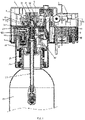
- FIG. 1
- is a cross-sectional view of the prior art.
- FIG. 2
- is a view A-A of
FIG. 1 . - FIG. 3
- is a view B-B of
FIG. 1 . - FIG. 4
- is a perspective view of the present patent.
- FIG. 5
- is a cross-sectional view of the present patent.
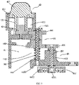
- FIG. 6
- is a view C-C of
FIG. 5 . - FIG. 7
- is a view D-D of
FIG. 6 . - FIG. 8
- is a top view of a driving mechanism according to the present patent.
- FIG. 9
- is a view E-E of
FIG. 8 . - The present patent will be further described with reference to the attached drawings.
- As shown in
FIG. 1 , a pressure-adjustable pneumatic system of a soda machine comprises anupper cover 1, anair inlet support 2, anair distribution valve 3, asub-machine support 5, a safety valve 8, and a piston-typepressure driving device 9. Theair distribution valve 3 comprises anair inlet cavity 31, anair inlet interface 311 communicated with the air inlet cavity, anexhaust cavity 32 surrounding the air inlet cavity, anexhaust driving pipeline 33 communicated with the exhaust cavity, and anexhaust valve 34 provided on the exhaust driving pipeline. Theexhaust driving pipeline 33 is provided with aninterface 331. The piston-typepressure driving device 9 comprises acylinder 91 with an open end, anair inlet interface 911 provided at the air inlet end of the cylinder, apiston 92, asealing rubber plug 921, anejector rod 93 connected with the piston, a spring and apush rod nut 94. The open end of thecylinder 91 is provided with internal threads. Thepush rod nut 94 comprises abody part 941, anoperating part 942 surrounding the body part, anupper guide hole 943 provided on the body part and acounter hole 944. Thebody part 941 comprises an external thread part and a sealing part. The sealingrubber plug 921 is provided at one end of thepiston 92. The sealingrubber plug 921 is fitted with the closed air inlet of thecylinder 91. The spring is sleeved on theejector rod 93. The external thread of thepush rod nut 94 is screwed with the internal thread of thecylinder 91. The spring extends into thecounter bore 944. Theejector rod 93 extends through theguide hole 943. The piston-typepressure driving device 9 is fixed on the lower surface of theair inlet support 2. Theair inlet interface 911 is inserted into theinterface 331. Thesub-machine support 5 is connected with theouter cover 1 and the lower end of theair inlet support 2. - The
upper cover 1 is provided with aknob hole 1A. The operatingpart 942 is provided with ashaft head 9421; theair inlet support 2 is provided with acircular counter bore 2A, the bottom plate of thecircular counter bore 2A is provided with a through hole, and the through hole is opposite to theshaft head 9421. - The system further comprises a driving
base 41, aknob 42, adriving gear 43, adriving wheel set 44, a driven wheel set 45, and adrive gear 46. - The driving
base 41 comprises acircular base cavity 411, a drivingwheel set base 412 and a drivenwheel set base 413, wherein thecircular base cavity 411 is communicated with the drivingwheel set base 412. - The driving wheel set 44 comprises a
first gear 441, asecond gear 442 and a fixedshaft 443. The driven wheel set 45 comprises aspeed reducing wheel 451, a drivenwheel 452 and arotating shaft 453. The drivenwheel 452 comprises ashaft body 4521, acylinder 4522 with an open lower part and teeth provided at the open end of the cylinder. - The driving
base 41 is fixed on theair inlet support 2. The lower shaft body of thedriving gear 43 is rotatably fitted with the bottom plate of thecircular base cavity 411. The connecting rod at the upper end is connected with the connectingpart 421 of theknob 42. Thebody part 422 of theknob 42 is rotatably fitted with thecircular base cavity 411. Thefirst gear 441 and thesecond gear 442 are provided vertically and pivotedly connected to a drivingwheel set base 412 by means of a fixedshaft 443. Thefirst gear 441 is engaged with thedriving gear 43. Arotating shaft 453 is rotatably fitted with a drivenwheel set base 413. The upper end of the rotating shaft is fixedly connected to aspeed reducing wheel 451, and the lower end of the rotating shaft is connected to ashaft body 4521 of a drivengear 452. - The
drive gear 46 is fixedly connected to ashaft head 9421. Thedrive gear 46 extends into a circular counter bore 2A through a through hole. The drivengear 452 is located in thecircular counter bore 2A and engaged with thedrive gear 46. Ahandheld part 421 of theknob 42 extends out of theupper cover 1 through aknob hole 1A. - The lower end of the shaft base of the
first gear 441 of the driving wheel set 44 is provided with a sub-clutch sleeve 4411, the upper end of the shaft base of thesecond gear 442 is provided with a female clutch sleeve 4421, and the upper end of the fixedshaft 443 is provided with an external thread. - The upper base plate of the driving
wheel set base 412 is provided with a threadedhole 4121, and the lower base plate is provided with a fixedhole 4122. - The system further comprises a
tension spring 444. - The upper end of the fixed
shaft 443 is screwed with the threadedhole 4121 and the lower end thereof is inserted with the fixedhole 4122. Thetension spring 444 is sleeved on the fixedshaft 443. The upper end and the lower end of thetension spring 444 are fitted with the shaft base and the lower base plate of thesecond gear 442, respectively. The sub-clutch sleeve 4411 and the female clutch sleeve 4421 are engaged. - The driving
base 41 is provided with agear cavity 414, and thegear cavity 414 is communicated with thecylindrical base 411 through a guide hole. - The system further comprises a sliding
rod 61 and apressure spring 62, wherein the slidingrod 61 is provided with aspring base plate 611. - The
driven end 612 of the slidingrod 61 passes through apressure spring 62. One end of thepressure spring 62 is opposite to the end plate of thegear cavity 414 and the other end thereof is fitted with thespring base plate 611. The driving end of the slidingrod 61 is fitted with the gear hole on the connectingpart 421 of theknob 42 through the guide hole. - The above is only the preferred embodiment of the present patent. It should be pointed out that several improvements and modifications can be made without departing from the principle of the present patent for those skilled in the art, which is also regarded as the scope of protection of the present patent.
Claims (3)
- A pressure-adjustable pneumatic system of a soda machine, comprising an upper cover, an air inlet support, an air distribution valve, a sub-machine support, a safety valve, and a piston-type pressure driving device, wherein the air distribution valve comprises an air inlet cavity, an air inlet interface communicated with the air inlet cavity, an exhaust cavity surrounding the air inlet cavity, an exhaust driving pipeline communicated with the exhaust cavity, and an exhaust valve provided on the exhaust driving pipeline, the exhaust driving pipeline is provided with an interface, the piston-type pressure driving device comprises a cylinder with an open end, an air inlet interface provided at the air inlet end of the cylinder, a piston, a sealing rubber plug, an ejector rod connected with the piston, a spring and a push rod nut, wherein the open end of the cylinder is provided with internal threads; the push rod nut comprises a body part, an operating part surrounding the body part, an upper guide hole provided on the body part and a counter hole; the body part comprises an external thread part and a sealing part; the sealing rubber plug is provided at one end of the piston, the sealing rubber plug is fitted with the closed air inlet of the cylinder, the spring is sleeved on the ejector rod, the external thread of the push rod nut is screwed with the internal thread of the cylinder; the spring extends into the counter bore, the ejector rod extends through the guide hole, the piston-type pressure driving device is fixed on the air inlet support, the air inlet interface is inserted into the interface; the sub-machine support is connected with the outer cover and the lower end of the air inlet support; wherein the upper cover is provided with a knob hole; the operating part is provided with a shaft head; the air inlet support is provided with a circular counter bore, the bottom plate of the circular counter bore is provided with a through hole, and the through hole is opposite to the shaft head;the system further comprises a driving base, a knob, a driving gear, a driving wheel set, a driven wheel set, and a drive gear;the driving base comprises a circular base cavity, a driving wheel set base and a driven wheel set base, wherein the circular base cavity is communicated with the driving wheel set base; the driving wheel set comprises a first gear, a second gear and a fixed shaft; the driven wheel set comprises a speed reducing wheel, a driven wheel and a rotating shaft, the driven wheel comprises a shaft body, a cylinder with an open lower part and teeth provided at the open end of the cylinder;the driving base is fixed on the air inlet support, the lower shaft body of the driving gear is rotatably fitted with the bottom plate of the circular base cavity, the connecting rod at the upper end is connected with the connecting part of the knob; the first gear and the second gear are provided vertically and pivotedly connected to a driving wheel set base by means of a fixed shaft, the first gear is engaged with the driving gear; a rotating shaft is rotatably fitted with a driven wheel set base, the upper end of the rotating shaft is fixedly connected to a speed reducing wheel, and the lower end of the rotating shaft is connected to a shaft body of a driven gear;the drive gear is fixedly connected to a shaft head, the drive gear extends into a circular counter bore through a through hole, and the driven gear is located in the circular counter bore and engaged with the drive gear; and a handheld part of the knob extends out of the upper cover through a knob hole.
- The pressure-adjustable pneumatic system of a soda machine according to claim 1, wherein the lower end of the shaft base of the first gear of the driving wheel set is provided with a sub-clutch sleeve, the upper end of the shaft base of the second gear is provided with a female clutch sleeve, and the upper end of the fixed shaft is provided with an external thread;the upper base plate of the driving wheel set base is provided with a threaded hole, and the lower base plate is provided with a fixed hole;the system further comprises a tension spring,the upper end of the fixed shaft is screwed with the threaded hole and the lower end thereof is inserted with the fixed hole; the tension spring is sleeved on the fixed shaft; the upper end and the lower end of the tension spring are fitted with the shaft base and the lower base plate of the second gear, respectively; and the sub-clutch sleeve and the female clutch sleeve are engaged.
- The pressure-adjustable pneumatic system of a soda machine according to claim 1, wherein the driving base is provided with a gear cavity, and the gear cavity is communicated with the cylindrical base through a guide hole;the system further comprises a sliding rod and a pressure spring, wherein the sliding rod is provided with a spring base plate;the driven end of the sliding rod passes through a pressure spring, one end of the pressure spring is fitted with the end plate of the gear cavity and the other end thereof is fitted with the spring base plate, and the driving end of the sliding rod is fitted with the gear hole on the connecting part of the knob through the guide hole.
Applications Claiming Priority (2)
| Application Number | Priority Date | Filing Date | Title |
|---|---|---|---|
| CN201920694207.1U CN210520791U (en) | 2019-05-14 | 2019-05-14 | Pneumatic system of aerated water machine with adjustable pressure |
| PCT/CN2020/089795 WO2020228699A1 (en) | 2019-05-14 | 2020-05-12 | Pressure-adjustable pneumatic system of soda machine |
Publications (4)
| Publication Number | Publication Date |
|---|---|
| EP3984420A1 true EP3984420A1 (en) | 2022-04-20 |
| EP3984420A4 EP3984420A4 (en) | 2023-10-11 |
| EP3984420B1 EP3984420B1 (en) | 2025-02-12 |
| EP3984420C0 EP3984420C0 (en) | 2025-02-12 |
Family
ID=70593385
Family Applications (1)
| Application Number | Title | Priority Date | Filing Date |
|---|---|---|---|
| EP20804926.2A Active EP3984420B1 (en) | 2019-05-14 | 2020-05-12 | Pressure-adjustable pneumatic system of soda machine |
Country Status (6)
| Country | Link |
|---|---|
| US (1) | US20220218142A1 (en) |
| EP (1) | EP3984420B1 (en) |
| JP (1) | JP7447369B2 (en) |
| KR (1) | KR20210002766U (en) |
| CN (1) | CN210520791U (en) |
| WO (1) | WO2020228699A1 (en) |
Families Citing this family (7)
| Publication number | Priority date | Publication date | Assignee | Title |
|---|---|---|---|---|
| EP4133948A1 (en) * | 2021-08-13 | 2023-02-15 | Guan, Jin Ye | Sub-machine of soda fountain with adjustable exhaust velocity |
| CN218355731U (en) * | 2022-08-16 | 2023-01-24 | 江门市伊科迈特电子科技有限公司 | Bubble water machine with automatic air inlet resetting function |
| CN117982006A (en) * | 2022-10-31 | 2024-05-07 | 江门市伊科迈特电子科技有限公司 | A sparkling water main machine using a transition gas tank and a sparkling water machine using the same |
| US12611638B2 (en) | 2023-10-24 | 2026-04-28 | Sharkninja Operating Llc | Ratchet system for a gas canister in a beverage system |
| US12636623B2 (en) | 2023-12-11 | 2026-05-26 | Sodastream Industries Ltd. | Carbonation machine with fixed carbonation pulse duration |
| USD1132072S1 (en) | 2024-05-31 | 2026-06-30 | Sharkninja Operating Llc | Beverage dispenser |
| CN222997735U (en) * | 2024-08-12 | 2025-06-20 | 玛西(北京)国际品牌管理有限公司 | Coffee machine pressure regulating device and coffee machine extraction system |
Family Cites Families (14)
| Publication number | Priority date | Publication date | Assignee | Title |
|---|---|---|---|---|
| GB2093714A (en) * | 1981-02-24 | 1982-09-08 | Thorn Cascade Co Ltd | Carbonated drinks machine |
| EP0935992A1 (en) * | 1998-02-10 | 1999-08-18 | Kautz, Peter | Apparatus for enriching a liquid with gas |
| US7784396B2 (en) * | 2006-08-21 | 2010-08-31 | Electrical And Electronics Limited | Hydraulic sealing assembly for a beverage machine brewing head |
| CN201995544U (en) * | 2011-03-15 | 2011-10-05 | 宋宁 | Aerated water machine with safety device |
| CN201995545U (en) * | 2011-03-15 | 2011-10-05 | 宋宁 | Aerated water machine with pressure regulator |
| CN202020297U (en) * | 2011-03-16 | 2011-11-02 | 连鸿权 | Machine for making carbon dioxide carbonic acid soft drink |
| CN202262390U (en) * | 2011-10-18 | 2012-06-06 | 宋宁 | Portable aerated water machine with small replaceable steel cylinder |
| CN105078252B (en) * | 2015-09-14 | 2017-10-10 | 深圳市宝威家用电器有限公司 | A kind of Household soda water machine |
| CN205514109U (en) * | 2016-01-29 | 2016-08-31 | 宋宁 | A kind of soda machine that automatically closes the air outlet valve |
| CA2958165A1 (en) * | 2017-02-16 | 2018-08-16 | Ibev Holdings Inc. | Carbonation device with an automatic pressurizing system |
| CN206904569U (en) * | 2017-03-31 | 2018-01-19 | 宋飞 | A kind of aerated water machine steel cylinder device |
| CN208692985U (en) * | 2018-04-27 | 2019-04-05 | 宁波威尔升电器有限公司 | A kind of aerated water machine of automatic exhausting |
| CN209863393U (en) * | 2019-02-25 | 2019-12-31 | 关进业 | Sub-machine of aerated water machine with adjustable exhaust |
| CN210810568U (en) * | 2019-04-19 | 2020-06-23 | 关进业 | Pneumatic system of aerated water machine integrating air intake, driving and pressure relief exhaust |
-
2019
- 2019-05-14 CN CN201920694207.1U patent/CN210520791U/en active Active
-
2020
- 2020-05-12 JP JP2021567885A patent/JP7447369B2/en active Active
- 2020-05-12 KR KR2020217000067U patent/KR20210002766U/en not_active Ceased
- 2020-05-12 EP EP20804926.2A patent/EP3984420B1/en active Active
- 2020-05-12 US US17/595,206 patent/US20220218142A1/en active Pending
- 2020-05-12 WO PCT/CN2020/089795 patent/WO2020228699A1/en not_active Ceased
Also Published As
| Publication number | Publication date |
|---|---|
| CN210520791U (en) | 2020-05-15 |
| EP3984420A4 (en) | 2023-10-11 |
| EP3984420B1 (en) | 2025-02-12 |
| WO2020228699A1 (en) | 2020-11-19 |
| US20220218142A1 (en) | 2022-07-14 |
| EP3984420C0 (en) | 2025-02-12 |
| KR20210002766U (en) | 2021-12-10 |
| JP2023502808A (en) | 2023-01-26 |
| JP7447369B2 (en) | 2024-03-12 |
Similar Documents
| Publication | Publication Date | Title |
|---|---|---|
| EP3984420B1 (en) | Pressure-adjustable pneumatic system of soda machine | |
| CN202140369U (en) | Single-acting cylinder | |
| SE458426B (en) | INFO DEVICE FOR THREADING | |
| CN208764356U (en) | A kind of hand liquid-operated flat valve | |
| CN210810568U (en) | Pneumatic system of aerated water machine integrating air intake, driving and pressure relief exhaust | |
| CN206046359U (en) | Piezoelectric type injection valve | |
| CN117740456A (en) | Petroleum sampler | |
| CN111728483A (en) | A combined portable coffee machine | |
| CN205032335U (en) | Dispensing device | |
| CN109990990A (en) | A kind of nitrogen gas spring is multi-functional to fill inspection tool | |
| US20220221075A1 (en) | Pressure-regulating-type sub-machine of soda machine | |
| US6662828B1 (en) | Telescoping filling head | |
| CN208376247U (en) | A kind of labelling apparatus of ampoule bottle | |
| CN216296918U (en) | Adjustable dispensing valve | |
| CN111120662A (en) | Pneumatic buffering angle seat valve | |
| CN200999893Y (en) | Pressure holding valve | |
| US20200031647A1 (en) | One kind of red wine bottle opener | |
| CN208845847U (en) | A kind of pneumatic actuator of single-acting | |
| TWM598108U (en) | Pneumatic system of pressure-adjustable soda machine | |
| CN223690655U (en) | An airtightness test sealing device | |
| CN221074193U (en) | Oil field well head control valve | |
| CN111396602A (en) | Explosion-proof inflation valve | |
| CN203798046U (en) | Leak-proof thimble device | |
| CN222686991U (en) | A valve body structure for a hydraulic cylinder | |
| CN219409212U (en) | Servo three-jaw capping head device |
Legal Events
| Date | Code | Title | Description |
|---|---|---|---|
| STAA | Information on the status of an ep patent application or granted ep patent |
Free format text: STATUS: THE INTERNATIONAL PUBLICATION HAS BEEN MADE |
|
| PUAI | Public reference made under article 153(3) epc to a published international application that has entered the european phase |
Free format text: ORIGINAL CODE: 0009012 |
|
| STAA | Information on the status of an ep patent application or granted ep patent |
Free format text: STATUS: REQUEST FOR EXAMINATION WAS MADE |
|
| 17P | Request for examination filed |
Effective date: 20211116 |
|
| AK | Designated contracting states |
Kind code of ref document: A1 Designated state(s): AL AT BE BG CH CY CZ DE DK EE ES FI FR GB GR HR HU IE IS IT LI LT LU LV MC MK MT NL NO PL PT RO RS SE SI SK SM TR |
|
| DAV | Request for validation of the european patent (deleted) | ||
| DAX | Request for extension of the european patent (deleted) | ||
| REG | Reference to a national code |
Ref country code: DE Ref legal event code: R079 Free format text: PREVIOUS MAIN CLASS: A47J0031400000 Ipc: B01F0023236000 Ref country code: DE Ref legal event code: R079 Ref document number: 602020046002 Country of ref document: DE Free format text: PREVIOUS MAIN CLASS: A47J0031400000 Ipc: B01F0023236000 |
|
| A4 | Supplementary search report drawn up and despatched |
Effective date: 20230912 |
|
| RIC1 | Information provided on ipc code assigned before grant |
Ipc: F16K 17/06 20060101ALI20230906BHEP Ipc: A23L 2/54 20060101ALI20230906BHEP Ipc: B01F 23/2361 20220101ALI20230906BHEP Ipc: B01F 23/236 20220101AFI20230906BHEP |
|
| GRAP | Despatch of communication of intention to grant a patent |
Free format text: ORIGINAL CODE: EPIDOSNIGR1 |
|
| STAA | Information on the status of an ep patent application or granted ep patent |
Free format text: STATUS: GRANT OF PATENT IS INTENDED |
|
| RIC1 | Information provided on ipc code assigned before grant |
Ipc: F16K 17/06 20060101ALI20240813BHEP Ipc: A23L 2/54 20060101ALI20240813BHEP Ipc: B01F 23/2361 20220101ALI20240813BHEP Ipc: B01F 23/236 20220101AFI20240813BHEP |
|
| INTG | Intention to grant announced |
Effective date: 20240904 |
|
| GRAS | Grant fee paid |
Free format text: ORIGINAL CODE: EPIDOSNIGR3 |
|
| GRAJ | Information related to disapproval of communication of intention to grant by the applicant or resumption of examination proceedings by the epo deleted |
Free format text: ORIGINAL CODE: EPIDOSDIGR1 |
|
| GRAL | Information related to payment of fee for publishing/printing deleted |
Free format text: ORIGINAL CODE: EPIDOSDIGR3 |
|
| STAA | Information on the status of an ep patent application or granted ep patent |
Free format text: STATUS: REQUEST FOR EXAMINATION WAS MADE |
|
| RAP1 | Party data changed (applicant data changed or rights of an application transferred) |
Owner name: GUANGZHOU YIKE TRADING CO., LTD. |
|
| RIN1 | Information on inventor provided before grant (corrected) |
Inventor name: GUAN, JINYE |
|
| GRAP | Despatch of communication of intention to grant a patent |
Free format text: ORIGINAL CODE: EPIDOSNIGR1 |
|
| STAA | Information on the status of an ep patent application or granted ep patent |
Free format text: STATUS: GRANT OF PATENT IS INTENDED |
|
| GRAA | (expected) grant |
Free format text: ORIGINAL CODE: 0009210 |
|
| STAA | Information on the status of an ep patent application or granted ep patent |
Free format text: STATUS: THE PATENT HAS BEEN GRANTED |
|
| INTC | Intention to grant announced (deleted) | ||
| INTG | Intention to grant announced |
Effective date: 20250102 |
|
| AK | Designated contracting states |
Kind code of ref document: B1 Designated state(s): AL AT BE BG CH CY CZ DE DK EE ES FI FR GB GR HR HU IE IS IT LI LT LU LV MC MK MT NL NO PL PT RO RS SE SI SK SM TR |
|
| REG | Reference to a national code |
Ref country code: GB Ref legal event code: FG4D |
|
| REG | Reference to a national code |
Ref country code: CH Ref legal event code: EP |
|
| REG | Reference to a national code |
Ref country code: DE Ref legal event code: R096 Ref document number: 602020046002 Country of ref document: DE |
|
| REG | Reference to a national code |
Ref country code: IE Ref legal event code: FG4D |
|
| U01 | Request for unitary effect filed |
Effective date: 20250310 |
|
| U07 | Unitary effect registered |
Designated state(s): AT BE BG DE DK EE FI FR IT LT LU LV MT NL PT RO SE SI Effective date: 20250318 |
|
| U20 | Renewal fee for the european patent with unitary effect paid |
Year of fee payment: 6 Effective date: 20250514 |
|
| PG25 | Lapsed in a contracting state [announced via postgrant information from national office to epo] |
Ref country code: RS Free format text: LAPSE BECAUSE OF FAILURE TO SUBMIT A TRANSLATION OF THE DESCRIPTION OR TO PAY THE FEE WITHIN THE PRESCRIBED TIME-LIMIT Effective date: 20250512 |
|
| PG25 | Lapsed in a contracting state [announced via postgrant information from national office to epo] |
Ref country code: PL Free format text: LAPSE BECAUSE OF FAILURE TO SUBMIT A TRANSLATION OF THE DESCRIPTION OR TO PAY THE FEE WITHIN THE PRESCRIBED TIME-LIMIT Effective date: 20250212 |
|
| PG25 | Lapsed in a contracting state [announced via postgrant information from national office to epo] |
Ref country code: ES Free format text: LAPSE BECAUSE OF FAILURE TO SUBMIT A TRANSLATION OF THE DESCRIPTION OR TO PAY THE FEE WITHIN THE PRESCRIBED TIME-LIMIT Effective date: 20250212 |
|
| PG25 | Lapsed in a contracting state [announced via postgrant information from national office to epo] |
Ref country code: IS Free format text: LAPSE BECAUSE OF FAILURE TO SUBMIT A TRANSLATION OF THE DESCRIPTION OR TO PAY THE FEE WITHIN THE PRESCRIBED TIME-LIMIT Effective date: 20250612 Ref country code: NO Free format text: LAPSE BECAUSE OF FAILURE TO SUBMIT A TRANSLATION OF THE DESCRIPTION OR TO PAY THE FEE WITHIN THE PRESCRIBED TIME-LIMIT Effective date: 20250512 |
|
| PG25 | Lapsed in a contracting state [announced via postgrant information from national office to epo] |
Ref country code: HR Free format text: LAPSE BECAUSE OF FAILURE TO SUBMIT A TRANSLATION OF THE DESCRIPTION OR TO PAY THE FEE WITHIN THE PRESCRIBED TIME-LIMIT Effective date: 20250212 |
|
| PG25 | Lapsed in a contracting state [announced via postgrant information from national office to epo] |
Ref country code: GR Free format text: LAPSE BECAUSE OF FAILURE TO SUBMIT A TRANSLATION OF THE DESCRIPTION OR TO PAY THE FEE WITHIN THE PRESCRIBED TIME-LIMIT Effective date: 20250513 |
|
| PG25 | Lapsed in a contracting state [announced via postgrant information from national office to epo] |
Ref country code: SM Free format text: LAPSE BECAUSE OF FAILURE TO SUBMIT A TRANSLATION OF THE DESCRIPTION OR TO PAY THE FEE WITHIN THE PRESCRIBED TIME-LIMIT Effective date: 20250212 |
|
| PG25 | Lapsed in a contracting state [announced via postgrant information from national office to epo] |
Ref country code: CZ Free format text: LAPSE BECAUSE OF FAILURE TO SUBMIT A TRANSLATION OF THE DESCRIPTION OR TO PAY THE FEE WITHIN THE PRESCRIBED TIME-LIMIT Effective date: 20250212 |
|
| PG25 | Lapsed in a contracting state [announced via postgrant information from national office to epo] |
Ref country code: SK Free format text: LAPSE BECAUSE OF FAILURE TO SUBMIT A TRANSLATION OF THE DESCRIPTION OR TO PAY THE FEE WITHIN THE PRESCRIBED TIME-LIMIT Effective date: 20250212 |
|
| PLBE | No opposition filed within time limit |
Free format text: ORIGINAL CODE: 0009261 |
|
| STAA | Information on the status of an ep patent application or granted ep patent |
Free format text: STATUS: NO OPPOSITION FILED WITHIN TIME LIMIT |
|
| REG | Reference to a national code |
Ref country code: CH Ref legal event code: H13 Free format text: ST27 STATUS EVENT CODE: U-0-0-H10-H13 (AS PROVIDED BY THE NATIONAL OFFICE) Effective date: 20251223 |
|
| REG | Reference to a national code |
Ref country code: CH Ref legal event code: L10 Free format text: ST27 STATUS EVENT CODE: U-0-0-L10-L00 (AS PROVIDED BY THE NATIONAL OFFICE) Effective date: 20251224 |
|
| PG25 | Lapsed in a contracting state [announced via postgrant information from national office to epo] |
Ref country code: CH Free format text: LAPSE BECAUSE OF NON-PAYMENT OF DUE FEES Effective date: 20250531 |
|
| 26N | No opposition filed |
Effective date: 20251113 |
|
| GBPC | Gb: european patent ceased through non-payment of renewal fee |
Effective date: 20250512 |
|
| PG25 | Lapsed in a contracting state [announced via postgrant information from national office to epo] |
Ref country code: MC Free format text: LAPSE BECAUSE OF FAILURE TO SUBMIT A TRANSLATION OF THE DESCRIPTION OR TO PAY THE FEE WITHIN THE PRESCRIBED TIME-LIMIT Effective date: 20250212 |
|
| PG25 | Lapsed in a contracting state [announced via postgrant information from national office to epo] |
Ref country code: GB Free format text: LAPSE BECAUSE OF NON-PAYMENT OF DUE FEES Effective date: 20250512 |
|
| PG25 | Lapsed in a contracting state [announced via postgrant information from national office to epo] |
Ref country code: IE Free format text: LAPSE BECAUSE OF NON-PAYMENT OF DUE FEES Effective date: 20250512 |
|
| U20 | Renewal fee for the european patent with unitary effect paid |
Year of fee payment: 7 Effective date: 20260417 |
|
| PG25 | Lapsed in a contracting state [announced via postgrant information from national office to epo] |
Ref country code: CY Free format text: LAPSE BECAUSE OF FAILURE TO SUBMIT A TRANSLATION OF THE DESCRIPTION OR TO PAY THE FEE WITHIN THE PRESCRIBED TIME-LIMIT Effective date: 20250212 |