EP3984343A2 - Cutter implement with curtain - Google Patents
Cutter implement with curtain Download PDFInfo
- Publication number
- EP3984343A2 EP3984343A2 EP21200670.4A EP21200670A EP3984343A2 EP 3984343 A2 EP3984343 A2 EP 3984343A2 EP 21200670 A EP21200670 A EP 21200670A EP 3984343 A2 EP3984343 A2 EP 3984343A2
- Authority
- EP
- European Patent Office
- Prior art keywords
- curtain
- cutter
- layer
- stiffness
- strips
- Prior art date
- Legal status (The legal status is an assumption and is not a legal conclusion. Google has not performed a legal analysis and makes no representation as to the accuracy of the status listed.)
- Granted
Links
Images






Classifications
-
- A—HUMAN NECESSITIES
- A01—AGRICULTURE; FORESTRY; ANIMAL HUSBANDRY; HUNTING; TRAPPING; FISHING
- A01D—HARVESTING; MOWING
- A01D57/00—Delivering mechanisms for harvesters or mowers
- A01D57/01—Devices for leading crops to the mowing apparatus
-
- A—HUMAN NECESSITIES
- A01—AGRICULTURE; FORESTRY; ANIMAL HUSBANDRY; HUNTING; TRAPPING; FISHING
- A01D—HARVESTING; MOWING
- A01D43/00—Mowers combined with apparatus performing additional operations while mowing
- A01D43/10—Mowers combined with apparatus performing additional operations while mowing with means for crushing or bruising the mown crop
-
- A—HUMAN NECESSITIES
- A01—AGRICULTURE; FORESTRY; ANIMAL HUSBANDRY; HUNTING; TRAPPING; FISHING
- A01D—HARVESTING; MOWING
- A01D57/00—Delivering mechanisms for harvesters or mowers
- A01D57/22—Delivering mechanisms for harvesters or mowers for standing stalks
Definitions
- the present disclosure relates generally to a cutter implement for cutting crop material.
- Forages such as grasses, legumes, maize, and other crop residues, are commonly cut by a cutter implement, such as but not limited to, a mower or mower-conditioner.
- a cutter implement such as but not limited to, a mower or mower-conditioner.
- the types of crops harvested vary widely from short crops that are compliant and flexible to tall crops that are relatively ridged and inflexible. As a general rule however, taller crops are typically more stiff/rigid than short crops so as to stand steadily on the ground.
- a cutter implement for cutting crop material may include a housing, a cutter, and a curtain.
- the housing has a forward end for engaging the crop material when moving in a direction of operation.
- the housing at least partially defines a cutting region disposed at the forward end.
- the cutter is coupled to the housing and can cut the crop material in the cutting region.
- the curtain is coupled to the forward end of the housing and is positioned forward of the cutter relative to the direction of operation for engaging and leaning the crop material upstream of the cutter.
- the curtain includes a stiffness control feature operable to control a vertical stiffness of the curtain to provide a variable vertical stiffness that increases with an increase in a bend angle of the curtain rearward relative to the direction of operation.
- a curtain apparatus for a cutter implement includes a curtain operable to be coupled to the cutter implement.
- the curtain includes a stiffness control feature operable to control a vertical stiffness of the curtain to provide a variable vertical stiffness that increases with an increase in a bend angle of the curtain rearward relative to a direction of operation.
- a cutter implement 10 include a cutter 30 extending in a forward direction relative to the direction of the operation V, which is the travel direction.
- a housing 20 of the cutter implement 10 is omitted in FIG. 1 but is shown in FIGS. 2A and 2B .
- a cutting region 28 is defined in front of the cutter 30.
- a crop processor 80 is positioned rearward of the cutter relative to the direction of operation (travel) and operable to condition cut crop material 90.
- the crop processor 80 in one implementation includes a first conditioning roll 82 and a second conditioning roll 84 engaging with each other to condition the crop material 90.
- the crop processor 80 may be implemented in another configuration not shown or described herein that is capable of processing cut crop as understood by those skilled in the art.
- the cutter implement 10 may include, but is not limited to, a mower and a mower-conditioner.
- the mower and/or mower conditioner may be drawn by a vehicle, such as but not limited to a tractor or other similar vehicle, or may be a self-propelled implement having motive power, steering systems, control systems, etc.
- Leaning the crop 90 forward may provide several benefits for crop cutting and crop conditioning process. For example, it may allow the base end of the stems to be fed into the first conditioning roll 82 and the second conditioning roll 84 as shown in FIG. 1 . Feeding the crop (material) 90 into the crop processor 80 in this manner has shown to improve cutting performance by minimizing re-cutting at the cutter 30 and it improves cut height uniformity. However, the degree to which the crops 90 are flexed forward greatly affects how much the performance can be improved. In fact, if the crop 90 is over-flexed it may hinder cutting performance.
- the crop 90 may be flexed forward "slightly" so that the stem remains intact and erect but not “over-bent” such that the stem is kinked/yielded, causing the crop to permanently tip or lay on the ground prior to being severed.
- taller crops are typically more stiff/rigid than short crops. Therefore, a bending force required to bend rigid taller crops forward may need to be stronger than the bending force required to bend shorter more compliant crops forward.
- the present disclosure includes a cutter implement and a cutter apparatus, which have a stiffness control feature for a curtain operable to control a vertical stiffness of the curtain to determine the force applied to the crop.
- the cutter implement 10 may include a housing 20, the cutter 30, and a curtain 50.
- the housing 20 includes an upper frame portion 22, a first lateral frame portion 24, and a second lateral frame portion 26.
- the first lateral frame portion 24 and the second lateral frame portion 26 are spaced apart from each other and disposed on opposing lateral sides of the housing 20 relative to a central longitudinal axis 25 of the housing 20.
- the housing 20 also has a forward end 222, included by the upper frame portion 22 in one implementation, for engaging the crop material 90 when moving in a direction of operation V.
- the housing 20 at least partially defines the cutting region 28 disposed at or near the forward end 222.
- the cutter 30, as shown in FIGS. 2A and 2B is coupled to the housing 20 and is operable to cut the crop material 90 in the cutting region 28.
- the cutter 30 is configured as a cutter-bar extending laterally transverse relative to the central longitudinal axis 25 of the housing 20, across a width of the cutter implement 10.
- the curtain 50 is coupled to the forward end 222 of the housing 20 and is positioned forward of the cutter 30 relative to the direction of operation V for engaging and leaning the crop material 90 upstream of the cutter 30, as shown in FIG. 2A and 2B .
- the curtain 50 at least partially defines the cutting region 28.
- the curtain 50 has one section coupled laterally to the forward end 222, as shown in FIG. 2A .
- the curtain 50 may include multiple sections coupled laterally to the forward end 222.
- the curtain 50 may include three sections 501, 502, 503.
- the middle section 502 has an offset to the other two adjacent sections 501 and 503 in the direction of operation V.
- the number of the section(s) is only for explanatory purpose, and it can be varied depending on the particular need.
- the number of the sections being equal to or more than two may allow the operator to replace part of the curtain 50 section by section.
- the implementations of the curtain 50 described in this disclosure may be applied to single section or more than one section of the curtain 50.
- the curtain 50 is moveable in a rearward direction relative to the direction of operation V.
- the curtain 50 contacts the crop 90 and may be moved in the rearward direction due to the stiffness of the crop 90.
- the crop 90 may be simultaneously flexed forward due to the force applied from the curtain 50.
- the weight, material, shape, and/or other characteristic of the curtain 50 affect the vertical stiffness of the curtain, and may bias the curtain 50 toward its original position, which provides a resistance of the curtain 50 against rearward movement after the curtain 50 contacts the crop 90.
- the curtain 50 includes a stiffness control feature 60 operable to control the vertical stiffness of the curtain 50.
- the stiffness control feature 60 is operable to provide a variable vertical stiffness that increases with an increase in a bend angle ⁇ of the curtain 50 rearward relative to the direction of operation V.
- the vertical stiffness of the curtain 50 is directly related to the resistance against bending resulting from the pushing of the crop material 90 acting on the curtain 50.
- FIGS. 3B-3D illustrate the bend angle ⁇ , can be defined at any point at the (section of) curtain 50 relative to vertical line(s).
- the location and the shape of the stiffness control feature 60 shown in FIGS. 3A-3D are merely a demonstration.
- the stiffness control feature 60 can be disposed inside or outside the curtain 50 or as characteristic(s) of the curtain 50 itself, the details of which will be described later.
- the vertical line L (L1) overlaps with the reference line L Ref of the curtain 50, before the curtain 50 contacts the crop material 90.
- the reference line L Ref may be drawn in the middle part of the curtain for showing the extent (e.g. the bend angle ⁇ ) the curtain 50 bends.
- the curtain 50 is hung vertically relative to a ground surface before the curtain 50 engages the crop material 90 and exhibits the bend angle ⁇ substantially equal to zero.
- one bend angle ⁇ between a vertical line L3 and the reference line L Ref increases from zero to the bend angle ⁇ 3
- another bend angle ⁇ between a vertical line L4 and the reference line L Ref increases from zero to the bend angle ⁇ 4.
- the intersection P3 of the vertical line L3 and the reference line L Ref is at the top of the upper portion 512.
- the intersection P4 of the vertical line L4 and the reference line L Ref is at the bottom of the upper portion 512 or the top of the lower portion 514 of the curtain 50.
- the number of the vertical lines and intersections can be more than two, up to infinite, such as, for example, when the curtain 50 at least partially includes a curved shape.
- stiffness control feature 60 shown in FIGS. 3A-3D is not limited to what it is shown.
- the stiffness control feature 60 may have, alone or in combination, variable thickness, variable durometer, multiple portions coupled to one another with different thickness, multiple layers, multiple layers with multiple strips, and weigh element(s).
- FIG. 4 illustrates the first implementation of a stiffness control feature 60, 61.
- the stiffness control feature 61 includes a thickness of the curtain 50, and the thickness of the curtain 50 is variable in a vertical direction.
- the thickness of the curtain 50 increases from a bottom of the curtain 50 to a top of the curtain 50, proportionally in this implementation, so as to form a slope on a forward surface 612 operable to engage the crop material 90.
- the rearward surface 614, the opposite surface of the forward surface 612 may be vertical to the ground surface.
- the stiffness control feature 62 of the curtain 50 has variable durometer, the higher portion of the curtain 50, the greater of durometer. For example, an upper portion 622 of the curtain 50 has greater durometer than does a lower portion 624 of the curtain 50. Therefore, the stiffness control feature 62 is operable to increase the vertical stiffness of the curtain 50 from a bottom of the curtain 50 to a top of the curtain 50.
- the stiffness control feature 63 of curtain 50 includes a first portion 632, a second portion 634 coupled to a lower part of the first portion 632, and a third portion 636 coupled to a lower part of the second portion 634.
- the curtain 50 may be made by one-piece (not shown), with a thickness of the first portion 632 is greater than a thickness of the second portion 634, and the thickness of the second portion 634 is greater than a thickness of the third portion 636.
- the stiffness control feature 63 may include multiple layers with different height stacking together to form the first portion 632, second portion 634, and the third portion 636.
- FIG. 7 illustrates the fourth implementation of a stiffness control feature 60, 64 of the curtain 50 having multiple layers.
- the number of the layers in the fourth implementation is four but it may be any number of layers.
- the stiffness control feature 64 includes a first layer 642, a second layer 644 disposed rearward of the first layer 642 relative to the direction of operation V, a third layer 646 disposed rearward of the second layer 644 relative to the direction of operation V, and a fourth layer 648 disposed rearward of the third layer 646 relative to the direction of operation V.
- the first, second, third, fourth layers 642, 644, 646, 648 are operable to increase the vertical stiffness of the curtain 50 when the curtain 50 is in response to the first layer 642 moving in the rearward direction and engaging the second layer 644, the second layer 644 moving in the rearward direction and engaging the third layer 646, the third layer 646 moving in the rearward direction and engaging the fourth layer 648, with an increase of the bend angle ⁇ .
- the heights of the multiple layers may be different. In one implementation, the heights of the layers may decrease from the first layer 642 to the fourth layers 648. For instance, the height of the first layer 642 is longer than a height of the second layer 644.
- the rearward layers such as the third layer 646 and the fourth layer 648 will only bend when the curtain 50 leans high crop material (usually stiffer than short crop material) forward.
- the thickness of the multiple layers may be different. In one implementation, the thickness of the layers increases from the first layer 642 to the fourth layer 648. For instance, a thickness of the second layer 644 is greater than a thickness of the first layer 642. With forward layer longer and thinner than rearward layer, such arrangement may provide more consistent vertical stiffness increase with the increasing bend angle ⁇ , so as to provide more consistent increasing force to lean the crop material 90 forward.
- the present disclosure also includes an implementation that may have forward layers shorter and/or thicker than rearward layers, or any other variation.
- the distances between the layers may be different.
- the distance between layers may increase.
- a distance between the second layer 644 and the third layer 646 is greater than a distance between the first layer 642 and the second layer 644.
- the time the first layer 642 gets influenced by the second layer 644 is shorter than the time the first layer 642 and second layer 644 get influenced by the third layer 646, and the stiffness of the curtain 50 changes in different extent during the course of bending partially determined by the distance between layers.
- Spacing the multiple layers (the first, second, third, fourth layers 642, 644, 646, 648 as shown in FGI. 7) apart could also influence their vertical stiffness. It is noted that when the multiple layers closer together the stiffer they are. The operator may change the distances between any two of the adjacent layers depending on the needs.
- FIGS. 8A-8D illustrates the fifth implementation of a stiffness control feature 60, 65 of the curtain 50 having multiple layers, each of which include multiple strips.
- the number of the layers in the fifth implementation is three but it may be any other multiple number.
- the stiffness control feature 65 includes a first layer 652, a second layer 654 disposed rearward of the first layer 652 relative to the direction of operation V, and a third layer 656 disposed rearward of the second layer 654 relative to the direction of operation V.
- the first, second and third layers 652, 654, 656 may increase the vertical stiffness of the curtain 50 when the curtain 50 is in response to the first layer 652 moving in the rearward direction and engaging the second layer 654 and the second layer 654 moving in the rearward direction and engaging the third layer 656, with an increase of the bend angle ⁇ . As shown in FIG. 8C , the thickness of the layers increase from the first layer 652 to the third layer 656.
- the first layer 652 includes a row of first strips 653 disposed laterally relative to a central longitudinal axis 25 of the housing 20, the second layer 654 includes a row of second strips 655 disposed laterally relative to the central longitudinal axis 25 of the housing 20, and the third layer 656 includes a row of third strips 657 disposed laterally relative to the central longitudinal axis 25 of the housing 20.
- Each respective one of the first strips 653 has a first width
- each respective one of the second strips 655 has a second width
- each respective one of the third strips 657 has a third width.
- the first width is greater than the second width and the second width is greater than the third width.
- the at least one of the second strips 655 is operable to overlap two adjacent first strips 653 so as to cover a space between the two adjacent first strips 653 in the lateral direction.
- FIGS. 9A-9C illustrates the sixth implementation of a stiffness control feature 60, 65.
- the stiffness control feature 60, 66 of the curtain 50 includes weight elements 662 attached to the curtain 50.
- the curtain 50 has three sections in this implementation and therefore an offset of the curtain in the direction of operation V is shown in FIG. 9B .
- the weight elements 662 are operable to at least partially change the stiffness of the curtain 50 and to increase the resistance against bending of the curtain 50 when the curtain 50 engages crop material 90. It is noted that the weight elements 662 can be arranged on the forward or rearward surface, or both. The location of the weight elements 662 can be determined depending on the needs.
- the weight elements 662 attach to the curtain 50 via fasteners such as screw, nuts and bolt, or adhesive agent. Changing the weight elements 662 on a segment of the curtain 50 can be performed by replacing them with another weight of weight elements 662 or replacing the section they attached to with another segment of the curtain 50 having different weight elements 662 (different from the number, weight, and locations, for example.)
- FIG. 10 is a schematic perspective view of a cutter implement 10 having seven sections with respective stiffness control features 61, 62, 63, 64, 65, 66.
- the order and number of the segments with different stiffness control features 61, 62, 63, 64, 65, 66 can be changed depending on the needs.
- the present disclosure curtain apparatus having the curtain 50 for a cutter implement 10.
- the curtain 50 may include one or multiple sections.
- the curtain 50 may include one or more stiffness control feature 60 (61, 62, 63, 64, 65, 66) as described previously.
- a technical effect of one or more of the example embodiments disclosed herein is to provide stiffness control feature(s) control a vertical stiffness of the curtain to change the resistance of the curtain to lean the crop material in a forward direction relative to the direction of operation, so as to obtain a better cutting or crop processing results.
- stiffness control feature(s) coupled to or included by the curtain is operable to be replaced by different stiffness control feature, or the (section of) curtain with the stiffness control feature is operable to be replaced by another (section of) curtain together with different stiffness control feature, such that the entire curtain or some sections of the curtain can adjust the resistance on the crop, leaning the crop in a preferable extent for cutting and processing the crop material.
Landscapes
- Life Sciences & Earth Sciences (AREA)
- Environmental Sciences (AREA)
- Pretreatment Of Seeds And Plants (AREA)
- Curtains And Furnishings For Windows Or Doors (AREA)
Abstract
Description
- N/A.
- The present disclosure relates generally to a cutter implement for cutting crop material.
- Forages, such as grasses, legumes, maize, and other crop residues, are commonly cut by a cutter implement, such as but not limited to, a mower or mower-conditioner. The types of crops harvested vary widely from short crops that are compliant and flexible to tall crops that are relatively ridged and inflexible. As a general rule however, taller crops are typically more stiff/rigid than short crops so as to stand steadily on the ground. For some crops, it may be preferred for the cutter implement to cut the crop when the crop has a slight lean forward relative to the direction of travel of the cutter implement.
- According to an aspect of the present disclosure, a cutter implement for cutting crop material is provided. The cutter implement may include a housing, a cutter, and a curtain. The housing has a forward end for engaging the crop material when moving in a direction of operation. The housing at least partially defines a cutting region disposed at the forward end. The cutter is coupled to the housing and can cut the crop material in the cutting region. The curtain is coupled to the forward end of the housing and is positioned forward of the cutter relative to the direction of operation for engaging and leaning the crop material upstream of the cutter. The curtain includes a stiffness control feature operable to control a vertical stiffness of the curtain to provide a variable vertical stiffness that increases with an increase in a bend angle of the curtain rearward relative to the direction of operation.
- A curtain apparatus for a cutter implement is provided. The curtain apparatus includes a curtain operable to be coupled to the cutter implement. The curtain includes a stiffness control feature operable to control a vertical stiffness of the curtain to provide a variable vertical stiffness that increases with an increase in a bend angle of the curtain rearward relative to a direction of operation.
-
-
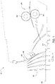
FIG. 1 is a diagrammatic view illustrating the crop leaning forward slightly for a cutting implement to cut. -
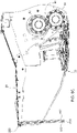
FIG. 2A is a schematic perspective view of a cutter implement including a curtain having one section. -
FIG. 2B is a schematic perspective view of a cutter implement including a curtain have multiple sections. -
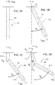
FIG. 3A is a schematic side view of a curtain before it contacts crop material. -
FIG. 3B is a schematic side view of a curtain having a bend angle at the top of the curtain when the curtain contacts crop material. -
FIG. 3C is a schematic side view of a curtain having a bend angle between the top and bottom of the curtain when the curtain contacts crop material. -
FIG. 3D is a schematic side view of a curtain having two bend angles on the top or between the top and bottom of the curtain when the curtain contacts crop material. -
FIG. 4 is a side view of the first implementation of a stiffness control feature of a curtain having variable thickness. -
FIG. 5 is a side view of the second implementation of a stiffness control feature of a curtain having variable durometer. -
FIG. 6 is a side view of the third implementation of a stiffness control feature of a curtain having multiple portions coupled to one another with different thickness. -
FIG. 7 is a side view of the fourth implementation of a stiffness control feature of a curtain having multiple layers. -
FIG. 8A is a top view of the fifth implementation of a stiffness control feature of a curtain having multiple layers, each of which include multiple strips. -
FIG. 8B is a schematic perspective view of a cutter implement having the curtain with the stiffness control feature shown inFIG. 8A . -
FIG. 8C is a partial schematic side view of the cutter implement shown inFIG. 8A . -
FIG. 8D is a partial exploded perspective view of the cutter implement shown inFIG. 8A . -
FIG. 9A . is a schematic perspective view of the sixth implementation of a stiffness control feature of a curtain. -
FIG. 9B is a side view of the stiffness control feature shown inFIG. 9A -
FIG. 9C is a partial exploded perspective view of the cutter implement shown inFIG. 9A . -
FIG. 10 is a schematic perspective view of a cutter implement having six sections with respective stiffness control features. - Referring to
FIG. 1 , acutter implement 10 include acutter 30 extending in a forward direction relative to the direction of the operation V, which is the travel direction. For clarity, ahousing 20 of thecutter implement 10 is omitted inFIG. 1 but is shown inFIGS. 2A and2B . Acutting region 28 is defined in front of thecutter 30. Optionally, acrop processor 80 is positioned rearward of the cutter relative to the direction of operation (travel) and operable to condition cutcrop material 90. Thecrop processor 80 in one implementation includes afirst conditioning roll 82 and asecond conditioning roll 84 engaging with each other to condition thecrop material 90. However, it should be appreciated that thecrop processor 80 may be implemented in another configuration not shown or described herein that is capable of processing cut crop as understood by those skilled in the art. The cutter implement 10 may include, but is not limited to, a mower and a mower-conditioner. The mower and/or mower conditioner may be drawn by a vehicle, such as but not limited to a tractor or other similar vehicle, or may be a self-propelled implement having motive power, steering systems, control systems, etc. - Leaning the
crop 90 forward may provide several benefits for crop cutting and crop conditioning process. For example, it may allow the base end of the stems to be fed into thefirst conditioning roll 82 and thesecond conditioning roll 84 as shown inFIG. 1 . Feeding the crop (material) 90 into thecrop processor 80 in this manner has shown to improve cutting performance by minimizing re-cutting at thecutter 30 and it improves cut height uniformity. However, the degree to which thecrops 90 are flexed forward greatly affects how much the performance can be improved. In fact, if thecrop 90 is over-flexed it may hinder cutting performance. - Therefore, to achieve the improvement in cutting and conditioning performance, the
crop 90 may be flexed forward "slightly" so that the stem remains intact and erect but not "over-bent" such that the stem is kinked/yielded, causing the crop to permanently tip or lay on the ground prior to being severed. In general, taller crops are typically more stiff/rigid than short crops. Therefore, a bending force required to bend rigid taller crops forward may need to be stronger than the bending force required to bend shorter more compliant crops forward. The present disclosure includes a cutter implement and a cutter apparatus, which have a stiffness control feature for a curtain operable to control a vertical stiffness of the curtain to determine the force applied to the crop. The vertical stiffness of the curtain is directly related to the resistance against bending of the curtain resulting from the pushing/reaction of thecrop material 90 acting on thecurtain 50. As shown inFIGS. 2A and2B , the cutter implement 10 may include ahousing 20, thecutter 30, and acurtain 50. Thehousing 20 includes anupper frame portion 22, a firstlateral frame portion 24, and a second lateral frame portion 26. The firstlateral frame portion 24 and the second lateral frame portion 26 are spaced apart from each other and disposed on opposing lateral sides of thehousing 20 relative to a centrallongitudinal axis 25 of thehousing 20. Thehousing 20 also has aforward end 222, included by theupper frame portion 22 in one implementation, for engaging thecrop material 90 when moving in a direction of operation V. Thehousing 20 at least partially defines the cuttingregion 28 disposed at or near theforward end 222. - The
cutter 30, as shown inFIGS. 2A and2B , is coupled to thehousing 20 and is operable to cut thecrop material 90 in the cuttingregion 28. In one implementation, thecutter 30 is configured as a cutter-bar extending laterally transverse relative to the centrallongitudinal axis 25 of thehousing 20, across a width of the cutter implement 10. - The
curtain 50 is coupled to theforward end 222 of thehousing 20 and is positioned forward of thecutter 30 relative to the direction of operation V for engaging and leaning thecrop material 90 upstream of thecutter 30, as shown inFIG. 2A and2B . Thecurtain 50 at least partially defines the cuttingregion 28. In one implementation, thecurtain 50 has one section coupled laterally to theforward end 222, as shown inFIG. 2A . In another implementation, thecurtain 50 may include multiple sections coupled laterally to theforward end 222. As shown inFIGS. 2A and2B , thecurtain 50 may include threesections middle section 502 has an offset to the other twoadjacent sections curtain 50 section by section. The implementations of thecurtain 50 described in this disclosure may be applied to single section or more than one section of thecurtain 50. Thecurtain 50 is moveable in a rearward direction relative to the direction of operation V. When the cutter implement 10 moves in the direction of operation V, thecurtain 50 contacts thecrop 90 and may be moved in the rearward direction due to the stiffness of thecrop 90. Thecrop 90 may be simultaneously flexed forward due to the force applied from thecurtain 50. The weight, material, shape, and/or other characteristic of thecurtain 50 affect the vertical stiffness of the curtain, and may bias thecurtain 50 toward its original position, which provides a resistance of thecurtain 50 against rearward movement after thecurtain 50 contacts thecrop 90. - Referring to
FIGS. 3A-3D thecurtain 50 includes astiffness control feature 60 operable to control the vertical stiffness of thecurtain 50. Thestiffness control feature 60 is operable to provide a variable vertical stiffness that increases with an increase in a bend angle θ of thecurtain 50 rearward relative to the direction of operation V. The vertical stiffness of thecurtain 50 is directly related to the resistance against bending resulting from the pushing of thecrop material 90 acting on thecurtain 50.FIGS. 3B-3D illustrate the bend angle θ, can be defined at any point at the (section of)curtain 50 relative to vertical line(s). The location and the shape of thestiffness control feature 60 shown inFIGS. 3A-3D are merely a demonstration. Thestiffness control feature 60 can be disposed inside or outside thecurtain 50 or as characteristic(s) of thecurtain 50 itself, the details of which will be described later. As shown inFIG. 3A , the vertical line L (L1) overlaps with the reference line LRef of thecurtain 50, before thecurtain 50 contacts thecrop material 90. The reference line LRef may be drawn in the middle part of the curtain for showing the extent (e.g. the bend angle θ) thecurtain 50 bends. Thecurtain 50 is hung vertically relative to a ground surface before thecurtain 50 engages thecrop material 90 and exhibits the bend angle θ substantially equal to zero. - With reference to
FIG. 3B , when thecurtain 50 as a whole is rearward, the bend angle θ between the vertical line L1 and the reference line LRef increases from zero to the bend angle θ1. The intersection P1 of the vertical line L1 and the reference line LRef is at the top of thecurtain 50. - With reference to
FIG. 3C , when anupper portion 512 of thecurtain 50 remains in the same position but alower portion 514 of thecurtain 50 is rearward, the bend angle θ between a vertical line L2 and the reference line LRef increases from zero to the bend angle θ2. The intersection P2 of the vertical line L2 and the reference line LRef is at the bottom of theupper portion 512 or the top of thelower portion 514 of thecurtain 50. - With reference to
FIG. 3D , when theupper portion 512 of thecurtain 50 and alower portion 514 of thecurtain 50 are rearward in different extents, one bend angle θ between a vertical line L3 and the reference line LRef increases from zero to the bend angle θ3, and another bend angle θ between a vertical line L4 and the reference line LRef increases from zero to the bend angle θ4. The intersection P3 of the vertical line L3 and the reference line LRef is at the top of theupper portion 512. The intersection P4 of the vertical line L4 and the reference line LRef is at the bottom of theupper portion 512 or the top of thelower portion 514 of thecurtain 50. The number of the vertical lines and intersections can be more than two, up to infinite, such as, for example, when thecurtain 50 at least partially includes a curved shape. - The configuration of the
stiffness control feature 60 shown inFIGS. 3A-3D is not limited to what it is shown. For example, thestiffness control feature 60 may have, alone or in combination, variable thickness, variable durometer, multiple portions coupled to one another with different thickness, multiple layers, multiple layers with multiple strips, and weigh element(s). -
FIG. 4 illustrates the first implementation of astiffness control feature stiffness control feature 61 includes a thickness of thecurtain 50, and the thickness of thecurtain 50 is variable in a vertical direction. The thickness of thecurtain 50 increases from a bottom of thecurtain 50 to a top of thecurtain 50, proportionally in this implementation, so as to form a slope on aforward surface 612 operable to engage thecrop material 90. Therearward surface 614, the opposite surface of theforward surface 612, may be vertical to the ground surface. - Referring to
FIG. 5 illustrates the second implementation of astiffness control feature stiffness control feature 62 of thecurtain 50 has variable durometer, the higher portion of thecurtain 50, the greater of durometer. For example, anupper portion 622 of thecurtain 50 has greater durometer than does alower portion 624 of thecurtain 50. Therefore, thestiffness control feature 62 is operable to increase the vertical stiffness of thecurtain 50 from a bottom of thecurtain 50 to a top of thecurtain 50. - Referring to
FIG. 6 illustrates the third implementation of astiffness control feature curtain 50 having multiple portions coupled to one another with different thickness. Thestiffness control feature 63 ofcurtain 50 includes afirst portion 632, asecond portion 634 coupled to a lower part of thefirst portion 632, and athird portion 636 coupled to a lower part of thesecond portion 634. Thecurtain 50 may be made by one-piece (not shown), with a thickness of thefirst portion 632 is greater than a thickness of thesecond portion 634, and the thickness of thesecond portion 634 is greater than a thickness of thethird portion 636. Alternatively, thestiffness control feature 63 may include multiple layers with different height stacking together to form thefirst portion 632,second portion 634, and thethird portion 636. - Referring to
FIG. 7 illustrates the fourth implementation of astiffness control feature curtain 50 having multiple layers. The number of the layers in the fourth implementation is four but it may be any number of layers. Thestiffness control feature 64 includes afirst layer 642, asecond layer 644 disposed rearward of thefirst layer 642 relative to the direction of operation V, athird layer 646 disposed rearward of thesecond layer 644 relative to the direction of operation V, and afourth layer 648 disposed rearward of thethird layer 646 relative to the direction of operation V. The first, second, third,fourth layers curtain 50 when thecurtain 50 is in response to thefirst layer 642 moving in the rearward direction and engaging thesecond layer 644, thesecond layer 644 moving in the rearward direction and engaging thethird layer 646, thethird layer 646 moving in the rearward direction and engaging thefourth layer 648, with an increase of the bend angle θ. The heights of the multiple layers (the first, second, third,fourth layers first layer 642 to the fourth layers 648. For instance, the height of thefirst layer 642 is longer than a height of thesecond layer 644. The rearward layers such as thethird layer 646 and thefourth layer 648 will only bend when thecurtain 50 leans high crop material (usually stiffer than short crop material) forward. The thickness of the multiple layers (the first, second, third,fourth layers first layer 642 to thefourth layer 648. For instance, a thickness of thesecond layer 644 is greater than a thickness of thefirst layer 642. With forward layer longer and thinner than rearward layer, such arrangement may provide more consistent vertical stiffness increase with the increasing bend angle θ, so as to provide more consistent increasing force to lean thecrop material 90 forward. However the present disclosure also includes an implementation that may have forward layers shorter and/or thicker than rearward layers, or any other variation. - The distances between the layers may be different. In one implementation, the distance between layers may increase. For instance, a distance between the
second layer 644 and thethird layer 646 is greater than a distance between thefirst layer 642 and thesecond layer 644. In that arrangement, the time thefirst layer 642 gets influenced by thesecond layer 644 is shorter than the time thefirst layer 642 andsecond layer 644 get influenced by thethird layer 646, and the stiffness of thecurtain 50 changes in different extent during the course of bending partially determined by the distance between layers. Spacing the multiple layers (the first, second, third,fourth layers -
FIGS. 8A-8D illustrates the fifth implementation of astiffness control feature curtain 50 having multiple layers, each of which include multiple strips. The number of the layers in the fifth implementation is three but it may be any other multiple number. Thestiffness control feature 65 includes afirst layer 652, asecond layer 654 disposed rearward of thefirst layer 652 relative to the direction of operation V, and athird layer 656 disposed rearward of thesecond layer 654 relative to the direction of operation V. The first, second andthird layers curtain 50 when thecurtain 50 is in response to thefirst layer 652 moving in the rearward direction and engaging thesecond layer 654 and thesecond layer 654 moving in the rearward direction and engaging thethird layer 656, with an increase of the bend angle θ. As shown inFIG. 8C , the thickness of the layers increase from thefirst layer 652 to thethird layer 656. Thefirst layer 652 includes a row offirst strips 653 disposed laterally relative to a centrallongitudinal axis 25 of thehousing 20, thesecond layer 654 includes a row ofsecond strips 655 disposed laterally relative to the centrallongitudinal axis 25 of thehousing 20, and thethird layer 656 includes a row ofthird strips 657 disposed laterally relative to the centrallongitudinal axis 25 of thehousing 20. Each respective one of thefirst strips 653 has a first width, each respective one of thesecond strips 655 has a second width, and each respective one of thethird strips 657 has a third width. The first width is greater than the second width and the second width is greater than the third width. The at least one of thesecond strips 655 is operable to overlap two adjacentfirst strips 653 so as to cover a space between the two adjacentfirst strips 653 in the lateral direction. -
FIGS. 9A-9C illustrates the sixth implementation of astiffness control feature stiffness control feature curtain 50 includesweight elements 662 attached to thecurtain 50. As shown inFIG. 9C , thecurtain 50 has three sections in this implementation and therefore an offset of the curtain in the direction of operation V is shown inFIG. 9B . Theweight elements 662 are operable to at least partially change the stiffness of thecurtain 50 and to increase the resistance against bending of thecurtain 50 when thecurtain 50 engagescrop material 90. It is noted that theweight elements 662 can be arranged on the forward or rearward surface, or both. The location of theweight elements 662 can be determined depending on the needs. Theweight elements 662 attach to thecurtain 50 via fasteners such as screw, nuts and bolt, or adhesive agent. Changing theweight elements 662 on a segment of thecurtain 50 can be performed by replacing them with another weight ofweight elements 662 or replacing the section they attached to with another segment of thecurtain 50 having different weight elements 662 (different from the number, weight, and locations, for example.) -
FIG. 10 is a schematic perspective view of a cutter implement 10 having seven sections with respective stiffness control features 61, 62, 63, 64, 65, 66. The order and number of the segments with different stiffness control features 61, 62, 63, 64, 65, 66 can be changed depending on the needs. - The present disclosure curtain apparatus having the
curtain 50 for a cutter implement 10. Thecurtain 50 may include one or multiple sections. Thecurtain 50 may include one or more stiffness control feature 60 (61, 62, 63, 64, 65, 66) as described previously. - Without in any way limiting the scope, interpretation, or application of the claims appearing below, a technical effect of one or more of the example embodiments disclosed herein is to provide stiffness control feature(s) control a vertical stiffness of the curtain to change the resistance of the curtain to lean the crop material in a forward direction relative to the direction of operation, so as to obtain a better cutting or crop processing results. Another technical effect of one or more of the example embodiments disclosed herein is the aforementioned stiffness control feature(s) coupled to or included by the curtain is operable to be replaced by different stiffness control feature, or the (section of) curtain with the stiffness control feature is operable to be replaced by another (section of) curtain together with different stiffness control feature, such that the entire curtain or some sections of the curtain can adjust the resistance on the crop, leaning the crop in a preferable extent for cutting and processing the crop material.
- While the above describes example embodiments of the present disclosure, these descriptions should not be viewed in a limiting sense. Rather, other variations and modifications may be made without departing from the scope and spirit of the present disclosure as defined in the appended claims.
Claims (15)
- A cutter implement (10) for cutting crop material (90), the cutter implement (10) comprising:a housing (20) having a forward end (222) for engaging the crop material (90) when moving in a direction of operation (V), wherein the housing (20) at least partially defines a cutting region (28) disposed at the forward end (222) thereof;a cutter (30) coupled to the housing (20) and operable to cut the crop material (90) in the cutting region (28);a curtain (50) coupled to the forward end (222) of the housing (20) and positioned forward of the cutter (30) relative to the direction of operation for engaging and leaning the crop material (90) upstream of the cutter (30), wherein the curtain (50) includes a stiffness control feature (60, 61, 62, 63, 64, 65, 66) operable to control a vertical stiffness of the curtain (50) to provide a variable vertical stiffness that increases with an increase in a bend angle of the curtain (50) rearward relative to the direction of operation (V).
- The cutter implement (10) set forth in claim 1, wherein the stiffness control feature (60, 61) includes a thickness of the curtain (50), wherein the thickness of the curtain (50) is variable in a vertical direction.
- The cutter implement (10) set forth in claim 1 or 2, wherein the thickness of the curtain (50) increases from a bottom of the curtain (50) to a top of the curtain (50).
- The cutter implement (10) according to at least one of the claims 1 to 3, wherein the thickness of the curtain (50) increases proportionally, so as to form a slope operable to engage the crop material (90).
- The cutter implement (10) according to at least one of the claims 1 to 4, wherein the stiffness control feature (60, 62) is configured to increase the vertical stiffness of the curtain (50) from a bottom of the curtain (50) to a top of the curtain (50).
- The cutter implement (10) according to at least one of the claims 1 to 5, wherein the curtain (50) is hung vertically relative to a ground surface before the curtain (50) engages the crop material (90) and exhibits the bend angle substantially equal to zero.
- The cutter implement (10) according to at least one of the claims 1 to 6, wherein the stiffness control feature (60, 64) includes a first layer (642, 652) and a second layer (644, 654) disposed rearward of the first layer (642, 652) relative to the direction of operation (V) and configured to increase the vertical stiffness of the curtain (50) when the curtain (50) is in response to the first layer (642, 652) moving in a rearward direction and engaging the second layer (644, 654).
- The cutter implement (10) according to at least one of the claims 1 to 7, wherein a height of the first layer (642) is different from a height of the second layer (644).
- The cutter implement (10) according to at least one of the claims 1 to 8, wherein a thickness of the second layer (644) is different from a thickness of the first layer (642).
- The cutter implement (10) according to at least one of the claims 1 to 9, wherein the first layer (652) includes a row of first strips (653) disposed laterally relative to a central longitudinal axis (25) of the housing (20), and the second layer (654) includes a row of second strips (655) disposed laterally relative to the central longitudinal axis (25) of the housing (20).
- The cutter implement (10) according to at least one of the claims 1 to 10, wherein the row of first strips (653) includes a plurality of first strips (653), with each respective one of the plurality of first strips (653) having a first width, and the row of second strips (655) includes a plurality of second strips (655), with each respective one of the plurality of second strips (655) having a second width, wherein the first width is greater than the second width.
- The cutter implement (10) according to at least one of the claims 1 to 11, wherein at least one of the second strips (655) is operable to overlap two adjacent first strips (653) so as to cover a space between the two adjacent first strips (653).
- The cutter implement (10) according to at least one of the claims 1 to 12, wherein the curtain (50) includes a first portion (632) and a second portion (634) coupled to a lower part of the first portion (632), and a thickness of the first portion (632) is greater than a thickness of the second portion (634).
- The cutter implement (10) according to at least one of the claims 1 to 13, wherein the stiffness control feature (60, 66) includes a weight element (662) attached to the curtain (50), wherein the weight element (662) is operable to at least partially change the stiffness of the curtain (50) and to increase a resistance against bending of the curtain (50) when the curtain (50) engages crop material (90).
- A curtain apparatus for a cutter implement (10), in particular for a cutter implement (10) according to at least one of the claims 1 to 14, comprising:
a curtain (50) operable to be coupled to the cutter implement (10), wherein the curtain (50) includes a stiffness control feature (60, 61, 62, 63, 64, 65, 66) operable to control a vertical stiffness of the curtain (50) to provide a variable vertical stiffness that increases with an increase in a bend angle of the curtain (50) rearward relative to a direction of operation (V).
Applications Claiming Priority (1)
| Application Number | Priority Date | Filing Date | Title |
|---|---|---|---|
| US17/070,395 US11771005B2 (en) | 2020-10-14 | 2020-10-14 | Cutter implement with curtain |
Publications (3)
| Publication Number | Publication Date |
|---|---|
| EP3984343A2 true EP3984343A2 (en) | 2022-04-20 |
| EP3984343A3 EP3984343A3 (en) | 2022-12-07 |
| EP3984343B1 EP3984343B1 (en) | 2025-04-23 |
Family
ID=80685608
Family Applications (1)
| Application Number | Title | Priority Date | Filing Date |
|---|---|---|---|
| EP21200670.4A Active EP3984343B1 (en) | 2020-10-14 | 2021-10-04 | Cutter implement with curtain |
Country Status (2)
| Country | Link |
|---|---|
| US (1) | US11771005B2 (en) |
| EP (1) | EP3984343B1 (en) |
Families Citing this family (1)
| Publication number | Priority date | Publication date | Assignee | Title |
|---|---|---|---|---|
| US11785891B2 (en) * | 2020-10-14 | 2023-10-17 | Deere & Company | Cutter implement having a crop pushing system |
Family Cites Families (14)
| Publication number | Priority date | Publication date | Assignee | Title |
|---|---|---|---|---|
| US3027701A (en) * | 1959-09-29 | 1962-04-03 | Sperry Rand Corp | Forage harvester |
| US3306015A (en) | 1964-08-04 | 1967-02-28 | Deere & Co | Safety curtain for farm implements |
| GB1462864A (en) * | 1973-05-21 | 1977-01-26 | Sperry Rand France | Rotary mowers |
| GB2005523B (en) | 1977-10-07 | 1982-04-15 | Samibem Sa | Haymaking machine |
| DE3039594C2 (en) * | 1980-10-21 | 1985-03-07 | Albert Reiff Kg, 7410 Reutlingen | Louvre door made of strips of flexible plastic material |
| US4539798A (en) * | 1982-03-26 | 1985-09-10 | National Research Development Corporation | Apparatus and method for conveying and/or treating crop |
| US4499711A (en) * | 1984-03-02 | 1985-02-19 | Sperry Corporation | Deflector panel for disc mower-conditioner |
| US4729212A (en) * | 1986-09-18 | 1988-03-08 | Rabitsch Thermon D | Protective cover for combine skid plates |
| AU9427598A (en) * | 1998-03-31 | 1999-10-18 | Xingan Chen | A thresher for rice and wheat standing in the field and a harvester using the thresher |
| DE29808478U1 (en) * | 1998-05-11 | 1998-07-23 | Mulag Fahrzeugwerk Heinz Wössner GmbH u. Co KG, 77740 Bad Peterstal-Griesbach | Anti-skid protection with swing flaps |
| CA2272198A1 (en) | 1999-05-19 | 2000-11-19 | Schulte Industries Ltd. | Chain guard |
| US7644566B2 (en) | 2008-04-04 | 2010-01-12 | Cnh America Llc | Curtain to direct crop in a header |
| US7644567B2 (en) | 2008-05-01 | 2010-01-12 | Cnh America Llc | Flexible tall crop pusher |
| US7980049B1 (en) | 2010-09-29 | 2011-07-19 | Cnh America Llc | Twin sheet vacuum formed covers for disc mower cutterbars |
-
2020
- 2020-10-14 US US17/070,395 patent/US11771005B2/en active Active
-
2021
- 2021-10-04 EP EP21200670.4A patent/EP3984343B1/en active Active
Also Published As
| Publication number | Publication date |
|---|---|
| US20220110261A1 (en) | 2022-04-14 |
| EP3984343B1 (en) | 2025-04-23 |
| US11771005B2 (en) | 2023-10-03 |
| EP3984343A3 (en) | 2022-12-07 |
Similar Documents
| Publication | Publication Date | Title |
|---|---|---|
| US6029429A (en) | Header for a crop harvesting machine with adjustment of a longitudinal shape of the cutter bar | |
| US6883299B1 (en) | Height sensor arrangement for agricultural applications | |
| US8806846B2 (en) | Stem deflector | |
| US20230240185A1 (en) | Apparatus, Systems And Methods For Eliminating Cross-Track Error | |
| EP3984343B1 (en) | Cutter implement with curtain | |
| US6865871B2 (en) | Crop feed arrangement for the header of a combine harvester | |
| US10582658B2 (en) | Light beam header height control system for an agricultural harvester | |
| US11582904B2 (en) | Multi-segmented deck plate auto adjustment mechanism for a harvester row unit | |
| US20020069628A1 (en) | Sensor arm for combine header | |
| US12457937B2 (en) | Crop harvesting header with variable diameter reel | |
| EP2862432A1 (en) | Header height sensor | |
| EP3897094B1 (en) | Arm assembly of an agricultural header | |
| US4147016A (en) | Harvester having height adjustable head | |
| US11564351B2 (en) | Lawn striping mechanism | |
| EP3669636B1 (en) | A split reel combine header | |
| US11785891B2 (en) | Cutter implement having a crop pushing system | |
| JP6521790B2 (en) | Harvester | |
| US11272668B2 (en) | Adjustable duct for a combine harvester cleaning fan | |
| US20210227750A1 (en) | Agricultural Harvester with Header Having Conformable Portions | |
| US4550555A (en) | Crop guiding attachment for a combine divider | |
| CN1742540A (en) | Harvester steering probe assembly | |
| EP3711472B1 (en) | Sensor arm | |
| US7980049B1 (en) | Twin sheet vacuum formed covers for disc mower cutterbars | |
| EP4544899A1 (en) | Agricultural system and method for accounting for hill-drift steering during row guidance of harvesters | |
| JP2550611Y2 (en) | Cutting part ear part guide plate of combine |
Legal Events
| Date | Code | Title | Description |
|---|---|---|---|
| PUAI | Public reference made under article 153(3) epc to a published international application that has entered the european phase |
Free format text: ORIGINAL CODE: 0009012 |
|
| STAA | Information on the status of an ep patent application or granted ep patent |
Free format text: STATUS: THE APPLICATION HAS BEEN PUBLISHED |
|
| AK | Designated contracting states |
Kind code of ref document: A2 Designated state(s): AL AT BE BG CH CY CZ DE DK EE ES FI FR GB GR HR HU IE IS IT LI LT LU LV MC MK MT NL NO PL PT RO RS SE SI SK SM TR |
|
| PUAL | Search report despatched |
Free format text: ORIGINAL CODE: 0009013 |
|
| AK | Designated contracting states |
Kind code of ref document: A3 Designated state(s): AL AT BE BG CH CY CZ DE DK EE ES FI FR GB GR HR HU IE IS IT LI LT LU LV MC MK MT NL NO PL PT RO RS SE SI SK SM TR |
|
| RIC1 | Information provided on ipc code assigned before grant |
Ipc: A01D 57/22 20060101ALI20221028BHEP Ipc: A01D 34/66 20060101ALI20221028BHEP Ipc: A01D 75/20 20060101ALI20221028BHEP Ipc: A01D 34/62 20060101ALI20221028BHEP Ipc: A01D 34/42 20060101AFI20221028BHEP |
|
| STAA | Information on the status of an ep patent application or granted ep patent |
Free format text: STATUS: REQUEST FOR EXAMINATION WAS MADE |
|
| 17P | Request for examination filed |
Effective date: 20230607 |
|
| RBV | Designated contracting states (corrected) |
Designated state(s): AL AT BE BG CH CY CZ DE DK EE ES FI FR GB GR HR HU IE IS IT LI LT LU LV MC MK MT NL NO PL PT RO RS SE SI SK SM TR |
|
| GRAP | Despatch of communication of intention to grant a patent |
Free format text: ORIGINAL CODE: EPIDOSNIGR1 |
|
| STAA | Information on the status of an ep patent application or granted ep patent |
Free format text: STATUS: GRANT OF PATENT IS INTENDED |
|
| INTG | Intention to grant announced |
Effective date: 20241219 |
|
| GRAS | Grant fee paid |
Free format text: ORIGINAL CODE: EPIDOSNIGR3 |
|
| GRAA | (expected) grant |
Free format text: ORIGINAL CODE: 0009210 |
|
| STAA | Information on the status of an ep patent application or granted ep patent |
Free format text: STATUS: THE PATENT HAS BEEN GRANTED |
|
| AK | Designated contracting states |
Kind code of ref document: B1 Designated state(s): AL AT BE BG CH CY CZ DE DK EE ES FI FR GB GR HR HU IE IS IT LI LT LU LV MC MK MT NL NO PL PT RO RS SE SI SK SM TR |
|
| REG | Reference to a national code |
Ref country code: GB Ref legal event code: FG4D |
|
| REG | Reference to a national code |
Ref country code: CH Ref legal event code: EP |
|
| REG | Reference to a national code |
Ref country code: DE Ref legal event code: R096 Ref document number: 602021029516 Country of ref document: DE |
|
| REG | Reference to a national code |
Ref country code: IE Ref legal event code: FG4D |
|
| REG | Reference to a national code |
Ref country code: NL Ref legal event code: MP Effective date: 20250423 |
|
| PG25 | Lapsed in a contracting state [announced via postgrant information from national office to epo] |
Ref country code: NL Free format text: LAPSE BECAUSE OF FAILURE TO SUBMIT A TRANSLATION OF THE DESCRIPTION OR TO PAY THE FEE WITHIN THE PRESCRIBED TIME-LIMIT Effective date: 20250423 |
|
| REG | Reference to a national code |
Ref country code: AT Ref legal event code: MK05 Ref document number: 1786813 Country of ref document: AT Kind code of ref document: T Effective date: 20250423 |
|
| PG25 | Lapsed in a contracting state [announced via postgrant information from national office to epo] |
Ref country code: PT Free format text: LAPSE BECAUSE OF FAILURE TO SUBMIT A TRANSLATION OF THE DESCRIPTION OR TO PAY THE FEE WITHIN THE PRESCRIBED TIME-LIMIT Effective date: 20250825 Ref country code: FI Free format text: LAPSE BECAUSE OF FAILURE TO SUBMIT A TRANSLATION OF THE DESCRIPTION OR TO PAY THE FEE WITHIN THE PRESCRIBED TIME-LIMIT Effective date: 20250423 Ref country code: ES Free format text: LAPSE BECAUSE OF FAILURE TO SUBMIT A TRANSLATION OF THE DESCRIPTION OR TO PAY THE FEE WITHIN THE PRESCRIBED TIME-LIMIT Effective date: 20250423 |
|
| REG | Reference to a national code |
Ref country code: LT Ref legal event code: MG9D |
|
| PG25 | Lapsed in a contracting state [announced via postgrant information from national office to epo] |
Ref country code: GR Free format text: LAPSE BECAUSE OF FAILURE TO SUBMIT A TRANSLATION OF THE DESCRIPTION OR TO PAY THE FEE WITHIN THE PRESCRIBED TIME-LIMIT Effective date: 20250724 Ref country code: NO Free format text: LAPSE BECAUSE OF FAILURE TO SUBMIT A TRANSLATION OF THE DESCRIPTION OR TO PAY THE FEE WITHIN THE PRESCRIBED TIME-LIMIT Effective date: 20250723 |
|
| PG25 | Lapsed in a contracting state [announced via postgrant information from national office to epo] |
Ref country code: PL Free format text: LAPSE BECAUSE OF FAILURE TO SUBMIT A TRANSLATION OF THE DESCRIPTION OR TO PAY THE FEE WITHIN THE PRESCRIBED TIME-LIMIT Effective date: 20250423 |
|
| PG25 | Lapsed in a contracting state [announced via postgrant information from national office to epo] |
Ref country code: BG Free format text: LAPSE BECAUSE OF FAILURE TO SUBMIT A TRANSLATION OF THE DESCRIPTION OR TO PAY THE FEE WITHIN THE PRESCRIBED TIME-LIMIT Effective date: 20250423 |
|
| PG25 | Lapsed in a contracting state [announced via postgrant information from national office to epo] |
Ref country code: HR Free format text: LAPSE BECAUSE OF FAILURE TO SUBMIT A TRANSLATION OF THE DESCRIPTION OR TO PAY THE FEE WITHIN THE PRESCRIBED TIME-LIMIT Effective date: 20250423 |
|
| PG25 | Lapsed in a contracting state [announced via postgrant information from national office to epo] |
Ref country code: AT Free format text: LAPSE BECAUSE OF FAILURE TO SUBMIT A TRANSLATION OF THE DESCRIPTION OR TO PAY THE FEE WITHIN THE PRESCRIBED TIME-LIMIT Effective date: 20250423 |
|
| PG25 | Lapsed in a contracting state [announced via postgrant information from national office to epo] |
Ref country code: RS Free format text: LAPSE BECAUSE OF FAILURE TO SUBMIT A TRANSLATION OF THE DESCRIPTION OR TO PAY THE FEE WITHIN THE PRESCRIBED TIME-LIMIT Effective date: 20250723 |
|
| PG25 | Lapsed in a contracting state [announced via postgrant information from national office to epo] |
Ref country code: IS Free format text: LAPSE BECAUSE OF FAILURE TO SUBMIT A TRANSLATION OF THE DESCRIPTION OR TO PAY THE FEE WITHIN THE PRESCRIBED TIME-LIMIT Effective date: 20250823 |
|
| PG25 | Lapsed in a contracting state [announced via postgrant information from national office to epo] |
Ref country code: LV Free format text: LAPSE BECAUSE OF FAILURE TO SUBMIT A TRANSLATION OF THE DESCRIPTION OR TO PAY THE FEE WITHIN THE PRESCRIBED TIME-LIMIT Effective date: 20250423 |
|
| PGFP | Annual fee paid to national office [announced via postgrant information from national office to epo] |
Ref country code: DE Payment date: 20250919 Year of fee payment: 5 |
|
| PGFP | Annual fee paid to national office [announced via postgrant information from national office to epo] |
Ref country code: GB Payment date: 20251027 Year of fee payment: 5 |
|
| PG25 | Lapsed in a contracting state [announced via postgrant information from national office to epo] |
Ref country code: SM Free format text: LAPSE BECAUSE OF FAILURE TO SUBMIT A TRANSLATION OF THE DESCRIPTION OR TO PAY THE FEE WITHIN THE PRESCRIBED TIME-LIMIT Effective date: 20250423 Ref country code: DK Free format text: LAPSE BECAUSE OF FAILURE TO SUBMIT A TRANSLATION OF THE DESCRIPTION OR TO PAY THE FEE WITHIN THE PRESCRIBED TIME-LIMIT Effective date: 20250423 |
|
| PGFP | Annual fee paid to national office [announced via postgrant information from national office to epo] |
Ref country code: FR Payment date: 20251027 Year of fee payment: 5 |
|
| PG25 | Lapsed in a contracting state [announced via postgrant information from national office to epo] |
Ref country code: CZ Free format text: LAPSE BECAUSE OF FAILURE TO SUBMIT A TRANSLATION OF THE DESCRIPTION OR TO PAY THE FEE WITHIN THE PRESCRIBED TIME-LIMIT Effective date: 20250423 |
|
| PG25 | Lapsed in a contracting state [announced via postgrant information from national office to epo] |
Ref country code: EE Free format text: LAPSE BECAUSE OF FAILURE TO SUBMIT A TRANSLATION OF THE DESCRIPTION OR TO PAY THE FEE WITHIN THE PRESCRIBED TIME-LIMIT Effective date: 20250423 |
|
| REG | Reference to a national code |
Ref country code: DE Ref legal event code: R097 Ref document number: 602021029516 Country of ref document: DE |
|
| PG25 | Lapsed in a contracting state [announced via postgrant information from national office to epo] |
Ref country code: RO Free format text: LAPSE BECAUSE OF FAILURE TO SUBMIT A TRANSLATION OF THE DESCRIPTION OR TO PAY THE FEE WITHIN THE PRESCRIBED TIME-LIMIT Effective date: 20250423 Ref country code: SK Free format text: LAPSE BECAUSE OF FAILURE TO SUBMIT A TRANSLATION OF THE DESCRIPTION OR TO PAY THE FEE WITHIN THE PRESCRIBED TIME-LIMIT Effective date: 20250423 |
|
| PG25 | Lapsed in a contracting state [announced via postgrant information from national office to epo] |
Ref country code: IT Free format text: LAPSE BECAUSE OF FAILURE TO SUBMIT A TRANSLATION OF THE DESCRIPTION OR TO PAY THE FEE WITHIN THE PRESCRIBED TIME-LIMIT Effective date: 20250423 |
|
| PLBE | No opposition filed within time limit |
Free format text: ORIGINAL CODE: 0009261 |
|
| STAA | Information on the status of an ep patent application or granted ep patent |
Free format text: STATUS: NO OPPOSITION FILED WITHIN TIME LIMIT |
|
| REG | Reference to a national code |
Ref country code: CH Ref legal event code: L10 Free format text: ST27 STATUS EVENT CODE: U-0-0-L10-L00 (AS PROVIDED BY THE NATIONAL OFFICE) Effective date: 20260304 |
|
| 26N | No opposition filed |
Effective date: 20260126 |