EP3983855B1 - Automatic calculation of measurement confidence in flexible modular plants and machines - Google Patents
Automatic calculation of measurement confidence in flexible modular plants and machines Download PDFInfo
- Publication number
- EP3983855B1 EP3983855B1 EP20746891.9A EP20746891A EP3983855B1 EP 3983855 B1 EP3983855 B1 EP 3983855B1 EP 20746891 A EP20746891 A EP 20746891A EP 3983855 B1 EP3983855 B1 EP 3983855B1
- Authority
- EP
- European Patent Office
- Prior art keywords
- modular
- uncertainty
- output value
- entities
- value
- Prior art date
- Legal status (The legal status is an assumption and is not a legal conclusion. Google has not performed a legal analysis and makes no representation as to the accuracy of the status listed.)
- Active
Links
Images


Classifications
-
- G—PHYSICS
- G05—CONTROLLING; REGULATING
- G05B—CONTROL OR REGULATING SYSTEMS IN GENERAL; FUNCTIONAL ELEMENTS OF SUCH SYSTEMS; MONITORING OR TESTING ARRANGEMENTS FOR SUCH SYSTEMS OR ELEMENTS
- G05B19/00—Program-control systems
- G05B19/02—Program-control systems electric
- G05B19/418—Total factory control, i.e. centrally controlling a plurality of machines, e.g. direct or distributed numerical control [DNC], flexible manufacturing systems [FMS], integrated manufacturing systems [IMS] or computer integrated manufacturing [CIM]
- G05B19/41845—Total factory control, i.e. centrally controlling a plurality of machines, e.g. direct or distributed numerical control [DNC], flexible manufacturing systems [FMS], integrated manufacturing systems [IMS] or computer integrated manufacturing [CIM] characterised by system universality, reconfigurability, modularity
-
- G—PHYSICS
- G05—CONTROLLING; REGULATING
- G05B—CONTROL OR REGULATING SYSTEMS IN GENERAL; FUNCTIONAL ELEMENTS OF SUCH SYSTEMS; MONITORING OR TESTING ARRANGEMENTS FOR SUCH SYSTEMS OR ELEMENTS
- G05B19/00—Program-control systems
- G05B19/02—Program-control systems electric
- G05B19/04—Program control other than numerical control, i.e. in sequence controllers or logic controllers
- G05B19/042—Program control other than numerical control, i.e. in sequence controllers or logic controllers using digital processors
- G05B19/0426—Programming the control sequence
-
- G—PHYSICS
- G05—CONTROLLING; REGULATING
- G05B—CONTROL OR REGULATING SYSTEMS IN GENERAL; FUNCTIONAL ELEMENTS OF SUCH SYSTEMS; MONITORING OR TESTING ARRANGEMENTS FOR SUCH SYSTEMS OR ELEMENTS
- G05B19/00—Program-control systems
- G05B19/02—Program-control systems electric
- G05B19/04—Program control other than numerical control, i.e. in sequence controllers or logic controllers
- G05B19/05—Programmable logic controllers, e.g. simulating logic interconnections of signals according to ladder diagrams or function charts
- G05B19/056—Programming the PLC
-
- G—PHYSICS
- G05—CONTROLLING; REGULATING
- G05B—CONTROL OR REGULATING SYSTEMS IN GENERAL; FUNCTIONAL ELEMENTS OF SUCH SYSTEMS; MONITORING OR TESTING ARRANGEMENTS FOR SUCH SYSTEMS OR ELEMENTS
- G05B2219/00—Program-control systems
- G05B2219/20—Pc systems
- G05B2219/25—Pc structure of the system
- G05B2219/25428—Field device
-
- G—PHYSICS
- G05—CONTROLLING; REGULATING
- G05B—CONTROL OR REGULATING SYSTEMS IN GENERAL; FUNCTIONAL ELEMENTS OF SUCH SYSTEMS; MONITORING OR TESTING ARRANGEMENTS FOR SUCH SYSTEMS OR ELEMENTS
- G05B2219/00—Program-control systems
- G05B2219/30—Nc systems
- G05B2219/31—From computer integrated manufacturing till monitoring
- G05B2219/31211—Communicate diagnostic data from intelligent field device controller to central
-
- G—PHYSICS
- G05—CONTROLLING; REGULATING
- G05B—CONTROL OR REGULATING SYSTEMS IN GENERAL; FUNCTIONAL ELEMENTS OF SUCH SYSTEMS; MONITORING OR TESTING ARRANGEMENTS FOR SUCH SYSTEMS OR ELEMENTS
- G05B2219/00—Program-control systems
- G05B2219/30—Nc systems
- G05B2219/32—Operator till task planning
- G05B2219/32368—Quality control
-
- G—PHYSICS
- G05—CONTROLLING; REGULATING
- G05B—CONTROL OR REGULATING SYSTEMS IN GENERAL; FUNCTIONAL ELEMENTS OF SUCH SYSTEMS; MONITORING OR TESTING ARRANGEMENTS FOR SUCH SYSTEMS OR ELEMENTS
- G05B2219/00—Program-control systems
- G05B2219/30—Nc systems
- G05B2219/33—Director till display
- G05B2219/33046—Forward propagation error
-
- G—PHYSICS
- G05—CONTROLLING; REGULATING
- G05B—CONTROL OR REGULATING SYSTEMS IN GENERAL; FUNCTIONAL ELEMENTS OF SUCH SYSTEMS; MONITORING OR TESTING ARRANGEMENTS FOR SUCH SYSTEMS OR ELEMENTS
- G05B2219/00—Program-control systems
- G05B2219/30—Nc systems
- G05B2219/37—Measurements
- G05B2219/37325—Multisensor integration, fusion, redundant
-
- G—PHYSICS
- G06—COMPUTING OR CALCULATING; COUNTING
- G06Q—INFORMATION AND COMMUNICATION TECHNOLOGY [ICT] SPECIALLY ADAPTED FOR ADMINISTRATIVE, COMMERCIAL, FINANCIAL, MANAGERIAL OR SUPERVISORY PURPOSES; SYSTEMS OR METHODS SPECIALLY ADAPTED FOR ADMINISTRATIVE, COMMERCIAL, FINANCIAL, MANAGERIAL OR SUPERVISORY PURPOSES, NOT OTHERWISE PROVIDED FOR
- G06Q50/00—Information and communication technology [ICT] specially adapted for implementation of business processes of specific business sectors, e.g. utilities or tourism
- G06Q50/04—Manufacturing
-
- Y—GENERAL TAGGING OF NEW TECHNOLOGICAL DEVELOPMENTS; GENERAL TAGGING OF CROSS-SECTIONAL TECHNOLOGIES SPANNING OVER SEVERAL SECTIONS OF THE IPC; TECHNICAL SUBJECTS COVERED BY FORMER USPC CROSS-REFERENCE ART COLLECTIONS [XRACs] AND DIGESTS
- Y02—TECHNOLOGIES OR APPLICATIONS FOR MITIGATION OR ADAPTATION AGAINST CLIMATE CHANGE
- Y02P—CLIMATE CHANGE MITIGATION TECHNOLOGIES IN THE PRODUCTION OR PROCESSING OF GOODS
- Y02P90/00—Enabling technologies with a potential contribution to greenhouse gas [GHG] emissions mitigation
- Y02P90/30—Computing systems specially adapted for manufacturing
Definitions
- the invention relates to a method and a device for providing output values with associated uncertainties for a flexible modular plant or machine.
- Manufacturing plants based on modular entities is beneficial with regard to an increased flexibility in plant arrangement, a reduction of safety concerns during construction of the modular plant and with regard to easier modification and replacement of modular entities.
- the modular entities or equipment of such flexible modular plants may comprise components such as electrical wiring, walls, pipes, machines, actuators and sensors.
- the modular entities are installed according to a certain arrangement which describes the way in which the modular entities are connected to each other.
- Sensors can measure physical and chemical properties and provide measurement data which is afflicted with measurement uncertainties.
- the degree and type of uncertainty can be specified in the documentation of the respective sensor and may be certified by appropriate authorities.
- SCADA Supervisory Control and Data Acquisition
- MOM Manufacturing Operation Management
- MES Manufacturing Execution System
- the invention provides a method for providing output values with associated uncertainties for a flexible modular plant or machine comprising an arrangement of modular entities.
- uncertainty information is assigned, associated with the operation of the respective modular entity.
- the plurality of modular entities provides input values, wherein each input value is based on an operation of the respective modular entity of the plurality of modular entities.
- a computing unit calculates an output value based on the input values provided by the plurality of modular entities.
- the computing unit calculates an input value uncertainty for each input value based on the uncertainty information of the modular entity which has provided the input value.
- the computing unit calculates at least one output value uncertainty or confidence associated with the output value based on propagation of uncertainty and using the input value uncertainties.
- the output value and the at least one output value uncertainty are provided as output.
- the invention further provides a device for providing output values with associated uncertainties for a flexible modular plant or machine.
- the flexible modular plant or machine comprises an arrangement of modular entities. To each modular entity of a plurality of said modular entities, uncertainty information is assigned associated with an operation of the respective modular entity.
- the device comprises an interface and a computing unit.
- the interface is adapted to receive, by the plurality of modular entities, input values based on an operation of the plurality of modular entities.
- the computing unit calculates an output value based on the input values provided by the plurality of modular entities.
- the computing unit further calculates an input value uncertainty for each input value based on the uncertainty information of the modular entity that has provided the input value.
- the computing unit is further adapted to calculate at least one output value uncertainty associated with the output value based on propagation of uncertainty using the input value uncertainties.
- the interface is adapted to output the output value and the at least one output value uncertainty.
- the computing unit can provide an automatic calculation of the output value uncertainties by means of propagation of uncertainty. If the arrangement of modular entities changes, for instance by adding or removing modular entities or by arranging the modular entities in a different way, the updated uncertainty information of the modular entities according to the new arrangement is provided to the computing unit. The computing unit may therefore calculate updated output value uncertainties based on the new arrangement of the modular entities.
- the computing unit calculates the output value and/or the output value uncertainty based on the arrangement of the modular entities. If the arrangement of modular entities changes, the output unit will automatically update the calculation of the output value and/or the output value uncertainty. Accordingly, during runtime, output values and output value uncertainties are automatically correctly calculated based on the respective configuration of the modular entities of the flexible modular plant or machine.
- At least one calculation tree is provided, describing how the output value is calculated based on the input values.
- Each node of the calculation tree corresponds to certain values, such as input and output values or values appearing at intermediate steps of the calculation.
- each node may comprise additional information, such as the uncertainty assigned to the respective value.
- external nodes of the at least one calculation tree correspond to the input values provided by the plurality of modular entities.
- Internal nodes of the at least one calculation tree correspond to intermediate steps in calculating the output value.
- a root node of the at least one calculation tree corresponds to the output value.
- each calculation tree there is provided a list of the plurality of modular entities.
- the list is ordered according to the contributions of the modular entities to the output value uncertainty, based on the at least one calculation tree and based on the input value uncertainties.
- an engineer can easily identify modular entities having a huge influence on the output value uncertainties. Therefore, it becomes easier to modify the arrangement of the modular entities to reduce the uncertainties.
- the information may be provided in form of a "heat map" which graphically shows which modular entities contribute more or less to the output value uncertainties.
- an engineering recommendation regarding the modular entities is provided based on the list of the modular entities.
- Engineering recommendation may be provided in form of a list of preferred options, such as rearranging certain modular entities.
- the engineering recommendation comprises a recommendation to replace at least one of the modular entities by at least one modular entity with a reduced uncertainty.
- a sensor may be replaced by a more precise sensor, e.g. based on a different operation principle.
- the optimal calculation tree is determined, resulting in the lowest output value uncertainty.
- the order in which different input values are processed in order to provide an output value can have significant effects on the at least one uncertainty value of the output value. Accordingly, different calculation trees may result in different uncertainty values. By choosing optimal calculation trees, the total error of the calculations can be minimized.
- At least one of a trust value and a time stamp is assigned to the output value.
- the trust value or confidence may be a value that can be changed manually or automatically to indicate how valid the output value is.
- the trust value of the output value is determined based on the time stamp of the output value. For example, the trust value may be reduced as the time passes since the actual measurement increases.
- the modular entities comprise sensors for measuring physical and/or chemical quantities.
- the sensors may comprise any active or passive equipment, e.g. thermal elements, light sensors, mechanical or electronic sensors.
- a configuration of the modular entities complies with uncertainty requirements using the at least one output value uncertainty. For instance, there may be provided a threshold for the uncertainty values. The configuration of the modular entities only complies with the uncertainty requirements if the at least one output value uncertainty is smaller than the respective threshold.
- the step of calculating the at least one output value uncertainty depends on the arrangement of the modular entities.
- the calculation of the at least one output value uncertainty is updated if the arrangement of the modular entities changes.
- the step of calculating the at least one output value uncertainty is performed using code injection or overloading.
- Code injection in this context, means that for computation steps for the calculation of the output value, there are corresponding computation steps for the calculation of the at least one output value uncertainty associated with the output value. The corresponding computation steps may be performed in parallel.
- the calculation step for the calculation of the at least one output value uncertainty is performed immediately before or immediately after the respective calculation step for the calculation of the output value. Overloading may be used in the context of object-oriented programming to calculate both the output value and the respective output value uncertainty.
- the corresponding uncertainty information associated with the operation of the modular entity is assigned to a digital twin of the modular entity.
- the invention also provides a computer program comprising executable program code configured to, when executed (e.g. by a computing device), perform the method according to the invention.
- the invention also provides a non-transitory computer-readable data storage medium comprising executable program code configured to, when executed (e.g. by a computing device), perform the method according to the invention.
- Figure 1 shows a block diagram illustrating a device 1 for providing output values with associated uncertainties for a flexible modular plant.
- the device 1 comprises an interface 11 which is connected to a plurality of modular entities 21-a to 2n-a, wherein n is an integer value greater than one.
- the modular entities 21-a to 2n-a are physical equipment that can be combined during runtime.
- the modular entities 21-a to 2n-a may comprise electrical wiring, walls, pipes, machines, actuators and sensors.
- the modular entities 21-a to 2n-a are installed according to a certain arrangement which describes the way in which the modular entities are connected to each other. The arrangement may change during runtime.
- new modular entities 21-a to 2n-a may be added or may be connected to already existing modular entities 21-a to 2n-a, already existing modular entities 21-a to 2n-a may be disconnected from the arrangement or may be replaced by possibly different modular entities 21-a to 2n-a.
- the engineering and planning of the flexible modular plant may be based on digital twins assigned to the modular entities 21-a to 2n-a. Further, uncertainty information is associated with an operation of the modular entities 21-a to 2n-a.
- the digital twins may comprise the uncertainty information.
- the uncertainty information may be associated with each modular entity 21-a to 2n-a of the modular entities 21-a to 2n-a. Uncertainty information can also be associated with a subset of the modular entities 21-a to 2n-a, e.g. with all or a subset of the sensors and/or actuators.
- the uncertainty information may be provided in the form of a lookup table specifying the uncertainty associated with a certain input value provided by the corresponding modular entity 21-a to 2n-a. If the uncertainty is equal to a certain percentage, irrespective of the specific input value provided by the modular entity 21-a to 2n-a, the uncertainty information may consist of said percentage.
- the input unit 111 may be any kind of port or link or interface capable of receiving information from the modular entities 21-a to 2n-a, e.g. WLAN, Bluetooth, ZigBee, Profibus, ETHERNET etc.
- the input data provided by the modular entities 21-a to 2n-a based on an operation of the modular entities 21-a to 2n-a may comprise measurement data generated based on the measurement of the modular entities 21-a to 2n-a related to the environment of the respective modular entity 21-a to 2n-a or related to the modular entity 21-a to 2n-a itself.
- the input data may comprise measurement of a temperature, a weight, a pressure, and the like.
- Input data may also comprise information regarding the modular entities 21-a to 2n-a, e.g. consumption or runtime of the modular entity 21-a to 2n-a.
- the input data is further processed by a computing unit 12 of the device 1.
- the computing unit 12 can comprise at least one of a central processing unit (CPU) or graphics processing unit (GPU) like a microcontroller (pC), an integrated circuit (IC), an application-specific integrated circuit (ASIC), an application-specific standard product (ASSP), a digital signal processor (DSP), a field programmable gate array (FPGA) and the like.
- the computing unit 12 may further comprise a memory or medium for storing data processed during operation, e.g. the received input data.
- the computing unit 12 calculates an output value based on the input values provided by the plurality of modular entities 21-a to 2n-a.
- the output value can for example be a physical or chemical quantity related to an end product made in the flexible modular plant.
- the output value may comprise a weight of the end product.
- the output value can be computed based on several input values, e.g. corresponding to weights of intermediate products. The way the input values are taken into account for calculating the output value depends on the configuration or arrangement of the modular entities 21-a to 2n-a of the flexible modular plant.
- the computing unit 12 further calculates an input value uncertainty for each input value based on the uncertainty information of the modular entities 21-a to 2n-a.
- the uncertainty information associated with a specific modular entity 21-a to 2n-a may specify that a measurement value provided by said modular entity 21-a to 2n-a has an uncertainty of 10 percent.
- the computing unit 12 calculates the input value uncertainty for the input value provided by said modular entity 21-a to 2n-a to be 10 percent of said input value.
- the computing unit 12 may compute the output value uncertainty using code injection or overloading.
- the computing unit further computes at least one output value uncertainty associated with the output value.
- the output value uncertainty is computed based on propagation of uncertainty methods, i.e. error propagation. Sometimes, there may be several ways to compute the output value based on the input values provided by the modular entities 21-a to 2n-a. In this case, a separate output value uncertainty is calculated for each way to calculate the output value.
- the computing unit 12 may further be adapted to determine whether the present arrangement of the modular entities 21-a to 2n-a complies with predetermined uncertainty requirements. For example, the at least one output value uncertainty can be compared with a predetermined threshold. If the at least one output value uncertainty exceeds the predetermined threshold, the present arrangement fails to comply with the uncertainty requirements.
- the computing unit 12 may provide a warning signal.
- the interface 11 of the device 1 further comprises a user interface 112 for providing information to a user of the device 1.
- the user interface 112 may comprise a display, printer, speaker, and the like.
- the output value and the at least one output value uncertainty are provided to the user via the user interface 112. Further, if the computing unit 12 is provided a warning signal, the warning signal may be presented to the user via the user interface 112.
- the interface 11 of the device 1 further comprises an output unit 113 which may be identical to the input unit 111 or may be a separate unit, such as a WLAN, Bluetooth, ZigBee, Profibus, ETHERNET interface, and the like.
- the output unit 113 is connected to an external device 3, e.g. a processing unit further adapted to process the output value and the output value uncertainty.
- the external device 3 may be adapted to automatically control at least some of the modular entities 21-a to 2n-a or to change configurations of the at least one modular entities 21-a to 2n-a based on the output value and/or at least one output value uncertainty.
- Figure 2 schematically shows an arrangement of three consecutively arranged modular entities 21-b to 23-b of a flexible modular plant.
- a first modular entity 21-b comprises means for determining the weight of a tray 4 on a conveyor belt and provides the weight as a first input value to the device 1.
- a second modular entity 22-b comprises means for inserting a certain product or substance 5 into the tray 4 on a further section of the conveyor belt.
- a third modular entity 23-b comprises means for measuring the weight of the tray 4 with the product or substance 5. Said weight is provided as a second input value to the device 1.
- the computing unit 12 computes a weight of the product or substance 5 by subtracting the weight of the tray 4 based on the first input value from the weight of the tray 4 with the product or substance 5 based on the second input value.
- the computing unit 2 further calculates input value uncertainties of the first and second input value based on the uncertainty information associated with the first and third modular entities 21-b, 23-b.
- the computing unit 12 further computes an output value uncertainty based on the input value uncertainties of the first and second input values. This calculation is further explained with reference to figure 3 .
- Figure 3 schematically shows an exemplary calculation of an output value based on input values.
- a first information I_1 is associated with the first input value a_1 corresponding to the weight of the tray 4.
- the first information I_1 may comprise the value and the unit of the weight, e.g. 5.00 kg.
- a corresponding second information I_2 is associated with the second input value a_2 corresponding to the weight of the tray 4 with the product or substance 5.
- information I_- is associated with the calculation step of subtracting the first value a_1 from the second value a_2.
- the information I_- further comprises a distribution, e.g. "equal", a trust, e.g. min(trust.a1,trust.a2) and information, e.g. derivation ⁇ derivation.g1, derivation.g2.
- a distribution e.g. "equal”
- a trust e.g. min(trust.a1,trust.a2)
- information e.g. derivation ⁇ derivation.g1, derivation.g2.
- the third information I_3 is generated based on the first information I_1, the second information I_2 and the information I_-.
- the computing unit 12 may compute the uncertainty bounds, i.e. the output value uncertainty associated with the output value based on standard methods of propagation of uncertainty, for example as provided in norms such as DIN 1319.
- the information I_1, I_2, I_3, I_- may be stored in a memory of the computing unit 12.
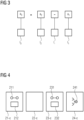
- Figure 4 schematically shows a plurality of four modular entities 21-c, 22-c, 23-c, 24-c of a flexible modular plant prior to arrangement of the modular entities 21-c, 22-c, 23-c, 24-c.
- the first modular entity 21-c comprises a first sensor 211 and a first certificate 212
- the third modular entity 21-c comprises a second sensor 231 and a second certificate 232.
- the fourth modular entity 24-c comprises means 241 for computing the difference of the value provided by the second sensor 231 and the first sensor 211.
- Figure 5 schematically shows the four modular entities 21-c, 22-c, 23-c, 24-c of figure 4 after arrangement of the modular entities 21-c, 22-c, 23-c, 24-c.
- the first sensor 211 is connected via the second modular entity 22-c and the third modular entity 23-c to an input of the means 241 of the fourth modular entity 24-c.
- the second sensor 232 is connected to an input of the means 241 of the fourth modular entity 24-c.
- Figure 6 schematically shows a calculation tree T for calculating an output value.
- the computing unit 12 may provide such a calculation tree T corresponding to the way how the output value is calculated based on the input values.
- five external nodes n1 to n5 may correspond to five input values provided by modular entities.
- the calculation tree further comprises three internal nodes n6, n7, n8 responding to intermediate steps in calculating the output value.
- a value associated with a first internal node n6 is calculated based on values associated with the first and second input values n1 and n2.
- the values of the second and third internal nodes n7, n8 are based on a calculation based on values associated with the first internal node n6 and the third external node n3 or the fourth and the fifth external node n4, n5, respectively.
- a root node n9 of the calculation tree T corresponds to an output value calculated based on the values of the second and third internal nodes n7, n8.
- the calculations may for instance comprise an addition, a subtraction or other mathematical operations applied to the values of the respective nodes.
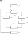
- Figure 7 schematically shows a flow diagram of a method for providing output values with associated uncertainties for a flexible modular plant according to an embodiment of the invention.
- the modular plant comprises an arrangement of a first plurality of modular entities.
- a first step S1 to each modular entity of a second plurality of modular entities, uncertainty information is provided associated with an operation of the respective modular entity.
- the second plurality of modular entities may be identical to or maybe a subset of the first plurality of modular entities.
- the uncertainty information may be added to a digital twin of the respective modular entity.
- a second step S2 at least some of the modular entities of the second plurality of modular entities provides input values to a device 1 for providing output values, as described above.
- the input values may comprise measurement data provided by said modular entities.
- a computing unit 12 of said device 1 calculates an output value based on the input values provided by the modular entities.
- the computing unit 12 may further provide a calculation tree T associated with the calculation of the output value based on the input values. For different ways to calculate the output value, different calculation trees T may be provided.
- the computing unit 12 further computes an input value uncertainty for each input value based on the uncertainty information of the modular entity providing the input value.
- a fifth step S5 the computing unit calculates at least one output value uncertainty associated with the output value based on propagation of uncertainty and using the input value uncertainties.
- the step S3 may be performed in parallel with steps S4 and S5.
- the step S3 may also be carried out before or after steps S4 and S5.
- a trust value and/or a time stamp may be assigned to the output value.
- the trust value can be determined based on the time stamp of the output value.
- the output value uncertainty may be computed using code injection or overloading.
- the output value and the at least one output value uncertainty are provided as output to a user, e.g. on a display.
- the computing unit 12 may provide a list of the modular entities being ordered according to the contributions of the modular entities to the output value uncertainty. For computing the list, the computing unit 12 goes through the calculation tree T to track the contributions to the output value uncertainty.
- An engineering recommendation may be provided by the computing unit 12 to the user via the user interface 112 based on the ordered list. For example, the user may be advised to replace or update modular entities having a high contribution to the output value uncertainty.
- the optimal calculation tree may be determined by the computing unit 12, resulting in the lowest output value uncertainty. The calculation tree may be presented to the user as an optimal way to calculate the output value.
- step S7 the modular entities may be rearranged.
- the method starts over from step S2, i.e. the output value and at least one output value uncertainty are updated.
- the modular entities may be rearranged if the arrangement of the modular entities fails to comply with predetermined uncertainty requirements based on an assessment of the computing unit 12 using the at least one output value uncertainty.
Landscapes
- Engineering & Computer Science (AREA)
- Physics & Mathematics (AREA)
- General Physics & Mathematics (AREA)
- Automation & Control Theory (AREA)
- Manufacturing & Machinery (AREA)
- General Engineering & Computer Science (AREA)
- Quality & Reliability (AREA)
- Business, Economics & Management (AREA)
- General Health & Medical Sciences (AREA)
- Economics (AREA)
- Health & Medical Sciences (AREA)
- Human Resources & Organizations (AREA)
- Marketing (AREA)
- Primary Health Care (AREA)
- Strategic Management (AREA)
- Tourism & Hospitality (AREA)
- General Business, Economics & Management (AREA)
- Theoretical Computer Science (AREA)
- Testing And Monitoring For Control Systems (AREA)
- Testing Or Calibration Of Command Recording Devices (AREA)
Description
- The invention relates to a method and a device for providing output values with associated uncertainties for a flexible modular plant or machine.
- Manufacturing plants based on modular entities is beneficial with regard to an increased flexibility in plant arrangement, a reduction of safety concerns during construction of the modular plant and with regard to easier modification and replacement of modular entities.
- The modular entities or equipment of such flexible modular plants may comprise components such as electrical wiring, walls, pipes, machines, actuators and sensors. The modular entities are installed according to a certain arrangement which describes the way in which the modular entities are connected to each other.
- Sensors can measure physical and chemical properties and provide measurement data which is afflicted with measurement uncertainties. The degree and type of uncertainty can be specified in the documentation of the respective sensor and may be certified by appropriate authorities.
- The publication
EP0862 683 A1 - Hartmann "METHOD OF QUALIFYING A BOREHOLE SURVEY" discloses the evaluation of an uncertainty in quality inspection of a borehole. In this method several uncertainties, e.g., in measuring of earth field parameters, are considered. - If the measurement data is transformed or combined with other data, e.g. in the way of sensor fusion, propagation of uncertainty or error propagation becomes relevant. Definitions, formal representations and propagation of measurement uncertainties are standardized and given in norms such as DIN 1319 or IEEE-754. Additional uncertainties may occur through the limited representation of numbers in digital processes, e.g. by using floating-point representations.
- For flexible modular plants, the setup of the plant and the available measurement equipment is not known at the design stage. During runtime, it is decided which process is to be executed on which equipment or entity by a system implementing methods like Supervisory Control and Data Acquisition (SCADA), Manufacturing Operation Management (MOM) and Manufacturing Execution System (MES).
- Therefore, if input values from a plurality of modular entities are combined to provide an output value, it is not possible to calculate the measurement uncertainties during design time.
- It is therefore an object of the present invention to provide a method and a device which allow deriving uncertainties of output values during runtime.
- This object is solved by the subject matter of the independent claims. Advantageous embodiments are set out in the dependent claims.
- Therefore, the invention provides a method for providing output values with associated uncertainties for a flexible modular plant or machine comprising an arrangement of modular entities. To a plurality of modular entities, uncertainty information is assigned, associated with the operation of the respective modular entity. The plurality of modular entities provides input values, wherein each input value is based on an operation of the respective modular entity of the plurality of modular entities. A computing unit calculates an output value based on the input values provided by the plurality of modular entities. The computing unit calculates an input value uncertainty for each input value based on the uncertainty information of the modular entity which has provided the input value. Further, the computing unit calculates at least one output value uncertainty or confidence associated with the output value based on propagation of uncertainty and using the input value uncertainties. The output value and the at least one output value uncertainty are provided as output.
- The invention further provides a device for providing output values with associated uncertainties for a flexible modular plant or machine. The flexible modular plant or machine comprises an arrangement of modular entities. To each modular entity of a plurality of said modular entities, uncertainty information is assigned associated with an operation of the respective modular entity. The device comprises an interface and a computing unit. The interface is adapted to receive, by the plurality of modular entities, input values based on an operation of the plurality of modular entities. The computing unit calculates an output value based on the input values provided by the plurality of modular entities. The computing unit further calculates an input value uncertainty for each input value based on the uncertainty information of the modular entity that has provided the input value. The computing unit is further adapted to calculate at least one output value uncertainty associated with the output value based on propagation of uncertainty using the input value uncertainties. The interface is adapted to output the output value and the at least one output value uncertainty.
- According to the invention, information about the uncertainties of the modular entities is available and provided in a formal way that allows for application in digital processes. Accordingly, the computing unit can provide an automatic calculation of the output value uncertainties by means of propagation of uncertainty. If the arrangement of modular entities changes, for instance by adding or removing modular entities or by arranging the modular entities in a different way, the updated uncertainty information of the modular entities according to the new arrangement is provided to the computing unit. The computing unit may therefore calculate updated output value uncertainties based on the new arrangement of the modular entities.
- Preferably, the computing unit calculates the output value and/or the output value uncertainty based on the arrangement of the modular entities. If the arrangement of modular entities changes, the output unit will automatically update the calculation of the output value and/or the output value uncertainty. Accordingly, during runtime, output values and output value uncertainties are automatically correctly calculated based on the respective configuration of the modular entities of the flexible modular plant or machine.
- According to a further embodiment of the method, at least one calculation tree is provided, describing how the output value is calculated based on the input values. Each node of the calculation tree corresponds to certain values, such as input and output values or values appearing at intermediate steps of the calculation. In addition, each node may comprise additional information, such as the uncertainty assigned to the respective value.
- According to an embodiment of the method, external nodes of the at least one calculation tree correspond to the input values provided by the plurality of modular entities. Internal nodes of the at least one calculation tree correspond to intermediate steps in calculating the output value. A root node of the at least one calculation tree corresponds to the output value.
- According to a further embodiment of the method, for each calculation tree, there is provided a list of the plurality of modular entities. The list is ordered according to the contributions of the modular entities to the output value uncertainty, based on the at least one calculation tree and based on the input value uncertainties. By inspecting the list, an engineer can easily identify modular entities having a huge influence on the output value uncertainties. Therefore, it becomes easier to modify the arrangement of the modular entities to reduce the uncertainties. For example, the information may be provided in form of a "heat map" which graphically shows which modular entities contribute more or less to the output value uncertainties.
- According to a further embodiment of the method, an engineering recommendation regarding the modular entities is provided based on the list of the modular entities. Engineering recommendation may be provided in form of a list of preferred options, such as rearranging certain modular entities.
- According to a further embodiment of the method, the engineering recommendation comprises a recommendation to replace at least one of the modular entities by at least one modular entity with a reduced uncertainty. For example, a sensor may be replaced by a more precise sensor, e.g. based on a different operation principle.
- According to a further embodiment of the method, if a plurality of different calculation trees is provided for calculating the output value, corresponding to different ways to calculate the output value, the optimal calculation tree is determined, resulting in the lowest output value uncertainty. The order in which different input values are processed in order to provide an output value can have significant effects on the at least one uncertainty value of the output value. Accordingly, different calculation trees may result in different uncertainty values. By choosing optimal calculation trees, the total error of the calculations can be minimized.
- According to a further embodiment of the method, at least one of a trust value and a time stamp is assigned to the output value. The trust value or confidence may be a value that can be changed manually or automatically to indicate how valid the output value is.
- According to a further embodiment of the method, the trust value of the output value is determined based on the time stamp of the output value. For example, the trust value may be reduced as the time passes since the actual measurement increases.
- According to a further embodiment of the method, the modular entities comprise sensors for measuring physical and/or chemical quantities. The sensors may comprise any active or passive equipment, e.g. thermal elements, light sensors, mechanical or electronic sensors.
- According to a further embodiment of the method, it is determined whether a configuration of the modular entities complies with uncertainty requirements using the at least one output value uncertainty. For instance, there may be provided a threshold for the uncertainty values. The configuration of the modular entities only complies with the uncertainty requirements if the at least one output value uncertainty is smaller than the respective threshold.
- According to a further embodiment of the method, the step of calculating the at least one output value uncertainty depends on the arrangement of the modular entities. The calculation of the at least one output value uncertainty is updated if the arrangement of the modular entities changes.
- According to a further embodiment of the method, the step of calculating the at least one output value uncertainty is performed using code injection or overloading. Code injection, in this context, means that for computation steps for the calculation of the output value, there are corresponding computation steps for the calculation of the at least one output value uncertainty associated with the output value. The corresponding computation steps may be performed in parallel. According to other embodiments, the calculation step for the calculation of the at least one output value uncertainty is performed immediately before or immediately after the respective calculation step for the calculation of the output value. Overloading may be used in the context of object-oriented programming to calculate both the output value and the respective output value uncertainty.
- According to a further embodiment of the method, for each modular entity, the corresponding uncertainty information associated with the operation of the modular entity is assigned to a digital twin of the modular entity.
- The invention also provides a computer program comprising executable program code configured to, when executed (e.g. by a computing device), perform the method according to the invention.
- The invention also provides a non-transitory computer-readable data storage medium comprising executable program code configured to, when executed (e.g. by a computing device), perform the method according to the invention.
- The invention will be explained in greater detail with reference to exemplary embodiments depicted in the drawings as appended.
- The accompanying drawings are included to provide a further understanding of the present invention and are incorporated in and constitute a part of this specification. The drawings illustrate embodiments of the present invention and together with the description serve to explain the principles of the invention.
- Other embodiments of the present invention and many of the intended advantages of the present invention will be readily appreciated as they become better understood by reference to the following detailed description. Like reference numerals designate corresponding similar parts. It should be understood that method steps are numbered for easier reference but that said numbering does not necessarily imply steps being performed in that order unless explicitly or implicitly described otherwise. In particular, steps may also be performed in a different order than indicated by their numbering. Some steps may be performed simultaneously or in an overlapping manner.
- Fig. 1
- schematically shows a block diagram illustrating a device for providing output values with associated uncertainties for a flexible modular plant according to an embodiment of the invention;
- Fig. 2
- schematically shows three consecutively arranged modular entities of a flexible modular plant;
- Fig. 3
- schematically shows an exemplary calculation of an output value based on input values;
- Fig. 4
- schematically shows a plurality of modular entities of a flexible modular plant prior to arrangement of the modular entities;
- Fig. 5
- schematically shows a plurality of modular entities of a flexible modular plant after arrangement of the modular entities;
- Fig. 6
- schematically shows a calculation tree for calculating an output value; and
- Fig. 7
- schematically shows a flow diagram of a method for providing output values with associated uncertainties for a flexible modular plant according to an embodiment of the invention.
-
Figure 1 shows a block diagram illustrating adevice 1 for providing output values with associated uncertainties for a flexible modular plant. Whereas the invention will in the following be described with respect to a flexible modular plant, it is also applicable to a flexible modular machine. Thedevice 1 comprises aninterface 11 which is connected to a plurality of modular entities 21-a to 2n-a, wherein n is an integer value greater than one. The modular entities 21-a to 2n-a are physical equipment that can be combined during runtime. The modular entities 21-a to 2n-a may comprise electrical wiring, walls, pipes, machines, actuators and sensors. The modular entities 21-a to 2n-a are installed according to a certain arrangement which describes the way in which the modular entities are connected to each other. The arrangement may change during runtime. E.g., during runtime, new modular entities 21-a to 2n-a may be added or may be connected to already existing modular entities 21-a to 2n-a, already existing modular entities 21-a to 2n-a may be disconnected from the arrangement or may be replaced by possibly different modular entities 21-a to 2n-a. - The engineering and planning of the flexible modular plant may be based on digital twins assigned to the modular entities 21-a to 2n-a. Further, uncertainty information is associated with an operation of the modular entities 21-a to 2n-a. The digital twins may comprise the uncertainty information. The uncertainty information may be associated with each modular entity 21-a to 2n-a of the modular entities 21-a to 2n-a. Uncertainty information can also be associated with a subset of the modular entities 21-a to 2n-a, e.g. with all or a subset of the sensors and/or actuators. The uncertainty information may be provided in the form of a lookup table specifying the uncertainty associated with a certain input value provided by the corresponding modular entity 21-a to 2n-a. If the uncertainty is equal to a certain percentage, irrespective of the specific input value provided by the modular entity 21-a to 2n-a, the uncertainty information may consist of said percentage.
- At least some of the modular entities 21-a to 2n-a provide input data to the
device 1 via aninput unit 111 of theinterface 11. Theinput unit 111 may be any kind of port or link or interface capable of receiving information from the modular entities 21-a to 2n-a, e.g. WLAN, Bluetooth, ZigBee, Profibus, ETHERNET etc. - The input data provided by the modular entities 21-a to 2n-a based on an operation of the modular entities 21-a to 2n-a may comprise measurement data generated based on the measurement of the modular entities 21-a to 2n-a related to the environment of the respective modular entity 21-a to 2n-a or related to the modular entity 21-a to 2n-a itself. For example, the input data may comprise measurement of a temperature, a weight, a pressure, and the like. Input data may also comprise information regarding the modular entities 21-a to 2n-a, e.g. consumption or runtime of the modular entity 21-a to 2n-a.
- The input data is further processed by a
computing unit 12 of thedevice 1. Thecomputing unit 12 can comprise at least one of a central processing unit (CPU) or graphics processing unit (GPU) like a microcontroller (pC), an integrated circuit (IC), an application-specific integrated circuit (ASIC), an application-specific standard product (ASSP), a digital signal processor (DSP), a field programmable gate array (FPGA) and the like. Thecomputing unit 12 may further comprise a memory or medium for storing data processed during operation, e.g. the received input data. - The
computing unit 12 calculates an output value based on the input values provided by the plurality of modular entities 21-a to 2n-a. The output value can for example be a physical or chemical quantity related to an end product made in the flexible modular plant. E.g., the output value may comprise a weight of the end product. The output value can be computed based on several input values, e.g. corresponding to weights of intermediate products. The way the input values are taken into account for calculating the output value depends on the configuration or arrangement of the modular entities 21-a to 2n-a of the flexible modular plant. - The
computing unit 12 further calculates an input value uncertainty for each input value based on the uncertainty information of the modular entities 21-a to 2n-a. For example, the uncertainty information associated with a specific modular entity 21-a to 2n-a may specify that a measurement value provided by said modular entity 21-a to 2n-a has an uncertainty of 10 percent. Thecomputing unit 12 calculates the input value uncertainty for the input value provided by said modular entity 21-a to 2n-a to be 10 percent of said input value. Thecomputing unit 12 may compute the output value uncertainty using code injection or overloading. - The computing unit further computes at least one output value uncertainty associated with the output value. The output value uncertainty is computed based on propagation of uncertainty methods, i.e. error propagation. Sometimes, there may be several ways to compute the output value based on the input values provided by the modular entities 21-a to 2n-a. In this case, a separate output value uncertainty is calculated for each way to calculate the output value.
- The
computing unit 12 may further be adapted to determine whether the present arrangement of the modular entities 21-a to 2n-a complies with predetermined uncertainty requirements. For example, the at least one output value uncertainty can be compared with a predetermined threshold. If the at least one output value uncertainty exceeds the predetermined threshold, the present arrangement fails to comply with the uncertainty requirements. Thecomputing unit 12 may provide a warning signal. - The
interface 11 of thedevice 1 further comprises auser interface 112 for providing information to a user of thedevice 1. Theuser interface 112 may comprise a display, printer, speaker, and the like. The output value and the at least one output value uncertainty are provided to the user via theuser interface 112. Further, if thecomputing unit 12 is provided a warning signal, the warning signal may be presented to the user via theuser interface 112. - The
interface 11 of thedevice 1 further comprises anoutput unit 113 which may be identical to theinput unit 111 or may be a separate unit, such as a WLAN, Bluetooth, ZigBee, Profibus, ETHERNET interface, and the like. Theoutput unit 113 is connected to anexternal device 3, e.g. a processing unit further adapted to process the output value and the output value uncertainty. Theexternal device 3 may be adapted to automatically control at least some of the modular entities 21-a to 2n-a or to change configurations of the at least one modular entities 21-a to 2n-a based on the output value and/or at least one output value uncertainty. -
Figure 2 schematically shows an arrangement of three consecutively arranged modular entities 21-b to 23-b of a flexible modular plant. A first modular entity 21-b comprises means for determining the weight of atray 4 on a conveyor belt and provides the weight as a first input value to thedevice 1. A second modular entity 22-b comprises means for inserting a certain product orsubstance 5 into thetray 4 on a further section of the conveyor belt. A third modular entity 23-b comprises means for measuring the weight of thetray 4 with the product orsubstance 5. Said weight is provided as a second input value to thedevice 1. Thecomputing unit 12 computes a weight of the product orsubstance 5 by subtracting the weight of thetray 4 based on the first input value from the weight of thetray 4 with the product orsubstance 5 based on the second input value. The computing unit 2 further calculates input value uncertainties of the first and second input value based on the uncertainty information associated with the first and third modular entities 21-b, 23-b. Thecomputing unit 12 further computes an output value uncertainty based on the input value uncertainties of the first and second input values. This calculation is further explained with reference tofigure 3 . -
Figure 3 schematically shows an exemplary calculation of an output value based on input values. A first information I_1 is associated with the first input value a_1 corresponding to the weight of thetray 4. The first information I_1 may comprise the value and the unit of the weight, e.g. 5.00 kg. The first information further comprises a lower uncertainty value and a higher uncertainty value, e.g. uncertainty _low = -0.05 and uncertainty_high = 0.05, calculated based on the uncertainty information associated with the first modular entity 21-b and on the input value provided by the first modular entity 21-b, i.e. the weight value. The first information I_1 may further comprise information regarding a uncertainty distribution, e.g. distribution = "equal" corresponding to an equal distribution. The first information I_1 may further comprise a trust value, e.g. trust = 98% and may comprise information regarding the derivation of the value, e.g. derivation → certificate!, that is the value is an original input not based on prior calculations. - A corresponding second information I_2 is associated with the second input value a_2 corresponding to the weight of the
tray 4 with the product orsubstance 5. The second information I_2 comprises the value and unit, e.g. 7.8 kg, the uncertainty, e.g. uncertainty_low = -0.10, uncertainty_high = 0.10, the distribution, e.g. "equal", the trust, e.g. 100 percent, and the derivation, e.g. derivation → certificate2. - Further, information I_- is associated with the calculation step of subtracting the first value a_1 from the second value a_2. The information I_- comprises the calculation prescription, e.g. value = value.a2 - value.a1, the unit, e.g. kg, and the lower and upper uncertainty values, e.g.:


- The information I_- further comprises a distribution, e.g. "equal", a trust, e.g. min(trust.a1,trust.a2) and information, e.g. derivation → derivation.g1, derivation.g2.
- Further, third information I_3 is associated with the output value a_3, comprising a value and a unit, e.g. 2.8 kg, uncertainty bounds, e.g. uncertainty _low = -0.15, uncertainty _high = 0.15, a distribution, e.g. "equal, a trust, e.g. 98 percent, and a derivation, e.g. ("-",a2,a1); a2 → certificate2, a1 → certificate1. The third information I_3 is generated based on the first information I_1, the second information I_2 and the information I_-. The
computing unit 12 may compute the uncertainty bounds, i.e. the output value uncertainty associated with the output value based on standard methods of propagation of uncertainty, for example as provided in norms such as DIN 1319. - The information I_1, I_2, I_3, I_- may be stored in a memory of the
computing unit 12. -
Figure 4 schematically shows a plurality of four modular entities 21-c, 22-c, 23-c, 24-c of a flexible modular plant prior to arrangement of the modular entities 21-c, 22-c, 23-c, 24-c. The first modular entity 21-c comprises afirst sensor 211 and afirst certificate 212, the third modular entity 21-c comprises asecond sensor 231 and asecond certificate 232. The fourth modular entity 24-c comprises means 241 for computing the difference of the value provided by thesecond sensor 231 and thefirst sensor 211. -
Figure 5 schematically shows the four modular entities 21-c, 22-c, 23-c, 24-c offigure 4 after arrangement of the modular entities 21-c, 22-c, 23-c, 24-c. Thefirst sensor 211 is connected via the second modular entity 22-c and the third modular entity 23-c to an input of themeans 241 of the fourth modular entity 24-c. Thesecond sensor 232 is connected to an input of themeans 241 of the fourth modular entity 24-c. -
Figure 6 schematically shows a calculation tree T for calculating an output value. Thecomputing unit 12 may provide such a calculation tree T corresponding to the way how the output value is calculated based on the input values. For example, five external nodes n1 to n5 may correspond to five input values provided by modular entities. The calculation tree further comprises three internal nodes n6, n7, n8 responding to intermediate steps in calculating the output value. For example, a value associated with a first internal node n6 is calculated based on values associated with the first and second input values n1 and n2. The values of the second and third internal nodes n7, n8 are based on a calculation based on values associated with the first internal node n6 and the third external node n3 or the fourth and the fifth external node n4, n5, respectively. A root node n9 of the calculation tree T corresponds to an output value calculated based on the values of the second and third internal nodes n7, n8. The calculations may for instance comprise an addition, a subtraction or other mathematical operations applied to the values of the respective nodes. -
Figure 7 schematically shows a flow diagram of a method for providing output values with associated uncertainties for a flexible modular plant according to an embodiment of the invention. The modular plant comprises an arrangement of a first plurality of modular entities. - In a first step S1, to each modular entity of a second plurality of modular entities, uncertainty information is provided associated with an operation of the respective modular entity. The second plurality of modular entities may be identical to or maybe a subset of the first plurality of modular entities. The uncertainty information may be added to a digital twin of the respective modular entity.
- In a second step S2, at least some of the modular entities of the second plurality of modular entities provides input values to a
device 1 for providing output values, as described above. The input values may comprise measurement data provided by said modular entities. - In a third step S3, a
computing unit 12 of saiddevice 1 calculates an output value based on the input values provided by the modular entities. Thecomputing unit 12 may further provide a calculation tree T associated with the calculation of the output value based on the input values. For different ways to calculate the output value, different calculation trees T may be provided. - In a fourth step S4, the
computing unit 12 further computes an input value uncertainty for each input value based on the uncertainty information of the modular entity providing the input value. - In a fifth step S5, the computing unit calculates at least one output value uncertainty associated with the output value based on propagation of uncertainty and using the input value uncertainties. The step S3 may be performed in parallel with steps S4 and S5. The step S3 may also be carried out before or after steps S4 and S5. Further, a trust value and/or a time stamp may be assigned to the output value. The trust value can be determined based on the time stamp of the output value. The output value uncertainty may be computed using code injection or overloading.
- In a sixth step S6, the output value and the at least one output value uncertainty are provided as output to a user, e.g. on a display. Further, the
computing unit 12 may provide a list of the modular entities being ordered according to the contributions of the modular entities to the output value uncertainty. For computing the list, thecomputing unit 12 goes through the calculation tree T to track the contributions to the output value uncertainty. An engineering recommendation may be provided by thecomputing unit 12 to the user via theuser interface 112 based on the ordered list. For example, the user may be advised to replace or update modular entities having a high contribution to the output value uncertainty. If there are several calculation trees T, corresponding to different ways to calculate the output value, the optimal calculation tree may be determined by thecomputing unit 12, resulting in the lowest output value uncertainty. The calculation tree may be presented to the user as an optimal way to calculate the output value. - In an additional step S7 the modular entities may be rearranged. The method starts over from step S2, i.e. the output value and at least one output value uncertainty are updated. The modular entities may be rearranged if the arrangement of the modular entities fails to comply with predetermined uncertainty requirements based on an assessment of the
computing unit 12 using the at least one output value uncertainty. - It should be understood that all advantageous options, variance in modifications described herein and the foregoing with respect to embodiments of the system according to the first aspect may be equally applied to embodiments of the method according to the second aspect, and vice versa.
- In the foregoing detailed description, various features are grouped together in one or more examples for the purpose of streamlining the disclosure. It is to be understood that the above description is intended to be illustrative, and not restrictive. It is intended to cover alternatives, modifications and equivalents. Many other examples will be apparent to one skilled in the art upon reviewing the above specification.
Claims (15)
- A method for providing output values with associated uncertainties for a flexible modular plant or machine comprising an arrangement of modular entities (21-2n), the method comprising the steps:during runtime of the flexible modular plant or machine, combining a plurality of said modular entities (21-2n) to an arrangement, the arrangement describing the way in which the modular entities (21-2n) are connected to each other,assigning, to the plurality of said modular entities (21-2n), uncertainty information associated with an operation of said modular entity (21-2n);providing, by said plurality of modular entities (21-2n), input values based on an operation of said modular entities (21-2n);depending on the arrangement of the plurality of said modular entities (21-2n), calculating, by a computing unit (12), an output value based on said input values provided by said plurality of modular entities (21-2n);calculating, by said computing unit (12), an input value uncertainty for each input value based on the uncertainty information of the modular entity (21-2n) providing the input value;depending on the arrangement of the plurality of said modular entities (21-2n), calculating, by said computing unit (12), at least one output value uncertainty associated with the output value based on propagation of uncertainty and using the input value uncertainties; and outputting said output value and said at least one output value uncertainty.
- The method according to claim 1, further comprising the step of providing at least one calculation tree (T) describing how said output value is calculated based on said input values.
- The method according to claim 2, wherein external nodes (n1-n5) of said at least one calculation tree (T) correspond to said input values provided by said plurality of modular entities (21-2n), wherein internal nodes (n6-n8) of said at least one calculation tree (T) correspond to intermediate steps in calculating the output value, and wherein a root node (n9) of said at least one calculation tree (T) corresponds to said output value.
- The method according to claims 2 or 3, further comprising, for each calculation tree (T), the step of providing a list of said plurality of modular entities (21-2n), wherein said list is ordered according to the contributions of the modular entities (21-2n) to the output value uncertainty, based on said at least one calculation tree (T) and said input value uncertainties.
- The method according to claim 4, further comprising the step of providing an engineering recommendation regarding said plurality of modular entities (21-2n) based on said list of said plurality of modular entities (21-2n).
- The method according to claim 5, wherein said engineering recommendation comprises a recommendation to replace at least one of said modular entities (21-2n) of said plurality of modular entities by at least one modular entity (21-2n) with a reduced uncertainty.
- The method according to any of claims 2 to 6, wherein, if a plurality of different calculation trees is provided for calculating the output value, corresponding to different ways to calculate said output value, an optimal calculation tree is determined, wherein the optimal calculation tree results in the lowest output value uncertainty.
- The method according to any of the preceding claims, further comprising the step of assigning at least one of a trust value and a time stamp to said output value.
- The method according to claim 8, wherein the trust value of said output value is determined based on the time stamp of said output value.
- The method according to any of the preceding claims, wherein the modular entities (21-2n) comprise sensors for measuring physical and/or chemical quantities.
- The method according to any of the preceding claims, further comprising the step of determining whether said arrangement of said modular entities (21-2n) complies with uncertainty requirements using said at least one output value uncertainty.
- The method according to any of the preceding claims, wherein the step of calculating said at least one output value uncertainty depends on said arrangement of said modular entities (21-2n), and wherein said calculation of said at least one output value uncertainty is updated if said arrangement of said modular entities (21-2n) changes.
- The method according to any of the preceding claims, wherein the step of calculating said at least one output value uncertainty is performed using code injection or overloading.
- The method according to any of the preceding claims, wherein, for each modular entity (21-2n) of said plurality of modular entities (21-2n), the corresponding uncertainty information associated with the operation of said modular entity (21-2n) is assigned to a digital twin of said modular entity (21-2n).
- A device (1) for providing output values with associated uncertainties for a flexible modular plant or machine, wherein the modular plant or machine comprises an arrangement of a combination of modular entities (21-2n),wherein the combination of the modular entities (21-2n) is subject to be made or changed during runtime of the flexible modular plant or machine,wherein to a plurality of said modular entities there is assigned uncertainty information associated with an operation of said modular entity (21-2n), the device (1) comprising:an interface (11) adapted to receive, by said plurality of modular entities (21-2n), input values based on an operation of said modular entities (21-2n); anda computing unit (12), adapted to calculate an output value based on said input values provided by said plurality of modular entities (21-2n), to calculate an input value uncertainty for each input value based on the uncertainty information of the modular entity (21-2n) providing the input value, and, during runtime, to calculate at least one output value uncertainty associated with the output value based on propagation of uncertainty using the input value uncertainties;wherein said interface (11) is adapted to output said output value and said at least one output value uncertainty.
Applications Claiming Priority (2)
| Application Number | Priority Date | Filing Date | Title |
|---|---|---|---|
| EP19191375.5A EP3779620A1 (en) | 2019-08-13 | 2019-08-13 | Automatic calculation of measurement confidence in flexi-ble modular plants and machines |
| PCT/EP2020/069694 WO2021028134A1 (en) | 2019-08-13 | 2020-07-13 | Automatic calculation of measurement confidence in flexible modular plants and machines |
Publications (2)
| Publication Number | Publication Date |
|---|---|
| EP3983855A1 EP3983855A1 (en) | 2022-04-20 |
| EP3983855B1 true EP3983855B1 (en) | 2023-06-21 |
Family
ID=67658691
Family Applications (2)
| Application Number | Title | Priority Date | Filing Date |
|---|---|---|---|
| EP19191375.5A Withdrawn EP3779620A1 (en) | 2019-08-13 | 2019-08-13 | Automatic calculation of measurement confidence in flexi-ble modular plants and machines |
| EP20746891.9A Active EP3983855B1 (en) | 2019-08-13 | 2020-07-13 | Automatic calculation of measurement confidence in flexible modular plants and machines |
Family Applications Before (1)
| Application Number | Title | Priority Date | Filing Date |
|---|---|---|---|
| EP19191375.5A Withdrawn EP3779620A1 (en) | 2019-08-13 | 2019-08-13 | Automatic calculation of measurement confidence in flexi-ble modular plants and machines |
Country Status (4)
| Country | Link |
|---|---|
| US (1) | US11609555B2 (en) |
| EP (2) | EP3779620A1 (en) |
| CN (1) | CN114222957B (en) |
| WO (1) | WO2021028134A1 (en) |
Citations (1)
| Publication number | Priority date | Publication date | Assignee | Title |
|---|---|---|---|---|
| EP0862683B1 (en) * | 1995-11-21 | 2000-02-02 | Shell Internationale Researchmaatschappij B.V. | Method of qualifying a borehole survey |
Family Cites Families (10)
| Publication number | Priority date | Publication date | Assignee | Title |
|---|---|---|---|---|
| NZ512212A (en) | 2001-06-06 | 2004-04-30 | Ind Res Ltd | Uncertainty calculation system and method |
| WO2002099361A1 (en) * | 2001-06-06 | 2002-12-12 | Industrial Research Limited | Uncertainty propagation system and method |
| JP4817251B2 (en) | 2006-09-22 | 2011-11-16 | シスメックス株式会社 | Quality control system |
| US7539593B2 (en) * | 2007-04-27 | 2009-05-26 | Invensys Systems, Inc. | Self-validated measurement systems |
| US8560468B1 (en) | 2011-02-10 | 2013-10-15 | Google Inc. | Learning expected values for facts |
| US8977373B2 (en) * | 2011-12-28 | 2015-03-10 | Caterpillar Inc. | Systems and methods for extending physical sensor range using virtual sensors |
| WO2013117236A1 (en) | 2012-02-10 | 2013-08-15 | Abb Technology Ag | System and method for automated handling of a workflow in an automation and/or electrical engineering project |
| WO2016040082A1 (en) * | 2014-09-10 | 2016-03-17 | Siemens Aktiengesellschaft | Gas turbine sensor failure detection utilizing a sparse coding methodology |
| DE102016101237B4 (en) * | 2016-01-25 | 2025-08-14 | Endress+Hauser SE+Co. KG | Arrangement on a container and/or a pipeline comprising at least one field device of automation technology |
| CN106991252A (en) | 2017-04-27 | 2017-07-28 | 上海理工大学 | Sophisticated testing Evaluation of Uncertainty method |
-
2019
- 2019-08-13 EP EP19191375.5A patent/EP3779620A1/en not_active Withdrawn
-
2020
- 2020-07-13 EP EP20746891.9A patent/EP3983855B1/en active Active
- 2020-07-13 CN CN202080056864.9A patent/CN114222957B/en active Active
- 2020-07-13 WO PCT/EP2020/069694 patent/WO2021028134A1/en not_active Ceased
- 2020-07-13 US US17/634,648 patent/US11609555B2/en active Active
Patent Citations (1)
| Publication number | Priority date | Publication date | Assignee | Title |
|---|---|---|---|---|
| EP0862683B1 (en) * | 1995-11-21 | 2000-02-02 | Shell Internationale Researchmaatschappij B.V. | Method of qualifying a borehole survey |
Also Published As
| Publication number | Publication date |
|---|---|
| WO2021028134A1 (en) | 2021-02-18 |
| US11609555B2 (en) | 2023-03-21 |
| CN114222957A (en) | 2022-03-22 |
| EP3779620A1 (en) | 2021-02-17 |
| EP3983855A1 (en) | 2022-04-20 |
| US20220269250A1 (en) | 2022-08-25 |
| CN114222957B (en) | 2022-12-06 |
Similar Documents
| Publication | Publication Date | Title |
|---|---|---|
| JP7320368B2 (en) | FAILURE PREDICTION DEVICE, FAILURE PREDICTION METHOD AND COMPUTER PROGRAM | |
| JP6496274B2 (en) | Machine learning device, failure prediction device, machine system and machine learning method for learning life failure condition | |
| JP6546213B2 (en) | Circuit configuration optimization device and machine learning device | |
| US20190251296A1 (en) | Method for tamper-proof evaluation of component properties of a field device | |
| CN108736881B (en) | Circuit configuration optimization device and machine learning device | |
| CN113532614A (en) | Method, processor and weighing system for predicting sensor data | |
| CN120180824A (en) | Blade high cycle fatigue analysis method and system considering the influence of crystal orientation angle | |
| US11609555B2 (en) | Device and method for automatic calculation of measurement confidence in flexible modular plants and machines | |
| EP2613474A1 (en) | Method and system for control system redundancy | |
| CN112236798A (en) | Method and computing device and computer program for quality assurance in the context of producing products | |
| US20090003230A1 (en) | Tool for communication system | |
| CN115129006B (en) | Process parameter adjustment method, related device, storage medium and program product | |
| CN114375389A (en) | Diagnostic system | |
| Tantik et al. | Industrie 4.0: Using cyber-physical systems for value-stream based production evaluation | |
| JP6457474B2 (en) | Manufacturing management apparatus and manufacturing system using inspection information and trace information | |
| CN118205885B (en) | Method, system, device and computer equipment for controlling position of mover in transmission system | |
| JP6244681B2 (en) | Compensation method for accumulated time series data loss | |
| Medjaher et al. | Diagnostic bond graphs for direct residual evaluation | |
| KR101622068B1 (en) | Setting calculation system learning device and learning method | |
| CN117092975A (en) | Production control method and system based on digital twin | |
| CN116305775A (en) | Nuclear power plant cable laying simulation method, device, computer equipment and storage medium | |
| Nadreri et al. | Statistically constrained economic design of X control chart with Weibull in-control time for processes subject to multiple assignable causes | |
| JP6605951B2 (en) | Simulation apparatus and simulation method | |
| EP3591592A1 (en) | Method and system for manufacturing industrial unit goods | |
| EP4331747A1 (en) | A method for generating a data package for producing a component by an additive manufacturing device, computer program product, computer-readable storage medium, electronic computing device as well as an additive manufacturing device |
Legal Events
| Date | Code | Title | Description |
|---|---|---|---|
| STAA | Information on the status of an ep patent application or granted ep patent |
Free format text: STATUS: UNKNOWN |
|
| STAA | Information on the status of an ep patent application or granted ep patent |
Free format text: STATUS: THE INTERNATIONAL PUBLICATION HAS BEEN MADE |
|
| PUAI | Public reference made under article 153(3) epc to a published international application that has entered the european phase |
Free format text: ORIGINAL CODE: 0009012 |
|
| STAA | Information on the status of an ep patent application or granted ep patent |
Free format text: STATUS: REQUEST FOR EXAMINATION WAS MADE |
|
| 17P | Request for examination filed |
Effective date: 20220114 |
|
| AK | Designated contracting states |
Kind code of ref document: A1 Designated state(s): AL AT BE BG CH CY CZ DE DK EE ES FI FR GB GR HR HU IE IS IT LI LT LU LV MC MK MT NL NO PL PT RO RS SE SI SK SM TR |
|
| DAV | Request for validation of the european patent (deleted) | ||
| DAX | Request for extension of the european patent (deleted) | ||
| GRAP | Despatch of communication of intention to grant a patent |
Free format text: ORIGINAL CODE: EPIDOSNIGR1 |
|
| STAA | Information on the status of an ep patent application or granted ep patent |
Free format text: STATUS: GRANT OF PATENT IS INTENDED |
|
| INTG | Intention to grant announced |
Effective date: 20230222 |
|
| GRAS | Grant fee paid |
Free format text: ORIGINAL CODE: EPIDOSNIGR3 |
|
| GRAA | (expected) grant |
Free format text: ORIGINAL CODE: 0009210 |
|
| STAA | Information on the status of an ep patent application or granted ep patent |
Free format text: STATUS: THE PATENT HAS BEEN GRANTED |
|
| AK | Designated contracting states |
Kind code of ref document: B1 Designated state(s): AL AT BE BG CH CY CZ DE DK EE ES FI FR GB GR HR HU IE IS IT LI LT LU LV MC MK MT NL NO PL PT RO RS SE SI SK SM TR |
|
| REG | Reference to a national code |
Ref country code: CH Ref legal event code: EP |
|
| REG | Reference to a national code |
Ref country code: DE Ref legal event code: R096 Ref document number: 602020012807 Country of ref document: DE |
|
| REG | Reference to a national code |
Ref country code: AT Ref legal event code: REF Ref document number: 1581340 Country of ref document: AT Kind code of ref document: T Effective date: 20230715 |
|
| REG | Reference to a national code |
Ref country code: IE Ref legal event code: FG4D |
|
| REG | Reference to a national code |
Ref country code: LT Ref legal event code: MG9D |
|
| REG | Reference to a national code |
Ref country code: NL Ref legal event code: MP Effective date: 20230621 |
|
| PG25 | Lapsed in a contracting state [announced via postgrant information from national office to epo] |
Ref country code: SE Free format text: LAPSE BECAUSE OF FAILURE TO SUBMIT A TRANSLATION OF THE DESCRIPTION OR TO PAY THE FEE WITHIN THE PRESCRIBED TIME-LIMIT Effective date: 20230621 Ref country code: NO Free format text: LAPSE BECAUSE OF FAILURE TO SUBMIT A TRANSLATION OF THE DESCRIPTION OR TO PAY THE FEE WITHIN THE PRESCRIBED TIME-LIMIT Effective date: 20230921 |
|
| REG | Reference to a national code |
Ref country code: AT Ref legal event code: MK05 Ref document number: 1581340 Country of ref document: AT Kind code of ref document: T Effective date: 20230621 |
|
| PG25 | Lapsed in a contracting state [announced via postgrant information from national office to epo] |
Ref country code: RS Free format text: LAPSE BECAUSE OF FAILURE TO SUBMIT A TRANSLATION OF THE DESCRIPTION OR TO PAY THE FEE WITHIN THE PRESCRIBED TIME-LIMIT Effective date: 20230621 Ref country code: NL Free format text: LAPSE BECAUSE OF FAILURE TO SUBMIT A TRANSLATION OF THE DESCRIPTION OR TO PAY THE FEE WITHIN THE PRESCRIBED TIME-LIMIT Effective date: 20230621 Ref country code: LV Free format text: LAPSE BECAUSE OF FAILURE TO SUBMIT A TRANSLATION OF THE DESCRIPTION OR TO PAY THE FEE WITHIN THE PRESCRIBED TIME-LIMIT Effective date: 20230621 Ref country code: LT Free format text: LAPSE BECAUSE OF FAILURE TO SUBMIT A TRANSLATION OF THE DESCRIPTION OR TO PAY THE FEE WITHIN THE PRESCRIBED TIME-LIMIT Effective date: 20230621 Ref country code: HR Free format text: LAPSE BECAUSE OF FAILURE TO SUBMIT A TRANSLATION OF THE DESCRIPTION OR TO PAY THE FEE WITHIN THE PRESCRIBED TIME-LIMIT Effective date: 20230621 Ref country code: GR Free format text: LAPSE BECAUSE OF FAILURE TO SUBMIT A TRANSLATION OF THE DESCRIPTION OR TO PAY THE FEE WITHIN THE PRESCRIBED TIME-LIMIT Effective date: 20230922 |
|
| PG25 | Lapsed in a contracting state [announced via postgrant information from national office to epo] |
Ref country code: FI Free format text: LAPSE BECAUSE OF FAILURE TO SUBMIT A TRANSLATION OF THE DESCRIPTION OR TO PAY THE FEE WITHIN THE PRESCRIBED TIME-LIMIT Effective date: 20230621 |
|
| PG25 | Lapsed in a contracting state [announced via postgrant information from national office to epo] |
Ref country code: SK Free format text: LAPSE BECAUSE OF FAILURE TO SUBMIT A TRANSLATION OF THE DESCRIPTION OR TO PAY THE FEE WITHIN THE PRESCRIBED TIME-LIMIT Effective date: 20230621 |
|
| PG25 | Lapsed in a contracting state [announced via postgrant information from national office to epo] |
Ref country code: ES Free format text: LAPSE BECAUSE OF FAILURE TO SUBMIT A TRANSLATION OF THE DESCRIPTION OR TO PAY THE FEE WITHIN THE PRESCRIBED TIME-LIMIT Effective date: 20230621 |
|
| PG25 | Lapsed in a contracting state [announced via postgrant information from national office to epo] |
Ref country code: IS Free format text: LAPSE BECAUSE OF FAILURE TO SUBMIT A TRANSLATION OF THE DESCRIPTION OR TO PAY THE FEE WITHIN THE PRESCRIBED TIME-LIMIT Effective date: 20231021 |
|
| PG25 | Lapsed in a contracting state [announced via postgrant information from national office to epo] |
Ref country code: SM Free format text: LAPSE BECAUSE OF FAILURE TO SUBMIT A TRANSLATION OF THE DESCRIPTION OR TO PAY THE FEE WITHIN THE PRESCRIBED TIME-LIMIT Effective date: 20230621 Ref country code: SK Free format text: LAPSE BECAUSE OF FAILURE TO SUBMIT A TRANSLATION OF THE DESCRIPTION OR TO PAY THE FEE WITHIN THE PRESCRIBED TIME-LIMIT Effective date: 20230621 Ref country code: RO Free format text: LAPSE BECAUSE OF FAILURE TO SUBMIT A TRANSLATION OF THE DESCRIPTION OR TO PAY THE FEE WITHIN THE PRESCRIBED TIME-LIMIT Effective date: 20230621 Ref country code: PT Free format text: LAPSE BECAUSE OF FAILURE TO SUBMIT A TRANSLATION OF THE DESCRIPTION OR TO PAY THE FEE WITHIN THE PRESCRIBED TIME-LIMIT Effective date: 20231023 Ref country code: IS Free format text: LAPSE BECAUSE OF FAILURE TO SUBMIT A TRANSLATION OF THE DESCRIPTION OR TO PAY THE FEE WITHIN THE PRESCRIBED TIME-LIMIT Effective date: 20231021 Ref country code: ES Free format text: LAPSE BECAUSE OF FAILURE TO SUBMIT A TRANSLATION OF THE DESCRIPTION OR TO PAY THE FEE WITHIN THE PRESCRIBED TIME-LIMIT Effective date: 20230621 Ref country code: EE Free format text: LAPSE BECAUSE OF FAILURE TO SUBMIT A TRANSLATION OF THE DESCRIPTION OR TO PAY THE FEE WITHIN THE PRESCRIBED TIME-LIMIT Effective date: 20230621 Ref country code: CZ Free format text: LAPSE BECAUSE OF FAILURE TO SUBMIT A TRANSLATION OF THE DESCRIPTION OR TO PAY THE FEE WITHIN THE PRESCRIBED TIME-LIMIT Effective date: 20230621 Ref country code: AT Free format text: LAPSE BECAUSE OF FAILURE TO SUBMIT A TRANSLATION OF THE DESCRIPTION OR TO PAY THE FEE WITHIN THE PRESCRIBED TIME-LIMIT Effective date: 20230621 |
|
| PG25 | Lapsed in a contracting state [announced via postgrant information from national office to epo] |
Ref country code: PL Free format text: LAPSE BECAUSE OF FAILURE TO SUBMIT A TRANSLATION OF THE DESCRIPTION OR TO PAY THE FEE WITHIN THE PRESCRIBED TIME-LIMIT Effective date: 20230621 |
|
| REG | Reference to a national code |
Ref country code: CH Ref legal event code: PL |
|
| PG25 | Lapsed in a contracting state [announced via postgrant information from national office to epo] |
Ref country code: MC Free format text: LAPSE BECAUSE OF FAILURE TO SUBMIT A TRANSLATION OF THE DESCRIPTION OR TO PAY THE FEE WITHIN THE PRESCRIBED TIME-LIMIT Effective date: 20230621 |
|
| REG | Reference to a national code |
Ref country code: BE Ref legal event code: MM Effective date: 20230731 |
|
| PG25 | Lapsed in a contracting state [announced via postgrant information from national office to epo] |
Ref country code: LU Free format text: LAPSE BECAUSE OF NON-PAYMENT OF DUE FEES Effective date: 20230713 |
|
| REG | Reference to a national code |
Ref country code: DE Ref legal event code: R097 Ref document number: 602020012807 Country of ref document: DE |
|
| PG25 | Lapsed in a contracting state [announced via postgrant information from national office to epo] |
Ref country code: MC Free format text: LAPSE BECAUSE OF FAILURE TO SUBMIT A TRANSLATION OF THE DESCRIPTION OR TO PAY THE FEE WITHIN THE PRESCRIBED TIME-LIMIT Effective date: 20230621 Ref country code: LU Free format text: LAPSE BECAUSE OF NON-PAYMENT OF DUE FEES Effective date: 20230713 |
|
| REG | Reference to a national code |
Ref country code: IE Ref legal event code: MM4A |
|
| PLBE | No opposition filed within time limit |
Free format text: ORIGINAL CODE: 0009261 |
|
| STAA | Information on the status of an ep patent application or granted ep patent |
Free format text: STATUS: NO OPPOSITION FILED WITHIN TIME LIMIT |
|
| PG25 | Lapsed in a contracting state [announced via postgrant information from national office to epo] |
Ref country code: DK Free format text: LAPSE BECAUSE OF FAILURE TO SUBMIT A TRANSLATION OF THE DESCRIPTION OR TO PAY THE FEE WITHIN THE PRESCRIBED TIME-LIMIT Effective date: 20230621 Ref country code: CH Free format text: LAPSE BECAUSE OF NON-PAYMENT OF DUE FEES Effective date: 20230731 |
|
| PG25 | Lapsed in a contracting state [announced via postgrant information from national office to epo] |
Ref country code: SI Free format text: LAPSE BECAUSE OF FAILURE TO SUBMIT A TRANSLATION OF THE DESCRIPTION OR TO PAY THE FEE WITHIN THE PRESCRIBED TIME-LIMIT Effective date: 20230621 |
|
| 26N | No opposition filed |
Effective date: 20240322 |
|
| PG25 | Lapsed in a contracting state [announced via postgrant information from national office to epo] |
Ref country code: SI Free format text: LAPSE BECAUSE OF FAILURE TO SUBMIT A TRANSLATION OF THE DESCRIPTION OR TO PAY THE FEE WITHIN THE PRESCRIBED TIME-LIMIT Effective date: 20230621 Ref country code: BE Free format text: LAPSE BECAUSE OF NON-PAYMENT OF DUE FEES Effective date: 20230731 |
|
| PG25 | Lapsed in a contracting state [announced via postgrant information from national office to epo] |
Ref country code: IE Free format text: LAPSE BECAUSE OF NON-PAYMENT OF DUE FEES Effective date: 20230713 |
|
| PG25 | Lapsed in a contracting state [announced via postgrant information from national office to epo] |
Ref country code: IE Free format text: LAPSE BECAUSE OF NON-PAYMENT OF DUE FEES Effective date: 20230713 |
|
| PG25 | Lapsed in a contracting state [announced via postgrant information from national office to epo] |
Ref country code: BG Free format text: LAPSE BECAUSE OF FAILURE TO SUBMIT A TRANSLATION OF THE DESCRIPTION OR TO PAY THE FEE WITHIN THE PRESCRIBED TIME-LIMIT Effective date: 20230621 |
|
| PG25 | Lapsed in a contracting state [announced via postgrant information from national office to epo] |
Ref country code: BG Free format text: LAPSE BECAUSE OF FAILURE TO SUBMIT A TRANSLATION OF THE DESCRIPTION OR TO PAY THE FEE WITHIN THE PRESCRIBED TIME-LIMIT Effective date: 20230621 |
|
| GBPC | Gb: european patent ceased through non-payment of renewal fee |
Effective date: 20240713 |
|
| PG25 | Lapsed in a contracting state [announced via postgrant information from national office to epo] |
Ref country code: GB Free format text: LAPSE BECAUSE OF NON-PAYMENT OF DUE FEES Effective date: 20240713 |
|
| PGFP | Annual fee paid to national office [announced via postgrant information from national office to epo] |
Ref country code: IT Payment date: 20231009 Year of fee payment: 6 |
|
| PG25 | Lapsed in a contracting state [announced via postgrant information from national office to epo] |
Ref country code: CY Free format text: LAPSE BECAUSE OF FAILURE TO SUBMIT A TRANSLATION OF THE DESCRIPTION OR TO PAY THE FEE WITHIN THE PRESCRIBED TIME-LIMIT; INVALID AB INITIO Effective date: 20200713 |
|
| PG25 | Lapsed in a contracting state [announced via postgrant information from national office to epo] |
Ref country code: HU Free format text: LAPSE BECAUSE OF FAILURE TO SUBMIT A TRANSLATION OF THE DESCRIPTION OR TO PAY THE FEE WITHIN THE PRESCRIBED TIME-LIMIT; INVALID AB INITIO Effective date: 20200713 |
|
| PGFP | Annual fee paid to national office [announced via postgrant information from national office to epo] |
Ref country code: DE Payment date: 20250919 Year of fee payment: 6 |
|
| PGFP | Annual fee paid to national office [announced via postgrant information from national office to epo] |
Ref country code: FR Payment date: 20250716 Year of fee payment: 6 |
|
| PG25 | Lapsed in a contracting state [announced via postgrant information from national office to epo] |
Ref country code: TR Free format text: LAPSE BECAUSE OF FAILURE TO SUBMIT A TRANSLATION OF THE DESCRIPTION OR TO PAY THE FEE WITHIN THE PRESCRIBED TIME-LIMIT Effective date: 20230621 |