EP3983703B1 - Seal for combustion apparatus - Google Patents
Seal for combustion apparatus Download PDFInfo
- Publication number
- EP3983703B1 EP3983703B1 EP20763988.1A EP20763988A EP3983703B1 EP 3983703 B1 EP3983703 B1 EP 3983703B1 EP 20763988 A EP20763988 A EP 20763988A EP 3983703 B1 EP3983703 B1 EP 3983703B1
- Authority
- EP
- European Patent Office
- Prior art keywords
- seal
- metal web
- width
- gap
- strap
- Prior art date
- Legal status (The legal status is an assumption and is not a legal conclusion. Google has not performed a legal analysis and makes no representation as to the accuracy of the status listed.)
- Active
Links
Images


Classifications
-
- F—MECHANICAL ENGINEERING; LIGHTING; HEATING; WEAPONS; BLASTING
- F01—MACHINES OR ENGINES IN GENERAL; ENGINE PLANTS IN GENERAL; STEAM ENGINES
- F01D—NON-POSITIVE DISPLACEMENT MACHINES OR ENGINES, e.g. STEAM TURBINES
- F01D11/00—Preventing or minimising internal leakage of working-fluid, e.g. between stages
- F01D11/003—Preventing or minimising internal leakage of working-fluid, e.g. between stages by packing rings; Mechanical seals
-
- F—MECHANICAL ENGINEERING; LIGHTING; HEATING; WEAPONS; BLASTING
- F16—ENGINEERING ELEMENTS AND UNITS; GENERAL MEASURES FOR PRODUCING AND MAINTAINING EFFECTIVE FUNCTIONING OF MACHINES OR INSTALLATIONS; THERMAL INSULATION IN GENERAL
- F16J—PISTONS; CYLINDERS; SEALINGS
- F16J15/00—Sealings
- F16J15/02—Sealings between relatively-stationary surfaces
- F16J15/06—Sealings between relatively-stationary surfaces with solid packing compressed between sealing surfaces
- F16J15/08—Sealings between relatively-stationary surfaces with solid packing compressed between sealing surfaces with exclusively metal packing
- F16J15/0887—Sealings between relatively-stationary surfaces with solid packing compressed between sealing surfaces with exclusively metal packing the sealing effect being obtained by elastic deformation of the packing
-
- F—MECHANICAL ENGINEERING; LIGHTING; HEATING; WEAPONS; BLASTING
- F01—MACHINES OR ENGINES IN GENERAL; ENGINE PLANTS IN GENERAL; STEAM ENGINES
- F01D—NON-POSITIVE DISPLACEMENT MACHINES OR ENGINES, e.g. STEAM TURBINES
- F01D11/00—Preventing or minimising internal leakage of working-fluid, e.g. between stages
- F01D11/005—Sealing means between non relatively rotating elements
-
- F—MECHANICAL ENGINEERING; LIGHTING; HEATING; WEAPONS; BLASTING
- F01—MACHINES OR ENGINES IN GENERAL; ENGINE PLANTS IN GENERAL; STEAM ENGINES
- F01D—NON-POSITIVE DISPLACEMENT MACHINES OR ENGINES, e.g. STEAM TURBINES
- F01D9/00—Stators
- F01D9/02—Nozzles; Nozzle boxes; Stator blades; Guide conduits, e.g. individual nozzles
-
- F—MECHANICAL ENGINEERING; LIGHTING; HEATING; WEAPONS; BLASTING
- F01—MACHINES OR ENGINES IN GENERAL; ENGINE PLANTS IN GENERAL; STEAM ENGINES
- F01D—NON-POSITIVE DISPLACEMENT MACHINES OR ENGINES, e.g. STEAM TURBINES
- F01D9/00—Stators
- F01D9/02—Nozzles; Nozzle boxes; Stator blades; Guide conduits, e.g. individual nozzles
- F01D9/023—Transition ducts between combustor cans and first stage of the turbine in gas-turbine engines; their cooling or sealings
-
- F—MECHANICAL ENGINEERING; LIGHTING; HEATING; WEAPONS; BLASTING
- F05—INDEXING SCHEMES RELATING TO ENGINES OR PUMPS IN VARIOUS SUBCLASSES OF CLASSES F01-F04
- F05D—INDEXING SCHEME FOR ASPECTS RELATING TO NON-POSITIVE-DISPLACEMENT MACHINES OR ENGINES, GAS-TURBINES OR JET-PROPULSION PLANTS
- F05D2220/00—Application
- F05D2220/30—Application in turbines
- F05D2220/32—Application in turbines in gas turbines
-
- F—MECHANICAL ENGINEERING; LIGHTING; HEATING; WEAPONS; BLASTING
- F05—INDEXING SCHEMES RELATING TO ENGINES OR PUMPS IN VARIOUS SUBCLASSES OF CLASSES F01-F04
- F05D—INDEXING SCHEME FOR ASPECTS RELATING TO NON-POSITIVE-DISPLACEMENT MACHINES OR ENGINES, GAS-TURBINES OR JET-PROPULSION PLANTS
- F05D2240/00—Components
- F05D2240/10—Stators
- F05D2240/12—Fluid guiding means, e.g. vanes
-
- F—MECHANICAL ENGINEERING; LIGHTING; HEATING; WEAPONS; BLASTING
- F05—INDEXING SCHEMES RELATING TO ENGINES OR PUMPS IN VARIOUS SUBCLASSES OF CLASSES F01-F04
- F05D—INDEXING SCHEME FOR ASPECTS RELATING TO NON-POSITIVE-DISPLACEMENT MACHINES OR ENGINES, GAS-TURBINES OR JET-PROPULSION PLANTS
- F05D2240/00—Components
- F05D2240/35—Combustors or associated equipment
-
- F—MECHANICAL ENGINEERING; LIGHTING; HEATING; WEAPONS; BLASTING
- F05—INDEXING SCHEMES RELATING TO ENGINES OR PUMPS IN VARIOUS SUBCLASSES OF CLASSES F01-F04
- F05D—INDEXING SCHEME FOR ASPECTS RELATING TO NON-POSITIVE-DISPLACEMENT MACHINES OR ENGINES, GAS-TURBINES OR JET-PROPULSION PLANTS
- F05D2240/00—Components
- F05D2240/55—Seals
-
- F—MECHANICAL ENGINEERING; LIGHTING; HEATING; WEAPONS; BLASTING
- F05—INDEXING SCHEMES RELATING TO ENGINES OR PUMPS IN VARIOUS SUBCLASSES OF CLASSES F01-F04
- F05D—INDEXING SCHEME FOR ASPECTS RELATING TO NON-POSITIVE-DISPLACEMENT MACHINES OR ENGINES, GAS-TURBINES OR JET-PROPULSION PLANTS
- F05D2250/00—Geometry
- F05D2250/70—Shape
- F05D2250/71—Shape curved
- F05D2250/711—Shape curved convex
Definitions
- the invention relates to a seal for sealing a gap between adjacent parts in high temperature applications.
- the preferred application is the usage in a combustion apparatus of a gas turbine.
- transition ducts are arranged between the combustors and the expansion turbine. Accordingly, the transition ducts are arranged also in an annular array, whereby at the downstream side of the transition ducts they are arranged close to each other with a gap between adjacent transition ducts. Due to tolerances and especially vibrations it is not possible to fit the transitions direct to each other without a gap. Therefore, effective sealing of the gap between adjacent transition ducts is desired.
- a first side represents the side of the expansion turbine relative to the gap.
- the first side is a lower-pressure hot side.
- the opposite side in the direction upstream of the transition ducts is the second side.
- the second side is a higher-pressure cold side.
- One transition duct is arranged on the left side and the other transition duct is arrange on the right side relative to the gap.
- transition ducts comprise at its downstream end on the opposite sides of the gap a side groove extending mainly in radial direction.
- the side grooves of adjacent transition ducts are arranged in principle opposite to each other in a common plane, so that a flat side seal could be arranged in both grooves while closing the gap in-between.
- An exemplary known seal is built from a flat metal sheet on the second side, extending into the grooves, whereby the width of the seal is close to the distance of the opposite grounds of the grooves.
- a woven metallic mesh is attached with the same width as the metal sheet.
- a further second metal sheet is arranged on the opposite side of the metallic mesh.
- side seals known from the state of the art, which comprises a metal sheet as a core piece, where a woven metallic mesh is wrapped around the metal sheet.
- the side seal comprises a first layer of metallic mesh on the first side, a metal sheet as second layer and again a metallic mesh as third layer on the second side.
- a further sealing is known from US 2016 0053627 A1 . It consists of a bended flat metal sheet, which as on both sides along the seal a flat portion and an omega-shape between those both flat portions. This results in a high flexibility in all directions across the length of the seal. To enable a reliable mounting in grooves the omega-shaped sheet is attached on both sides to a further flat metal frame.
- the generic seal is used for sealing a gap in high temperature application. Therefore, the generic seal is usually used in a combustion apparatus of a gas turbine.
- the seal extends along the path of the gap and comprises a first side and an opposite second side and further a left side and an opposite right side. In the direction from the left side to the right side, cross to the path of the gap, the seal further has a seal width.
- the gap is not part of the seal itself (in this context with the definition of the seal), the gap is just used as a reference for a path respectively for a length.
- the generic seal comprises as a core member a steel strap.
- the steel strap extends at least along the gap and from the left side to the right side essentially over the seal width. Accordingly, the steel strap has a flat shape. It is relevant for the solution, that the steel strap is essentially without any cutouts and enables essentially the sealing of the gap. "Essentially” in this context means that the steel strap is first of all fluid tight from one margin of the seal over the seal width to the opposite margin and from one end of the gap respectively seal to the opposite end of the gap respectively seal. A solution with some holes inside the steel strap to enable a reduced/controlled flow through the seal is still covered by the invention, although a solution without holes is preferred.
- the second metal web is fixed to the steel strap, whereby it is not relevant initially, which method is used to fix the layers to each other.
- the generic seal is further defined by a seal thickness, which is at least the thickness of the steel strap plus the thickness of the second metal web. Due to the common arrangement of the seal in opposite grooves of the transition ducts closing a gap in-between, the seal thickness is at most 0.2-times the seal width. It is further preferred to limit the seal thickness to 0.1-times of the seal width.
- the inventive solution of the seal uses a modified second metal web with a modified shape.
- the second metal web comprises an Omega shape with a right flat shaped portion and a left flat shaped portion and a convex arch portion between the both flat shaped portions.
- a seal height in a direction from the first side to the second side is much more than the seal thickness and at least 0.3-times of the seal width and at least 3-times the seal thickness.
- the seal height is at least 0.4-times the seal width and/or at least 5-times the seal thickness.
- the new inventive seal with a convex arch portion at the second side the mounting of the seal is improved and with a more precise positioning of the seal in the gap between the both transitions also the wear of the seal could be reduced further, which results in a longer inspection interval for the seal.
- a further layer with a first metal web is applied on the first side of the steel strap.
- the first metal web extends essentially along the gap and essentially over the seal width from the left side to the right side. Accordingly, the first metal web has also a flat shape.
- the first metal web is necessary also fixed to the steel strap, whereby it is not relevant initially, which method is used to fix the three layers to each other.
- the seal thickness is defined by at least the thickness of the steel strap plus the thickness of the first metal web plus the thickness of the second metal web.
- a protection of the metal web on the left and/or right side and a reduction in the leakage flow through the gap could be reached if a right tab and a left tab are attached to both sides of the steal strap.
- the right tab and/or the left tab extends from the steal strap to the first side covering the respective right and/or left side of the first metal web.
- the right tab and/or the left tab extends from the steal strap to the second side covering the respective right and/or left side of the flat shaped portions.
- the right tab and/or the left tab extends from the first side to the second side with the attachment to the steal strap in the middle of the tab.
- the convex arch portion has a certain width compared to the intentional gap.
- the width of the convex arch portion is at least 0.15-times and at most 0.4-times of the seal width. It is particular advantageous, if the width of the arch portion is at least 0.2-times and/or at most 0.3-times the seal width.
- a preferred shape and forming of the second metal web could be reached, if the distance between the opposite flat shape portions is at least 1.5-times of the width of the arch portion.
- the distance of the flat shape portions to each other is at most 0.7-times the seal width. This enables a good attachment of the second metal web to the steal strap and a reliable mounting of the seal at the gap.
- the distance between the flat shaped portions is at least 2-times the width of the arch portion and/or at most 0.6-times the seal width.
- the turning line is about in the middle of the height of the seal. This is given, if the turning line is in the middle of the seal height or has from the middle a maximum deviation of 0.25-times of the seal height. This enables an advantageous production of the seal with the fixation of the second metal web at the steal strap and the shape is further advantageous when applied in the combustion apparatus in the gap between the adjacent transition ducts.
- the second metal web extends along the gap and over the seal width from the left side to the right side.
- the steal strap is covered on the second side with the second metal web over the essentially entire size over the length of the gap.
- a second metal web In a second embodiment at least two portions of a second metal web are used.
- a top portion of a second metal web and a lower portion of a second metal web are applied on the steal strap on the second side, where the both portions are spaced apart from each other along the gap.
- Top and lower are arbitrarily chosen and are used for a location closer to the first end respectively to the opposite second of the seal spaced apart from the middle of the seal.
- the seal comprises at its first end or at the opposite second end outside of the gap, where there is nothing to seal. As result the seal could extend beyond the gap with the steal strap and with or without one or more metal webs.
- a hook portion is applied at the seal at the first or the second end. This needs to be located outside of the gap, where the hook portion should extend to the second side.
- the hook portion could advantageously realized as a bend portion at the steal strap or at the first metal web or in particular at a piece of the third metal web.
- the solution is not limited to only one metal web on the first side. It is also possible to apply a fourth metal web on the first side. This comprises also a flat shape and is attached to the first metal web.
- the seal thickness is determined by the thickness of the steal strap plus the thickness of the first metal web plus the thickness of the flat shape portions plus the thickness of the fourth metal web.
- first metal web and the second metal web are connected to the steal strap with a number of spot-welded joints.
- first metal web and the flat shaped portions are connected to the steal strap with a number of spot-welded joints.
- further pieces or portions of a metal web and also for a fourth metal web are also available.
- the inventive seal enables a new inventive combustion apparatus, which is preferably of a gas turbine.
- the generic combustion apparatus comprises at least a left transition duct and a right transition duct, wherein the transition ducts intentionally guide a flow of hot combustion gases from an upstream side, where combustors are arranged, to a downstream side, where an expansion turbine is arranged, if used in a gas turbine.
- the left transition duct comprises a left sealing groove and the right transition duct comprises a right sealing groove.
- the right transition duct and the left transition duct are arranged adjacent to each other with a gap in-between at the downstream end of the transition ducts.
- the sealing grooves are arranged opposite to each other at the gap. The gap is closed by a seal, which engages into the opposite sealing grooves.
- the inventive combustion apparatus uses an inventive seal according to the forgoing description.
- the distance between the grounds of the sealing grooves is at least 1.1-times and at most 1.5-times of the seal width.
- the width of the sealing grooves is at least 1.1-times of the thickness of the seal.
- the width of the sealing grooves is at most 2-times the thickness of the seal.
- the width of the gap is at least 1.1-times the width of the convex arch portion. It is further preferred, if the width of the gap is at most 1.5-times the width of the arch portion to enable a preferred mounting of the seal in the gap. In a particular advantageous embodiment, the width of the gap is at least 1.2-times and/or at most 1.3-times the width of the convex arch portion.
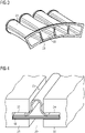
- the figure 1 shows in a three-dimensional sketch an example for an inventive seal 01.
- the seal is intentionally arranged at a gap 20, wherein the seal 01 should prevent a flow from a second side 03 to a first side 02 or vice-versa.
- the seal 01 extends along the gap 20 and comprises a steal strap 05 as middle layer.
- the steal strap 05 has a flat shape and extends from a left side to a right side of the seal 01.
- On the first side 02 a first metal web 08 is attached to the steal strap 05.
- On the right side and on the left side of the seal 01 a left tab 06 respectively a right tab 07 is attached to the steal strap 05, which both extend to the first side 02 and therefore cover the sides of the first metal web 08.
- a second metal web 11 is attached to the steal strap 05.
- the second metal web 11 comprises a convex arch portion 12 between a left flat shaped portion 13 and a right flat shaped portion 14.
- the flat shaped portions 13, 14 are attached directly to the steal strap 05.
- the left flat shaped portion 13 is connected with the convex arch portion 12 by a left concave bend portion 15
- the right flat shaped portion 14 is connected with the convex arch portion 12 by a right concave bend portion 16.
- the change of the bending from the convex shape of the bend portions 15, 16 to the concave shape of the arch portion 12 defines a turning line 17.
- spot-welded joints 09 are shown on the second side 03.
- the same spot-welded joints are applied on the first side 02 (not visible).
- the spot-welded joints 09 the three layers 05, 08, 13, 14 are fixed together.
- the figure 2 shows a sketch of the section cut through the seal 01 with the first side 02 of the seal 01 on the bottom side of the figure and the second side 03 of the seal 01 on the top side of the figure.
- the seal 01 comprises the steal strap 05 in the middle layer with the first metal web 08 on the first side 02 and the second metal web 11 on the second side 03.
- the second metal web 11 comprises the left flat shaped portion 13 connected to the left concave bend portion 15 connected to the convex arch portion 12 connected to the right concave bend portion 16, 36 connected to the right flat shaped portion 14.
- the junction from the concave bend portion 15, 16 to the convex arch portion 12 is represented by the turning line 17, in this view a turning point.
- the seal 01 has a seal width from the left side to the right side. It further comprises a seal thickness with the thickness of the steal strap 05 plus the thickness of the first metal web 08 and the thickness of the flat shaped portions 13, 14.
- the concave arch portion 12 is spaced apart from the steal strap 05.
- the seal 01 has a height, which is in this example about 0.5-times the seal width and about 6-times the seal thickness.
- the turning line 17 is arranged about in the middle of the height of the seal 01.
- the width of the convex arch portion 12 is in this example about a quarter of the seal width.
- the distance of the left flat portion 13 to the right flat portion 14 is about twice the width of the concave arch portion 12 and about halve of the seal width.
- transition ducts 21 In the figure 3 an example for an arrangement of transition ducts 21 is shown.
- further transition ducts are arranged in an annular arrangement around the rotor-axis.
- combustors In the combustion apparatus on the upstream side, which is the top-left side in the figure 3 , combustors are arranged and on the downstream side of the transition ducts 21, 22, which is the down-right side in the figure 3 , an expansion turbine is arranged.
- At the downstream end of the transition ducts 21, 22 they are arranged adjacent to each other with a gap 20 in-between. The gap extends mainly in radial direction in a combustion apparatus of a gas turbine.
- FIG 4 a detailed view on the gap 20 between the transition ducts 21, 22 with a further example of an inventive seal 01 is shown.
- the transition ducts 21, 22 each comprise at the gap a sealing groove 23, 24, which are arranged opposite to each other.
- the seal 01 is arranged in the gap 20 engaging into the sealing grooves 23, 24.
- a fourth metal web 18 could be applied on the first side 02 at the first metal web 08.
- a further embodiment of a seal 10 is shown. It 10 comprises analog a steal strap 05 with an opposite left tab 06 and right tab. On the first side 02 also a first metal web 08 is arranged. Against the solution shown in the previous figures this embodiment comprises two portions of a second metal web 31, 41 instead of one piece extending over the hole length. Therefore, a top portion of a second metal web 31 is arranged close to a first end of the seal 10 on the second side and a lower portion of the second metal web 41 is arranged close to the opposite second end of the seal 10.
- Both portions of the second metal web 31, 41 are design analog the second metal web 11 of the previous solution with an convex arch portion 32 in the middle extending to the second side 03 and attached a left concave bend portion 35 and a right concave bend portion followed by a left flat shaped portion 33 respectively a right flat shaped portion 34.
- a middle piece of the third metal web 42 is applied on the steal strap 05 between the portions of the second metal web 31, 41. Furthermore a top piece of the third metal web 43 is applied at the first end of the seal 10 on the steal strap 05 on the second side 03, wherein a lower piece of the third metal web 44 is applied at the opposite second end of the seal 10.
- the steal strap 05 is covered fully on the second side 03 with the portions of the second metal web 31, 41 together with the pieces of the third metal web 42, 43, 44.
- a hook portion 45 is applied on the first end of the seal 10, which is realized by a bend portion of the top piece of the third metal web 43.
Landscapes
- Engineering & Computer Science (AREA)
- General Engineering & Computer Science (AREA)
- Mechanical Engineering (AREA)
- Gasket Seals (AREA)
- Turbine Rotor Nozzle Sealing (AREA)
Description
- The invention relates to a seal for sealing a gap between adjacent parts in high temperature applications. The preferred application is the usage in a combustion apparatus of a gas turbine.
- In gas turbine engines combustion gasses with high temperature are conducted from the combustors to the expansion turbine next to the combustion apparatus. Common gas turbines comprise several can annular combustors arranged circumferentially around the rotor axis. To guide the combustion gases transition ducts are arranged between the combustors and the expansion turbine. Accordingly, the transition ducts are arranged also in an annular array, whereby at the downstream side of the transition ducts they are arranged close to each other with a gap between adjacent transition ducts. Due to tolerances and especially vibrations it is not possible to fit the transitions direct to each other without a gap. Therefore, effective sealing of the gap between adjacent transition ducts is desired.
- In this application a first side represents the side of the expansion turbine relative to the gap. In the usage at a combustion apparatus the first side is a lower-pressure hot side. Accordingly, the opposite side in the direction upstream of the transition ducts is the second side. In this arrangement of a combustion apparatus the second side is a higher-pressure cold side.
- One transition duct is arranged on the left side and the other transition duct is arrange on the right side relative to the gap.
- From the state of the art several solutions for sealing a gap between transition ducts are known. In the common solution the transition ducts comprise at its downstream end on the opposite sides of the gap a side groove extending mainly in radial direction. The side grooves of adjacent transition ducts are arranged in principle opposite to each other in a common plane, so that a flat side seal could be arranged in both grooves while closing the gap in-between.
- An exemplary known seal is built from a flat metal sheet on the second side, extending into the grooves, whereby the width of the seal is close to the distance of the opposite grounds of the grooves. Directly to the metal sheet a woven metallic mesh is attached with the same width as the metal sheet. In a further known arrangement a further second metal sheet is arranged on the opposite side of the metallic mesh.
- Different to the forgoing solution there are also side seals known from the state of the art, which comprises a metal sheet as a core piece, where a woven metallic mesh is wrapped around the metal sheet. As result the side seal comprises a first layer of metallic mesh on the first side, a metal sheet as second layer and again a metallic mesh as third layer on the second side.
- A further sealing is known from
US 2016 0053627 A1 . It consists of a bended flat metal sheet, which as on both sides along the seal a flat portion and an omega-shape between those both flat portions. This results in a high flexibility in all directions across the length of the seal. To enable a reliable mounting in grooves the omega-shaped sheet is attached on both sides to a further flat metal frame. - As the side seal is subject to wear and could limit the maintenance interval, there is always the request for a higher lifetime of the side seal.
- The task is solved by a design of an inventive seal according the teaching of claim 1. An inventive combustion apparatus is determined in claim 9. Further preferred solutions are explained in the dependent claims.
- The generic seal is used for sealing a gap in high temperature application. Therefore, the generic seal is usually used in a combustion apparatus of a gas turbine. The seal extends along the path of the gap and comprises a first side and an opposite second side and further a left side and an opposite right side. In the direction from the left side to the right side, cross to the path of the gap, the seal further has a seal width. As the gap is not part of the seal itself (in this context with the definition of the seal), the gap is just used as a reference for a path respectively for a length.
- The generic seal comprises as a core member a steel strap. The steel strap extends at least along the gap and from the left side to the right side essentially over the seal width. Accordingly, the steel strap has a flat shape. It is relevant for the solution, that the steel strap is essentially without any cutouts and enables essentially the sealing of the gap. "Essentially" in this context means that the steel strap is first of all fluid tight from one margin of the seal over the seal width to the opposite margin and from one end of the gap respectively seal to the opposite end of the gap respectively seal. A solution with some holes inside the steel strap to enable a reduced/controlled flow through the seal is still covered by the invention, although a solution without holes is preferred.
- On the second side of the steel strap as another layer a second metal web is applied.
- The second metal web is fixed to the steel strap, whereby it is not relevant initially, which method is used to fix the layers to each other.
- The generic seal is further defined by a seal thickness, which is at least the thickness of the steel strap plus the thickness of the second metal web. Due to the common arrangement of the seal in opposite grooves of the transition ducts closing a gap in-between, the seal thickness is at most 0.2-times the seal width. It is further preferred to limit the seal thickness to 0.1-times of the seal width.
- An improvement against the common side seal the inventive solution of the seal uses a modified second metal web with a modified shape. Instead of a flat shape the second metal web comprises an Omega shape with a right flat shaped portion and a left flat shaped portion and a convex arch portion between the both flat shaped portions. As result not the complete second metal web is attached to the steel strap but only the both opposite flat shape portions, whereby the convex arch portion is spaced apart from the steel strap. Therefore, a seal height in a direction from the first side to the second side is much more than the seal thickness and at least 0.3-times of the seal width and at least 3-times the seal thickness. In a preferred embodiment the seal height is at least 0.4-times the seal width and/or at least 5-times the seal thickness.
- The new inventive seal with a convex arch portion at the second side, the mounting of the seal is improved and with a more precise positioning of the seal in the gap between the both transitions also the wear of the seal could be reduced further, which results in a longer inspection interval for the seal.
- In a preferred solution, on the first side of the steel strap a further layer with a first metal web is applied. The first metal web extends essentially along the gap and essentially over the seal width from the left side to the right side. Accordingly, the first metal web has also a flat shape. The first metal web is necessary also fixed to the steel strap, whereby it is not relevant initially, which method is used to fix the three layers to each other. In this case the seal thickness is defined by at least the thickness of the steel strap plus the thickness of the first metal web plus the thickness of the second metal web.
- A protection of the metal web on the left and/or right side and a reduction in the leakage flow through the gap could be reached if a right tab and a left tab are attached to both sides of the steal strap. In a first preferred embodiment, the right tab and/or the left tab extends from the steal strap to the first side covering the respective right and/or left side of the first metal web. In a second embodiment the right tab and/or the left tab extends from the steal strap to the second side covering the respective right and/or left side of the flat shaped portions. In a third embodiment the right tab and/or the left tab extends from the first side to the second side with the attachment to the steal strap in the middle of the tab.
- In the preferred solution the convex arch portion has a certain width compared to the intentional gap. Starting from the seal width as reference the width of the convex arch portion is at least 0.15-times and at most 0.4-times of the seal width. It is particular advantageous, if the width of the arch portion is at least 0.2-times and/or at most 0.3-times the seal width.
- In principle, it is possible to connect the convex arch portion with the flat shaped portions. As result a left and a right edge connects the arch portion with the flat shaped portions. But it is in particular advantageous to connect the convex arch portion with the right flat shaped portion and with the left shaped portion with a left concave bend portion and respective with a right concave bend portion. This enables a smooth curve from the right side to the left side of the second metal web.
- A preferred shape and forming of the second metal web could be reached, if the distance between the opposite flat shape portions is at least 1.5-times of the width of the arch portion. Here it is further advantageous, if the distance of the flat shape portions to each other is at most 0.7-times the seal width. This enables a good attachment of the second metal web to the steal strap and a reliable mounting of the seal at the gap. In a particular advantageous solution, the distance between the flat shaped portions is at least 2-times the width of the arch portion and/or at most 0.6-times the seal width.
- With the convex arch portion and the concave bend portions on both sides there is turning line, or in view of a section cut there is a turning point between the convex and the concave portion. In the preferred solution the turning line is about in the middle of the height of the seal. This is given, if the turning line is in the middle of the seal height or has from the middle a maximum deviation of 0.25-times of the seal height. This enables an advantageous production of the seal with the fixation of the second metal web at the steal strap and the shape is further advantageous when applied in the combustion apparatus in the gap between the adjacent transition ducts.
- Regarding the extension of the second metal web along the gap different solutions are possible. With a first embodiment the second metal web extends along the gap and over the seal width from the left side to the right side. As result the steal strap is covered on the second side with the second metal web over the essentially entire size over the length of the gap.
- In a second embodiment at least two portions of a second metal web are used. Here a top portion of a second metal web and a lower portion of a second metal web are applied on the steal strap on the second side, where the both portions are spaced apart from each other along the gap. Top and lower are arbitrarily chosen and are used for a location closer to the first end respectively to the opposite second of the seal spaced apart from the middle of the seal.
- This solution with two spaced portions of a second metal web are in most cases fully sufficient to ensure a correct mounting and fixation of the seal at the gap. And furthermore, there could be no damage of the curved second metal web at the middle portion of the seal, as there is no curved second metal web.
- Here it is further advantageous to apply at least one piece of a flat third metal web at the second side of the steal strap, where the portions of the second metal web is not located. This enables the coverage of the steal strap on the second side over the entire size at least over the length of the gap.
- It has to be noted, that it is not relevant, which shape or which further features the seal comprises at its first end or at the opposite second end outside of the gap, where there is nothing to seal. As result the seal could extend beyond the gap with the steal strap and with or without one or more metal webs.
- To enable a beneficial mounting of the seal at the gap it is further advantageous, if a hook portion is applied at the seal at the first or the second end. This needs to be located outside of the gap, where the hook portion should extend to the second side. The hook portion could advantageously realized as a bend portion at the steal strap or at the first metal web or in particular at a piece of the third metal web.
- As the second metal web with the convex arch portion is the key feature of the invention, the solution is not limited to only one metal web on the first side. It is also possible to apply a fourth metal web on the first side. This comprises also a flat shape and is attached to the first metal web.
- In this case the seal thickness is determined by the thickness of the steal strap plus the thickness of the first metal web plus the thickness of the flat shape portions plus the thickness of the fourth metal web.
- Instead of a fourth metal web it is also possible to apply a further steal strap at the first side.
- To fix the first metal web and the second metal web to the steal strap different solutions could be used, but in the preferred embodiment the first metal web and the flat shaped portions are connected to the steal strap with a number of spot-welded joints. The same applies for further pieces or portions of a metal web and also for a fourth metal web, if available.
- The inventive seal enables a new inventive combustion apparatus, which is preferably of a gas turbine.
- The generic combustion apparatus comprises at least a left transition duct and a right transition duct, wherein the transition ducts intentionally guide a flow of hot combustion gases from an upstream side, where combustors are arranged, to a downstream side, where an expansion turbine is arranged, if used in a gas turbine. The left transition duct comprises a left sealing groove and the right transition duct comprises a right sealing groove. The right transition duct and the left transition duct are arranged adjacent to each other with a gap in-between at the downstream end of the transition ducts. The sealing grooves are arranged opposite to each other at the gap. The gap is closed by a seal, which engages into the opposite sealing grooves.
- The inventive combustion apparatus uses an inventive seal according to the forgoing description.
- In the preferred solution the distance between the grounds of the sealing grooves is at least 1.1-times and at most 1.5-times of the seal width.
- It is further advantageous, if the width of the sealing grooves is at least 1.1-times of the thickness of the seal. Here it is further preferred, if the width of the sealing grooves is at most 2-times the thickness of the seal.
- Regarding the arrangement of the adjacent transition ducts to each other it is advantageous, if the width of the gap is at least 1.1-times the width of the convex arch portion. It is further preferred, if the width of the gap is at most 1.5-times the width of the arch portion to enable a preferred mounting of the seal in the gap. In a particular advantageous embodiment, the width of the gap is at least 1.2-times and/or at most 1.3-times the width of the convex arch portion.
- In the following figures examples for an inventive seal and its arrangement at adjacent transition ducts are shown.
- Fig. 1
- shows a three-dimensional sketch of a first example;
- Fig. 2
- shows a section cut of the seal of
Fig. 1 ; - Fig. 3
- shows an arrangement of transition ducts with a gap;
- Fig. 4
- shown in detail the arrangement of a second embodiment of a seal in the gap;
- Fig. 5
- shows a third embodiment of a seal with two portions of a second metal web.
- The
figure 1 shows in a three-dimensional sketch an example for aninventive seal 01. The seal is intentionally arranged at agap 20, wherein theseal 01 should prevent a flow from asecond side 03 to afirst side 02 or vice-versa. Theseal 01 extends along thegap 20 and comprises asteal strap 05 as middle layer. Thesteal strap 05 has a flat shape and extends from a left side to a right side of theseal 01. On the first side 02 afirst metal web 08 is attached to thesteal strap 05. On the right side and on the left side of the seal 01 aleft tab 06 respectively aright tab 07 is attached to thesteal strap 05, which both extend to thefirst side 02 and therefore cover the sides of thefirst metal web 08. - On the second side a
second metal web 11 is attached to thesteal strap 05. But different to thefist metal web 08 thesecond metal web 11 comprises a convexarch portion 12 between a left flat shapedportion 13 and a right flat shapedportion 14. The flat shapedportions steal strap 05. The left flat shapedportion 13 is connected with the convexarch portion 12 by a leftconcave bend portion 15 and the right flat shapedportion 14 is connected with the convexarch portion 12 by a rightconcave bend portion 16. The change of the bending from the convex shape of thebend portions arch portion 12 defines aturning line 17. - In the sketch further a number of spot-welded
joints 09 are shown on thesecond side 03. The same spot-welded joints are applied on the first side 02 (not visible). With the spot-weldedjoints 09 the threelayers - The
figure 2 shows a sketch of the section cut through theseal 01 with thefirst side 02 of theseal 01 on the bottom side of the figure and thesecond side 03 of theseal 01 on the top side of the figure. Theseal 01 comprises thesteal strap 05 in the middle layer with thefirst metal web 08 on thefirst side 02 and thesecond metal web 11 on thesecond side 03. Thesecond metal web 11 comprises the left flat shapedportion 13 connected to the leftconcave bend portion 15 connected to the convexarch portion 12 connected to the rightconcave bend portion 16, 36 connected to the right flat shapedportion 14. The junction from theconcave bend portion arch portion 12 is represented by the turningline 17, in this view a turning point. - The
seal 01 has a seal width from the left side to the right side. It further comprises a seal thickness with the thickness of thesteal strap 05 plus the thickness of thefirst metal web 08 and the thickness of the flat shapedportions arch portion 12 is spaced apart from thesteal strap 05. As result theseal 01 has a height, which is in this example about 0.5-times the seal width and about 6-times the seal thickness. The turningline 17 is arranged about in the middle of the height of theseal 01. The width of the convexarch portion 12 is in this example about a quarter of the seal width. The distance of the leftflat portion 13 to the rightflat portion 14 is about twice the width of the concavearch portion 12 and about halve of the seal width. - In the
figure 3 an example for an arrangement oftransition ducts 21 is shown. In usage at a combustion apparatus of a gas turbine further transition ducts are arranged in an annular arrangement around the rotor-axis. In the combustion apparatus on the upstream side, which is the top-left side in thefigure 3 , combustors are arranged and on the downstream side of thetransition ducts figure 3 , an expansion turbine is arranged. At the downstream end of thetransition ducts gap 20 in-between. The gap extends mainly in radial direction in a combustion apparatus of a gas turbine. - In the
figure 4 a detailed view on thegap 20 between thetransition ducts inventive seal 01 is shown. Thetransition ducts groove seal 01 is arranged in thegap 20 engaging into the sealinggrooves fourth metal web 18 could be applied on thefirst side 02 at thefirst metal web 08. - In the
figure 5 a further embodiment of aseal 10 is shown. It 10 comprises analog asteal strap 05 with an oppositeleft tab 06 and right tab. On thefirst side 02 also afirst metal web 08 is arranged. Against the solution shown in the previous figures this embodiment comprises two portions of asecond metal web second metal web 31 is arranged close to a first end of theseal 10 on the second side and a lower portion of thesecond metal web 41 is arranged close to the opposite second end of theseal 10. - Both portions of the
second metal web second metal web 11 of the previous solution with an convexarch portion 32 in the middle extending to thesecond side 03 and attached a leftconcave bend portion 35 and a right concave bend portion followed by a left flat shapedportion 33 respectively a right flat shapedportion 34. - To ensure a beneficial sealing with the
seal 10 the area beside the portions of thesecond metal web 31, 41 a middle piece of thethird metal web 42 is applied on thesteal strap 05 between the portions of thesecond metal web third metal web 43 is applied at the first end of theseal 10 on thesteal strap 05 on thesecond side 03, wherein a lower piece of thethird metal web 44 is applied at the opposite second end of theseal 10. As result also in this embodiment thesteal strap 05 is covered fully on thesecond side 03 with the portions of thesecond metal web third metal web - To enable the beneficial mounting a
hook portion 45 is applied on the first end of theseal 10, which is realized by a bend portion of the top piece of thethird metal web 43.
Claims (17)
- Seal (01, 10) for sealing intentional a gap (20) in high temperature application, in particular for a combustion apparatus of a gas turbine, with a first side (02) and an opposite second side (03) and a seal width cross to the path of the gap (20) comprising- a steel strap (05) with a flat shape and- a second metal web (11, 31,41) attached to the steel strap (05) on the second side (03),wherein the seal (01) has a seal thickness with at least the steel strap (05) plus the thickness of the second metal web (11, 31,41) and has a seal height, wherein the seal thickness is at most 0.2-times of the seal width, wherein the second metal web (11, 31,41) comprises an Omega shape and is attached on both sides with a flat shaped portion (13, 33,14, 34) to the steel strap (05) and comprises an convex arch portion (12, 32) between both flat portions (13, 33,14, 34), andwherein the seal height is at least 0.3-times of the seal width and at least 3-times of the seal thickness, characterized in that,the steel strap (05) with a flat shape extending in an essentially closed manner over the full length and width of the seal.
- Seal (01, 10) according to claim 1,
wherein
the seal thickness is at most 0.1-times of the seal width, and/or the seal height is at least 0.4-times of the seal width, and/or the seal height is at least 5-times of the seal thickness. - Seal (01, 10) according to claim 1 or 2,
further comprising
a first metal web (08) with a flat shape attached to the steel strap (05) on the first side (02), wherein the seal (01) has a seal thickness with at least the steel strap (05) plus the first metal web (08) plus the thickness of the second metal web (11, 31,41). - Seal (01, 10) according to claim 3,
wherein
the steal strap (05) is covered over the entire size at the first side (02) at least over the length of the gap (20), with the first metal web (08). - Seal (01, 10) according to one of the claims 1 to 4,
further comprising
a left tab (06) and a right tab (07) each attached to one side of the steal strap (05) covering the respective side of the first metal web (08) and/or of the flat shaped portion (13, 33,14, 34). - Seal (01, 10) according to one of the claims 1 to 5,
wherein
the width of the arch portion (12, 32) is at least 0.15, 35-times, in particular at least 0.2-times, and at most 0.4-times, in particular at most 0.3-times, of the seal width. - Seal (01, 10) according to one of the claims 1 to 6,
wherein
the second metal web (11, 31,41) comprises a left concave bend portion (15, 35) and a right concave bend portion (16, 36) each connecting a flat portion (13,14, 33,34) with the arch portion (12, 32). - Seal (01, 10) according to claim 7,
whereinthe distance between the flat portions (13,14, 33,34) is at least 1.5-times of the width of the arch portion (12, 32) and at most 0.7-times of the seal width; and/or whereinthe turning line (17) between the bend portions (15,16, 35,36) and the arch portion (12, 32) is in the middle of the height of the seal (01, 10) +/-25%. - Seal (01) according to one of the claims 1 to 8,
wherein
the steal strap (05) is covered over the entire size at the second side (03), at least over the length of the gap (20), with the second metal web (11). - Seal (10) according to one of the claims 1 to 8,
wherein
the second metal web consists of at least a top portion (31) and spaced apart of a lower portion (41). - Seal (10) according to claim 10,
wherein
the steal strap (05) is covered over the entire size at the second side (03), at least over the length of the gap (20), with the portions (31, 41) of the second metal web and with further flat pieces of metal web (42, 43, 44). - Seal (10) according to one of the claims 1 to 11,
wherein
the steal strap or one of the metal webs or one of the flat pieces of metal web (44) comprises a hook portion (45) outside of the gap (20) extending to the second side (03) . - Seal (01, 10) according to one of the claims 1 to 12,
wherein
the steel strap (05) and the metal webs (08, 11, 18) and pieces and/or portions of a metal web (31, 41, 42, 43, 44) are connected with a number of spot-welded joints. - Combustion apparatus with at least a left transition duct (21) and a right transition duct (22) each for guiding a hot combustion gas, wherein the transition ducts (21, 22) are adjacent to each other with a gap (20) in-between, each transition duct (21, 22) comprising a left respective right sealing groove (23, 24) opposite to each other, wherein a seal (01, 10) according to one of the preceding claims is arranged in the gap (20) engaging in the sealing grooves (23, 24).
- Combustion apparatus according to claim 14,
wherein
the distance between the grounds of the sealing grooves (23, 24) is at least 1.1-times and at most 1.5-times the seal width. - Combustion apparatus according to claim 14 or 15,
wherein
the width of the sealing grooves (23, 24) are at least 1.1-times the thickness of the seal (01, 10) and at most 2-times the thickness of the seal (01, 10). - Combustion apparatus according to one of the claims 14 to 16,
wherein
the width of the gap (20) is at least 1.1-times and at most 1.5-times the width of the arch portion (13, 33).
Applications Claiming Priority (3)
| Application Number | Priority Date | Filing Date | Title |
|---|---|---|---|
| US201962896008P | 2019-09-05 | 2019-09-05 | |
| EP19210381.0A EP3789638A1 (en) | 2019-09-05 | 2019-11-20 | Seal for combustion apparatus |
| PCT/EP2020/072086 WO2021043527A1 (en) | 2019-09-05 | 2020-08-06 | Seal for combustion apparatus |
Publications (2)
| Publication Number | Publication Date |
|---|---|
| EP3983703A1 EP3983703A1 (en) | 2022-04-20 |
| EP3983703B1 true EP3983703B1 (en) | 2023-01-25 |
Family
ID=68621168
Family Applications (2)
| Application Number | Title | Priority Date | Filing Date |
|---|---|---|---|
| EP19210381.0A Withdrawn EP3789638A1 (en) | 2019-09-05 | 2019-11-20 | Seal for combustion apparatus |
| EP20763988.1A Active EP3983703B1 (en) | 2019-09-05 | 2020-08-06 | Seal for combustion apparatus |
Family Applications Before (1)
| Application Number | Title | Priority Date | Filing Date |
|---|---|---|---|
| EP19210381.0A Withdrawn EP3789638A1 (en) | 2019-09-05 | 2019-11-20 | Seal for combustion apparatus |
Country Status (4)
| Country | Link |
|---|---|
| US (1) | US11746667B2 (en) |
| EP (2) | EP3789638A1 (en) |
| PL (1) | PL3983703T3 (en) |
| WO (1) | WO2021043527A1 (en) |
Family Cites Families (31)
| Publication number | Priority date | Publication date | Assignee | Title |
|---|---|---|---|---|
| GB2038961B (en) * | 1979-01-03 | 1983-05-11 | Nicholson T P | Ring seal |
| US4524980A (en) * | 1983-12-05 | 1985-06-25 | United Technologies Corporation | Intersecting feather seals for interlocking gas turbine vanes |
| US6199871B1 (en) * | 1998-09-02 | 2001-03-13 | General Electric Company | High excursion ring seal |
| US20030039542A1 (en) * | 2001-08-21 | 2003-02-27 | Cromer Robert Harold | Transition piece side sealing element and turbine assembly containing such seal |
| US6637751B2 (en) * | 2001-12-28 | 2003-10-28 | General Electric Company | Supplemental seal for the chordal hinge seals in a gas turbine |
| US6883807B2 (en) * | 2002-09-13 | 2005-04-26 | Seimens Westinghouse Power Corporation | Multidirectional turbine shim seal |
| GB0228748D0 (en) * | 2002-12-10 | 2003-01-15 | Alstom Switzerland Ltd | Sealing arrangement |
| US8695989B2 (en) * | 2004-04-30 | 2014-04-15 | Siemens Aktiengesellschaft | Hot gas seal |
| JP4822716B2 (en) * | 2005-02-07 | 2011-11-24 | 三菱重工業株式会社 | Gas turbine with seal structure |
| US7670108B2 (en) * | 2006-11-21 | 2010-03-02 | Siemens Energy, Inc. | Air seal unit adapted to be positioned adjacent blade structure in a gas turbine |
| FR2913718B1 (en) * | 2007-03-15 | 2009-06-05 | Snecma Propulsion Solide Sa | TURBINE RING ASSEMBLY FOR GAS TURBINE |
| US8182208B2 (en) * | 2007-07-10 | 2012-05-22 | United Technologies Corp. | Gas turbine systems involving feather seals |
| US8308428B2 (en) * | 2007-10-09 | 2012-11-13 | United Technologies Corporation | Seal assembly retention feature and assembly method |
| US8240985B2 (en) * | 2008-04-29 | 2012-08-14 | Pratt & Whitney Canada Corp. | Shroud segment arrangement for gas turbine engines |
| US8142142B2 (en) | 2008-09-05 | 2012-03-27 | Siemens Energy, Inc. | Turbine transition duct apparatus |
| US8398090B2 (en) * | 2010-06-09 | 2013-03-19 | General Electric Company | Spring loaded seal assembly for turbines |
| US8678754B2 (en) * | 2011-01-24 | 2014-03-25 | General Electric Company | Assembly for preventing fluid flow |
| US20130028713A1 (en) * | 2011-07-25 | 2013-01-31 | General Electric Company | Seal for turbomachine segments |
| US9353635B2 (en) | 2011-08-16 | 2016-05-31 | General Electric Company | Seal end attachment |
| WO2014186001A2 (en) * | 2013-04-12 | 2014-11-20 | United Technologies Corporation | Flexible feather seal for blade outer air seal gas turbine engine rapid response clearance control system |
| US9677427B2 (en) * | 2014-07-04 | 2017-06-13 | Pratt & Whitney Canada Corp. | Axial retaining ring for turbine vanes |
| EP3267010B1 (en) * | 2015-03-05 | 2019-05-08 | Mitsubishi Heavy Industries Engine & Turbocharger, Ltd. | Turbocharger |
| US9759079B2 (en) * | 2015-05-28 | 2017-09-12 | Rolls-Royce Corporation | Split line flow path seals |
| US10370992B2 (en) * | 2016-02-24 | 2019-08-06 | United Technologies Corporation | Seal with integral assembly clip and method of sealing |
| US10202863B2 (en) * | 2016-05-23 | 2019-02-12 | United Technologies Corporation | Seal ring for gas turbine engines |
| US10450883B2 (en) * | 2016-10-31 | 2019-10-22 | United Technologies Corporation | W-seal shield for interrupted cavity |
| US10746038B2 (en) * | 2016-11-17 | 2020-08-18 | Raytheon Technologies Corporation | Airfoil with airfoil piece having radial seal |
| US10301955B2 (en) * | 2016-11-29 | 2019-05-28 | Rolls-Royce North American Technologies Inc. | Seal assembly for gas turbine engine components |
| US11208907B2 (en) * | 2017-07-13 | 2021-12-28 | Raytheon Technologies Corporation | Seals and methods of making seals |
| US11156116B2 (en) * | 2019-04-08 | 2021-10-26 | Honeywell International Inc. | Turbine nozzle with reduced leakage feather seals |
| US11187094B2 (en) * | 2019-08-26 | 2021-11-30 | General Electric Company | Spline for a turbine engine |
-
2019
- 2019-11-20 EP EP19210381.0A patent/EP3789638A1/en not_active Withdrawn
-
2020
- 2020-08-06 US US17/634,969 patent/US11746667B2/en active Active
- 2020-08-06 PL PL20763988.1T patent/PL3983703T3/en unknown
- 2020-08-06 WO PCT/EP2020/072086 patent/WO2021043527A1/en not_active Ceased
- 2020-08-06 EP EP20763988.1A patent/EP3983703B1/en active Active
Also Published As
| Publication number | Publication date |
|---|---|
| US11746667B2 (en) | 2023-09-05 |
| US20220389827A1 (en) | 2022-12-08 |
| EP3983703A1 (en) | 2022-04-20 |
| WO2021043527A1 (en) | 2021-03-11 |
| EP3789638A1 (en) | 2021-03-10 |
| PL3983703T3 (en) | 2023-05-22 |
Similar Documents
| Publication | Publication Date | Title |
|---|---|---|
| US11111823B2 (en) | Turbine ring assembly with inter-sector sealing | |
| US6659472B2 (en) | Seal for gas turbine nozzle and shroud interface | |
| JP4594527B2 (en) | Nested bridge seal | |
| JP5038789B2 (en) | Seal assembly and rotary machine with "L" shaped butt gap seal between segments | |
| RU2233985C2 (en) | C-ring seal (versions) | |
| EP2514925B1 (en) | Ceramix matirx composite shroud attachement system | |
| US7080513B2 (en) | Seal element for sealing a gap and combustion turbine having a seal element | |
| US8105024B2 (en) | Seal in gas turbine | |
| US20050179215A1 (en) | Seal device | |
| US10830103B2 (en) | Expansion joint and methods of assembling the same | |
| EP2914814B1 (en) | Belly band seal with underlapping ends | |
| CN1556893A (en) | Device for keeping the sealing strip connected | |
| US20090322039A1 (en) | Sealing system for exhaust-gas lines | |
| JP7149807B2 (en) | gas turbine combustor | |
| RU2633319C2 (en) | Fixing and sealing ring reflectors | |
| JP2003097220A (en) | Transition piece side seal elements and turbine assemblies including such seals | |
| US20140062032A1 (en) | Spring-loaded seal assembly | |
| US5013072A (en) | Articulated tube connection, in particular for the exhaust pipework of a motor vehicle | |
| US9677454B2 (en) | Gasket | |
| CN109424443A (en) | Gas turbine | |
| US11746667B2 (en) | Seal for combustion apparatus | |
| WO2015010740A1 (en) | Sealing arrangement for a turbomachine | |
| JP2007120340A (en) | Combustor tail pipe seal structure of gas turbine | |
| US20210332712A1 (en) | Seal segment for a turbine, assembly for externally delimiting a flow path of a turbine, and stator/rotor seal | |
| US10982769B2 (en) | Flat gasket and internal combustion engine |
Legal Events
| Date | Code | Title | Description |
|---|---|---|---|
| STAA | Information on the status of an ep patent application or granted ep patent |
Free format text: STATUS: UNKNOWN |
|
| STAA | Information on the status of an ep patent application or granted ep patent |
Free format text: STATUS: THE INTERNATIONAL PUBLICATION HAS BEEN MADE |
|
| PUAI | Public reference made under article 153(3) epc to a published international application that has entered the european phase |
Free format text: ORIGINAL CODE: 0009012 |
|
| STAA | Information on the status of an ep patent application or granted ep patent |
Free format text: STATUS: REQUEST FOR EXAMINATION WAS MADE |
|
| 17P | Request for examination filed |
Effective date: 20220113 |
|
| AK | Designated contracting states |
Kind code of ref document: A1 Designated state(s): AL AT BE BG CH CY CZ DE DK EE ES FI FR GB GR HR HU IE IS IT LI LT LU LV MC MK MT NL NO PL PT RO RS SE SI SK SM TR |
|
| GRAP | Despatch of communication of intention to grant a patent |
Free format text: ORIGINAL CODE: EPIDOSNIGR1 |
|
| STAA | Information on the status of an ep patent application or granted ep patent |
Free format text: STATUS: GRANT OF PATENT IS INTENDED |
|
| GRAJ | Information related to disapproval of communication of intention to grant by the applicant or resumption of examination proceedings by the epo deleted |
Free format text: ORIGINAL CODE: EPIDOSDIGR1 |
|
| STAA | Information on the status of an ep patent application or granted ep patent |
Free format text: STATUS: REQUEST FOR EXAMINATION WAS MADE |
|
| INTG | Intention to grant announced |
Effective date: 20220610 |
|
| INTC | Intention to grant announced (deleted) | ||
| GRAP | Despatch of communication of intention to grant a patent |
Free format text: ORIGINAL CODE: EPIDOSNIGR1 |
|
| STAA | Information on the status of an ep patent application or granted ep patent |
Free format text: STATUS: GRANT OF PATENT IS INTENDED |
|
| DAV | Request for validation of the european patent (deleted) | ||
| DAX | Request for extension of the european patent (deleted) | ||
| INTG | Intention to grant announced |
Effective date: 20220824 |
|
| GRAS | Grant fee paid |
Free format text: ORIGINAL CODE: EPIDOSNIGR3 |
|
| GRAA | (expected) grant |
Free format text: ORIGINAL CODE: 0009210 |
|
| STAA | Information on the status of an ep patent application or granted ep patent |
Free format text: STATUS: THE PATENT HAS BEEN GRANTED |
|
| AK | Designated contracting states |
Kind code of ref document: B1 Designated state(s): AL AT BE BG CH CY CZ DE DK EE ES FI FR GB GR HR HU IE IS IT LI LT LU LV MC MK MT NL NO PL PT RO RS SE SI SK SM TR |
|
| REG | Reference to a national code |
Ref country code: GB Ref legal event code: FG4D |
|
| REG | Reference to a national code |
Ref country code: CH Ref legal event code: EP |
|
| REG | Reference to a national code |
Ref country code: DE Ref legal event code: R096 Ref document number: 602020007887 Country of ref document: DE |
|
| REG | Reference to a national code |
Ref country code: AT Ref legal event code: REF Ref document number: 1546111 Country of ref document: AT Kind code of ref document: T Effective date: 20230215 Ref country code: IE Ref legal event code: FG4D |
|
| REG | Reference to a national code |
Ref country code: LT Ref legal event code: MG9D |
|
| REG | Reference to a national code |
Ref country code: NL Ref legal event code: MP Effective date: 20230125 |
|
| REG | Reference to a national code |
Ref country code: AT Ref legal event code: MK05 Ref document number: 1546111 Country of ref document: AT Kind code of ref document: T Effective date: 20230125 |
|
| PG25 | Lapsed in a contracting state [announced via postgrant information from national office to epo] |
Ref country code: NL Free format text: LAPSE BECAUSE OF FAILURE TO SUBMIT A TRANSLATION OF THE DESCRIPTION OR TO PAY THE FEE WITHIN THE PRESCRIBED TIME-LIMIT Effective date: 20230125 |
|
| PG25 | Lapsed in a contracting state [announced via postgrant information from national office to epo] |
Ref country code: RS Free format text: LAPSE BECAUSE OF FAILURE TO SUBMIT A TRANSLATION OF THE DESCRIPTION OR TO PAY THE FEE WITHIN THE PRESCRIBED TIME-LIMIT Effective date: 20230125 Ref country code: PT Free format text: LAPSE BECAUSE OF FAILURE TO SUBMIT A TRANSLATION OF THE DESCRIPTION OR TO PAY THE FEE WITHIN THE PRESCRIBED TIME-LIMIT Effective date: 20230525 Ref country code: NO Free format text: LAPSE BECAUSE OF FAILURE TO SUBMIT A TRANSLATION OF THE DESCRIPTION OR TO PAY THE FEE WITHIN THE PRESCRIBED TIME-LIMIT Effective date: 20230425 Ref country code: LV Free format text: LAPSE BECAUSE OF FAILURE TO SUBMIT A TRANSLATION OF THE DESCRIPTION OR TO PAY THE FEE WITHIN THE PRESCRIBED TIME-LIMIT Effective date: 20230125 Ref country code: LT Free format text: LAPSE BECAUSE OF FAILURE TO SUBMIT A TRANSLATION OF THE DESCRIPTION OR TO PAY THE FEE WITHIN THE PRESCRIBED TIME-LIMIT Effective date: 20230125 Ref country code: HR Free format text: LAPSE BECAUSE OF FAILURE TO SUBMIT A TRANSLATION OF THE DESCRIPTION OR TO PAY THE FEE WITHIN THE PRESCRIBED TIME-LIMIT Effective date: 20230125 Ref country code: ES Free format text: LAPSE BECAUSE OF FAILURE TO SUBMIT A TRANSLATION OF THE DESCRIPTION OR TO PAY THE FEE WITHIN THE PRESCRIBED TIME-LIMIT Effective date: 20230125 Ref country code: AT Free format text: LAPSE BECAUSE OF FAILURE TO SUBMIT A TRANSLATION OF THE DESCRIPTION OR TO PAY THE FEE WITHIN THE PRESCRIBED TIME-LIMIT Effective date: 20230125 |
|
| PG25 | Lapsed in a contracting state [announced via postgrant information from national office to epo] |
Ref country code: SE Free format text: LAPSE BECAUSE OF FAILURE TO SUBMIT A TRANSLATION OF THE DESCRIPTION OR TO PAY THE FEE WITHIN THE PRESCRIBED TIME-LIMIT Effective date: 20230125 Ref country code: IS Free format text: LAPSE BECAUSE OF FAILURE TO SUBMIT A TRANSLATION OF THE DESCRIPTION OR TO PAY THE FEE WITHIN THE PRESCRIBED TIME-LIMIT Effective date: 20230525 Ref country code: GR Free format text: LAPSE BECAUSE OF FAILURE TO SUBMIT A TRANSLATION OF THE DESCRIPTION OR TO PAY THE FEE WITHIN THE PRESCRIBED TIME-LIMIT Effective date: 20230426 Ref country code: FI Free format text: LAPSE BECAUSE OF FAILURE TO SUBMIT A TRANSLATION OF THE DESCRIPTION OR TO PAY THE FEE WITHIN THE PRESCRIBED TIME-LIMIT Effective date: 20230125 |
|
| REG | Reference to a national code |
Ref country code: DE Ref legal event code: R097 Ref document number: 602020007887 Country of ref document: DE |
|
| PG25 | Lapsed in a contracting state [announced via postgrant information from national office to epo] |
Ref country code: SM Free format text: LAPSE BECAUSE OF FAILURE TO SUBMIT A TRANSLATION OF THE DESCRIPTION OR TO PAY THE FEE WITHIN THE PRESCRIBED TIME-LIMIT Effective date: 20230125 Ref country code: RO Free format text: LAPSE BECAUSE OF FAILURE TO SUBMIT A TRANSLATION OF THE DESCRIPTION OR TO PAY THE FEE WITHIN THE PRESCRIBED TIME-LIMIT Effective date: 20230125 Ref country code: EE Free format text: LAPSE BECAUSE OF FAILURE TO SUBMIT A TRANSLATION OF THE DESCRIPTION OR TO PAY THE FEE WITHIN THE PRESCRIBED TIME-LIMIT Effective date: 20230125 Ref country code: DK Free format text: LAPSE BECAUSE OF FAILURE TO SUBMIT A TRANSLATION OF THE DESCRIPTION OR TO PAY THE FEE WITHIN THE PRESCRIBED TIME-LIMIT Effective date: 20230125 Ref country code: CZ Free format text: LAPSE BECAUSE OF FAILURE TO SUBMIT A TRANSLATION OF THE DESCRIPTION OR TO PAY THE FEE WITHIN THE PRESCRIBED TIME-LIMIT Effective date: 20230125 |
|
| PG25 | Lapsed in a contracting state [announced via postgrant information from national office to epo] |
Ref country code: SK Free format text: LAPSE BECAUSE OF FAILURE TO SUBMIT A TRANSLATION OF THE DESCRIPTION OR TO PAY THE FEE WITHIN THE PRESCRIBED TIME-LIMIT Effective date: 20230125 |
|
| PLBE | No opposition filed within time limit |
Free format text: ORIGINAL CODE: 0009261 |
|
| STAA | Information on the status of an ep patent application or granted ep patent |
Free format text: STATUS: NO OPPOSITION FILED WITHIN TIME LIMIT |
|
| 26N | No opposition filed |
Effective date: 20231026 |
|
| PG25 | Lapsed in a contracting state [announced via postgrant information from national office to epo] |
Ref country code: SI Free format text: LAPSE BECAUSE OF FAILURE TO SUBMIT A TRANSLATION OF THE DESCRIPTION OR TO PAY THE FEE WITHIN THE PRESCRIBED TIME-LIMIT Effective date: 20230125 |
|
| PG25 | Lapsed in a contracting state [announced via postgrant information from national office to epo] |
Ref country code: MC Free format text: LAPSE BECAUSE OF FAILURE TO SUBMIT A TRANSLATION OF THE DESCRIPTION OR TO PAY THE FEE WITHIN THE PRESCRIBED TIME-LIMIT Effective date: 20230125 |
|
| PG25 | Lapsed in a contracting state [announced via postgrant information from national office to epo] |
Ref country code: MC Free format text: LAPSE BECAUSE OF FAILURE TO SUBMIT A TRANSLATION OF THE DESCRIPTION OR TO PAY THE FEE WITHIN THE PRESCRIBED TIME-LIMIT Effective date: 20230125 |
|
| PG25 | Lapsed in a contracting state [announced via postgrant information from national office to epo] |
Ref country code: LU Free format text: LAPSE BECAUSE OF NON-PAYMENT OF DUE FEES Effective date: 20230806 |
|
| PG25 | Lapsed in a contracting state [announced via postgrant information from national office to epo] |
Ref country code: LU Free format text: LAPSE BECAUSE OF NON-PAYMENT OF DUE FEES Effective date: 20230806 |
|
| REG | Reference to a national code |
Ref country code: BE Ref legal event code: MM Effective date: 20230831 |
|
| REG | Reference to a national code |
Ref country code: IE Ref legal event code: MM4A |
|
| PG25 | Lapsed in a contracting state [announced via postgrant information from national office to epo] |
Ref country code: IE Free format text: LAPSE BECAUSE OF NON-PAYMENT OF DUE FEES Effective date: 20230806 |
|
| PG25 | Lapsed in a contracting state [announced via postgrant information from national office to epo] |
Ref country code: IE Free format text: LAPSE BECAUSE OF NON-PAYMENT OF DUE FEES Effective date: 20230806 |
|
| PG25 | Lapsed in a contracting state [announced via postgrant information from national office to epo] |
Ref country code: BE Free format text: LAPSE BECAUSE OF NON-PAYMENT OF DUE FEES Effective date: 20230831 |
|
| PG25 | Lapsed in a contracting state [announced via postgrant information from national office to epo] |
Ref country code: BG Free format text: LAPSE BECAUSE OF FAILURE TO SUBMIT A TRANSLATION OF THE DESCRIPTION OR TO PAY THE FEE WITHIN THE PRESCRIBED TIME-LIMIT Effective date: 20230125 |
|
| PG25 | Lapsed in a contracting state [announced via postgrant information from national office to epo] |
Ref country code: BG Free format text: LAPSE BECAUSE OF FAILURE TO SUBMIT A TRANSLATION OF THE DESCRIPTION OR TO PAY THE FEE WITHIN THE PRESCRIBED TIME-LIMIT Effective date: 20230125 |
|
| PG25 | Lapsed in a contracting state [announced via postgrant information from national office to epo] |
Ref country code: CY Free format text: LAPSE BECAUSE OF FAILURE TO SUBMIT A TRANSLATION OF THE DESCRIPTION OR TO PAY THE FEE WITHIN THE PRESCRIBED TIME-LIMIT; INVALID AB INITIO Effective date: 20200806 |
|
| PG25 | Lapsed in a contracting state [announced via postgrant information from national office to epo] |
Ref country code: HU Free format text: LAPSE BECAUSE OF FAILURE TO SUBMIT A TRANSLATION OF THE DESCRIPTION OR TO PAY THE FEE WITHIN THE PRESCRIBED TIME-LIMIT; INVALID AB INITIO Effective date: 20200806 |
|
| PGFP | Annual fee paid to national office [announced via postgrant information from national office to epo] |
Ref country code: DE Payment date: 20250827 Year of fee payment: 6 |
|
| PGFP | Annual fee paid to national office [announced via postgrant information from national office to epo] |
Ref country code: TR Payment date: 20250718 Year of fee payment: 6 Ref country code: IT Payment date: 20250825 Year of fee payment: 6 Ref country code: PL Payment date: 20250714 Year of fee payment: 6 |
|
| PGFP | Annual fee paid to national office [announced via postgrant information from national office to epo] |
Ref country code: GB Payment date: 20250826 Year of fee payment: 6 |
|
| PGFP | Annual fee paid to national office [announced via postgrant information from national office to epo] |
Ref country code: FR Payment date: 20250825 Year of fee payment: 6 |
|
| PGFP | Annual fee paid to national office [announced via postgrant information from national office to epo] |
Ref country code: CH Payment date: 20250901 Year of fee payment: 6 |