EP3983672B1 - A method for controlling a wind farm under turbulent wind conditions - Google Patents
A method for controlling a wind farm under turbulent wind conditions Download PDFInfo
- Publication number
- EP3983672B1 EP3983672B1 EP20730570.7A EP20730570A EP3983672B1 EP 3983672 B1 EP3983672 B1 EP 3983672B1 EP 20730570 A EP20730570 A EP 20730570A EP 3983672 B1 EP3983672 B1 EP 3983672B1
- Authority
- EP
- European Patent Office
- Prior art keywords
- wind
- upstream
- turbines
- wind turbine
- downstream
- Prior art date
- Legal status (The legal status is an assumption and is not a legal conclusion. Google has not performed a legal analysis and makes no representation as to the accuracy of the status listed.)
- Active
Links
Images



Classifications
-
- F—MECHANICAL ENGINEERING; LIGHTING; HEATING; WEAPONS; BLASTING
- F03—MACHINES OR ENGINES FOR LIQUIDS; WIND, SPRING, OR WEIGHT MOTORS; PRODUCING MECHANICAL POWER OR A REACTIVE PROPULSIVE THRUST, NOT OTHERWISE PROVIDED FOR
- F03D—WIND MOTORS
- F03D7/00—Controlling wind motors
- F03D7/02—Controlling wind motors the wind motors having rotation axis substantially parallel to the air flow entering the rotor
- F03D7/04—Automatic control; Regulation
- F03D7/042—Automatic control; Regulation by means of an electrical or electronic controller
- F03D7/048—Automatic control; Regulation by means of an electrical or electronic controller controlling wind farms
-
- F—MECHANICAL ENGINEERING; LIGHTING; HEATING; WEAPONS; BLASTING
- F03—MACHINES OR ENGINES FOR LIQUIDS; WIND, SPRING, OR WEIGHT MOTORS; PRODUCING MECHANICAL POWER OR A REACTIVE PROPULSIVE THRUST, NOT OTHERWISE PROVIDED FOR
- F03D—WIND MOTORS
- F03D9/00—Adaptations of wind motors for special use; Combinations of wind motors with apparatus driven thereby; Wind motors specially adapted for installation in particular locations
- F03D9/30—Wind motors specially adapted for installation in particular locations
- F03D9/48—Wind motors specially adapted for installation in particular locations using landscape topography, e.g. valleys
-
- F—MECHANICAL ENGINEERING; LIGHTING; HEATING; WEAPONS; BLASTING
- F05—INDEXING SCHEMES RELATING TO ENGINES OR PUMPS IN VARIOUS SUBCLASSES OF CLASSES F01-F04
- F05B—INDEXING SCHEME RELATING TO WIND, SPRING, WEIGHT, INERTIA OR LIKE MOTORS, TO MACHINES OR ENGINES FOR LIQUIDS COVERED BY SUBCLASSES F03B, F03D AND F03G
- F05B2270/00—Control
- F05B2270/30—Control parameters, e.g. input parameters
- F05B2270/32—Wind speeds
-
- F—MECHANICAL ENGINEERING; LIGHTING; HEATING; WEAPONS; BLASTING
- F05—INDEXING SCHEMES RELATING TO ENGINES OR PUMPS IN VARIOUS SUBCLASSES OF CLASSES F01-F04
- F05B—INDEXING SCHEME RELATING TO WIND, SPRING, WEIGHT, INERTIA OR LIKE MOTORS, TO MACHINES OR ENGINES FOR LIQUIDS COVERED BY SUBCLASSES F03B, F03D AND F03G
- F05B2270/00—Control
- F05B2270/30—Control parameters, e.g. input parameters
- F05B2270/321—Wind directions
-
- Y—GENERAL TAGGING OF NEW TECHNOLOGICAL DEVELOPMENTS; GENERAL TAGGING OF CROSS-SECTIONAL TECHNOLOGIES SPANNING OVER SEVERAL SECTIONS OF THE IPC; TECHNICAL SUBJECTS COVERED BY FORMER USPC CROSS-REFERENCE ART COLLECTIONS [XRACs] AND DIGESTS
- Y02—TECHNOLOGIES OR APPLICATIONS FOR MITIGATION OR ADAPTATION AGAINST CLIMATE CHANGE
- Y02B—CLIMATE CHANGE MITIGATION TECHNOLOGIES RELATED TO BUILDINGS, e.g. HOUSING, HOUSE APPLIANCES OR RELATED END-USER APPLICATIONS
- Y02B10/00—Integration of renewable energy sources in buildings
- Y02B10/30—Wind power
-
- Y—GENERAL TAGGING OF NEW TECHNOLOGICAL DEVELOPMENTS; GENERAL TAGGING OF CROSS-SECTIONAL TECHNOLOGIES SPANNING OVER SEVERAL SECTIONS OF THE IPC; TECHNICAL SUBJECTS COVERED BY FORMER USPC CROSS-REFERENCE ART COLLECTIONS [XRACs] AND DIGESTS
- Y02—TECHNOLOGIES OR APPLICATIONS FOR MITIGATION OR ADAPTATION AGAINST CLIMATE CHANGE
- Y02E—REDUCTION OF GREENHOUSE GAS [GHG] EMISSIONS, RELATED TO ENERGY GENERATION, TRANSMISSION OR DISTRIBUTION
- Y02E10/00—Energy generation through renewable energy sources
- Y02E10/70—Wind energy
- Y02E10/72—Wind turbines with rotation axis in wind direction
-
- Y—GENERAL TAGGING OF NEW TECHNOLOGICAL DEVELOPMENTS; GENERAL TAGGING OF CROSS-SECTIONAL TECHNOLOGIES SPANNING OVER SEVERAL SECTIONS OF THE IPC; TECHNICAL SUBJECTS COVERED BY FORMER USPC CROSS-REFERENCE ART COLLECTIONS [XRACs] AND DIGESTS
- Y02—TECHNOLOGIES OR APPLICATIONS FOR MITIGATION OR ADAPTATION AGAINST CLIMATE CHANGE
- Y02E—REDUCTION OF GREENHOUSE GAS [GHG] EMISSIONS, RELATED TO ENERGY GENERATION, TRANSMISSION OR DISTRIBUTION
- Y02E10/00—Energy generation through renewable energy sources
- Y02E10/70—Wind energy
- Y02E10/728—Onshore wind turbines
Definitions
- the present invention relates to a method for controlling wind turbines of a wind farm comprising a plurality of wind turbines under turbulent wind conditions.
- the method of the invention ensures that the most vulnerable wind turbines of the wind farm are protected.
- a plurality of wind turbines is positioned within a specified geographical area. Accordingly, at any given wind direction, some of the wind turbines will be arranged in front of some of the other wind turbines, as seen in the direction of the incoming wind.
- the wind turbines arranged in front may be referred to as 'upstream wind turbines', while the wind turbines arranged behind at least one other wind turbine may be referred to as 'downstream wind turbines' with respect to the wind turbines arranged in front thereof.
- US 2004/0258521 A1 and US 2014/0117668 A1 disclose an early-warning system for wind power installations, in which information is transmitted between individual wind power installations regarding environmental conditions. Wind conditions are measured at an individual wind power installation by means of anemometers or other sensors, and the measurement results are also used for other wind power installations which in the direction of the wind are arranged behind the first wind power installation. If necessary, for example when a gust or squall occurs, the other wind power installations can implement a change in their blade setting angle at a moment which is still in good time before the gust or squall hits the other wind power installations, and then, when the gust or squall hits the other wind power installations, the loading on them is not so great that it can still give rise to damage.
- the properties of the site are of such a nature that turbulence is introduced. This could, e.g., be due to the terrain of the site, e.g. in the form of hills and/or valleys, and/or it could be due to objects positioned at the site, such as buildings, vegetation, etc. In this case it might not be appropriate to apply measurements from an upstream wind turbine for controlling a downstream wind turbine, i.e. the method described in US 2004/0258521 A1 might be inappropriate.
- EP 3 263 889 A1 discloses a system and a method for assessing farm-level performance of a wind farm. The method includes operating the wind farm in an operational mode and identifying one or more pairs of wind turbines having wake interaction and generating a pairwise dataset. A wake model is generated based on the pairwise dataset.
- EP 2 940 296 A1 discloses a method and a system for optimizing operation of a wind farm.
- the method includes receiving new values corresponding to wake parameters for wind turbines in the wind farm and identifying new sets of interacting wind turbines based thereon.
- a farm-level predictive wake model is developed for the new sets of interacting wind turbines.
- the invention provides a method for controlling wind turbines of a wind farm comprising a plurality of wind turbines according to claim 1.
- the invention provides a method for controlling wind turbines of a wind farm.
- the term 'wind farm' should be interpreted to mean a plurality of wind turbines arranged within a limited geographical area, and which at least partly share infrastructure, such as substations, power grid connection, etc.
- the wind farm is position at a site which includes one or more turbulence generating structures.
- the term 'turbulence generating structure' should be interpreted to mean a structure which generates turbulence as wind passes across the structure.
- wind turbines positioned behind, or downstream relative to, a turbulence generating structure, as seen in the direction of the incoming wind will experience turbulence which is introduced by the turbulence generating structure, whereas wind turbines positioned in front of, or upstream relative to, the turbulence generating structure will not experience such turbulence.
- the turbulence generating structure could be a part of the terrain, such as a hill or a valley, vegetation, such as trees or the like, manmade structures, such as buildings, etc., as long as it has a size and a shape which results in turbulence being generated when the wind passes across the structure.
- a wind direction at the site of the wind farm is initially detected. This may be done by means of wind direction sensors mounted on one or more wind turbines of the wind farm, and/or on metmasts or the like arranged at the site of the wind farm or in the vicinity thereof.
- one or more upstream wind turbines and one or more downstream wind turbines are defined, based on the detected wind direction.
- the term 'upstream wind turbine' should be interpreted to mean a wind turbine which is arranged in front of at least one other wind turbine, as seen in the direction of the incoming wind.
- the term 'downstream wind turbine' should be interpreted to mean a wind turbine which is arranged behind at least one other wind turbine, as seen in the direction of the incoming wind.
- a given wind turbine is denoted an upstream wind turbine or a downstream wind turbine with respect to one or more other wind turbines depends on the wind direction.
- a given wind turbine may be an upstream wind turbine relative to one or more wind turbines and simultaneously be a downstream wind turbine relative to one or more other wind turbines.
- Detecting that turbulent wind conditions are occurring at the site of the wind farm is an indication that measures might be required for protecting one or more of the wind turbines of the wind farm against undesired loads caused by the turbulent wind conditions.
- at least one of the upstream wind turbines is controlled based on measurements performed by at least one wind turbine which is a downstream wind turbine relative to the upstream wind turbine.
- the upstream wind turbines in particular the turbines arranged at the boundary of the wind farm, are most vulnerable to variations in the incoming wind, for instance in the form of gusts, since they are not arranged in the wake of the other wind turbines.
- upstream wind turbines may be prone to tower strikes, i.e. collisions between wind turbine blades and wind turbine towers, in the case of gusty wind conditions.
- the step of controlling at least one of the upstream wind turbines may comprise derating the upstream wind turbine in the case that a wind speed measured by means of the at least one downstream wind turbine exceeds a predefined first threshold value.
- the measurements performed at the at least one downstream wind turbine include wind speed measurements, which could, e.g., be performed by means of anemometers mounted on the downstream wind turbines.
- the upstream wind turbine may be subjected to high loads due to the incoming wind. Accordingly, when this occurs, the upstream wind turbine may be derated, i.e. it may be operated with a decreased output power. This decreases the loads on the upstream wind turbine, and thereby protects it from excessive load impacts, while maintaining some power production from the upstream wind turbine.
- the first threshold value could, e.g., be within the range of 15 m/s to 25 m/s, such as within the range of 17 m/s to 22 m/s, such as approximately 20 m/s.
- the upstream wind turbine may be derated if the wind speed measured by at least one downstream wind turbine exceeds the wind speed measured by means of the upstream wind turbine by a certain wind speed difference, e.g. a wind speed difference within the range of 5 m/s to 15 m/s, such as within the range of 7 m/s to 12 m/s, such as approximately 10 m/s.
- a certain wind speed difference e.g. a wind speed difference within the range of 5 m/s to 15 m/s, such as within the range of 7 m/s to 12 m/s, such as approximately 10 m/s.
- the step of controlling at least one of the upstream wind turbines may comprise stopping the upstream wind turbine in the case that a wind speed measured by means of the at least one downstream wind turbine exceeds a predefined second threshold value.
- the second threshold value may be higher than the first threshold value.
- the upstream wind turbine is derated if the wind speed measured by the downstream wind turbine exceeds the first threshold value, and is stopped if the wind speed continues increasing to a level above the second, higher, threshold value. Stopping the upstream wind turbine provides further protection of the upstream wind turbine, but this comes at the cost that no power is produced by the upstream wind turbine.
- the second threshold value could, e.g., be within the range of 23 m/s to 33 m/s, such as within the range of 25 m/s to 30 m/s, such as approximately 28 m/s.
- the upstream wind turbine may be stopped if the wind speed measured by at least one downstream wind turbine exceeds a certain threshold value exceeds the wind speed measured by means of the upstream wind turbine by a certain wind speed difference, e.g. a wind speed difference within the range of 10 m/s to 20 m/s, such as within the range of 12 m/s to 17 m/s, such as approximately 15 m/s.
- a certain wind speed difference e.g. a wind speed difference within the range of 10 m/s to 20 m/s, such as within the range of 12 m/s to 17 m/s, such as approximately 15 m/s.
- the relevant threshold value has been exceeded for a predefined period of time before the upstream wind turbine is derated or stopped, in order to avoid derating or stopping the upstream wind turbine if the threshold value is only exceeded very briefly.
- the step of detecting that turbulent wind conditions are occurring may be performed on the basis of wind speed measurements performed by at least two of the wind turbines of the wind farm. If turbulent wind conditions are occurring, it may be expected that the wind speed varies across the site of the wind farm. Accordingly, by measuring the wind speed by at least two of the wind turbines of the wind farm, and thereby at at least two different positions within the site of the wind farm, it can be derived whether or not turbulent wind conditions are occurring.
- the step of detecting that turbulent wind conditions are occurring may comprise the steps of:
- the wind speed is measured by means of an upstream wind turbine and by means of a downstream wind turbine, i.e. by at least two wind turbines where one of the wind turbines is arranged in front of the other wind turbine, as seen in the direction of the incoming wind.
- the two wind speed measurements are compared, and if it is revealed that the wind speed measured by means of the downstream wind turbine exceeds the wind speed measured by means of the upstream wind turbine by a predefined wind speed difference, it is determined that turbulent wind conditions are occurring.
- the turbulence may lead to wind speeds measured at downstream positions being higher than wind speed measured at upstream positions.
- this is a good indication that turbulent wind conditions are occurring.
- At least one turbulence generating structure may form part of a terrain of the site of the wind farm.
- the turbulence is generated as a result of properties of the terrain at the site.
- the turbulence generating structure could, in this case, be a hill, a valley and/or any other suitable kind of terrain which will give rise to turbulence.
- the turbulence generating structure is a hill
- at least one of the upstream wind turbines may be positioned on top of the hill
- at least one of the downstream wind turbines may be positioned downhill relative to the upstream wind turbine.
- turbulence is generated in front of the hill, as seen in the direction of the incoming wind. This has the consequence that a part of the incoming wind which is not caught in front of the hill reaches the downstream wind turbine before the turbulent wind which is caught in front of the hill reaches the upstream wind turbine. Accordingly, if variations in the incoming wind, such as gusts, occur, this will be detected by the downstream wind turbine before the variations in the wind reach the upstream wind turbine, positioned on top of the hill.
- the upstream wind turbine can be controlled in a manner which takes the expected variations in the incoming wind into account, and appropriate measures, such as derating the upstream wind turbine, can be taken before the variations in the incoming wind reach the upstream wind turbine.
- the turbulence generating structure is a valley
- at least one of the upstream wind turbines may be positioned immediately behind the valley, as seen in the wind direction.
- part of the wind stream is caught in the valley in front of the upstream wind turbine, and part of the wind stream passes above the valley as well as the upstream wind turbine, but reaches the downstream wind turbine.
- variations in the wind are thereby detected by the downstream wind turbine before they reach the upstream wind turbine, and it is therefore appropriate to control the upstream wind turbine on the basis of measurements performed by the downstream wind turbine.
- At least one turbulence generating structure may be or form part of an object positioned at the site of the wind farm.
- objects could, e.g., be manmade structures, such as buildings, fences, etc.
- they could form part of the vegetation at the site of the wind farm, for instance trees, shrubbery, etc.
- the step of controlling at least one of the upstream wind turbines based on measurement performed by at least one wind turbine which is a downstream wind turbine relative to the upstream wind turbine may be performed only if the detected wind direction is within a predefined wind direction range.
- specific wind conditions are known to occur under certain circumstances. Such specific wind conditions are often related to a specific wind direction.
- An example of such specific wind conditions is the Bora which is a northern to north-eastern katabatic wind in the Adriatic Sea. Since such specific wind conditions may give rise to undesired variations in the wind pattern, which may require protection of the upstream wind turbines in the manner described above, it may be desirable to initiate the protection measures provided by the method of the invention when it is detected that the wind direction is within a wind direction range known to be associated with the specific wind conditions. In the case of the Bora, this would be north to north-east. However, when the wind direction is within any other wind direction range, protection of upstream wind turbines may not be required, and it may therefore not be necessary to perform the steps of the method according to the invention.
- the positions of the wind turbines may be such that upstream wind turbines in need of protection only exist at certain wind directions. In this case it may also only be relevant to perform the steps of the method according to the invention when the wind direction is within a corresponding wind direction range.
- the steps of the method according to the invention may be performed regardless of the wind direction.
- the step of detecting a wind direction may be performed on the basis of measurements performed by the wind turbines of the wind farm. Thereby it is ensured that the detected wind direction is indeed the wind direction prevailing at the site of the wind farm.
- the wind direction may be detected by means of equipment positioned outside, but in the vicinity of, the wind farm, based on satellite data and/or based on measurements performed by equipment, such as metmasts, positioned at the site of the wind farm.
- the method may further comprise the steps of:
- the upstream wind turbine is only controlled based on measurements performed by the at least one downstream wind turbine as long as the turbulent wind conditions are prevailing, and the upstream wind turbine is therefore in need of protection.
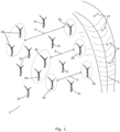
- Fig. 1 is a top view of a wind farm 1 comprising a plurality of wind turbines 2.
- the wind farm 1 is positioned at a site where the terrain defines a turbulence generating structure in the form of a hill 3.
- the current wind direction is illustrated by arrows 4.
- wind turbines 2a Three of the wind turbines 2a are positioned along a boundary of the wind farm 1 which faces the incoming wind 4. Thus, these wind turbines 2a arranged upstream with respect, i.e. in front of, the other wind turbines 2b, 2c of the wind farm 1, as seen in the direction of the incoming wind 4. Thus, these wind turbines 2a will in the following be referred to as 'upstream wind turbines' 2a.
- wind turbines 2b Five of the wind turbines 2b are positioned in such a manner that they are directly behind one of the upstream wind turbines 2a, as seen in the direction of the incoming wind 4. Thus, these wind turbines 2b are each arranged downstream relative to one of the upstream wind turbines 2a, as seen in the direction of the incoming wind 4. Accordingly, these wind turbines 2b will in the following be referred to as 'downstream wind turbines' 2b. Arrows 5 indicate how the upstream wind turbines 2a and the downstream wind turbines 2b are related to each other.
- the remaining wind turbines 2c of the wind farm 1 are positioned in such a manner that they are neither directly in front of, nor directly behind any of the other wind turbines 2, and they are therefore not used when performing the method according to the invention which will be described further below.
- the upstream wind turbines 2a are all positioned in the vicinity of and behind the hill 3, as seen in the direction of the incoming wind 4. Accordingly, the upstream wind turbines 2a are all affected by the turbulence generated by the hill 3. Accordingly, when it is determined that the wind direction 4 is as shown in Fig. 1 , the upstream wind turbines 2a may be in need of protection against adverse effects, e.g. caused by variations in the wind pattern.
- a wind speed measured by one or more downstream wind turbines 2b exceeds a wind speed measured by means of a corresponding upstream wind turbine by a predefined wind speed difference, this may be an indication that turbulent wind conditions are occurring at the site of the wind farm 1, and that there may therefore be a need to protect the upstream wind turbines 2a.
- each of the upstream wind turbines 2a is controlled based on measurements performed by at least one of the downstream wind turbines 2b related thereto. This will be described in further detail below with reference to Fig. 2 .
- Fig. 2 is a side view of the wind farm 1 of Fig. 1 , showing one upstream wind turbine 2a, one downstream wind turbine 2b and one wind turbine 2c which is neither designated as an upstream wind turbine nor as a downstream wind turbine. It can be seen that the upstream wind turbine 2a is positioned in the vicinity of the hill 3 and immediately adjacent to a valley 6 positioned between the hill 3 and a smaller hill 7 on which the upstream wind turbine 2a is positioned. It can be seen that the terrain including the hills 3, 7 and the valley 6 generates turbulence in the region immediately in front of the upstream wind turbine 2a, as seen in the direction of the incoming wind 4.
- the downstream wind turbine 2b is arranged further downhill than the upstream wind turbine 2a. This has the consequence that the part of the airstream which does not become turbulent due to the terrain passes above the upstream wind turbine 2a, but reaches the downstream wind turbine 2b.
- the results is that any variations in the wind pattern of the incoming wind stream, e.g. in the form of gusts, turbulence or a fast increase in wind speed, reaches the downstream wind turbine 2b before it reaches the upstream wind turbine 2a, despite the fact that the upstream wind turbine 2a is arranged in front of the downstream wind turbine 2b, as seen in the wind direction 4.
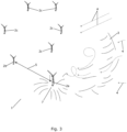
- Fig. 3 also illustrates a wind farm 1 comprising a plurality of wind turbines 2.
- the terrain at the site of the wind farm 1 of Fig. 3 differs from the site of the wind farm 1 of Figs. 1 and 2 in that the turbulence generating hill 3 arranged near the boundary of the wind farm 1 has a smaller extent than the hill 3 illustrated in Figs. 1 and 2 .
- An upstream wind turbine 2a is positioned on a smaller hill 7 and behind the higher, turbulence generating hill 3. Thereby the upstream wind turbine 2a is affected by the turbulence generated by the hill 3.
- a downstream wind turbine 2b is positioned in such a manner that it is not behind the hill 3, as seen in the direction of the incoming wind 4. Accordingly, the wind which reaches the downstream wind turbine 2b is unaffected by the hill 3.
- the downstream wind turbine 2b is furthermore not positioned directly behind the upstream wind turbine 2a as seen in the wind direction 4.
- Fig. 4 also illustrates a wind farm 1 comprising a plurality of wind turbines 2.
- One upstream wind turbine 2a, one downstream wind turbine 2b and ten wind turbines 2c which are neither designated as upstream wind turbines nor as downstream wind turbines are shown.
- the upstream wind turbine 2a is positioned immediately behind the trees 8, as seen in the direction of the incoming wind 4, and the upstream wind turbine 2a is therefore affected by the turbulence generated by the trees 8.
- the downstream wind turbine 2b is positioned directly behind the upstream wind turbine 2a, as seen in the wind direction 4. However, the distance between the upstream wind turbine 2a and the downstream wind turbine 2b is so long that the downstream wind turbine 2b is not affected by the turbulence generated by the trees 8. Similarly to the situation described above with reference to Figs. 1 and 2 , variations in the wind pattern of the incoming wind 4 will thereby reach the downstream wind turbine 2b before reaching the upstream wind turbine 2a. Accordingly, it is relevant to control the upstream wind turbine 2a based on measurements performed by the downstream wind turbine 2b.
- Fig. 5 also illustrates a wind farm 1 comprising a plurality of wind turbines 2.
- Two upstream wind turbines 2a, four downstream wind turbines 2b and eight wind turbines 2c which are neither designated as upstream wind turbines nor as downstream wind turbines are shown.
- At the site of the wind farm 1 of Fig. 5 there are neither hills and valleys, nor trees. Instead a number of manmade turbulence generating structure in the form of buildings 9 are positioned within the site.
- the upstream wind turbines 2a are positioned immediately behind the buildings 9, as seen in the direction of the incoming wind 4, and the upstream wind turbines 2a are therefore affected by the turbulence generated by the buildings 9.
- downstream wind turbines 2b are positioned behind the upstream wind turbines 2a, at a distance which is sufficient to ensure that the downstream wind turbines 2b are not affected by the turbulence generated by the buildings 9.
- variations in the wind pattern of the incoming wind 4 will reach the downstream wind turbines 2b before reaching the upstream wind turbines 2a, and it is therefore relevant to control the upstream wind turbines 2a based on measurements performed by the downstream wind turbines 2b.
- Fig. 6 is a flow diagram illustrating a method for controlling wind turbines of a wind farm according to an embodiment of the invention.
- a wind direction prevailing at the site of the wind farm is detected. This could, e.g., be done based on measurements performed by one or more of the wind turbines of the wind farm and/or based on measurements performed by separate equipment, e.g. mounted on a metmast, positioned either within the site of the wind farm or outside, but in the vicinity of, the site of the wind farm. Alternatively or additionally, the wind direction may be detected based on satellite data.
- one or more upstream wind turbines and one or more downstream wind turbines are identified, based on the detected wind direction.
- the upstream wind turbines are wind turbines which are positioned in front of one or more of the other wind turbines of the wind farm, as seen in the wind direction.
- the downstream wind turbines are wind turbines which are positioned behind one or more of the other wind turbines of the wind farm, as seen in the wind direction.
- relationships between the upstream wind turbines and the downstream wind turbines may be defined, i.e. it may be determined which of the downstream wind turbines are 'downstream' with respect to a given upstream wind turbine, etc.
- step 13 it is investigated whether or not turbulent wind conditions are occurring at the site of the wind farm. This is done on the basis of measurements performed by the wind turbines of the wind farm, e.g. wind speed measurements performed by the individual wind turbines of the wind farm. Accordingly, the investigation regarding whether or not turbulent wind conditions are occurring at the site of the wind farm is performed on the basis of measurements performed at various positions within the site of the wind farm, i.e. it is based on actual measured values obtained on site, and thereby accurately reflect the conditions at the site.
- the step of investigating whether or not turbulent wind conditions are occurring at the site of the wind farm may, e.g., include measuring wind speed by means of at least one upstream wind turbine and by means of at least one downstream wind turbine, and comparing these measured wind speeds. In the case that the wind speed measured by means of the downstream wind turbine exceeds the wind speed measured by means of the upstream wind turbine by a predefined wind speed difference, this is an indication that turbulence is occurring at the site of the wind farm.
- the measured wind speeds provide an appropriate basis for determining whether or not turbulent wind conditions are occurring at the site of the wind farm.
- step 13 reveals that turbulent wind conditions are not occurring at the site of the wind farm
- the wind turbines of the wind farm are controlled in a normal manner, i.e. each wind turbine is controlled on the basis of measurements performed by the wind turbine itself. Furthermore, the process is returned to step 11 for continued monitoring of the wind direction.
- step 14 the upstream wind turbine is controlled on the basis of measurements performed by at least one wind turbine which is a downstream wind turbine relative thereto.
- step 11 Furthermore, the process is returned to step 11 for continued monitoring of the wind direction.
Landscapes
- Engineering & Computer Science (AREA)
- Life Sciences & Earth Sciences (AREA)
- Sustainable Development (AREA)
- Sustainable Energy (AREA)
- Chemical & Material Sciences (AREA)
- Combustion & Propulsion (AREA)
- Mechanical Engineering (AREA)
- General Engineering & Computer Science (AREA)
- Remote Sensing (AREA)
- Power Engineering (AREA)
- Wind Motors (AREA)
Description
- The present invention relates to a method for controlling wind turbines of a wind farm comprising a plurality of wind turbines under turbulent wind conditions. The method of the invention ensures that the most vulnerable wind turbines of the wind farm are protected.
- In a wind farm, a plurality of wind turbines is positioned within a specified geographical area. Accordingly, at any given wind direction, some of the wind turbines will be arranged in front of some of the other wind turbines, as seen in the direction of the incoming wind. The wind turbines arranged in front may be referred to as 'upstream wind turbines', while the wind turbines arranged behind at least one other wind turbine may be referred to as 'downstream wind turbines' with respect to the wind turbines arranged in front thereof.
- Since the wind turbines are arranged in this manner, variations in the wind pattern will not reach the wind turbines simultaneously. Normally, a variation in the wind pattern will reach the upstream wind turbines before it reaches the downstream wind turbines. Therefore, if variations in the wind pattern are detected at one or more upstream wind turbines, it is possible to take measures at the downstream wind turbines before the variations in the wind pattern reach the downstream wind turbines.
- Thus,
US 2004/0258521 A1 andUS 2014/0117668 A1 disclose an early-warning system for wind power installations, in which information is transmitted between individual wind power installations regarding environmental conditions. Wind conditions are measured at an individual wind power installation by means of anemometers or other sensors, and the measurement results are also used for other wind power installations which in the direction of the wind are arranged behind the first wind power installation. If necessary, for example when a gust or squall occurs, the other wind power installations can implement a change in their blade setting angle at a moment which is still in good time before the gust or squall hits the other wind power installations, and then, when the gust or squall hits the other wind power installations, the loading on them is not so great that it can still give rise to damage. - At some wind farm sites the properties of the site are of such a nature that turbulence is introduced. This could, e.g., be due to the terrain of the site, e.g. in the form of hills and/or valleys, and/or it could be due to objects positioned at the site, such as buildings, vegetation, etc. In this case it might not be appropriate to apply measurements from an upstream wind turbine for controlling a downstream wind turbine, i.e. the method described in
US 2004/0258521 A1 might be inappropriate. -
EP 3 263 889 A1 - S. Cacciola et al.: "Wake center position tracking using downstream wind turbine hub loads", Journal of Physics: Conference Series, vol. 753, September 2016, page 032036, discloses a method for generating a wake model for a wind farm, taking the wake created by the wind turbines of the wind farm into account.
-
EP 2 940 296 A1 discloses a method and a system for optimizing operation of a wind farm. The method includes receiving new values corresponding to wake parameters for wind turbines in the wind farm and identifying new sets of interacting wind turbines based thereon. A farm-level predictive wake model is developed for the new sets of interacting wind turbines. - It is an object of embodiments of the invention to provide a method for controlling wind turbines of a wind farm including one or more turbulence generating structures, in which protection of the most vulnerable wind turbines is ensured.
- The invention provides a method for controlling wind turbines of a wind farm comprising a plurality of wind turbines according to
claim 1. - Thus, the invention provides a method for controlling wind turbines of a wind farm. In the present context the term 'wind farm' should be interpreted to mean a plurality of wind turbines arranged within a limited geographical area, and which at least partly share infrastructure, such as substations, power grid connection, etc.
- The wind farm is position at a site which includes one or more turbulence generating structures. In the present context the term 'turbulence generating structure' should be interpreted to mean a structure which generates turbulence as wind passes across the structure. Thus, wind turbines positioned behind, or downstream relative to, a turbulence generating structure, as seen in the direction of the incoming wind, will experience turbulence which is introduced by the turbulence generating structure, whereas wind turbines positioned in front of, or upstream relative to, the turbulence generating structure will not experience such turbulence. The turbulence generating structure could be a part of the terrain, such as a hill or a valley, vegetation, such as trees or the like, manmade structures, such as buildings, etc., as long as it has a size and a shape which results in turbulence being generated when the wind passes across the structure.
- In the method according to the invention, a wind direction at the site of the wind farm is initially detected. This may be done by means of wind direction sensors mounted on one or more wind turbines of the wind farm, and/or on metmasts or the like arranged at the site of the wind farm or in the vicinity thereof.
- Next, one or more upstream wind turbines and one or more downstream wind turbines are defined, based on the detected wind direction. In the present context the term 'upstream wind turbine' should be interpreted to mean a wind turbine which is arranged in front of at least one other wind turbine, as seen in the direction of the incoming wind. Similarly, in the present context the term 'downstream wind turbine' should be interpreted to mean a wind turbine which is arranged behind at least one other wind turbine, as seen in the direction of the incoming wind. Thus, whether a given wind turbine is denoted an upstream wind turbine or a downstream wind turbine with respect to one or more other wind turbines depends on the wind direction. It should further be noted that a given wind turbine may be an upstream wind turbine relative to one or more wind turbines and simultaneously be a downstream wind turbine relative to one or more other wind turbines.
- Next, it is determined that turbulent wind conditions are occurring. This is done on the basis of measurements performed by the wind turbines of the wind farm, i.e. based on measurements actually performed at a number of positions within the site of the wind farm, and based on conditions detected by the wind turbines themselves. The measurements could, e.g., be performed using suitable sensors which are used for measuring relevant parameters used for controlling the wind turbines during normal operation. This will be described in further detail below.
- Detecting that turbulent wind conditions are occurring at the site of the wind farm is an indication that measures might be required for protecting one or more of the wind turbines of the wind farm against undesired loads caused by the turbulent wind conditions. Thus, in response to determining that turbulent wind conditions are occurring, at least one of the upstream wind turbines is controlled based on measurements performed by at least one wind turbine which is a downstream wind turbine relative to the upstream wind turbine.
- Normally, it is expected that variations in the incoming wind, for instance turbulence or gusts, reaches an upstream wind turbine before it reaches a downstream wind turbine, i.e. a wind turbine arranged behind the upstream wind turbine as seen in the direction of the incoming wind. In this case it may be advantageous to control the downstream wind turbine based on measurements performed by the upstream wind turbine, because thereby it is possible to take variations in the wind, which has already been detected at the upstream wind turbine, into account when controlling the downstream wind turbine, before these variations reach the downstream wind turbine.
- However, when turbulence generating structures are arranged at the site of the wind farm, the additional turbulence which is generated by these structures may have the effect that variations in the incoming wind reaches the downstream wind turbine before reaching the upstream wind turbine. Therefore it is advantageous to control the upstream wind turbine based on measurements performed by the downstream wind turbine. Furthermore, it must be expected that the upstream wind turbines, in particular the turbines arranged at the boundary of the wind farm, are most vulnerable to variations in the incoming wind, for instance in the form of gusts, since they are not arranged in the wake of the other wind turbines. For instance, upstream wind turbines may be prone to tower strikes, i.e. collisions between wind turbine blades and wind turbine towers, in the case of gusty wind conditions. Thus, it is desirable to control these wind turbines in a manner which takes as much information about the incoming wind as possible into account, in order to protect these wind turbines to the highest possible extent, without having to derate them unnecessarily.
- The step of controlling at least one of the upstream wind turbines may comprise derating the upstream wind turbine in the case that a wind speed measured by means of the at least one downstream wind turbine exceeds a predefined first threshold value. According to this embodiment, the measurements performed at the at least one downstream wind turbine include wind speed measurements, which could, e.g., be performed by means of anemometers mounted on the downstream wind turbines.
- In the case that the wind speed measured by the at least one downstream wind turbine exceeds a predefined first threshold value, this is an indication that the upstream wind turbine may be subjected to high loads due to the incoming wind. Accordingly, when this occurs, the upstream wind turbine may be derated, i.e. it may be operated with a decreased output power. This decreases the loads on the upstream wind turbine, and thereby protects it from excessive load impacts, while maintaining some power production from the upstream wind turbine. The first threshold value could, e.g., be within the range of 15 m/s to 25 m/s, such as within the range of 17 m/s to 22 m/s, such as approximately 20 m/s.
- As an alternative, the upstream wind turbine may be derated if the wind speed measured by at least one downstream wind turbine exceeds the wind speed measured by means of the upstream wind turbine by a certain wind speed difference, e.g. a wind speed difference within the range of 5 m/s to 15 m/s, such as within the range of 7 m/s to 12 m/s, such as approximately 10 m/s.
- Alternative or additionally, the step of controlling at least one of the upstream wind turbines may comprise stopping the upstream wind turbine in the case that a wind speed measured by means of the at least one downstream wind turbine exceeds a predefined second threshold value.
- The second threshold value may be higher than the first threshold value. In this case the upstream wind turbine is derated if the wind speed measured by the downstream wind turbine exceeds the first threshold value, and is stopped if the wind speed continues increasing to a level above the second, higher, threshold value. Stopping the upstream wind turbine provides further protection of the upstream wind turbine, but this comes at the cost that no power is produced by the upstream wind turbine. The second threshold value could, e.g., be within the range of 23 m/s to 33 m/s, such as within the range of 25 m/s to 30 m/s, such as approximately 28 m/s.
- As an alternative, the upstream wind turbine may be stopped if the wind speed measured by at least one downstream wind turbine exceeds a certain threshold value exceeds the wind speed measured by means of the upstream wind turbine by a certain wind speed difference, e.g. a wind speed difference within the range of 10 m/s to 20 m/s, such as within the range of 12 m/s to 17 m/s, such as approximately 15 m/s.
- For all of the scenarios described above it may be a requirement that the relevant threshold value has been exceeded for a predefined period of time before the upstream wind turbine is derated or stopped, in order to avoid derating or stopping the upstream wind turbine if the threshold value is only exceeded very briefly.
- The step of detecting that turbulent wind conditions are occurring may be performed on the basis of wind speed measurements performed by at least two of the wind turbines of the wind farm. If turbulent wind conditions are occurring, it may be expected that the wind speed varies across the site of the wind farm. Accordingly, by measuring the wind speed by at least two of the wind turbines of the wind farm, and thereby at at least two different positions within the site of the wind farm, it can be derived whether or not turbulent wind conditions are occurring.
- Thus, the step of detecting that turbulent wind conditions are occurring may comprise the steps of:
- measuring wind speed by means of an upstream wind turbine and by means of a downstream wind turbine, and
- determining that turbulent wind conditions are occurring if the wind speed measured by means of the downstream wind turbine exceeds the wind speed measured by means of the upstream wind turbine by a predefined wind speed difference.
- According to this embodiment, the wind speed is measured by means of an upstream wind turbine and by means of a downstream wind turbine, i.e. by at least two wind turbines where one of the wind turbines is arranged in front of the other wind turbine, as seen in the direction of the incoming wind. The two wind speed measurements are compared, and if it is revealed that the wind speed measured by means of the downstream wind turbine exceeds the wind speed measured by means of the upstream wind turbine by a predefined wind speed difference, it is determined that turbulent wind conditions are occurring.
- As described above, when turbulent wind conditions are occurring, it may be expected that the wind speed varies across the site of the wind farm.
- Furthermore, the turbulence may lead to wind speeds measured at downstream positions being higher than wind speed measured at upstream positions. Thus, when the difference between the wind speeds measured at two positions of the site of the wind farm exceeds a predefined threshold value, and the wind speed measured at the downstream position is higher than the wind speed measured at the upstream position, this is a good indication that turbulent wind conditions are occurring.
- At least one turbulence generating structure may form part of a terrain of the site of the wind farm. In this case the turbulence is generated as a result of properties of the terrain at the site. The turbulence generating structure could, in this case, be a hill, a valley and/or any other suitable kind of terrain which will give rise to turbulence.
- In the case that the turbulence generating structure is a hill, at least one of the upstream wind turbines may be positioned on top of the hill, and at least one of the downstream wind turbines may be positioned downhill relative to the upstream wind turbine. In this case, turbulence is generated in front of the hill, as seen in the direction of the incoming wind. This has the consequence that a part of the incoming wind which is not caught in front of the hill reaches the downstream wind turbine before the turbulent wind which is caught in front of the hill reaches the upstream wind turbine. Accordingly, if variations in the incoming wind, such as gusts, occur, this will be detected by the downstream wind turbine before the variations in the wind reach the upstream wind turbine, positioned on top of the hill. Thus, by controlling the upstream wind turbine based on measurements performed by the downstream wind turbine, the upstream wind turbine can be controlled in a manner which takes the expected variations in the incoming wind into account, and appropriate measures, such as derating the upstream wind turbine, can be taken before the variations in the incoming wind reach the upstream wind turbine.
- Similarly, in the case that the turbulence generating structure is a valley, at least one of the upstream wind turbines may be positioned immediately behind the valley, as seen in the wind direction. In this case, part of the wind stream is caught in the valley in front of the upstream wind turbine, and part of the wind stream passes above the valley as well as the upstream wind turbine, but reaches the downstream wind turbine. As described above, variations in the wind are thereby detected by the downstream wind turbine before they reach the upstream wind turbine, and it is therefore appropriate to control the upstream wind turbine on the basis of measurements performed by the downstream wind turbine.
- Alternatively or additionally, at least one turbulence generating structure may be or form part of an object positioned at the site of the wind farm. Such objects could, e.g., be manmade structures, such as buildings, fences, etc. As an alternative, they could form part of the vegetation at the site of the wind farm, for instance trees, shrubbery, etc.
- The step of controlling at least one of the upstream wind turbines based on measurement performed by at least one wind turbine which is a downstream wind turbine relative to the upstream wind turbine may be performed only if the detected wind direction is within a predefined wind direction range.
- In some regions specific wind conditions are known to occur under certain circumstances. Such specific wind conditions are often related to a specific wind direction. An example of such specific wind conditions is the Bora which is a northern to north-eastern katabatic wind in the Adriatic Sea. Since such specific wind conditions may give rise to undesired variations in the wind pattern, which may require protection of the upstream wind turbines in the manner described above, it may be desirable to initiate the protection measures provided by the method of the invention when it is detected that the wind direction is within a wind direction range known to be associated with the specific wind conditions. In the case of the Bora, this would be north to north-east. However, when the wind direction is within any other wind direction range, protection of upstream wind turbines may not be required, and it may therefore not be necessary to perform the steps of the method according to the invention.
- Furthermore, at some wind farm sites, the positions of the wind turbines may be such that upstream wind turbines in need of protection only exist at certain wind directions. In this case it may also only be relevant to perform the steps of the method according to the invention when the wind direction is within a corresponding wind direction range.
- As an alternative, the steps of the method according to the invention may be performed regardless of the wind direction.
- The step of detecting a wind direction may be performed on the basis of measurements performed by the wind turbines of the wind farm. Thereby it is ensured that the detected wind direction is indeed the wind direction prevailing at the site of the wind farm. Alternatively or additionally, the wind direction may be detected by means of equipment positioned outside, but in the vicinity of, the wind farm, based on satellite data and/or based on measurements performed by equipment, such as metmasts, positioned at the site of the wind farm.
- The method may further comprise the steps of:
- detecting that turbulent wind conditions are no longer occurring, and
- stop controlling the at least one upstream wind turbine based on measurements performed by the at least one downstream wind turbine.
- According to this embodiment, the upstream wind turbine is only controlled based on measurements performed by the at least one downstream wind turbine as long as the turbulent wind conditions are prevailing, and the upstream wind turbine is therefore in need of protection.
- The invention will now be described in further detail with reference to the accompanying drawings in which
-
Fig. 1 is a top view of a wind farm comprising wind turbines being controlled in accordance with a method according to a first embodiment of the invention, -
Fig. 2 is a side view of the wind farm ofFig. 1 , -
Fig. 3 illustrates a wind farm comprising wind turbines being controlled in accordance with a method according to a second embodiment of the invention, -
Fig. 4 illustrates a wind farm comprising wind turbines being controlled in accordance with a method according to a third embodiment of the invention, -
Fig. 5 illustrates a wind farm comprising wind turbines being controlled in accordance with a method according to a fourth embodiment of the invention, and -
Fig. 6 is a flow diagram illustrating a method for controlling wind turbines of a wind farm according to an embodiment of the invention. -
Fig. 1 is a top view of awind farm 1 comprising a plurality of wind turbines 2. Thewind farm 1 is positioned at a site where the terrain defines a turbulence generating structure in the form of ahill 3. The current wind direction is illustrated byarrows 4. - Three of the
wind turbines 2a are positioned along a boundary of thewind farm 1 which faces theincoming wind 4. Thus, thesewind turbines 2a arranged upstream with respect, i.e. in front of, theother wind turbines wind farm 1, as seen in the direction of theincoming wind 4. Thus, thesewind turbines 2a will in the following be referred to as 'upstream wind turbines' 2a. - Five of the
wind turbines 2b are positioned in such a manner that they are directly behind one of theupstream wind turbines 2a, as seen in the direction of theincoming wind 4. Thus, thesewind turbines 2b are each arranged downstream relative to one of theupstream wind turbines 2a, as seen in the direction of theincoming wind 4. Accordingly, thesewind turbines 2b will in the following be referred to as 'downstream wind turbines' 2b.Arrows 5 indicate how theupstream wind turbines 2a and thedownstream wind turbines 2b are related to each other. - The remaining
wind turbines 2c of thewind farm 1 are positioned in such a manner that they are neither directly in front of, nor directly behind any of the other wind turbines 2, and they are therefore not used when performing the method according to the invention which will be described further below. - The
upstream wind turbines 2a are all positioned in the vicinity of and behind thehill 3, as seen in the direction of theincoming wind 4. Accordingly, theupstream wind turbines 2a are all affected by the turbulence generated by thehill 3. Accordingly, when it is determined that thewind direction 4 is as shown inFig. 1 , theupstream wind turbines 2a may be in need of protection against adverse effects, e.g. caused by variations in the wind pattern. - Thus, when the
wind direction 4 has been detected and it has been determined which of the wind turbines 2 should be denotedupstream wind turbines 2a and which should be denoteddownstream wind turbines 2b, relevant measurements are performed by the wind turbines 2 of thewind farm 1. These measurements could, e.g., include wind speed, wind direction, temperature, etc. - Based on the measurements performed by the wind turbines 2, it may be detected that turbulent wind conditions are occurring. For instance, if a wind speed measured by one or more
downstream wind turbines 2b exceeds a wind speed measured by means of a corresponding upstream wind turbine by a predefined wind speed difference, this may be an indication that turbulent wind conditions are occurring at the site of thewind farm 1, and that there may therefore be a need to protect theupstream wind turbines 2a. - In order to protect the
upstream wind turbines 2a, each of theupstream wind turbines 2a is controlled based on measurements performed by at least one of thedownstream wind turbines 2b related thereto. This will be described in further detail below with reference toFig. 2 . -
Fig. 2 is a side view of thewind farm 1 ofFig. 1 , showing oneupstream wind turbine 2a, onedownstream wind turbine 2b and onewind turbine 2c which is neither designated as an upstream wind turbine nor as a downstream wind turbine. It can be seen that theupstream wind turbine 2a is positioned in the vicinity of thehill 3 and immediately adjacent to avalley 6 positioned between thehill 3 and asmaller hill 7 on which theupstream wind turbine 2a is positioned. It can be seen that the terrain including thehills valley 6 generates turbulence in the region immediately in front of theupstream wind turbine 2a, as seen in the direction of theincoming wind 4. - The
downstream wind turbine 2b is arranged further downhill than theupstream wind turbine 2a. This has the consequence that the part of the airstream which does not become turbulent due to the terrain passes above theupstream wind turbine 2a, but reaches thedownstream wind turbine 2b. The results is that any variations in the wind pattern of the incoming wind stream, e.g. in the form of gusts, turbulence or a fast increase in wind speed, reaches thedownstream wind turbine 2b before it reaches theupstream wind turbine 2a, despite the fact that theupstream wind turbine 2a is arranged in front of thedownstream wind turbine 2b, as seen in thewind direction 4. Therefore, by controlling theupstream wind turbine 2a based on measurements performed by thedownstream wind turbine 2b, it is possible to take account of such variations in the wind pattern while controlling theupstream wind turbine 2a, before the variations reach theupstream wind turbine 2a. Thereby theupstream wind turbine 2a is protected. -
Fig. 3 also illustrates awind farm 1 comprising a plurality of wind turbines 2. The terrain at the site of thewind farm 1 ofFig. 3 differs from the site of thewind farm 1 ofFigs. 1 and2 in that theturbulence generating hill 3 arranged near the boundary of thewind farm 1 has a smaller extent than thehill 3 illustrated inFigs. 1 and2 . - An
upstream wind turbine 2a is positioned on asmaller hill 7 and behind the higher,turbulence generating hill 3. Thereby theupstream wind turbine 2a is affected by the turbulence generated by thehill 3. Adownstream wind turbine 2b is positioned in such a manner that it is not behind thehill 3, as seen in the direction of theincoming wind 4. Accordingly, the wind which reaches thedownstream wind turbine 2b is unaffected by thehill 3. Thedownstream wind turbine 2b is furthermore not positioned directly behind theupstream wind turbine 2a as seen in thewind direction 4. However, it is still relevant to control theupstream wind turbine 2a based on measurements performed by thedownstream wind turbine 2b, because variations in the wind pattern of theincoming wind 4 will reach thedownstream wind turbine 2b before reaching theupstream wind turbine 2a, because the unaffected part of the wind stream reaches thedownstream wind turbine 2b, whereas the part of the wind stream which has been affected by the terrain reaches theupstream wind turbine 2a. This is similar to the situation illustrated inFigs. 1 and2 . -
Fig. 4 also illustrates awind farm 1 comprising a plurality of wind turbines 2. Oneupstream wind turbine 2a, onedownstream wind turbine 2b and tenwind turbines 2c which are neither designated as upstream wind turbines nor as downstream wind turbines are shown. At the site of thewind farm 1 ofFig. 4 there are no hills or valleys. Instead a number of turbulence generating structures in the form of a plurality oftrees 8 are positioned within the site. - The
upstream wind turbine 2a is positioned immediately behind thetrees 8, as seen in the direction of theincoming wind 4, and theupstream wind turbine 2a is therefore affected by the turbulence generated by thetrees 8. - The
downstream wind turbine 2b is positioned directly behind theupstream wind turbine 2a, as seen in thewind direction 4. However, the distance between theupstream wind turbine 2a and thedownstream wind turbine 2b is so long that thedownstream wind turbine 2b is not affected by the turbulence generated by thetrees 8. Similarly to the situation described above with reference toFigs. 1 and2 , variations in the wind pattern of theincoming wind 4 will thereby reach thedownstream wind turbine 2b before reaching theupstream wind turbine 2a. Accordingly, it is relevant to control theupstream wind turbine 2a based on measurements performed by thedownstream wind turbine 2b. -
Fig. 5 also illustrates awind farm 1 comprising a plurality of wind turbines 2. Twoupstream wind turbines 2a, fourdownstream wind turbines 2b and eightwind turbines 2c which are neither designated as upstream wind turbines nor as downstream wind turbines are shown. At the site of thewind farm 1 ofFig. 5 there are neither hills and valleys, nor trees. Instead a number of manmade turbulence generating structure in the form of buildings 9 are positioned within the site. - The
upstream wind turbines 2a are positioned immediately behind the buildings 9, as seen in the direction of theincoming wind 4, and theupstream wind turbines 2a are therefore affected by the turbulence generated by the buildings 9. - Similarly to the situation described above with reference to
Fig. 4 , thedownstream wind turbines 2b are positioned behind theupstream wind turbines 2a, at a distance which is sufficient to ensure that thedownstream wind turbines 2b are not affected by the turbulence generated by the buildings 9. Thereby, variations in the wind pattern of theincoming wind 4 will reach thedownstream wind turbines 2b before reaching theupstream wind turbines 2a, and it is therefore relevant to control theupstream wind turbines 2a based on measurements performed by thedownstream wind turbines 2b. -
Fig. 6 is a flow diagram illustrating a method for controlling wind turbines of a wind farm according to an embodiment of the invention. - The process is started at
step 10. At step 11 a wind direction prevailing at the site of the wind farm is detected. This could, e.g., be done based on measurements performed by one or more of the wind turbines of the wind farm and/or based on measurements performed by separate equipment, e.g. mounted on a metmast, positioned either within the site of the wind farm or outside, but in the vicinity of, the site of the wind farm. Alternatively or additionally, the wind direction may be detected based on satellite data. - At
step 12 one or more upstream wind turbines and one or more downstream wind turbines are identified, based on the detected wind direction. The upstream wind turbines are wind turbines which are positioned in front of one or more of the other wind turbines of the wind farm, as seen in the wind direction. Similarly, the downstream wind turbines are wind turbines which are positioned behind one or more of the other wind turbines of the wind farm, as seen in the wind direction. Furthermore, relationships between the upstream wind turbines and the downstream wind turbines may be defined, i.e. it may be determined which of the downstream wind turbines are 'downstream' with respect to a given upstream wind turbine, etc. - At
step 13 it is investigated whether or not turbulent wind conditions are occurring at the site of the wind farm. This is done on the basis of measurements performed by the wind turbines of the wind farm, e.g. wind speed measurements performed by the individual wind turbines of the wind farm. Accordingly, the investigation regarding whether or not turbulent wind conditions are occurring at the site of the wind farm is performed on the basis of measurements performed at various positions within the site of the wind farm, i.e. it is based on actual measured values obtained on site, and thereby accurately reflect the conditions at the site. - For instance, the step of investigating whether or not turbulent wind conditions are occurring at the site of the wind farm may, e.g., include measuring wind speed by means of at least one upstream wind turbine and by means of at least one downstream wind turbine, and comparing these measured wind speeds. In the case that the wind speed measured by means of the downstream wind turbine exceeds the wind speed measured by means of the upstream wind turbine by a predefined wind speed difference, this is an indication that turbulence is occurring at the site of the wind farm. On the other hand, as long as the wind speed measured by means of the upstream wind turbine exceeds the wind speed measured by means of the downstream wind turbine, or the wind speed difference between the two measured wind speeds is smaller than the predefined wind speed difference, this is an indication that turbulence is not occurring at the site of the wind farm. Accordingly, the measured wind speeds provide an appropriate basis for determining whether or not turbulent wind conditions are occurring at the site of the wind farm.
- In the case that step 13 reveals that turbulent wind conditions are not occurring at the site of the wind farm, the wind turbines of the wind farm are controlled in a normal manner, i.e. each wind turbine is controlled on the basis of measurements performed by the wind turbine itself. Furthermore, the process is returned to step 11 for continued monitoring of the wind direction.
- In the case that step 13 reveals that turbulent wind conditions are occurring at the site of the wind farm, the process is forwarded to step 14. At
step 14 the upstream wind turbine is controlled on the basis of measurements performed by at least one wind turbine which is a downstream wind turbine relative thereto. - Furthermore, the process is returned to step 11 for continued monitoring of the wind direction.
Claims (10)
- A method for controlling wind turbines (2) of a wind farm (1) comprising a plurality of wind turbines (2), the wind farm (1) being positioned at a site which includes one or more turbulence generating structures (3, 6, 7, 8, 9), where the turbulence generated by the one or more turbulence generating structures (3, 6, 7, 8, 9) has the effect that variations in a wind pattern of the incoming wind reach a wind turbine (2b) at a downstream position before reaching a wind turbine (2a) at an upstream position, as seen in a direction (4) of the incoming wind, the method comprising the steps of:- detecting a wind direction (4) at the site of the wind farm (1),- identifying one or more upstream wind turbines (2a) and one or more downstream wind turbines (2b), based on the detected wind direction, where each of the upstream wind turbines (2a) is arranged in front of one or more of the downstream wind turbines (2b), as seen in the wind direction (4),- detecting that turbulent wind conditions, generated by the one or more turbulence generating structures (3, 6, 7, 8, 9) are occurring, based on measurements performed by the wind turbines (2) of the wind farm (1), and- in response to determining that turbulent wind conditions are occurring, controlling at least one of the upstream wind turbines (2a) based on measurements performed by at least one wind turbine which is a downstream wind turbine (2b) relative to the upstream wind turbine (2a).
- A method according to claim 1, wherein the step of controlling at least one of the upstream wind turbines (2a) comprises derating the upstream wind turbine (2a) in the case that a wind speed measured by means of the at least one downstream wind turbine (2b) exceeds a predefined first threshold value.
- A method according to claim 1 or 2, wherein the step of controlling at least one of the upstream wind turbines (2a) comprises stopping the upstream wind turbine (2a) in the case that a wind speed measured by means of the at least one downstream wind turbine (2b) exceeds a predefined second threshold value.
- A method according to any of the preceding claims, wherein the step of detecting that turbulent wind conditions are occurring is performed on the basis of wind speed measurements performed by at least two of the wind turbines (2) of the wind farm (1).
- A method according to claim 4, wherein the step of detecting that turbulent wind conditions are occurring comprises the steps of:- measuring wind speed by means of an upstream wind turbine (2a) and by means of a downstream wind turbine (2b), and- determining that turbulent wind conditions are occurring if the wind speed measured by means of the downstream wind turbine (2b) exceeds the wind speed measured by means of the upstream wind turbine (2a) by a predefined wind speed difference.
- A method according to any of the preceding claims, wherein at least one turbulence generating structure (3, 6, 7) forms part of a terrain of the site of the wind farm.
- A method according to any of the preceding claims, wherein at least one turbulence generating structure (8, 9) is or forms part of an object positioned at the site of the wind farm.
- A method according to any of the preceding claims, wherein the step of controlling at least one of the upstream wind turbines (2a) based on measurements performed by at least one wind turbine which is a downstream wind turbine (2b) relative to the upstream wind turbine (2a) is performed only if the detected wind direction (4) is within a predefined wind direction range.
- A method according to any of the preceding claims, wherein the step of detecting a wind direction (4) is performed on the basis of measurements performed by the wind turbines (2) of the wind farm (1).
- A method according to any of the preceding claims, further comprising the steps of:- detecting that turbulent wind conditions are no longer occurring, and- stop controlling the at least one upstream wind turbine (2a) based on measurements performed by the at least one downstream wind turbine (2b).
Applications Claiming Priority (2)
| Application Number | Priority Date | Filing Date | Title |
|---|---|---|---|
| DKPA201970374 | 2019-06-14 | ||
| PCT/DK2020/050156 WO2020249173A1 (en) | 2019-06-14 | 2020-05-29 | A method for controlling a wind farm under turbulent wind conditions |
Publications (3)
| Publication Number | Publication Date |
|---|---|
| EP3983672A1 EP3983672A1 (en) | 2022-04-20 |
| EP3983672B1 true EP3983672B1 (en) | 2024-09-25 |
| EP3983672C0 EP3983672C0 (en) | 2024-09-25 |
Family
ID=70977702
Family Applications (1)
| Application Number | Title | Priority Date | Filing Date |
|---|---|---|---|
| EP20730570.7A Active EP3983672B1 (en) | 2019-06-14 | 2020-05-29 | A method for controlling a wind farm under turbulent wind conditions |
Country Status (5)
| Country | Link |
|---|---|
| US (1) | US11959461B2 (en) |
| EP (1) | EP3983672B1 (en) |
| CN (1) | CN114008319B (en) |
| ES (1) | ES2989385T3 (en) |
| WO (1) | WO2020249173A1 (en) |
Families Citing this family (3)
| Publication number | Priority date | Publication date | Assignee | Title |
|---|---|---|---|---|
| CN114008319B (en) | 2019-06-14 | 2024-05-03 | 维斯塔斯风力系统集团公司 | Method for controlling a wind farm in turbulent wind conditions |
| ES3061563T3 (en) * | 2022-06-30 | 2026-04-06 | Vestas Wind Sys As | Wind turbine wake loss control using detected downstream wake loss as a function of wind direction |
| EP4560138A1 (en) * | 2023-11-25 | 2025-05-28 | General Electric Renovables España S.L. | Methods for determining wake behavior and controllers |
Family Cites Families (14)
| Publication number | Priority date | Publication date | Assignee | Title |
|---|---|---|---|---|
| DE10137272A1 (en) | 2001-07-31 | 2003-02-27 | Aloys Wobben | Early warning system for wind turbines |
| US20090099702A1 (en) | 2007-10-16 | 2009-04-16 | General Electric Company | System and method for optimizing wake interaction between wind turbines |
| GB2481461A (en) | 2010-06-21 | 2011-12-28 | Vestas Wind Sys As | Control of a downstream wind turbine in a wind park by sensing the wake turbulence of an upstream turbine |
| WO2012163359A1 (en) * | 2011-05-31 | 2012-12-06 | Vestas Wind Systems A/S | A wind farm and a method of operating a wind farm |
| US20120133138A1 (en) * | 2011-12-22 | 2012-05-31 | Vestas Wind Systems A/S | Plant power optimization |
| US8987929B2 (en) * | 2012-11-01 | 2015-03-24 | General Electric Company | System and method for operating wind farm |
| US9551322B2 (en) | 2014-04-29 | 2017-01-24 | General Electric Company | Systems and methods for optimizing operation of a wind farm |
| DE102015114958A1 (en) | 2015-09-07 | 2017-03-09 | Wobben Properties Gmbh | Method for operating a wind farm |
| DK178991B1 (en) | 2015-12-22 | 2017-07-31 | Envision Energy (Jiangsu) Co Ltd | Method and system of operating a wind turbine farm |
| DK179018B1 (en) * | 2016-03-14 | 2017-08-21 | Ventus Eng Gmbh | Method of condition monitoring one or more wind turbines and parts thereof and performing instant alarm when needed |
| US10260481B2 (en) | 2016-06-28 | 2019-04-16 | General Electric Company | System and method for assessing farm-level performance of a wind farm |
| GB201621916D0 (en) | 2016-12-21 | 2017-02-08 | Romax Tech Ltd | Wind farm operation |
| DE102018108858A1 (en) * | 2018-04-13 | 2019-10-17 | Wobben Properties Gmbh | Wind energy plant, wind farm and method for controlling a wind turbine and a wind farm |
| CN114008319B (en) | 2019-06-14 | 2024-05-03 | 维斯塔斯风力系统集团公司 | Method for controlling a wind farm in turbulent wind conditions |
-
2020
- 2020-05-29 CN CN202080043664.XA patent/CN114008319B/en active Active
- 2020-05-29 US US17/618,316 patent/US11959461B2/en active Active
- 2020-05-29 ES ES20730570T patent/ES2989385T3/en active Active
- 2020-05-29 WO PCT/DK2020/050156 patent/WO2020249173A1/en not_active Ceased
- 2020-05-29 EP EP20730570.7A patent/EP3983672B1/en active Active
Also Published As
| Publication number | Publication date |
|---|---|
| CN114008319B (en) | 2024-05-03 |
| EP3983672A1 (en) | 2022-04-20 |
| US11959461B2 (en) | 2024-04-16 |
| EP3983672C0 (en) | 2024-09-25 |
| ES2989385T3 (en) | 2024-11-26 |
| CN114008319A (en) | 2022-02-01 |
| US20220307475A1 (en) | 2022-09-29 |
| WO2020249173A1 (en) | 2020-12-17 |
Similar Documents
| Publication | Publication Date | Title |
|---|---|---|
| EP4130459B1 (en) | Wind turbine generator system, and control method, controller and control system therefor | |
| CN103502637B (en) | Wind turbine and its control system and control method | |
| CN100339594C (en) | Early warning system for wind power generation equipment | |
| US9644610B2 (en) | Warning a wind turbine generator in a wind park of an extreme wind event | |
| US7950901B2 (en) | System and method for loads reduction in a horizontal-axis wind turbine using upwind information | |
| US10655599B2 (en) | Wind farm, control method thereof and wind power generation unit | |
| US11959461B2 (en) | Method for controlling a wind farm under turbulent wind conditions | |
| EP2702393B1 (en) | Method and appartaus for protecting wind turbines from extreme events | |
| CN101892951B (en) | Wind turbine control method | |
| CN113574272B (en) | Method for detecting ice accumulation on a wind energy installation | |
| ES2942017T3 (en) | A method to control a wind power park taking into account wake effects | |
| CN103080540A (en) | Control of wind turbines in wind farms | |
| EP2788620B1 (en) | Methods and systems for warning a wind turbine generator in a wind park of an extreme wind event | |
| KR101466099B1 (en) | System and method for operation of wind farm | |
| CN115065155A (en) | Risk early warning system of wind-powered electricity generation field booster station based on 5G communication | |
| EP4295041B1 (en) | Operating a wind turbine in a severe weather condition | |
| CN110399994B (en) | Typhoon early warning method and device for wind power plant | |
| EP4392669B1 (en) | Identifying recurrent free-flow wind disturbances associated with a wind turbine | |
| KR20190085080A (en) | Wind turbine control based on raindrop size | |
| CN117404244A (en) | Control method and system of wind turbine generator, electronic equipment and storage medium | |
| EP4151853B1 (en) | METHOD FOR CONTROLLING THE WIND TURBINES OF A WIND FARM USING A TRAINED AI MODEL | |
| CN118128704A (en) | Blade sweep tower risk monitoring method, device, unit and storage medium | |
| CN121958924A (en) | Wind power optimization method based on multi-source data and related equipment |
Legal Events
| Date | Code | Title | Description |
|---|---|---|---|
| STAA | Information on the status of an ep patent application or granted ep patent |
Free format text: STATUS: UNKNOWN |
|
| STAA | Information on the status of an ep patent application or granted ep patent |
Free format text: STATUS: THE INTERNATIONAL PUBLICATION HAS BEEN MADE |
|
| PUAI | Public reference made under article 153(3) epc to a published international application that has entered the european phase |
Free format text: ORIGINAL CODE: 0009012 |
|
| STAA | Information on the status of an ep patent application or granted ep patent |
Free format text: STATUS: REQUEST FOR EXAMINATION WAS MADE |
|
| 17P | Request for examination filed |
Effective date: 20211203 |
|
| AK | Designated contracting states |
Kind code of ref document: A1 Designated state(s): AL AT BE BG CH CY CZ DE DK EE ES FI FR GB GR HR HU IE IS IT LI LT LU LV MC MK MT NL NO PL PT RO RS SE SI SK SM TR |
|
| DAV | Request for validation of the european patent (deleted) | ||
| DAX | Request for extension of the european patent (deleted) | ||
| STAA | Information on the status of an ep patent application or granted ep patent |
Free format text: STATUS: EXAMINATION IS IN PROGRESS |
|
| 17Q | First examination report despatched |
Effective date: 20231124 |
|
| GRAP | Despatch of communication of intention to grant a patent |
Free format text: ORIGINAL CODE: EPIDOSNIGR1 |
|
| STAA | Information on the status of an ep patent application or granted ep patent |
Free format text: STATUS: GRANT OF PATENT IS INTENDED |
|
| INTG | Intention to grant announced |
Effective date: 20240417 |
|
| GRAS | Grant fee paid |
Free format text: ORIGINAL CODE: EPIDOSNIGR3 |
|
| GRAA | (expected) grant |
Free format text: ORIGINAL CODE: 0009210 |
|
| STAA | Information on the status of an ep patent application or granted ep patent |
Free format text: STATUS: THE PATENT HAS BEEN GRANTED |
|
| AK | Designated contracting states |
Kind code of ref document: B1 Designated state(s): AL AT BE BG CH CY CZ DE DK EE ES FI FR GB GR HR HU IE IS IT LI LT LU LV MC MK MT NL NO PL PT RO RS SE SI SK SM TR |
|
| REG | Reference to a national code |
Ref country code: GB Ref legal event code: FG4D |
|
| REG | Reference to a national code |
Ref country code: CH Ref legal event code: EP |
|
| REG | Reference to a national code |
Ref country code: DE Ref legal event code: R096 Ref document number: 602020038292 Country of ref document: DE |
|
| REG | Reference to a national code |
Ref country code: IE Ref legal event code: FG4D |
|
| U01 | Request for unitary effect filed |
Effective date: 20241011 |
|
| REG | Reference to a national code |
Ref country code: ES Ref legal event code: FG2A Ref document number: 2989385 Country of ref document: ES Kind code of ref document: T3 Effective date: 20241126 |
|
| U07 | Unitary effect registered |
Designated state(s): AT BE BG DE DK EE FI FR IT LT LU LV MT NL PT RO SE SI Effective date: 20241031 |
|
| PG25 | Lapsed in a contracting state [announced via postgrant information from national office to epo] |
Ref country code: NO Free format text: LAPSE BECAUSE OF FAILURE TO SUBMIT A TRANSLATION OF THE DESCRIPTION OR TO PAY THE FEE WITHIN THE PRESCRIBED TIME-LIMIT Effective date: 20241225 |
|
| PG25 | Lapsed in a contracting state [announced via postgrant information from national office to epo] |
Ref country code: GR Free format text: LAPSE BECAUSE OF FAILURE TO SUBMIT A TRANSLATION OF THE DESCRIPTION OR TO PAY THE FEE WITHIN THE PRESCRIBED TIME-LIMIT Effective date: 20241226 |
|
| PG25 | Lapsed in a contracting state [announced via postgrant information from national office to epo] |
Ref country code: RS Free format text: LAPSE BECAUSE OF FAILURE TO SUBMIT A TRANSLATION OF THE DESCRIPTION OR TO PAY THE FEE WITHIN THE PRESCRIBED TIME-LIMIT Effective date: 20241225 |
|
| PG25 | Lapsed in a contracting state [announced via postgrant information from national office to epo] |
Ref country code: RS Free format text: LAPSE BECAUSE OF FAILURE TO SUBMIT A TRANSLATION OF THE DESCRIPTION OR TO PAY THE FEE WITHIN THE PRESCRIBED TIME-LIMIT Effective date: 20241225 Ref country code: NO Free format text: LAPSE BECAUSE OF FAILURE TO SUBMIT A TRANSLATION OF THE DESCRIPTION OR TO PAY THE FEE WITHIN THE PRESCRIBED TIME-LIMIT Effective date: 20241225 Ref country code: GR Free format text: LAPSE BECAUSE OF FAILURE TO SUBMIT A TRANSLATION OF THE DESCRIPTION OR TO PAY THE FEE WITHIN THE PRESCRIBED TIME-LIMIT Effective date: 20241226 |
|
| PG25 | Lapsed in a contracting state [announced via postgrant information from national office to epo] |
Ref country code: IS Free format text: LAPSE BECAUSE OF FAILURE TO SUBMIT A TRANSLATION OF THE DESCRIPTION OR TO PAY THE FEE WITHIN THE PRESCRIBED TIME-LIMIT Effective date: 20250125 |
|
| PG25 | Lapsed in a contracting state [announced via postgrant information from national office to epo] |
Ref country code: SM Free format text: LAPSE BECAUSE OF FAILURE TO SUBMIT A TRANSLATION OF THE DESCRIPTION OR TO PAY THE FEE WITHIN THE PRESCRIBED TIME-LIMIT Effective date: 20240925 |
|
| PG25 | Lapsed in a contracting state [announced via postgrant information from national office to epo] |
Ref country code: CZ Free format text: LAPSE BECAUSE OF FAILURE TO SUBMIT A TRANSLATION OF THE DESCRIPTION OR TO PAY THE FEE WITHIN THE PRESCRIBED TIME-LIMIT Effective date: 20240925 Ref country code: PL Free format text: LAPSE BECAUSE OF FAILURE TO SUBMIT A TRANSLATION OF THE DESCRIPTION OR TO PAY THE FEE WITHIN THE PRESCRIBED TIME-LIMIT Effective date: 20240925 |
|
| PG25 | Lapsed in a contracting state [announced via postgrant information from national office to epo] |
Ref country code: SK Free format text: LAPSE BECAUSE OF FAILURE TO SUBMIT A TRANSLATION OF THE DESCRIPTION OR TO PAY THE FEE WITHIN THE PRESCRIBED TIME-LIMIT Effective date: 20240925 |
|
| U20 | Renewal fee for the european patent with unitary effect paid |
Year of fee payment: 6 Effective date: 20250526 |
|
| PGFP | Annual fee paid to national office [announced via postgrant information from national office to epo] |
Ref country code: ES Payment date: 20250612 Year of fee payment: 6 |
|
| PLBE | No opposition filed within time limit |
Free format text: ORIGINAL CODE: 0009261 |
|
| STAA | Information on the status of an ep patent application or granted ep patent |
Free format text: STATUS: NO OPPOSITION FILED WITHIN TIME LIMIT |
|
| 26N | No opposition filed |
Effective date: 20250626 |
|
| REG | Reference to a national code |
Ref country code: CH Ref legal event code: H13 Free format text: ST27 STATUS EVENT CODE: U-0-0-H10-H13 (AS PROVIDED BY THE NATIONAL OFFICE) Effective date: 20251223 |
|
| PG25 | Lapsed in a contracting state [announced via postgrant information from national office to epo] |
Ref country code: HR Free format text: LAPSE BECAUSE OF FAILURE TO SUBMIT A TRANSLATION OF THE DESCRIPTION OR TO PAY THE FEE WITHIN THE PRESCRIBED TIME-LIMIT Effective date: 20240925 |
|
| PG25 | Lapsed in a contracting state [announced via postgrant information from national office to epo] |
Ref country code: CH Free format text: LAPSE BECAUSE OF NON-PAYMENT OF DUE FEES Effective date: 20250531 |
|
| PG25 | Lapsed in a contracting state [announced via postgrant information from national office to epo] |
Ref country code: MC Free format text: LAPSE BECAUSE OF FAILURE TO SUBMIT A TRANSLATION OF THE DESCRIPTION OR TO PAY THE FEE WITHIN THE PRESCRIBED TIME-LIMIT Effective date: 20240925 |
|
| PGFP | Annual fee paid to national office [announced via postgrant information from national office to epo] |
Ref country code: GB Payment date: 20260304 Year of fee payment: 7 |
|
| PG25 | Lapsed in a contracting state [announced via postgrant information from national office to epo] |
Ref country code: IE Free format text: LAPSE BECAUSE OF NON-PAYMENT OF DUE FEES Effective date: 20250529 |