EP3983215B1 - Insert for a mould for vulcanising tyres for vehicle wheels and process for producing said insert - Google Patents
Insert for a mould for vulcanising tyres for vehicle wheels and process for producing said insert Download PDFInfo
- Publication number
- EP3983215B1 EP3983215B1 EP20742904.4A EP20742904A EP3983215B1 EP 3983215 B1 EP3983215 B1 EP 3983215B1 EP 20742904 A EP20742904 A EP 20742904A EP 3983215 B1 EP3983215 B1 EP 3983215B1
- Authority
- EP
- European Patent Office
- Prior art keywords
- insert
- base surface
- projections
- sidewall
- tyre
- Prior art date
- Legal status (The legal status is an assumption and is not a legal conclusion. Google has not performed a legal analysis and makes no representation as to the accuracy of the status listed.)
- Active
Links
Images

Classifications
-
- B—PERFORMING OPERATIONS; TRANSPORTING
- B29—WORKING OF PLASTICS; WORKING OF SUBSTANCES IN A PLASTIC STATE IN GENERAL
- B29D—PRODUCING PARTICULAR ARTICLES FROM PLASTICS OR FROM SUBSTANCES IN A PLASTIC STATE
- B29D30/00—Producing pneumatic or solid tyres or parts thereof
- B29D30/06—Pneumatic tyres or parts thereof (e.g. produced by casting, moulding, compression moulding, injection moulding, centrifugal casting)
- B29D30/72—Side-walls
-
- B—PERFORMING OPERATIONS; TRANSPORTING
- B29—WORKING OF PLASTICS; WORKING OF SUBSTANCES IN A PLASTIC STATE IN GENERAL
- B29D—PRODUCING PARTICULAR ARTICLES FROM PLASTICS OR FROM SUBSTANCES IN A PLASTIC STATE
- B29D30/00—Producing pneumatic or solid tyres or parts thereof
- B29D30/06—Pneumatic tyres or parts thereof (e.g. produced by casting, moulding, compression moulding, injection moulding, centrifugal casting)
- B29D30/0601—Vulcanising tyres; Vulcanising presses for tyres
- B29D30/0606—Vulcanising moulds not integral with vulcanising presses
-
- B—PERFORMING OPERATIONS; TRANSPORTING
- B60—VEHICLES IN GENERAL
- B60C—VEHICLE TYRES; TYRE INFLATION; TYRE CHANGING; CONNECTING VALVES TO INFLATABLE ELASTIC BODIES IN GENERAL; DEVICES OR ARRANGEMENTS RELATED TO TYRES
- B60C13/00—Tyre sidewalls; Protecting, decorating, marking, or the like, thereof
- B60C13/001—Decorating, marking or the like
-
- B—PERFORMING OPERATIONS; TRANSPORTING
- B29—WORKING OF PLASTICS; WORKING OF SUBSTANCES IN A PLASTIC STATE IN GENERAL
- B29D—PRODUCING PARTICULAR ARTICLES FROM PLASTICS OR FROM SUBSTANCES IN A PLASTIC STATE
- B29D30/00—Producing pneumatic or solid tyres or parts thereof
- B29D30/06—Pneumatic tyres or parts thereof (e.g. produced by casting, moulding, compression moulding, injection moulding, centrifugal casting)
- B29D30/0601—Vulcanising tyres; Vulcanising presses for tyres
- B29D30/0606—Vulcanising moulds not integral with vulcanising presses
- B29D2030/0607—Constructional features of the moulds
- B29D2030/0612—Means for forming recesses or protrusions in the tyres, e.g. grooves or ribs, to create the tread or sidewalls patterns
-
- B—PERFORMING OPERATIONS; TRANSPORTING
- B29—WORKING OF PLASTICS; WORKING OF SUBSTANCES IN A PLASTIC STATE IN GENERAL
- B29D—PRODUCING PARTICULAR ARTICLES FROM PLASTICS OR FROM SUBSTANCES IN A PLASTIC STATE
- B29D30/00—Producing pneumatic or solid tyres or parts thereof
- B29D30/06—Pneumatic tyres or parts thereof (e.g. produced by casting, moulding, compression moulding, injection moulding, centrifugal casting)
- B29D30/0601—Vulcanising tyres; Vulcanising presses for tyres
- B29D30/0606—Vulcanising moulds not integral with vulcanising presses
- B29D2030/0607—Constructional features of the moulds
- B29D2030/0616—Surface structure of the mould, e.g. roughness, arrangement of slits, grooves or channels
-
- B—PERFORMING OPERATIONS; TRANSPORTING
- B29—WORKING OF PLASTICS; WORKING OF SUBSTANCES IN A PLASTIC STATE IN GENERAL
- B29D—PRODUCING PARTICULAR ARTICLES FROM PLASTICS OR FROM SUBSTANCES IN A PLASTIC STATE
- B29D30/00—Producing pneumatic or solid tyres or parts thereof
- B29D30/06—Pneumatic tyres or parts thereof (e.g. produced by casting, moulding, compression moulding, injection moulding, centrifugal casting)
- B29D30/72—Side-walls
- B29D2030/726—Decorating or marking the sidewalls before tyre vulcanization
Definitions
- the present invention relates to an insert for a mould for vulcanising tyres for vehicle wheels and to a process for producing said insert,
- a tyre generally has a carcass structure toroidally shaped about an axis of rotation and comprising at least one carcass ply with terminal edges engaged in respective annular anchoring structures, called bead cores.
- a belt structure comprising, in the case of car tyres, at least two radially overlapping strips of rubberised fabric with reinforcement cords, and preferably also a third layer of textile or metal cords, arranged circumferentially (at 0 degrees) at least on the ends of the underlying belt strips, in a radially outer position.
- a tread band made of elastomeric material, on which a tread surface intended for contact with the road surface is defined, is applied radially outside the belt structure.
- the process for producing a tyre generally involves a building phase in which the various components of the same tyre are made and assembled, and a subsequent phase of moulding and vulcanisation of the tyre aimed to define the structure of the tyre and in particular the tread band and sidewalls thereof.
- the built but not yet moulded and vulcanised tyre (so-called "green” tyre) is closed inside a vulcanising mould and subjected for an appropriate period of time to temperature conditions so as to determine the desired degree of cross-linking of the elastomeric material.
- the green tyre is pressed against the inner surfaces of the vulcanising mould, which are advantageously shaped according to the geometry and configuration to be given to the outer surfaces of the tyre.
- the shape and arrangement of grooves, notches and blocks provided into the tread surface are defined, which contribute to a large extent to determining the behaviour of the tyre on different road surfaces.
- alphanumeric characters and/or illustrations are generally formed, which, thanks to the moulding step, remain imprinted on the sidewalls so that users may immediately see important information such as the brand, model, logo, size and performance characteristics of the tyre.
- additional information may also be displayed on the sidewalls of the tyre in coded form, for example in the form of barcodes or matrix codes.
- coded form for example in the form of barcodes or matrix codes.
- 'QR codes' are also increasingly favoured for the greater amount of information they are able to contain for the same surface area occupied.
- the range of applications that allow them to be read by commonly used portable electronic devices, such as smartphones, has further encouraged the use of this type of code.
- the QR codes are formed by a standard size matrix, typically square, within which two pluralities of basic units having different optical properties, usually small squares of contrasting colour (for example black and white, or more generally light and dark), are appropriately arranged.
- the different optical properties make it possible to identify the type of basic units using an optical reader, which transforms them into binary code and then decodes the information.
- the information shown in coded form on the sidewalls of the tyre may include a few dozen descriptive product parameters, such as size, load index, speed index, seasonality and tyre type. This information may also include details relating to the tyre's production date, typically the working week, which, however, needs to be continuously updated. For this reason, forming these codes directly on the inner surface of the sidewall plate of the mould is very expensive.
- the code to be moulded on the sidewall of the tyre may be formed on an insert, which is removably engaged into a seat formed in a sidewall plate of the mould.
- projections and/or recesses capable of producing corresponding recesses and/or projections on the sidewall surface of the tyre are formed suitably on the surface of the insert intended to come into contact with the green tyre sidewall during the moulding step.
- the recesses or projections present on the sidewall surface of the tyre reflect light differently from the surface without such projections or recesses, defining a corresponding plurality of portions of the sidewall surface that are lighter or darker than the smooth surface surrounding them.
- an optical reader may recognise lighter and darker areas and associate each of these areas (which, in fact, may be associated with pixels) to a type of basic unit of a QR code.
- EP 0522781 , US 2017/050473 , US 2014/0166177 disclose respective tyre
- JP 2000142026 discloses a method for manufacturing a tyre
- US 2017/0080656 discloses a mould element for a mould for a tyre, according to the prior art.
- roughness of a surface means the arithmetic mean value of the deviations (considered in absolute value), in terms of distance, of the actual profile of the surface with respect to the mean line. This roughness, also known as “average roughness”, has the dimensions of a length and is indicated by Ra.
- a surface is said to be "substantially continuous" with another surface when any step between one surface and the other is less than 0.3 mm, preferably less than 0.1 mm, and when the width of any gap between one surface and the other is less than 0.05 mm, preferably less than 0.03 mm.
- a QR code formed by a number of projections in relief with respect to the surface of the sidewall of the tyre is more exposed to wear, in particular due to rubbing with bodies outside the tyre, thus increasing the risk of compromising the correct reading of the code.
- the Applicant therefore verified that the provision of an insert on whose surface there is formed a plurality of projections defines a corresponding plurality of recesses on the sidewall of the tyre which are less subject to problems with regard to rubbing. Furthermore, the Applicant preliminarily verified that projections with a slightly tapered profile are more easily removable from the mould.
- the recesses formed on the sidewall of the tyre appear darker than the outer surface of the sidewall, which is substantially smooth and devoid of recesses, since a significant fraction of the light radiation entering the recess is "trapped" inside it, thanks to its subsequent multiple reflections on its inner walls.
- the Applicant determined that, by increasing the roughness of the surface of the internal walls of the recess, the effect of trapping of light radiation is more evident, and therefore the contrast between the brightness of an area corresponding to a recess and that corresponding to the smooth surface of the sidewall (devoid of recesses) is more pronounced.
- an optical reader is able to identify more precisely the small portions of the tyre sidewall surface corresponding to the recesses and those not corresponding to the recesses, thus allowing the matrix, formed of light and dark basic units, which defines the QR code, to be reconstructed correctly.
- the Applicant noted that the increased roughness of the surface of the inner walls of the recesses may lead to a number of difficulties when the sidewall is detached from the mould.
- the elastomeric compound of the sidewall adheres more strongly to the rougher walls, with the consequent possibility of tearing during detachment from the mould.
- This inconvenience is accentuated by the fact that the size of the space between adjacent recesses may be particularly reduced, less than a tenth of a millimetre.
- any tearing of elastomeric material between one recess and another may also compromise the correct reading of the QR code.
- the Applicant noted that the "brightness" of the recesses also depends on the inclination of the inner walls with respect to a direction perpendicular to the outer surface of the sidewall. In fact, the less inclined the walls are, the greater the reflection of light entering the recess, with a consequent reduction in contrast between light and dark areas of the QR code.
- the Applicant found that the desired optimisation of the above-mentioned parameters is achieved by forming, on a base surface of the insert intended to come into contact with the sidewall of the green tyre during the moulding step, a plurality of projections whose lateral surface is inclined at an angle between 10° and 25° with respect to a direction perpendicular to the base surface and has a roughness between 4 and 11 ⁇ m .
- the invention relates to an insert for a mould for vulcanising tyres for vehicle wheels according to claim 1.
- the present invention relates to a mould for vulcanising tyres for vehicle wheels, according to claim 8.
- the image moulded on the tyre shows an excellent contrast between dark areas, formed by the recesses, and light areas, formed by the outer surface of the sidewall devoid of recesses.
- the shape and roughness of the walls of the recesses are such that they prevent the reflection outwards of a large part of the light radiation entering the recess, making the recess area particularly dark compared to the area devoid of recesses.
- the recesses are well defined without tears in the elastomeric compound between adjacent recesses caused by the compound adhering to the insert during the removal of the tyre from the mould.
- the images obtained with the system of the invention may of course be of any form, and may contain any information, even of alphanumerical nature.
- the high definition and high contrast characteristics of the images obtained make this system especially suitable for obtaining QR code images that may be accurately detected by an optical reader.
- the present invention relates to a process for producing an insert according to claim 9.
- the projections are formed by removing the material surrounding them using the laser ablation technique, which makes it possible to obtain, with good precision, projections with the respective lateral walls inclined appropriately. These projections are then treated to obtain the desired roughness values.
- the present invention in at least one of the above aspects, may have at least one of the additional preferred features described hereinafter.
- said projections are substantially identical to one another.
- said lateral surface is inclined at an angle of between 15° and 25° with respect to said direction perpendicular to said base surface. More preferably, said lateral surface is inclined with an angle between 19° and 21° with respect to a direction perpendicular to said base surface.
- said lateral surface has a roughness between 4 and 9 ⁇ m, more preferably between 5.5 and 8 ⁇ m, and even more preferably between 6 and 7 ⁇ m.
- said features regarding the contrast between dark areas and light areas of the images moulded on the sidewall of the tyre by the insert and, at the same time, the features of removability of the tyre from the mould are furthermore optimised within these ranges of inclination and roughness of the lateral walls of the projections.
- said base surface has a roughness of between 4 and 9 ⁇ m, more preferably between 4.5 and 7 ⁇ m, and even more preferably between 5 and 6 ⁇ m.
- said projections are raised with respect to said base surface by a height of between 0.5 mm and 0.7 mm.
- Each projection has a substantially truncated cone profile, with the base, which is larger, rested on the base surface of the insert, and with a peak, which is slimmer, arranged at a distance from the base surface.
- the projections may have profiles of different shape, for example generally in the form of truncated pyramids.
- said projections have a base which has a diameter of between 0.40 and 0.49 mm, more preferably of approximately 0.45 mm.
- the dark areas of the images formed by the recesses are of sufficiently reduced size to be used as basic elements of an image (pixels), in particular of an image representing a QR code.
- said base surface is substantially continuous with said moulding surface.
- the outer surface of the sidewall moulded by the insert remains substantially continuous with the outer surface of the sidewall moulded by the sidewall plate of the mould, maintaining the profile and curvature thereof, so that the formation of steps at the transition between the two surfaces or the formation of burrs around the base surface due to the infiltration of elastomeric material between the insert and the sidewall plate is avoided on the tyre sidewall.
- said base surface may be at the same level as the moulding surface or may protrude slightly therefrom, up to a maximum of 0.05 mm.
- the information moulded by the insert on the tyre sidewall for example a QR code
- the information moulded by the insert on the tyre sidewall is slightly in low relief with respect to the surface of the side wall. This makes it possible to keep the information moulded on the sidewall in a position in which it is better protected from any rubbing, without, however, having to significantly alter the appearance of the sidewall.
- said plurality of projections is subjected to a sandblasting treatment.
- the sandblasting treatment is on the whole cost-effective and makes it possible to "smooth out", to the best possible extent, any irregularities in the lateral surface of the projections, such as points and micro-hooks, which may cling to the elastomeric compound of the tread band during the moulding step, respecting the desired degree of roughness.
- the sandblasting treatment which necessarily also involves the base surface as well as the projections, increases the contrast between light areas and dark areas of the image moulded by the insert on the tyre sidewall.
- sandblasting exerts a more effective action of smoothing and rounding of the ridges and points on the base surface of the insert, oriented substantially perpendicularly to the trajectory over which the particles are thrown against the insert, while on the lateral surfaces of the projections, inclined with respect to the throw trajectory, this action is less violent, so that the roughness of the lateral surfaces decreases less than the value of the base surface.
- the sidewall surface of the tyre in contact with the base surface is smoother than the lateral surface of the recesses formed on the tyre sidewall by the projections, and this increases the difference between the brightness of the recesses and the brightness of the sidewall surface between the recesses.
- said sandblasting treatment is carried out using glass microspheres.
- the use of this material is suitable for smoothing the micro-points and micro-hooks of the side walls of the projections without being too abrasive.
- said glass microspheres have a diameter between 20 and 100 ⁇ m.
- the particles may also effectively reach the spaces between adjacent projections.
- said glass microspheres are thrown towards at least said plurality of projections from a distance of between 10 and 50 cm.
- said glass microspheres are thrown towards at least said plurality of projections at a pressure of between 5 and 10 bar.
- a coating layer is applied to at least said plurality of projections. This offers an alternative way to achieve the desired roughness values of the side walls of the projections.
- the coating layer is arranged on the crests and on the valleys of the surfaces in a manner not perfectly homogeneous, making the profile of the surfaces more uniform and thus reducing the roughness value.
- said coating layer is applied by depositing a composite material formed by polymer particles dispersed in a metal matrix.
- said metal matrix comprises an alloy of nickel and phosphorus.
- said polymeric particles are particles based on tetrafluoroethylene.
- said coating layer is applied by galvanic deposition of metal chrome.
- this deposition is performed until a coating layer thickness of 5 to 15 ⁇ m is achieved.
- said removal of material by laser is carried out using a power between 20 and 60 KW, a frequency between 100 and 300 KHz and a speed between 800 and 1500 mm/s.
- said laser is directed substantially perpendicularly to said base surface.
- a mould for vulcanising tyres for vehicle wheels produced in accordance with the present invention is denoted overall by 1.
- the mould 1 has a conventional overall general structure and comprises a closed moulding chamber in which a green tyre 100 is received for the moulding and vulcanisation process.
- the tyre 100 has a generally toroidal shape developed around a rotational axis and comprises a tyre structure that is conventional per se, on which an elastomeric material tread band 101 is arranged in a radially outer position, on which tread band there is defined a tread surface intended for contact with a road surface, as well as a pair of sidewalls 102, extended from the ends of the tread surface towards the rotational axis.
- the moulding chamber is delimited radially by a plurality of heads 2, generally at least 8, which are suitably shaped to form annular sectors and which are intended as a whole to contact the tread band 101, and axially by a pair of sidewall plates 3, which are substantially intended to contact the tyre sidewalls 102.
- Both the heads 2 and sidewall plates 3 may be moved away from each other to allow the mould to be opened and the green tyre to be inserted into the moulding chamber and removed once it has been moulded and vulcanised.
- a heating device 7 is associated with the heads 2 and sidewall plates 3 to transmit to the green tyre the heat necessary to reach the temperature intended for vulcanisation.
- a membrane which is conventional per se and not shown in the accompanying figures, may be provided and may be expanded to compress the green tyre 100 against the inner walls of the heads 2 and sidewall plates 3 at a predetermined pressure.
- corresponding pluralities of raised portions and recesses are suitably formed so as to obtain, by moulding on the radially outer surface of the tread band 101, the configuration of the tread pattern and, on the sidewalls 102, writing and images useful, for example, for providing visible information to the user regarding the characteristics of the tyre 100.
- a moulding surface 4 is defined and is intended to contact the outer surface of a tyre sidewall 102.
- a seat 5 On the moulding surface 4 of the sidewall plate 3 there is also provided, in a suitable position, a seat 5 to accommodate, with the option of removal, an insert 10.
- the insert 10 comprises a main body 11, on which there is defined a base surface 12, turned towards the outside of the sidewall plate 3 when the insert 10 is received in the seat 5, as well as a stem 13 extended from the main body 11, on the opposite side to the base surface 12.
- a locking device 8 to engage the stem 13 and hold the insert 10 firmly engaged in the seat 5.
- This locking device may be of the screw type, or snap type, or magnetic type, or it may adopt any other system suitable for holding the insert 10 inside the seat 5 removably.
- a pin (not shown in the figures) intended to be received in a dedicated recess formed inside the seat 5.
- the engagement of the pin in the corresponding recess is necessary so that the insert 10 may be fully received in the seat 5 and ensures that the insert 10 is coupled to the seat 5 only with a predetermined orientation.
- the main body 11 has a profile tapered away from the base surface 12, so as to allow a substantially tight fit with the sidewall plate 3, and so as to prevent, as far as possible, any elastomeric material from entering the seat 5.
- the base surface 12 is arranged inside the moulding chamber and is intended to contact the tyre sidewall 102.
- the coupling of the insert 10 in the seat 5 is such that the base surface 12 is substantially continuous with the moulding surface 4 of the sidewall plate 3, without any significant steps at the transition between the two surfaces.
- the base surface 12 has a curved profile, quite similar to the profile of the moulding surface 4, so as to maintain the continuity of the overall surface trend.
- the base surface 12, seen from above ( Figure 4 ), has a generally rectangular form with rounded corners, and on it there are identified an upper edge 14, a lower edge 15, connected to each other by a pair of opposite side edges 16.
- the base surface 12 has a length of approximately 34 mm and a height of approximately 19 mm.
- the upper edge 14 is positioned in the seat 5 in a radially outer position, intended to face the tread surface of the tyre 100, while the lower edge 15 is positioned in the seat 5 in a radially inner position, intended to face the ends (the beads) of the tyre 100.
- the upper edge 14 is connected to the side edges 16 with a first radius of curvature, while the lower edge 15 has a second radius of curvature, smaller than the first radius of curvature.
- the first radius of curvature is about 7 mm, while the second radius of curvature is about 5 mm.
- the projections 20 are substantially identical to one another and have a truncated cone profile defined by a lateral surface 21 extended from a base 22, which is part of the base surface 12, towards a peak 23.
- the lateral surface 21 is inclined at an angle A of approximately 20° to the direction X and has a roughness Ra between approximately 6 to and approximately 7 ⁇ m.
- Each projection 20 also has a height H of approximately 0.6 mm and a diameter varying between a value D1 of approximately 0.45 mm at the base 22 and a value D2 of approximately 0.1 mm at the peak 23.
- the base surface 12 preferably has a roughness lower than the roughness of the lateral surface 21, for example between 5 and 6 ⁇ m.
- the projections 20 are arranged inside the central area 18 according to a predetermined configuration, depending on the coded information contained in the QR code (see figure 4 , for example).
- the central area 18 is subdivided into basic square areas P with a side length of 0.5 mm, and each of these basic areas P comprises a projection 20 which, under consideration of the dimensions of the base 22, occupies the basic area almost fully with a free margin of a few hundredths of a millimetre, or, alternatively, comprises only the base surface 12.
- the insert 10 is formed in accordance with one of the processes described below.
- This surface is then subjected to a treatment of material removal by laser differently in the various areas, so that in some areas the material is removed uniformly, defining the base surface 12, this being substantially smooth, while in other areas the processing is carried out by removing the material present around specific portions of the main body, so as to form the projections 20.
- the positioning of the basic areas provided with projections 20 and of the basic areas formed only by the base surface 12 is predetermined depending on the QR code to be moulded on the tyre sidewall 102.
- the laser treatment is carried out maintaining the beam substantially perpendicular to the surface being processed and using a power between 20 and 60 KW, a frequency between 100 and 300 KHz and a speed between 800 and 1500 mm/s.
- the laser treatment leaves both the base surface 12 and the peak 23 of the projections 20 with micro grooves, whereas the lateral surface 21 of the projections 20 has a profile with micro steps, which, at the ends, may be hook-shaped.
- Such irregularities of the surfaces define their roughness and, in addition, determine the tendency of the elastomeric compound to adhere thereto.
- the roughness of the surfaces and above all the ability of the elastomeric compound to be removed from the insert without tearing is not yet at the desired levels, and therefore the base surface 12 and its projections 20 are subjected to a further treatment which, in a first preferred embodiment, is a sandblasting treatment.
- the sandblasting is conducted by throwing a jet of glass microspheres with dimensions of between 20 and 100 ⁇ m, in the absence of water, from a distance of 10 to 50 cm at a pressure of approximately 5-10 bar.
- the crests of the irregularities of the surfaces are smoothed, and, in particular, any micro hooks and the micro points present on the lateral surfaces 21 of the projections 20 are rounded.
- the base surface 12 has a roughness between 5 and 6 ⁇ m
- the lateral surface 21 has a roughness between 6 and 7 ⁇ m.
- the base surface 12 and the projections 20 thereof, at the end of the laser treatment are subjected to a coating treatment that involves the application of a coating layer.
- the insert may be treated by depositing, on the base surface 12 and on the projections 20, a composite material formed by particles based on tetrafluoroethylene and dispersed in a matrix based on a nickel-phosphorus alloy.
- the matrix is an alloy formed by 87%-90% nickel and 10-13% phosphorus and contains from 20% to 30% by volume of tetrafluoroethylene particles less than 1 ⁇ m in size.
- the coating layer which is about 5 - 15 ⁇ m thick, is applied to the base surface 12 and to the projections 20 by galvanic deposition of metallic chrome.
- the insert 10, once prepared, is positioned in the seat 5 and coupled at the stem 13 by the hooking device 8, so as to be firmly held on the sidewall plate 3 and with the base surface 12 substantially aligned with the moulding surface 4.
- the correct positioning of the seat 5 is favoured by the different curvature of the connections of the upper and lower edges to the lateral edges and by the provision of the pin.
- the vulcanising and moulding process of the tyre 100 is carried out in the usual manner, introducing the green tyre into the moulding chamber, closing the mould 1, expanding the internal membrane, and heating the mould.
- the green tyre sidewall 102 is pressed against the mould surface 4 and the base surface 12 of the insert.
- the surface of the sidewall 102 is imprinted with that which is formed in relief on the base surface 12a of the insert.
- a QR code 105 is obtained, as in the central area 18 of the insert 10, and is formed by the plurality of recesses corresponding to the projections 20 and by the substantially smooth surface corresponding to the base surface 12 between the projections 20.
- the mould 1 is opened and the moulded and vulcanised tyre 100 is removed.
- the QR code 105 is intact, without any portions of the compound torn between the recesses and with an optimal contrast between dark basic areas and light basic areas, such that the QR code may be read easily and accurately by an optical reader.
Landscapes
- Engineering & Computer Science (AREA)
- Mechanical Engineering (AREA)
- Moulds For Moulding Plastics Or The Like (AREA)
- Heating, Cooling, Or Curing Plastics Or The Like In General (AREA)
Description
- The present invention relates to an insert for a mould for vulcanising tyres for vehicle wheels and to a process for producing said insert,
- A tyre generally has a carcass structure toroidally shaped about an axis of rotation and comprising at least one carcass ply with terminal edges engaged in respective annular anchoring structures, called bead cores.
- In a position radially outside the carcass structure, a belt structure is provided, comprising, in the case of car tyres, at least two radially overlapping strips of rubberised fabric with reinforcement cords, and preferably also a third layer of textile or metal cords, arranged circumferentially (at 0 degrees) at least on the ends of the underlying belt strips, in a radially outer position. A tread band, made of elastomeric material, on which a tread surface intended for contact with the road surface is defined, is applied radially outside the belt structure.
- In addition, in a position axially outside the carcass structure, there are applied two sidewalls extended from the tread band to the radially inner ends of the tyre, defined by a layer of rubberised ply (beads) surrounding the bead cores.
- The process for producing a tyre generally involves a building phase in which the various components of the same tyre are made and assembled, and a subsequent phase of moulding and vulcanisation of the tyre aimed to define the structure of the tyre and in particular the tread band and sidewalls thereof.
- To this end, the built but not yet moulded and vulcanised tyre (so-called "green" tyre) is closed inside a vulcanising mould and subjected for an appropriate period of time to temperature conditions so as to determine the desired degree of cross-linking of the elastomeric material.
- In addition, during this step, the green tyre is pressed against the inner surfaces of the vulcanising mould, which are advantageously shaped according to the geometry and configuration to be given to the outer surfaces of the tyre.
- In particular, during the moulding step, the shape and arrangement of grooves, notches and blocks provided into the tread surface, collectively referred to as the "tread pattern", are defined, which contribute to a large extent to determining the behaviour of the tyre on different road surfaces.
- In addition, on the inner surfaces of the mould portions in contact with the tyre sidewalls (the "sidewall plates" of the mould), alphanumeric characters and/or illustrations are generally formed, which, thanks to the moulding step, remain imprinted on the sidewalls so that users may immediately see important information such as the brand, model, logo, size and performance characteristics of the tyre.
- In addition, additional information may also be displayed on the sidewalls of the tyre in coded form, for example in the form of barcodes or matrix codes. The latter, more commonly known as 'QR codes', are also increasingly favoured for the greater amount of information they are able to contain for the same surface area occupied. In addition, the range of applications that allow them to be read by commonly used portable electronic devices, such as smartphones, has further encouraged the use of this type of code.
- The QR codes are formed by a standard size matrix, typically square, within which two pluralities of basic units having different optical properties, usually small squares of contrasting colour (for example black and white, or more generally light and dark), are appropriately arranged. The different optical properties make it possible to identify the type of basic units using an optical reader, which transforms them into binary code and then decodes the information.
- The information shown in coded form on the sidewalls of the tyre may include a few dozen descriptive product parameters, such as size, load index, speed index, seasonality and tyre type. This information may also include details relating to the tyre's production date, typically the working week, which, however, needs to be continuously updated. For this reason, forming these codes directly on the inner surface of the sidewall plate of the mould is very expensive.
- In order to solve this problem, the code to be moulded on the sidewall of the tyre may be formed on an insert, which is removably engaged into a seat formed in a sidewall plate of the mould. In this case, projections and/or recesses capable of producing corresponding recesses and/or projections on the sidewall surface of the tyre are formed suitably on the surface of the insert intended to come into contact with the green tyre sidewall during the moulding step. The recesses or projections present on the sidewall surface of the tyre reflect light differently from the surface without such projections or recesses, defining a corresponding plurality of portions of the sidewall surface that are lighter or darker than the smooth surface surrounding them.
- In this way, an optical reader may recognise lighter and darker areas and associate each of these areas (which, in fact, may be associated with pixels) to a type of basic unit of a QR code.
- This solution makes it possible to change the code to be moulded on the sidewall of the tyre by replacing the insert, an operation that is clearly less costly than changing the inner surface of the entire sidewall plate.
- Alternatively, in order to reproduce such coded information on the tyre sidewall without affecting the mould, there are also known solutions involving processes in which the tyre sidewall is printed directly or processes in which the sidewall is laser engraved.
-
EP 0522781 ,US 2017/050473 ,US 2014/0166177 disclose respective tyre,JP 2000142026 US 2017/0080656 discloses a mould element for a mould for a tyre, according to the prior art. - The term "roughness" of a surface means the arithmetic mean value of the deviations (considered in absolute value), in terms of distance, of the actual profile of the surface with respect to the mean line. This roughness, also known as "average roughness", has the dimensions of a length and is indicated by Ra.
- In the present description and in the accompanying claims, a surface is said to be "substantially continuous" with another surface when any step between one surface and the other is less than 0.3 mm, preferably less than 0.1 mm, and when the width of any gap between one surface and the other is less than 0.05 mm, preferably less than 0.03 mm.
- The Applicant preliminarily noted that a QR code formed by a number of projections in relief with respect to the surface of the sidewall of the tyre is more exposed to wear, in particular due to rubbing with bodies outside the tyre, thus increasing the risk of compromising the correct reading of the code.
- The Applicant therefore verified that the provision of an insert on whose surface there is formed a plurality of projections defines a corresponding plurality of recesses on the sidewall of the tyre which are less subject to problems with regard to rubbing. Furthermore, the Applicant preliminarily verified that projections with a slightly tapered profile are more easily removable from the mould.
- The Applicant therefore noted that the recesses formed on the sidewall of the tyre appear darker than the outer surface of the sidewall, which is substantially smooth and devoid of recesses, since a significant fraction of the light radiation entering the recess is "trapped" inside it, thanks to its subsequent multiple reflections on its inner walls.
- In particular, the Applicant determined that, by increasing the roughness of the surface of the internal walls of the recess, the effect of trapping of light radiation is more evident, and therefore the contrast between the brightness of an area corresponding to a recess and that corresponding to the smooth surface of the sidewall (devoid of recesses) is more pronounced.
- In this way, an optical reader is able to identify more precisely the small portions of the tyre sidewall surface corresponding to the recesses and those not corresponding to the recesses, thus allowing the matrix, formed of light and dark basic units, which defines the QR code, to be reconstructed correctly.
- However, the Applicant noted that the increased roughness of the surface of the inner walls of the recesses may lead to a number of difficulties when the sidewall is detached from the mould. In fact, the elastomeric compound of the sidewall adheres more strongly to the rougher walls, with the consequent possibility of tearing during detachment from the mould. This inconvenience is accentuated by the fact that the size of the space between adjacent recesses may be particularly reduced, less than a tenth of a millimetre.
- The Applicant determined that any tearing of elastomeric material between one recess and another, in addition to having a detrimental effect on the quality and appearance of the tyre, may also compromise the correct reading of the QR code. In addition, the Applicant noted that the "brightness" of the recesses also depends on the inclination of the inner walls with respect to a direction perpendicular to the outer surface of the sidewall. In fact, the less inclined the walls are, the greater the reflection of light entering the recess, with a consequent reduction in contrast between light and dark areas of the QR code.
- The Applicant therefore felt that in order to obtain the best results in terms of optical reading accuracy of the QR code and removal of the tyre from the mould, the two parameters of inclination and roughness of the projections formed on the insert had to be suitably balanced.
- Lastly, the Applicant found that the desired optimisation of the above-mentioned parameters is achieved by forming, on a base surface of the insert intended to come into contact with the sidewall of the green tyre during the moulding step, a plurality of projections whose lateral surface is inclined at an angle between 10° and 25° with respect to a direction perpendicular to the base surface and has a roughness between 4 and 11 µm .
- In particular, in a first aspect, the invention relates to an insert for a mould for vulcanising tyres for vehicle wheels according to
claim 1. - In a second aspect, the present invention relates to a mould for vulcanising tyres for vehicle wheels, according to
claim 8. - Thanks to these features, the image moulded on the tyre shows an excellent contrast between dark areas, formed by the recesses, and light areas, formed by the outer surface of the sidewall devoid of recesses. In fact, the shape and roughness of the walls of the recesses are such that they prevent the reflection outwards of a large part of the light radiation entering the recess, making the recess area particularly dark compared to the area devoid of recesses. At the same time, the recesses are well defined without tears in the elastomeric compound between adjacent recesses caused by the compound adhering to the insert during the removal of the tyre from the mould.
- This makes it advantageous to mould on the tyre images formed of basic units (pixels) that are very small and at the same time well defined.
- The images obtained with the system of the invention may of course be of any form, and may contain any information, even of alphanumerical nature.
- In particular, the high definition and high contrast characteristics of the images obtained make this system especially suitable for obtaining QR code images that may be accurately detected by an optical reader.
- The reflection of the light radiation at the outer surface of the sidewall of the tyre in the event of contact with the base surface of the insert, and, consequently, the contrast between light areas and dark areas is furthermore increased, thus improving the precision of the optical reading.
- In a third aspect, the present invention relates to a process for producing an insert according to claim 9.
- Thanks to this process, the projections are formed by removing the material surrounding them using the laser ablation technique, which makes it possible to obtain, with good precision, projections with the respective lateral walls inclined appropriately. These projections are then treated to obtain the desired roughness values.
- The present invention, in at least one of the above aspects, may have at least one of the additional preferred features described hereinafter.
- In one embodiment, said projections are substantially identical to one another.
- In a preferred embodiment, said lateral surface is inclined at an angle of between 15° and 25° with respect to said direction perpendicular to said base surface. More preferably, said lateral surface is inclined with an angle between 19° and 21° with respect to a direction perpendicular to said base surface.
- Preferably, said lateral surface has a roughness between 4 and 9 µm, more preferably between 5.5 and 8 µm, and even more preferably between 6 and 7 µm.
- The features regarding the contrast between dark areas and light areas of the images moulded on the sidewall of the tyre by the insert and, at the same time, the features of removability of the tyre from the mould are furthermore optimised within these ranges of inclination and roughness of the lateral walls of the projections. Preferably, said base surface has a roughness of between 4 and 9 µm, more preferably between 4.5 and 7 µm, and even more preferably between 5 and 6 µm. In one embodiment, said projections are raised with respect to said base surface by a height of between 0.5 mm and 0.7 mm.
- In this way, the corresponding recesses formed on the sidewall of the tyre do not considerably negatively affect the integrity of the sidewall of the tyre, which thus maintains its resistance to stresses and to wear.
- Each projection has a substantially truncated cone profile, with the base, which is larger, rested on the base surface of the insert, and with a peak, which is slimmer, arranged at a distance from the base surface.
- In other embodiments, the projections may have profiles of different shape, for example generally in the form of truncated pyramids.
- In one embodiment, said projections have a base which has a diameter of between 0.40 and 0.49 mm, more preferably of approximately 0.45 mm.
- In this way, the dark areas of the images formed by the recesses are of sufficiently reduced size to be used as basic elements of an image (pixels), in particular of an image representing a QR code.
- In one embodiment, said base surface is substantially continuous with said moulding surface.
- In this way, the outer surface of the sidewall moulded by the insert remains substantially continuous with the outer surface of the sidewall moulded by the sidewall plate of the mould, maintaining the profile and curvature thereof, so that the formation of steps at the transition between the two surfaces or the formation of burrs around the base surface due to the infiltration of elastomeric material between the insert and the sidewall plate is avoided on the tyre sidewall.
- In one embodiment, said base surface may be at the same level as the moulding surface or may protrude slightly therefrom, up to a maximum of 0.05 mm.
- In this case, the information moulded by the insert on the tyre sidewall, for example a QR code, is slightly in low relief with respect to the surface of the side wall. This makes it possible to keep the information moulded on the sidewall in a position in which it is better protected from any rubbing, without, however, having to significantly alter the appearance of the sidewall.
- In one embodiment, said plurality of projections is subjected to a sandblasting treatment.
- This makes it possible to obtain the desired roughness value of the side walls of the projections obtained at the end of the material removal step by laser ablation.
- Moreover, the sandblasting treatment is on the whole cost-effective and makes it possible to "smooth out", to the best possible extent, any irregularities in the lateral surface of the projections, such as points and micro-hooks, which may cling to the elastomeric compound of the tread band during the moulding step, respecting the desired degree of roughness.
- In addition, the sandblasting treatment, which necessarily also involves the base surface as well as the projections, increases the contrast between light areas and dark areas of the image moulded by the insert on the tyre sidewall.
- In fact, sandblasting exerts a more effective action of smoothing and rounding of the ridges and points on the base surface of the insert, oriented substantially perpendicularly to the trajectory over which the particles are thrown against the insert, while on the lateral surfaces of the projections, inclined with respect to the throw trajectory, this action is less violent, so that the roughness of the lateral surfaces decreases less than the value of the base surface.
- As a result, the sidewall surface of the tyre in contact with the base surface is smoother than the lateral surface of the recesses formed on the tyre sidewall by the projections, and this increases the difference between the brightness of the recesses and the brightness of the sidewall surface between the recesses.
- Preferably, said sandblasting treatment is carried out using glass microspheres. The use of this material is suitable for smoothing the micro-points and micro-hooks of the side walls of the projections without being too abrasive.
- Preferably, said glass microspheres have a diameter between 20 and 100 µm.
- In this way, the particles may also effectively reach the spaces between adjacent projections.
- Preferably, said glass microspheres are thrown towards at least said plurality of projections from a distance of between 10 and 50 cm.
- Preferably, said glass microspheres are thrown towards at least said plurality of projections at a pressure of between 5 and 10 bar.
- In one embodiment, a coating layer is applied to at least said plurality of projections. This offers an alternative way to achieve the desired roughness values of the side walls of the projections. In fact, the coating layer is arranged on the crests and on the valleys of the surfaces in a manner not perfectly homogeneous, making the profile of the surfaces more uniform and thus reducing the roughness value.
- In a first preferred embodiment, said coating layer is applied by depositing a composite material formed by polymer particles dispersed in a metal matrix. Preferably, said metal matrix comprises an alloy of nickel and phosphorus. Preferably, said polymeric particles are particles based on tetrafluoroethylene.
- In a second preferred embodiment, said coating layer is applied by galvanic deposition of metal chrome.
- Preferably, this deposition is performed until a coating layer thickness of 5 to 15 µm is achieved.
- In a preferred embodiment, said removal of material by laser is carried out using a power between 20 and 60 KW, a frequency between 100 and 300 KHz and a speed between 800 and 1500 mm/s.
- By varying the laser operating parameters within these ranges, it is possible to identify the most suitable combination to optimise the ablation of material according to the requirements of dimensional accuracy, roughness and productivity. Preferably, during said removal of material, said laser is directed substantially perpendicularly to said base surface.
- The features and advantages of the invention will become clearer from the detailed description of a preferred exemplary embodiment thereof, illustrated by way of indication and in a non-limiting manner with reference to the accompanying drawings, in which:
-
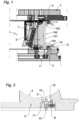
figure 1 is a schematic cross-sectional view of a portion of a vulcanising mould for tyres for vehicle wheels, fitted with an insert produced in accordance with the present invention; -
figure 2 is a schematic view on an enlarged scale of the portion of the mould denoted by II infigure 1 ; -
figure 3 is a schematic sectional view of the insert offigure 2 when decoupled from the mould; -
figure 4 is a plan view from above of the insert offigure 3 ; -
figure 5 is a schematic sectional view on a further enlarged scale of a portion of the insert indicated by V infigure 3 ; -
figure 6 is a schematic view of a portion of a sidewall of a tyre obtained using the mould offigure 1 . - With reference to the accompanying figures, a mould for vulcanising tyres for vehicle wheels produced in accordance with the present invention is denoted overall by 1. The
mould 1 has a conventional overall general structure and comprises a closed moulding chamber in which agreen tyre 100 is received for the moulding and vulcanisation process. - The
tyre 100 has a generally toroidal shape developed around a rotational axis and comprises a tyre structure that is conventional per se, on which an elastomericmaterial tread band 101 is arranged in a radially outer position, on which tread band there is defined a tread surface intended for contact with a road surface, as well as a pair ofsidewalls 102, extended from the ends of the tread surface towards the rotational axis. - With reference to the radial and axial directions of the
tyre 100 when it is received in themould 1, the moulding chamber is delimited radially by a plurality ofheads 2, generally at least 8, which are suitably shaped to form annular sectors and which are intended as a whole to contact thetread band 101, and axially by a pair ofsidewall plates 3, which are substantially intended to contact thetyre sidewalls 102. - Both the
heads 2 andsidewall plates 3 may be moved away from each other to allow the mould to be opened and the green tyre to be inserted into the moulding chamber and removed once it has been moulded and vulcanised. - A
heating device 7 is associated with theheads 2 andsidewall plates 3 to transmit to the green tyre the heat necessary to reach the temperature intended for vulcanisation. - Inside the moulding chamber of the
mould 1, a membrane, which is conventional per se and not shown in the accompanying figures, may be provided and may be expanded to compress thegreen tyre 100 against the inner walls of theheads 2 andsidewall plates 3 at a predetermined pressure. - On the inner walls of the
mould 1 intended to come into contact with the green tyre, corresponding pluralities of raised portions and recesses are suitably formed so as to obtain, by moulding on the radially outer surface of thetread band 101, the configuration of the tread pattern and, on thesidewalls 102, writing and images useful, for example, for providing visible information to the user regarding the characteristics of thetyre 100. - In particular, on at least one
sidewall plate 3, and preferably on bothsidewall plates 3, amoulding surface 4 is defined and is intended to contact the outer surface of atyre sidewall 102. - On the
moulding surface 4 of thesidewall plate 3 there is also provided, in a suitable position, aseat 5 to accommodate, with the option of removal, aninsert 10. - The
insert 10 comprises amain body 11, on which there is defined abase surface 12, turned towards the outside of thesidewall plate 3 when theinsert 10 is received in theseat 5, as well as astem 13 extended from themain body 11, on the opposite side to thebase surface 12. - On the
sidewall plate 3 there is also provided alocking device 8 to engage thestem 13 and hold theinsert 10 firmly engaged in theseat 5. - This locking device may be of the screw type, or snap type, or magnetic type, or it may adopt any other system suitable for holding the
insert 10 inside theseat 5 removably. - Preferably, from the
main body 11 there is also extended, in an eccentric position, a pin (not shown in the figures) intended to be received in a dedicated recess formed inside theseat 5. The engagement of the pin in the corresponding recess is necessary so that theinsert 10 may be fully received in theseat 5 and ensures that theinsert 10 is coupled to theseat 5 only with a predetermined orientation. - Preferably, the
main body 11 has a profile tapered away from thebase surface 12, so as to allow a substantially tight fit with thesidewall plate 3, and so as to prevent, as far as possible, any elastomeric material from entering theseat 5. - As already mentioned, the
base surface 12 is arranged inside the moulding chamber and is intended to contact thetyre sidewall 102. - The coupling of the
insert 10 in theseat 5 is such that thebase surface 12 is substantially continuous with themoulding surface 4 of thesidewall plate 3, without any significant steps at the transition between the two surfaces. - In addition, the
base surface 12 has a curved profile, quite similar to the profile of themoulding surface 4, so as to maintain the continuity of the overall surface trend. Thebase surface 12, seen from above (Figure 4 ), has a generally rectangular form with rounded corners, and on it there are identified anupper edge 14, alower edge 15, connected to each other by a pair of opposite side edges 16. - In the preferred example described herein, the
base surface 12 has a length of approximately 34 mm and a height of approximately 19 mm. - The
upper edge 14 is positioned in theseat 5 in a radially outer position, intended to face the tread surface of thetyre 100, while thelower edge 15 is positioned in theseat 5 in a radially inner position, intended to face the ends (the beads) of thetyre 100. - Preferably, to facilitate the insertion of the
insert 10 into theseat 5 with the correct orientation, theupper edge 14 is connected to the side edges 16 with a first radius of curvature, while thelower edge 15 has a second radius of curvature, smaller than the first radius of curvature. - In particular, the first radius of curvature is about 7 mm, while the second radius of curvature is about 5 mm.
- A substantially square
central area 18, with sides of approximately 15 mm, is defined on the base surface, and in said area there is a QR code produced in the ways described hereinafter, surrounded by a framingarea 19 of approximately 2 mm, which is substantially smooth, and two oppositelateral areas 17, in which information of alphanumerical nature may be provided. - On the
base surface 12, there is formed a plurality ofprojections 20, extended from thebase surface 12 along a direction X substantially perpendicular thereto. - The
projections 20 are substantially identical to one another and have a truncated cone profile defined by alateral surface 21 extended from abase 22, which is part of thebase surface 12, towards apeak 23. - The
lateral surface 21 is inclined at an angle A of approximately 20° to the direction X and has a roughness Ra between approximately 6 to and approximately 7 µm. Eachprojection 20 also has a height H of approximately 0.6 mm and a diameter varying between a value D1 of approximately 0.45 mm at thebase 22 and a value D2 of approximately 0.1 mm at thepeak 23. - The
base surface 12 preferably has a roughness lower than the roughness of thelateral surface 21, for example between 5 and 6 µm. - The
projections 20 are arranged inside thecentral area 18 according to a predetermined configuration, depending on the coded information contained in the QR code (seefigure 4 , for example). In particular, thecentral area 18 is subdivided into basic square areas P with a side length of 0.5 mm, and each of these basic areas P comprises aprojection 20 which, under consideration of the dimensions of thebase 22, occupies the basic area almost fully with a free margin of a few hundredths of a millimetre, or, alternatively, comprises only thebase surface 12. - The
insert 10 is formed in accordance with one of the processes described below. - On the
central body 11, appropriately shaped, there is identified the surface intended to remain turned towards the outside when theinsert 10 is received in theseat 5. This surface is then subjected to a treatment of material removal by laser differently in the various areas, so that in some areas the material is removed uniformly, defining thebase surface 12, this being substantially smooth, while in other areas the processing is carried out by removing the material present around specific portions of the main body, so as to form theprojections 20. - The positioning of the basic areas provided with
projections 20 and of the basic areas formed only by thebase surface 12 is predetermined depending on the QR code to be moulded on thetyre sidewall 102. - In particular, the laser treatment is carried out maintaining the beam substantially perpendicular to the surface being processed and using a power between 20 and 60 KW, a frequency between 100 and 300 KHz and a speed between 800 and 1500 mm/s.
- The laser treatment leaves both the
base surface 12 and thepeak 23 of theprojections 20 with micro grooves, whereas thelateral surface 21 of theprojections 20 has a profile with micro steps, which, at the ends, may be hook-shaped. - Such irregularities of the surfaces define their roughness and, in addition, determine the tendency of the elastomeric compound to adhere thereto.
- At the end of the material-removal step, the roughness of the surfaces and above all the ability of the elastomeric compound to be removed from the insert without tearing is not yet at the desired levels, and therefore the
base surface 12 and itsprojections 20 are subjected to a further treatment which, in a first preferred embodiment, is a sandblasting treatment. - In particular, the sandblasting is conducted by throwing a jet of glass microspheres with dimensions of between 20 and 100 µm, in the absence of water, from a distance of 10 to 50 cm at a pressure of approximately 5-10 bar.
- Following this treatment, the crests of the irregularities of the surfaces are smoothed, and, in particular, any micro hooks and the micro points present on the lateral surfaces 21 of the
projections 20 are rounded. - This makes it possible to sensibly increase the ability of the elastomeric compound to be detached from the mould, thus also increasing the difference in roughness between the
base surface 12 andlateral surface 21. - In particular, after the sandblasting treatment, the
base surface 12 has a roughness between 5 and 6 µm, and thelateral surface 21 has a roughness between 6 and 7 µm. - In a second preferred embodiment, the
base surface 12 and theprojections 20 thereof, at the end of the laser treatment, are subjected to a coating treatment that involves the application of a coating layer. - In a first exemplary embodiment of the coating treatment, the insert may be treated by depositing, on the
base surface 12 and on theprojections 20, a composite material formed by particles based on tetrafluoroethylene and dispersed in a matrix based on a nickel-phosphorus alloy. - In particular, the matrix is an alloy formed by 87%-90% nickel and 10-13% phosphorus and contains from 20% to 30% by volume of tetrafluoroethylene particles less than 1 µm in size.
- In a second exemplary embodiment, the coating layer, which is about 5 - 15 µm thick, is applied to the
base surface 12 and to theprojections 20 by galvanic deposition of metallic chrome. - The
insert 10, once prepared, is positioned in theseat 5 and coupled at thestem 13 by the hookingdevice 8, so as to be firmly held on thesidewall plate 3 and with thebase surface 12 substantially aligned with themoulding surface 4. - The correct positioning of the
seat 5 is favoured by the different curvature of the connections of the upper and lower edges to the lateral edges and by the provision of the pin. - The vulcanising and moulding process of the
tyre 100 is carried out in the usual manner, introducing the green tyre into the moulding chamber, closing themould 1, expanding the internal membrane, and heating the mould. - During this step, the
green tyre sidewall 102 is pressed against themould surface 4 and thebase surface 12 of the insert. In this way, the surface of thesidewall 102 is imprinted with that which is formed in relief on the base surface 12a of the insert. In particular, aQR code 105 is obtained, as in thecentral area 18 of theinsert 10, and is formed by the plurality of recesses corresponding to theprojections 20 and by the substantially smooth surface corresponding to thebase surface 12 between theprojections 20. - Once the vulcanising step is complete, the
mould 1 is opened and the moulded andvulcanised tyre 100 is removed. - Thanks to the features of the present invention, the
QR code 105 is intact, without any portions of the compound torn between the recesses and with an optimal contrast between dark basic areas and light basic areas, such that the QR code may be read easily and accurately by an optical reader.
Claims (13)
- Insert (10) for a mould (1) for vulcanising tyres for vehicle wheels, the insert being arranged to be received in a seat (5) formed on a moulding surface (4) of said mould (1) and comprising a base surface (12) from which a plurality of projections (20) having a substantially circular section extends, each of which comprises a lateral surface (21) extending away from said base surface (12) towards a peak (23) of said projection (20) that is remote from said base surface, wherein said lateral surface (21):- defines a tapered profile of said projection (20) away from said base surface (12),- is inclined of an angle of between 10° and 25° with respect to a direction (X) perpendicular to said base surface (12), and- has a roughness of between 4 and 11 µm;and wherein said base surface (12) has a roughness that is less than the roughness of said lateral surface (21).
- Insert according to claim 1, wherein said projections (20) are substantially identical to one another.
- Insert according to either claim 1 or claim 2, wherein said lateral surface (21) is inclined of an angle of between 15° and 25° with respect to said direction (X) perpendicular to said base surface (12).
- Insert according to any one of the preceding claims, wherein said lateral surface (21) has a roughness of between 5.5 and 8 µm.
- Insert according to any one of the preceding claims, wherein said base surface (12) has a roughness of between 4.5 and 7 µm.
- Insert according to any one of the preceding claims, wherein said projections (20) are raised with respect to said base surface (12) by a height of between 0.5 mm and 0.7 mm.
- Insert according to any one of the preceding claims, wherein said projections (20) have a base (22) which has a diameter (D1) of between 0.40 and 0.49 mm.
- Mould (1) for vulcanising tyres for vehicle wheels, comprising:- at least one sidewall plate (3) on which a moulding surface (4) is defined which is intended for contacting an external surface of a sidewall (102) of a green tyre (100),- a removable insert (10) that is received in a seat (5) formed on said moulding surface (4) and comprises a base surface (12) intended for contacting a portion of said external surface of the sidewall (102) of the green tyre (100), wherein said insert (10) is according to any one of the preceding claims.
- Process for producing an insert according to any one of claims 1 to 7, comprising:- providing a main body (11) of said insert,- removing material from said main body (11) by means of laser so as to form a base surface (12) thereon with respect to which a plurality of projections (20) is raised, each of which comprises a lateral surface (21) extending away from said base surface (12) towards a peak (23) of said projection that is remote from said base surface (12), wherein said lateral surface (21) defines a tapered profile of said projection away from said base surface (12) and is inclined at an angle of between 10° and 25° with respect to a direction (X) perpendicular to said base surface (12),- treating at least said plurality of projections (20) so as to obtain a roughness of said lateral surface (21) of between 4 and 11 µm.
- Process according to claim 9, wherein at least said plurality of projections (20) is subjected to a sandblasting treatment.
- Process according to claim 10, wherein said sandblasting treatment is carried out using glass microspheres which have a diameter of between 20 and 100 µm.
- Process according to claim 9, wherein a coating layer is applied to at least said plurality of projections (20), by means of depositing a composite material formed of polymeric particles dispersed in a metal matrix.
- Process according to claim 12, wherein said deposition is carried out until the coating layer has a thickness of between 5 and 15 µm.
Applications Claiming Priority (2)
| Application Number | Priority Date | Filing Date | Title |
|---|---|---|---|
| IT201900008856 | 2019-06-13 | ||
| PCT/IB2020/055072 WO2020250072A1 (en) | 2019-06-13 | 2020-05-28 | Insert for a mould for vulcanising tyres for vehicle wheels, process for producing said insert and process for vulcanising tyres |
Publications (3)
| Publication Number | Publication Date |
|---|---|
| EP3983215A1 EP3983215A1 (en) | 2022-04-20 |
| EP3983215C0 EP3983215C0 (en) | 2024-11-06 |
| EP3983215B1 true EP3983215B1 (en) | 2024-11-06 |
Family
ID=68138688
Family Applications (1)
| Application Number | Title | Priority Date | Filing Date |
|---|---|---|---|
| EP20742904.4A Active EP3983215B1 (en) | 2019-06-13 | 2020-05-28 | Insert for a mould for vulcanising tyres for vehicle wheels and process for producing said insert |
Country Status (5)
| Country | Link |
|---|---|
| US (2) | US12005662B2 (en) |
| EP (1) | EP3983215B1 (en) |
| CN (1) | CN114269551A (en) |
| MX (1) | MX2021014859A (en) |
| WO (1) | WO2020250072A1 (en) |
Citations (2)
| Publication number | Priority date | Publication date | Assignee | Title |
|---|---|---|---|---|
| US20140166177A1 (en) * | 2011-03-31 | 2014-06-19 | Compagnie Generale Des Establissements Michelin | High contrast tire pattern |
| US20170080656A1 (en) * | 2014-04-30 | 2017-03-23 | Compagnie Generale Des Etablissements Michelin | Mould Element For A Tire Mould Comprising A Mark |
Family Cites Families (14)
| Publication number | Priority date | Publication date | Assignee | Title |
|---|---|---|---|---|
| JP3072921B2 (en) * | 1991-07-04 | 2000-08-07 | 住友ゴム工業株式会社 | Pneumatic tire |
| JP2000142026A (en) | 1998-11-10 | 2000-05-23 | Yokohama Rubber Co Ltd:The | Pneumatic tire, manufacture thereof and metal mold for molding tire |
| ES2216762T3 (en) * | 1999-05-26 | 2004-11-01 | Pirelli Pneumatici S.P.A. | PROCEDURE FOR THE MANUFACTURE OF A TIRE WITH KEYS AND MOLD FOR THE SAME. |
| US8916001B2 (en) | 2006-04-05 | 2014-12-23 | Gvd Corporation | Coated molds and related methods and components |
| JP5356447B2 (en) * | 2011-04-05 | 2013-12-04 | 東洋ゴム工業株式会社 | Tire mold, method for producing pneumatic tire, and pneumatic tire |
| FR2976523B1 (en) | 2011-06-15 | 2014-07-25 | Michelin Soc Tech | PNEUMATIC COMPRISING A HIGH-CONTRAST PATTERN AND PATTERN PROTECTION RIBS |
| JP5314122B2 (en) | 2011-12-28 | 2013-10-16 | 株式会社ブリヂストン | Tire mold, tire, and tire manufacturing method |
| JP6088137B2 (en) | 2011-12-28 | 2017-03-01 | 株式会社ブリヂストン | Tire and tire mold |
| DE102013223567A1 (en) * | 2013-10-24 | 2015-04-30 | Continental Reifen Deutschland Gmbh | Product comprising an opto-electronically readable code |
| EP2905125B1 (en) * | 2014-02-10 | 2017-08-30 | 4JET Technologies GmbH | Digital coding of rubber articles |
| FR3020594B1 (en) * | 2014-04-30 | 2018-01-05 | Compagnie Generale Des Etablissements Michelin | PNEUMATIC COMPRISING A MATRIX SYMBOL WITH HIGH CONTRAST ON THE FLANK |
| FR3024391B1 (en) | 2014-07-30 | 2017-03-03 | Michelin & Cie | MATRIX WITH TEXTURED INSERTS FOR MANUFACTURING A TEXTURE MOLD FOR MOLDING AND VULCANIZING TIRES |
| FR3049902A1 (en) * | 2016-04-08 | 2017-10-13 | Michelin & Cie | PNEUMATIC COMPRISING A MATRIX SYMBOL CODE WITH SPECIAL BRIGHTNESS DIFFERENCE |
| DE102016215732B4 (en) * | 2016-08-23 | 2024-10-10 | Continental Reifen Deutschland Gmbh | Vulcanizing mold for vehicle tires and vehicle tires as such |
-
2020
- 2020-05-28 US US17/596,222 patent/US12005662B2/en active Active
- 2020-05-28 EP EP20742904.4A patent/EP3983215B1/en active Active
- 2020-05-28 MX MX2021014859A patent/MX2021014859A/en unknown
- 2020-05-28 CN CN202080041731.4A patent/CN114269551A/en active Pending
- 2020-05-28 WO PCT/IB2020/055072 patent/WO2020250072A1/en not_active Ceased
-
2024
- 2024-04-08 US US18/629,554 patent/US12257799B2/en active Active
Patent Citations (2)
| Publication number | Priority date | Publication date | Assignee | Title |
|---|---|---|---|---|
| US20140166177A1 (en) * | 2011-03-31 | 2014-06-19 | Compagnie Generale Des Establissements Michelin | High contrast tire pattern |
| US20170080656A1 (en) * | 2014-04-30 | 2017-03-23 | Compagnie Generale Des Etablissements Michelin | Mould Element For A Tire Mould Comprising A Mark |
Also Published As
| Publication number | Publication date |
|---|---|
| MX2021014859A (en) | 2022-02-10 |
| US20220297400A1 (en) | 2022-09-22 |
| WO2020250072A1 (en) | 2020-12-17 |
| BR112021024610A2 (en) | 2022-02-08 |
| US20240293986A1 (en) | 2024-09-05 |
| EP3983215C0 (en) | 2024-11-06 |
| US12257799B2 (en) | 2025-03-25 |
| CN114269551A (en) | 2022-04-01 |
| EP3983215A1 (en) | 2022-04-20 |
| US12005662B2 (en) | 2024-06-11 |
Similar Documents
| Publication | Publication Date | Title |
|---|---|---|
| CN110696563B (en) | Tire with a tire body | |
| CN110382261B (en) | Tire with textured portion on sidewall | |
| EP1254750B1 (en) | Tire mold | |
| CN110520236B (en) | Method and software for laser engraving a mold element of a tire mold | |
| GB2114511A (en) | Decorative ornamentation for a rubber article | |
| US20250010666A1 (en) | Pneumatic tire with a textured surface, method of manufacturing, and textured mold | |
| EP3983215B1 (en) | Insert for a mould for vulcanising tyres for vehicle wheels and process for producing said insert | |
| EP2799250B1 (en) | Tire and tire-forming mold | |
| EP0305617B1 (en) | Tyre vulcanizing mould | |
| EP3983214B1 (en) | Insert for a mould for vulcanising tyres for vehicle wheels | |
| EP1527865B1 (en) | Method of manufacturing laminated mold | |
| EP3941729B1 (en) | Mold segment irregular wear and noise countermeasure | |
| BR112021024610B1 (en) | INSERT FOR A MOLD AND MOLD FOR VULCANIZING TIRES FOR VEHICLE WHEELS, AND PROCESS FOR PRODUCING AN INSERT | |
| JP7279409B2 (en) | pneumatic tire | |
| JP2000006154A (en) | Vulcanization mold for pneumatic tire, manufacture of pneumatic tire, and pneumatic tire | |
| JP3992217B2 (en) | Slick tire | |
| EP3983210B1 (en) | Mould and process for vulcanising tyres for vehicle wheels | |
| JP2004255620A (en) | Tire mold and method for manufacturing pneumatic tire using the same | |
| JP2025115218A (en) | Heavy-duty tires | |
| JP6939305B2 (en) | Tires and tire manufacturing methods | |
| JP2024118688A (en) | Pneumatic tires and vulcanization molds | |
| CN115891240A (en) | Tire vulcanization mold, tire manufacturing method, and tire | |
| JP2025119293A (en) | tire | |
| JPH081672A (en) | Tire mold | |
| JPH11147405A (en) | Precure tread |
Legal Events
| Date | Code | Title | Description |
|---|---|---|---|
| STAA | Information on the status of an ep patent application or granted ep patent |
Free format text: STATUS: UNKNOWN |
|
| STAA | Information on the status of an ep patent application or granted ep patent |
Free format text: STATUS: THE INTERNATIONAL PUBLICATION HAS BEEN MADE |
|
| PUAI | Public reference made under article 153(3) epc to a published international application that has entered the european phase |
Free format text: ORIGINAL CODE: 0009012 |
|
| STAA | Information on the status of an ep patent application or granted ep patent |
Free format text: STATUS: REQUEST FOR EXAMINATION WAS MADE |
|
| 17P | Request for examination filed |
Effective date: 20211122 |
|
| AK | Designated contracting states |
Kind code of ref document: A1 Designated state(s): AL AT BE BG CH CY CZ DE DK EE ES FI FR GB GR HR HU IE IS IT LI LT LU LV MC MK MT NL NO PL PT RO RS SE SI SK SM TR |
|
| DAV | Request for validation of the european patent (deleted) | ||
| DAX | Request for extension of the european patent (deleted) | ||
| STAA | Information on the status of an ep patent application or granted ep patent |
Free format text: STATUS: EXAMINATION IS IN PROGRESS |
|
| 17Q | First examination report despatched |
Effective date: 20231130 |
|
| GRAP | Despatch of communication of intention to grant a patent |
Free format text: ORIGINAL CODE: EPIDOSNIGR1 |
|
| STAA | Information on the status of an ep patent application or granted ep patent |
Free format text: STATUS: GRANT OF PATENT IS INTENDED |
|
| INTG | Intention to grant announced |
Effective date: 20240709 |
|
| GRAS | Grant fee paid |
Free format text: ORIGINAL CODE: EPIDOSNIGR3 |
|
| GRAA | (expected) grant |
Free format text: ORIGINAL CODE: 0009210 |
|
| STAA | Information on the status of an ep patent application or granted ep patent |
Free format text: STATUS: THE PATENT HAS BEEN GRANTED |
|
| AK | Designated contracting states |
Kind code of ref document: B1 Designated state(s): AL AT BE BG CH CY CZ DE DK EE ES FI FR GB GR HR HU IE IS IT LI LT LU LV MC MK MT NL NO PL PT RO RS SE SI SK SM TR |
|
| REG | Reference to a national code |
Ref country code: GB Ref legal event code: FG4D |
|
| REG | Reference to a national code |
Ref country code: CH Ref legal event code: EP |
|
| REG | Reference to a national code |
Ref country code: DE Ref legal event code: R096 Ref document number: 602020040832 Country of ref document: DE |
|
| REG | Reference to a national code |
Ref country code: IE Ref legal event code: FG4D |
|
| U01 | Request for unitary effect filed |
Effective date: 20241106 |
|
| U07 | Unitary effect registered |
Designated state(s): AT BE BG DE DK EE FI FR IT LT LU LV MT NL PT RO SE SI Effective date: 20241113 |
|
| PG25 | Lapsed in a contracting state [announced via postgrant information from national office to epo] |
Ref country code: IS Free format text: LAPSE BECAUSE OF FAILURE TO SUBMIT A TRANSLATION OF THE DESCRIPTION OR TO PAY THE FEE WITHIN THE PRESCRIBED TIME-LIMIT Effective date: 20250306 Ref country code: HR Free format text: LAPSE BECAUSE OF FAILURE TO SUBMIT A TRANSLATION OF THE DESCRIPTION OR TO PAY THE FEE WITHIN THE PRESCRIBED TIME-LIMIT Effective date: 20241106 |
|
| PG25 | Lapsed in a contracting state [announced via postgrant information from national office to epo] |
Ref country code: ES Free format text: LAPSE BECAUSE OF FAILURE TO SUBMIT A TRANSLATION OF THE DESCRIPTION OR TO PAY THE FEE WITHIN THE PRESCRIBED TIME-LIMIT Effective date: 20241106 |
|
| PG25 | Lapsed in a contracting state [announced via postgrant information from national office to epo] |
Ref country code: NO Free format text: LAPSE BECAUSE OF FAILURE TO SUBMIT A TRANSLATION OF THE DESCRIPTION OR TO PAY THE FEE WITHIN THE PRESCRIBED TIME-LIMIT Effective date: 20250206 |
|
| PG25 | Lapsed in a contracting state [announced via postgrant information from national office to epo] |
Ref country code: GR Free format text: LAPSE BECAUSE OF FAILURE TO SUBMIT A TRANSLATION OF THE DESCRIPTION OR TO PAY THE FEE WITHIN THE PRESCRIBED TIME-LIMIT Effective date: 20250207 |
|
| PG25 | Lapsed in a contracting state [announced via postgrant information from national office to epo] |
Ref country code: PL Free format text: LAPSE BECAUSE OF FAILURE TO SUBMIT A TRANSLATION OF THE DESCRIPTION OR TO PAY THE FEE WITHIN THE PRESCRIBED TIME-LIMIT Effective date: 20241106 |
|
| PG25 | Lapsed in a contracting state [announced via postgrant information from national office to epo] |
Ref country code: RS Free format text: LAPSE BECAUSE OF FAILURE TO SUBMIT A TRANSLATION OF THE DESCRIPTION OR TO PAY THE FEE WITHIN THE PRESCRIBED TIME-LIMIT Effective date: 20250206 |
|
| U20 | Renewal fee for the european patent with unitary effect paid |
Year of fee payment: 6 Effective date: 20250527 |
|
| PG25 | Lapsed in a contracting state [announced via postgrant information from national office to epo] |
Ref country code: SM Free format text: LAPSE BECAUSE OF FAILURE TO SUBMIT A TRANSLATION OF THE DESCRIPTION OR TO PAY THE FEE WITHIN THE PRESCRIBED TIME-LIMIT Effective date: 20241106 |
|
| PGFP | Annual fee paid to national office [announced via postgrant information from national office to epo] |
Ref country code: GB Payment date: 20250527 Year of fee payment: 6 |
|
| PG25 | Lapsed in a contracting state [announced via postgrant information from national office to epo] |
Ref country code: SK Free format text: LAPSE BECAUSE OF FAILURE TO SUBMIT A TRANSLATION OF THE DESCRIPTION OR TO PAY THE FEE WITHIN THE PRESCRIBED TIME-LIMIT Effective date: 20241106 |
|
| PG25 | Lapsed in a contracting state [announced via postgrant information from national office to epo] |
Ref country code: CZ Free format text: LAPSE BECAUSE OF FAILURE TO SUBMIT A TRANSLATION OF THE DESCRIPTION OR TO PAY THE FEE WITHIN THE PRESCRIBED TIME-LIMIT Effective date: 20241106 |
|
| PLBE | No opposition filed within time limit |
Free format text: ORIGINAL CODE: 0009261 |
|
| STAA | Information on the status of an ep patent application or granted ep patent |
Free format text: STATUS: NO OPPOSITION FILED WITHIN TIME LIMIT |
|
| 26N | No opposition filed |
Effective date: 20250807 |
|
| REG | Reference to a national code |
Ref country code: CH Ref legal event code: H13 Free format text: ST27 STATUS EVENT CODE: U-0-0-H10-H13 (AS PROVIDED BY THE NATIONAL OFFICE) Effective date: 20251223 |
|
| PG25 | Lapsed in a contracting state [announced via postgrant information from national office to epo] |
Ref country code: CH Free format text: LAPSE BECAUSE OF NON-PAYMENT OF DUE FEES Effective date: 20250531 |
|
| PG25 | Lapsed in a contracting state [announced via postgrant information from national office to epo] |
Ref country code: MC Free format text: LAPSE BECAUSE OF FAILURE TO SUBMIT A TRANSLATION OF THE DESCRIPTION OR TO PAY THE FEE WITHIN THE PRESCRIBED TIME-LIMIT Effective date: 20241106 |
|
| PG25 | Lapsed in a contracting state [announced via postgrant information from national office to epo] |
Ref country code: IE Free format text: LAPSE BECAUSE OF NON-PAYMENT OF DUE FEES Effective date: 20250528 |