EP3983029B1 - Systems and methods for measuring electrical characteristic of medical fluids - Google Patents
Systems and methods for measuring electrical characteristic of medical fluids Download PDFInfo
- Publication number
- EP3983029B1 EP3983029B1 EP20724374.2A EP20724374A EP3983029B1 EP 3983029 B1 EP3983029 B1 EP 3983029B1 EP 20724374 A EP20724374 A EP 20724374A EP 3983029 B1 EP3983029 B1 EP 3983029B1
- Authority
- EP
- European Patent Office
- Prior art keywords
- chamber
- electrodes
- fluid
- inlet
- outlet
- Prior art date
- Legal status (The legal status is an assumption and is not a legal conclusion. Google has not performed a legal analysis and makes no representation as to the accuracy of the status listed.)
- Active
Links
Images



Classifications
-
- A—HUMAN NECESSITIES
- A61—MEDICAL OR VETERINARY SCIENCE; HYGIENE
- A61M—DEVICES FOR INTRODUCING MEDIA INTO, OR ONTO, THE BODY; DEVICES FOR TRANSDUCING BODY MEDIA OR FOR TAKING MEDIA FROM THE BODY; DEVICES FOR PRODUCING OR ENDING SLEEP OR STUPOR
- A61M1/00—Suction or pumping devices for medical purposes; Devices for carrying-off, for treatment of, or for carrying-over, body-liquids; Drainage systems
- A61M1/02—Blood transfusion apparatus
-
- A—HUMAN NECESSITIES
- A61—MEDICAL OR VETERINARY SCIENCE; HYGIENE
- A61M—DEVICES FOR INTRODUCING MEDIA INTO, OR ONTO, THE BODY; DEVICES FOR TRANSDUCING BODY MEDIA OR FOR TAKING MEDIA FROM THE BODY; DEVICES FOR PRODUCING OR ENDING SLEEP OR STUPOR
- A61M1/00—Suction or pumping devices for medical purposes; Devices for carrying-off, for treatment of, or for carrying-over, body-liquids; Drainage systems
- A61M1/14—Dialysis systems; Artificial kidneys; Blood oxygenators ; Reciprocating systems for treatment of body fluids, e.g. single needle systems for hemofiltration or pheresis
- A61M1/15—Dialysis systems; Artificial kidneys; Blood oxygenators ; Reciprocating systems for treatment of body fluids, e.g. single needle systems for hemofiltration or pheresis with a cassette forming partially or totally the flow circuit for the treating fluid, e.g. the dialysate fluid circuit or the treating gas circuit
- A61M1/152—Details related to the interface between cassette and machine
-
- A—HUMAN NECESSITIES
- A61—MEDICAL OR VETERINARY SCIENCE; HYGIENE
- A61M—DEVICES FOR INTRODUCING MEDIA INTO, OR ONTO, THE BODY; DEVICES FOR TRANSDUCING BODY MEDIA OR FOR TAKING MEDIA FROM THE BODY; DEVICES FOR PRODUCING OR ENDING SLEEP OR STUPOR
- A61M1/00—Suction or pumping devices for medical purposes; Devices for carrying-off, for treatment of, or for carrying-over, body-liquids; Drainage systems
- A61M1/14—Dialysis systems; Artificial kidneys; Blood oxygenators ; Reciprocating systems for treatment of body fluids, e.g. single needle systems for hemofiltration or pheresis
- A61M1/15—Dialysis systems; Artificial kidneys; Blood oxygenators ; Reciprocating systems for treatment of body fluids, e.g. single needle systems for hemofiltration or pheresis with a cassette forming partially or totally the flow circuit for the treating fluid, e.g. the dialysate fluid circuit or the treating gas circuit
- A61M1/159—Dialysis systems; Artificial kidneys; Blood oxygenators ; Reciprocating systems for treatment of body fluids, e.g. single needle systems for hemofiltration or pheresis with a cassette forming partially or totally the flow circuit for the treating fluid, e.g. the dialysate fluid circuit or the treating gas circuit specially adapted for peritoneal dialysis
-
- A—HUMAN NECESSITIES
- A61—MEDICAL OR VETERINARY SCIENCE; HYGIENE
- A61M—DEVICES FOR INTRODUCING MEDIA INTO, OR ONTO, THE BODY; DEVICES FOR TRANSDUCING BODY MEDIA OR FOR TAKING MEDIA FROM THE BODY; DEVICES FOR PRODUCING OR ENDING SLEEP OR STUPOR
- A61M1/00—Suction or pumping devices for medical purposes; Devices for carrying-off, for treatment of, or for carrying-over, body-liquids; Drainage systems
- A61M1/14—Dialysis systems; Artificial kidneys; Blood oxygenators ; Reciprocating systems for treatment of body fluids, e.g. single needle systems for hemofiltration or pheresis
- A61M1/16—Dialysis systems; Artificial kidneys; Blood oxygenators ; Reciprocating systems for treatment of body fluids, e.g. single needle systems for hemofiltration or pheresis with membranes
-
- A—HUMAN NECESSITIES
- A61—MEDICAL OR VETERINARY SCIENCE; HYGIENE
- A61M—DEVICES FOR INTRODUCING MEDIA INTO, OR ONTO, THE BODY; DEVICES FOR TRANSDUCING BODY MEDIA OR FOR TAKING MEDIA FROM THE BODY; DEVICES FOR PRODUCING OR ENDING SLEEP OR STUPOR
- A61M1/00—Suction or pumping devices for medical purposes; Devices for carrying-off, for treatment of, or for carrying-over, body-liquids; Drainage systems
- A61M1/14—Dialysis systems; Artificial kidneys; Blood oxygenators ; Reciprocating systems for treatment of body fluids, e.g. single needle systems for hemofiltration or pheresis
- A61M1/28—Peritoneal dialysis ; Other peritoneal treatment, e.g. oxygenation
-
- A—HUMAN NECESSITIES
- A61—MEDICAL OR VETERINARY SCIENCE; HYGIENE
- A61M—DEVICES FOR INTRODUCING MEDIA INTO, OR ONTO, THE BODY; DEVICES FOR TRANSDUCING BODY MEDIA OR FOR TAKING MEDIA FROM THE BODY; DEVICES FOR PRODUCING OR ENDING SLEEP OR STUPOR
- A61M1/00—Suction or pumping devices for medical purposes; Devices for carrying-off, for treatment of, or for carrying-over, body-liquids; Drainage systems
- A61M1/36—Other treatment of blood in a by-pass of the natural circulatory system, e.g. temperature adaptation, irradiation ; Extra-corporeal blood circuits
- A61M1/3607—Regulation parameters
- A61M1/3609—Physical characteristics of the blood, e.g. haematocrit, urea
-
- A—HUMAN NECESSITIES
- A61—MEDICAL OR VETERINARY SCIENCE; HYGIENE
- A61M—DEVICES FOR INTRODUCING MEDIA INTO, OR ONTO, THE BODY; DEVICES FOR TRANSDUCING BODY MEDIA OR FOR TAKING MEDIA FROM THE BODY; DEVICES FOR PRODUCING OR ENDING SLEEP OR STUPOR
- A61M1/00—Suction or pumping devices for medical purposes; Devices for carrying-off, for treatment of, or for carrying-over, body-liquids; Drainage systems
- A61M1/36—Other treatment of blood in a by-pass of the natural circulatory system, e.g. temperature adaptation, irradiation ; Extra-corporeal blood circuits
- A61M1/3621—Extra-corporeal blood circuits
- A61M1/3626—Gas bubble detectors
-
- A—HUMAN NECESSITIES
- A61—MEDICAL OR VETERINARY SCIENCE; HYGIENE
- A61M—DEVICES FOR INTRODUCING MEDIA INTO, OR ONTO, THE BODY; DEVICES FOR TRANSDUCING BODY MEDIA OR FOR TAKING MEDIA FROM THE BODY; DEVICES FOR PRODUCING OR ENDING SLEEP OR STUPOR
- A61M1/00—Suction or pumping devices for medical purposes; Devices for carrying-off, for treatment of, or for carrying-over, body-liquids; Drainage systems
- A61M1/36—Other treatment of blood in a by-pass of the natural circulatory system, e.g. temperature adaptation, irradiation ; Extra-corporeal blood circuits
- A61M1/3621—Extra-corporeal blood circuits
- A61M1/3669—Electrical impedance measurement of body fluids; transducers specially adapted therefor
-
- G—PHYSICS
- G01—MEASURING; TESTING
- G01N—INVESTIGATING OR ANALYSING MATERIALS BY DETERMINING THEIR CHEMICAL OR PHYSICAL PROPERTIES
- G01N27/00—Investigating or analysing materials by the use of electric, electrochemical, or magnetic means
- G01N27/02—Investigating or analysing materials by the use of electric, electrochemical, or magnetic means by investigating impedance
- G01N27/04—Investigating or analysing materials by the use of electric, electrochemical, or magnetic means by investigating impedance by investigating resistance
- G01N27/06—Investigating or analysing materials by the use of electric, electrochemical, or magnetic means by investigating impedance by investigating resistance of a liquid
- G01N27/07—Construction of measuring vessels; Electrodes therefor
-
- G—PHYSICS
- G01—MEASURING; TESTING
- G01N—INVESTIGATING OR ANALYSING MATERIALS BY DETERMINING THEIR CHEMICAL OR PHYSICAL PROPERTIES
- G01N27/00—Investigating or analysing materials by the use of electric, electrochemical, or magnetic means
- G01N27/02—Investigating or analysing materials by the use of electric, electrochemical, or magnetic means by investigating impedance
- G01N27/04—Investigating or analysing materials by the use of electric, electrochemical, or magnetic means by investigating impedance by investigating resistance
- G01N27/06—Investigating or analysing materials by the use of electric, electrochemical, or magnetic means by investigating impedance by investigating resistance of a liquid
- G01N27/08—Investigating or analysing materials by the use of electric, electrochemical, or magnetic means by investigating impedance by investigating resistance of a liquid which is flowing continuously
-
- G—PHYSICS
- G01—MEASURING; TESTING
- G01N—INVESTIGATING OR ANALYSING MATERIALS BY DETERMINING THEIR CHEMICAL OR PHYSICAL PROPERTIES
- G01N33/00—Investigating or analysing materials by specific methods not covered by groups G01N1/00 - G01N31/00
- G01N33/48—Biological material, e.g. blood, urine; Haemocytometers
- G01N33/483—Physical analysis of biological material
- G01N33/487—Physical analysis of biological material of liquid biological material
- G01N33/49—Blood
-
- A—HUMAN NECESSITIES
- A61—MEDICAL OR VETERINARY SCIENCE; HYGIENE
- A61M—DEVICES FOR INTRODUCING MEDIA INTO, OR ONTO, THE BODY; DEVICES FOR TRANSDUCING BODY MEDIA OR FOR TAKING MEDIA FROM THE BODY; DEVICES FOR PRODUCING OR ENDING SLEEP OR STUPOR
- A61M1/00—Suction or pumping devices for medical purposes; Devices for carrying-off, for treatment of, or for carrying-over, body-liquids; Drainage systems
- A61M1/14—Dialysis systems; Artificial kidneys; Blood oxygenators ; Reciprocating systems for treatment of body fluids, e.g. single needle systems for hemofiltration or pheresis
- A61M1/15—Dialysis systems; Artificial kidneys; Blood oxygenators ; Reciprocating systems for treatment of body fluids, e.g. single needle systems for hemofiltration or pheresis with a cassette forming partially or totally the flow circuit for the treating fluid, e.g. the dialysate fluid circuit or the treating gas circuit
- A61M1/156—Constructional details of the cassette, e.g. specific details on material or shape
- A61M1/1562—Details of incorporated reservoirs
-
- A—HUMAN NECESSITIES
- A61—MEDICAL OR VETERINARY SCIENCE; HYGIENE
- A61M—DEVICES FOR INTRODUCING MEDIA INTO, OR ONTO, THE BODY; DEVICES FOR TRANSDUCING BODY MEDIA OR FOR TAKING MEDIA FROM THE BODY; DEVICES FOR PRODUCING OR ENDING SLEEP OR STUPOR
- A61M2205/00—General characteristics of the apparatus
- A61M2205/12—General characteristics of the apparatus with interchangeable cassettes forming partially or totally the fluid circuit
-
- A—HUMAN NECESSITIES
- A61—MEDICAL OR VETERINARY SCIENCE; HYGIENE
- A61M—DEVICES FOR INTRODUCING MEDIA INTO, OR ONTO, THE BODY; DEVICES FOR TRANSDUCING BODY MEDIA OR FOR TAKING MEDIA FROM THE BODY; DEVICES FOR PRODUCING OR ENDING SLEEP OR STUPOR
- A61M2205/00—General characteristics of the apparatus
- A61M2205/33—Controlling, regulating or measuring
- A61M2205/3317—Electromagnetic, inductive or dielectric measuring means
-
- A—HUMAN NECESSITIES
- A61—MEDICAL OR VETERINARY SCIENCE; HYGIENE
- A61M—DEVICES FOR INTRODUCING MEDIA INTO, OR ONTO, THE BODY; DEVICES FOR TRANSDUCING BODY MEDIA OR FOR TAKING MEDIA FROM THE BODY; DEVICES FOR PRODUCING OR ENDING SLEEP OR STUPOR
- A61M2205/00—General characteristics of the apparatus
- A61M2205/33—Controlling, regulating or measuring
- A61M2205/3327—Measuring
-
- A—HUMAN NECESSITIES
- A61—MEDICAL OR VETERINARY SCIENCE; HYGIENE
- A61M—DEVICES FOR INTRODUCING MEDIA INTO, OR ONTO, THE BODY; DEVICES FOR TRANSDUCING BODY MEDIA OR FOR TAKING MEDIA FROM THE BODY; DEVICES FOR PRODUCING OR ENDING SLEEP OR STUPOR
- A61M2205/00—General characteristics of the apparatus
- A61M2205/50—General characteristics of the apparatus with microprocessors or computers
- A61M2205/502—User interfaces, e.g. screens or keyboards
- A61M2205/505—Touch-screens; Virtual keyboard or keypads; Virtual buttons; Soft keys; Mouse touches
-
- A—HUMAN NECESSITIES
- A61—MEDICAL OR VETERINARY SCIENCE; HYGIENE
- A61M—DEVICES FOR INTRODUCING MEDIA INTO, OR ONTO, THE BODY; DEVICES FOR TRANSDUCING BODY MEDIA OR FOR TAKING MEDIA FROM THE BODY; DEVICES FOR PRODUCING OR ENDING SLEEP OR STUPOR
- A61M2205/00—General characteristics of the apparatus
- A61M2205/50—General characteristics of the apparatus with microprocessors or computers
- A61M2205/52—General characteristics of the apparatus with microprocessors or computers with memories providing a history of measured variating parameters of apparatus or patient
Definitions
- This invention relates to measuring conductivity of a medical fluid.
- impurities and toxins are removed from the blood of a patient by drawing the blood out of the patient through a blood access site, typically via a catheter, and then passing the blood through an artificial kidney (often referred to as a "dialyzer").
- the artificial kidney includes a semi-permeable membrane that separates a first conduit from a second conduit.
- a dialysis solution (often referred to as a "dialysate”) flows through the first conduit of the dialyzer while the patient's blood flows through the second conduit of the dialyzer, causing impurities and toxins to be transferred from the blood to the dialysate through the semi-permeable membrane.
- the impurities and toxins can, for example, be removed from the blood by a diffusion process. After passing through the dialyzer, the purified blood is then returned to the patient.
- Maintaining a substantially constant concentration of sodium in the patient's blood throughout the hemodialysis treatment can help to reduce or prevent discomfort experienced by the patient. Therefore, sodium concentrations in the patient's blood and in the dialysate can be monitored during hemodialysis treatment.
- US 2017/0182235 describes an electrical sensor for sensing electromagnetic properties of process fluids in a dialysis machine or a similar medical device can include a probe for interfacing with the fluids that is made from electronic fabric materials.
- the electronic fabric probe can include one or more conductors embedded in a non-conductive fabric layer.
- the electronic fabric probe is accommodated an enclosure which establishes a flow path with respect to the probe to establish fluid contact between the process fluids and the conductors.
- the conductors can apply or sense current and/or voltage with respect to the fluid.
- a portion of the electronic fabric probe can be disposed externally of the enclosure to provide electronic communication externally of the enclosure.
- US 2006/0275907 describes device for measuring the pressure of a medium.
- the device includes a measuring chamber through which the medium can flow and which has at least one elastically deformable wall, at least one wall that is more rigid by comparison to said first wall, and an inlet and outlet for the medium.
- At least one excitation electrode is provided in or on the at least one more rigid wall of the measuring chamber, and at least one signal electrode is provided on the elastically deformable wall for impedance measurement.
- US 2017/0216512 describes a method of flushing a dialyzer with a flushing liquid, wherein the dialyzer is arranged in a dialysate-side circuit of a blood treatment device and wherein the dialyzer has at least one dialysate-side chamber which has at least one inlet and at least one outlet for the flushing liquid and which is flowed through by the flushing liquid, wherein at least one property of the flushing liquid is measured at the outlet of the dialyzer or downstream of the dialyzer in the dialysate-side circuit to obtain one or more outlet-side measured values, wherein the property depends on the quantity of the air in the flushing liquid.
- Implementations of the present disclosure are directed to a disposable device for measuring electrical characteristics of medical fluids, such as blood in dialysis systems.
- the device has a configuration that directs bubbles in the fluid away from electrodes that measure the electrical characteristics of the fluid.
- Implementations of the present disclosure provide one or more of the following technical advantages and/or technical improvements over previously available solutions.
- the implementations allow monitoring fluid parameters (e.g., concentration, fluid elements, etc.) of a medical fluid by measuring electrical characteristics of the fluid.
- a dialysate should have a conductivity that indicates that a certain amount and ratio of sodium bicarbonate is present, because an imbalance could impact the health of the patient and cause discomfort.
- the present implementations provide a contactless sensor that can measure conductivity of the dialysate without making direct contact (e.g., via electrodes) with the patient's body.
- the implementations include a pre-calibrated and disposable data collecting cell that collects data of the fluid's electrical characteristics (e.g., electrical voltage).
- the pre-calibrated cell eliminates a need to calibrate the cell for each use, which makes it easier for an unsophisticated patient to use the cell at home and without assistance of a medical staff. For example, a patient may insert or attach the cell to a dialysis system to monitor their blood parameters and adjust the dialysis system accordingly without being concerned about calibrating the cell before use.
- the cell can be very light weighted and substantially small, which makes it easy to carry, store, and use.
- the cell is designed to improve accuracy in measuring the fluid's electrical characteristics by directing gas (e.g., air) bubbles away from the cell's electrodes.
- Implementations of the present disclosure provide a device that can be used to measure one or more electrical characteristics (e.g., electrical conductivity) of fluids such as blood in dialysis systems.
- the device has a disposable data collecting cell that can be replaced after a certain number of uses, for example, after every use.
- the cell includes a chamber with an inlet and an outlet. Fluid enters the chamber through the inlet and flows out of the chamber through the outlet. Multiple electrodes are located within the chamber to measure electrical characteristics of the fluid.
- the chamber is designed to direct bubbles within the fluid away from the electrodes.
- moving along the length of the chamber from the inlet to the outlet, a distance between an upper surface and a lower surface of the chamber varies so that the bubbles would be directed from the lower distance region to the higher distance region.
- the electrodes can be located at the lower distance region of the chamber.
- the upper surface of the chamber can be in concave shape and the electrodes can be located away from edges of the concaved upper surface to which the bubbles are directed.
- FIG. 1 depicts an example application of the implementations of the present disclosure.
- a system 100 is connected to a patient 102.
- the system 100 can include a dialysis system (e.g., a peritoneal dialysis machine) to dialyze the patient's blood.
- the system 100 includes a data collecting unit 104, and a measurement unit 106.
- Patient's blood flows from the patient 102's body to the data collecting unit 104 through a first conduit 108, and flows back from the data collecting unit 104 to the patient's body through a second conduit 110. During this process, the data collecting unit 104 collects data of the patient's blood. Data collected by the data collecting unit 104 is transferred to the measurement unit 106 through the communication channel 112.
- the communication channel can be a wired and/or a wireless channel.
- the measurement unit 106 includes one or more devices to measure electrical characteristic(s) of the blood based on the data received from the data collecting unit 104.
- the measurement unit 106 can include an impedance analyzer to measure impedance or conductivity of the blood.
- the measurement unit 106 can also include one or more power supplies that generate an electrical current, which is transmitted through the communication channel 112 to the data collecting unit 104 to excite the blood.
- the heater tray 216 is sized and shaped to accommodate a bag of PD solution such as dialysate (e.g., a 5 liter bag of dialysate).
- the PD machine 202 also includes a user interface such as a touch screen display 218 and additional control buttons 220 that can be operated by a user (e.g., a caregiver or a patient) to allow, for example, set up, initiation, and/or termination of a PD treatment.
- Dialysate bags 222 are suspended from fingers on the sides of the cart 204, and a heater bag 224 is positioned in the heater tray 216.
- the dialysate bags 222 and the heater bag 224 are connected to the cassette 212 via dialysate bag lines 226 and a heater bag line 228, respectively.
- the dialysate bag lines 226 can be used to pass dialysate from dialysate bags 222 to the cassette 212 during use, and the heater bag line 228 can be used to pass dialysate back and forth between the cassette 212 and the heater bag 224 during use.
- a patient line 230 and a drain line 232 are connected to the cassette 212.
- the patient line 230 can be connected to a patient's abdomen via a catheter and can be used to pass dialysate back and forth between the cassette 212 and the patient's peritoneal cavity during use.
- the catheter may be connected to the patient line 230 via a port such as a fitting.
- the drain line 232 can be connected to a drain or drain receptacle and can be used to pass dialysate from the cassette 212 to the drain or drain receptacle during use.
- the PD machine 202 also includes a control unit 239 (e.g., a processor).
- the control unit 239 can receive signals from and transmit signals to the touch screen display 218, the control panel 220, and the various other components of the PD system 200.
- the control unit 239 can control the operating parameters of the PD machine 102.
- the control unit 239 is an MPC823 PowerPC device manufactured by Motorola, Inc.
- the data collecting unit 104 includes a data collecting cell that has multiple electrodes to electrically excite the blood and to measure electrical voltage within the blood.
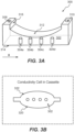
- FIG. 3A illustrates a perspective view of an example data collecting cell 300.
- the cell 300 includes a chamber 302 with an inlet 308 and an outlet 310.
- Fluid e.g., blood, medical fluids
- Fluid enters the chamber 302 through the inlet 308 and flows out of the chamber through the outlet 310.
- Multiple electrodes 304a, 304b, 304c, and 304d are located within the chamber to measure electrical parameters (such as electrical voltage) of the fluid in response to applying an electrical current to the fluid.
- the chamber 302 contains multiple electrodes 304a, 304b, 304c, and 304d. Two or more electrodes are used to apply electrical current to the fluid, and two or more electrodes are used to measure electrical voltage.
- electrodes 304a and 304d can be connected to a power supply of the measurement unit 106, and electrodes 304b and 304c can be connected to a measuring device, such as an impedance analyzer, in the measurement unit 106.
- the same electrodes that apply current can also measure voltage.
- the chamber 302 has an upper surface 312 and a lower surface 314. Moving along the length of the chamber from the inlet 308 to the outlet 310 (in direction x), the distance between the upper surface 312 and the lower surface 314 varies. In the illustrated example, the distance between the upper and the lower surfaces is greater at about the inlet and the outlet regions of the chamber than at the region where the electrodes are located. Such configuration directs the gas bubbles (e.g., air bubbles) in the fluid away from the electrodes and towards the outlet (or towards the inlet depending on the fluid flow's speed).
- gas bubbles e.g., air bubbles
- the upper surface of the chamber has a concave shape, and the distance between the upper and the lower surfaces is minimum at a region halfway between the inlet and the outlet.
- the minimum distance can be at any part of the cell.
- the minimum distance may be in the first half of the chamber along direction x (i.e., closer to the inlet than to the outlet) or in the second half of the chamber along direction x (i.e., closer to the outlet than to the inlet).
- the illustrated upper surface 312 of the example cell 300 is curved.
- the upper surface can be designed as a set of multiple inclined plates.
- the upper surface can include two diverging plates that intersect at a common line at a region between the inlet and outlet (along direction x), forming a V-shape upper surface.
- An upper surface of a cell can have a combination of curved and plate surfaces.
- FIG. 3B illustrates a bottom view of the cell 300 that depicts a bottom profile of the side walls 320 and 322.
- the side walls 320 and 322 of the chamber are curved.
- the chamber 302 can have an elliptical cross section. Curved side walls help in reducing turbulent fluid flow and provide a laminar fluid flow through the chamber.
- the example cell 300 includes four electrodes, however, cells with more or less number of electrodes (e.g., two or three electrodes) can also be designed.
- a cell can be designed to have only two electrodes, where the same electrodes apply the electrical current and measure the voltage of the two electrodes. Additional electrodes (e.g., four) can improve measurement accuracy as separate set of electrodes can be used for applying current and measuring voltage. Relatively fewer electrodes (e.g., two) can help in reducing the size of the cell.
- the cell 302 can provide an excitation electrical current to the fluid.
- the electrical current can have a frequency ranging from DC to 100kHz.
- the excitation current can be in any bipolar or unipolar AC form such as sinusoidal, sawtooth, square wave shape, etc.
- each cell can be designed for a specific cell constant.
- the calibration can stay accurate for a predetermined number of use, and the cell can be disposed afterwards.
- a cell may be calibrated for 13.8 millisiemens (mS) and may be set for one time use.
- the calibration may be set for a specific temperature, e.g., 37 Celsius, and/or a specific type of fluid (e.g., blood, urine, saline, etc.).
- a cell constant (that is used to calibrate a cell) is a measurement of the fluid volume contained between the two measuring electrodes, for example, electrodes 304b and 304c that measure the electrical voltage.
- a data collecting cell may be designed for a particular cell constant. Parameters of the measurement unit 106 to which the data collecting cell is to be attached, may determine the particular cell constant. For example, the data collecting cell can be designed to have a cell constant between 12-16 millisiemens (mS), for example, 14 mS.
- a cell constant of a data collecting cell depends on the geometry of and the distance between two measuring electrodes of the cell.
- the electrodes can have any shape. However, electrodes with curved cross section (e.g., cylindrical electrodes similar to the electrodes depicted in FIGs. 3A and 3B ) are preferred to electrodes that have one or more corners (e.g., cubic or pyramid shaped electrodes) because curvature reduces fluid turbulence in the chamber as compared to edges.
- At least the measuring electrodes that measure electrical voltage should be completely immersed/sunk in the fluid.
- An exposure of a conductive portion of a measuring electrode to air can lead to inaccuracy in measuring electrical characteristics of the fluid.
- a data collecting cell can include a gas detector sensor that alerts an exposure of one or more electrodes to air (or to other gasses within the chamber, or to vacuum).
- FIG. 5 illustrates an example data collecting cell 500 including a gas detector sensor 502 within the cell's chamber.
- the gas detector sensor 502 includes multiple sensor electrodes 502a and 502b. Each sensor electrode is an insulated conductors and has a respective conductive portion. The conductive portions are configured to transmit an electrical current when sunk in a fluid. However, no current is transmitted between the conductive portions of the two sensor electrodes when the conductive portions are exposed to a gaseous environment such as air. Accordingly, when no current is transmitted between the sensor electrodes, the sensor 502 detects that the fluid level is too low and at least one of the measuring electrodes is exposed to air.
- the conductive portions of the sensor electrodes 502a and 502b are at their respective tips 504.
- At least one of the two sensor electrodes 502a and 502b can be designed to be taller than at least one of the measuring electrodes (e.g., the measuring electrode 506) of the cell 500 in order to detect situations when the measuring electrode (or a portion of it) is exposed to air. For example, in the tilted position illustrated in FIG. 5 , the fluid level is dropped below the measuring electrode 506's height, causing a portion of the measuring sensor 506 to stick out of the fluid and be exposed to air.
- the sensor electrodes are taller than any of the excitation electrodes (i.e., electrodes that apply the excitation electrical current) or measuring electrodes (i.e., electrodes that measure electrical voltage,) of the cell.
- two or more sensor electrodes are assigned to particular excitation or measuring electrode(s).
- the electrodes 502a and 502b may be set to detect exposure of electrode 406 to air, irrespective of whether or not any other electrode is sunk in the fluid or exposed to air.
- the system 100 can also include a pump configured to pressurize the fluid inside the data collecting cell 300 of the data collecting unit 104.
- the pump (not shown) can be attached to the data collecting unit 104, or either of the first or the second conduits 108, 110.
- the pump can be a peristaltic pump that applies pressure pulses to the fluid. Such pulses force gas bubbles that are attached to any part of the data collecting cell (e.g., the electrodes, the side walls, or the lower or upper surfaces of the chamber,) to be detached and be moved towards the outlet.
- peristaltic pumps is particularly helpful in removing smaller bubbles that may be harder to remove, especially in a constant or low-speed fluid current.
- the cell's size and weight are substantially small, which provide convenient handling and carrying by a single person.
- the device can have dimensions smaller than 5cm x 5cm x 5 cm (e.g., 1cm x 3cm x 3cm), and can be made of plastic.
- FIG. 6 depicts an example process 600 that can be executed in accordance with the implementations of the present disclosure.
- the process 600 can be implemented by system 100 (e.g., the PD system 200) including the data collecting cell 300, or by any other system capable of performing the process 600.
- fluid is received through an inlet of a chamber and flows about multiple electrodes located within the chamber (602).
- fluid can be received at the chamber 302 through the inlet 308.
- the fluid passes through the chamber and about the electrodes 304a through 304d.
- the electrodes can be connected to a measurement unit, a power supply, and/or a dialysis machine.
- An electrical current is applied to a first set of electrodes within the chamber (604).
- the electrodes 304a and 304d may transmit electrical current through the fluid within the chamber.
- the electrodes 304a and 304d are connected to a power supply, for example, located in the measurement unit 106.
- Electrode 304b and 304c can measure the electrical voltage upon the application of an electrical current to the fluid.
- the second set of electrodes can be the same or different from the first set of electrodes. Having the two sets separate would improve measurement accuracy but would also increase the chamber size needed for setting the electrodes.
- Fluid can be pumped out of the chamber through an outlet of the chamber (608).
- pressure pulses can be applied to the fluid to pump the fluid out of the chamber. Such pressure pulses help in removing small bubbles from the fluid.
- Conductivity (or any other desired electrical characteristics) of the fluid is measured (or calculated) based on the applied electrical current and the measured electrical voltage (610).
- the electrodes that measured the electrical voltage can transmit their measured data to a measurement unit (e.g., an impedance analyzer) to calculate the conductivity of the current.
- the chamber is designed so that bubbles within the fluid are directed away from the electrodes.
- the chamber can have a lower surface, and an upper surface separated from the lower surface.
- the lower surface is parallel to a portion of the upper surfaces in which the inlet and outlet are formed. Moving along a length of the chamber from the inlet to the outlet, a distance between the upper surface and the lower surface changes in at least one dimension of the chamber (e.g., in a direction perpendicular to the lower surface).
- the upper surface can be similar to the upper surface 312 in FIG. 3A .
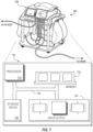
- FIG. 7 is a block diagram of an example computer system 700 that can be used as part of the system 100 of FIG. 1 , for example to perform the measurements or analysis of the measurement unit 106.
- the system 700 includes a processor 710, a memory 720, a storage device 730, and an input/output device 740.
- Each of the components 710, 720, 730, and 740 can be interconnected, for example, using a system bus 750.
- the processor 710 is capable of processing instructions for execution within the system 700.
- the processor 710 can be a single-threaded processor, a multi-threaded processor, or a quantum computer.
- the processor 710 is capable of processing instructions stored in the memory 720 or on the storage device 730.
- the processor 710 may execute operations such as causing the dialysis system to carry out dialysis functions.
- the memory 720 stores information within the system 700.
- the memory 720 is a computer-readable medium.
- the memory 720 can, for example, be a volatile memory unit or a non-volatile memory unit.
- the memory 720 stores information for causing the pumps of the dialysis system to operate as described herein.
- the storage device 730 is capable of providing mass storage for the system 700.
- the storage device 730 is a non-transitory computer-readable medium.
- the storage device 730 can include, for example, a hard disk device, an optical disk device, a solid-date drive, a flash drive, magnetic tape, or some other large capacity storage device.
- the storage device 730 may alternatively be a cloud storage device, e.g., a logical storage device including multiple physical storage devices distributed on a network and accessed using a network.
- the input/output device 740 provides input/output operations for the system 700.
- the input/output device 740 includes one or more of network interface devices (e.g., an Ethernet card), a serial communication device (e.g., an RS-232 10 port), and/or a wireless interface device (e.g., an 802.11 card, a 3G wireless modem, or a 4G wireless modem).
- the input/output device 740 may include short-range wireless transmission and receiving components, such as Wi-Fi, Bluetooth, and/or near field communication (NFC) components, among others.
- NFC near field communication
- the input/output device includes driver devices configured to receive input data and send output data to other input/output devices, e.g., keyboard, printer and display devices (such as the touch screen display 118).
- driver devices configured to receive input data and send output data to other input/output devices, e.g., keyboard, printer and display devices (such as the touch screen display 118).
- mobile computing devices, mobile communication devices, and other devices are used.
- the system 700 is a microcontroller.
- a microcontroller is a device that contains multiple elements of a computer system in a single electronics package.
- the single electronics package could contain the processor 710, the memory 720, the storage device 730, and input/output devices 740.
- the measurement unit and/or the data collection unit described herein can be part of any medical system, such as dialysis systems (e.g., a hemodialysis system), a heart lung machine, a chemotherapy system, or any other system that introduces fluid into body.
- dialysis systems e.g., a hemodialysis system
- a heart lung machine e.g., a heart lung machine
- a chemotherapy system e.g., a chemotherapy system
- the data collecting unit in general, and the data collecting cell, in particular, can be used for determining electrical characteristics of any other type of fluids, or any medical fluids such as plasma, saline, or urine, to name a few.
Landscapes
- Health & Medical Sciences (AREA)
- Heart & Thoracic Surgery (AREA)
- Life Sciences & Earth Sciences (AREA)
- Engineering & Computer Science (AREA)
- General Health & Medical Sciences (AREA)
- Urology & Nephrology (AREA)
- Biomedical Technology (AREA)
- Vascular Medicine (AREA)
- Hematology (AREA)
- Public Health (AREA)
- Veterinary Medicine (AREA)
- Animal Behavior & Ethology (AREA)
- Anesthesiology (AREA)
- Emergency Medicine (AREA)
- Chemical & Material Sciences (AREA)
- Physics & Mathematics (AREA)
- Analytical Chemistry (AREA)
- Biochemistry (AREA)
- General Physics & Mathematics (AREA)
- Pathology (AREA)
- Immunology (AREA)
- Electrochemistry (AREA)
- Chemical Kinetics & Catalysis (AREA)
- Cardiology (AREA)
- Ecology (AREA)
- Molecular Biology (AREA)
- Food Science & Technology (AREA)
- Medicinal Chemistry (AREA)
- Biophysics (AREA)
- External Artificial Organs (AREA)
Description
- This invention relates to measuring conductivity of a medical fluid.
- During hemodialysis, impurities and toxins are removed from the blood of a patient by drawing the blood out of the patient through a blood access site, typically via a catheter, and then passing the blood through an artificial kidney (often referred to as a "dialyzer"). The artificial kidney includes a semi-permeable membrane that separates a first conduit from a second conduit. Generally, a dialysis solution (often referred to as a "dialysate") flows through the first conduit of the dialyzer while the patient's blood flows through the second conduit of the dialyzer, causing impurities and toxins to be transferred from the blood to the dialysate through the semi-permeable membrane. The impurities and toxins can, for example, be removed from the blood by a diffusion process. After passing through the dialyzer, the purified blood is then returned to the patient.
- Maintaining a substantially constant concentration of sodium in the patient's blood throughout the hemodialysis treatment can help to reduce or prevent discomfort experienced by the patient. Therefore, sodium concentrations in the patient's blood and in the dialysate can be monitored during hemodialysis treatment.
-
US 2017/0182235 describes an electrical sensor for sensing electromagnetic properties of process fluids in a dialysis machine or a similar medical device can include a probe for interfacing with the fluids that is made from electronic fabric materials. The electronic fabric probe can include one or more conductors embedded in a non-conductive fabric layer. The electronic fabric probe is accommodated an enclosure which establishes a flow path with respect to the probe to establish fluid contact between the process fluids and the conductors. The conductors can apply or sense current and/or voltage with respect to the fluid. A portion of the electronic fabric probe can be disposed externally of the enclosure to provide electronic communication externally of the enclosure. -
US 2006/0275907 describes device for measuring the pressure of a medium. The device includes a measuring chamber through which the medium can flow and which has at least one elastically deformable wall, at least one wall that is more rigid by comparison to said first wall, and an inlet and outlet for the medium. At least one excitation electrode is provided in or on the at least one more rigid wall of the measuring chamber, and at least one signal electrode is provided on the elastically deformable wall for impedance measurement. -
US 3,365,659 describes a flow-through conductivity cell. -
US 2017/0216512 describes a method of flushing a dialyzer with a flushing liquid, wherein the dialyzer is arranged in a dialysate-side circuit of a blood treatment device and wherein the dialyzer has at least one dialysate-side chamber which has at least one inlet and at least one outlet for the flushing liquid and which is flowed through by the flushing liquid, wherein at least one property of the flushing liquid is measured at the outlet of the dialyzer or downstream of the dialyzer in the dialysate-side circuit to obtain one or more outlet-side measured values, wherein the property depends on the quantity of the air in the flushing liquid. - According to the invention, a device and method for measuring conductivity of a fluid is provided as defined in the appended claims.
- Implementations of the present disclosure are directed to a disposable device for measuring electrical characteristics of medical fluids, such as blood in dialysis systems. The device has a configuration that directs bubbles in the fluid away from electrodes that measure the electrical characteristics of the fluid.
- Implementations of the present disclosure provide one or more of the following technical advantages and/or technical improvements over previously available solutions. The implementations allow monitoring fluid parameters (e.g., concentration, fluid elements, etc.) of a medical fluid by measuring electrical characteristics of the fluid. For example, a dialysate should have a conductivity that indicates that a certain amount and ratio of sodium bicarbonate is present, because an imbalance could impact the health of the patient and cause discomfort. The present implementations provide a contactless sensor that can measure conductivity of the dialysate without making direct contact (e.g., via electrodes) with the patient's body.
- The implementations include a pre-calibrated and disposable data collecting cell that collects data of the fluid's electrical characteristics (e.g., electrical voltage). The pre-calibrated cell eliminates a need to calibrate the cell for each use, which makes it easier for an unsophisticated patient to use the cell at home and without assistance of a medical staff. For example, a patient may insert or attach the cell to a dialysis system to monitor their blood parameters and adjust the dialysis system accordingly without being worried about calibrating the cell before use. In addition, the cell can be very light weighted and substantially small, which makes it easy to carry, store, and use. Further, the cell is designed to improve accuracy in measuring the fluid's electrical characteristics by directing gas (e.g., air) bubbles away from the cell's electrodes.
- The details of one or more implementations of the present disclosure are set forth in the accompanying drawings and the description below. Other features and advantages of the present disclosure will be apparent from the description and drawings, and from the claims.
-
-
FIG. 1 depicts an example application of the implementations of the present disclosure. -
FIG. 2 illustrates an example of a peritoneal dialysis (PD) system. -
FIG. 3A illustrates a perspective views an example data collecting cell according to implementations of the present disclosure. -
FIG. 3B illustrates a bottom view of the data collecting cell ofFIG. 3A . -
FIG. 4 illustrates fluid flow in an example data collecting cell according to implementations of the present disclosure. -
FIG. 5 illustrates an example data collecting cell including a gas detector sensor according to implementations of the present disclosure. -
FIG. 6 depicts an example process that can be executed in accordance with the implementations of the present disclosure. -
FIG. 7 shows an example of a computer system and related components. - Like reference symbols in the various drawings indicate like elements.
- Implementations of the present disclosure provide a device that can be used to measure one or more electrical characteristics (e.g., electrical conductivity) of fluids such as blood in dialysis systems. The device has a disposable data collecting cell that can be replaced after a certain number of uses, for example, after every use. The cell includes a chamber with an inlet and an outlet. Fluid enters the chamber through the inlet and flows out of the chamber through the outlet. Multiple electrodes are located within the chamber to measure electrical characteristics of the fluid.
- The chamber is designed to direct bubbles within the fluid away from the electrodes. In some implementations, moving along the length of the chamber from the inlet to the outlet, a distance between an upper surface and a lower surface of the chamber varies so that the bubbles would be directed from the lower distance region to the higher distance region. The electrodes can be located at the lower distance region of the chamber. For example, the upper surface of the chamber can be in concave shape and the electrodes can be located away from edges of the concaved upper surface to which the bubbles are directed.
-
FIG. 1 depicts an example application of the implementations of the present disclosure. As depicted, asystem 100 is connected to apatient 102. Thesystem 100 can include a dialysis system (e.g., a peritoneal dialysis machine) to dialyze the patient's blood. Thesystem 100 includes adata collecting unit 104, and ameasurement unit 106. - Patient's blood flows from the
patient 102's body to thedata collecting unit 104 through afirst conduit 108, and flows back from thedata collecting unit 104 to the patient's body through asecond conduit 110. During this process, thedata collecting unit 104 collects data of the patient's blood. Data collected by thedata collecting unit 104 is transferred to themeasurement unit 106 through thecommunication channel 112. The communication channel can be a wired and/or a wireless channel. - The
measurement unit 106 includes one or more devices to measure electrical characteristic(s) of the blood based on the data received from thedata collecting unit 104. For example, themeasurement unit 106 can include an impedance analyzer to measure impedance or conductivity of the blood. Themeasurement unit 106 can also include one or more power supplies that generate an electrical current, which is transmitted through thecommunication channel 112 to thedata collecting unit 104 to excite the blood. -
FIG. 2 shows an example of thesystem 100 ofFIG. 1 . In particular,FIG. 2 shows an exampleperitoneal dialysis system 200 that can may include thedata collecting unit 104 and themeasurement unit 106 described above. Theperitoneal dialysis system 200 includes a PD machine (also generally referred to as a PD cycler) 202 seated on acart 204. ThePD machine 202 includes ahousing 206, adoor 208, and a cassette interface 210 that contacts a disposable PD cassette 212 when the cassette 212 is disposed within a cassette compartment 214 formed between the cassette interface 210 and theclosed door 208. Aheater tray 216 is positioned on top of thehousing 206. Theheater tray 216 is sized and shaped to accommodate a bag of PD solution such as dialysate (e.g., a 5 liter bag of dialysate). ThePD machine 202 also includes a user interface such as atouch screen display 218 andadditional control buttons 220 that can be operated by a user (e.g., a caregiver or a patient) to allow, for example, set up, initiation, and/or termination of a PD treatment. -
Dialysate bags 222 are suspended from fingers on the sides of thecart 204, and aheater bag 224 is positioned in theheater tray 216. Thedialysate bags 222 and theheater bag 224 are connected to the cassette 212 viadialysate bag lines 226 and aheater bag line 228, respectively. Thedialysate bag lines 226 can be used to pass dialysate fromdialysate bags 222 to the cassette 212 during use, and theheater bag line 228 can be used to pass dialysate back and forth between the cassette 212 and theheater bag 224 during use. In addition, apatient line 230 and adrain line 232 are connected to the cassette 212. Thepatient line 230 can be connected to a patient's abdomen via a catheter and can be used to pass dialysate back and forth between the cassette 212 and the patient's peritoneal cavity during use. The catheter may be connected to thepatient line 230 via a port such as a fitting. Thedrain line 232 can be connected to a drain or drain receptacle and can be used to pass dialysate from the cassette 212 to the drain or drain receptacle during use. - The
PD machine 202 also includes a control unit 239 (e.g., a processor). Thecontrol unit 239 can receive signals from and transmit signals to thetouch screen display 218, thecontrol panel 220, and the various other components of thePD system 200. Thecontrol unit 239 can control the operating parameters of thePD machine 102. In some implementations, thecontrol unit 239 is an MPC823 PowerPC device manufactured by Motorola, Inc. - Referring back to
FIG. 1 , thedata collecting unit 104 includes a data collecting cell that has multiple electrodes to electrically excite the blood and to measure electrical voltage within the blood.FIG. 3A illustrates a perspective view of an exampledata collecting cell 300. Thecell 300 includes achamber 302 with aninlet 308 and anoutlet 310. Fluid (e.g., blood, medical fluids) enters thechamber 302 through theinlet 308 and flows out of the chamber through theoutlet 310.Multiple electrodes - The
chamber 302 containsmultiple electrodes electrodes measurement unit 106, andelectrodes measurement unit 106. Alternatively, the same electrodes that apply current can also measure voltage. - The
chamber 302 has anupper surface 312 and alower surface 314. Moving along the length of the chamber from theinlet 308 to the outlet 310 (in direction x), the distance between theupper surface 312 and thelower surface 314 varies. In the illustrated example, the distance between the upper and the lower surfaces is greater at about the inlet and the outlet regions of the chamber than at the region where the electrodes are located. Such configuration directs the gas bubbles (e.g., air bubbles) in the fluid away from the electrodes and towards the outlet (or towards the inlet depending on the fluid flow's speed). - In the
example cell 300, the upper surface of the chamber has a concave shape, and the distance between the upper and the lower surfaces is minimum at a region halfway between the inlet and the outlet. However, the minimum distance can be at any part of the cell. For example, the minimum distance may be in the first half of the chamber along direction x (i.e., closer to the inlet than to the outlet) or in the second half of the chamber along direction x (i.e., closer to the outlet than to the inlet). - In the
example cell 300, the distance between the upper and the lower surfaces is greatest close to the inlet and the outlet regions of the chamber. In other embodiments, the greatest distance may be at any part of the chamber, e.g., other than where the electrodes are located. In other words, the upper surface 212 is not at its greatest distance from the lower surface 214 directly above the electrodes (but does not have to be at its minimum distance directly above the electrodes, either). - The illustrated
upper surface 312 of theexample cell 300 is curved. Alternatively, the upper surface can be designed as a set of multiple inclined plates. For example, the upper surface can include two diverging plates that intersect at a common line at a region between the inlet and outlet (along direction x), forming a V-shape upper surface. An upper surface of a cell can have a combination of curved and plate surfaces. - The illustrated upper surface 212 in
FIG. 3A is connected to the inlet and the outlet byrespective connector walls 316. Alternatively, one or both of the connector walls can be eliminated so that the inlet and/or the outlet is formed on a portion of theupper surface 312. - The
upper surface 312 is connected to thebottom surface 314 through side walls of the chamber (now shown in FIG. 23A).FIG. 3B illustrates a bottom view of thecell 300 that depicts a bottom profile of theside walls side walls chamber 302 can have an elliptical cross section. Curved side walls help in reducing turbulent fluid flow and provide a laminar fluid flow through the chamber. -
FIG. 4 illustrates fluid flow in anelliptical chamber 402. As illustrated, since thechamber 402 does not have any corners, the fluid does not get trapped in any particular part of the chamber, and rather flows smoothly throughout the chamber. - Referring back to
FIG. 3A , theexample cell 300 includes four electrodes, however, cells with more or less number of electrodes (e.g., two or three electrodes) can also be designed. For example, a cell can be designed to have only two electrodes, where the same electrodes apply the electrical current and measure the voltage of the two electrodes. Additional electrodes (e.g., four) can improve measurement accuracy as separate set of electrodes can be used for applying current and measuring voltage. Relatively fewer electrodes (e.g., two) can help in reducing the size of the cell. - Once connected to the power supply, the
cell 302 can provide an excitation electrical current to the fluid. The electrical current can have a frequency ranging from DC to 100kHz. The excitation current can be in any bipolar or unipolar AC form such as sinusoidal, sawtooth, square wave shape, etc. - The excitation current that is being applied to the electrodes can be limited to a predetermined threshold. The threshold can be below 50 milliAmpere (mA), e.g., 10 mA. Limiting the current to a low threshold value guaranty safety in handling the device. Further, a chance of electrical shortening or damages by the exposed electrode contacts can be reduced by limiting the current that can pass through the circuitry that transmits current from the power supply to the cell. For example, the circuitry can have bidirectional diodes that limit the maximum voltage across different sections of the circuit to a threshold voltage, e.g., 1 volt.
- As noted above, the data collecting cell is disposable and can be detached from system 100 (e.g., a dialysis system, such as the
PD system 200 ofFIG. 2 ) after a certain number of uses (e.g., one-time use). The each cell can be pre-calibrated during the manufacturing process before being provided to consumers. This feature provides a consumer-friendly feature that allows patients to replace the cell after a certain number of use without being worried about recalibrating the cell before each use. - To eliminate a need to calibrate the data collection cell for each use, each cell can be designed for a specific cell constant. The calibration can stay accurate for a predetermined number of use, and the cell can be disposed afterwards. For example, a cell may be calibrated for 13.8 millisiemens (mS) and may be set for one time use. The calibration may be set for a specific temperature, e.g., 37 Celsius, and/or a specific type of fluid (e.g., blood, urine, saline, etc.).
- A cell constant (that is used to calibrate a cell) is a measurement of the fluid volume contained between the two measuring electrodes, for example,
electrodes measurement unit 106 to which the data collecting cell is to be attached, may determine the particular cell constant. For example, the data collecting cell can be designed to have a cell constant between 12-16 millisiemens (mS), for example, 14 mS. - A cell constant of a data collecting cell depends on the geometry of and the distance between two measuring electrodes of the cell. The electrodes can have any shape. However, electrodes with curved cross section (e.g., cylindrical electrodes similar to the electrodes depicted in
FIGs. 3A and 3B ) are preferred to electrodes that have one or more corners (e.g., cubic or pyramid shaped electrodes) because curvature reduces fluid turbulence in the chamber as compared to edges. - Electrical conductivity of a fluid in a cell can be calculated based on the cell constant of the cell using the following formula:

- In order to get an accurate measurement of the fluid's electrical characteristics, at least the measuring electrodes that measure electrical voltage (or at least the conductive portion of the measuring electrodes) should be completely immersed/sunk in the fluid. An exposure of a conductive portion of a measuring electrode to air can lead to inaccuracy in measuring electrical characteristics of the fluid.
- A data collecting cell can include a gas detector sensor that alerts an exposure of one or more electrodes to air (or to other gasses within the chamber, or to vacuum).
FIG. 5 illustrates an exampledata collecting cell 500 including agas detector sensor 502 within the cell's chamber. Thegas detector sensor 502 includesmultiple sensor electrodes sensor 502 detects that the fluid level is too low and at least one of the measuring electrodes is exposed to air. - In the example
data collecting cell 500, the conductive portions of thesensor electrodes respective tips 504. At least one of the twosensor electrodes cell 500 in order to detect situations when the measuring electrode (or a portion of it) is exposed to air. For example, in the tilted position illustrated inFIG. 5 , the fluid level is dropped below the measuringelectrode 506's height, causing a portion of the measuringsensor 506 to stick out of the fluid and be exposed to air. - In some embodiments, the sensor electrodes are taller than any of the excitation electrodes (i.e., electrodes that apply the excitation electrical current) or measuring electrodes (i.e., electrodes that measure electrical voltage,) of the cell. In some embodiments, two or more sensor electrodes are assigned to particular excitation or measuring electrode(s). For example, the
electrodes - Referring back to
FIGs. 1 and3A , thesystem 100 can also include a pump configured to pressurize the fluid inside thedata collecting cell 300 of thedata collecting unit 104. The pump (not shown) can be attached to thedata collecting unit 104, or either of the first or thesecond conduits - The cell's size and weight are substantially small, which provide convenient handling and carrying by a single person. For example, the device can have dimensions smaller than 5cm x 5cm x 5 cm (e.g., 1cm x 3cm x 3cm), and can be made of plastic.
-
FIG. 6 depicts anexample process 600 that can be executed in accordance with the implementations of the present disclosure. Theprocess 600 can be implemented by system 100 (e.g., the PD system 200) including thedata collecting cell 300, or by any other system capable of performing theprocess 600. - In this process, fluid is received through an inlet of a chamber and flows about multiple electrodes located within the chamber (602). For example, fluid can be received at the
chamber 302 through theinlet 308. The fluid passes through the chamber and about theelectrodes 304a through 304d. The electrodes can be connected to a measurement unit, a power supply, and/or a dialysis machine. - An electrical current is applied to a first set of electrodes within the chamber (604). For example, the
electrodes electrodes measurement unit 106. - Electrical voltage is measured between a second set of electrodes within the chamber (606). For example, the
electrodes - Fluid can be pumped out of the chamber through an outlet of the chamber (608). For example, pressure pulses can be applied to the fluid to pump the fluid out of the chamber. Such pressure pulses help in removing small bubbles from the fluid.
- Conductivity (or any other desired electrical characteristics) of the fluid is measured (or calculated) based on the applied electrical current and the measured electrical voltage (610). For example, the electrodes that measured the electrical voltage can transmit their measured data to a measurement unit (e.g., an impedance analyzer) to calculate the conductivity of the current.
- The chamber is designed so that bubbles within the fluid are directed away from the electrodes. For example, the chamber can have a lower surface, and an upper surface separated from the lower surface. In some implementations, the lower surface is parallel to a portion of the upper surfaces in which the inlet and outlet are formed. Moving along a length of the chamber from the inlet to the outlet, a distance between the upper surface and the lower surface changes in at least one dimension of the chamber (e.g., in a direction perpendicular to the lower surface). The upper surface can be similar to the
upper surface 312 inFIG. 3A . -
FIG. 7 is a block diagram of anexample computer system 700 that can be used as part of thesystem 100 ofFIG. 1 , for example to perform the measurements or analysis of themeasurement unit 106. For example, a control unit, a computing device, and/or a microcontroller could be examples of thesystem 700 described here. Thesystem 700 includes aprocessor 710, amemory 720, astorage device 730, and an input/output device 740. Each of thecomponents system bus 750. Theprocessor 710 is capable of processing instructions for execution within thesystem 700. Theprocessor 710 can be a single-threaded processor, a multi-threaded processor, or a quantum computer. Theprocessor 710 is capable of processing instructions stored in thememory 720 or on thestorage device 730. Theprocessor 710 may execute operations such as causing the dialysis system to carry out dialysis functions. - The
memory 720 stores information within thesystem 700. In some implementations, thememory 720 is a computer-readable medium. Thememory 720 can, for example, be a volatile memory unit or a non-volatile memory unit. In some implementations, thememory 720 stores information for causing the pumps of the dialysis system to operate as described herein. - The
storage device 730 is capable of providing mass storage for thesystem 700. In some implementations, thestorage device 730 is a non-transitory computer-readable medium. Thestorage device 730 can include, for example, a hard disk device, an optical disk device, a solid-date drive, a flash drive, magnetic tape, or some other large capacity storage device. Thestorage device 730 may alternatively be a cloud storage device, e.g., a logical storage device including multiple physical storage devices distributed on a network and accessed using a network. - The input/
output device 740 provides input/output operations for thesystem 700. In some implementations, the input/output device 740 includes one or more of network interface devices (e.g., an Ethernet card), a serial communication device (e.g., an RS-232 10 port), and/or a wireless interface device (e.g., an 802.11 card, a 3G wireless modem, or a 4G wireless modem). In some implementations, the input/output device 740 may include short-range wireless transmission and receiving components, such as Wi-Fi, Bluetooth, and/or near field communication (NFC) components, among others. In some implementations, the input/output device includes driver devices configured to receive input data and send output data to other input/output devices, e.g., keyboard, printer and display devices (such as the touch screen display 118). In some implementations, mobile computing devices, mobile communication devices, and other devices are used. - In some implementations, the
system 700 is a microcontroller. A microcontroller is a device that contains multiple elements of a computer system in a single electronics package. For example, the single electronics package could contain theprocessor 710, thememory 720, thestorage device 730, and input/output devices 740. - The measurement unit and/or the data collection unit described herein can be part of any medical system, such as dialysis systems (e.g., a hemodialysis system), a heart lung machine, a chemotherapy system, or any other system that introduces fluid into body.
- While blood was used herein as an example fluid for describing the functionality of the embodiments, the data collecting unit, in general, and the data collecting cell, in particular, can be used for determining electrical characteristics of any other type of fluids, or any medical fluids such as plasma, saline, or urine, to name a few.
- A number of embodiments of the invention have been described. Nevertheless, it will be understood that various modifications may be made without departing from the scope of the invention. Accordingly, other embodiments are within the scope of the following claims.
Claims (14)
- A device for measuring conductivity of a fluid, the device comprising:a chamber (300) that includes:an inlet (308),an outlet (310), wherein the fluid enters the chamber through the inlet and flows out of the chamber through the outlet,an upper surface (312), anda lower surface (314) that runs separate from the upper surface; andtwo electrodes (304) located within the chamber and configured to measure electrical voltage in the fluid that enters the chamber through the inlet and flows out of the chamber through the outlet,characterized in that,moving along a length of the chamber from the inlet to the outlet or from the outlet to the inlet, a distance between the upper surface and the lower surface changes in at least one dimension of the chamber such that bubbles in the fluid are directed from a lower distance region to a higher distance region away from the electrodes and towards the outlet or inlet, wherein a greatest distance between the upper surface and the lower surface is in a part of the chamber other than where the electrodes are located.
- The device of claim 1, further comprising an air detector sensor configured to detect that at least one of the two electrodes is exposed to air.
- The device of claim 2, wherein the air detector sensor comprises at least two sensor electrodes (502), each sensor electrode including having a respective conductive tip (504) configured to receive or transmit an electrical current when sunk in a non-gaseous environment.
- The device of any of the preceding claims, wherein the upper surface is in a concave shape and the electrodes are located away from edges of the concaved upper surface.
- The device of any of claims 1 to 3, wherein the upper surface is a set of multiple inclined plates.
- The device of any of the preceding claims, wherein the chamber has a curved side wall (322) that connects the upper surface to the lower surface, and optionally wherein the side wall forms an elliptical cross section for the chamber.
- The device of any of the preceding claims, further comprising two additional electrodes (304), wherein the two electrodes measure the electrical voltage when the two additional electrodes apply the electrical current to the fluid.
- The device of any of the preceding claims, wherein the inlet is connected to a peristaltic pump configured to pump the fluid into the chamber.
- The device of any of the preceding claims, wherein the length of the chamber is less than 5 centimeters.
- The device of any of the preceding claims, wherein the device is configured to be attached to a dialysis system (100, 200), for example, wherein the chamber is formed in a cassette (212) that is insertable into the dialysis system.
- A method of measuring conductivity of a fluid, the method comprising:receiving, through an inlet of the chamber of a device according to any one of claims 1 to 10, the fluid, wherein the fluid flows within the chamber and about multiple electrodes located in the chamber;applying an electrical current to first two electrodes of the multiple electrodes;measuring an electrical voltage between second two electrodes of the multiple electrodes; andmeasuring electrical conductivity of the fluid based on the applied electrical current and the measured electrical voltage,wherein the chamber is designed so that bubbles within the fluid are directed away from the electrodes.
- The method of claim 11, further comprising pumping the fluid out of the chamber by applying pressure pulses to the fluid.
- The method of any of claims 11 and 12, further comprising detecting, by at least two air detector sensors, that at least a tip of at least one electrode is exposed to air, and
optionally wherein each of the air detector sensors has a height that is equal or larger than a height of the at least one electrode, the heights being measured in a direction perpendicular to a bottom surface of the chamber. - The method of any of claims 11 through 13, wherein the fluid comprises a medical fluid or blood.
Applications Claiming Priority (2)
| Application Number | Priority Date | Filing Date | Title |
|---|---|---|---|
| US201962860046P | 2019-06-11 | 2019-06-11 | |
| PCT/US2020/029153 WO2020251659A1 (en) | 2019-06-11 | 2020-04-21 | Systems and methods for measuring electrical characteristic of medical fluids |
Publications (2)
| Publication Number | Publication Date |
|---|---|
| EP3983029A1 EP3983029A1 (en) | 2022-04-20 |
| EP3983029B1 true EP3983029B1 (en) | 2024-12-18 |
Family
ID=70554286
Family Applications (1)
| Application Number | Title | Priority Date | Filing Date |
|---|---|---|---|
| EP20724374.2A Active EP3983029B1 (en) | 2019-06-11 | 2020-04-21 | Systems and methods for measuring electrical characteristic of medical fluids |
Country Status (6)
| Country | Link |
|---|---|
| US (2) | US11879860B2 (en) |
| EP (1) | EP3983029B1 (en) |
| CN (1) | CN114126679A (en) |
| AU (1) | AU2020290351B2 (en) |
| CA (1) | CA3142793A1 (en) |
| WO (1) | WO2020251659A1 (en) |
Families Citing this family (4)
| Publication number | Priority date | Publication date | Assignee | Title |
|---|---|---|---|---|
| EP3781934A1 (en) * | 2018-04-18 | 2021-02-24 | Universiteit Twente | System and method for measuring conductivity |
| CA3142793A1 (en) * | 2019-06-11 | 2020-12-17 | Fresenius Medical Care Holdings, Inc. | Systems and methods for measuring electrical characteristic of medical fluids |
| US11329843B1 (en) * | 2020-08-28 | 2022-05-10 | Earthsystems Technologies, Inc. | Method for multichannel acquisition of geophysical data and system implementation |
| CA3206491A1 (en) * | 2021-01-11 | 2022-07-14 | Fresenius Medical Care Holdings, Inc. | Systems and methods for measuring electrical characteristic of medical fluids |
Family Cites Families (33)
| Publication number | Priority date | Publication date | Assignee | Title |
|---|---|---|---|---|
| DE1160095B (en) | 1962-01-31 | 1963-12-27 | Bayer Ag | Conductivity measuring cell for degassing liquids |
| US3965414A (en) | 1974-02-13 | 1976-06-22 | Teass Jr Horace A | Temperature compensated conductivity measuring system |
| GB1517697A (en) | 1974-08-02 | 1978-07-12 | Kent Ltd G | Measuring cells for measuring electrical conductivity of liquids |
| FR2464477A1 (en) * | 1979-08-28 | 1981-03-06 | Fresenius Chem Pharm Ind | METHOD AND DEVICE FOR THE CONTINUOUS ANALYSIS OF A LIQUID OR GAS IN CIRCULATION |
| US4808930A (en) | 1986-09-03 | 1989-02-28 | Beckman Industrial Corporation | Technique of compensating for capacitive effects in conductivity measurements |
| US4808931A (en) | 1987-04-13 | 1989-02-28 | General Technology, Inc. | Conductivity probe |
| JPH0718902B2 (en) | 1988-10-19 | 1995-03-06 | 株式会社日立製作所 | Electrical conductivity detector |
| AU677001B2 (en) | 1992-03-10 | 1997-04-10 | Christopher Barnes | Apparatus for determining the physical and/or chemical properties of a sample, particularly of blood |
| US5583432A (en) | 1994-04-11 | 1996-12-10 | Sci-Nostics Limited | Electrical method and apparatus for non-contact determination of physical and/or chemical properties of a sample, particularly of blood |
| US5708363A (en) | 1995-10-16 | 1998-01-13 | Signet Scientific Company | Liquid conductivity measurement system using a variable-frequency AC voltage |
| WO2000027199A1 (en) * | 1998-11-12 | 2000-05-18 | Eli Lilly And Company | Aminobenzisoxazole compounds and libraries thereof |
| AU3230201A (en) | 2000-02-23 | 2001-09-03 | Organo Corporation | Multiple electric conductivity measuring apparatus |
| US7029916B2 (en) | 2001-02-21 | 2006-04-18 | Maxcyte, Inc. | Apparatus and method for flow electroporation of biological samples |
| US20040254513A1 (en) | 2002-04-10 | 2004-12-16 | Sherwin Shang | Conductive polymer materials and applications thereof including monitoring and providing effective therapy |
| DE10321099A1 (en) | 2003-05-09 | 2004-11-25 | Cgs Sensortechnik Gmbh | Pressure measuring device |
| US7301388B2 (en) | 2004-12-22 | 2007-11-27 | Mosel Vitelic Corporation | Charge pump with ensured pumping capability |
| US20060275917A1 (en) | 2005-06-02 | 2006-12-07 | The Lab. Of Bio-Informatics Technology | Method for staining and destaining gel, electrophoresis destaining device for gel, and kit for staining and destaining gel |
| US20070024287A1 (en) | 2005-08-01 | 2007-02-01 | Mesa Laboratories, Inc. | Apparatus and method for measuring liquid conductivity and electrode series capacitance |
| KR100991620B1 (en) * | 2008-06-13 | 2010-11-04 | 경희대학교 산학협력단 | Ischemic animal model real time monitoring system |
| IT1390930B1 (en) | 2008-07-11 | 2011-10-27 | Sorin Group Italia Srl | CIRCUIT FOR EXTRACORPAL DIALYSIS WITH PERFECT TYPE CASSETTE |
| JP5097657B2 (en) * | 2008-09-17 | 2012-12-12 | アークレイ株式会社 | Analysis method |
| AU2012258687C1 (en) | 2011-05-24 | 2018-03-08 | Deka Products Limited Partnership | Hemodial ysis system |
| EP2804640B1 (en) * | 2012-01-19 | 2016-01-13 | Baxter International Inc | Method and composition for removing uremic toxins in dialysis processes |
| US9023555B2 (en) * | 2012-02-24 | 2015-05-05 | Alan Devoe | Method of making a fuel cell device |
| CN203923708U (en) * | 2014-06-13 | 2014-11-05 | 广东溢达纺织有限公司 | The liquid circulating apparatus detecting for pH value |
| DE102014014535A1 (en) | 2014-09-30 | 2016-03-31 | Fresenius Medical Care Deutschland Gmbh | Method for rinsing a dialyzer |
| RU2597067C1 (en) * | 2015-05-20 | 2016-09-10 | Михаил Михайлович РУМЯНЦЕВ | Device for measurement and indication of limiting level of liquid oils, liquefied natural gas in opaque reservoirs |
| US10406269B2 (en) * | 2015-12-29 | 2019-09-10 | Fresenius Medical Care Holdings, Inc. | Electrical sensor for fluids |
| US20170173262A1 (en) | 2017-03-01 | 2017-06-22 | François Paul VELTZ | Medical systems, devices and methods |
| FR3064418A1 (en) | 2017-03-27 | 2018-09-28 | Stmicroelectronics (Tours) Sas | OVERVOLTAGE PROTECTION DEVICE |
| CN107860799B (en) * | 2017-12-07 | 2024-01-12 | 杭州泽沃贸易有限公司 | TDS detection device and water purification kettle |
| CA3142793A1 (en) * | 2019-06-11 | 2020-12-17 | Fresenius Medical Care Holdings, Inc. | Systems and methods for measuring electrical characteristic of medical fluids |
| CA3206491A1 (en) | 2021-01-11 | 2022-07-14 | Fresenius Medical Care Holdings, Inc. | Systems and methods for measuring electrical characteristic of medical fluids |
-
2020
- 2020-04-21 CA CA3142793A patent/CA3142793A1/en active Pending
- 2020-04-21 AU AU2020290351A patent/AU2020290351B2/en active Active
- 2020-04-21 CN CN202080042861.XA patent/CN114126679A/en active Pending
- 2020-04-21 WO PCT/US2020/029153 patent/WO2020251659A1/en not_active Ceased
- 2020-04-21 EP EP20724374.2A patent/EP3983029B1/en active Active
- 2020-04-21 US US16/854,745 patent/US11879860B2/en active Active
-
2023
- 2023-11-02 US US18/500,755 patent/US12276628B2/en active Active
Also Published As
| Publication number | Publication date |
|---|---|
| WO2020251659A1 (en) | 2020-12-17 |
| AU2020290351B2 (en) | 2025-04-10 |
| US20200393395A1 (en) | 2020-12-17 |
| US12276628B2 (en) | 2025-04-15 |
| US11879860B2 (en) | 2024-01-23 |
| AU2020290351A1 (en) | 2022-02-03 |
| US20240060924A1 (en) | 2024-02-22 |
| CA3142793A1 (en) | 2020-12-17 |
| CN114126679A (en) | 2022-03-01 |
| EP3983029A1 (en) | 2022-04-20 |
Similar Documents
| Publication | Publication Date | Title |
|---|---|---|
| US12276628B2 (en) | Systems and methods for measuring electrical characteristic of medical fluids | |
| US8040493B2 (en) | Thermal flow meter | |
| EP2445408B1 (en) | Urine measuring device | |
| KR102782554B1 (en) | A peritoneal dialysis system having sensors and configured to diagnose peritonitis | |
| CA2456357C (en) | A method and machine for taking biological fluid to which a solution is added in accordance with a desired ratio | |
| US20130049974A1 (en) | Early detection of low bicarbonate level | |
| EP2760503A1 (en) | Intravenous flow rate controller | |
| JP2005537840A (en) | Control device and control method for blood treatment facility | |
| JP2021531128A5 (en) | ||
| EP3302604A1 (en) | Sensor calibration for dialysis systems | |
| US5416027A (en) | Process and apparatus for monitoring the progress of hemodialysis | |
| JP2013022310A (en) | Blood impedance measuring apparatus, artificial dialyzer and method for measuring blood impedance | |
| KR20170135368A (en) | Method of blood glucose measurement by using Non-invasive blood glucose meter with momentum measurement function | |
| US20240358905A1 (en) | Systems and methods for measuring electrical characteristic of medical fluids | |
| CA3159683A1 (en) | Peritoneal dialysis systems, devices, and methods | |
| WO2023196580A1 (en) | Systems and methods of monitoring a catheter or shunt device and fluid of the system | |
| HK40092568A (en) | Systems and methods for measuring electrical characteristic of medical fluids |
Legal Events
| Date | Code | Title | Description |
|---|---|---|---|
| STAA | Information on the status of an ep patent application or granted ep patent |
Free format text: STATUS: UNKNOWN |
|
| STAA | Information on the status of an ep patent application or granted ep patent |
Free format text: STATUS: THE INTERNATIONAL PUBLICATION HAS BEEN MADE |
|
| PUAI | Public reference made under article 153(3) epc to a published international application that has entered the european phase |
Free format text: ORIGINAL CODE: 0009012 |
|
| STAA | Information on the status of an ep patent application or granted ep patent |
Free format text: STATUS: REQUEST FOR EXAMINATION WAS MADE |
|
| 17P | Request for examination filed |
Effective date: 20220104 |
|
| AK | Designated contracting states |
Kind code of ref document: A1 Designated state(s): AL AT BE BG CH CY CZ DE DK EE ES FI FR GB GR HR HU IE IS IT LI LT LU LV MC MK MT NL NO PL PT RO RS SE SI SK SM TR |
|
| DAV | Request for validation of the european patent (deleted) | ||
| DAX | Request for extension of the european patent (deleted) | ||
| GRAP | Despatch of communication of intention to grant a patent |
Free format text: ORIGINAL CODE: EPIDOSNIGR1 |
|
| STAA | Information on the status of an ep patent application or granted ep patent |
Free format text: STATUS: GRANT OF PATENT IS INTENDED |
|
| INTG | Intention to grant announced |
Effective date: 20240909 |
|
| RIN1 | Information on inventor provided before grant (corrected) |
Inventor name: BARRETT, SPENCER Inventor name: HOOVER, MARY Inventor name: JENSEN, LYNN E. Inventor name: MOSS, JON F. Inventor name: JAMES, PHILIP SCOTT |
|
| GRAS | Grant fee paid |
Free format text: ORIGINAL CODE: EPIDOSNIGR3 |
|
| GRAA | (expected) grant |
Free format text: ORIGINAL CODE: 0009210 |
|
| STAA | Information on the status of an ep patent application or granted ep patent |
Free format text: STATUS: THE PATENT HAS BEEN GRANTED |
|
| AK | Designated contracting states |
Kind code of ref document: B1 Designated state(s): AL AT BE BG CH CY CZ DE DK EE ES FI FR GB GR HR HU IE IS IT LI LT LU LV MC MK MT NL NO PL PT RO RS SE SI SK SM TR |
|
| REG | Reference to a national code |
Ref country code: CH Ref legal event code: EP |
|
| P01 | Opt-out of the competence of the unified patent court (upc) registered |
Free format text: CASE NUMBER: APP_62134/2024 Effective date: 20241121 |
|
| REG | Reference to a national code |
Ref country code: DE Ref legal event code: R096 Ref document number: 602020043329 Country of ref document: DE |
|
| REG | Reference to a national code |
Ref country code: IE Ref legal event code: FG4D |
|
| REG | Reference to a national code |
Ref country code: LT Ref legal event code: MG9D |
|
| PG25 | Lapsed in a contracting state [announced via postgrant information from national office to epo] |
Ref country code: HR Free format text: LAPSE BECAUSE OF FAILURE TO SUBMIT A TRANSLATION OF THE DESCRIPTION OR TO PAY THE FEE WITHIN THE PRESCRIBED TIME-LIMIT Effective date: 20241218 |
|
| PG25 | Lapsed in a contracting state [announced via postgrant information from national office to epo] |
Ref country code: FI Free format text: LAPSE BECAUSE OF FAILURE TO SUBMIT A TRANSLATION OF THE DESCRIPTION OR TO PAY THE FEE WITHIN THE PRESCRIBED TIME-LIMIT Effective date: 20241218 |
|
| PG25 | Lapsed in a contracting state [announced via postgrant information from national office to epo] |
Ref country code: BG Free format text: LAPSE BECAUSE OF FAILURE TO SUBMIT A TRANSLATION OF THE DESCRIPTION OR TO PAY THE FEE WITHIN THE PRESCRIBED TIME-LIMIT Effective date: 20241218 |
|
| PG25 | Lapsed in a contracting state [announced via postgrant information from national office to epo] |
Ref country code: NO Free format text: LAPSE BECAUSE OF FAILURE TO SUBMIT A TRANSLATION OF THE DESCRIPTION OR TO PAY THE FEE WITHIN THE PRESCRIBED TIME-LIMIT Effective date: 20250318 |
|
| REG | Reference to a national code |
Ref country code: NL Ref legal event code: MP Effective date: 20241218 |
|
| PG25 | Lapsed in a contracting state [announced via postgrant information from national office to epo] |
Ref country code: LV Free format text: LAPSE BECAUSE OF FAILURE TO SUBMIT A TRANSLATION OF THE DESCRIPTION OR TO PAY THE FEE WITHIN THE PRESCRIBED TIME-LIMIT Effective date: 20241218 Ref country code: GR Free format text: LAPSE BECAUSE OF FAILURE TO SUBMIT A TRANSLATION OF THE DESCRIPTION OR TO PAY THE FEE WITHIN THE PRESCRIBED TIME-LIMIT Effective date: 20250319 |
|
| PG25 | Lapsed in a contracting state [announced via postgrant information from national office to epo] |
Ref country code: RS Free format text: LAPSE BECAUSE OF FAILURE TO SUBMIT A TRANSLATION OF THE DESCRIPTION OR TO PAY THE FEE WITHIN THE PRESCRIBED TIME-LIMIT Effective date: 20250318 |
|
| PG25 | Lapsed in a contracting state [announced via postgrant information from national office to epo] |
Ref country code: NL Free format text: LAPSE BECAUSE OF FAILURE TO SUBMIT A TRANSLATION OF THE DESCRIPTION OR TO PAY THE FEE WITHIN THE PRESCRIBED TIME-LIMIT Effective date: 20241218 |
|
| REG | Reference to a national code |
Ref country code: AT Ref legal event code: MK05 Ref document number: 1751737 Country of ref document: AT Kind code of ref document: T Effective date: 20241218 |
|
| PG25 | Lapsed in a contracting state [announced via postgrant information from national office to epo] |
Ref country code: SM Free format text: LAPSE BECAUSE OF FAILURE TO SUBMIT A TRANSLATION OF THE DESCRIPTION OR TO PAY THE FEE WITHIN THE PRESCRIBED TIME-LIMIT Effective date: 20241218 |
|
| PG25 | Lapsed in a contracting state [announced via postgrant information from national office to epo] |
Ref country code: PL Free format text: LAPSE BECAUSE OF FAILURE TO SUBMIT A TRANSLATION OF THE DESCRIPTION OR TO PAY THE FEE WITHIN THE PRESCRIBED TIME-LIMIT Effective date: 20241218 |
|
| PGFP | Annual fee paid to national office [announced via postgrant information from national office to epo] |
Ref country code: DE Payment date: 20250319 Year of fee payment: 6 |
|
| PG25 | Lapsed in a contracting state [announced via postgrant information from national office to epo] |
Ref country code: ES Free format text: LAPSE BECAUSE OF FAILURE TO SUBMIT A TRANSLATION OF THE DESCRIPTION OR TO PAY THE FEE WITHIN THE PRESCRIBED TIME-LIMIT Effective date: 20241218 |
|
| PG25 | Lapsed in a contracting state [announced via postgrant information from national office to epo] |
Ref country code: IS Free format text: LAPSE BECAUSE OF FAILURE TO SUBMIT A TRANSLATION OF THE DESCRIPTION OR TO PAY THE FEE WITHIN THE PRESCRIBED TIME-LIMIT Effective date: 20250418 |
|
| PG25 | Lapsed in a contracting state [announced via postgrant information from national office to epo] |
Ref country code: PT Free format text: LAPSE BECAUSE OF FAILURE TO SUBMIT A TRANSLATION OF THE DESCRIPTION OR TO PAY THE FEE WITHIN THE PRESCRIBED TIME-LIMIT Effective date: 20250421 |
|
| PG25 | Lapsed in a contracting state [announced via postgrant information from national office to epo] |
Ref country code: EE Free format text: LAPSE BECAUSE OF FAILURE TO SUBMIT A TRANSLATION OF THE DESCRIPTION OR TO PAY THE FEE WITHIN THE PRESCRIBED TIME-LIMIT Effective date: 20241218 |
|
| PG25 | Lapsed in a contracting state [announced via postgrant information from national office to epo] |
Ref country code: RO Free format text: LAPSE BECAUSE OF FAILURE TO SUBMIT A TRANSLATION OF THE DESCRIPTION OR TO PAY THE FEE WITHIN THE PRESCRIBED TIME-LIMIT Effective date: 20241218 Ref country code: AT Free format text: LAPSE BECAUSE OF FAILURE TO SUBMIT A TRANSLATION OF THE DESCRIPTION OR TO PAY THE FEE WITHIN THE PRESCRIBED TIME-LIMIT Effective date: 20241218 |
|
| PG25 | Lapsed in a contracting state [announced via postgrant information from national office to epo] |
Ref country code: SK Free format text: LAPSE BECAUSE OF FAILURE TO SUBMIT A TRANSLATION OF THE DESCRIPTION OR TO PAY THE FEE WITHIN THE PRESCRIBED TIME-LIMIT Effective date: 20241218 |
|
| PG25 | Lapsed in a contracting state [announced via postgrant information from national office to epo] |
Ref country code: CZ Free format text: LAPSE BECAUSE OF FAILURE TO SUBMIT A TRANSLATION OF THE DESCRIPTION OR TO PAY THE FEE WITHIN THE PRESCRIBED TIME-LIMIT Effective date: 20241218 |
|
| PG25 | Lapsed in a contracting state [announced via postgrant information from national office to epo] |
Ref country code: IT Free format text: LAPSE BECAUSE OF FAILURE TO SUBMIT A TRANSLATION OF THE DESCRIPTION OR TO PAY THE FEE WITHIN THE PRESCRIBED TIME-LIMIT Effective date: 20241218 |
|
| PG25 | Lapsed in a contracting state [announced via postgrant information from national office to epo] |
Ref country code: SE Free format text: LAPSE BECAUSE OF FAILURE TO SUBMIT A TRANSLATION OF THE DESCRIPTION OR TO PAY THE FEE WITHIN THE PRESCRIBED TIME-LIMIT Effective date: 20241218 |
|
| REG | Reference to a national code |
Ref country code: DE Ref legal event code: R097 Ref document number: 602020043329 Country of ref document: DE |
|
| PG25 | Lapsed in a contracting state [announced via postgrant information from national office to epo] |
Ref country code: DK Free format text: LAPSE BECAUSE OF FAILURE TO SUBMIT A TRANSLATION OF THE DESCRIPTION OR TO PAY THE FEE WITHIN THE PRESCRIBED TIME-LIMIT Effective date: 20241218 |
|
| PLBE | No opposition filed within time limit |
Free format text: ORIGINAL CODE: 0009261 |
|
| STAA | Information on the status of an ep patent application or granted ep patent |
Free format text: STATUS: NO OPPOSITION FILED WITHIN TIME LIMIT |
|
| REG | Reference to a national code |
Ref country code: CH Ref legal event code: L10 Free format text: ST27 STATUS EVENT CODE: U-0-0-L10-L00 (AS PROVIDED BY THE NATIONAL OFFICE) Effective date: 20251029 |
|
| REG | Reference to a national code |
Ref country code: CH Ref legal event code: H13 Free format text: ST27 STATUS EVENT CODE: U-0-0-H10-H13 (AS PROVIDED BY THE NATIONAL OFFICE) Effective date: 20251125 |
|
| 26N | No opposition filed |
Effective date: 20250919 |
|
| PG25 | Lapsed in a contracting state [announced via postgrant information from national office to epo] |
Ref country code: LU Free format text: LAPSE BECAUSE OF NON-PAYMENT OF DUE FEES Effective date: 20250421 |
|
| PG25 | Lapsed in a contracting state [announced via postgrant information from national office to epo] |
Ref country code: MC Free format text: LAPSE BECAUSE OF FAILURE TO SUBMIT A TRANSLATION OF THE DESCRIPTION OR TO PAY THE FEE WITHIN THE PRESCRIBED TIME-LIMIT Effective date: 20241218 |
|
| REG | Reference to a national code |
Ref country code: BE Ref legal event code: MM Effective date: 20250430 |
|
| PG25 | Lapsed in a contracting state [announced via postgrant information from national office to epo] |
Ref country code: BE Free format text: LAPSE BECAUSE OF NON-PAYMENT OF DUE FEES Effective date: 20250430 |
|
| PG25 | Lapsed in a contracting state [announced via postgrant information from national office to epo] |
Ref country code: CH Free format text: LAPSE BECAUSE OF NON-PAYMENT OF DUE FEES Effective date: 20250430 |
|
| PGFP | Annual fee paid to national office [announced via postgrant information from national office to epo] |
Ref country code: GB Payment date: 20260319 Year of fee payment: 7 |
|
| PG25 | Lapsed in a contracting state [announced via postgrant information from national office to epo] |
Ref country code: IE Free format text: LAPSE BECAUSE OF NON-PAYMENT OF DUE FEES Effective date: 20250421 |
|
| PGFP | Annual fee paid to national office [announced via postgrant information from national office to epo] |
Ref country code: FR Payment date: 20260320 Year of fee payment: 7 |