EP3982644A1 - Microphone array system - Google Patents
Microphone array system Download PDFInfo
- Publication number
- EP3982644A1 EP3982644A1 EP21201059.9A EP21201059A EP3982644A1 EP 3982644 A1 EP3982644 A1 EP 3982644A1 EP 21201059 A EP21201059 A EP 21201059A EP 3982644 A1 EP3982644 A1 EP 3982644A1
- Authority
- EP
- European Patent Office
- Prior art keywords
- microphone
- microphones
- axis
- array system
- distance
- Prior art date
- Legal status (The legal status is an assumption and is not a legal conclusion. Google has not performed a legal analysis and makes no representation as to the accuracy of the status listed.)
- Pending
Links
Images



Classifications
-
- H—ELECTRICITY
- H04—ELECTRIC COMMUNICATION TECHNIQUE
- H04R—LOUDSPEAKERS, MICROPHONES, GRAMOPHONE PICK-UPS OR LIKE ACOUSTIC ELECTROMECHANICAL TRANSDUCERS; ELECTRIC HEARING AIDS; PUBLIC ADDRESS SYSTEMS
- H04R3/00—Circuits for transducers
- H04R3/005—Circuits for transducers for combining the signals of two or more microphones
-
- H—ELECTRICITY
- H04—ELECTRIC COMMUNICATION TECHNIQUE
- H04R—LOUDSPEAKERS, MICROPHONES, GRAMOPHONE PICK-UPS OR LIKE ACOUSTIC ELECTROMECHANICAL TRANSDUCERS; ELECTRIC HEARING AIDS; PUBLIC ADDRESS SYSTEMS
- H04R1/00—Details of transducers, loudspeakers or microphones
- H04R1/20—Arrangements for obtaining desired frequency or directional characteristics
- H04R1/32—Arrangements for obtaining desired frequency or directional characteristics for obtaining desired directional characteristic only
- H04R1/40—Arrangements for obtaining desired frequency or directional characteristics for obtaining desired directional characteristic only by combining a number of identical transducers
- H04R1/406—Arrangements for obtaining desired frequency or directional characteristics for obtaining desired directional characteristic only by combining a number of identical transducers microphones
-
- H—ELECTRICITY
- H04—ELECTRIC COMMUNICATION TECHNIQUE
- H04R—LOUDSPEAKERS, MICROPHONES, GRAMOPHONE PICK-UPS OR LIKE ACOUSTIC ELECTROMECHANICAL TRANSDUCERS; ELECTRIC HEARING AIDS; PUBLIC ADDRESS SYSTEMS
- H04R1/00—Details of transducers, loudspeakers or microphones
- H04R1/20—Arrangements for obtaining desired frequency or directional characteristics
- H04R1/32—Arrangements for obtaining desired frequency or directional characteristics for obtaining desired directional characteristic only
- H04R1/326—Arrangements for obtaining desired frequency or directional characteristics for obtaining desired directional characteristic only for microphones
-
- H—ELECTRICITY
- H04—ELECTRIC COMMUNICATION TECHNIQUE
- H04R—LOUDSPEAKERS, MICROPHONES, GRAMOPHONE PICK-UPS OR LIKE ACOUSTIC ELECTROMECHANICAL TRANSDUCERS; ELECTRIC HEARING AIDS; PUBLIC ADDRESS SYSTEMS
- H04R2201/00—Details of transducers, loudspeakers or microphones covered by H04R1/00 but not provided for in any of its subgroups
- H04R2201/40—Details of arrangements for obtaining desired directional characteristic by combining a number of identical transducers covered by H04R1/40 but not provided for in any of its subgroups
- H04R2201/401—2D or 3D arrays of transducers
-
- H—ELECTRICITY
- H04—ELECTRIC COMMUNICATION TECHNIQUE
- H04R—LOUDSPEAKERS, MICROPHONES, GRAMOPHONE PICK-UPS OR LIKE ACOUSTIC ELECTROMECHANICAL TRANSDUCERS; ELECTRIC HEARING AIDS; PUBLIC ADDRESS SYSTEMS
- H04R2430/00—Signal processing covered by H04R, not provided for in its groups
- H04R2430/20—Processing of the output signals of the acoustic transducers of an array for obtaining a desired directivity characteristic
- H04R2430/23—Direction finding using a sum-delay beam-former
Definitions
- the present disclosure relates to a microphone array system including a plurality of microphones.
- National Publication of International Patent Application No. 2018-515028 discloses a microphone array system that includes a plurality of microphones disposed concentrically and performs beamsteering.
- the microphone array system of National Publication of International Patent Application No. 2018-515028 includes tens of microphones.
- the microphone array system of National Publication of International Patent Application No. 2018-515028 includes a large number of microphones to provide a uniform SN ratio from a low frequency band (10 kHz or less, for example) to a high frequency band (10 kHz or more, for example).
- an object of the present disclosure is to provide a microphone array system that is able to improve an SN ratio in a low frequency band, even with a small number of microphones.
- a microphone array system includes a plurality of first microphones disposed along a first axis, a plurality of second microphones disposed at equal intervals of a first distance from the first axis, along a second axis orthogonal to the first axis, a beamforming processor that performs beamforming by filtering and combining audio signals from the plurality of first microphones and the plurality of second microphones, and, when the plurality of second microphones are projected onto the first axis, the plurality of first microphones and a plurality of projected second microphones are disposed at equal intervals of a second distance, a distance between two microphones disposed at opposite ends, among the plurality of first microphones and the plurality of projected second microphones arranged along the first axis when the plurality of second microphones are projected onto the first axis, is larger than a distance between two microphones disposed at opposite ends, between the opposite ends of the plurality of first microphones and the plurality of projected second microphones arranged along the second axis when the plurality
- a microphone array system is able to improve an SN ratio in a low frequency band even with a small number of microphones.
- FIG. 1 is a front view of a microphone array system 1.
- the microphone array system 1 includes a plurality of microphones in front of a housing 10.
- the microphone array system 1 according to the present embodiment includes six microphones of a microphone 11A, a microphone 11B, a microphone 11C, a microphone 11D, a microphone 11E, and a microphone 11F.
- the housing 10 has a rectangular parallelepiped shape with a small depth, as an example.
- the shape of the housing 10 can be any shape that allows a plurality of microphones to be disposed in front.
- the housing 10 shown in FIG. 1 has a shape that is long in a left-right direction (a horizontal direction) X1 and is short in an up-down direction Y1 (a vertical direction Y1).
- the housing 10 is disposed above or below a display (not shown), for example.
- the microphone array system 1 collects the voice of a talker present in front of the display (not shown) by using the plurality of microphones disposed in front of the housing 10.
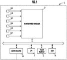
- FIG. 2 is a block diagram showing a configuration of the microphone array system 1.
- the microphone array system in addition to the six microphones of the microphone 11A, the microphone 11B, the microphone 11C, the microphone 11D, the microphone 11E, and the microphone 11F, further includes a beamforming processor 15, a communicator 16, a CPU 17, a flash memory 18, and a RAM 19.
- the CPU 17 is a controller that controls an operation of the microphone array system 1.
- the CPU 17 reads and implements a predetermined program stored in the flash memory 18 being a storage medium to the RAM 19 and performs various types of operations.
- the CPU 17 controls the beamforming processor 15 by the program.
- the program that the CPU 17 reads does not need to be stored in the flash memory 18 in the own device.
- the program may be stored in a storage medium of an external device such as a server.
- the CPU 17 may read the program each time from the server to the RAM 19 and may execute the program.
- the beamforming processor 15 includes a DSP (a Digital Signal Processor).
- the beamforming processor 15 obtains an audio signal from the microphone 11A, the microphone 11B, the microphone 11C, the microphone 11D, the microphone 11E, and the microphone 11F.
- the beamforming processor 15 performs beamforming by performing filter processing on each audio signal obtained from the microphone 11A, the microphone 11B, the microphone 11C, the microphone 11D, the microphone 11E, and the microphone 11F and combining the audio signals.
- the signal processing according to the beamforming can be any processing such as the Delay Sum type, the Griffiths Jim type, the Henry cox type, the Sidelobe Canceller type, or the Frost Adaptive Beamformer.
- the CPU 17 determines the content of the filter processing of the beamforming processor 15, and controls the beamforming of the beamforming processor 15. For example, the CPU 17 controls the beamforming processor 15 to detect a position of a talker and to direct a beam to the position of a detected talker. The beamforming processor 15 obtains the voice of a talker with a high SN ratio by performing beamforming.
- the communicator 16 sends the audio signal on which the beamforming has been performed by the beamforming processor 15 to a different device.
- the different device is an information processor installed in a remote place, for example.
- the microphone array system 1 sends the voice of a talker to an information processor in a remote place.
- the microphone array system 1 functions as one component of a communication system for performing voice conversation with a remote place.
- the microphone 11A and the microphone 11B are disposed on a first axis A1 in the horizontal direction X1.
- the microphone 11C and the microphone 11D are disposed along a second axis A21 in the vertical (perpendicular) direction Y1 orthogonal to the first axis A1.
- the microphone 11E and the microphone 11F are disposed along a second axis A22 in the vertical (perpendicular) direction Y1 orthogonal to the first axis A1.
- Each of the microphone 11C and the microphone 11D is disposed at a position away from the first axis A1 by a distance H1 in an upward direction.
- each of the microphone 11E and the microphone 11F is disposed at a position away from the first axis A1 by a distance H2 in a downward direction.
- a first distance H1 and a first distance H2 are the same distance.
- the microphone 11A and the microphone 11B configure a plurality of first microphones disposed along the first axis A1.
- the equal intervals according to the present embodiment are not only the exact same intervals.
- the equal intervals may include intervals with an error of about ⁇ 5%.
- the microphone 11C, the microphone 11D, the microphone 11E, and the microphone 11F are projected onto the first axis A1, all the microphones on the first axis A1 are arranged at equal intervals.
- the microphone 11A, the virtual microphone 11N1, the virtual microphone 11N2, and the microphone 11B are disposed at equal intervals of a second distance.
- a second distance D1 between the virtual microphone 11N1 and the microphone 11A, a second distance D2 between the virtual microphone 11N2 and the virtual microphone 11N1, and a second distance D3 between the microphone 11B and the virtual microphone 11N2 are all the same distance.
- the microphone array configured by the microphone 11A, the microphone 11B, the microphone 11C, the microphone 11D, the microphone 11E, and the microphone 11F, in beamforming in the horizontal direction X1, is equivalent to using audio signals of the four microphones (the microphone 11A, the virtual microphone 11N1, the virtual microphone 11N2, and the microphone 11B) arranged on the first axis A1.
- D1 the second distance
- ripples appearing due to the Gibbs phenomenon are larger than when beamforming is performed by microphones arrayed at different intervals. Accordingly, the interaction (resonance) of the four microphones causes the SN ratio to be higher or lower at a specific frequency.
- FIG. 3 shows a directivity coefficient k1 of the microphone array system 1.
- the horizontal axis represents a frequency and the vertical axis represents a directivity coefficient.
- the directivity coefficient k1 corresponds to a relative SN ratio in a case in which the six microphones of the microphone 11A, the microphone 11B, the microphone 11C, the microphone 11D, the microphone 11E, and the microphone 11F are combined and assumed to be one single microphone with respect to a single microphone (the microphone 11A, for example).
- the microphone array system 1 produces a peak in the SN ratio at a specific frequency that depends on a distance between microphones due to the interaction between the microphone 11A and the virtual microphone 11N1, the virtual microphone 11N1 and the virtual microphone 11N2, and the microphone 11B and the virtual microphone 11N2.
- the peak is produced periodically at a plurality of frequencies in order from the lowest frequency.
- FIG. 3 shows directivity characteristics in a case in which second distances (D1 + D2 + D3) between the microphone 11A and the microphone 11B disposed at opposite ends is about 1 m.
- each of the second distances D1, D2, D3 is set to about 33 cm. Accordingly, as shown in FIG. 3 , a peak is produced at about 1 kHz at the lowest frequency. In addition, in a frequency band higher than 1 kHz, a peak is produced periodically at a plurality of frequencies.
- the peak at the lowest frequency (hereinafter referred to as the lowest peak) varies with the distance between the microphone 11A and the microphone 11B, that is, the second distance D1, D2, D3.
- the frequency of the lowest peak is lower as the second distance D1, D2, D3 is larger.
- the frequency of the lowest peak is about 100 Hz.
- the frequency of the lowest peak is higher as the second distance D1, D2, D3 is smaller.
- the frequency of the lowest peak is about 10 kHz.
- interior noise, reverberation, and an echo have a high level in a low frequency band of 10 kHz or less.
- interior noise, reverberation, and an echo have a higher level in a lower frequency band such as 1 kHz or less.
- the microphone array system 1 according to the present embodiment even with a small number (six) of microphones, shows a very high SN ratio in the low frequency of 1 kHz in which the influence of interior noise, reverberation, and an echo is large.
- the microphone array system 1 even with a small number of microphones, is able to improve the SN ratio in the low frequency band. Accordingly, the microphone array system 1 is able to reduce the influence of interior noise, reverberation, and an echo and provide a good directivity.
- a plurality of microphones are disposed not only in the horizontal direction X1 but also in the vertical (perpendicular) direction Y1.
- a virtual microphone 11M1 and a virtual microphone 11M2 are configured on the second axis A2.
- the microphone 11A, the virtual microphone 11M1, and the virtual microphone 11M2 on the second axis A2 are arranged at equal intervals. Therefore, the microphone array system 1 produces a peak in the SN ratio at a specific frequency due to the interaction of a plurality of microphones in the vertical direction Y1 as well as in the horizontal direction X1. Accordingly, the microphone array system 1 according to the present embodiment is able to perform beamforming also in the vertical direction Y1.
- the microphone array system 1 is disposed above or below the display (not shown), and collects the voice of a talker present in front of the display (not shown) .
- the talker is present at a height of about 1 m to about 2 m from a floor in the up-down direction Y1, and is rarely present at a position far beyond the range of 1 m to 2 m.
- the talker is present at various positions in the horizontal direction X1 in many cases. For example, a talker may be right in front of the display (not shown) or talkers may be at positions apart from the right and left sides.
- a distance (a distance between the microphone 11A and the microphone 11B) between opposite ends of the microphones arranged along the first axis A1 in the horizontal direction X1 is larger than a distance (a distance between the microphone 11C and the microphone 11E, for example) between opposite ends of the microphones arranged along each of the second axis A21 and the second axis A22 in the vertical direction Y1.
- the microphone array system 1 is able to improve the performance of beamforming in the horizontal direction X1 over the vertical direction Y1, and collect the voice of talkers present at various positions in the horizontal direction X1.
- the number of microphones (the microphone 11A, the virtual microphone 11N1, the virtual microphone 11N2, and the microphone 11B) arranged along the first axis A1 in the horizontal direction X1 in the microphone array system 1 is four.
- the number of microphones (the microphone 11A, the virtual microphone 11M1, the virtual microphone 11M2) arranged along the second axis A2 in the vertical direction Y1 is three.
- the number of microphones arranged along the first axis A1 in the horizontal direction X1 is larger than the number of microphones arranged along the second axis A2 in the vertical direction Y1.
- the microphone array system 1 is able to form a sharper beam in the horizontal direction X1 than in the vertical direction Y1. Accordingly, the microphone array system 1, even when a plurality of talkers are present, is able to separate and collect the voice for each talker with high accuracy.
- the second distance (D1, D2, D3) is larger than the first distance (H1, H2).
- the second distance (D1, D2, D3) may be the same as the first distance (H1, H2).
- FIG. 4 is a front view of a microphone array system 1A including eight microphones.
- the same reference numerals are used to refer to components common to FIG. 1 , and the description will be omitted.
- the microphone array system 1A further includes a microphone 11G and a microphone 11H.
- the microphone 11G is disposed at a position away from the first axis A1 by the first distance H1 in the upward direction, along a second axis A23.
- the microphone 11H is disposed at a position away from the first axis A1 by the first distance H2 in the downward direction.
- the microphone 11G and the microphone 11H when being projected onto the first axis A1, configure a virtual microphone 11N3 on the first axis A1.
- all the microphones on the first axis are arranged at equal intervals.
- a second distance D1 between the virtual microphone 11N1 and the microphone 11A, a second distance D2 between the virtual microphone 11N2 and the virtual microphone 11N1, a second distance D3 between the virtual microphone 11N3 and the virtual microphone 11N2, and a second distance D4 between the microphone 11B and the virtual microphone 11N3 are all the same.
- the microphone array system 1A even with a small number (eight) of microphones, is able to improve the SN ratio in the low frequency band.
- the microphone array system 1A with more microphones arranged in the horizontal direction X1 than the microphone array system 1 of FIG. 1 , is able to improve the SN ratio in the lower frequency band.
- FIG. 5 is a front view of a microphone array system 1B in which the first microphone (the microphone 11A and the microphone 11B) is not disposed at opposite ends.
- the same reference numerals are used to refer to components common to FIG. 1 , and the description will be omitted.
- the microphone 11C and the microphone 11E are disposed at a left end, and the microphone 11A is disposed between the virtual microphone 11N1 and the virtual microphone 11N2.
- Other configurations are the same as the configurations of the microphone array system 1 of FIG. 1 .
- the microphone array system 1B is able to improve the SN ratio in the low frequency band, even with a small number (six) of microphones.
- the present embodiment shows an example in which the number of microphones is six or eight.
- the number of microphones may be ten or more.
- the microphone array system according to the present embodiment is able to improve the SN ratio in the low frequency band even with a small number of microphones, and thus the number of microphones is able to be reduced so as to reduce the size of the housing, and the cost. Therefore, the number of microphones is preferably six or eight.
- the plurality of first microphones (the microphone 11A and the microphone 11B) and the plurality of second microphones (the microphone 11C, the microphone 11D, the microphone 11E, and the microphone 11F) may be disposed so that each of the plurality of first microphones (the microphone 11A and the microphone 11B) and a plurality of virtual microphones obtained by projecting the second microphones onto the second axis may be arranged at equal intervals on the second axis.
- the plurality of virtual microphones are configured on the second axis.
- the microphone 11B and the plurality of virtual microphones are arranged at equal intervals on the second axis.
Landscapes
- Health & Medical Sciences (AREA)
- Otolaryngology (AREA)
- Physics & Mathematics (AREA)
- Engineering & Computer Science (AREA)
- Acoustics & Sound (AREA)
- Signal Processing (AREA)
- General Health & Medical Sciences (AREA)
- Circuit For Audible Band Transducer (AREA)
- Obtaining Desirable Characteristics In Audible-Bandwidth Transducers (AREA)
Abstract
Description
- The present disclosure relates to a microphone array system including a plurality of microphones.
- National Publication of International Patent Application No.
2018-515028 discloses a microphone array system that includes a plurality of microphones disposed concentrically and performs beamsteering. The microphone array system of National Publication of International Patent Application No.2018-515028 includes tens of microphones. The microphone array system of National Publication of International Patent Application No.2018-515028 includes a large number of microphones to provide a uniform SN ratio from a low frequency band (10 kHz or less, for example) to a high frequency band (10 kHz or more, for example). - However, with a small number of microphones (less than 10, for example), it is difficult to ensure an SN ratio in the low frequency band.
- In view of the foregoing, an object of the present disclosure is to provide a microphone array system that is able to improve an SN ratio in a low frequency band, even with a small number of microphones.
- A microphone array system includes a plurality of first microphones disposed along a first axis, a plurality of second microphones disposed at equal intervals of a first distance from the first axis, along a second axis orthogonal to the first axis, a beamforming processor that performs beamforming by filtering and combining audio signals from the plurality of first microphones and the plurality of second microphones, and, when the plurality of second microphones are projected onto the first axis, the plurality of first microphones and a plurality of projected second microphones are disposed at equal intervals of a second distance, a distance between two microphones disposed at opposite ends, among the plurality of first microphones and the plurality of projected second microphones arranged along the first axis when the plurality of second microphones are projected onto the first axis, is larger than a distance between two microphones disposed at opposite ends, between the opposite ends of the plurality of first microphones and the plurality of projected second microphones arranged along the second axis when the plurality of first microphones are projected onto the second axis.
- A microphone array system is able to improve an SN ratio in a low frequency band even with a small number of microphones.
-
-
FIG. 1 is a front view of amicrophone array system 1. -
FIG. 2 is a block diagram of themicrophone array system 1. -
FIG. 3 shows a directivity coefficient of themicrophone array system 1. -
FIG. 4 is a front view of amicrophone array system 1A including eight microphones. -
FIG. 5 is a front view of amicrophone array system 1B in which a first microphone is not disposed at opposite ends. -
FIG. 1 is a front view of amicrophone array system 1. Themicrophone array system 1 includes a plurality of microphones in front of ahousing 10. Themicrophone array system 1 according to the present embodiment includes six microphones of amicrophone 11A, amicrophone 11B, amicrophone 11C, amicrophone 11D, amicrophone 11E, and amicrophone 11F. - The
housing 10 has a rectangular parallelepiped shape with a small depth, as an example. However, the shape of thehousing 10 can be any shape that allows a plurality of microphones to be disposed in front. - The
housing 10 shown inFIG. 1 has a shape that is long in a left-right direction (a horizontal direction) X1 and is short in an up-down direction Y1 (a vertical direction Y1). Thehousing 10 is disposed above or below a display (not shown), for example. Themicrophone array system 1 collects the voice of a talker present in front of the display (not shown) by using the plurality of microphones disposed in front of thehousing 10. -
FIG. 2 is a block diagram showing a configuration of themicrophone array system 1. Themicrophone array system 1, in addition to the six microphones of themicrophone 11A, themicrophone 11B, themicrophone 11C, themicrophone 11D, themicrophone 11E, and themicrophone 11F, further includes abeamforming processor 15, acommunicator 16, aCPU 17, aflash memory 18, and aRAM 19. - The
CPU 17 is a controller that controls an operation of themicrophone array system 1. TheCPU 17 reads and implements a predetermined program stored in theflash memory 18 being a storage medium to theRAM 19 and performs various types of operations. For example, theCPU 17 controls thebeamforming processor 15 by the program. - It is to be noted that the program that the
CPU 17 reads does not need to be stored in theflash memory 18 in the own device. For example, the program may be stored in a storage medium of an external device such as a server. In such a case, theCPU 17 may read the program each time from the server to theRAM 19 and may execute the program. - The
beamforming processor 15 includes a DSP (a Digital Signal Processor). Thebeamforming processor 15 obtains an audio signal from themicrophone 11A, themicrophone 11B, themicrophone 11C, themicrophone 11D, themicrophone 11E, and themicrophone 11F. Thebeamforming processor 15 performs beamforming by performing filter processing on each audio signal obtained from themicrophone 11A, themicrophone 11B, themicrophone 11C, themicrophone 11D, themicrophone 11E, and themicrophone 11F and combining the audio signals. The signal processing according to the beamforming can be any processing such as the Delay Sum type, the Griffiths Jim type, the Henry cox type, the Sidelobe Canceller type, or the Frost Adaptive Beamformer. - The
CPU 17 determines the content of the filter processing of thebeamforming processor 15, and controls the beamforming of thebeamforming processor 15. For example, theCPU 17 controls thebeamforming processor 15 to detect a position of a talker and to direct a beam to the position of a detected talker. Thebeamforming processor 15 obtains the voice of a talker with a high SN ratio by performing beamforming. - The
communicator 16 sends the audio signal on which the beamforming has been performed by thebeamforming processor 15 to a different device. The different device is an information processor installed in a remote place, for example. As a result, themicrophone array system 1 sends the voice of a talker to an information processor in a remote place. In such a case, themicrophone array system 1 functions as one component of a communication system for performing voice conversation with a remote place. - In the
microphone array system 1, as shown inFIG. 1 , themicrophone 11A and themicrophone 11B are disposed on a first axis A1 in the horizontal direction X1. In addition, in themicrophone array system 1, themicrophone 11C and themicrophone 11D are disposed along a second axis A21 in the vertical (perpendicular) direction Y1 orthogonal to the first axis A1. In addition, in themicrophone array system 1, themicrophone 11E and themicrophone 11F are disposed along a second axis A22 in the vertical (perpendicular) direction Y1 orthogonal to the first axis A1. - Each of the
microphone 11C and themicrophone 11D is disposed at a position away from the first axis A1 by a distance H1 in an upward direction. In addition, each of themicrophone 11E and themicrophone 11F is disposed at a position away from the first axis A1 by a distance H2 in a downward direction. A first distance H1 and a first distance H2 are the same distance. - In other words, the
microphone 11A and themicrophone 11B configure a plurality of first microphones disposed along the first axis A1. Themicrophone 11C, themicrophone 11D, themicrophone 11E, and themicrophone 11F configure a plurality of second microphones disposed at equal intervals of the first distance H1 (= H2) from the first axis A1. It is to be noted that the equal intervals according to the present embodiment are not only the exact same intervals. For example, the equal intervals may include intervals with an error of about ±5%. - Furthermore, when the
microphone 11C, themicrophone 11D, themicrophone 11E, and themicrophone 11F are projected onto the first axis A1, all the microphones on the first axis A1 are arranged at equal intervals. Themicrophone 11C and themicrophone 11E, when being projected onto the first axis A1, configure a virtual microphone 11N1 on the first axis A1. Themicrophone 11D and themicrophone 11F, when being projected onto the first axis A1, configure a virtual microphone 11N2 on the first axis A1. Themicrophone 11A, the virtual microphone 11N1, the virtual microphone 11N2, and themicrophone 11B are disposed at equal intervals of a second distance. A second distance D1 between the virtual microphone 11N1 and themicrophone 11A, a second distance D2 between the virtual microphone 11N2 and the virtual microphone 11N1, and a second distance D3 between themicrophone 11B and the virtual microphone 11N2 are all the same distance. - The microphone array configured by the
microphone 11A, themicrophone 11B, themicrophone 11C, themicrophone 11D, themicrophone 11E, and themicrophone 11F, in beamforming in the horizontal direction X1, is equivalent to using audio signals of the four microphones (themicrophone 11A, the virtual microphone 11N1, the virtual microphone 11N2, and themicrophone 11B) arranged on the first axis A1. - These four microphones (the
microphone 11A, the virtual microphone 11N1, the virtual microphone 11N2, and themicrophone 11B) are arrayed at equal intervals of the second distance D1 (= D2 = D3) along the first axis A1. When beamforming is performed by four microphones arrayed at equal intervals, ripples appearing due to the Gibbs phenomenon are larger than when beamforming is performed by microphones arrayed at different intervals. Accordingly, the interaction (resonance) of the four microphones causes the SN ratio to be higher or lower at a specific frequency. -
FIG. 3 shows a directivity coefficient k1 of themicrophone array system 1. In the graph shown inFIG. 3 , the horizontal axis represents a frequency and the vertical axis represents a directivity coefficient. The directivity coefficient k1 corresponds to a relative SN ratio in a case in which the six microphones of themicrophone 11A, themicrophone 11B, themicrophone 11C, themicrophone 11D, themicrophone 11E, and themicrophone 11F are combined and assumed to be one single microphone with respect to a single microphone (themicrophone 11A, for example). - The
microphone array system 1 produces a peak in the SN ratio at a specific frequency that depends on a distance between microphones due to the interaction between themicrophone 11A and the virtual microphone 11N1, the virtual microphone 11N1 and the virtual microphone 11N2, and themicrophone 11B and the virtual microphone 11N2. The peak is produced periodically at a plurality of frequencies in order from the lowest frequency. - The example in
FIG. 3 shows directivity characteristics in a case in which second distances (D1 + D2 + D3) between themicrophone 11A and themicrophone 11B disposed at opposite ends is about 1 m. In such a case, each of the second distances D1, D2, D3 is set to about 33 cm. Accordingly, as shown inFIG. 3 , a peak is produced at about 1 kHz at the lowest frequency. In addition, in a frequency band higher than 1 kHz, a peak is produced periodically at a plurality of frequencies. - The peak at the lowest frequency (hereinafter referred to as the lowest peak) varies with the distance between the
microphone 11A and themicrophone 11B, that is, the second distance D1, D2, D3. The frequency of the lowest peak is lower as the second distance D1, D2, D3 is larger. For example, when the distance between themicrophone 11A and themicrophone 11B is about 10 m, the frequency of the lowest peak is about 100 Hz. In addition, the frequency of the lowest peak is higher as the second distance D1, D2, D3 is smaller. For example, when the distance between themicrophone 11A and themicrophone 11B is about 10 cm, the frequency of the lowest peak is about 10 kHz. - Normally, interior noise, reverberation, and an echo have a high level in a low frequency band of 10 kHz or less. Particularly, interior noise, reverberation, and an echo have a higher level in a lower frequency band such as 1 kHz or less. Accordingly, for beamforming, it is important to ensure a higher SN ratio in a lower frequency band of 10 kHz or less. The
microphone array system 1 according to the present embodiment, even with a small number (six) of microphones, shows a very high SN ratio in the low frequency of 1 kHz in which the influence of interior noise, reverberation, and an echo is large. Themicrophone array system 1 according to the present embodiment, even with a small number of microphones, is able to improve the SN ratio in the low frequency band. Accordingly, themicrophone array system 1 is able to reduce the influence of interior noise, reverberation, and an echo and provide a good directivity. - In addition, in the
microphone array system 1 according to the present embodiment, a plurality of microphones are disposed not only in the horizontal direction X1 but also in the vertical (perpendicular) direction Y1. When themicrophone 11C, themicrophone 11D, themicrophone 11E, and themicrophone 11F are projected onto a second axis A2, a virtual microphone 11M1 and a virtual microphone 11M2 are configured on the second axis A2. Themicrophone 11A, the virtual microphone 11M1, and the virtual microphone 11M2 on the second axis A2 are arranged at equal intervals. Therefore, themicrophone array system 1 produces a peak in the SN ratio at a specific frequency due to the interaction of a plurality of microphones in the vertical direction Y1 as well as in the horizontal direction X1. Accordingly, themicrophone array system 1 according to the present embodiment is able to perform beamforming also in the vertical direction Y1. - As described above, the
microphone array system 1 is disposed above or below the display (not shown), and collects the voice of a talker present in front of the display (not shown) . The talker is present at a height of about 1 m to about 2 m from a floor in the up-down direction Y1, and is rarely present at a position far beyond the range of 1 m to 2 m. On the other hand, the talker is present at various positions in the horizontal direction X1 in many cases. For example, a talker may be right in front of the display (not shown) or talkers may be at positions apart from the right and left sides. - In contrast, in the
microphone array system 1, a distance (a distance between themicrophone 11A and themicrophone 11B) between opposite ends of the microphones arranged along the first axis A1 in the horizontal direction X1 is larger than a distance (a distance between themicrophone 11C and themicrophone 11E, for example) between opposite ends of the microphones arranged along each of the second axis A21 and the second axis A22 in the vertical direction Y1. As a result, themicrophone array system 1 is able to improve the performance of beamforming in the horizontal direction X1 over the vertical direction Y1, and collect the voice of talkers present at various positions in the horizontal direction X1. - In addition, the number of microphones (the
microphone 11A, the virtual microphone 11N1, the virtual microphone 11N2, and themicrophone 11B) arranged along the first axis A1 in the horizontal direction X1 in themicrophone array system 1 is four. The number of microphones (themicrophone 11A, the virtual microphone 11M1, the virtual microphone 11M2) arranged along the second axis A2 in the vertical direction Y1 is three. In other words, the number of microphones arranged along the first axis A1 in the horizontal direction X1 is larger than the number of microphones arranged along the second axis A2 in the vertical direction Y1. As a result, themicrophone array system 1 is able to form a sharper beam in the horizontal direction X1 than in the vertical direction Y1. Accordingly, themicrophone array system 1, even when a plurality of talkers are present, is able to separate and collect the voice for each talker with high accuracy. - It is to be noted that, in the
microphone array system 1 shown inFIG. 1 , the second distance (D1, D2, D3) is larger than the first distance (H1, H2). However, the second distance (D1, D2, D3) may be the same as the first distance (H1, H2). - In addition, the
microphone array system 1 ofFIG. 1 shows an example in which six microphones are provided. However, the number of microphones is not limited to six. For example,FIG. 4 is a front view of amicrophone array system 1A including eight microphones. The same reference numerals are used to refer to components common toFIG. 1 , and the description will be omitted. - The
microphone array system 1A further includes a microphone 11G and amicrophone 11H. The microphone 11G is disposed at a position away from the first axis A1 by the first distance H1 in the upward direction, along a second axis A23. Themicrophone 11H is disposed at a position away from the first axis A1 by the first distance H2 in the downward direction. In other words, the microphone 11G and themicrophone 11H configure a plurality of second microphones disposed at equal intervals of the first distance H1 (= H2) from the first axis A1. - The microphone 11G and the
microphone 11H, when being projected onto the first axis A1, configure a virtual microphone 11N3 on the first axis A1. When the microphone 11G and themicrophone 11H are projected onto the first axis A1, all the microphones on the first axis are arranged at equal intervals. A second distance D1 between the virtual microphone 11N1 and themicrophone 11A, a second distance D2 between the virtual microphone 11N2 and the virtual microphone 11N1, a second distance D3 between the virtual microphone 11N3 and the virtual microphone 11N2, and a second distance D4 between themicrophone 11B and the virtual microphone 11N3 are all the same. - In such a case as well, as with the
microphone array system 1 ofFIG. 1 , a peak is produced in the SN ratio at a specific frequency due to the interaction of a plurality of microphones arranged in the horizontal direction X1. Accordingly, themicrophone array system 1A, even with a small number (eight) of microphones, is able to improve the SN ratio in the low frequency band. Themicrophone array system 1A, with more microphones arranged in the horizontal direction X1 than themicrophone array system 1 ofFIG. 1 , is able to improve the SN ratio in the lower frequency band. - In addition, the first microphone (the
microphone 11A and themicrophone 11B, for example) disposed on the first axis A1 does not need to be disposed at opposite ends. For example,FIG. 5 is a front view of amicrophone array system 1B in which the first microphone (themicrophone 11A and themicrophone 11B) is not disposed at opposite ends. The same reference numerals are used to refer to components common toFIG. 1 , and the description will be omitted. - In the
microphone array system 1B, in a front view, themicrophone 11C and themicrophone 11E are disposed at a left end, and themicrophone 11A is disposed between the virtual microphone 11N1 and the virtual microphone 11N2. Other configurations are the same as the configurations of themicrophone array system 1 ofFIG. 1 . - In such a case as well, when the
microphone 11C, themicrophone 11D, themicrophone 11E, and themicrophone 11F are projected onto the first axis A1, all the microphones on the first axis A1 are arranged at equal intervals. Accordingly, themicrophone array system 1B, as with themicrophone array system 1 ofFIG. 1 , is able to improve the SN ratio in the low frequency band, even with a small number (six) of microphones. - For example, the present embodiment shows an example in which the number of microphones is six or eight. However, the number of microphones may be ten or more. However, the microphone array system according to the present embodiment is able to improve the SN ratio in the low frequency band even with a small number of microphones, and thus the number of microphones is able to be reduced so as to reduce the size of the housing, and the cost. Therefore, the number of microphones is preferably six or eight.
- In addition, in the present embodiment, the plurality of first microphones (the
microphone 11A and themicrophone 11B) and the plurality of second microphones (themicrophone 11C, themicrophone 11D, themicrophone 11E, and themicrophone 11F) may be disposed so that each of the plurality of first microphones (themicrophone 11A and themicrophone 11B) and a plurality of virtual microphones obtained by projecting the second microphones onto the second axis may be arranged at equal intervals on the second axis. In such a case, for example, when themicrophone 11C, themicrophone 11D, themicrophone 11E, and themicrophone 11F are projected onto the second axis orthogonal to the first axis A1 at the position of themicrophone 11B, the plurality of virtual microphones are configured on the second axis. Themicrophone 11B and the plurality of virtual microphones are arranged at equal intervals on the second axis.
Claims (7)
- A microphone array system (1)comprising:a plurality of first microphones (11A, 11B) disposed along a first axis (A1);a plurality of second microphones (11C, 11D, 11E, 11F) disposed at equal intervals of a first distance (H1, H2)from the first axis (A1), along a second axis (A2) orthogonal to the first axis (A1); anda beamforming processor (15) that performs beamforming by filtering and combining audio signals from the plurality of first microphones (11A, 11B) and the plurality of second microphones (11C, 11D, 11E, 11F), wherein:when the plurality of second microphones (11C, 11D, 11E, 11F) are projected onto the first axis (A1), the plurality of first microphones (11A, 11B) and a plurality of projected second microphones (11N1, 11N2) are disposed at equal intervals of a second distance (D1, D2, D3); anda distance between two microphones (11A, 11B) disposed at opposite ends, among the plurality of first microphones (11A, 11B) and the plurality of projected second microphones (11N1, 11N2) arranged along the first axis (A1) when the plurality of second microphones (11N1, 11N2) are projected onto the first axis (A1), is larger than a distance between two microphones (11M1, 11M2) disposed at opposite ends, between the opposite ends of the plurality of first microphones (11A, 11B) and the plurality of projected second microphones (11M1, 11M2) arranged along the second axis (A2) when the plurality of second microphones (11C, 11D, 11E, 11F) are projected onto the second axis (A2).
- The microphone array system (1) according to claim 1, wherein a number of first microphones (11A, 11B) and projected second microphones (11N1, 11N2) arranged along the first axis (A1) when the plurality of second microphones (11N1, 11N2) are projected onto the first axis (A1), is larger than a number of projected second microphones (11M1, 11M2) and first microphones (11A) arranged along the second axis (A2) when the plurality of second microphones (11M1, 11M2) are projected onto the second axis (A2).
- The microphone array system (1) according to claim 1 or 2, wherein the second distance (D1, D2, D3) is larger than the first distance (H1, H2).
- The microphone array system (1) according to claim 1 or 2, wherein the first distance (H1, H2) is equal to the second distance (D1, D2, D3).
- The microphone array system (1) according to any one of claims 1 to 4, wherein the distance between two microphones (11A, 11B) disposed at opposite ends, among the plurality of first microphones (11A, 11B) and the plurality of projected second microphones (11N1, 11N2) arranged along the first axis (A1) when the plurality of second microphones (11C, 11D, 11E, 11F) are projected onto the first axis (A1), is 10 cm or more and 10 m or less.
- The microphone array system (1) according to any one of claims 1 to 5, wherein a number of first microphones (11A, 11B) and second microphones (11C, 11D, 11E, 11F) is six or more in total.
- The microphone array system (1) according to claim 6, wherein the number of first microphones (11A, 11B) and second microphones (11C, 11D, 11E, 11F) is eight or less in total.
Applications Claiming Priority (1)
| Application Number | Priority Date | Filing Date | Title |
|---|---|---|---|
| JP2020169748A JP7618995B2 (en) | 2020-10-07 | 2020-10-07 | Microphone Array System |
Publications (1)
| Publication Number | Publication Date |
|---|---|
| EP3982644A1 true EP3982644A1 (en) | 2022-04-13 |
Family
ID=78080197
Family Applications (1)
| Application Number | Title | Priority Date | Filing Date |
|---|---|---|---|
| EP21201059.9A Pending EP3982644A1 (en) | 2020-10-07 | 2021-10-05 | Microphone array system |
Country Status (4)
| Country | Link |
|---|---|
| US (1) | US11589158B2 (en) |
| EP (1) | EP3982644A1 (en) |
| JP (1) | JP7618995B2 (en) |
| CN (1) | CN114302293A (en) |
Families Citing this family (1)
| Publication number | Priority date | Publication date | Assignee | Title |
|---|---|---|---|---|
| CN118828302B (en) * | 2023-04-21 | 2025-10-31 | 北京小米移动软件有限公司 | Terminal, sound pickup method, sound pickup apparatus, and storage medium |
Citations (4)
| Publication number | Priority date | Publication date | Assignee | Title |
|---|---|---|---|---|
| EP1524879A1 (en) * | 2003-06-30 | 2005-04-20 | Harman Becker Automotive Systems GmbH | Handsfree system for use in a vehicle |
| US20120076316A1 (en) * | 2010-09-24 | 2012-03-29 | Manli Zhu | Microphone Array System |
| US9966059B1 (en) * | 2017-09-06 | 2018-05-08 | Amazon Technologies, Inc. | Reconfigurale fixed beam former using given microphone array |
| JP2018515028A (en) | 2015-04-30 | 2018-06-07 | シュアー アクイジッション ホールディングス インコーポレイテッドShure Acquisition Holdings,Inc. | Array microphone system and method of assembling array microphone system |
Family Cites Families (3)
| Publication number | Priority date | Publication date | Assignee | Title |
|---|---|---|---|---|
| US9973848B2 (en) * | 2011-06-21 | 2018-05-15 | Amazon Technologies, Inc. | Signal-enhancing beamforming in an augmented reality environment |
| JP6640703B2 (en) | 2016-12-14 | 2020-02-05 | 株式会社東芝 | Electronic device, method and program |
| WO2021041275A1 (en) * | 2019-08-23 | 2021-03-04 | Shore Acquisition Holdings, Inc. | Two-dimensional microphone array with improved directivity |
-
2020
- 2020-10-07 JP JP2020169748A patent/JP7618995B2/en active Active
-
2021
- 2021-09-27 CN CN202111132861.1A patent/CN114302293A/en active Pending
- 2021-10-01 US US17/449,681 patent/US11589158B2/en active Active
- 2021-10-05 EP EP21201059.9A patent/EP3982644A1/en active Pending
Patent Citations (4)
| Publication number | Priority date | Publication date | Assignee | Title |
|---|---|---|---|---|
| EP1524879A1 (en) * | 2003-06-30 | 2005-04-20 | Harman Becker Automotive Systems GmbH | Handsfree system for use in a vehicle |
| US20120076316A1 (en) * | 2010-09-24 | 2012-03-29 | Manli Zhu | Microphone Array System |
| JP2018515028A (en) | 2015-04-30 | 2018-06-07 | シュアー アクイジッション ホールディングス インコーポレイテッドShure Acquisition Holdings,Inc. | Array microphone system and method of assembling array microphone system |
| US9966059B1 (en) * | 2017-09-06 | 2018-05-08 | Amazon Technologies, Inc. | Reconfigurale fixed beam former using given microphone array |
Also Published As
| Publication number | Publication date |
|---|---|
| US11589158B2 (en) | 2023-02-21 |
| JP7618995B2 (en) | 2025-01-22 |
| US20220109928A1 (en) | 2022-04-07 |
| CN114302293A (en) | 2022-04-08 |
| JP2022061673A (en) | 2022-04-19 |
Similar Documents
| Publication | Publication Date | Title |
|---|---|---|
| US11297419B2 (en) | Array microphone and sound collection method | |
| EP2262278B1 (en) | Speech processing device | |
| CN103000185B (en) | Processing signals | |
| US9641929B2 (en) | Audio signal processing method and apparatus and differential beamforming method and apparatus | |
| US9961437B2 (en) | Dome shaped microphone array with circularly distributed microphones | |
| KR101566649B1 (en) | Near-field null and beamforming | |
| US9922663B2 (en) | Voice signal processing method and apparatus | |
| US6990193B2 (en) | Method of acoustic echo cancellation in full-duplex hands free audio conferencing with spatial directivity | |
| US9641688B2 (en) | Conferencing apparatus with an automatically adapting beamforming microphone array | |
| US10687139B2 (en) | Directional audio pickup in collaboration endpoints | |
| US9990939B2 (en) | Methods and apparatus for broadened beamwidth beamforming and postfiltering | |
| US11134339B2 (en) | Asymmetric microphone array for speaker system | |
| CN104429100A (en) | System and method for surround sound echo reduction | |
| US8300839B2 (en) | Sound emission and collection apparatus and control method of sound emission and collection apparatus | |
| Derkx et al. | Theoretical analysis of a first-order azimuth-steerable superdirective microphone array | |
| US11589158B2 (en) | Microphone array system | |
| US20240185876A1 (en) | Sound signal processing method and apparatus, and computer-readable storage medium | |
| US10356508B2 (en) | Sound collecting apparatus | |
| US9420115B2 (en) | Method using array microphone to cancel echo | |
| CN115515038B (en) | Beam forming method, device and equipment | |
| US11778379B2 (en) | System and method for omnidirectional adaptive loudspeaker | |
| KR102848942B1 (en) | Method for processing audio data and electronic device supporting the same | |
| US20220174420A1 (en) | Sounding device | |
| JP2007027939A (en) | Acoustic signal processing device | |
| US20230262374A1 (en) | Sound pickup device |
Legal Events
| Date | Code | Title | Description |
|---|---|---|---|
| PUAI | Public reference made under article 153(3) epc to a published international application that has entered the european phase |
Free format text: ORIGINAL CODE: 0009012 |
|
| STAA | Information on the status of an ep patent application or granted ep patent |
Free format text: STATUS: THE APPLICATION HAS BEEN PUBLISHED |
|
| AK | Designated contracting states |
Kind code of ref document: A1 Designated state(s): AL AT BE BG CH CY CZ DE DK EE ES FI FR GB GR HR HU IE IS IT LI LT LU LV MC MK MT NL NO PL PT RO RS SE SI SK SM TR |
|
| STAA | Information on the status of an ep patent application or granted ep patent |
Free format text: STATUS: REQUEST FOR EXAMINATION WAS MADE |
|
| 17P | Request for examination filed |
Effective date: 20221012 |
|
| RBV | Designated contracting states (corrected) |
Designated state(s): AL AT BE BG CH CY CZ DE DK EE ES FI FR GB GR HR HU IE IS IT LI LT LU LV MC MK MT NL NO PL PT RO RS SE SI SK SM TR |
|
| STAA | Information on the status of an ep patent application or granted ep patent |
Free format text: STATUS: EXAMINATION IS IN PROGRESS |
|
| 17Q | First examination report despatched |
Effective date: 20240313 |