EP3982438A1 - Electrode moulded body production method - Google Patents
Electrode moulded body production method Download PDFInfo
- Publication number
- EP3982438A1 EP3982438A1 EP20854716.6A EP20854716A EP3982438A1 EP 3982438 A1 EP3982438 A1 EP 3982438A1 EP 20854716 A EP20854716 A EP 20854716A EP 3982438 A1 EP3982438 A1 EP 3982438A1
- Authority
- EP
- European Patent Office
- Prior art keywords
- electrode material
- retaining member
- electrode
- opening portion
- shape retaining
- Prior art date
- Legal status (The legal status is an assumption and is not a legal conclusion. Google has not performed a legal analysis and makes no representation as to the accuracy of the status listed.)
- Pending
Links
- 238000004519 manufacturing process Methods 0.000 title claims abstract description 64
- 239000007772 electrode material Substances 0.000 claims abstract description 257
- 238000007599 discharging Methods 0.000 claims abstract description 7
- 239000007784 solid electrolyte Substances 0.000 description 60
- 229910003480 inorganic solid Inorganic materials 0.000 description 57
- 239000012752 auxiliary agent Substances 0.000 description 44
- 239000002904 solvent Substances 0.000 description 44
- 238000000034 method Methods 0.000 description 41
- -1 transition metal halogenated phosphate compounds Chemical class 0.000 description 38
- 239000002245 particle Substances 0.000 description 33
- 239000000843 powder Substances 0.000 description 30
- 239000007773 negative electrode material Substances 0.000 description 25
- 239000007774 positive electrode material Substances 0.000 description 25
- 239000008151 electrolyte solution Substances 0.000 description 23
- 238000009826 distribution Methods 0.000 description 22
- 229910052744 lithium Inorganic materials 0.000 description 21
- 239000011230 binding agent Substances 0.000 description 20
- WHXSMMKQMYFTQS-UHFFFAOYSA-N Lithium Chemical compound [Li] WHXSMMKQMYFTQS-UHFFFAOYSA-N 0.000 description 19
- UCKMPCXJQFINFW-UHFFFAOYSA-N Sulphide Chemical compound [S-2] UCKMPCXJQFINFW-UHFFFAOYSA-N 0.000 description 19
- 229910052782 aluminium Inorganic materials 0.000 description 19
- OKTJSMMVPCPJKN-UHFFFAOYSA-N Carbon Chemical compound [C] OKTJSMMVPCPJKN-UHFFFAOYSA-N 0.000 description 17
- 239000007788 liquid Substances 0.000 description 17
- 239000010936 titanium Substances 0.000 description 17
- HBBGRARXTFLTSG-UHFFFAOYSA-N Lithium ion Chemical compound [Li+] HBBGRARXTFLTSG-UHFFFAOYSA-N 0.000 description 15
- PXHVJJICTQNCMI-UHFFFAOYSA-N Nickel Chemical compound [Ni] PXHVJJICTQNCMI-UHFFFAOYSA-N 0.000 description 15
- 229910001416 lithium ion Inorganic materials 0.000 description 15
- 230000001105 regulatory effect Effects 0.000 description 15
- 150000001875 compounds Chemical class 0.000 description 14
- 229910003002 lithium salt Inorganic materials 0.000 description 14
- 239000000463 material Substances 0.000 description 14
- 229910052751 metal Inorganic materials 0.000 description 14
- 239000000203 mixture Substances 0.000 description 14
- 229920000193 polymethacrylate Polymers 0.000 description 14
- 229910052710 silicon Inorganic materials 0.000 description 14
- 239000007787 solid Substances 0.000 description 14
- 239000002184 metal Substances 0.000 description 13
- 230000001681 protective effect Effects 0.000 description 13
- 229910052719 titanium Inorganic materials 0.000 description 13
- 229910000314 transition metal oxide Inorganic materials 0.000 description 13
- YXFVVABEGXRONW-UHFFFAOYSA-N Toluene Chemical compound CC1=CC=CC=C1 YXFVVABEGXRONW-UHFFFAOYSA-N 0.000 description 12
- 239000011149 active material Substances 0.000 description 12
- GLNWILHOFOBOFD-UHFFFAOYSA-N lithium sulfide Chemical compound [Li+].[Li+].[S-2] GLNWILHOFOBOFD-UHFFFAOYSA-N 0.000 description 12
- 239000000126 substance Substances 0.000 description 12
- 239000010410 layer Substances 0.000 description 11
- 230000002093 peripheral effect Effects 0.000 description 11
- IMNFDUFMRHMDMM-UHFFFAOYSA-N N-Heptane Chemical compound CCCCCCC IMNFDUFMRHMDMM-UHFFFAOYSA-N 0.000 description 10
- XAGFODPZIPBFFR-UHFFFAOYSA-N aluminium Chemical compound [Al] XAGFODPZIPBFFR-UHFFFAOYSA-N 0.000 description 10
- 239000002270 dispersing agent Substances 0.000 description 10
- 230000006872 improvement Effects 0.000 description 10
- 159000000002 lithium salts Chemical class 0.000 description 10
- 229920000049 Carbon (fiber) Polymers 0.000 description 9
- RYGMFSIKBFXOCR-UHFFFAOYSA-N Copper Chemical compound [Cu] RYGMFSIKBFXOCR-UHFFFAOYSA-N 0.000 description 9
- RTAQQCXQSZGOHL-UHFFFAOYSA-N Titanium Chemical compound [Ti] RTAQQCXQSZGOHL-UHFFFAOYSA-N 0.000 description 9
- 239000010949 copper Substances 0.000 description 9
- 238000010586 diagram Methods 0.000 description 9
- 230000033001 locomotion Effects 0.000 description 9
- 238000005259 measurement Methods 0.000 description 9
- 239000000758 substrate Substances 0.000 description 9
- 239000002344 surface layer Substances 0.000 description 9
- 229910052718 tin Inorganic materials 0.000 description 9
- 229910008323 Li-P-S Inorganic materials 0.000 description 8
- 229910006736 Li—P—S Inorganic materials 0.000 description 8
- MCMNRKCIXSYSNV-UHFFFAOYSA-N Zirconium dioxide Chemical compound O=[Zr]=O MCMNRKCIXSYSNV-UHFFFAOYSA-N 0.000 description 8
- 239000004917 carbon fiber Substances 0.000 description 8
- 239000003575 carbonaceous material Substances 0.000 description 8
- 239000011248 coating agent Substances 0.000 description 8
- 229920001577 copolymer Polymers 0.000 description 8
- 229910052802 copper Inorganic materials 0.000 description 8
- 239000003792 electrolyte Substances 0.000 description 8
- 229910052733 gallium Inorganic materials 0.000 description 8
- 239000010935 stainless steel Substances 0.000 description 8
- 229910001220 stainless steel Inorganic materials 0.000 description 8
- 229910052731 fluorine Inorganic materials 0.000 description 7
- 229910052732 germanium Inorganic materials 0.000 description 7
- 239000011521 glass Substances 0.000 description 7
- 229910002804 graphite Inorganic materials 0.000 description 7
- 239000010439 graphite Substances 0.000 description 7
- 150000002500 ions Chemical class 0.000 description 7
- 229910052759 nickel Inorganic materials 0.000 description 7
- 229910052717 sulfur Inorganic materials 0.000 description 7
- 239000011800 void material Substances 0.000 description 7
- OKKJLVBELUTLKV-UHFFFAOYSA-N Methanol Chemical compound OC OKKJLVBELUTLKV-UHFFFAOYSA-N 0.000 description 6
- XUIMIQQOPSSXEZ-UHFFFAOYSA-N Silicon Chemical compound [Si] XUIMIQQOPSSXEZ-UHFFFAOYSA-N 0.000 description 6
- 150000004770 chalcogenides Chemical class 0.000 description 6
- 239000002905 metal composite material Substances 0.000 description 6
- 238000002156 mixing Methods 0.000 description 6
- 239000000123 paper Substances 0.000 description 6
- 230000000737 periodic effect Effects 0.000 description 6
- 229920005989 resin Polymers 0.000 description 6
- 239000011347 resin Substances 0.000 description 6
- 229920002050 silicone resin Polymers 0.000 description 6
- 229910052799 carbon Inorganic materials 0.000 description 5
- 230000000052 comparative effect Effects 0.000 description 5
- RTZKZFJDLAIYFH-UHFFFAOYSA-N ether Substances CCOCC RTZKZFJDLAIYFH-UHFFFAOYSA-N 0.000 description 5
- 238000010304 firing Methods 0.000 description 5
- 230000001965 increasing effect Effects 0.000 description 5
- 229910044991 metal oxide Inorganic materials 0.000 description 5
- 150000004706 metal oxides Chemical class 0.000 description 5
- 229910052698 phosphorus Inorganic materials 0.000 description 5
- CYQAYERJWZKYML-UHFFFAOYSA-N phosphorus pentasulfide Chemical compound S1P(S2)(=S)SP3(=S)SP1(=S)SP2(=S)S3 CYQAYERJWZKYML-UHFFFAOYSA-N 0.000 description 5
- 239000002994 raw material Substances 0.000 description 5
- 229910052723 transition metal Inorganic materials 0.000 description 5
- XLYOFNOQVPJJNP-UHFFFAOYSA-N water Substances O XLYOFNOQVPJJNP-UHFFFAOYSA-N 0.000 description 5
- 229910000881 Cu alloy Inorganic materials 0.000 description 4
- LYCAIKOWRPUZTN-UHFFFAOYSA-N Ethylene glycol Chemical compound OCCO LYCAIKOWRPUZTN-UHFFFAOYSA-N 0.000 description 4
- 230000002378 acidificating effect Effects 0.000 description 4
- 239000007864 aqueous solution Substances 0.000 description 4
- 229910052796 boron Inorganic materials 0.000 description 4
- 238000000576 coating method Methods 0.000 description 4
- 239000013078 crystal Substances 0.000 description 4
- 239000006185 dispersion Substances 0.000 description 4
- 239000000835 fiber Substances 0.000 description 4
- 125000001153 fluoro group Chemical group F* 0.000 description 4
- 125000000524 functional group Chemical group 0.000 description 4
- 229910052738 indium Inorganic materials 0.000 description 4
- 229910001386 lithium phosphate Inorganic materials 0.000 description 4
- 125000002496 methyl group Chemical group [H]C([H])([H])* 0.000 description 4
- 229910052758 niobium Inorganic materials 0.000 description 4
- 239000010955 niobium Substances 0.000 description 4
- 229920001343 polytetrafluoroethylene Polymers 0.000 description 4
- 239000004810 polytetrafluoroethylene Substances 0.000 description 4
- 238000002360 preparation method Methods 0.000 description 4
- 239000000047 product Substances 0.000 description 4
- VYPSYNLAJGMNEJ-UHFFFAOYSA-N silicon dioxide Inorganic materials O=[Si]=O VYPSYNLAJGMNEJ-UHFFFAOYSA-N 0.000 description 4
- 238000012360 testing method Methods 0.000 description 4
- TWQULNDIKKJZPH-UHFFFAOYSA-K trilithium;phosphate Chemical compound [Li+].[Li+].[Li+].[O-]P([O-])([O-])=O TWQULNDIKKJZPH-UHFFFAOYSA-K 0.000 description 4
- ZWEHNKRNPOVVGH-UHFFFAOYSA-N 2-Butanone Chemical compound CCC(C)=O ZWEHNKRNPOVVGH-UHFFFAOYSA-N 0.000 description 3
- CSCPPACGZOOCGX-UHFFFAOYSA-N Acetone Chemical compound CC(C)=O CSCPPACGZOOCGX-UHFFFAOYSA-N 0.000 description 3
- WEVYAHXRMPXWCK-UHFFFAOYSA-N Acetonitrile Chemical compound CC#N WEVYAHXRMPXWCK-UHFFFAOYSA-N 0.000 description 3
- 229910000838 Al alloy Inorganic materials 0.000 description 3
- UHOVQNZJYSORNB-UHFFFAOYSA-N Benzene Chemical compound C1=CC=CC=C1 UHOVQNZJYSORNB-UHFFFAOYSA-N 0.000 description 3
- 229910009297 Li2S-P2S5 Inorganic materials 0.000 description 3
- 229910009176 Li2S—P2 Inorganic materials 0.000 description 3
- 229910009228 Li2S—P2S5 Inorganic materials 0.000 description 3
- 229910032387 LiCoO2 Inorganic materials 0.000 description 3
- ZMXDDKWLCZADIW-UHFFFAOYSA-N N,N-Dimethylformamide Chemical compound CN(C)C=O ZMXDDKWLCZADIW-UHFFFAOYSA-N 0.000 description 3
- OAICVXFJPJFONN-UHFFFAOYSA-N Phosphorus Chemical compound [P] OAICVXFJPJFONN-UHFFFAOYSA-N 0.000 description 3
- DNIAPMSPPWPWGF-UHFFFAOYSA-N Propylene glycol Chemical compound CC(O)CO DNIAPMSPPWPWGF-UHFFFAOYSA-N 0.000 description 3
- NINIDFKCEFEMDL-UHFFFAOYSA-N Sulfur Chemical compound [S] NINIDFKCEFEMDL-UHFFFAOYSA-N 0.000 description 3
- ZMANZCXQSJIPKH-UHFFFAOYSA-N Triethylamine Chemical compound CCN(CC)CC ZMANZCXQSJIPKH-UHFFFAOYSA-N 0.000 description 3
- 150000007824 aliphatic compounds Chemical class 0.000 description 3
- 229910052787 antimony Inorganic materials 0.000 description 3
- 239000002216 antistatic agent Substances 0.000 description 3
- 150000001491 aromatic compounds Chemical class 0.000 description 3
- 239000011324 bead Substances 0.000 description 3
- BTANRVKWQNVYAZ-UHFFFAOYSA-N butan-2-ol Chemical compound CCC(C)O BTANRVKWQNVYAZ-UHFFFAOYSA-N 0.000 description 3
- 238000006243 chemical reaction Methods 0.000 description 3
- 239000011246 composite particle Substances 0.000 description 3
- 239000000470 constituent Substances 0.000 description 3
- 125000004093 cyano group Chemical group *C#N 0.000 description 3
- 230000006866 deterioration Effects 0.000 description 3
- MTHSVFCYNBDYFN-UHFFFAOYSA-N diethylene glycol Chemical compound OCCOCCO MTHSVFCYNBDYFN-UHFFFAOYSA-N 0.000 description 3
- 230000000694 effects Effects 0.000 description 3
- 235000019441 ethanol Nutrition 0.000 description 3
- 239000002241 glass-ceramic Substances 0.000 description 3
- 125000002887 hydroxy group Chemical group [H]O* 0.000 description 3
- 239000011572 manganese Substances 0.000 description 3
- 238000003701 mechanical milling Methods 0.000 description 3
- 150000002739 metals Chemical class 0.000 description 3
- 239000000178 monomer Substances 0.000 description 3
- VLKZOEOYAKHREP-UHFFFAOYSA-N n-Hexane Chemical compound CCCCCC VLKZOEOYAKHREP-UHFFFAOYSA-N 0.000 description 3
- 229910052757 nitrogen Inorganic materials 0.000 description 3
- 239000003960 organic solvent Substances 0.000 description 3
- 229910052760 oxygen Inorganic materials 0.000 description 3
- 239000011574 phosphorus Substances 0.000 description 3
- 229920002239 polyacrylonitrile Polymers 0.000 description 3
- 238000003825 pressing Methods 0.000 description 3
- 230000009467 reduction Effects 0.000 description 3
- LIVNPJMFVYWSIS-UHFFFAOYSA-N silicon monoxide Chemical class [Si-]#[O+] LIVNPJMFVYWSIS-UHFFFAOYSA-N 0.000 description 3
- 239000011593 sulfur Substances 0.000 description 3
- 229910052715 tantalum Inorganic materials 0.000 description 3
- XOLBLPGZBRYERU-UHFFFAOYSA-N tin dioxide Chemical compound O=[Sn]=O XOLBLPGZBRYERU-UHFFFAOYSA-N 0.000 description 3
- PUPZLCDOIYMWBV-UHFFFAOYSA-N (+/-)-1,3-Butanediol Chemical compound CC(O)CCO PUPZLCDOIYMWBV-UHFFFAOYSA-N 0.000 description 2
- ARXJGSRGQADJSQ-UHFFFAOYSA-N 1-methoxypropan-2-ol Chemical compound COCC(C)O ARXJGSRGQADJSQ-UHFFFAOYSA-N 0.000 description 2
- SVTBMSDMJJWYQN-UHFFFAOYSA-N 2-methylpentane-2,4-diol Chemical compound CC(O)CC(C)(C)O SVTBMSDMJJWYQN-UHFFFAOYSA-N 0.000 description 2
- DLFVBJFMPXGRIB-UHFFFAOYSA-N Acetamide Chemical compound CC(N)=O DLFVBJFMPXGRIB-UHFFFAOYSA-N 0.000 description 2
- 239000004925 Acrylic resin Substances 0.000 description 2
- 229920000178 Acrylic resin Polymers 0.000 description 2
- 239000004215 Carbon black (E152) Substances 0.000 description 2
- LCGLNKUTAGEVQW-UHFFFAOYSA-N Dimethyl ether Chemical compound COC LCGLNKUTAGEVQW-UHFFFAOYSA-N 0.000 description 2
- LFQSCWFLJHTTHZ-UHFFFAOYSA-N Ethanol Chemical compound CCO LFQSCWFLJHTTHZ-UHFFFAOYSA-N 0.000 description 2
- KMTRUDSVKNLOMY-UHFFFAOYSA-N Ethylene carbonate Chemical compound O=C1OCCO1 KMTRUDSVKNLOMY-UHFFFAOYSA-N 0.000 description 2
- YCKRFDGAMUMZLT-UHFFFAOYSA-N Fluorine atom Chemical compound [F] YCKRFDGAMUMZLT-UHFFFAOYSA-N 0.000 description 2
- ZHNUHDYFZUAESO-UHFFFAOYSA-N Formamide Chemical compound NC=O ZHNUHDYFZUAESO-UHFFFAOYSA-N 0.000 description 2
- PEDCQBHIVMGVHV-UHFFFAOYSA-N Glycerine Chemical compound OCC(O)CO PEDCQBHIVMGVHV-UHFFFAOYSA-N 0.000 description 2
- XEEYBQQBJWHFJM-UHFFFAOYSA-N Iron Chemical compound [Fe] XEEYBQQBJWHFJM-UHFFFAOYSA-N 0.000 description 2
- 239000002227 LISICON Substances 0.000 description 2
- 229910000733 Li alloy Inorganic materials 0.000 description 2
- 229910003405 Li10GeP2S12 Inorganic materials 0.000 description 2
- 229910009293 Li2S-GeS2-Ga2S3 Inorganic materials 0.000 description 2
- 229910009290 Li2S-GeS2-P2S5 Inorganic materials 0.000 description 2
- 229910009301 Li2S-P2S5-SiS2 Inorganic materials 0.000 description 2
- 229910009324 Li2S-SiS2-Li3PO4 Inorganic materials 0.000 description 2
- 229910009326 Li2S-SiS2-Li4SiO4 Inorganic materials 0.000 description 2
- 229910009331 Li2S-SiS2-P2S5 Inorganic materials 0.000 description 2
- 229910009328 Li2S-SiS2—Li3PO4 Inorganic materials 0.000 description 2
- 229910009108 Li2S—GeS2—Ga2S3 Inorganic materials 0.000 description 2
- 229910009110 Li2S—GeS2—P2S5 Inorganic materials 0.000 description 2
- 229910009148 Li2S—Li2O—P2S5 Inorganic materials 0.000 description 2
- 229910009142 Li2S—Li3PO4—P2S5 Inorganic materials 0.000 description 2
- 229910009284 Li2S—P2S5—SiS2 Inorganic materials 0.000 description 2
- 229910007295 Li2S—SiS2—Li3PO4 Inorganic materials 0.000 description 2
- 229910007290 Li2S—SiS2—Li4SiO4 Inorganic materials 0.000 description 2
- 229910007298 Li2S—SiS2—P2S5 Inorganic materials 0.000 description 2
- 229910012329 Li3BO3—Li2SO4 Inorganic materials 0.000 description 2
- 229910002986 Li4Ti5O12 Inorganic materials 0.000 description 2
- 229910015701 LiNi0.85Co0.10Al0.05O2 Inorganic materials 0.000 description 2
- 229910001290 LiPF6 Inorganic materials 0.000 description 2
- 229910001228 Li[Ni1/3Co1/3Mn1/3]O2 (NCM 111) Inorganic materials 0.000 description 2
- JGFZNNIVVJXRND-UHFFFAOYSA-N N,N-Diisopropylethylamine (DIPEA) Chemical compound CCN(C(C)C)C(C)C JGFZNNIVVJXRND-UHFFFAOYSA-N 0.000 description 2
- ATHHXGZTWNVVOU-UHFFFAOYSA-N N-methylformamide Chemical compound CNC=O ATHHXGZTWNVVOU-UHFFFAOYSA-N 0.000 description 2
- CTQNGGLPUBDAKN-UHFFFAOYSA-N O-Xylene Chemical compound CC1=CC=CC=C1C CTQNGGLPUBDAKN-UHFFFAOYSA-N 0.000 description 2
- 229910004598 P2S5 (Li2S:P2S5 Inorganic materials 0.000 description 2
- 239000002033 PVDF binder Substances 0.000 description 2
- 229920003171 Poly (ethylene oxide) Polymers 0.000 description 2
- 239000004372 Polyvinyl alcohol Substances 0.000 description 2
- VKCLPVFDVVKEKU-UHFFFAOYSA-N S=[P] Chemical compound S=[P] VKCLPVFDVVKEKU-UHFFFAOYSA-N 0.000 description 2
- BQCADISMDOOEFD-UHFFFAOYSA-N Silver Chemical compound [Ag] BQCADISMDOOEFD-UHFFFAOYSA-N 0.000 description 2
- WYURNTSHIVDZCO-UHFFFAOYSA-N Tetrahydrofuran Chemical compound C1CCOC1 WYURNTSHIVDZCO-UHFFFAOYSA-N 0.000 description 2
- 239000006230 acetylene black Substances 0.000 description 2
- NIXOWILDQLNWCW-UHFFFAOYSA-N acrylic acid group Chemical group C(C=C)(=O)O NIXOWILDQLNWCW-UHFFFAOYSA-N 0.000 description 2
- 238000004220 aggregation Methods 0.000 description 2
- 230000002776 aggregation Effects 0.000 description 2
- 125000005370 alkoxysilyl group Chemical group 0.000 description 2
- NDPGDHBNXZOBJS-UHFFFAOYSA-N aluminum lithium cobalt(2+) nickel(2+) oxygen(2-) Chemical compound [Li+].[O--].[O--].[O--].[O--].[Al+3].[Co++].[Ni++] NDPGDHBNXZOBJS-UHFFFAOYSA-N 0.000 description 2
- 238000004458 analytical method Methods 0.000 description 2
- 150000001450 anions Chemical class 0.000 description 2
- 239000012300 argon atmosphere Substances 0.000 description 2
- 229910021383 artificial graphite Inorganic materials 0.000 description 2
- 230000033228 biological regulation Effects 0.000 description 2
- 229910052797 bismuth Inorganic materials 0.000 description 2
- 238000009835 boiling Methods 0.000 description 2
- 229910052794 bromium Inorganic materials 0.000 description 2
- WERYXYBDKMZEQL-UHFFFAOYSA-N butane-1,4-diol Chemical compound OCCCCO WERYXYBDKMZEQL-UHFFFAOYSA-N 0.000 description 2
- 125000000484 butyl group Chemical group [H]C([*])([H])C([H])([H])C([H])([H])C([H])([H])[H] 0.000 description 2
- 125000004432 carbon atom Chemical group C* 0.000 description 2
- 239000006229 carbon black Substances 0.000 description 2
- 239000002134 carbon nanofiber Substances 0.000 description 2
- 150000001768 cations Chemical class 0.000 description 2
- 239000011247 coating layer Substances 0.000 description 2
- GIPIUENNGCQCIT-UHFFFAOYSA-K cobalt(3+) phosphate Chemical class [Co+3].[O-]P([O-])([O-])=O GIPIUENNGCQCIT-UHFFFAOYSA-K 0.000 description 2
- 239000002131 composite material Substances 0.000 description 2
- 239000011889 copper foil Substances 0.000 description 2
- 230000008878 coupling Effects 0.000 description 2
- 238000010168 coupling process Methods 0.000 description 2
- 238000005859 coupling reaction Methods 0.000 description 2
- JHIVVAPYMSGYDF-UHFFFAOYSA-N cyclohexanone Chemical compound O=C1CCCCC1 JHIVVAPYMSGYDF-UHFFFAOYSA-N 0.000 description 2
- DIOQZVSQGTUSAI-UHFFFAOYSA-N decane Chemical compound CCCCCCCCCC DIOQZVSQGTUSAI-UHFFFAOYSA-N 0.000 description 2
- 229940028356 diethylene glycol monobutyl ether Drugs 0.000 description 2
- 238000001035 drying Methods 0.000 description 2
- 239000011267 electrode slurry Substances 0.000 description 2
- JBKVHLHDHHXQEQ-UHFFFAOYSA-N epsilon-caprolactam Chemical compound O=C1CCCCCN1 JBKVHLHDHHXQEQ-UHFFFAOYSA-N 0.000 description 2
- JBTWLSYIZRCDFO-UHFFFAOYSA-N ethyl methyl carbonate Chemical compound CCOC(=O)OC JBTWLSYIZRCDFO-UHFFFAOYSA-N 0.000 description 2
- 238000011156 evaluation Methods 0.000 description 2
- 239000011737 fluorine Substances 0.000 description 2
- 239000011888 foil Substances 0.000 description 2
- 125000005843 halogen group Chemical group 0.000 description 2
- 229930195733 hydrocarbon Natural products 0.000 description 2
- 150000002430 hydrocarbons Chemical class 0.000 description 2
- 230000001939 inductive effect Effects 0.000 description 2
- 229910052740 iodine Inorganic materials 0.000 description 2
- 239000002608 ionic liquid Substances 0.000 description 2
- WBJZTOZJJYAKHQ-UHFFFAOYSA-K iron(3+) phosphate Chemical class [Fe+3].[O-]P([O-])([O-])=O WBJZTOZJJYAKHQ-UHFFFAOYSA-K 0.000 description 2
- LRDFRRGEGBBSRN-UHFFFAOYSA-N isobutyronitrile Chemical compound CC(C)C#N LRDFRRGEGBBSRN-UHFFFAOYSA-N 0.000 description 2
- 239000001989 lithium alloy Substances 0.000 description 2
- 229910003473 lithium bis(trifluoromethanesulfonyl)imide Inorganic materials 0.000 description 2
- KWGKDLIKAYFUFQ-UHFFFAOYSA-M lithium chloride Chemical compound [Li+].[Cl-] KWGKDLIKAYFUFQ-UHFFFAOYSA-M 0.000 description 2
- 229910000625 lithium cobalt oxide Inorganic materials 0.000 description 2
- QSZMZKBZAYQGRS-UHFFFAOYSA-N lithium;bis(trifluoromethylsulfonyl)azanide Chemical compound [Li+].FC(F)(F)S(=O)(=O)[N-]S(=O)(=O)C(F)(F)F QSZMZKBZAYQGRS-UHFFFAOYSA-N 0.000 description 2
- VGYDTVNNDKLMHX-UHFFFAOYSA-N lithium;manganese;nickel;oxocobalt Chemical compound [Li].[Mn].[Ni].[Co]=O VGYDTVNNDKLMHX-UHFFFAOYSA-N 0.000 description 2
- BFZPBUKRYWOWDV-UHFFFAOYSA-N lithium;oxido(oxo)cobalt Chemical compound [Li+].[O-][Co]=O BFZPBUKRYWOWDV-UHFFFAOYSA-N 0.000 description 2
- 229910052748 manganese Inorganic materials 0.000 description 2
- 239000004570 mortar (masonry) Substances 0.000 description 2
- 229910021382 natural graphite Inorganic materials 0.000 description 2
- 229910001317 nickel manganese cobalt oxide (NMC) Inorganic materials 0.000 description 2
- 125000004433 nitrogen atom Chemical group N* 0.000 description 2
- TVMXDCGIABBOFY-UHFFFAOYSA-N octane Chemical compound CCCCCCCC TVMXDCGIABBOFY-UHFFFAOYSA-N 0.000 description 2
- JCGNDDUYTRNOFT-UHFFFAOYSA-N oxolane-2,4-dione Chemical compound O=C1COC(=O)C1 JCGNDDUYTRNOFT-UHFFFAOYSA-N 0.000 description 2
- 150000003013 phosphoric acid derivatives Chemical class 0.000 description 2
- 150000003018 phosphorus compounds Chemical class 0.000 description 2
- 229920002451 polyvinyl alcohol Polymers 0.000 description 2
- 229920002620 polyvinyl fluoride Polymers 0.000 description 2
- 229920002981 polyvinylidene fluoride Polymers 0.000 description 2
- 230000002265 prevention Effects 0.000 description 2
- BDERNNFJNOPAEC-UHFFFAOYSA-N propan-1-ol Chemical compound CCCO BDERNNFJNOPAEC-UHFFFAOYSA-N 0.000 description 2
- 238000010298 pulverizing process Methods 0.000 description 2
- HNJBEVLQSNELDL-UHFFFAOYSA-N pyrrolidin-2-one Chemical compound O=C1CCCN1 HNJBEVLQSNELDL-UHFFFAOYSA-N 0.000 description 2
- 239000010453 quartz Substances 0.000 description 2
- 150000003839 salts Chemical class 0.000 description 2
- 150000004760 silicates Chemical class 0.000 description 2
- 229910052709 silver Inorganic materials 0.000 description 2
- 239000004332 silver Substances 0.000 description 2
- 229920003048 styrene butadiene rubber Polymers 0.000 description 2
- 230000001629 suppression Effects 0.000 description 2
- 229920005992 thermoplastic resin Polymers 0.000 description 2
- 125000003396 thiol group Chemical group [H]S* 0.000 description 2
- 229910000319 transition metal phosphate Inorganic materials 0.000 description 2
- 229910000326 transition metal silicate Inorganic materials 0.000 description 2
- RIUWBIIVUYSTCN-UHFFFAOYSA-N trilithium borate Chemical compound [Li+].[Li+].[Li+].[O-]B([O-])[O-] RIUWBIIVUYSTCN-UHFFFAOYSA-N 0.000 description 2
- 229910052721 tungsten Inorganic materials 0.000 description 2
- 229910052720 vanadium Inorganic materials 0.000 description 2
- 125000000391 vinyl group Chemical group [H]C([*])=C([H])[H] 0.000 description 2
- 229920002554 vinyl polymer Polymers 0.000 description 2
- 239000008096 xylene Substances 0.000 description 2
- 229910052726 zirconium Inorganic materials 0.000 description 2
- CYSGHNMQYZDMIA-UHFFFAOYSA-N 1,3-Dimethyl-2-imidazolidinon Chemical compound CN1CCN(C)C1=O CYSGHNMQYZDMIA-UHFFFAOYSA-N 0.000 description 1
- RYHBNJHYFVUHQT-UHFFFAOYSA-N 1,4-Dioxane Chemical compound C1COCCO1 RYHBNJHYFVUHQT-UHFFFAOYSA-N 0.000 description 1
- DURPTKYDGMDSBL-UHFFFAOYSA-N 1-butoxybutane Chemical compound CCCCOCCCC DURPTKYDGMDSBL-UHFFFAOYSA-N 0.000 description 1
- SBASXUCJHJRPEV-UHFFFAOYSA-N 2-(2-methoxyethoxy)ethanol Chemical compound COCCOCCO SBASXUCJHJRPEV-UHFFFAOYSA-N 0.000 description 1
- XNWFRZJHXBZDAG-UHFFFAOYSA-N 2-METHOXYETHANOL Chemical compound COCCO XNWFRZJHXBZDAG-UHFFFAOYSA-N 0.000 description 1
- WAEVWDZKMBQDEJ-UHFFFAOYSA-N 2-[2-(2-methoxypropoxy)propoxy]propan-1-ol Chemical compound COC(C)COC(C)COC(C)CO WAEVWDZKMBQDEJ-UHFFFAOYSA-N 0.000 description 1
- POAOYUHQDCAZBD-UHFFFAOYSA-N 2-butoxyethanol Chemical compound CCCCOCCO POAOYUHQDCAZBD-UHFFFAOYSA-N 0.000 description 1
- 125000000954 2-hydroxyethyl group Chemical group [H]C([*])([H])C([H])([H])O[H] 0.000 description 1
- QCAHUFWKIQLBNB-UHFFFAOYSA-N 3-(3-methoxypropoxy)propan-1-ol Chemical compound COCCCOCCCO QCAHUFWKIQLBNB-UHFFFAOYSA-N 0.000 description 1
- HRPVXLWXLXDGHG-UHFFFAOYSA-N Acrylamide Chemical group NC(=O)C=C HRPVXLWXLXDGHG-UHFFFAOYSA-N 0.000 description 1
- ZOXJGFHDIHLPTG-UHFFFAOYSA-N Boron Chemical compound [B] ZOXJGFHDIHLPTG-UHFFFAOYSA-N 0.000 description 1
- XMWRBQBLMFGWIX-UHFFFAOYSA-N C60 fullerene Chemical compound C12=C3C(C4=C56)=C7C8=C5C5=C9C%10=C6C6=C4C1=C1C4=C6C6=C%10C%10=C9C9=C%11C5=C8C5=C8C7=C3C3=C7C2=C1C1=C2C4=C6C4=C%10C6=C9C9=C%11C5=C5C8=C3C3=C7C1=C1C2=C4C6=C2C9=C5C3=C12 XMWRBQBLMFGWIX-UHFFFAOYSA-N 0.000 description 1
- FBPFZTCFMRRESA-FSIIMWSLSA-N D-Glucitol Natural products OC[C@H](O)[C@H](O)[C@@H](O)[C@H](O)CO FBPFZTCFMRRESA-FSIIMWSLSA-N 0.000 description 1
- FBPFZTCFMRRESA-JGWLITMVSA-N D-glucitol Chemical compound OC[C@H](O)[C@@H](O)[C@H](O)[C@H](O)CO FBPFZTCFMRRESA-JGWLITMVSA-N 0.000 description 1
- ZAFNJMIOTHYJRJ-UHFFFAOYSA-N Diisopropyl ether Chemical compound CC(C)OC(C)C ZAFNJMIOTHYJRJ-UHFFFAOYSA-N 0.000 description 1
- SNRUBQQJIBEYMU-UHFFFAOYSA-N Dodecane Natural products CCCCCCCCCCCC SNRUBQQJIBEYMU-UHFFFAOYSA-N 0.000 description 1
- GYHNNYVSQQEPJS-UHFFFAOYSA-N Gallium Chemical compound [Ga] GYHNNYVSQQEPJS-UHFFFAOYSA-N 0.000 description 1
- KFZMGEQAYNKOFK-UHFFFAOYSA-N Isopropanol Chemical compound CC(C)O KFZMGEQAYNKOFK-UHFFFAOYSA-N 0.000 description 1
- 229910019271 La0.55Li0.35TiO3 Inorganic materials 0.000 description 1
- 229910009461 Li1.4Ti2Si0.4P2.6O12 Inorganic materials 0.000 description 1
- 229910009511 Li1.5Al0.5Ge1.5(PO4)3 Inorganic materials 0.000 description 1
- 229910011131 Li2B4O7 Inorganic materials 0.000 description 1
- 229910000578 Li2CoPO4F Inorganic materials 0.000 description 1
- 229910011030 Li2CoSiO4 Inorganic materials 0.000 description 1
- 229910011021 Li2CrMn3O8 Inorganic materials 0.000 description 1
- 229910011059 Li2CuMn3O8 Inorganic materials 0.000 description 1
- 229910009713 Li2FeMn3O8 Inorganic materials 0.000 description 1
- 229910009719 Li2FePO4F Inorganic materials 0.000 description 1
- 229910009731 Li2FeSiO4 Inorganic materials 0.000 description 1
- 229910010122 Li2MnPO4F Inorganic materials 0.000 description 1
- 229910010142 Li2MnSiO4 Inorganic materials 0.000 description 1
- 229910010171 Li2MoO4 Inorganic materials 0.000 description 1
- 229910008706 Li2NiMn3O8 Inorganic materials 0.000 description 1
- 229910008745 Li2O-B2O3-P2O5 Inorganic materials 0.000 description 1
- 229910008590 Li2O—B2O3—P2O5 Inorganic materials 0.000 description 1
- 229910008656 Li2O—SiO2 Inorganic materials 0.000 description 1
- 229910009099 Li2S-Al2S3 Inorganic materials 0.000 description 1
- 229910009292 Li2S-GeS2 Inorganic materials 0.000 description 1
- 229910009311 Li2S-SiS2 Inorganic materials 0.000 description 1
- 229910009318 Li2S-SiS2-LiI Inorganic materials 0.000 description 1
- 229910007623 Li2SnO2 Inorganic materials 0.000 description 1
- 229910009329 Li2S—Al2S3 Inorganic materials 0.000 description 1
- 229910009338 Li2S—Ga2S3 Inorganic materials 0.000 description 1
- 229910009351 Li2S—GeS2 Inorganic materials 0.000 description 1
- 229910009353 Li2S—GeS2—Al2S3 Inorganic materials 0.000 description 1
- 229910009102 Li2S—GeS2—Sb2S5 Inorganic materials 0.000 description 1
- 229910009130 Li2S—GeS2—ZnS Inorganic materials 0.000 description 1
- 229910009145 Li2S—LiI—Li2O—P2S5 Inorganic materials 0.000 description 1
- 229910009181 Li2S—LiI—P2S5 Inorganic materials 0.000 description 1
- 229910009433 Li2S—SiS2 Inorganic materials 0.000 description 1
- 229910007282 Li2S—SiS2—Al2S3 Inorganic materials 0.000 description 1
- 229910007289 Li2S—SiS2—LiI Inorganic materials 0.000 description 1
- 229910007306 Li2S—SiS2—P2S5LiI Inorganic materials 0.000 description 1
- 229910007848 Li2TiO3 Inorganic materials 0.000 description 1
- 229910007786 Li2WO4 Inorganic materials 0.000 description 1
- 229910007822 Li2ZrO3 Inorganic materials 0.000 description 1
- 229910012323 Li3.5Zn0.25GeO4 Inorganic materials 0.000 description 1
- 229910012425 Li3Fe2 (PO4)3 Inorganic materials 0.000 description 1
- 229910012605 Li3PO(4-3/2w)Nw Inorganic materials 0.000 description 1
- 229910012606 Li3PO(4−3/2w)Nw Inorganic materials 0.000 description 1
- 229910001367 Li3V2(PO4)3 Inorganic materials 0.000 description 1
- 229910010640 Li6BaLa2Ta2O12 Inorganic materials 0.000 description 1
- 229910002984 Li7La3Zr2O12 Inorganic materials 0.000 description 1
- 229910010092 LiAlO2 Inorganic materials 0.000 description 1
- 229910013178 LiBO2 Inorganic materials 0.000 description 1
- 229910012808 LiCoMnO4 Inorganic materials 0.000 description 1
- 229910011279 LiCoPO4 Inorganic materials 0.000 description 1
- 229910010695 LiFeP2O7 Inorganic materials 0.000 description 1
- 229910052493 LiFePO4 Inorganic materials 0.000 description 1
- 229910003327 LiNbO3 Inorganic materials 0.000 description 1
- 229910012752 LiNi0.5Mn0.5O2 Inorganic materials 0.000 description 1
- 229910014598 LiNi2O2 Inorganic materials 0.000 description 1
- 229910012305 LiPON Inorganic materials 0.000 description 1
- 229910012463 LiTaO3 Inorganic materials 0.000 description 1
- 229910012666 LiTi2P3O12 Inorganic materials 0.000 description 1
- PWHULOQIROXLJO-UHFFFAOYSA-N Manganese Chemical compound [Mn] PWHULOQIROXLJO-UHFFFAOYSA-N 0.000 description 1
- NTIZESTWPVYFNL-UHFFFAOYSA-N Methyl isobutyl ketone Chemical compound CC(C)CC(C)=O NTIZESTWPVYFNL-UHFFFAOYSA-N 0.000 description 1
- UIHCLUNTQKBZGK-UHFFFAOYSA-N Methyl isobutyl ketone Natural products CCC(C)C(C)=O UIHCLUNTQKBZGK-UHFFFAOYSA-N 0.000 description 1
- FXHOOIRPVKKKFG-UHFFFAOYSA-N N,N-Dimethylacetamide Chemical compound CN(C)C(C)=O FXHOOIRPVKKKFG-UHFFFAOYSA-N 0.000 description 1
- SECXISVLQFMRJM-UHFFFAOYSA-N N-Methylpyrrolidone Chemical compound CN1CCCC1=O SECXISVLQFMRJM-UHFFFAOYSA-N 0.000 description 1
- OHLUUHNLEMFGTQ-UHFFFAOYSA-N N-methylacetamide Chemical compound CNC(C)=O OHLUUHNLEMFGTQ-UHFFFAOYSA-N 0.000 description 1
- 229920000459 Nitrile rubber Polymers 0.000 description 1
- 229910004600 P2S5 Inorganic materials 0.000 description 1
- 239000005062 Polybutadiene Substances 0.000 description 1
- 239000004698 Polyethylene Substances 0.000 description 1
- 239000002202 Polyethylene glycol Substances 0.000 description 1
- 229920000265 Polyparaphenylene Polymers 0.000 description 1
- 239000004743 Polypropylene Substances 0.000 description 1
- 229910007271 Si2O3 Inorganic materials 0.000 description 1
- 229910005792 SnSiO3 Inorganic materials 0.000 description 1
- 229910005610 SnSiS3 Inorganic materials 0.000 description 1
- KEAYESYHFKHZAL-UHFFFAOYSA-N Sodium Chemical compound [Na] KEAYESYHFKHZAL-UHFFFAOYSA-N 0.000 description 1
- 229910010252 TiO3 Inorganic materials 0.000 description 1
- ATJFFYVFTNAWJD-UHFFFAOYSA-N Tin Chemical compound [Sn] ATJFFYVFTNAWJD-UHFFFAOYSA-N 0.000 description 1
- 238000002441 X-ray diffraction Methods 0.000 description 1
- TVXBFESIOXBWNM-UHFFFAOYSA-N Xylitol Natural products OCCC(O)C(O)C(O)CCO TVXBFESIOXBWNM-UHFFFAOYSA-N 0.000 description 1
- NFOVOLLZYFKJCK-UHFFFAOYSA-J [Fe+4].[O-]P([O-])(=O)OP([O-])([O-])=O Chemical class [Fe+4].[O-]P([O-])(=O)OP([O-])([O-])=O NFOVOLLZYFKJCK-UHFFFAOYSA-J 0.000 description 1
- YWJVFBOUPMWANA-UHFFFAOYSA-H [Li+].[V+5].[O-]P([O-])([O-])=O.[O-]P([O-])([O-])=O Chemical compound [Li+].[V+5].[O-]P([O-])([O-])=O.[O-]P([O-])([O-])=O YWJVFBOUPMWANA-UHFFFAOYSA-H 0.000 description 1
- JFBZPFYRPYOZCQ-UHFFFAOYSA-N [Li].[Al] Chemical compound [Li].[Al] JFBZPFYRPYOZCQ-UHFFFAOYSA-N 0.000 description 1
- OGCCXYAKZKSSGZ-UHFFFAOYSA-N [Ni]=O.[Mn].[Li] Chemical compound [Ni]=O.[Mn].[Li] OGCCXYAKZKSSGZ-UHFFFAOYSA-N 0.000 description 1
- GLMOMDXKLRBTDY-UHFFFAOYSA-A [V+5].[V+5].[V+5].[O-]P([O-])([O-])=O.[O-]P([O-])([O-])=O.[O-]P([O-])([O-])=O.[O-]P([O-])([O-])=O.[O-]P([O-])([O-])=O Chemical class [V+5].[V+5].[V+5].[O-]P([O-])([O-])=O.[O-]P([O-])([O-])=O.[O-]P([O-])([O-])=O.[O-]P([O-])([O-])=O.[O-]P([O-])([O-])=O GLMOMDXKLRBTDY-UHFFFAOYSA-A 0.000 description 1
- 229920001893 acrylonitrile styrene Polymers 0.000 description 1
- 125000003647 acryloyl group Chemical group O=C([*])C([H])=C([H])[H] 0.000 description 1
- 229910052784 alkaline earth metal Inorganic materials 0.000 description 1
- 125000000217 alkyl group Chemical group 0.000 description 1
- 229910045601 alloy Inorganic materials 0.000 description 1
- 239000000956 alloy Substances 0.000 description 1
- HSFWRNGVRCDJHI-UHFFFAOYSA-N alpha-acetylene Natural products C#C HSFWRNGVRCDJHI-UHFFFAOYSA-N 0.000 description 1
- 229910000147 aluminium phosphate Inorganic materials 0.000 description 1
- 125000003277 amino group Chemical group 0.000 description 1
- 229910003481 amorphous carbon Inorganic materials 0.000 description 1
- WATWJIUSRGPENY-UHFFFAOYSA-N antimony atom Chemical compound [Sb] WATWJIUSRGPENY-UHFFFAOYSA-N 0.000 description 1
- 229910000411 antimony tetroxide Inorganic materials 0.000 description 1
- GHPGOEFPKIHBNM-UHFFFAOYSA-N antimony(3+);oxygen(2-) Chemical compound [O-2].[O-2].[O-2].[Sb+3].[Sb+3] GHPGOEFPKIHBNM-UHFFFAOYSA-N 0.000 description 1
- 125000003118 aryl group Chemical group 0.000 description 1
- 125000004429 atom Chemical group 0.000 description 1
- QVGXLLKOCUKJST-UHFFFAOYSA-N atomic oxygen Chemical compound [O] QVGXLLKOCUKJST-UHFFFAOYSA-N 0.000 description 1
- 125000001797 benzyl group Chemical group [H]C1=C([H])C([H])=C(C([H])=C1[H])C([H])([H])* 0.000 description 1
- JCXGWMGPZLAOME-UHFFFAOYSA-N bismuth atom Chemical compound [Bi] JCXGWMGPZLAOME-UHFFFAOYSA-N 0.000 description 1
- WMWLMWRWZQELOS-UHFFFAOYSA-N bismuth(III) oxide Inorganic materials O=[Bi]O[Bi]=O WMWLMWRWZQELOS-UHFFFAOYSA-N 0.000 description 1
- MTAZNLWOLGHBHU-UHFFFAOYSA-N butadiene-styrene rubber Chemical class C=CC=C.C=CC1=CC=CC=C1 MTAZNLWOLGHBHU-UHFFFAOYSA-N 0.000 description 1
- QHIWVLPBUQWDMQ-UHFFFAOYSA-N butyl prop-2-enoate;methyl 2-methylprop-2-enoate;prop-2-enoic acid Chemical compound OC(=O)C=C.COC(=O)C(C)=C.CCCCOC(=O)C=C QHIWVLPBUQWDMQ-UHFFFAOYSA-N 0.000 description 1
- 229910052791 calcium Inorganic materials 0.000 description 1
- 239000002041 carbon nanotube Substances 0.000 description 1
- 229910021393 carbon nanotube Inorganic materials 0.000 description 1
- 150000004649 carbonic acid derivatives Chemical class 0.000 description 1
- 125000003178 carboxy group Chemical group [H]OC(*)=O 0.000 description 1
- 239000001913 cellulose Substances 0.000 description 1
- 229920002678 cellulose Polymers 0.000 description 1
- 230000008859 change Effects 0.000 description 1
- 239000007795 chemical reaction product Substances 0.000 description 1
- 229910052801 chlorine Inorganic materials 0.000 description 1
- 229910052804 chromium Inorganic materials 0.000 description 1
- 239000011651 chromium Substances 0.000 description 1
- 229910017052 cobalt Inorganic materials 0.000 description 1
- 239000010941 cobalt Substances 0.000 description 1
- GUTLYIVDDKVIGB-UHFFFAOYSA-N cobalt atom Chemical compound [Co] GUTLYIVDDKVIGB-UHFFFAOYSA-N 0.000 description 1
- 238000005056 compaction Methods 0.000 description 1
- 229920001940 conductive polymer Polymers 0.000 description 1
- 239000004020 conductor Substances 0.000 description 1
- PDXRQENMIVHKPI-UHFFFAOYSA-N cyclohexane-1,1-diol Chemical compound OC1(O)CCCCC1 PDXRQENMIVHKPI-UHFFFAOYSA-N 0.000 description 1
- 238000011161 development Methods 0.000 description 1
- SZXQTJUDPRGNJN-UHFFFAOYSA-N dipropylene glycol Chemical compound OCCCOCCCO SZXQTJUDPRGNJN-UHFFFAOYSA-N 0.000 description 1
- 238000006073 displacement reaction Methods 0.000 description 1
- 125000003438 dodecyl group Chemical group [H]C([H])([H])C([H])([H])C([H])([H])C([H])([H])C([H])([H])C([H])([H])C([H])([H])C([H])([H])C([H])([H])C([H])([H])C([H])([H])C([H])([H])* 0.000 description 1
- 229920001971 elastomer Polymers 0.000 description 1
- 125000003700 epoxy group Chemical group 0.000 description 1
- 239000003822 epoxy resin Substances 0.000 description 1
- 125000001495 ethyl group Chemical group [H]C([H])([H])C([H])([H])* 0.000 description 1
- 125000000816 ethylene group Polymers [H]C([H])([*:1])C([H])([H])[*:2] 0.000 description 1
- 229920000840 ethylene tetrafluoroethylene copolymer Polymers 0.000 description 1
- 238000001704 evaporation Methods 0.000 description 1
- 230000008020 evaporation Effects 0.000 description 1
- 238000011049 filling Methods 0.000 description 1
- 229910003472 fullerene Inorganic materials 0.000 description 1
- XPFVYQJUAUNWIW-UHFFFAOYSA-N furfuryl alcohol Chemical compound OCC1=CC=CO1 XPFVYQJUAUNWIW-UHFFFAOYSA-N 0.000 description 1
- 239000006232 furnace black Substances 0.000 description 1
- 229910052949 galena Inorganic materials 0.000 description 1
- QZQVBEXLDFYHSR-UHFFFAOYSA-N gallium(III) oxide Inorganic materials O=[Ga]O[Ga]=O QZQVBEXLDFYHSR-UHFFFAOYSA-N 0.000 description 1
- GNPVGFCGXDBREM-UHFFFAOYSA-N germanium atom Chemical compound [Ge] GNPVGFCGXDBREM-UHFFFAOYSA-N 0.000 description 1
- PVADDRMAFCOOPC-UHFFFAOYSA-N germanium monoxide Inorganic materials [Ge]=O PVADDRMAFCOOPC-UHFFFAOYSA-N 0.000 description 1
- 239000011086 glassine Substances 0.000 description 1
- 239000011809 glassy carbon fiber Substances 0.000 description 1
- 235000011187 glycerol Nutrition 0.000 description 1
- 125000003055 glycidyl group Chemical group C(C1CO1)* 0.000 description 1
- 229910052737 gold Inorganic materials 0.000 description 1
- 229910021389 graphene Inorganic materials 0.000 description 1
- 229910021385 hard carbon Inorganic materials 0.000 description 1
- HCDGVLDPFQMKDK-UHFFFAOYSA-N hexafluoropropylene Chemical group FC(F)=C(F)C(F)(F)F HCDGVLDPFQMKDK-UHFFFAOYSA-N 0.000 description 1
- GNOIPBMMFNIUFM-UHFFFAOYSA-N hexamethylphosphoric triamide Chemical compound CN(C)P(=O)(N(C)C)N(C)C GNOIPBMMFNIUFM-UHFFFAOYSA-N 0.000 description 1
- XXMIOPMDWAUFGU-UHFFFAOYSA-N hexane-1,6-diol Chemical compound OCCCCCCO XXMIOPMDWAUFGU-UHFFFAOYSA-N 0.000 description 1
- 125000004051 hexyl group Chemical group [H]C([H])([H])C([H])([H])C([H])([H])C([H])([H])C([H])([H])C([H])([H])* 0.000 description 1
- WGCNASOHLSPBMP-UHFFFAOYSA-N hydroxyacetaldehyde Natural products OCC=O WGCNASOHLSPBMP-UHFFFAOYSA-N 0.000 description 1
- 150000003949 imides Chemical class 0.000 description 1
- APFVFJFRJDLVQX-UHFFFAOYSA-N indium atom Chemical compound [In] APFVFJFRJDLVQX-UHFFFAOYSA-N 0.000 description 1
- 229910052742 iron Inorganic materials 0.000 description 1
- 125000000959 isobutyl group Chemical group [H]C([H])([H])C([H])(C([H])([H])[H])C([H])([H])* 0.000 description 1
- IQPQWNKOIGAROB-UHFFFAOYSA-N isocyanate group Chemical group [N-]=C=O IQPQWNKOIGAROB-UHFFFAOYSA-N 0.000 description 1
- 125000001449 isopropyl group Chemical group [H]C([H])([H])C([H])(*)C([H])([H])[H] 0.000 description 1
- 239000003273 ketjen black Substances 0.000 description 1
- 238000004898 kneading Methods 0.000 description 1
- YADSGOSSYOOKMP-UHFFFAOYSA-N lead dioxide Inorganic materials O=[Pb]=O YADSGOSSYOOKMP-UHFFFAOYSA-N 0.000 description 1
- YEXPOXQUZXUXJW-UHFFFAOYSA-N lead(II) oxide Inorganic materials [Pb]=O YEXPOXQUZXUXJW-UHFFFAOYSA-N 0.000 description 1
- XMFOQHDPRMAJNU-UHFFFAOYSA-N lead(II,IV) oxide Inorganic materials O1[Pb]O[Pb]11O[Pb]O1 XMFOQHDPRMAJNU-UHFFFAOYSA-N 0.000 description 1
- 229910000341 lead(IV) sulfide Inorganic materials 0.000 description 1
- 229920005610 lignin Polymers 0.000 description 1
- GQYHUHYESMUTHG-UHFFFAOYSA-N lithium niobate Chemical compound [Li+].[O-][Nb](=O)=O GQYHUHYESMUTHG-UHFFFAOYSA-N 0.000 description 1
- 229910001496 lithium tetrafluoroborate Inorganic materials 0.000 description 1
- URIIGZKXFBNRAU-UHFFFAOYSA-N lithium;oxonickel Chemical compound [Li].[Ni]=O URIIGZKXFBNRAU-UHFFFAOYSA-N 0.000 description 1
- 229910052749 magnesium Inorganic materials 0.000 description 1
- BECVLEVEVXAFSH-UHFFFAOYSA-K manganese(3+);phosphate Chemical class [Mn+3].[O-]P([O-])([O-])=O BECVLEVEVXAFSH-UHFFFAOYSA-K 0.000 description 1
- 238000002844 melting Methods 0.000 description 1
- 230000008018 melting Effects 0.000 description 1
- HEBKCHPVOIAQTA-UHFFFAOYSA-N meso ribitol Natural products OCC(O)C(O)C(O)CO HEBKCHPVOIAQTA-UHFFFAOYSA-N 0.000 description 1
- 229910052752 metalloid Inorganic materials 0.000 description 1
- 125000005395 methacrylic acid group Chemical group 0.000 description 1
- LAQFLZHBVPULPL-UHFFFAOYSA-N methyl(phenyl)silicon Chemical compound C[Si]C1=CC=CC=C1 LAQFLZHBVPULPL-UHFFFAOYSA-N 0.000 description 1
- 239000004005 microsphere Substances 0.000 description 1
- 229910052750 molybdenum Inorganic materials 0.000 description 1
- QJQAMHYHNCADNR-UHFFFAOYSA-N n-methylpropanamide Chemical compound CCC(=O)NC QJQAMHYHNCADNR-UHFFFAOYSA-N 0.000 description 1
- 239000011331 needle coke Substances 0.000 description 1
- GUCVJGMIXFAOAE-UHFFFAOYSA-N niobium atom Chemical compound [Nb] GUCVJGMIXFAOAE-UHFFFAOYSA-N 0.000 description 1
- IJGRMHOSHXDMSA-UHFFFAOYSA-N nitrogen Substances N#N IJGRMHOSHXDMSA-UHFFFAOYSA-N 0.000 description 1
- 239000012299 nitrogen atmosphere Substances 0.000 description 1
- QJGQUHMNIGDVPM-UHFFFAOYSA-N nitrogen group Chemical group [N] QJGQUHMNIGDVPM-UHFFFAOYSA-N 0.000 description 1
- 125000002347 octyl group Chemical group [H]C([*])([H])C([H])([H])C([H])([H])C([H])([H])C([H])([H])C([H])([H])C([H])([H])C([H])([H])[H] 0.000 description 1
- 239000005486 organic electrolyte Substances 0.000 description 1
- 229920000620 organic polymer Polymers 0.000 description 1
- 125000003566 oxetanyl group Chemical group 0.000 description 1
- 239000001301 oxygen Substances 0.000 description 1
- 125000004430 oxygen atom Chemical group O* 0.000 description 1
- 239000003973 paint Substances 0.000 description 1
- 230000000149 penetrating effect Effects 0.000 description 1
- 239000011301 petroleum pitch Substances 0.000 description 1
- 125000001997 phenyl group Chemical group [H]C1=C([H])C([H])=C(*)C([H])=C1[H] 0.000 description 1
- DLYUQMMRRRQYAE-UHFFFAOYSA-N phosphorus pentoxide Inorganic materials O1P(O2)(=O)OP3(=O)OP1(=O)OP2(=O)O3 DLYUQMMRRRQYAE-UHFFFAOYSA-N 0.000 description 1
- 239000011295 pitch Substances 0.000 description 1
- 229910052697 platinum Inorganic materials 0.000 description 1
- 229920001197 polyacetylene Polymers 0.000 description 1
- 229920000767 polyaniline Polymers 0.000 description 1
- 229920002857 polybutadiene Polymers 0.000 description 1
- 229920000647 polyepoxide Polymers 0.000 description 1
- 229920000573 polyethylene Polymers 0.000 description 1
- 229920001223 polyethylene glycol Polymers 0.000 description 1
- 229920001195 polyisoprene Polymers 0.000 description 1
- 229920000642 polymer Polymers 0.000 description 1
- 239000005518 polymer electrolyte Substances 0.000 description 1
- 229920001155 polypropylene Polymers 0.000 description 1
- 229920000128 polypyrrole Polymers 0.000 description 1
- 229920000123 polythiophene Polymers 0.000 description 1
- RUOJZAUFBMNUDX-UHFFFAOYSA-N propylene carbonate Chemical compound CC1COC(=O)O1 RUOJZAUFBMNUDX-UHFFFAOYSA-N 0.000 description 1
- 238000010791 quenching Methods 0.000 description 1
- 230000000171 quenching effect Effects 0.000 description 1
- 238000007788 roughening Methods 0.000 description 1
- 239000005060 rubber Substances 0.000 description 1
- 229910052707 ruthenium Inorganic materials 0.000 description 1
- 239000004576 sand Substances 0.000 description 1
- 238000005488 sandblasting Methods 0.000 description 1
- 238000001878 scanning electron micrograph Methods 0.000 description 1
- 239000010703 silicon Substances 0.000 description 1
- 229910052814 silicon oxide Inorganic materials 0.000 description 1
- 239000000243 solution Substances 0.000 description 1
- 239000000600 sorbitol Substances 0.000 description 1
- 229910052566 spinel group Inorganic materials 0.000 description 1
- 125000004079 stearyl group Chemical group [H]C([*])([H])C([H])([H])C([H])([H])C([H])([H])C([H])([H])C([H])([H])C([H])([H])C([H])([H])C([H])([H])C([H])([H])C([H])([H])C([H])([H])C([H])([H])C([H])([H])C([H])([H])C([H])([H])C([H])([H])C([H])([H])[H] 0.000 description 1
- 229910052959 stibnite Inorganic materials 0.000 description 1
- 229910052712 strontium Inorganic materials 0.000 description 1
- 125000000542 sulfonic acid group Chemical group 0.000 description 1
- 125000004434 sulfur atom Chemical group 0.000 description 1
- 239000002226 superionic conductor Substances 0.000 description 1
- 229920003002 synthetic resin Polymers 0.000 description 1
- 239000000057 synthetic resin Substances 0.000 description 1
- GUVRBAGPIYLISA-UHFFFAOYSA-N tantalum atom Chemical compound [Ta] GUVRBAGPIYLISA-UHFFFAOYSA-N 0.000 description 1
- YLQBMQCUIZJEEH-UHFFFAOYSA-N tetrahydrofuran Natural products C=1C=COC=1 YLQBMQCUIZJEEH-UHFFFAOYSA-N 0.000 description 1
- 125000000383 tetramethylene group Chemical group [H]C([H])([*:1])C([H])([H])C([H])([H])C([H])([H])[*:2] 0.000 description 1
- 229920002803 thermoplastic polyurethane Polymers 0.000 description 1
- 229910001887 tin oxide Inorganic materials 0.000 description 1
- QHGNHLZPVBIIPX-UHFFFAOYSA-N tin(II) oxide Inorganic materials [Sn]=O QHGNHLZPVBIIPX-UHFFFAOYSA-N 0.000 description 1
- 238000012546 transfer Methods 0.000 description 1
- 230000007723 transport mechanism Effects 0.000 description 1
- IMFACGCPASFAPR-UHFFFAOYSA-N tributylamine Chemical compound CCCCN(CCCC)CCCC IMFACGCPASFAPR-UHFFFAOYSA-N 0.000 description 1
- ZIBGPFATKBEMQZ-UHFFFAOYSA-N triethylene glycol Chemical compound OCCOCCOCCO ZIBGPFATKBEMQZ-UHFFFAOYSA-N 0.000 description 1
- 238000011144 upstream manufacturing Methods 0.000 description 1
- LEONUFNNVUYDNQ-UHFFFAOYSA-N vanadium atom Chemical compound [V] LEONUFNNVUYDNQ-UHFFFAOYSA-N 0.000 description 1
- 230000000007 visual effect Effects 0.000 description 1
- 239000000811 xylitol Substances 0.000 description 1
- HEBKCHPVOIAQTA-SCDXWVJYSA-N xylitol Chemical compound OC[C@H](O)[C@@H](O)[C@H](O)CO HEBKCHPVOIAQTA-SCDXWVJYSA-N 0.000 description 1
- 235000010447 xylitol Nutrition 0.000 description 1
- 229960002675 xylitol Drugs 0.000 description 1
- 229910052725 zinc Inorganic materials 0.000 description 1
Images


Classifications
-
- H—ELECTRICITY
- H01—ELECTRIC ELEMENTS
- H01M—PROCESSES OR MEANS, e.g. BATTERIES, FOR THE DIRECT CONVERSION OF CHEMICAL ENERGY INTO ELECTRICAL ENERGY
- H01M4/00—Electrodes
- H01M4/02—Electrodes composed of, or comprising, active material
- H01M4/04—Processes of manufacture in general
- H01M4/0402—Methods of deposition of the material
- H01M4/0411—Methods of deposition of the material by extrusion
-
- H—ELECTRICITY
- H01—ELECTRIC ELEMENTS
- H01M—PROCESSES OR MEANS, e.g. BATTERIES, FOR THE DIRECT CONVERSION OF CHEMICAL ENERGY INTO ELECTRICAL ENERGY
- H01M10/00—Secondary cells; Manufacture thereof
- H01M10/05—Accumulators with non-aqueous electrolyte
- H01M10/058—Construction or manufacture
-
- H—ELECTRICITY
- H01—ELECTRIC ELEMENTS
- H01M—PROCESSES OR MEANS, e.g. BATTERIES, FOR THE DIRECT CONVERSION OF CHEMICAL ENERGY INTO ELECTRICAL ENERGY
- H01M10/00—Secondary cells; Manufacture thereof
- H01M10/05—Accumulators with non-aqueous electrolyte
- H01M10/052—Li-accumulators
- H01M10/0525—Rocking-chair batteries, i.e. batteries with lithium insertion or intercalation in both electrodes; Lithium-ion batteries
-
- H—ELECTRICITY
- H01—ELECTRIC ELEMENTS
- H01M—PROCESSES OR MEANS, e.g. BATTERIES, FOR THE DIRECT CONVERSION OF CHEMICAL ENERGY INTO ELECTRICAL ENERGY
- H01M4/00—Electrodes
- H01M4/02—Electrodes composed of, or comprising, active material
- H01M4/04—Processes of manufacture in general
- H01M4/0402—Methods of deposition of the material
- H01M4/0404—Methods of deposition of the material by coating on electrode collectors
-
- H—ELECTRICITY
- H01—ELECTRIC ELEMENTS
- H01M—PROCESSES OR MEANS, e.g. BATTERIES, FOR THE DIRECT CONVERSION OF CHEMICAL ENERGY INTO ELECTRICAL ENERGY
- H01M4/00—Electrodes
- H01M4/02—Electrodes composed of, or comprising, active material
- H01M4/04—Processes of manufacture in general
- H01M4/0402—Methods of deposition of the material
- H01M4/0409—Methods of deposition of the material by a doctor blade method, slip-casting or roller coating
-
- H—ELECTRICITY
- H01—ELECTRIC ELEMENTS
- H01M—PROCESSES OR MEANS, e.g. BATTERIES, FOR THE DIRECT CONVERSION OF CHEMICAL ENERGY INTO ELECTRICAL ENERGY
- H01M4/00—Electrodes
- H01M4/02—Electrodes composed of, or comprising, active material
- H01M4/04—Processes of manufacture in general
- H01M4/043—Processes of manufacture in general involving compressing or compaction
- H01M4/0435—Rolling or calendering
-
- H—ELECTRICITY
- H01—ELECTRIC ELEMENTS
- H01M—PROCESSES OR MEANS, e.g. BATTERIES, FOR THE DIRECT CONVERSION OF CHEMICAL ENERGY INTO ELECTRICAL ENERGY
- H01M4/00—Electrodes
- H01M4/02—Electrodes composed of, or comprising, active material
- H01M4/13—Electrodes for accumulators with non-aqueous electrolyte, e.g. for lithium-accumulators; Processes of manufacture thereof
- H01M4/139—Processes of manufacture
-
- B—PERFORMING OPERATIONS; TRANSPORTING
- B05—SPRAYING OR ATOMISING IN GENERAL; APPLYING FLUENT MATERIALS TO SURFACES, IN GENERAL
- B05C—APPARATUS FOR APPLYING FLUENT MATERIALS TO SURFACES, IN GENERAL
- B05C5/00—Apparatus in which liquid or other fluent material is projected, poured or allowed to flow on to the surface of the work
- B05C5/02—Apparatus in which liquid or other fluent material is projected, poured or allowed to flow on to the surface of the work the liquid or other fluent material being discharged through an outlet orifice by pressure, e.g. from an outlet device in contact or almost in contact, with the work
- B05C5/0254—Coating heads with slot-shaped outlet
-
- B—PERFORMING OPERATIONS; TRANSPORTING
- B05—SPRAYING OR ATOMISING IN GENERAL; APPLYING FLUENT MATERIALS TO SURFACES, IN GENERAL
- B05D—PROCESSES FOR APPLYING FLUENT MATERIALS TO SURFACES, IN GENERAL
- B05D1/00—Processes for applying liquids or other fluent materials
- B05D1/26—Processes for applying liquids or other fluent materials performed by applying the liquid or other fluent material from an outlet device in contact with, or almost in contact with, the surface
-
- B—PERFORMING OPERATIONS; TRANSPORTING
- B05—SPRAYING OR ATOMISING IN GENERAL; APPLYING FLUENT MATERIALS TO SURFACES, IN GENERAL
- B05D—PROCESSES FOR APPLYING FLUENT MATERIALS TO SURFACES, IN GENERAL
- B05D1/00—Processes for applying liquids or other fluent materials
- B05D1/26—Processes for applying liquids or other fluent materials performed by applying the liquid or other fluent material from an outlet device in contact with, or almost in contact with, the surface
- B05D1/265—Extrusion coatings
-
- B—PERFORMING OPERATIONS; TRANSPORTING
- B29—WORKING OF PLASTICS; WORKING OF SUBSTANCES IN A PLASTIC STATE IN GENERAL
- B29C—SHAPING OR JOINING OF PLASTICS; SHAPING OF MATERIAL IN A PLASTIC STATE, NOT OTHERWISE PROVIDED FOR; AFTER-TREATMENT OF THE SHAPED PRODUCTS, e.g. REPAIRING
- B29C41/00—Shaping by coating a mould, core or other substrate, i.e. by depositing material and stripping-off the shaped article; Apparatus therefor
- B29C41/24—Shaping by coating a mould, core or other substrate, i.e. by depositing material and stripping-off the shaped article; Apparatus therefor for making articles of indefinite length
- B29C41/28—Shaping by coating a mould, core or other substrate, i.e. by depositing material and stripping-off the shaped article; Apparatus therefor for making articles of indefinite length by depositing flowable material on an endless belt
-
- H—ELECTRICITY
- H01—ELECTRIC ELEMENTS
- H01M—PROCESSES OR MEANS, e.g. BATTERIES, FOR THE DIRECT CONVERSION OF CHEMICAL ENERGY INTO ELECTRICAL ENERGY
- H01M4/00—Electrodes
- H01M4/02—Electrodes composed of, or comprising, active material
- H01M2004/021—Physical characteristics, e.g. porosity, surface area
-
- Y—GENERAL TAGGING OF NEW TECHNOLOGICAL DEVELOPMENTS; GENERAL TAGGING OF CROSS-SECTIONAL TECHNOLOGIES SPANNING OVER SEVERAL SECTIONS OF THE IPC; TECHNICAL SUBJECTS COVERED BY FORMER USPC CROSS-REFERENCE ART COLLECTIONS [XRACs] AND DIGESTS
- Y02—TECHNOLOGIES OR APPLICATIONS FOR MITIGATION OR ADAPTATION AGAINST CLIMATE CHANGE
- Y02E—REDUCTION OF GREENHOUSE GAS [GHG] EMISSIONS, RELATED TO ENERGY GENERATION, TRANSMISSION OR DISTRIBUTION
- Y02E60/00—Enabling technologies; Technologies with a potential or indirect contribution to GHG emissions mitigation
- Y02E60/10—Energy storage using batteries
-
- Y—GENERAL TAGGING OF NEW TECHNOLOGICAL DEVELOPMENTS; GENERAL TAGGING OF CROSS-SECTIONAL TECHNOLOGIES SPANNING OVER SEVERAL SECTIONS OF THE IPC; TECHNICAL SUBJECTS COVERED BY FORMER USPC CROSS-REFERENCE ART COLLECTIONS [XRACs] AND DIGESTS
- Y02—TECHNOLOGIES OR APPLICATIONS FOR MITIGATION OR ADAPTATION AGAINST CLIMATE CHANGE
- Y02P—CLIMATE CHANGE MITIGATION TECHNOLOGIES IN THE PRODUCTION OR PROCESSING OF GOODS
- Y02P70/00—Climate change mitigation technologies in the production process for final industrial or consumer products
- Y02P70/50—Manufacturing or production processes characterised by the final manufactured product
Definitions
- the present disclosure relates to a method of manufacturing a formed body for an electrode.
- An electrolytic solution is usually used as an electrolyte contained in a battery such as a lithium ion battery.
- a battery such as a lithium ion battery.
- the development of an all-solid state battery that replaces an electrolytic solution with a solid electrolyte has been considered.
- a coating liquid containing an electrode material such as an active material and a solvent is usually used (for example, WO2017/104405A ).
- an electrode for a lithium ion battery using an electrode active material-containing powder for example, there is known a method of manufacturing an electrode for a lithium ion battery in which a powder layer is formed by squeezing an electrode active material-containing powder supplied onto a substrate by a squeegee roll, and then while the substrate is transported in a vertical downward direction, the powder layer is compacted on the substrate by a pair of pressing rolls to manufacture an electrode sheet, including a supply step of supplying the powder onto the substrate, a powder layer forming step of forming the powder layer by leveling the powder supplied onto the substrate by the squeegee roll disposed at a position where a squeegee angle ⁇ formed between a vertical line passing through a rotation axis of one of the pressing rolls and a line passing through the rotation axis and a rotation axis of the squeegee roll is 0° to 60°, and a compacting step of compacting the powder layer on the substrate by the pair
- the amount of the solvent remaining in the electrode is preferably small.
- WO2016/111137A proposes a method of manufacturing an electrode for a battery using a powder.
- a step of supplying a powder onto a substrate is provided, and then a powder layer is formed by a squeegee and compacted to obtain an electrode for a battery.
- a powder layer is formed by a squeegee and compacted to obtain an electrode for a battery.
- an electrode for a battery having a large in-plane variation in density distribution may be manufactured even after the subsequent steps.
- An object of an embodiment of the present disclosure is to provide a method of manufacturing a formed body for an electrode, in which a formed body for an electrode that is excellent in in-plane uniformity of a mass distribution can be manufactured.
- the present disclosure includes the following aspects.
- a method of manufacturing a formed body for an electrode in which a formed body for an electrode that is excellent in in-plane uniformity of a mass distribution can be manufactured.
- a numerical range expressed using "to” means a range including numerical values before and after "to" as a lower limit and an upper limit.
- an upper limit or a lower limit described in a certain numerical range may be substituted with an upper limit or a lower limit of another numerical range described in a stepwise manner.
- an upper limit or a lower limit described in a certain numerical range may be substituted with a value shown in an example.
- step includes not only an independent step but also cases where it cannot be clearly distinguished from other steps, so long as the desired effect of the step can be achieved.
- (meth)acrylic means acrylic and/or methacrylic.
- the amount of each component in a composition in a case where there are a plurality of substances corresponding to the component in the composition, the amount means a total amount of the plurality of substances present in the composition, unless otherwise specified.
- mass% and wt% are synonymous, and “parts by mass” and “parts by weight” are synonymous.
- a combination of two or more preferable aspects is a more preferable aspect.
- the "solid content” means a component which does not disappear by volatilization or evaporation in a case where a drying treatment is performed on 1 g of a sample at 200°C for 6 hours under a nitrogen atmosphere.
- a method of manufacturing a formed body for an electrode according to the present disclosure includes in order: a first step of preparing an electrode material containing an electrode active material; a second step of placing a shape retaining member having a rectangular tubular shape with rectangular opening portions, in which one end portion X of a pair of long side end portions of one opening portion L is present closer to the other opening portion M than the other end portion Y of the pair of long side end portions, with the opening portion L facing down so that an axial direction of the shape retaining member is parallel to a direction of gravitational force, and supplying the electrode material into the shape retaining member from the other opening portion M of the shape retaining member; and a third step of discharging the electrode material in the shape retaining member onto a support from the opening portion L while relatively moving the opening portion L of the shape retaining member and the support along a short side direction of the opening portion L, to form a film of the electrode material on the support, in a case where a bulk density of the electrode material prepared in the first step is denoted by
- both the "end portion X" and the “end portion Y” refer to the whole of the pair of long sides of the opening portion L, and are linear.
- the shape retaining member having a rectangular tubular shape has a rectangular through hole as its shape indicates.
- a formed body for an electrode that is excellent in in-plane uniformity of a mass distribution can be manufactured.
- the reason why the method of manufacturing a formed body for an electrode according to the present disclosure produces the above effect is presumed as follows.
- the method of manufacturing a formed body for an electrode according to the present disclosure includes the first step, the second step, and the third step described above.
- a prepared electrode material is once supplied to the shape retaining member having a rectangular tubular shape, and the electrode material that has passed through the shape retaining member is discharged to the support.
- the compacted electrode material is discharged from the opening portion L that is a discharge port of the shape retaining member to the support that is relatively moved along the short side direction of the opening portion L.
- the width T 1 of the opening portion L of the shape retaining member in the short side direction and the distance T 2 between the end portion X (that is, a side on the upstream side in a film forming direction among the sides of the opening portion L of the shape retaining member) of the opening portion L and the support satisfy the relationship of width T 1 >distance T 2 .
- the electrode material formed in the shape retaining member is subjected to film thickness regulation so that the thickness of the electrode material is small in a case where the electrode material is discharged to the support. It is thought that the electrode material is further compacted by regulating the film thickness, and the density distribution is made uniform.
- a bulk density of the electrode material prepared in the first step is denoted by D 1 [g/cm 3 ] and a bulk density of the electrode material in the opening portion L of the shape retaining member is denoted by D 2 [g/cm 3 ]
- D 1 a bulk density of the electrode material prepared in the first step
- D 2 a bulk density of the electrode material in the opening portion L of the shape retaining member
- the density distribution of the electrode material discharged to the support can be adjusted, and it is possible to suppress clogging inside the shape retaining member, poor discharge to the support, and the like.
- the bulk density D 1 may be set according to the type and amount of the electrode material to be used and the type and amount of other optional components, and is preferably 0.1 g/cm 3 to 0.5 g/cm 3 , more preferably 0.20 g/cm 3 to 0.48 g/cm 3 , and even more preferably 0.30 g/cm 3 to 0.45 g/cm 3 .
- the bulk density D 2 is preferably 0.55 g/cm 3 to 3.0 g/cm 3 , more preferably 0.7 g/cm 3 to 2.5 g/cm 3 , and even more preferably 0.8 g/cm 3 to 2.0 g/cm 3 .
- the bulk density D 1 of the electrode material prepared in the first step is a value obtained by measuring the bulk density of the prepared electrode material.
- the bulk density D 2 of the electrode material in the opening portion L of the shape retaining member is a value obtained in a manner that after stoppage of the movement of the shape retaining member and/or the support, the shape retaining member in a state in which the electrode material is discharged is separated from the support, and the bulk density of the electrode material that is present at a depth of 1 cm from the contact surface between the shape retaining member and the support is measured.
- the bulk density D 1 and the bulk density D 2 each are obtained by collecting a sample of a certain volume, measuring a weight of the collected sample, and dividing the measured weight [g] by the volume [cm 3 ] of the collected sample.
- the shape retaining member in a state in which the electrode material is discharged is separated from the support, and the electrode material at a depth of 1 cm from the contact surface between the shape retaining member and the support is removed by a razor. Then, from the exposed surface, 1 cm 3 of the electrode material is cut out using a Thomson blade (one side of the blade is 1 cm long, square) with a frame shape that is 1 cm in the depth direction, and the weight [g] of the electrode material is measured by an electronic balance to obtain the bulk density D 2 .
- the film thickness of the electrode material is regulated in a case where the electrode material is discharged to the support, so that the electrode material is compacted. As a result, the density distribution of the electrode material discharged onto the support is made uniform.
- the width T 1 may be set according to the film thickness of the electrode material formed on the support, and is preferably 1.5 mm to 50 mm, more preferably 5 mm to 30 mm, and even more preferably 7.5 mm to 25 mm.
- the distance T 2 may be set according to a target film thickness of a formed body for an electrode, and is preferably 0.1 mm to 1.0 mm, more preferably 0.2 mm to 0.9 mm, and even more preferably 0.3 to 0.8 mm.
- the width T 1 and the distance T 2 are measured using, for example, a digital caliper or a taper gauge.
- the method of manufacturing a formed body for an electrode according to the present disclosure includes the first step, the second step, and the third step, and may further optionally have a fourth step of regulating the film thickness of the electrode material film on the support, a fifth step of placing a protective member on the formed electrode material film, and the like.
- the method of manufacturing a formed body for an electrode according to the present disclosure has the first step of preparing an electrode material.
- preparing an electrode material means that the electrode material is made to be in a usable state, and includes preparing the electrode material unless otherwise specified. That is, in the first step, a pre-prepared electrode material or a commercially available electrode material may be prepared, or an electrode material may be prepared.
- the electrode material prepared in the first step preferably contains an electrode active material, and has a composition satisfying the bulk density D 1 described above.
- the electrode material contains an electrode active material.
- the electrode material may optionally contain a component other than the electrode active material.
- the electrode active material is a substance capable of inserting and releasing ions of metal elements belonging to Group 1 or 2 in the periodic table.
- Examples of the electrode active material include positive electrode active materials and negative electrode active materials.
- the positive electrode active material is not limited, and known active materials used for a positive electrode can be used.
- the positive electrode active material is preferably a positive electrode active material capable of reversibly inserting and releasing lithium ions.
- the positive electrode active material include transition metal oxides and elements (for example, sulfur) that can be combined with lithium.
- the positive electrode active material is preferably a transition metal oxide.
- the transition metal oxide is preferably a transition metal oxide containing at least one transition metal element (hereinafter, referred to as "element Ma”) selected from the group consisting of cobalt (Co), nickel (Ni), iron (Fe), manganese (Mn), copper (Cu), and vanadium (V).
- element Ma transition metal element selected from the group consisting of cobalt (Co), nickel (Ni), iron (Fe), manganese (Mn), copper (Cu), and vanadium (V).
- a molar ratio of Li to the element Ma is preferably 0.3 to 2.2.
- the "substance amount of element Ma” refers to a total substance amount of all elements corresponding to the element Ma.
- the transition metal oxide may contain at least one transition metal element (hereinafter, referred to as "element Mb") selected from the group consisting of Group 1 elements other than lithium, Group 2 elements, aluminum (Al), gallium (Ga), indium (In), germanium (Ge), tin (Sn), lead (Pb), antimony (Sb), bismuth (Bi), silicon (Si), phosphorus (P), and boron (B).
- element Mb transition metal element selected from the group consisting of Group 1 elements other than lithium, Group 2 elements, aluminum (Al), gallium (Ga), indium (In), germanium (Ge), tin (Sn), lead (Pb), antimony (Sb), bismuth (Bi), silicon (Si), phosphorus (P), and boron (B).
- the content of the element Mb (that is, a total content of all elements corresponding to the element Mb) is preferably 0 mol% to 30 mol% with respect to the substance amount of the element Ma.
- transition metal oxides having a bedded salt-type structure examples include transition metal oxides having a spinel-type structure, lithium-containing transition metal phosphate compounds, lithium-containing transition metal halogenated phosphate compounds, and lithium-containing transition metal silicate compounds.
- transition metal oxides having a bedded salt-type structure examples include LiCoO 2 (lithium cobalt oxide [LCO]), LiNi 2 O 2 (lithium nickel oxide), LiNi 0.85 Co 0.10 Al 0.05 O 2 (lithium nickel cobalt aluminum oxide [NCA]), LiNi 1/3 Co 1/3 Mn 1/3 O 2 (lithium nickel manganese cobalt oxide [NMC]), and LiNi 0.5 Mn 0.5 O 2 (lithium manganese nickel oxide).
- LiCoO 2 lithium cobalt oxide [LCO]
- LiNi 2 O 2 lithium nickel oxide
- LiNi 0.85 Co 0.10 Al 0.05 O 2 lithium nickel cobalt aluminum oxide [NCA]
- LiNi 1/3 Co 1/3 Mn 1/3 O 2 lithium nickel manganese cobalt oxide [NMC]
- LiNi 0.5 Mn 0.5 O 2 lithium manganese nickel oxide
- transition metal oxides having a spinel-type structure examples include LiCoMnO 4 , Li 2 FeMn 3 O 8 , Li 2 CuMn 3 O 8 , Li 2 CrMn 3 O 8 , and Li 2 NiMn 3 O 8 .
- lithium-containing transition metal phosphate compounds examples include olivine-type iron phosphate salts (for example, LiFePO 4 and Li 3 Fe 2 (PO 4 ) 3 ), iron pyrophosphate salts (for example, LiFeP 2 O 7 ), cobalt phosphate salts (for example, LiCoPO 4 ), and monoclinic nasicon-type vanadium phosphate salts (for example, Li 3 V 2 (PO 4 ) 3 (lithium vanadium phosphate)).
- iron pyrophosphate salts for example, LiFeP 2 O 7
- cobalt phosphate salts for example, LiCoPO 4
- monoclinic nasicon-type vanadium phosphate salts for example, Li 3 V 2 (PO 4 ) 3 (lithium vanadium phosphate)
- lithium-containing transition metal halogenated phosphate compounds examples include fluorinated iron phosphate salts (for example, Li 2 FePO 4 F), fluorinated manganese phosphate salts (for example, Li 2 MnPO 4 F), and fluorinated cobalt phosphate salts (for example, Li 2 CoPO 4 F).
- fluorinated iron phosphate salts for example, Li 2 FePO 4 F
- fluorinated manganese phosphate salts for example, Li 2 MnPO 4 F
- fluorinated cobalt phosphate salts for example, Li 2 CoPO 4 F
- lithium-containing transition metal silicate compounds examples include Li 2 FeSiO 4 , Li 2 MnSiO 4 , and Li 2 CoSiO 4 .
- the transition metal oxide is preferably a transition metal oxide having a bedded salt-type structure, and more preferably at least one compound selected from the group consisting of LiCoO 2 (lithium cobalt oxide [LCO]), LiNi 0.85 Co 0.10 Al 0.05 O 2 (lithium nickel cobalt aluminum oxide [NCA]), and LiNi 1/3 Co 1/3 Mn 1/3 O 2 (lithium nickel manganese cobalt oxide [NMC]).
- LiCoO 2 lithium cobalt oxide [LCO]
- LiNi 0.85 Co 0.10 Al 0.05 O 2 lithium nickel cobalt aluminum oxide [NCA]
- NMC lithium nickel manganese cobalt oxide
- the positive electrode active material may be a commercially available product or a synthetic product manufactured by a known method (for example, a firing method).
- a positive electrode active material obtained by the firing method may be washed with water, an acidic aqueous solution, an alkaline aqueous solution, or an organic solvent.
- composition of the positive electrode active material is measured using inductive coupling plasma (ICP) emission spectrometric analysis.
- ICP inductive coupling plasma
- the shape of the positive electrode active material is not limited, and is preferably a particulate shape from the viewpoint of handleability.
- the volume average particle diameter of the positive electrode active material is not limited, and may be, for example, 0.1 ⁇ m to 50 ⁇ m.
- the volume average particle diameter of the positive electrode active material is preferably 0.3 ⁇ m to 40 ⁇ m, and more preferably 0.5 ⁇ m to 30 ⁇ m.
- the volume average particle diameter of the positive electrode active material is 0.3 ⁇ m or more, it is possible to easily form an aggregate of the electrode material, and it is possible to suppress the scattering of the electrode material during handling. In a case where the volume average particle diameter of the positive electrode active material is 40 ⁇ m or less, it is possible to easily adjust the thickness of a formed body for an electrode, and it is possible to suppress the generation of voids during the course of forming.
- the volume average particle diameter of the positive electrode active material is measured by the following method.
- a dispersion liquid containing 0.1 mass% of the positive electrode active material is prepared by mixing the positive electrode active material with a solvent (for example, heptane, octane, toluene, or xylene).
- a solvent for example, heptane, octane, toluene, or xylene.
- the dispersion liquid irradiated with 1 kHz of ultrasonic waves for 10 minutes is used as a measurement sample.
- a laser diffraction/scattering-type particle size distribution analyzer for example, LA-920 manufactured by HORIBA, Ltd.
- data is imported 50 times under the condition of a temperature of 25°C to obtain a volume average particle diameter.
- a quartz cell is used as a measurement cell. The above measurement is performed using five samples, and an average of the measured values is defined as the volume average particle diameter of the positive electrode active material.
- JIS Z 8828: 2013 refer to "JIS Z 8828: 2013" as
- Examples of the method of adjusting the particle diameter of the positive electrode active material include a method using a pulverizer or a classifier.
- the electrode material may contain one kind of positive electrode active material alone, or two or more kinds of positive electrode active materials.
- the content of the positive electrode active material is preferably 10 mass% to 95 mass%, more preferably 30 mass% to 90 mass%, even more preferably 50 mass% to 85 mass%, and particularly preferably 60 mass% to 80 mass% with respect to the total solid content mass of the electrode material.
- the negative electrode active material is not limited, and known active materials used for a negative electrode can be used.
- the negative electrode active material is preferably a negative electrode active material capable of reversibly inserting and releasing lithium ions.
- the negative electrode active material examples include carbonaceous materials, metal oxides (for example, tin oxide), silicon oxides, metal composite oxides, lithium single bodies, lithium alloys (for example, lithium aluminum alloy), and metals (for example, Sn, Si, and In) that can form an alloy with lithium.
- the negative electrode active material is preferably a carbonaceous material or a lithium composite oxide from the viewpoint of reliability.
- the carbonaceous material is substantially a material consisting of carbon.
- Examples of the carbonaceous material include carbonaceous materials obtained by firing petroleum pitch, carbon black (for example, acetylene black), graphite (for example, natural graphite and artificial graphite (for example, vapor-grown graphite)), hard carbon, or synthetic resins (for example, polyacrylonitrile (PAN) and furfuryl alcohol resin).
- Examples of the carbonaceous material also include carbon fibers (for example, polyacrylonitrile-based carbon fibers, cellulose-based carbon fibers, pitch-based carbon fibers, vapor-grown carbon fibers, dehydrated polyvinyl alcohol (PVA)-based carbon fibers, lignin carbon fibers, glassy carbon fibers, and activated carbon fibers).
- Examples of the graphite include mesophase microspheres, graphite whisker, and flat graphite.
- flat means a shape having two principal planes facing in opposite directions.
- the metal composite oxide is preferably a metal composite oxide capable of storing and releasing lithium.
- the metal composite oxide capable of storing and releasing lithium preferably contains at least one element selected from the group consisting of titanium and lithium from the viewpoint of high current density charging and discharging characteristics.
- the metal oxide and the metal composite oxide are particularly preferably amorphous oxides.
- amorphous means a substance having a broad scattering band having a peak at 20° to 40° in terms of 2 ⁇ in an X-ray diffraction method using CuK ⁇ rays.
- the amorphous oxide may have a crystalline diffraction line.
- the highest intensity of the crystalline diffraction lines observed at 40° to 70° in terms of 2 ⁇ is preferably 100 times or less, and more preferably 5 times or less the intensity of a diffraction line having a peak in a broad scattering band observed at 20° to 40° in terms of 2 ⁇ .
- the amorphous oxide particularly preferably has no crystalline diffraction line.
- the metal oxide and the metal composite oxide are also preferably chalcogenides.
- a chalcogenide is a reaction product of a metal element and an element of Group 16 in the periodic table.
- amorphous oxides and chalcogenides of metalloid elements are preferable, and oxides and chalcogenides containing at least one element selected from the group consisting of elements of Groups 13 to 15 in the periodic table, Al, Ga, Si, Sn, Ge, Pb, Sb, and Bi are more preferable.
- amorphous oxides and chalcogenides include Ga 2 O 3 , SiO, GeO, SnO, SnO 2 , PbO, PbO 2 , Pb 2 O 3 , Pb 2 O 4 , Pb 3 O 4 , Sb 2 O 3 , Sb 2 O 4 , Sb 2 O 8 Bi 2 O 3 , Sb 2 O 8 Si 2 O 3 , Bi 2 O 4 , SnSiO 3 , GeS, SnS, SnS 2 , PbS, PbS 2 , Sb 2 S 3 , Sb 2 S 5 , and SnSiS 3 .
- the above-described compound may be a composite oxide with lithium (for example, Li 2 SnO 2 ).
- the negative electrode active material preferably further contains titanium.
- the negative electrode active material containing titanium is preferably Li 4 Ti 5 O 12 (lithium titanate [LTO]) from the viewpoint that it has excellent high-speed charging and discharging characteristics since the volume thereof changes only to a small extent during the storing and release of lithium ions, and the life of the lithium ion secondary battery can be improved due to the suppression of deterioration of the electrode.
- the negative electrode active material may be a commercially available product or a synthetic product manufactured by a known method (for example, a firing method).
- a negative electrode active material obtained by the firing method may be washed using water, an acidic aqueous solution, an alkaline aqueous solution, or an organic solvent.
- CGB20 (Nippon Graphite Industries, Co., Ltd.) is available as the negative electrode active material.
- the composition of the negative electrode active material is measured using inductive coupling plasma (ICP) emission spectrometric analysis.
- ICP inductive coupling plasma
- the shape of the negative electrode active material is not limited, and is preferably a particulate shape from the viewpoint of easy handling and easy control of uniformity during mass production.
- the volume average particle diameter of the negative electrode active material is preferably 0.1 ⁇ m to 60 ⁇ m, more preferably 0.3 ⁇ m to 50 ⁇ m, and particularly preferably 0.5 ⁇ m to 40 ⁇ m.
- the volume average particle diameter of the negative electrode active material is 0.1 ⁇ m or more, it is possible to easily form an aggregate of the electrode material, and it is possible to suppress the scattering of the electrode material during handling. In a case where the volume average particle diameter of the negative electrode active material is 60 ⁇ m or less, it is possible to easily adjust the thickness of a formed body for an electrode, and it is possible to suppress the generation of voids during the course of forming.
- the volume average particle diameter of the negative electrode active material is measured by a method equivalent to the method of measuring the volume average particle diameter of the positive electrode active material.
- Examples of the method of adjusting the particle diameter of the negative electrode active material include a method using a pulverizer or a classifier.
- a mortar, a ball mill, a sand mill, a vibrating ball mill, a satellite ball mill, a planetary ball mill, a swirling airflow-type jet mill, or a sieve is suitably used.
- wet pulverization using water or an organic solvent (for example, methanol) can also be optionally performed.
- the method of adjusting to a desired particle diameter is preferably classification.
- a sieve or a wind power classifier can be used. The classification may be performed in a dry manner or in a wet manner.
- the negative electrode active material In a case where an amorphous oxide containing Sn, Si, or Ge is used as the negative electrode active material, preferable examples of the negative electrode active material that can be used in combination with the above-described amorphous oxide include carbon materials capable of storing and releasing lithium ions or a lithium metal, lithium, lithium alloys, and metals capable of being alloyed with lithium.
- the electrode material may contain one kind of negative electrode active material alone, or two or more kinds of negative electrode active materials.
- the content of the negative electrode active material is preferably 10 mass% to 80 mass%, more preferably 20 mass% to 80 mass%, even more preferably 30 mass% to 80 mass%, and particularly preferably 40 mass% to 75 mass% with respect to the total solid content mass of the electrode material.
- each of the positive electrode active material and the negative electrode active material may be coated with a surface coating agent.
- the surface coating agent include metal oxides containing Ti, Nb, Ta, W, Zr, Si, or Li.
- the metal oxides include titanate spinels, tantalum-based oxides, niobium-based oxides, and lithium niobate-based compounds.
- Specific examples of the compounds include Li 4 Ti 5 O 12 , LiTaO 3 , LiNbO 3 , LiAlO 2 , Li 2 ZrO 3 , Li 2 WO 4 , Li 2 TiO 3 , Li 2 B 4 O 7 , Li 3 PO 4 , Li 2 MoO 4 , and LiBO 2 .
- the electrode material preferably contains an inorganic solid electrolyte from the viewpoint of an improvement in battery performance (for example, discharge capacity and output characteristics).
- solid electrolyte means a solid-state electrolyte in which ions can move inside thereof.
- the inorganic solid electrolyte is not an electrolyte containing an organic substance as a principal ion-conductive material, it is clearly differentiated from organic solid electrolytes (for example, polymer electrolytes represented by polyethylene oxide (PEO), and organic electrolyte salts represented by lithium bis(trifluoromethanesulfonyl)imide (LiTFSI)).
- organic solid electrolytes for example, polymer electrolytes represented by polyethylene oxide (PEO), and organic electrolyte salts represented by lithium bis(trifluoromethanesulfonyl)imide (LiTFSI)
- the inorganic solid electrolyte is also clearly differentiated from inorganic electrolyte salts (for example, LiPF 6 , LiBF 4 , lithium bis(fluoroulfonyl)imide (LiFSI), and LiCl) that are dissociated or liberated into cations or anions in electrolytic solutions or polymers.
- inorganic electrolyte salts for example, LiPF 6 , LiBF 4 , lithium bis(fluoroulfonyl)imide (LiFSI), and LiCl
- the inorganic solid electrolyte is not limited as long as it is an inorganic solid electrolyte having ion conductivity of a metal element belonging to Group 1 or 2 in the periodic table, and generally does not have electron conductivity.
- the inorganic solid electrolyte preferably has lithium ion conductivity.
- the inorganic solid electrolyte examples include sulfide-based inorganic solid electrolytes and oxide-based inorganic solid electrolytes.
- the inorganic solid electrolyte is preferably a sulfide-based inorganic solid electrolyte from the viewpoint that a good interface can be formed between the active material and the inorganic solid electrolyte.
- the sulfide-based inorganic solid electrolyte preferably contains a sulfur atom (S), has ion conductivity of a metal element belonging to Group 1 or 2 in the periodic table, and has an electron-insulating property.
- S sulfur atom
- the sulfide-based inorganic solid electrolyte more preferably contains at least Li, S, and P, and has lithium ion conductivity.
- the sulfide-based inorganic solid electrolyte may optionally contain an element other than Li, S, and P.
- Examples of the sulfide-based inorganic solid electrolyte include an inorganic solid electrolyte having a composition represented by Formula (A).
- L represents at least one element selected from the group consisting of Li, Na, and K, and is preferably Li.
- M represents at least one element selected from the group consisting of B, Zn, Sn, Si, Cu, Ga, Sb, Al, and Ge, and is preferably B, Sn, Si, Al, or Ge, and more preferably Sn, Al, or Ge.
- A represents at least one element selected from the group consisting of I, Br, Cl, and F, and is preferably I or Br, and more preferably I.
- a1 represents 1 to 12, and is preferably 1 to 9, and more preferably 1.5 to 4.
- b1 represents 0 to 1, and is more preferably 0 to 0.5.
- c1 represents 1.
- d1 represents 2 to 12, and is preferably 3 to 7, and more preferably 3.25 to 4.5.
- e1 represents 0 to 5, and is preferably 0 to 3, and more preferably 0 to 1.
- b1 and e1 are 0, it is more preferable that b1 and e1 are 0, and a proportion of al, c1, and d1 (that is, a1:c1:d1) is 1 to 9:1:3 to 7, and it is particularly preferable that b1 and e1 are 0, and a proportion of a1, c1, and d1 (that is, a1:c1:d1) is 1.5 to 4:1:3.25 to 4.5.
- compositional ratio of each element can be controlled by, for example, adjusting an amount of the raw material compound to be blended in the manufacturing of the sulfide-based inorganic solid electrolyte.
- the sulfide-based inorganic solid electrolyte may be amorphous (glass) or crystallized (glass ceramics), or only partially crystallized.
- Examples of the sulfide-based inorganic solid electrolyte described above include Li-P-S-based glass containing Li, P, and S, and Li-P-S-based glass ceramics containing Li, P, and S.
- the sulfide-based inorganic solid electrolyte is preferably Li-P-S-based glass.
- the lithium ion conductivity of the sulfide-based inorganic solid electrolyte is preferably 1 ⁇ 10 -4 S/cm or more, and more preferably 1 ⁇ 10 -3 S/cm or more.
- the upper limit of the lithium ion conductivity of the sulfide-based inorganic solid electrolyte is not limited, and for example, substantially 1 ⁇ 10 -1 S/cm or less.
- the sulfide-based inorganic solid electrolyte can be manufactured by, for example, (1) a reaction of lithium sulfide (Li 2 S) and phosphorus sulfide (for example, diphosphorus pentasulfide (P 2 S 5 )), (2) a reaction of lithium sulfide and at least one of a phosphorus single body or a sulfur single body, or (3) a reaction of lithium sulfide, phosphorus sulfide (for example, diphosphorus pentasulfide (P 2 S 5 )), and at least one of a phosphorus single body or a sulfur single body.
- Li 2 S lithium sulfide
- phosphorus sulfide for example, diphosphorus pentasulfide (P 2 S 5 )
- P 2 S 5 diphosphorus pentasulfide
- the molar ratio of Li 2 S to P 2 S 5 (Li 2 S:P 2 S 5 ) in the manufacturing of the Li-P-S-based glass and the Li-P-S-based glass ceramics is preferably 65:35 to 85:15, and more preferably 68:32 to 77:23.
- Li 2 S:P 2 S 5 The molar ratio of Li 2 S to P 2 S 5 within the above range, lithium ion conductivity can be further increased.
- Examples of the sulfide-based inorganic solid electrolyte include a compound formed of a raw material composition containing Li 2 S and a sulfide of an element of Groups 13 to 15.
- Examples of the raw material composition include Li 2 S-P 2 S 5 , Li 2 S-LiI-P 2 S 5 , Li 2 S-LiI-Li 2 O-P 2 S 5 , Li 2 S-LiBr-P 2 S 5 , Li 2 S-Li 2 O-P 2 S 5 , Li 2 S-Li 3 PO 4 -P 2 S 5 , Li 2 S-P 2 S 5 -P 2 O 5 , Li 2 S-P 2 S 5 -SiS 2 , Li 2 S-P 2 S 5 -SnS, Li 2 S-P 2 S 5 -Al 2 S 3 , Li 2 S-GeS 2 , Li 2 S-GeS 2 -ZnS, Li 2 S-Ga 2 S 3 , Li 2 S-GeS 2 -Ga 2 S 3 , Li 2 S-GeS 2 -P 2 S 5 , Li 2 S-GeS 2 -Sb 2 S 5 , Li 2 S-GeS 2
- the raw material composition is preferably Li 2 S-P 2 S 5 , Li 2 S-GeS 2 -Ga 2 S 3 , Li 2 S-SiS 2 -P 2 S 5 , Li 2 S-SiS 2 -Li 4 SiO 4 , Li 2 S-SiS 2 -Li 3 PO 4 , Li 2 S-LiI-Li 2 OP 2 S 5 , Li 2 S-Li 2 O-P 2 S 5 , Li 2 S-Li 3 PO 4 -P 2 S 5 , Li 2 S-GeS 2 -P 2 S 5 , or Li 10 GeP 2 S 12 , and more preferably Li 2 S-P 2 S 5 , Li 10 GeP 2 S 12 , or Li 2 S-P 2 S 5 -SiS 2 from the viewpoint of high lithium ion conductivity.
- Examples of the method of manufacturing the sulfide-based inorganic solid electrolyte using the above-described raw material composition include an amorphorization method.
- Examples of the amorphorization method include a mechanical milling method and a melting quenching method.
- a mechanical milling method is preferable from the viewpoint that the treatment can be performed at normal temperature and the manufacturing process can be simplified.
- the oxide-based inorganic solid electrolyte preferably contains an oxygen atom (O), has ion conductivity of a metal element belonging to Group 1 or Group 2 in the periodic table, and has an electron-insulating property.
- O oxygen atom
- the ion conductivity of the oxide-based inorganic solid electrolyte is preferably 1 ⁇ 10 -6 S/cm or more, more preferably 5 ⁇ 10 -6 S/cm or more, and particularly preferably 1 ⁇ 10 -5 S/cm or more.
- the upper limit of the ion conductivity of the oxide-based inorganic solid electrolyte is not limited, and for example, substantially 1 ⁇ 10 -1 S/cm or less.
- oxide-based inorganic solid electrolyte examples include the following compounds. However, the oxide-based inorganic solid electrolyte is not limited to the following compounds.
- phosphorus compounds containing Li, P, and O are also preferable.
- the phosphorus compounds containing Li, P, and O include lithium phosphate (Li 3 PO 4 ), LiPON in which a part of oxygen of lithium phosphate is substituted with nitrogen, and LiPOD1 (D1 is at least one element selected from the group consisting of Ti, V, Cr, Mn, Fe, Co, Ni, Cu, Zr, Nb, Mo, Ru, Ag, Ta, W, Pt, and Au).
- LiAlON (Al is at least one element selected from the group consisting of Si, B, Ge, Al, C, and Ga) is also preferable.
- the oxide-based inorganic solid electrolyte is preferably LLT, Li xb La yb Zr zb M bb mb O nb (M bb , xb, yb, zb, mb, and nb are as described above), LLZ, Li 3 BO 3 , Li 3 BO 3 -Li 2 SO 4 , or Li xd (Al, Ga) yd (Ti, Ge) zd Si ad P md O nd (xd, yd, zd, ad, md, and nd are as described above), more preferably LLT, LLZ, LAGP (Li 1.5 Al 0.5 Ge 1.5 (PO 4 ) 3 ), or LATP ([Li 1.4 Ti 2 Si 0.4 P 2.6 O 12 ]-AlPO 4 ), and particularly preferably LLZ.
- LLT Li xb La yb Zr zb M bb mb O nb
- the inorganic solid electrolyte preferably has a particulate shape.
- the volume average particle diameter of the inorganic solid electrolyte is preferably 0.01 ⁇ m or more, and more preferably 0.1 ⁇ m or more.
- the upper limit of the volume average particle diameter of the inorganic solid electrolyte is preferably 100 ⁇ m or less, and more preferably 50 ⁇ m or less.
- the volume average particle diameter of the inorganic solid electrolyte is measured by the following method.
- a dispersion liquid containing 1 mass% of the inorganic solid electrolyte is prepared by mixing the inorganic solid electrolyte with water (heptane in a case where the volume average particle diameter of a substance unstable to water is measured).
- the dispersion liquid irradiated with 1 kHz of ultrasonic waves for 10 minutes is used as a measurement sample.
- a laser diffraction/scattering-type particle size distribution analyzer for example, LA-920 manufactured by HORIBA, Ltd.
- data is imported 50 times under the condition of a temperature of 25°C to obtain a volume average particle diameter.
- a quartz cell is used as a measurement cell.
- the above measurement is performed using five samples, and an average of the measured values is defined as the volume average particle diameter of the inorganic solid electrolyte.
- JIS Z 8828: 2013 refers the volume average particle diameter of the inorganic solid electrolyte.
- the electrode material may contain one kind of inorganic solid electrolyte alone, or two or more kinds of inorganic solid electrolytes.
- the content of the inorganic solid electrolyte is preferably 1 mass% or more, more preferably 5 mass% or more, and particularly preferably 10 mass% or more with respect to the total solid content mass of the electrode material from the viewpoint of reduction of interface resistance and a battery characteristic maintaining effect (for example, improvement in cycle characteristics).
- the upper limit of the content of the inorganic solid electrolyte is preferably 90 mass% or less, more preferably 70 mass% or less, and particularly preferably 50 mass% or less with respect to the total solid content mass of the electrode material.
- the electrode material preferably contains a binder from the viewpoint of an improvement in adhesiveness between the electrode materials.
- the binder is not limited as long as it is an organic polymer, and known binders used as a binder in a positive electrode or a negative electrode of the battery material can be used.
- the binder include fluorine-containing resins, hydrocarbon-based thermoplastic resins, acrylic resins, and urethane resins.
- fluorine-containing resins examples include polytetrafluoroethylene (PTFE), polyvinylene difluoride (PVdF), and a copolymer of polyvinylene difluoride and hexafluoropropylene (PVdF-HFP).
- PTFE polytetrafluoroethylene
- PVdF polyvinylene difluoride
- PVdF-HFP a copolymer of polyvinylene difluoride and hexafluoropropylene
- hydrocarbon-based thermoplastic resins examples include polyethylene, polypropylene, styrene-butadiene rubber (SBR), hydrogenated styrene-butadiene rubber (HSBR), butylene rubber, acrylonitrile-butadiene rubber, polybutadiene, and polyisoprene.
- acrylic resins examples include methyl poly(meth)acrylate, ethyl poly(meth)acrylate, isopropyl poly(meth)acrylate, isobutyl poly(meth)acrylate, butyl poly(meth)acrylate, hexyl poly(meth)acrylate, octyl poly(meth)acrylate, dodecyl poly(meth)acrylate, stearyl poly(meth)acrylate, 2-hydroxyethyl poly(meth)acrylate, poly(meth)acrylate, benzyl poly(meth)acrylate, glycidyl poly(meth)acrylate, dimethylaminopropyl poly(meth)acrylate, and copolymers of monomers forming the above resins.
- binder examples include copolymers of vinyl-based monomers.
- Examples of the copolymers of vinyl-based monomers include a methyl (meth)acrylate-styrene copolymer, a methyl (meth)acrylate-acrylonitrile copolymer, and a butyl (meth)acrylate-acrylonitrile-styrene copolymer.
- the weight-average molecular weight of the binder is preferably 10,000 or more, more preferably 20,000 or more, and particularly preferably 50,000 or more.
- the upper limit of the weight-average molecular weight of the binder is preferably 1,000,000 or less, more preferably 200,000 or less, and particularly preferably 100,000 or less.
- the moisture concentration in the binder is preferably 100 ppm or less on a mass basis.
- the metal concentration in the binder is preferably 100 ppm or less on a mass basis.
- the electrode material may contain one kind of binder alone, or two or more kinds of binders.
- the content of the binder is preferably 0.01 mass% or more, more preferably 0.1 mass% or more, and particularly preferably 1 mass% or more with respect to the total solid content mass of the electrode material from the viewpoint of reduction of interface resistance and maintaining of the reduction.
- the upper limit of the content of the binder is preferably 10 mass% or less, more preferably 5 mass% or less, and particularly preferably 3 mass% or less with respect to the total solid content mass of the electrode material from the viewpoint of battery performance.
- a ratio of the total mass of the active material and the inorganic solid electrolyte to the mass of the binder is preferably 1,000 to 1, more preferably 500 to 2, and particularly preferably 100 to 10.
- the electrode material preferably contains a conductive auxiliary agent from the viewpoint of an improvement in electron conductivity of the active material.
- the conductive auxiliary agent is not limited, and known conductive auxiliary agents can be used.
- the electrode material preferably contains a conductive auxiliary agent.
- Examples of the conductive auxiliary agent include graphite (for example, natural graphite and artificial graphite), carbon black (for example, acetylene black, Ketjen black, and furnace black), amorphous carbon (for example, needle coke), carbon fibers (for example, vapor-grown carbon fibers and carbon nanotubes), other carbonaceous materials (for example, graphene and fullerene), metal powders (for example, a copper powder and a nickel powder), metal fibers (for example, copper fibers and nickel fibers), and conductive polymers (for example, polyaniline, polypyrrole, polythiophene, polyacetylene, and polyphenylene derivatives).
- graphite for example, natural graphite and artificial graphite
- carbon black for example, acetylene black, Ketjen black, and furnace black
- amorphous carbon for example, needle coke
- carbon fibers for example, vapor-grown carbon fibers and carbon nanotubes
- other carbonaceous materials for example, graph
- the conductive auxiliary agent is preferably at least one conductive auxiliary agent selected from the group consisting of carbon fibers and metal fibers.
- the shape of the conductive auxiliary agent examples include a fibrous shape, an acicular shape, a tubular shape, a dumbbell shape, a disk shape, and an oval spherical shape.
- the shape of the conductive auxiliary agent is preferably a fibrous shape from the viewpoint of an improvement in electron conductivity of the active material.
- the aspect ratio of the conductive auxiliary agent is preferably 1.5 or more, and more preferably 5 or more. In a case where the aspect ratio of the conductive auxiliary agent is 1.5 or more, the electron conductivity of the electrode active material can be improved, and thus the output characteristics of the battery can be improved.
- the aspect ratio of the conductive auxiliary agent is preferably 10,000 or less, more preferably 5,000 or less, and particularly preferably 1,000 or less. Furthermore, the aspect ratio of the conductive auxiliary agent is preferably 500 or less, more preferably 300 or less, and particularly preferably 100 or less. In a case where the aspect ratio of the conductive auxiliary agent is 10,000 or less, the dispersibility of the conductive auxiliary agent can be improved, and a short circuit due to the conductive auxiliary agent penetrating a formed body for an electrode can be efficiently prevented.
- the aspect ratio of the conductive auxiliary agent is measured by the following method. SEM images of three optional visual fields taken at 1,000 to 3,000-fold observation magnification using a scanning electron microscope (SEM) (for example, XL30 manufactured by Koninklijke Philips N.V) are converted to bitmap (BMP) files. Images of 50 particles of the conductive auxiliary agent are imported using image analysis software (for example, "A-ZOKUN” that is an integrated application of IP-1000PC manufactured by Asahi Engineering Co., Ltd.). A maximum length and a minimum length of each of the particles of the conductive auxiliary agent are read in a state in which the particles of the conductive auxiliary agent are observed without being overlapped.
- SEM scanning electron microscope
- BMP bitmap
- the “maximum length of the conductive auxiliary agent” means the length (that is, major axis length) of a line segment having the maximum length among line segments from a certain point to another point on the outer circumference of the conductive auxiliary agent particle.
- the “minimum length of the conductive auxiliary agent” means the length (that is, minor axis length) of a line segment having the minimum length among line segments from a certain point to another point on the outer circumference of the conductive auxiliary agent particle, which are orthogonal to the line segment having the maximum value.
- An average (A) of 40 points excluding upper 5 points and lower 5 points among the maximum lengths (major axis lengths) of the 50 particles of the conductive auxiliary agent is obtained.
- an average (B) of 40 points excluding upper 5 points and lower 5 points among the minimum lengths (minor axis lengths) of the 50 particles of the conductive auxiliary agent is obtained.
- the aspect ratio of the conductive auxiliary agent is calculated by dividing the average (A) by the average (B).
- the minor axis length of the conductive auxiliary agent is preferably 10 ⁇ m or less, more preferably 8 ⁇ m or less, and particularly preferably 5 ⁇ m or less.
- the minor axis length of the conductive auxiliary agent is preferably 1 nm or more, more preferably 3 nm or more, and particularly preferably 5 nm or more.
- the minor axis length of the conductive auxiliary agent is the minimum length of each of 50 particles of the conductive auxiliary agent calculated in the method of measuring the aspect ratio of the conductive auxiliary agent.
- the average minor axis length of the conductive auxiliary agent is preferably 8 ⁇ m or less, more preferably 5 ⁇ m or less, and particularly preferably 3 ⁇ m or less.
- the average minor axis length of the conductive auxiliary agent is preferably 1 nm or more, more preferably 2 nm or more, and particularly preferably 3 nm or more.
- the average minor axis length of the conductive auxiliary agent is an average of the minor axis lengths of the particles of the conductive auxiliary agent, excluding upper 10% (that is, upper 5 points) and lower 10% (that is, lower 5 points) of the minimum lengths (minor axis lengths) of 50 particles of the conductive auxiliary agent calculated in the method of measuring the aspect ratio of the conductive auxiliary agent.
- the electrode material may contain one kind of conductive auxiliary agent alone, or two or more kinds of conductive auxiliary agents.
- the content of the conductive auxiliary agent is preferably more than 0 mass% and 10 mass% or less, more preferably 0.5 mass% to 8 mass%, and particularly preferably 1 mass% to 7 mass% with respect to the total solid content mass of the electrode material from the viewpoint of an improvement in electron conductivity of the active material.
- the electrode material preferably contains a lithium salt from the viewpoint of an improvement in battery performance.
- the lithium salt is not limited, and known lithium salts can be used.
- the lithium salts described in paragraphs 0082 to 0085 of JP2015-088486A are preferable.
- the electrode material may contain one kind of lithium salt alone, or two or more kinds of lithium salts.
- the content of the lithium salt is preferably 0.1 mass% to 10 mass% with respect to the total solid content mass of the electrode material.
- the electrode material preferably contains a dispersant.
- the electrode material contains a dispersant, it is possible to suppress the aggregation in a case where the concentration of any one of the electrode active material or the inorganic solid electrolyte is high.
- the dispersant is not limited, and known dispersants can be used.
- the dispersant is preferably a compound consisting of low molecules of a molecular weight of 200 or more and less than 3,000 or oligomers, and having at least one functional group selected from the following functional group group (I) and an alkyl group having 8 or more carbon atoms or an aryl group having 10 or more carbon atoms in the same molecule.
- the functional group group (I) includes at least one functional group selected from the group consisting of an acidic group, a group having a basic nitrogen atom, a (meth)acryloyl group, a (meth)acrylamide group, an alkoxysilyl group, an epoxy group, an oxetanyl group, an isocyanate group, a cyano group, a sulfanyl group, and a hydroxy group, and is preferably a group consisting of an acidic group, a group having a basic nitrogen atom, an alkoxysilyl group, a cyano group, a sulfanyl group, and a hydroxy group, and more preferably a group consisting of a carboxy group, a sulfonic acid group, a cyano group, an amino group, and a hydroxy group.
- the electrode material may contain one kind of dispersant alone, or two or more kinds of dispersants.
- the content of the dispersant is preferably 0.2 mass% to 10 mass%, and more preferably 0.5 mass% to 5 mass% with respect to the total solid content mass of the electrode material from the viewpoint that both the prevention of aggregation and the battery performance are achieved.
- the electrode material may contain a liquid component.
- the liquid component include an electrolytic solution.
- the electrolytic solution is not limited, and known electrolytic solutions can be used.
- Examples of the electrolytic solution include an electrolytic solution containing an electrolyte and a solvent.
- Specific examples of the electrolytic solution include an electrolytic solution containing a lithium salt compound as an electrolyte and a carbonate compound as a solvent.
- the lithium salt compound examples include lithium hexafluorophosphate.
- the electrolytic solution may contain one kind of lithium salt compound alone, or two or more kinds of lithium salt compounds.
- the carbonate compound examples include ethyl methyl carbonate, ethylene carbonate, and propylene carbonate.
- the electrolytic solution may contain one kind of carbonate compound alone, or two or more kinds of carbonate compounds.
- electrolyte contained in the electrolytic solution examples include the materials described in the above section "Inorganic Solid Electrolyte”.
- an ionic liquid may be used as a component of the electrolytic solution.
- the ionic liquid may be used as an electrolyte or a solvent.
- the content of the electrolytic solution in the electrode material is preferably 30 mass% or less, more preferably 20 mass% or less, and particularly preferably 15 mass% or less with respect to the total mass of the electrode material. In a case where the content of the electrolytic solution in the electrode material is 30 mass% or less, it is possible to suppress the oozing of the electrolytic solution during the forming of the electrode material.
- the lower limit of the content of the electrolytic solution in the electrode material is preferably 0.01 mass% or more, and more preferably 0.1 mass% or more with respect to the total mass of the electrode material from the viewpoint of an improvement in battery performance.
- the electrode material may contain, as a liquid component, a solvent other than the solvent contained as a component of the electrolytic solution (hereinafter, also simply referred to as "solvent").
- solvent include alcohol compound solvents, ether compound solvents, amide compound solvents, amino compound solvents, ketone compound solvents, aromatic compound solvents, aliphatic compound solvents, and nitrile compound solvents.
- alcohol compound solvents examples include methyl alcohol, ethyl alcohol, 1-propyl alcohol, 2-propyl alcohol, 2-butanol, ethylene glycol, propylene glycol, glycerin, 1,6-hexanediol, cyclohexanediol, sorbitol, xylitol, 2-methyl-2,4-pentanediol, 1,3-butanediol, and 1,4-butanediol.
- ether compound solvents examples include alkylene glycol alkyl ether (for example, ethylene glycol monomethyl ether, ethylene glycol monobutyl ether, diethylene glycol, dipropylene glycol, propylene glycol monomethyl ether, diethylene glycol monomethyl ether, triethylene glycol, polyethylene glycol, propylene glycol monomethyl ether, dipropylene glycol monomethyl ether, tripropylene glycol monomethyl ether, diethylene glycol monobutyl ether, and diethylene glycol monobutyl ether), dimethyl ether, diethyl ether, diisopropyl ether, dibutyl ether, tetrahydrofuran, and dioxane.
- alkylene glycol alkyl ether for example, ethylene glycol monomethyl ether, ethylene glycol monobutyl ether, diethylene glycol, dipropylene glycol, propylene glycol monomethyl ether, diethylene glycol monomethyl ether, triethylene glycol, polyethylene
- amide compound solvents examples include N,N-dimethylformamide, 1-methyl-2-pyrrolidone, 2-pyrrolidinone, 1,3-dimethyl-2-imidazolidinone, 2-pyrrolidinone, ⁇ -caprolactam, formamide, N-methylformamide, acetamide, N-methylacetamide, N,N-dimethylacetamide, N-methylpropanamide, and hexamethylphosphoric triamide.
- amino compound solvents examples include triethylamine, diisopropylethylamine, and tributylamine.
- ketone compound solvents examples include acetone, methyl ethyl ketone, methyl isobutyl ketone, and cyclohexanone.
- aromatic compound solvents examples include benzene, toluene, and xylene.
- Examples of the aliphatic compound solvents include hexane, heptane, octane, and decane.
- nitrile compound solvents examples include acetonitrile, propyronitrile, and isobutyronitrile.
- the solvent is preferably at least one solvent selected from the group consisting of a nitrile compound solvent, an aromatic compound solvent, and an aliphatic compound solvent, more preferably at least one solvent selected from the group consisting of isobutyronitrile, toluene, and heptane, and particularly preferably at least one solvent selected from the group consisting of toluene and heptane.
- the boiling point of the solvent is preferably 50°C or higher, and more preferably 70°C or higher at normal pressure (that is, 1 atm).
- the upper limit of the boiling point of the solvent is preferably 250°C or lower, and more preferably 220°C or lower at normal pressure (that is, 1 atm).
- the electrode material may contain one kind of solvent alone, or two or more kinds of solvents.
- the content of the solvent (including the solvent contained as a component of the electrolytic solution, and this is the same in this paragraph) in the electrode material is preferably 30 mass% or less, more preferably 20 mass% or less, and particularly preferably 15 mass% or less with respect to the total mass of the electrode material. In a case where the content of the solvent in the electrode material is 30 mass% or less, it is possible to suppress the deterioration of battery performance, and it is possible to suppress the oozing of the solvent during the forming of the electrode material.
- the lower limit of the content of the solvent in the electrode material is not limited, and may be 0 mass% or more, or more than 0 mass%.
- the content of the liquid component in the electrode material is preferably 30 mass% or less, more preferably 20 mass% or less, and particularly preferably 15 mass% or less with respect to the total mass of the electrode material. In a case where the content of the liquid component in the electrode material is 30 mass% or less, it is possible to suppress the oozing of the liquid component during the forming of the electrode material. In addition, in a case where the liquid component contains a solvent, it is possible to suppress the deterioration of battery performance.
- the lower limit of the content of the liquid component in the electrode material is not limited, and may be 0 mass% or more, or more than 0 mass%.
- the following materials can also be used in addition to the above materials.
- the electrode material can be prepared by, for example, mixing the electrode active material with the above-described optional components other than the electrode active material.
- Examples of the mixing method include a method using a ball mill, a beads mill, a planetary mixer, a blade mixer, a roll mill, a kneader, or a disk mill.
- the method of manufacturing a formed body for an electrode according to the present disclosure has the second step of placing a shape retaining member having a rectangular tubular shape with rectangular opening portions, in which one end portion X of a pair of long side end portions of one opening portion L is present closer to the other opening portion M than the other end portion Y of the pair of long side end portions, with the opening portion L facing down so that an axial direction of the shape retaining member is parallel to a direction of gravitational force, and supplying the electrode material into the shape retaining member from the other opening portion M of the shape retaining member after the first step.
- the electrode material is preferably pressure-fed into the shape retaining member from the opening portion M of the shape retaining member by the pressure feed unit to supply the electrode material into the shape retaining member from the opening portion M of the shape retaining member.
- Fig. 1 is a schematic diagram illustrating an embodiment of the second step in the method of manufacturing a formed body for an electrode according to the present disclosure.
- Figs. 2 and 3 are schematic diagrams for illustrating a movement of the electrode material in the second step shown in Fig. 1 .
- the second step will be described with reference to Figs. 1 to 3 .
- Fig. 1 shows an aspect in which an electrode material 20 is supplied into a shape retaining member 10 from an opening portion M 12 of the shape retaining member 10 using a pressure feed unit 50.
- one end portion X 10x of a pair of long side end portions of the opening portion L 14 is present closer to the other opening portion M 12 than the other end portion Y 10y of the pair of long side end portions.
- the shape retaining member 10 is placed with the opening portion L 14 facing down so that an axial direction (direction of arrow B) thereof is parallel to a direction of gravitational force (direction of arrow G). Therefore, in a case where the electrode material 20 is supplied from the opening portion M 12 of the shape retaining member 10, the electrode material 20 is buried in a space formed by a support 30 and the inside of the shape retaining member 10.
- the pressure feed unit 50 shown in Fig. 2 includes a pair of roll members 50a and 50b, and a container 52 that is coupled to upper portions of the pair of roll members 50a and 50b and houses the electrode material 20.
- the electrode material 20 housed in the container 52 is sent with an increasing density.
- the electrode material 20 may be formed into a plate shape before being supplied to the shape retaining member 10 depending on the pressure applied to the electrode material 20.
- the formed electrode material 20 is inserted into the shape retaining member 10, and as shown in Fig. 3 , the formed electrode material 20 reaches and contacts the support 30.
- the shape thereof preferably matches the internal shape (that is, the shape of a rectangular through hole) of the shape retaining member 10.
- the supply of the formed electrode material 20 to the shape retaining member 10 is initiated. Then, as the supply of the formed electrode material 20 is continued, the formed electrode material 20 reaches and contacts the support 30 as shown in Fig. 3 .
- the example in which a pair of roll members is used has been shown as the pressure feed unit 50, but the pressure feed unit is not limited thereto, and any unit may be used as long as the electrode material 20 can be sent (that is, pressure-fed) with an increasing density.
- the pressure feed unit may be a screw feeder, a Mohno pump, a gear pump, or the like.
- Specific examples thereof include a method in which a space formed by the support 30 and the inside of the shape retaining member 10 is filled with the electrode material 20, and a weight is placed on the electrode material 20 filling the space to compact the electrode material 20 inside the shape retaining member 10.
- the shape retaining member used in the second step has a rectangular tubular shape with rectangular opening portions, in which one end portion X of a pair of long side end portions of one opening portion L is present closer to the other opening portion M than the other end portion Y of the pair of long side end portions.
- the shape retaining member is preferably made of a material whose shape does not change even by compaction of the electrode material.
- the shape retaining member is preferably made of a metal, particularly preferably stainless steel.
- the width T 1 of the opening portion L in the short side direction is preferably within the above-described range.
- T 3 may be set according to the width of an electrode material film to be formed in the third step to be described later or a formed body for an electrode to be manufactured.
- the width T 3 is, for example, preferably 10 mm to 2,000 mm, more preferably 40 mm to 1,500 mm, and even more preferably 100 mm to 1,000 mm.
- T 4 may be appropriately set according to the securing of the internal volume of the shape retaining member, formability of the electrode material, weight of the device, mobility, and the like.
- the length T 4 is, for example, preferably 5 mm to 1,000 mm, more preferably 10 mm to 500 mm, and even more preferably 30 mm to 300 mm.
- the inner peripheral surface of the shape retaining member preferably has a surface texture to which the electrode material does not easily adhere from the viewpoint of smooth movement of the electrode material.
- the inner peripheral surface of the shape retaining member preferably has releasability.
- the inner peripheral surface of the shape retaining member preferably has a surface layer containing at least one of a fluorine atom or a silicon atom.
- the surface layer is preferably a layer containing at least one of a compound having a fluorine atom in the molecule or a compound having a silicon atom in the molecule.
- the compound having a fluorine atom in the molecule is preferably a resin having a fluorine atom in the molecule, and specific examples thereof include a tetrafluoroethylene-perfluoroalkyl vinyl ether copolymer (PFA), polytetrafluoroethylene (PTFE), a tetrafluoroethylene-hexafluoropropylene copolymer (FEP), a polyethylene-tetrafluoroethylene copolymer (ETFE), polyvinylidene fluoride (PVDF), polychlorotrifluorinated ethylene (PCTFE), and polyvinyl fluoride (PVF).
- PFA tetrafluoroethylene-perfluoroalkyl vinyl ether copolymer
- PTFE polytetrafluoroethylene
- FEP tetrafluoroethylene-hexafluoropropylene copolymer
- ETFE polyethylene-tetrafluoroethylene copolymer
- the compound having a silicon atom in the molecule is preferably a resin having a silicon atom in the molecule.
- the resin having a silicon atom in the molecule include a methyl silicone resin, a phenyl silicone resin, a methyl phenyl silicone resin, an epoxy-modified silicone resin, a polyester-modified silicone resin, and a urethane-modified silicone resin.
- the surface layer preferably further contains an antistatic agent.
- antistatic agent antistatic agents that have been known are used.
- a commercially available coating agent may be used to form the surface layer.
- BICOAT registered trademark
- YOSHIDA SKT CO., LTD. and A ⁇ cort
- NF-004, NF-015, NF-004EC, NF-004A, NF-015A, NF-015EC manufactured by NIPPON FUSSO CO., LTD. are used.
- EC antistatic coating agents.
- the inner peripheral surface of the shape retaining member may have an undercoat layer as an underlayer of the surface layer.
- undercoat layer examples include a layer obtained by roughening the surface of the contact member by sandblasting or the like, and then applying a material mainly containing an epoxy resin.
- the inner peripheral surface of the shape retaining member preferably has an arithmetic average roughness Ra of 10 ⁇ m or less from the viewpoint of a further increase of the releasability of the electrode material.
- the arithmetic average roughness Ra of the inner peripheral surface of the shape retaining member is preferably 8 ⁇ m or less, and more preferably 5 ⁇ m or less.
- the lower limit of the arithmetic average roughness Ra of the inner peripheral surface of the shape retaining member is, for example, 0.05 ⁇ m.
- the arithmetic average roughness Ra of the inner peripheral surface of the shape retaining member is measured by the following method.
- Measurement with a laser displacement gauge or the like is performed on the inner peripheral surface of the shape retaining member, and a surface shape profile is calculated.
- Ra 1 L ⁇ 0 L f x dx
- the method of manufacturing a formed body for an electrode according to the present disclosure has the third step of discharging the electrode material in the shape retaining member onto a support from the opening portion L while relatively moving the opening portion L of the shape retaining member and the support along a short side direction of the opening portion L, to form a film of the electrode material on the support after the second step.
- the electrode material discharged from the opening portion L is supplied onto the support while passing through a void between the end portion X and the support.
- Fig. 4 is a schematic diagram illustrating an embodiment of the third step in the method of manufacturing a formed body for an electrode according to the present disclosure.
- Fig. 4 shows an aspect in which the electrode material 20 is discharged onto the support 30 transported in a direction of the arrow A from the opening portion L 14 of the shape retaining member 10, and an electrode material film 22 of the electrode material 20 is formed on the support 30.
- one end portion (that is, a side) X 10x of the pair of long side end portions of the opening portion L 14 is present closer to the other opening portion M 12 than the other end portion (that is, a side) Y 10y of the pair of long side end portions, and a void with a distance T 2 is formed between the end portion X 10x and the support.
- the electrode material 20 discharged from the opening portion L 14 of the shape retaining member 10 is transported to the void formed between the end portion X 10x and the support as the support is moved in the direction of the arrow A.
- the transported electrode material 20 is regulated in film thickness by a film thickness regulating force acting while passing through the void, and an electrode material film 22 having a thickness that is the same as the size of the void, that is, the distance T 2 is formed.
- width T 1 >distance T 2 is established, and thus it is thought that the electrode material 20 is compacted by a pressure applied by the above-described film thickness regulating force, and the density distribution is further reduced.
- the distance is, for example, preferably 10 ⁇ m or less, and more preferably 5 ⁇ m or less.
- the lower limit is preferably, for example, 1 ⁇ m.
- the end portion X 10x of the opening portion L is formed from the skeleton of the shape retaining member 10, but is not limited to this configuration as long as the above-described distance T 2 is obtained.
- the shape retaining member may have another member (for example, roll member) at a position corresponding to the end portion X.
- Figs. 1 to 4 show the aspect in which the support 30 is transported in the direction of the arrow A with respect to the fixed shape retaining member 10, but the present disclosure is not limited thereto.
- the opening portion L of the shape retaining member and the support may be relatively moved along the short side direction of the opening portion L.
- an aspect in which the shape retaining member is moved with respect to the fixed support, or an aspect in which both the support and the shape retaining member are moved may be employed.
- the transport mechanism for the support is not limited, and known transport units can be used. Examples thereof include a belt conveyor, a linear motion guide, and a cross roller table.
- the support used in the third step has a larger area than the opening portion L of the shape retaining member since it is required to receive the electrode material discharged from the opening portion L of the shape retaining member.
- a long support is preferably used from the viewpoint of continuously forming the electrode material film.
- its width is preferably larger than the width T 3 in the long side direction of the opening portion L of the shape retaining member, and specifically, the width is preferably 0.5% or more (more preferably 2% or more) larger than T 3 .
- the support may be appropriately selected according to the post-step to be performed on the formed body for an electrode manufactured through the third step.
- the support include a release material and a collector.
- release material examples include release paper (for example, release paper manufactured by LINTEC Corporation), surface-treated metals (for example, aluminum and stainless steel (generally referred to as "SUS”), films having a surface layer, and paper having a surface layer. Among these, release paper is preferable.
- the collector as an example of the support is not particularly limited, and known collectors (positive electrode collector and negative electrode collector) can be used.
- the positive electrode collector examples include aluminum, aluminum alloys, stainless steel, nickel, and titanium.
- the positive electrode collector is preferably aluminum or an aluminum alloy.
- the positive electrode collector is also preferably aluminum or stainless steel having a surface with a coating layer containing carbon, nickel, titanium, or silver.
- Examples of the negative electrode collector include aluminum, copper, copper alloys, stainless steel, nickel, and titanium.
- the negative electrode collector is preferably aluminum, copper, a copper alloy, or stainless steel, and more preferably copper or a copper alloy.
- the negative electrode collector is also preferably aluminum, copper, a copper alloy, or stainless steel having a surface with a coating layer containing carbon, nickel, titanium, or silver.
- Aluminum foil or copper foil is preferable.
- Aluminum foil is usually used as a collector at the positive electrode.
- Copper foil is usually used as a collector at the negative electrode.
- the shape of the support is preferably a flat plate shape, a film shape, or a sheet shape from the viewpoint of transportability and the like.
- the average thickness of the support is preferably 5 ⁇ m or more, more preferably 10 ⁇ m or more, and particularly preferably 20 ⁇ m or more from the viewpoint of transportability and the like.
- the average thickness is preferably 500 ⁇ m or less, more preferably 300 ⁇ m or less, and particularly preferably 200 ⁇ m or less from the viewpoint of flexibility and lightweight property.
- the average thickness of the support is an arithmetic average of the thicknesses measured at three points by cross-section observation.
- known microscopes for example, a scanning electron microscope
- the size of the support is not limited, and may be determined according to the size of a formed body for an electrode to be manufactured, the sizes of various members used in the manufacturing process, and the like.
- the method of manufacturing a formed body for an electrode according to the present disclosure may optionally have the fourth step of regulating the film thickness of the electrode material film formed on the support after the third step.
- the in-plane uniformity of the mass distribution of a formed body for an electrode can be further increased.
- Fig. 5 is a schematic diagram illustrating the fourth step in the method of manufacturing a formed body for an electrode according to the present disclosure.
- the film thickness of the electrode material film 22 formed on the support 30 is regulated by a regulating roll 40.
- Examples of the regulating unit used in the fourth step include a roll member such as a regulating roll (for example, also referred to as a squeegee roll), a scraper, and a plate-shaped member (for example, a squeegee).
- a roll member such as a regulating roll (for example, also referred to as a squeegee roll), a scraper, and a plate-shaped member (for example, a squeegee).
- a vibrating unit vibrating the electrode material in addition to the above-described regulating unit, a vibrating unit vibrating the electrode material may be used in combination.
- the vibrating unit By providing the vibrating unit, the amount, density distribution, and the like of the electrode material are easily controlled.
- Examples of the vibrating unit include a general vibrator.
- the method of manufacturing a formed body for an electrode according to the present disclosure may have the fifth step of placing a protective member on the formed electrode material film after the third step or the fourth step.
- the protective member By placing the protective member on the electrode material film, it is possible to suppress the scattering or peeling of a part of the electrode material from the electrode material film, and it is possible to further improve workability and transportability in the post step.
- the protective member may be a member that protects the electrode material from scattering, peeling, and the like.
- a release material or a collector is preferable as in the case of the above-described support.
- the release material and the collector used as the protective member are the same as those used as the support, and preferable aspects are also the same.
- a release material is selected as the protective member.
- the method of manufacturing a formed body for an electrode according to the present disclosure may include the following other steps.
- a sixth step of pressurizing the electrode material film a seventh step of transferring the electrode material film onto the protective member placed in the fifth step, and the like may be included.
- the method of manufacturing a formed body for an electrode according to the present disclosure may have the sixth step of pressurizing the electrode material film after the third step, the fourth step, or the fifth step.
- the density of the electrode material can be increased, and the density can be made uniform.
- Examples of the pressurizing unit used in the sixth step include a pressurizing roll pair and a press machine.
- the pressure is preferably 1 MPa to 1 GPa, more preferably 5 MPa to 500 MPa, and particularly preferably 10 MPa to 300 MPa.
- the electrode material may be pressurized in a stepwise manner using a plurality of pressurizing units (for example, a pressurizing roll pair).
- a plurality of pressurizing units for example, a pressurizing roll pair.
- the electrode material can be pressurized in a stepwise manner.
- the pressurizing unit and the electrode material are preferably relatively moved.
- "relatively moving the pressurizing unit and the electrode material” includes moving the pressurizing unit with respect to the electrode material in one direction, moving the electrode material with respect to the pressurizing unit in one direction, and respectively moving the pressurizing unit and the electrode material in one direction.
- moving the electrode material with respect to the pressurizing unit in one direction is preferable as the method of "relatively moving the pressurizing unit and the electrode material”.
- the unit that moves the electrode material (specifically, the support on which the electrode material film is formed) is not limited, and known transport units can be used. Examples thereof include a belt conveyor, a linear motion guide, and a cross roller table.
- the electrode material heated at 30°C to 100°C may be pressurized from the viewpoint of an improvement in formability.
- the seventh step of transferring the electrode material onto the protective member may be performed after the fifth step.
- the laminate in which the electrode material film is sandwiched between the support and the protective member is formed through the fifth step, the laminate is inverted upside down to transfer the electrode material onto the protective member.
- the electrode material is transferred onto the protective member, and a formed body for an electrode with a collector is obtained.
- a formed body for an electrode obtained by the method of manufacturing a formed body for an electrode according to the present disclosure is excellent in in-plane uniformity of a density, and can thus be used as various electrodes.
- the formed body for an electrode is preferably a formed body for an electrode for an all-solid state secondary battery.
- the shape of the formed body for an electrode is not limited, and may be appropriately determined depending on the intended use.
- the shape of the formed body for an electrode is preferably a flat plate shape.
- the average thickness of the formed body for an electrode is preferably 0.01 mm to 2 mm, more preferably 0.05 mm to 1.5 mm, and particularly preferably 0.1 mm to 1 mm from the viewpoint of an improvement in battery performance (for example, discharge capacity and output characteristics).
- the average thickness of the formed body for an electrode is measured in the same manner as the average thickness of the first support.
- a sulfide-based inorganic solid electrolyte was prepared with reference to T. Ohtomo, A. Hayashi, M. Tatsumisago, Y. Tsuchida, S. Hama, K. Kawamoto, Journal of Power Sources, 233, (2013), pp. 231 to 235 , and A. Hayashi, S. Hama, H. Morimoto, M. Tatsumisago, T. Minami, Chem. Lett., (2001), pp 872 to 873 .
- Li 2 S lithium sulfide
- P 2 S 5 diphosphorus pentasulfide
- 66 zirconia beads having a diameter of 5 mm were put in a 45 mL zirconia container (manufactured by Fritsch GmbH). Then, the entire amount of the mixture of the lithium sulfide and the diphosphorus pentasulfide was put therein, and then the container was completely sealed under an argon atmosphere.
- the container was mounted on a planetary ball mill P-7 (trade name) manufactured by Fritsch GmbH, and mechanical milling was performed for 20 hours at a temperature of 25°C and a rotation speed of 510 rpm (revolutions per minute) to obtain 6.2 g of a yellow powder of a sulfide-based solid electrolyte (Li-P-S-based glass). The above steps were repeated 10 times, and 62 g of a sulfide-based solid electrolyte was obtained.
- the container was mounted on the planetary ball mill P-7, and mixing was performed for 10 minutes at a temperature of 25°C and a rotation speed of 100 rpm to obtain a particulate electrode material (P-1) for a positive electrode.
- the above steps were repeated 100 times, and a required amount of an electrode material (P-1) for a positive electrode was obtained.
- a shape retaining member 10 as shown in Fig. 1 was prepared.
- the shape retaining member 10 having a rectangular tubular shape with rectangular opening portions, in which one end portion X 10x of a pair of long side end portions of one opening portion L 14 was present closer to the other opening portion M 12 than the other end portion Y 10y of the pair of long side end portions was produced.
- a distance between the end portion X 10x and the opening portion M 12 was 49.50 mm, and T 4 from the end portion Y 10y to the opening portion M was 50.00 mm.
- a width T 1 of the opening portion L in a short side direction was 15 mm, and a width T 3 of the opening portion L in a long side direction was 180 mm.
- an undercoat layer was formed on the inner peripheral surface of the shape retaining member by the method described above, and then fluororesin coating was performed using NF-004 (main material: FEP) manufactured by NIPPON FUSSO CO., LTD. to form a surface layer.
- NF-004 main material: FEP
- a positive electrode sheet was produced as follows by the method shown in Fig. 1 .
- the electrode material (P-1) for a positive electrode was put in four screw feeders (powder measuring feeders (screw type) manufactured by AS ONE Corporation, PSF-100SA) placed in parallel.
- a pressure feed unit 50 as shown in Fig. 1 was provided in a lower portion of the screw feeder, and the electrode material (P-1) for a positive electrode was supplied to the opening portion M 14 of the shape retaining member 10 through the pressure feed unit 50.
- Both the pair of rolls 50a and 50b of the pressure feed unit 50 were stainless steel roll members having an outer diameter of 50 mm, a distance between the rolls was 15 mm, and the rotation speed of the rolls was 5 m/min.
- the shape retaining member 10 was placed with the opening portion L 14 facing down so that an axial direction thereof was parallel to a direction of gravitational force (direction of arrow G in Fig. 1 ). More specifically, the shape retaining member 10 was placed with the opening portion L 14 facing down so that a void of 5 ⁇ m was formed between the end portion Y 10y of the shape retaining member 10 and the support 30, and a distance T 2 between the end portion X 10x of the shape retaining member 10 and the support 30 was 0.5 mm (500 ⁇ m) by being adjusted using a taper gauge or the like.
- the distance T 2 between the end portion X 10x of the shape retaining member 10 and the support 30 was 0.5 mm (500 ⁇ m), and the distance between the end portion Y 10y of the shape retaining member 10 and the support 30 was 5 ⁇ m.
- the electrode material (P-1) for a positive electrode was pressure-fed into the shape retaining member 10 by the pressure feed unit 50, and discharged onto the support 30 through the shape retaining member 10.
- the support 30 was release paper: release paper manufactured by LINTEC Corporation (glassine direct type, average thickness: 60 ⁇ m, width: 200 mm, length: 300 mm).
- a powder sheet (positive electrode sheet) having a thickness of 500 ⁇ m, a width of 180 mm, and a length of 290 mm was obtained on the support 30.
- Powder sheets were produced in the same manner as in Example 1, except that the shape of the shape retaining member was appropriately changed, and the width T 1 and the distance T 2 were changed as shown in the following Table 1.
- Powder sheets were produced in the same manner as in Examples 1 to 3, except that the shape of the shape retaining member was appropriately changed, the length (height) T 4 from the end portion Y 10y of the shape retaining member 10 to the opening portion M was 400 mm, the width T 1 and the distance T 2 were changed as shown in the following Table 1, and the pressure feed unit 50 was not used.
- the support 30 was placed below the opening portion L 14, the electrode material (P-1) for a positive electrode was put in the shape retaining member 10 with a spatula so as to fill the whole volume of the shape retaining member, a weight of 500 g or 3,000 g was placed on the electrode material (P-1) for a positive electrode, and then the support 30 was transported in the direction of the arrow A at a transportation speed of 5 m/min to discharge the electrode material (P-1) for a positive electrode onto the support 30.
- a powder sheet was produced by the same procedure as in Example 1, except that an electrode material (P-2) for a positive electrode prepared by kneading the electrode material (P-1) for a positive electrode and an electrolytic solution was used.
- the content of the electrolytic solution was 30 mass% with respect to the total mass of the electrode material (P-2) for a positive electrode.
- EC means ethylene carbonate.
- EMC means ethyl methyl carbonate.
- a powder sheet was produced by the same procedure as in Example 6, except that the electrode material (P-2) for a positive electrode was used.
- a powder sheet (positive electrode sheet) was produced in the same manner as in Example 1, except that the support 30 was placed below the opening portion L 14, the electrode material (P-1) for a positive electrode was put in the shape retaining member 10 with a spatula so as to fill the whole volume of the shape retaining member, and then the support 30 was transported in the direction of the arrow A at a transportation speed of 5 m/min.
- a powder sheet (positive electrode sheet) was produced in the same manner as in Example 1, except that the shape retaining member 10 was not used.
- the electrode material pressure-fed by the pair of rolls 50a and 50b of the pressure feed unit 50 was supplied onto the support as it was, and the powder sheet was produced.
- a powder sheet was produced in the same manner as in Example 1, except that the shape of the shape retaining member 10 was appropriately changed, and the width T 1 and the distance T 2 were changed as shown in the following Table 1.
- Test pieces having a size of 1 cm 2 were cut out from 80 places ([8 places in width direction] ⁇ [10 places in length direction]) in the powder sheet.
- a frame-shaped Thomson blade in which the area inside the frame per frame was adjusted to 1 cm 2 was used to cut out the test piece.
- the mass of each of the test pieces cut out from the total 80 places in the powder sheet was measured. From the mass of the test pieces, a mass standard deviation ( ⁇ ) of the whole powder sheet was obtained, and uniformity of the mass distribution was evaluated according to the following criteria. Of the following criteria, A, B, and C were accepted.
Landscapes
- Engineering & Computer Science (AREA)
- Chemical & Material Sciences (AREA)
- Manufacturing & Machinery (AREA)
- Chemical Kinetics & Catalysis (AREA)
- Electrochemistry (AREA)
- General Chemical & Material Sciences (AREA)
- Materials Engineering (AREA)
- Battery Electrode And Active Subsutance (AREA)
Abstract
Description
- The present disclosure relates to a method of manufacturing a formed body for an electrode.
- An electrolytic solution is usually used as an electrolyte contained in a battery such as a lithium ion battery. In recent years, from the viewpoint of safety (for example, prevention of liquid leakage), the development of an all-solid state battery that replaces an electrolytic solution with a solid electrolyte has been considered.
- In the manufacturing of an electrode to be applied to the battery described above, a coating liquid containing an electrode material such as an active material and a solvent is usually used (for example,
WO2017/104405A ). - As for the manufacturing of an electrode for a lithium ion battery using an electrode active material-containing powder, for example, there is known a method of manufacturing an electrode for a lithium ion battery in which a powder layer is formed by squeezing an electrode active material-containing powder supplied onto a substrate by a squeegee roll, and then while the substrate is transported in a vertical downward direction, the powder layer is compacted on the substrate by a pair of pressing rolls to manufacture an electrode sheet, including a supply step of supplying the powder onto the substrate, a powder layer forming step of forming the powder layer by leveling the powder supplied onto the substrate by the squeegee roll disposed at a position where a squeegee angle θ formed between a vertical line passing through a rotation axis of one of the pressing rolls and a line passing through the rotation axis and a rotation axis of the squeegee roll is 0° to 60°, and a compacting step of compacting the powder layer on the substrate by the pair of pressing rolls (for example, see
WO2016/111137A ). - In the method of forming an electrode using a coating liquid (for example, the method described in
WO2017/104405A ), it is usually necessary to dry the coating liquid. In a case where the drying is not sufficiently performed, the solvent may remain in the electrode, and the battery performance (for example, discharge capacity and output characteristics) may thus be reduced. In particular, in an all-solid state battery, the amount of the solvent remaining in the electrode is preferably small. - Therefore, for example,
WO2016/111137A proposes a method of manufacturing an electrode for a battery using a powder. - In
WO2016/111137A , a step of supplying a powder onto a substrate is provided, and then a powder layer is formed by a squeegee and compacted to obtain an electrode for a battery. However, in a case where the mass distribution of the powder supplied onto the substrate is large in the step of supplying the powder onto the substrate, an electrode for a battery having a large in-plane variation in density distribution may be manufactured even after the subsequent steps. - Accordingly, the present disclosure is contrived in view of the above circumstances.
- An object of an embodiment of the present disclosure is to provide a method of manufacturing a formed body for an electrode, in which a formed body for an electrode that is excellent in in-plane uniformity of a mass distribution can be manufactured.
- The present disclosure includes the following aspects.
- <1> A method of manufacturing a formed body for an electrode including in order: a first step of preparing an electrode material containing an electrode active material;
- a second step of placing a shape retaining member having a rectangular tubular shape with rectangular opening portions, in which one end portion X of a pair of long side end portions of one opening portion L is present closer to the other opening portion M than the other end portion Y of the pair of long side end portions, with the opening portion L facing down so that an axial direction of the shape retaining member is parallel to a direction of gravitational force, and supplying the electrode material into the shape retaining member from the opening portion M of the shape retaining member; and
- a third step of discharging the electrode material in the shape retaining member onto a support from the opening portion L while relatively moving the opening portion L of the shape retaining member and the support along a short side direction of the opening portion L, to form a film of the electrode material on the support,
- in which in a case where a bulk density of the electrode material prepared in the first step is denoted by D1 [g/cm3] and a bulk density of the electrode material at the opening portion L of the shape retaining member is denoted by D2 [g/cm3], bulk density D2/bulk density D1=1. 1 to 30 is satisfied, and
- in a case where a width of the opening portion L in the short side direction is denoted by T1 [mm] and a distance between the end portion X of the opening portion L and the support is denoted by T2 [mm], a relationship of width T1>distance T2 is satisfied.
- <2> The method of manufacturing a formed body for an electrode according to <1>, in which the width T1 and the distance T2 satisfy width Ti/distance T2=1.5 to 500.
- <3> The method of manufacturing a formed body for an electrode according to <1> or <2>, in which the distance T2 is 0.1 mm to 1.0 mm.
- <4> The method of manufacturing a formed body for an electrode according to any one of <1> to <3>, in which the width T1 is 1.5 mm to 50 mm.
- <5> The method of manufacturing a formed body for an electrode according to any one of <1> to <4>, in which the bulk density D2 is 0.55 g/cm3 to 3.0 g/cm3.
- <6> The method of manufacturing a formed body for an electrode according to any one of <1> to <5>, in which the bulk density D1 is 0.1 g/cm3 to 0.5 g/cm3.
- <7> The method of manufacturing a formed body for an electrode according to any one of <1> to <6>, in which the bulk density D1 and the bulk density D2 satisfy bulk density D2/bulk density Di=1.5 to 20.
- <8> The method of manufacturing a formed body for an electrode according to any one of <1> to <7>, in which in the second step, the electrode material is pressure-fed into the shape retaining member from the opening portion M of the shape retaining member by a pressure feed unit to supply the electrode material into the shape retaining member from the opening portion M of the shape retaining member.
- According to an embodiment of the present disclosure, it is possible to provide a method of manufacturing a formed body for an electrode, in which a formed body for an electrode that is excellent in in-plane uniformity of a mass distribution can be manufactured.
-
-
Fig. 1 is a schematic diagram illustrating an embodiment of a second step in a method of manufacturing a formed body for an electrode according to the present disclosure. -
Fig. 2 is a schematic diagram for illustrating a movement of an electrode material in the second step shown inFig. 1 . -
Fig. 3 is a schematic diagram for illustrating a movement of the electrode material in the second step shown inFig. 1 . -
Fig. 4 is a schematic diagram illustrating an embodiment of a third step in the method of manufacturing a formed body for an electrode according to the present disclosure. -
Fig. 5 is a schematic diagram for illustrating a fourth step in the method of manufacturing a formed body for an electrode according to the present disclosure. - Hereinafter, embodiments of the present disclosure will be described with reference to the drawings. The present disclosure is not limited to the following embodiments, and may be implemented with appropriate changes within the scope of the object of the present disclosure. The constituent elements denoted by using the same references in the drawings mean that these are the same constituent elements. Descriptions of the overlapping constituent elements and references in the drawings may be omitted. The dimensional ratios in the drawings do not necessarily represent the actual dimensional ratio.
- In the present disclosure, a numerical range expressed using "to" means a range including numerical values before and after "to" as a lower limit and an upper limit. In numerical ranges described in a stepwise manner in the present disclosure, an upper limit or a lower limit described in a certain numerical range may be substituted with an upper limit or a lower limit of another numerical range described in a stepwise manner. Furthermore, in a numerical range described in the present disclosure, an upper limit or a lower limit described in a certain numerical range may be substituted with a value shown in an example.
- In the present disclosure, the term "step" includes not only an independent step but also cases where it cannot be clearly distinguished from other steps, so long as the desired effect of the step can be achieved.
- In the present disclosure, "(meth)acrylic" means acrylic and/or methacrylic.
- In the present disclosure, regarding the amount of each component in a composition, in a case where there are a plurality of substances corresponding to the component in the composition, the amount means a total amount of the plurality of substances present in the composition, unless otherwise specified.
- In the present disclosure, "mass%" and "wt%" are synonymous, and "parts by mass" and "parts by weight" are synonymous.
- In the present disclosure, a combination of two or more preferable aspects is a more preferable aspect.
- In the present disclosure, the "solid content" means a component which does not disappear by volatilization or evaporation in a case where a drying treatment is performed on 1 g of a sample at 200°C for 6 hours under a nitrogen atmosphere.
- A method of manufacturing a formed body for an electrode according to the present disclosure includes in order: a first step of preparing an electrode material containing an electrode active material; a second step of placing a shape retaining member having a rectangular tubular shape with rectangular opening portions, in which one end portion X of a pair of long side end portions of one opening portion L is present closer to the other opening portion M than the other end portion Y of the pair of long side end portions, with the opening portion L facing down so that an axial direction of the shape retaining member is parallel to a direction of gravitational force, and supplying the electrode material into the shape retaining member from the other opening portion M of the shape retaining member; and a third step of discharging the electrode material in the shape retaining member onto a support from the opening portion L while relatively moving the opening portion L of the shape retaining member and the support along a short side direction of the opening portion L, to form a film of the electrode material on the support, in a case where a bulk density of the electrode material prepared in the first step is denoted by D1 [g/cm3] and a bulk density of the electrode material at the opening portion L of the shape retaining member is denoted by D2 [g/cm3], bulk density D2/bulk density D1=1.1 to 30 is satisfied, and in a case where a width of the opening portion L in the short side direction is denoted by T1 [mm] and a distance between the end portion X of the opening portion L and the support is denoted by T2 [mm], a relationship of width T1>distance T2 is satisfied.
- In the present disclosure, both the "end portion X" and the "end portion Y" refer to the whole of the pair of long sides of the opening portion L, and are linear.
- In addition, the shape retaining member having a rectangular tubular shape has a rectangular through hole as its shape indicates.
- In the method of manufacturing a formed body for an electrode according to the present disclosure, a formed body for an electrode that is excellent in in-plane uniformity of a mass distribution can be manufactured. The reason why the method of manufacturing a formed body for an electrode according to the present disclosure produces the above effect is presumed as follows.
- The method of manufacturing a formed body for an electrode according to the present disclosure includes the first step, the second step, and the third step described above.
- That is, in the method of manufacturing a formed body for an electrode according to the present disclosure, a prepared electrode material is once supplied to the shape retaining member having a rectangular tubular shape, and the electrode material that has passed through the shape retaining member is discharged to the support.
- In addition, the bulk density D1 of the electrode material prepared in the first step and the bulk density D2 of the electrode material at the opening portion L as a lower opening portion of the shape retaining member satisfy bulk density D2/bulk density D1=1.1 to 30. From this, it is presumed that the electrode material is compacted by the time it reaches the opening portion L of the shape retaining member, and is formed into a rectangular parallelepiped shape corresponding to the shape of the through hole of the shape retaining member. Accordingly, it is thought that the density distribution of the electrode material is adjusted at the opening portion L of the shape retaining member.
- Then, the compacted electrode material is discharged from the opening portion L that is a discharge port of the shape retaining member to the support that is relatively moved along the short side direction of the opening portion L. In this case, the width T1 of the opening portion L of the shape retaining member in the short side direction and the distance T2 between the end portion X (that is, a side on the upstream side in a film forming direction among the sides of the opening portion L of the shape retaining member) of the opening portion L and the support satisfy the relationship of width T1>distance T2. Accordingly, the electrode material formed in the shape retaining member is subjected to film thickness regulation so that the thickness of the electrode material is small in a case where the electrode material is discharged to the support. It is thought that the electrode material is further compacted by regulating the film thickness, and the density distribution is made uniform.
- From the above result, it is presumed that a formed body for an electrode that is excellent in in-plane uniformity of a mass distribution is manufactured in the method of manufacturing a formed body for an electrode according to the present disclosure.
- Further, as described above, in a case where the film thickness is regulated in the third step, a formed body for an electrode having a target thickness is easily obtained.
- In the method of manufacturing a formed body for an electrode according to the present disclosure, in a case where a bulk density of the electrode material prepared in the first step is denoted by D1 [g/cm3] and a bulk density of the electrode material in the opening portion L of the shape retaining member is denoted by D2 [g/cm3], it is required to satisfy bulk density D2/bulk density D1=1.1 to 30.
- In a case where the bulk density D1 and the bulk density D2 satisfy the above relationship, the density distribution of the electrode material discharged to the support can be adjusted, and it is possible to suppress clogging inside the shape retaining member, poor discharge to the support, and the like.
- For the same reasons as above, the bulk density D1 and the bulk density D2 preferably satisfy bulk density D2/bulk density Di=1.5 to 20, more preferably satisfy bulk density D2/bulk density Di=2.0 to 10, and even more preferably satisfy bulk density D2/bulk density D1=4.0 to 10.
- The bulk density D1 may be set according to the type and amount of the electrode material to be used and the type and amount of other optional components, and is preferably 0.1 g/cm3 to 0.5 g/cm3, more preferably 0.20 g/cm3 to 0.48 g/cm3, and even more preferably 0.30 g/cm3 to 0.45 g/cm3.
- From the viewpoint of formability of the electrode material in the shape retaining member and suppression of clogging inside the shape retaining member, poor discharge to the support, and the like, the bulk density D2 is preferably 0.55 g/cm3 to 3.0 g/cm3, more preferably 0.7 g/cm3 to 2.5 g/cm3, and even more preferably 0.8 g/cm3 to 2.0 g/cm3.
- As will be described later, the bulk density D1 of the electrode material prepared in the first step is a value obtained by measuring the bulk density of the prepared electrode material.
- In addition, the bulk density D2 of the electrode material in the opening portion L of the shape retaining member is a value obtained in a manner that after stoppage of the movement of the shape retaining member and/or the support, the shape retaining member in a state in which the electrode material is discharged is separated from the support, and the bulk density of the electrode material that is present at a depth of 1 cm from the contact surface between the shape retaining member and the support is measured.
- Here, the bulk density D1 and the bulk density D2 each are obtained by collecting a sample of a certain volume, measuring a weight of the collected sample, and dividing the measured weight [g] by the volume [cm3] of the collected sample.
- In the measurement of the bulk density D2, first, as described above, after stoppage of the movement of the shape retaining member and/or the support, the shape retaining member in a state in which the electrode material is discharged is separated from the support, and the electrode material at a depth of 1 cm from the contact surface between the shape retaining member and the support is removed by a razor. Then, from the exposed surface, 1 cm3 of the electrode material is cut out using a Thomson blade (one side of the blade is 1 cm long, square) with a frame shape that is 1 cm in the depth direction, and the weight [g] of the electrode material is measured by an electronic balance to obtain the bulk density D2.
- In the measurement of the bulk density D1, regarding the electrode material prepared in the first step, 1 cm3 of the electrode material is cut out from an optional position in the same manner as above, and the weight [g] of the electrode material is measured by an electronic balance to obtain the bulk density D1.
- In the method of manufacturing a formed body for an electrode according to the present disclosure, in a case where a width of the opening portion L in the short side direction is denoted by T1 [mm] and a distance between the end portion X of the opening portion L and the support is denoted by T2 [mm], it is required to satisfy a relationship of width T1>distance T2.
- In a case where the width T1 and the distance T2 satisfy the above relationship, the film thickness of the electrode material is regulated in a case where the electrode material is discharged to the support, so that the electrode material is compacted. As a result, the density distribution of the electrode material discharged onto the support is made uniform.
- For the same reasons as above, the width T1 and the distance T2 preferably satisfy the width Ti/distance T2=1.5 to 500, more preferably satisfy width Ti/distance T2=3.0 to 150, and even more preferably satisfy width Ti/distance T2=10 to 100.
- The width T1 may be set according to the film thickness of the electrode material formed on the support, and is preferably 1.5 mm to 50 mm, more preferably 5 mm to 30 mm, and even more preferably 7.5 mm to 25 mm.
- The distance T2 may be set according to a target film thickness of a formed body for an electrode, and is preferably 0.1 mm to 1.0 mm, more preferably 0.2 mm to 0.9 mm, and even more preferably 0.3 to 0.8 mm.
- Here, the width T1 and the distance T2 are measured using, for example, a digital caliper or a taper gauge.
- The method of manufacturing a formed body for an electrode according to the present disclosure includes the first step, the second step, and the third step, and may further optionally have a fourth step of regulating the film thickness of the electrode material film on the support, a fifth step of placing a protective member on the formed electrode material film, and the like.
- Hereinafter, the steps of the method of manufacturing a formed body for an electrode according to the present disclosure will be described.
- The method of manufacturing a formed body for an electrode according to the present disclosure has the first step of preparing an electrode material.
- In the present disclosure, "preparing an electrode material" means that the electrode material is made to be in a usable state, and includes preparing the electrode material unless otherwise specified. That is, in the first step, a pre-prepared electrode material or a commercially available electrode material may be prepared, or an electrode material may be prepared.
- The electrode material prepared in the first step preferably contains an electrode active material, and has a composition satisfying the bulk density D1 described above.
- The electrode material contains an electrode active material. The electrode material may optionally contain a component other than the electrode active material.
- Hereinafter, components contained in the electrode material will be described.
- The electrode active material is a substance capable of inserting and releasing ions of metal elements belonging to Group 1 or 2 in the periodic table.
- Examples of the electrode active material include positive electrode active materials and negative electrode active materials.
- The positive electrode active material is not limited, and known active materials used for a positive electrode can be used. The positive electrode active material is preferably a positive electrode active material capable of reversibly inserting and releasing lithium ions.
- Specific examples of the positive electrode active material include transition metal oxides and elements (for example, sulfur) that can be combined with lithium. Among the above examples, the positive electrode active material is preferably a transition metal oxide.
- The transition metal oxide is preferably a transition metal oxide containing at least one transition metal element (hereinafter, referred to as "element Ma") selected from the group consisting of cobalt (Co), nickel (Ni), iron (Fe), manganese (Mn), copper (Cu), and vanadium (V).
- In a case where the transition metal oxide contains Li and an element Ma, a molar ratio of Li to the element Ma (substance amount of Li/substance amount of element Ma) is preferably 0.3 to 2.2. In the present disclosure, the "substance amount of element Ma" refers to a total substance amount of all elements corresponding to the element Ma.
- In addition, the transition metal oxide may contain at least one transition metal element (hereinafter, referred to as "element Mb") selected from the group consisting of Group 1 elements other than lithium, Group 2 elements, aluminum (Al), gallium (Ga), indium (In), germanium (Ge), tin (Sn), lead (Pb), antimony (Sb), bismuth (Bi), silicon (Si), phosphorus (P), and boron (B). The content of the element Mb (that is, a total content of all elements corresponding to the element Mb) is preferably 0 mol% to 30 mol% with respect to the substance amount of the element Ma.
- Examples of the transition metal oxide include transition metal oxides having a bedded salt-type structure, transition metal oxides having a spinel-type structure, lithium-containing transition metal phosphate compounds, lithium-containing transition metal halogenated phosphate compounds, and lithium-containing transition metal silicate compounds.
- Examples of the transition metal oxides having a bedded salt-type structure include LiCoO2 (lithium cobalt oxide [LCO]), LiNi2O2 (lithium nickel oxide), LiNi0.85Co0.10Al0.05O2 (lithium nickel cobalt aluminum oxide [NCA]), LiNi1/3Co1/3Mn1/3O2 (lithium nickel manganese cobalt oxide [NMC]), and LiNi0.5Mn0.5O2 (lithium manganese nickel oxide).
- Examples of the transition metal oxides having a spinel-type structure include LiCoMnO4, Li2FeMn3O8, Li2CuMn3O8, Li2CrMn3O8, and Li2NiMn3O8.
- Examples of the lithium-containing transition metal phosphate compounds include olivine-type iron phosphate salts (for example, LiFePO4 and Li3Fe2 (PO4)3), iron pyrophosphate salts (for example, LiFeP2O7), cobalt phosphate salts (for example, LiCoPO4), and monoclinic nasicon-type vanadium phosphate salts (for example, Li3V2(PO4)3 (lithium vanadium phosphate)).
- Examples of the lithium-containing transition metal halogenated phosphate compounds include fluorinated iron phosphate salts (for example, Li2FePO4F), fluorinated manganese phosphate salts (for example, Li2MnPO4F), and fluorinated cobalt phosphate salts (for example, Li2CoPO4F).
- Examples of the lithium-containing transition metal silicate compounds include Li2FeSiO4, Li2MnSiO4, and Li2CoSiO4.
- The transition metal oxide is preferably a transition metal oxide having a bedded salt-type structure, and more preferably at least one compound selected from the group consisting of LiCoO2 (lithium cobalt oxide [LCO]), LiNi0.85Co0.10Al0.05O2 (lithium nickel cobalt aluminum oxide [NCA]), and LiNi1/3Co1/3Mn1/3O2 (lithium nickel manganese cobalt oxide [NMC]).
- The positive electrode active material may be a commercially available product or a synthetic product manufactured by a known method (for example, a firing method). For example, a positive electrode active material obtained by the firing method may be washed with water, an acidic aqueous solution, an alkaline aqueous solution, or an organic solvent.
- The composition of the positive electrode active material is measured using inductive coupling plasma (ICP) emission spectrometric analysis.
- The shape of the positive electrode active material is not limited, and is preferably a particulate shape from the viewpoint of handleability.
- The volume average particle diameter of the positive electrode active material is not limited, and may be, for example, 0.1 µm to 50 µm. The volume average particle diameter of the positive electrode active material is preferably 0.3 µm to 40 µm, and more preferably 0.5 µm to 30 µm.
- In a case where the volume average particle diameter of the positive electrode active material is 0.3 µm or more, it is possible to easily form an aggregate of the electrode material, and it is possible to suppress the scattering of the electrode material during handling. In a case where the volume average particle diameter of the positive electrode active material is 40 µm or less, it is possible to easily adjust the thickness of a formed body for an electrode, and it is possible to suppress the generation of voids during the course of forming.
- The volume average particle diameter of the positive electrode active material is measured by the following method.
- A dispersion liquid containing 0.1 mass% of the positive electrode active material is prepared by mixing the positive electrode active material with a solvent (for example, heptane, octane, toluene, or xylene). The dispersion liquid irradiated with 1 kHz of ultrasonic waves for 10 minutes is used as a measurement sample. Using a laser diffraction/scattering-type particle size distribution analyzer (for example, LA-920 manufactured by HORIBA, Ltd.), data is imported 50 times under the condition of a temperature of 25°C to obtain a volume average particle diameter. A quartz cell is used as a measurement cell. The above measurement is performed using five samples, and an average of the measured values is defined as the volume average particle diameter of the positive electrode active material. For other detailed conditions, refer to "JIS Z 8828: 2013" as necessary.
- Examples of the method of adjusting the particle diameter of the positive electrode active material include a method using a pulverizer or a classifier.
- The electrode material may contain one kind of positive electrode active material alone, or two or more kinds of positive electrode active materials.
- The content of the positive electrode active material is preferably 10 mass% to 95 mass%, more preferably 30 mass% to 90 mass%, even more preferably 50 mass% to 85 mass%, and particularly preferably 60 mass% to 80 mass% with respect to the total solid content mass of the electrode material.
- The negative electrode active material is not limited, and known active materials used for a negative electrode can be used. The negative electrode active material is preferably a negative electrode active material capable of reversibly inserting and releasing lithium ions.
- Examples of the negative electrode active material include carbonaceous materials, metal oxides (for example, tin oxide), silicon oxides, metal composite oxides, lithium single bodies, lithium alloys (for example, lithium aluminum alloy), and metals (for example, Sn, Si, and In) that can form an alloy with lithium. Among the above examples, the negative electrode active material is preferably a carbonaceous material or a lithium composite oxide from the viewpoint of reliability.
- The carbonaceous material is substantially a material consisting of carbon.
- Examples of the carbonaceous material include carbonaceous materials obtained by firing petroleum pitch, carbon black (for example, acetylene black), graphite (for example, natural graphite and artificial graphite (for example, vapor-grown graphite)), hard carbon, or synthetic resins (for example, polyacrylonitrile (PAN) and furfuryl alcohol resin). Examples of the carbonaceous material also include carbon fibers (for example, polyacrylonitrile-based carbon fibers, cellulose-based carbon fibers, pitch-based carbon fibers, vapor-grown carbon fibers, dehydrated polyvinyl alcohol (PVA)-based carbon fibers, lignin carbon fibers, glassy carbon fibers, and activated carbon fibers). Examples of the graphite include mesophase microspheres, graphite whisker, and flat graphite.
- In the present disclosure, "flat" means a shape having two principal planes facing in opposite directions.
- The metal composite oxide is preferably a metal composite oxide capable of storing and releasing lithium.
- The metal composite oxide capable of storing and releasing lithium preferably contains at least one element selected from the group consisting of titanium and lithium from the viewpoint of high current density charging and discharging characteristics.
- The metal oxide and the metal composite oxide are particularly preferably amorphous oxides. Here, "amorphous" means a substance having a broad scattering band having a peak at 20° to 40° in terms of 2θ in an X-ray diffraction method using CuKα rays. The amorphous oxide may have a crystalline diffraction line. In the amorphous oxide, the highest intensity of the crystalline diffraction lines observed at 40° to 70° in terms of 2θ is preferably 100 times or less, and more preferably 5 times or less the intensity of a diffraction line having a peak in a broad scattering band observed at 20° to 40° in terms of 2θ. The amorphous oxide particularly preferably has no crystalline diffraction line.
- The metal oxide and the metal composite oxide are also preferably chalcogenides. A chalcogenide is a reaction product of a metal element and an element of Group 16 in the periodic table.
- Among the compound group consisting of amorphous oxides and chalcogenides, amorphous oxides and chalcogenides of metalloid elements are preferable, and oxides and chalcogenides containing at least one element selected from the group consisting of elements of Groups 13 to 15 in the periodic table, Al, Ga, Si, Sn, Ge, Pb, Sb, and Bi are more preferable.
- Preferable examples of the amorphous oxides and chalcogenides include Ga2O3, SiO, GeO, SnO, SnO2, PbO, PbO2, Pb2O3, Pb2O4, Pb3O4, Sb2O3, Sb2O4, Sb2O8Bi2O3, Sb2O8Si2O3, Bi2O4, SnSiO3, GeS, SnS, SnS2, PbS, PbS2, Sb2S3, Sb2S5, and SnSiS3. In addition, the above-described compound may be a composite oxide with lithium (for example, Li2SnO2).
- The negative electrode active material preferably further contains titanium. The negative electrode active material containing titanium is preferably Li4Ti5O12 (lithium titanate [LTO]) from the viewpoint that it has excellent high-speed charging and discharging characteristics since the volume thereof changes only to a small extent during the storing and release of lithium ions, and the life of the lithium ion secondary battery can be improved due to the suppression of deterioration of the electrode.
- The negative electrode active material may be a commercially available product or a synthetic product manufactured by a known method (for example, a firing method). For example, a negative electrode active material obtained by the firing method may be washed using water, an acidic aqueous solution, an alkaline aqueous solution, or an organic solvent.
- For example, CGB20 (Nippon Graphite Industries, Co., Ltd.) is available as the negative electrode active material.
- The composition of the negative electrode active material is measured using inductive coupling plasma (ICP) emission spectrometric analysis.
- The shape of the negative electrode active material is not limited, and is preferably a particulate shape from the viewpoint of easy handling and easy control of uniformity during mass production.
- The volume average particle diameter of the negative electrode active material is preferably 0.1 µm to 60 µm, more preferably 0.3 µm to 50 µm, and particularly preferably 0.5 µm to 40 µm.
- In a case where the volume average particle diameter of the negative electrode active material is 0.1 µm or more, it is possible to easily form an aggregate of the electrode material, and it is possible to suppress the scattering of the electrode material during handling. In a case where the volume average particle diameter of the negative electrode active material is 60 µm or less, it is possible to easily adjust the thickness of a formed body for an electrode, and it is possible to suppress the generation of voids during the course of forming.
- The volume average particle diameter of the negative electrode active material is measured by a method equivalent to the method of measuring the volume average particle diameter of the positive electrode active material.
- Examples of the method of adjusting the particle diameter of the negative electrode active material include a method using a pulverizer or a classifier. In the above-described method, for example, a mortar, a ball mill, a sand mill, a vibrating ball mill, a satellite ball mill, a planetary ball mill, a swirling airflow-type jet mill, or a sieve is suitably used. In the pulverization of the negative electrode active material, wet pulverization using water or an organic solvent (for example, methanol) can also be optionally performed. The method of adjusting to a desired particle diameter is preferably classification. In the classification, for example, a sieve or a wind power classifier can be used. The classification may be performed in a dry manner or in a wet manner.
- In a case where an amorphous oxide containing Sn, Si, or Ge is used as the negative electrode active material, preferable examples of the negative electrode active material that can be used in combination with the above-described amorphous oxide include carbon materials capable of storing and releasing lithium ions or a lithium metal, lithium, lithium alloys, and metals capable of being alloyed with lithium.
- The electrode material may contain one kind of negative electrode active material alone, or two or more kinds of negative electrode active materials.
- The content of the negative electrode active material is preferably 10 mass% to 80 mass%, more preferably 20 mass% to 80 mass%, even more preferably 30 mass% to 80 mass%, and particularly preferably 40 mass% to 75 mass% with respect to the total solid content mass of the electrode material.
- The surface of each of the positive electrode active material and the negative electrode active material may be coated with a surface coating agent. Examples of the surface coating agent include metal oxides containing Ti, Nb, Ta, W, Zr, Si, or Li. Examples of the metal oxides include titanate spinels, tantalum-based oxides, niobium-based oxides, and lithium niobate-based compounds. Specific examples of the compounds include Li4Ti5O12, LiTaO3, LiNbO3, LiAlO2, Li2ZrO3, Li2WO4, Li2TiO3, Li2B4O7, Li3PO4, Li2MoO4, and LiBO2.
- The electrode material preferably contains an inorganic solid electrolyte from the viewpoint of an improvement in battery performance (for example, discharge capacity and output characteristics).
- Here, the "solid electrolyte" means a solid-state electrolyte in which ions can move inside thereof.
- Since the inorganic solid electrolyte is not an electrolyte containing an organic substance as a principal ion-conductive material, it is clearly differentiated from organic solid electrolytes (for example, polymer electrolytes represented by polyethylene oxide (PEO), and organic electrolyte salts represented by lithium bis(trifluoromethanesulfonyl)imide (LiTFSI)). In addition, since the inorganic solid electrolyte is solid at steady state, it is not dissociated or liberated into cations or anions. Therefore, the inorganic solid electrolyte is also clearly differentiated from inorganic electrolyte salts (for example, LiPF6, LiBF4, lithium bis(fluoroulfonyl)imide (LiFSI), and LiCl) that are dissociated or liberated into cations or anions in electrolytic solutions or polymers.
- The inorganic solid electrolyte is not limited as long as it is an inorganic solid electrolyte having ion conductivity of a metal element belonging to Group 1 or 2 in the periodic table, and generally does not have electron conductivity.
- In a case where a formed body for an electrode obtained by the method of manufacturing a formed body for an electrode according to the present disclosure is used for a lithium ion battery, the inorganic solid electrolyte preferably has lithium ion conductivity.
- Examples of the inorganic solid electrolyte include sulfide-based inorganic solid electrolytes and oxide-based inorganic solid electrolytes. Among the above examples, the inorganic solid electrolyte is preferably a sulfide-based inorganic solid electrolyte from the viewpoint that a good interface can be formed between the active material and the inorganic solid electrolyte.
- The sulfide-based inorganic solid electrolyte preferably contains a sulfur atom (S), has ion conductivity of a metal element belonging to Group 1 or 2 in the periodic table, and has an electron-insulating property.
- The sulfide-based inorganic solid electrolyte more preferably contains at least Li, S, and P, and has lithium ion conductivity. The sulfide-based inorganic solid electrolyte may optionally contain an element other than Li, S, and P.
- Examples of the sulfide-based inorganic solid electrolyte include an inorganic solid electrolyte having a composition represented by Formula (A).
- In Formula (A), L represents at least one element selected from the group consisting of Li, Na, and K, and is preferably Li.
- In Formula (A), M represents at least one element selected from the group consisting of B, Zn, Sn, Si, Cu, Ga, Sb, Al, and Ge, and is preferably B, Sn, Si, Al, or Ge, and more preferably Sn, Al, or Ge.
- In Formula (A), A represents at least one element selected from the group consisting of I, Br, Cl, and F, and is preferably I or Br, and more preferably I.
- In Formula (A), a1 represents 1 to 12, and is preferably 1 to 9, and more preferably 1.5 to 4.
- In Formula (A), b1 represents 0 to 1, and is more preferably 0 to 0.5.
- In Formula (A), c1 represents 1.
- In Formula (A), d1 represents 2 to 12, and is preferably 3 to 7, and more preferably 3.25 to 4.5.
- In Formula (A), e1 represents 0 to 5, and is preferably 0 to 3, and more preferably 0 to 1.
- In Formula (A), it is preferable that b1 and e1 are 0, it is more preferable that b1 and e1 are 0, and a proportion of al, c1, and d1 (that is, a1:c1:d1) is 1 to 9:1:3 to 7, and it is particularly preferable that b1 and e1 are 0, and a proportion of a1, c1, and d1 (that is, a1:c1:d1) is 1.5 to 4:1:3.25 to 4.5.
- The compositional ratio of each element can be controlled by, for example, adjusting an amount of the raw material compound to be blended in the manufacturing of the sulfide-based inorganic solid electrolyte.
- The sulfide-based inorganic solid electrolyte may be amorphous (glass) or crystallized (glass ceramics), or only partially crystallized. Examples of the sulfide-based inorganic solid electrolyte described above include Li-P-S-based glass containing Li, P, and S, and Li-P-S-based glass ceramics containing Li, P, and S. Among the above examples, the sulfide-based inorganic solid electrolyte is preferably Li-P-S-based glass.
- The lithium ion conductivity of the sulfide-based inorganic solid electrolyte is preferably 1 × 10⁻⁴ S/cm or more, and more preferably 1 × 10⁻³ S/cm or more. The upper limit of the lithium ion conductivity of the sulfide-based inorganic solid electrolyte is not limited, and for example, substantially 1×10⁻¹ S/cm or less.
- The sulfide-based inorganic solid electrolyte can be manufactured by, for example, (1) a reaction of lithium sulfide (Li2S) and phosphorus sulfide (for example, diphosphorus pentasulfide (P2S5)), (2) a reaction of lithium sulfide and at least one of a phosphorus single body or a sulfur single body, or (3) a reaction of lithium sulfide, phosphorus sulfide (for example, diphosphorus pentasulfide (P2S5)), and at least one of a phosphorus single body or a sulfur single body.
- The molar ratio of Li2S to P2S5 (Li2S:P2S5) in the manufacturing of the Li-P-S-based glass and the Li-P-S-based glass ceramics is preferably 65:35 to 85:15, and more preferably 68:32 to 77:23. By setting the molar ratio of Li2S to P2S5 within the above range, lithium ion conductivity can be further increased.
- Examples of the sulfide-based inorganic solid electrolyte include a compound formed of a raw material composition containing Li2S and a sulfide of an element of Groups 13 to 15.
- Examples of the raw material composition include Li2S-P2S5, Li2S-LiI-P2S5, Li2S-LiI-Li2O-P2S5, Li2S-LiBr-P2S5, Li2S-Li2O-P2S5, Li2S-Li3PO4-P2S5, Li2S-P2S5-P2O5, Li2S-P2S5-SiS2, Li2S-P2S5-SnS, Li2S-P2S5-Al2S3, Li2S-GeS2, Li2S-GeS2-ZnS, Li2S-Ga2S3, Li2S-GeS2-Ga2S3, Li2S-GeS2-P2S5, Li2S-GeS2-Sb2S5, Li2S-GeS2-Al2S3, Li2S-SiS2, Li2S-Al2S3, Li2S-SiS2-Al2S3, Li2S-SiS2-P2S5, Li2S -SiS2-P2S5-LiI, Li2S-SiS2-LiI, Li2S-SiS2-Li4SiO4, Li2S-SiS2-Li3PO4, and Li10GeP2Si2. Among the above examples, the raw material composition is preferably Li2S-P2S5, Li2S-GeS2-Ga2S3, Li2S-SiS2-P2S5, Li2S-SiS2-Li4SiO4, Li2S-SiS2-Li3PO4, Li2S-LiI-Li2OP2S5, Li2S-Li2O-P2S5, Li2S-Li3PO4-P2S5, Li2S-GeS2-P2S5, or Li10GeP2S12, and more preferably Li2S-P2S5, Li10GeP2S12, or Li2S-P2S5-SiS2 from the viewpoint of high lithium ion conductivity.
- Examples of the method of manufacturing the sulfide-based inorganic solid electrolyte using the above-described raw material composition include an amorphorization method.
- Examples of the amorphorization method include a mechanical milling method and a melting quenching method. Among the above examples, a mechanical milling method is preferable from the viewpoint that the treatment can be performed at normal temperature and the manufacturing process can be simplified.
- The oxide-based inorganic solid electrolyte preferably contains an oxygen atom (O), has ion conductivity of a metal element belonging to Group 1 or Group 2 in the periodic table, and has an electron-insulating property.
- The ion conductivity of the oxide-based inorganic solid electrolyte is preferably 1×10⁻⁶ S/cm or more, more preferably 5×10⁻⁶ S/cm or more, and particularly preferably 1×10⁻⁵ S/cm or more. The upper limit of the ion conductivity of the oxide-based inorganic solid electrolyte is not limited, and for example, substantially 1×10⁻¹ S/cm or less.
- Examples of the oxide-based inorganic solid electrolyte include the following compounds. However, the oxide-based inorganic solid electrolyte is not limited to the following compounds.
- (1) LixaLayaTiO3 (hereinafter, referred to as "LLT". xa satisfies 0.3≤xa≤0.7 and ya satisfies 0.3≤ya≤0.7)
- (2) LixbLaybZrzbMbb mbOnb (Mbb is at least one element selected from the group consisting of Al, Mg, Ca, Sr, V, Nb, Ta, Ti, Ge, In, and Sn. xb satisfies 5≤xb≤10, yb satisfies 1≤yb≤4, zb satisfies 1≤zb≤4, mb satisfies 0<mb<2, and nb satisfies 5≤nb≤20)
- (3) LixcBycMcc zcOnc (Mcc is at least one element selected from the group consisting of C, S, Al, Si, Ga, Ge, In, and Sn. xc satisfies 0≤xc≤5, yc satisfies 0≤yc≤1, zc satisfies 0≤zc≤1, and nc satisfies 0≤nc≤6)
- (4) Lixd(Al, Ga)yd(Ti, Ge)zdSiadPmdOnd (xd satisfies 1≤xd≤3, yd satisfies 0≤yd≤1, zd satisfies 0<zd<2, ad satisfies 0≤ad≤1, md satisfies 1≤md≤7, and nd satisfies 3≤nd≤13)
- (5) Li(3-2xe)Mee xeDeeO (xe satisfies 0≤xe≤0.1, Mee represents a divalent metal atom, and Dee represents a halogen atom or a combination of two or more halogen atoms)
- (6) LixfSiyfOzf (xf satisfies 1≤xf≤5, yf satisfies 0<yf≤3, and zf satisfies 1≤zf≤10)
- (7) LixgSygOzg (xg satisfies 1≤xg≤3, yg satisfies 0<yg<2, and zg satisfies 1≤zg≤10)
- (8) Li3BO3
- (9) Li3BO3-Li2SO4
- (10) Li2O-B2O3-P2O5
- (11) Li2O-SiO2
- (12) Li6BaLa2Ta2O12
- (13) Li3PO(4-3/2w)Nw (w satisfies w<1)
- (14) Li3.5Zn0.25GeO4 having a lithium super ionic conductor (LISICON)-type crystal structure
- (15) La0.55Li0.35TiO3 having a perovskite-type crystal structure
- (16) LiTi2P3O12 having a natrium super ionic conductor (NASICON)-type crystal structure
- (17) Li1+xh+yh(Al, Ga)xh(Ti, Ge)2-xhSiyhP3-yhO12 (xh satisfies 0≤xh≤1 and yh satisfies 0≤yh≤1)
- (18) Li7La3Zr2O12 having a garnet-type crystal structure (hereinafter, referred to as "LLZ")
- As the oxide-based inorganic solid electrolyte, phosphorus compounds containing Li, P, and O are also preferable. Examples of the phosphorus compounds containing Li, P, and O include lithium phosphate (Li3PO4), LiPON in which a part of oxygen of lithium phosphate is substituted with nitrogen, and LiPOD1 (D1 is at least one element selected from the group consisting of Ti, V, Cr, Mn, Fe, Co, Ni, Cu, Zr, Nb, Mo, Ru, Ag, Ta, W, Pt, and Au).
- As the oxide-based inorganic solid electrolyte, LiAlON (Al is at least one element selected from the group consisting of Si, B, Ge, Al, C, and Ga) is also preferable.
- Among the above examples, the oxide-based inorganic solid electrolyte is preferably LLT, LixbLaybZrzbMbb mbOnb (Mbb, xb, yb, zb, mb, and nb are as described above), LLZ, Li3BO3, Li3BO3-Li2SO4, or Lixd(Al, Ga)yd(Ti, Ge)zdSiadPmdOnd (xd, yd, zd, ad, md, and nd are as described above), more preferably LLT, LLZ, LAGP (Li1.5Al0.5Ge1.5(PO4)3), or LATP ([Li1.4Ti2Si0.4P2.6O12]-AlPO4), and particularly preferably LLZ.
- The inorganic solid electrolyte preferably has a particulate shape.
- The volume average particle diameter of the inorganic solid electrolyte is preferably 0.01 µm or more, and more preferably 0.1 µm or more. The upper limit of the volume average particle diameter of the inorganic solid electrolyte is preferably 100 µm or less, and more preferably 50 µm or less.
- The volume average particle diameter of the inorganic solid electrolyte is measured by the following method.
- A dispersion liquid containing 1 mass% of the inorganic solid electrolyte is prepared by mixing the inorganic solid electrolyte with water (heptane in a case where the volume average particle diameter of a substance unstable to water is measured). The dispersion liquid irradiated with 1 kHz of ultrasonic waves for 10 minutes is used as a measurement sample. Using a laser diffraction/scattering-type particle size distribution analyzer (for example, LA-920 manufactured by HORIBA, Ltd.), data is imported 50 times under the condition of a temperature of 25°C to obtain a volume average particle diameter. A quartz cell is used as a measurement cell. The above measurement is performed using five samples, and an average of the measured values is defined as the volume average particle diameter of the inorganic solid electrolyte. For other detailed conditions, refer to "JIS Z 8828: 2013" as necessary.
- The electrode material may contain one kind of inorganic solid electrolyte alone, or two or more kinds of inorganic solid electrolytes.
- In a case where the electrode material contains an inorganic solid electrolyte, the content of the inorganic solid electrolyte is preferably 1 mass% or more, more preferably 5 mass% or more, and particularly preferably 10 mass% or more with respect to the total solid content mass of the electrode material from the viewpoint of reduction of interface resistance and a battery characteristic maintaining effect (for example, improvement in cycle characteristics). From the same viewpoint, the upper limit of the content of the inorganic solid electrolyte is preferably 90 mass% or less, more preferably 70 mass% or less, and particularly preferably 50 mass% or less with respect to the total solid content mass of the electrode material.
- The electrode material preferably contains a binder from the viewpoint of an improvement in adhesiveness between the electrode materials. The binder is not limited as long as it is an organic polymer, and known binders used as a binder in a positive electrode or a negative electrode of the battery material can be used. Examples of the binder include fluorine-containing resins, hydrocarbon-based thermoplastic resins, acrylic resins, and urethane resins.
- Examples of the fluorine-containing resins include polytetrafluoroethylene (PTFE), polyvinylene difluoride (PVdF), and a copolymer of polyvinylene difluoride and hexafluoropropylene (PVdF-HFP).
- Examples of the hydrocarbon-based thermoplastic resins include polyethylene, polypropylene, styrene-butadiene rubber (SBR), hydrogenated styrene-butadiene rubber (HSBR), butylene rubber, acrylonitrile-butadiene rubber, polybutadiene, and polyisoprene.
- Examples of the acrylic resins include methyl poly(meth)acrylate, ethyl poly(meth)acrylate, isopropyl poly(meth)acrylate, isobutyl poly(meth)acrylate, butyl poly(meth)acrylate, hexyl poly(meth)acrylate, octyl poly(meth)acrylate, dodecyl poly(meth)acrylate, stearyl poly(meth)acrylate, 2-hydroxyethyl poly(meth)acrylate, poly(meth)acrylate, benzyl poly(meth)acrylate, glycidyl poly(meth)acrylate, dimethylaminopropyl poly(meth)acrylate, and copolymers of monomers forming the above resins.
- Examples of the binder also include copolymers of vinyl-based monomers.
- Examples of the copolymers of vinyl-based monomers include a methyl (meth)acrylate-styrene copolymer, a methyl (meth)acrylate-acrylonitrile copolymer, and a butyl (meth)acrylate-acrylonitrile-styrene copolymer.
- The weight-average molecular weight of the binder is preferably 10,000 or more, more preferably 20,000 or more, and particularly preferably 50,000 or more.
- The upper limit of the weight-average molecular weight of the binder is preferably 1,000,000 or less, more preferably 200,000 or less, and particularly preferably 100,000 or less.
- The moisture concentration in the binder is preferably 100 ppm or less on a mass basis.
- The metal concentration in the binder is preferably 100 ppm or less on a mass basis.
- The electrode material may contain one kind of binder alone, or two or more kinds of binders.
- In a case where the electrode material contains a binder, the content of the binder is preferably 0.01 mass% or more, more preferably 0.1 mass% or more, and particularly preferably 1 mass% or more with respect to the total solid content mass of the electrode material from the viewpoint of reduction of interface resistance and maintaining of the reduction. The upper limit of the content of the binder is preferably 10 mass% or less, more preferably 5 mass% or less, and particularly preferably 3 mass% or less with respect to the total solid content mass of the electrode material from the viewpoint of battery performance.
- In a case where the electrode material contains an electrode active material, an inorganic solid electrolyte, and a binder, a ratio of the total mass of the active material and the inorganic solid electrolyte to the mass of the binder ([mass of active material+mass of inorganic solid electrolyte]/[mass of the binder]) is preferably 1,000 to 1, more preferably 500 to 2, and particularly preferably 100 to 10.
- The electrode material preferably contains a conductive auxiliary agent from the viewpoint of an improvement in electron conductivity of the active material. The conductive auxiliary agent is not limited, and known conductive auxiliary agents can be used. In particular, in a case where the electrode material contains a positive electrode active material, the electrode material preferably contains a conductive auxiliary agent.
- Examples of the conductive auxiliary agent include graphite (for example, natural graphite and artificial graphite), carbon black (for example, acetylene black, Ketjen black, and furnace black), amorphous carbon (for example, needle coke), carbon fibers (for example, vapor-grown carbon fibers and carbon nanotubes), other carbonaceous materials (for example, graphene and fullerene), metal powders (for example, a copper powder and a nickel powder), metal fibers (for example, copper fibers and nickel fibers), and conductive polymers (for example, polyaniline, polypyrrole, polythiophene, polyacetylene, and polyphenylene derivatives).
- Among the above examples, the conductive auxiliary agent is preferably at least one conductive auxiliary agent selected from the group consisting of carbon fibers and metal fibers.
- Examples of the shape of the conductive auxiliary agent include a fibrous shape, an acicular shape, a tubular shape, a dumbbell shape, a disk shape, and an oval spherical shape. Among the above examples, the shape of the conductive auxiliary agent is preferably a fibrous shape from the viewpoint of an improvement in electron conductivity of the active material.
- The aspect ratio of the conductive auxiliary agent is preferably 1.5 or more, and more preferably 5 or more. In a case where the aspect ratio of the conductive auxiliary agent is 1.5 or more, the electron conductivity of the electrode active material can be improved, and thus the output characteristics of the battery can be improved.
- The aspect ratio of the conductive auxiliary agent is preferably 10,000 or less, more preferably 5,000 or less, and particularly preferably 1,000 or less. Furthermore, the aspect ratio of the conductive auxiliary agent is preferably 500 or less, more preferably 300 or less, and particularly preferably 100 or less. In a case where the aspect ratio of the conductive auxiliary agent is 10,000 or less, the dispersibility of the conductive auxiliary agent can be improved, and a short circuit due to the conductive auxiliary agent penetrating a formed body for an electrode can be efficiently prevented.
- The aspect ratio of the conductive auxiliary agent is measured by the following method. SEM images of three optional visual fields taken at 1,000 to 3,000-fold observation magnification using a scanning electron microscope (SEM) (for example, XL30 manufactured by Koninklijke Philips N.V) are converted to bitmap (BMP) files. Images of 50 particles of the conductive auxiliary agent are imported using image analysis software (for example, "A-ZOKUN" that is an integrated application of IP-1000PC manufactured by Asahi Engineering Co., Ltd.). A maximum length and a minimum length of each of the particles of the conductive auxiliary agent are read in a state in which the particles of the conductive auxiliary agent are observed without being overlapped. The "maximum length of the conductive auxiliary agent" means the length (that is, major axis length) of a line segment having the maximum length among line segments from a certain point to another point on the outer circumference of the conductive auxiliary agent particle. The "minimum length of the conductive auxiliary agent" means the length (that is, minor axis length) of a line segment having the minimum length among line segments from a certain point to another point on the outer circumference of the conductive auxiliary agent particle, which are orthogonal to the line segment having the maximum value. An average (A) of 40 points excluding upper 5 points and lower 5 points among the maximum lengths (major axis lengths) of the 50 particles of the conductive auxiliary agent is obtained. Next, an average (B) of 40 points excluding upper 5 points and lower 5 points among the minimum lengths (minor axis lengths) of the 50 particles of the conductive auxiliary agent is obtained. The aspect ratio of the conductive auxiliary agent is calculated by dividing the average (A) by the average (B).
- The minor axis length of the conductive auxiliary agent is preferably 10 µm or less, more preferably 8 µm or less, and particularly preferably 5 µm or less.
- The minor axis length of the conductive auxiliary agent is preferably 1 nm or more, more preferably 3 nm or more, and particularly preferably 5 nm or more.
- The minor axis length of the conductive auxiliary agent is the minimum length of each of 50 particles of the conductive auxiliary agent calculated in the method of measuring the aspect ratio of the conductive auxiliary agent.
- The average minor axis length of the conductive auxiliary agent is preferably 8 µm or less, more preferably 5 µm or less, and particularly preferably 3 µm or less.
- The average minor axis length of the conductive auxiliary agent is preferably 1 nm or more, more preferably 2 nm or more, and particularly preferably 3 nm or more.
- The average minor axis length of the conductive auxiliary agent is an average of the minor axis lengths of the particles of the conductive auxiliary agent, excluding upper 10% (that is, upper 5 points) and lower 10% (that is, lower 5 points) of the minimum lengths (minor axis lengths) of 50 particles of the conductive auxiliary agent calculated in the method of measuring the aspect ratio of the conductive auxiliary agent.
- The electrode material may contain one kind of conductive auxiliary agent alone, or two or more kinds of conductive auxiliary agents.
- In a case where the electrode material contains a conductive auxiliary agent, the content of the conductive auxiliary agent is preferably more than 0 mass% and 10 mass% or less, more preferably 0.5 mass% to 8 mass%, and particularly preferably 1 mass% to 7 mass% with respect to the total solid content mass of the electrode material from the viewpoint of an improvement in electron conductivity of the active material.
- The electrode material preferably contains a lithium salt from the viewpoint of an improvement in battery performance. The lithium salt is not limited, and known lithium salts can be used.
- As the lithium salt, the lithium salts described in paragraphs 0082 to 0085 of
JP2015-088486A - The electrode material may contain one kind of lithium salt alone, or two or more kinds of lithium salts.
- In a case where the electrode material contains a lithium salt, the content of the lithium salt is preferably 0.1 mass% to 10 mass% with respect to the total solid content mass of the electrode material.
- The electrode material preferably contains a dispersant. In a case where the electrode material contains a dispersant, it is possible to suppress the aggregation in a case where the concentration of any one of the electrode active material or the inorganic solid electrolyte is high.
- The dispersant is not limited, and known dispersants can be used. The dispersant is preferably a compound consisting of low molecules of a molecular weight of 200 or more and less than 3,000 or oligomers, and having at least one functional group selected from the following functional group group (I) and an alkyl group having 8 or more carbon atoms or an aryl group having 10 or more carbon atoms in the same molecule.
- The functional group group (I) includes at least one functional group selected from the group consisting of an acidic group, a group having a basic nitrogen atom, a (meth)acryloyl group, a (meth)acrylamide group, an alkoxysilyl group, an epoxy group, an oxetanyl group, an isocyanate group, a cyano group, a sulfanyl group, and a hydroxy group, and is preferably a group consisting of an acidic group, a group having a basic nitrogen atom, an alkoxysilyl group, a cyano group, a sulfanyl group, and a hydroxy group, and more preferably a group consisting of a carboxy group, a sulfonic acid group, a cyano group, an amino group, and a hydroxy group.
- The electrode material may contain one kind of dispersant alone, or two or more kinds of dispersants.
- In a case where the electrode material contains a dispersant, the content of the dispersant is preferably 0.2 mass% to 10 mass%, and more preferably 0.5 mass% to 5 mass% with respect to the total solid content mass of the electrode material from the viewpoint that both the prevention of aggregation and the battery performance are achieved.
- The electrode material may contain a liquid component. Examples of the liquid component include an electrolytic solution.
- The electrolytic solution is not limited, and known electrolytic solutions can be used. Examples of the electrolytic solution include an electrolytic solution containing an electrolyte and a solvent. Specific examples of the electrolytic solution include an electrolytic solution containing a lithium salt compound as an electrolyte and a carbonate compound as a solvent.
- Examples of the lithium salt compound include lithium hexafluorophosphate. The electrolytic solution may contain one kind of lithium salt compound alone, or two or more kinds of lithium salt compounds.
- Examples of the carbonate compound include ethyl methyl carbonate, ethylene carbonate, and propylene carbonate. The electrolytic solution may contain one kind of carbonate compound alone, or two or more kinds of carbonate compounds.
- Examples of the electrolyte contained in the electrolytic solution include the materials described in the above section "Inorganic Solid Electrolyte".
- As a component of the electrolytic solution, for example, an ionic liquid may be used. The ionic liquid may be used as an electrolyte or a solvent.
- The content of the electrolytic solution in the electrode material is preferably 30 mass% or less, more preferably 20 mass% or less, and particularly preferably 15 mass% or less with respect to the total mass of the electrode material. In a case where the content of the electrolytic solution in the electrode material is 30 mass% or less, it is possible to suppress the oozing of the electrolytic solution during the forming of the electrode material.
- The lower limit of the content of the electrolytic solution in the electrode material is preferably 0.01 mass% or more, and more preferably 0.1 mass% or more with respect to the total mass of the electrode material from the viewpoint of an improvement in battery performance.
- The electrode material may contain, as a liquid component, a solvent other than the solvent contained as a component of the electrolytic solution (hereinafter, also simply referred to as "solvent"). Examples of the solvent include alcohol compound solvents, ether compound solvents, amide compound solvents, amino compound solvents, ketone compound solvents, aromatic compound solvents, aliphatic compound solvents, and nitrile compound solvents.
- Examples of the alcohol compound solvents include methyl alcohol, ethyl alcohol, 1-propyl alcohol, 2-propyl alcohol, 2-butanol, ethylene glycol, propylene glycol, glycerin, 1,6-hexanediol, cyclohexanediol, sorbitol, xylitol, 2-methyl-2,4-pentanediol, 1,3-butanediol, and 1,4-butanediol.
- Examples of the ether compound solvents include alkylene glycol alkyl ether (for example, ethylene glycol monomethyl ether, ethylene glycol monobutyl ether, diethylene glycol, dipropylene glycol, propylene glycol monomethyl ether, diethylene glycol monomethyl ether, triethylene glycol, polyethylene glycol, propylene glycol monomethyl ether, dipropylene glycol monomethyl ether, tripropylene glycol monomethyl ether, diethylene glycol monobutyl ether, and diethylene glycol monobutyl ether), dimethyl ether, diethyl ether, diisopropyl ether, dibutyl ether, tetrahydrofuran, and dioxane.
- Examples of the amide compound solvents include N,N-dimethylformamide, 1-methyl-2-pyrrolidone, 2-pyrrolidinone, 1,3-dimethyl-2-imidazolidinone, 2-pyrrolidinone, ε-caprolactam, formamide, N-methylformamide, acetamide, N-methylacetamide, N,N-dimethylacetamide, N-methylpropanamide, and hexamethylphosphoric triamide.
- Examples of the amino compound solvents include triethylamine, diisopropylethylamine, and tributylamine.
- Examples of the ketone compound solvents include acetone, methyl ethyl ketone, methyl isobutyl ketone, and cyclohexanone.
- Examples of the aromatic compound solvents include benzene, toluene, and xylene.
- Examples of the aliphatic compound solvents include hexane, heptane, octane, and decane.
- Examples of the nitrile compound solvents include acetonitrile, propyronitrile, and isobutyronitrile.
- The solvent is preferably at least one solvent selected from the group consisting of a nitrile compound solvent, an aromatic compound solvent, and an aliphatic compound solvent, more preferably at least one solvent selected from the group consisting of isobutyronitrile, toluene, and heptane, and particularly preferably at least one solvent selected from the group consisting of toluene and heptane.
- The boiling point of the solvent is preferably 50°C or higher, and more preferably 70°C or higher at normal pressure (that is, 1 atm). The upper limit of the boiling point of the solvent is preferably 250°C or lower, and more preferably 220°C or lower at normal pressure (that is, 1 atm).
- The electrode material may contain one kind of solvent alone, or two or more kinds of solvents.
- The content of the solvent (including the solvent contained as a component of the electrolytic solution, and this is the same in this paragraph) in the electrode material is preferably 30 mass% or less, more preferably 20 mass% or less, and particularly preferably 15 mass% or less with respect to the total mass of the electrode material. In a case where the content of the solvent in the electrode material is 30 mass% or less, it is possible to suppress the deterioration of battery performance, and it is possible to suppress the oozing of the solvent during the forming of the electrode material. The lower limit of the content of the solvent in the electrode material is not limited, and may be 0 mass% or more, or more than 0 mass%.
- The content of the liquid component in the electrode material is preferably 30 mass% or less, more preferably 20 mass% or less, and particularly preferably 15 mass% or less with respect to the total mass of the electrode material. In a case where the content of the liquid component in the electrode material is 30 mass% or less, it is possible to suppress the oozing of the liquid component during the forming of the electrode material. In addition, in a case where the liquid component contains a solvent, it is possible to suppress the deterioration of battery performance. The lower limit of the content of the liquid component in the electrode material is not limited, and may be 0 mass% or more, or more than 0 mass%.
- As the electrode material, for example, the following materials can also be used in addition to the above materials.
- (1) The granulated body described in paragraphs 0029 to 0037 of
JP2017-104784A - (2) The positive electrode mixture paint described in paragraph 0054 of
JP2016-059870A - (3) The composite particles described in paragraphs 0017 to 0070 of
JP2016-027573A - (4) The composite particles described in paragraphs 0020 to 0033 of
JP6402200B - (5) The electrode composition described in paragraphs 0040 to 0065 of
JP2019-046765A - (6) The materials (for example, active material, positive electrode slurry, and negative electrode slurry) described in paragraphs 0080 to 0114 of
JP2017-054703A - (7) The powder described in
JP2014-198293A - (8) The active material, binder, and composite particles described in paragraphs 0024 to 0025, 0028, and 0030 to 0032 of
JP2016-062654A - The electrode material can be prepared by, for example, mixing the electrode active material with the above-described optional components other than the electrode active material.
- Examples of the mixing method include a method using a ball mill, a beads mill, a planetary mixer, a blade mixer, a roll mill, a kneader, or a disk mill.
- The method of manufacturing a formed body for an electrode according to the present disclosure has the second step of placing a shape retaining member having a rectangular tubular shape with rectangular opening portions, in which one end portion X of a pair of long side end portions of one opening portion L is present closer to the other opening portion M than the other end portion Y of the pair of long side end portions, with the opening portion L facing down so that an axial direction of the shape retaining member is parallel to a direction of gravitational force, and supplying the electrode material into the shape retaining member from the other opening portion M of the shape retaining member after the first step.
- In the second step, a pressure feed unit is preferably used as an electrode material supply unit from the viewpoint of continuously supplying the electrode material and continuously performing the second step, from the viewpoint of easily achieving bulk density D2/bulk density D1=1.1 to 30, and from the viewpoint of further making the density distribution of the electrode material uniform.
- That is, in the second step, the electrode material is preferably pressure-fed into the shape retaining member from the opening portion M of the shape retaining member by the pressure feed unit to supply the electrode material into the shape retaining member from the opening portion M of the shape retaining member.
- Hereinafter, a specific embodiment of the second step will be described with reference to the drawings.
Fig. 1 is a schematic diagram illustrating an embodiment of the second step in the method of manufacturing a formed body for an electrode according to the present disclosure.Figs. 2 and 3 are schematic diagrams for illustrating a movement of the electrode material in the second step shown inFig. 1 . - The second step will be described with reference to
Figs. 1 to 3 . -
Fig. 1 shows an aspect in which anelectrode material 20 is supplied into ashape retaining member 10 from anopening portion M 12 of theshape retaining member 10 using apressure feed unit 50. - Here, at an
opening portion L 14 of theshape retaining member 10, oneend portion X 10x of a pair of long side end portions of theopening portion L 14 is present closer to the otheropening portion M 12 than the otherend portion Y 10y of the pair of long side end portions. - As shown in
Fig. 1 , theshape retaining member 10 is placed with theopening portion L 14 facing down so that an axial direction (direction of arrow B) thereof is parallel to a direction of gravitational force (direction of arrow G). Therefore, in a case where theelectrode material 20 is supplied from theopening portion M 12 of theshape retaining member 10, theelectrode material 20 is buried in a space formed by asupport 30 and the inside of theshape retaining member 10. - The
pressure feed unit 50 shown inFig. 2 includes a pair ofroll members container 52 that is coupled to upper portions of the pair ofroll members electrode material 20. - By the rotation of the
roll member 50a in a direction of the arrow a and the rotation of theroll member 50b in a direction of the arrow b, theelectrode material 20 housed in thecontainer 52 is sent with an increasing density. - In a case where the
electrode material 20 is pressure-fed toward theopening portion M 12 of theshape retaining member 10 in this way, the density of theelectrode material 20 in theshape retaining member 10 is likely to increase, and bulk density D2/bulk density D1=1.5 to 20 described above is likely to be achieved easily. - In a case where the
electrode material 20 is pressure-fed using thepressure feed unit 50, theelectrode material 20 may be formed into a plate shape before being supplied to theshape retaining member 10 depending on the pressure applied to theelectrode material 20. - In this case, as shown in
Fig. 2 , the formedelectrode material 20 is inserted into theshape retaining member 10, and as shown inFig. 3 , the formedelectrode material 20 reaches and contacts thesupport 30. - Here, in a case where the
electrode material 20 is formed by thepressure feed unit 50, the shape thereof preferably matches the internal shape (that is, the shape of a rectangular through hole) of theshape retaining member 10. - The movement of the formed
electrode material 20 will be described in detail. - As shown in
Fig. 2 , in a case where thesupport 30 is transported and reaches a point below theopening portion L 14 of theshape retaining member 10, the supply of the formedelectrode material 20 to theshape retaining member 10 is initiated. Then, as the supply of the formedelectrode material 20 is continued, the formedelectrode material 20 reaches and contacts thesupport 30 as shown inFig. 3 . - The example in which a pair of roll members is used has been shown as the
pressure feed unit 50, but the pressure feed unit is not limited thereto, and any unit may be used as long as theelectrode material 20 can be sent (that is, pressure-fed) with an increasing density. The pressure feed unit may be a screw feeder, a Mohno pump, a gear pump, or the like. - The aspect in which the
electrode material 20 is pressure-fed into theshape retaining member 10 has been described above, but the method for achieving bulk density D2/bulk density D1=1.1 to 30 described above is not limited to this method. - Examples of the method for achieving bulk density D2/bulk density D1=1.1 to 30 described above include a method in which the
electrode material 20 supplied into theshape retaining member 10 is compacted inside theshape retaining member 10. - Specific examples thereof include a method in which a space formed by the
support 30 and the inside of theshape retaining member 10 is filled with theelectrode material 20, and a weight is placed on theelectrode material 20 filling the space to compact theelectrode material 20 inside theshape retaining member 10. - The shape retaining member used in the second step has a rectangular tubular shape with rectangular opening portions, in which one end portion X of a pair of long side end portions of one opening portion L is present closer to the other opening portion M than the other end portion Y of the pair of long side end portions.
- The shape retaining member is preferably made of a material whose shape does not change even by compaction of the electrode material.
- For example, the shape retaining member is preferably made of a metal, particularly preferably stainless steel.
- Regarding the size of the shape retaining member, the width T1 of the opening portion L in the short side direction is preferably within the above-described range.
- In addition, in a case where a width of the opening portion L of the shape retaining member in the long side direction is denoted by T3, T3 may be set according to the width of an electrode material film to be formed in the third step to be described later or a formed body for an electrode to be manufactured. The width T3 is, for example, preferably 10 mm to 2,000 mm, more preferably 40 mm to 1,500 mm, and even more preferably 100 mm to 1,000 mm.
- In a case where a height of the shape retaining member, that is, a length from the end portion Y of the
opening portion L 14 to theopening portion M 12 is denoted by T4, T4 may be appropriately set according to the securing of the internal volume of the shape retaining member, formability of the electrode material, weight of the device, mobility, and the like. The length T4 is, for example, preferably 5 mm to 1,000 mm, more preferably 10 mm to 500 mm, and even more preferably 30 mm to 300 mm. - In addition, the inner peripheral surface of the shape retaining member preferably has a surface texture to which the electrode material does not easily adhere from the viewpoint of smooth movement of the electrode material.
- Specifically, the inner peripheral surface of the shape retaining member preferably has releasability.
- In order to exhibit releasability, for example, the inner peripheral surface of the shape retaining member preferably has a surface layer containing at least one of a fluorine atom or a silicon atom.
- The surface layer is preferably a layer containing at least one of a compound having a fluorine atom in the molecule or a compound having a silicon atom in the molecule.
- The compound having a fluorine atom in the molecule is preferably a resin having a fluorine atom in the molecule, and specific examples thereof include a tetrafluoroethylene-perfluoroalkyl vinyl ether copolymer (PFA), polytetrafluoroethylene (PTFE), a tetrafluoroethylene-hexafluoropropylene copolymer (FEP), a polyethylene-tetrafluoroethylene copolymer (ETFE), polyvinylidene fluoride (PVDF), polychlorotrifluorinated ethylene (PCTFE), and polyvinyl fluoride (PVF).
- The compound having a silicon atom in the molecule is preferably a resin having a silicon atom in the molecule. Specific examples of the resin having a silicon atom in the molecule include a methyl silicone resin, a phenyl silicone resin, a methyl phenyl silicone resin, an epoxy-modified silicone resin, a polyester-modified silicone resin, and a urethane-modified silicone resin.
- In addition, the surface layer preferably further contains an antistatic agent.
- As the antistatic agent, antistatic agents that have been known are used.
- A commercially available coating agent may be used to form the surface layer. Specifically, for example, BICOAT (registered trademark) series manufactured by YOSHIDA SKT CO., LTD., and Aµcort, NF-004, NF-015, NF-004EC, NF-004A, NF-015A, NF-015EC manufactured by NIPPON FUSSO CO., LTD. are used.
"EC" series manufactured by NIPPON FUSSO CO., LTD. are antistatic coating agents. - In addition, the inner peripheral surface of the shape retaining member may have an undercoat layer as an underlayer of the surface layer.
- Examples of the undercoat layer include a layer obtained by roughening the surface of the contact member by sandblasting or the like, and then applying a material mainly containing an epoxy resin.
- In addition, the inner peripheral surface of the shape retaining member preferably has an arithmetic average roughness Ra of 10 µm or less from the viewpoint of a further increase of the releasability of the electrode material.
- The arithmetic average roughness Ra of the inner peripheral surface of the shape retaining member is preferably 8 µm or less, and more preferably 5 µm or less.
- The lower limit of the arithmetic average roughness Ra of the inner peripheral surface of the shape retaining member is, for example, 0.05 µm.
- The arithmetic average roughness Ra of the inner peripheral surface of the shape retaining member is measured by the following method.
- Measurement with a laser displacement gauge or the like is performed on the inner peripheral surface of the shape retaining member, and a surface shape profile is calculated. The arithmetic average roughness is obtained by the following expression by extracting a standard length L from the calculated roughness curve in a direction of the average line of the roughness curve, taking an x-axis in the direction of the average line and a y-axis in a direction of longitudinal magnification of the extracted part, and expressing the roughness curve as y=f(x).
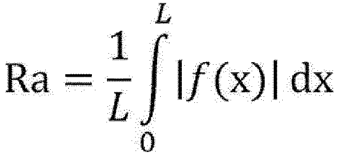
- The method of manufacturing a formed body for an electrode according to the present disclosure has the third step of discharging the electrode material in the shape retaining member onto a support from the opening portion L while relatively moving the opening portion L of the shape retaining member and the support along a short side direction of the opening portion L, to form a film of the electrode material on the support after the second step.
- Here, the electrode material discharged from the opening portion L is supplied onto the support while passing through a void between the end portion X and the support.
- Hereinafter, a specific embodiment of the third step will be described with reference to the drawing.
- Here, the third step will be described using
Fig. 4 . Here,Fig. 4 is a schematic diagram illustrating an embodiment of the third step in the method of manufacturing a formed body for an electrode according to the present disclosure. -
Fig. 4 shows an aspect in which theelectrode material 20 is discharged onto thesupport 30 transported in a direction of the arrow A from theopening portion L 14 of theshape retaining member 10, and anelectrode material film 22 of theelectrode material 20 is formed on thesupport 30. - The operation of forming the
electrode material film 22 will be described in detail. - As shown in
Fig. 4 , at theopening portion L 14 of theshape retaining member 10, one end portion (that is, a side)X 10x of the pair of long side end portions of theopening portion L 14 is present closer to the otheropening portion M 12 than the other end portion (that is, a side)Y 10y of the pair of long side end portions, and a void with a distance T2 is formed between theend portion X 10x and the support. - Therefore, the
electrode material 20 discharged from theopening portion L 14 of theshape retaining member 10 is transported to the void formed between theend portion X 10x and the support as the support is moved in the direction of the arrow A. The transportedelectrode material 20 is regulated in film thickness by a film thickness regulating force acting while passing through the void, and anelectrode material film 22 having a thickness that is the same as the size of the void, that is, the distance T2 is formed. - In the method of manufacturing a formed body for an electrode according to the present disclosure, as described above, width T1>distance T2 is established, and thus it is thought that the
electrode material 20 is compacted by a pressure applied by the above-described film thickness regulating force, and the density distribution is further reduced. - In
Fig. 4 , the smaller the distance between theend portion Y 10y of theopening portion L 14 of theshape retaining member 10 and thesupport 30, the better from the viewpoint that theelectrode material 20 is efficiently moved to the void formed between theend portion X 10x and thesupport 30. The distance is, for example, preferably 10 µm or less, and more preferably 5 µm or less. - In addition, in a case where the distance between the
end portion Y 10y and thesupport 30 is too small, theend portion Y 10y and thesupport 30 may be brought into contact with each other, and thesupport 30 may be damaged. Therefore, the lower limit is preferably, for example, 1 µm. - In the
shape retaining member 10 shown inFigs. 1 to 4 , theend portion X 10x of the opening portion L is formed from the skeleton of theshape retaining member 10, but is not limited to this configuration as long as the above-described distance T2 is obtained. For example, the shape retaining member may have another member (for example, roll member) at a position corresponding to the end portion X. -
Figs. 1 to 4 show the aspect in which thesupport 30 is transported in the direction of the arrow A with respect to the fixedshape retaining member 10, but the present disclosure is not limited thereto. - In the method of manufacturing a formed body for an electrode according to the present disclosure, the opening portion L of the shape retaining member and the support may be relatively moved along the short side direction of the opening portion L. In addition to the above aspect, an aspect in which the shape retaining member is moved with respect to the fixed support, or an aspect in which both the support and the shape retaining member are moved may be employed.
- In order to continuously form the
electrode material film 22, an aspect in which a long support is used and moved with respect to the fixed shape retaining member is preferable. - Here, the transport mechanism for the support is not limited, and known transport units can be used. Examples thereof include a belt conveyor, a linear motion guide, and a cross roller table.
- The support used in the third step has a larger area than the opening portion L of the shape retaining member since it is required to receive the electrode material discharged from the opening portion L of the shape retaining member.
- In particular, a long support is preferably used from the viewpoint of continuously forming the electrode material film. In a case of the long support, its width is preferably larger than the width T3 in the long side direction of the opening portion L of the shape retaining member, and specifically, the width is preferably 0.5% or more (more preferably 2% or more) larger than T3.
- The support may be appropriately selected according to the post-step to be performed on the formed body for an electrode manufactured through the third step.
- Preferable specific examples of the support include a release material and a collector.
- Examples of the release material as an example of the support include release paper (for example, release paper manufactured by LINTEC Corporation), surface-treated metals (for example, aluminum and stainless steel (generally referred to as "SUS"), films having a surface layer, and paper having a surface layer. Among these, release paper is preferable.
- The collector as an example of the support is not particularly limited, and known collectors (positive electrode collector and negative electrode collector) can be used.
- Examples of the positive electrode collector include aluminum, aluminum alloys, stainless steel, nickel, and titanium. The positive electrode collector is preferably aluminum or an aluminum alloy. The positive electrode collector is also preferably aluminum or stainless steel having a surface with a coating layer containing carbon, nickel, titanium, or silver.
- Examples of the negative electrode collector include aluminum, copper, copper alloys, stainless steel, nickel, and titanium. The negative electrode collector is preferably aluminum, copper, a copper alloy, or stainless steel, and more preferably copper or a copper alloy. The negative electrode collector is also preferably aluminum, copper, a copper alloy, or stainless steel having a surface with a coating layer containing carbon, nickel, titanium, or silver.
- As the collector, aluminum foil or copper foil is preferable. Aluminum foil is usually used as a collector at the positive electrode. Copper foil is usually used as a collector at the negative electrode.
- The shape of the support is preferably a flat plate shape, a film shape, or a sheet shape from the viewpoint of transportability and the like.
- The average thickness of the support is preferably 5 µm or more, more preferably 10 µm or more, and particularly preferably 20 µm or more from the viewpoint of transportability and the like.
- The average thickness is preferably 500 µm or less, more preferably 300 µm or less, and particularly preferably 200 µm or less from the viewpoint of flexibility and lightweight property.
- The average thickness of the support is an arithmetic average of the thicknesses measured at three points by cross-section observation. In the cross-section observation, known microscopes (for example, a scanning electron microscope) can be used.
- The size of the support is not limited, and may be determined according to the size of a formed body for an electrode to be manufactured, the sizes of various members used in the manufacturing process, and the like.
- The method of manufacturing a formed body for an electrode according to the present disclosure may optionally have the fourth step of regulating the film thickness of the electrode material film formed on the support after the third step.
- By regulating the film thickness of the electrode material film, the in-plane uniformity of the mass distribution of a formed body for an electrode can be further increased.
- The fourth step will be described with reference to
Fig. 5 . Here,Fig. 5 is a schematic diagram illustrating the fourth step in the method of manufacturing a formed body for an electrode according to the present disclosure. - As shown in
Fig. 5 , the film thickness of theelectrode material film 22 formed on thesupport 30 is regulated by a regulatingroll 40. - Examples of the regulating unit used in the fourth step include a roll member such as a regulating roll (for example, also referred to as a squeegee roll), a scraper, and a plate-shaped member (for example, a squeegee).
- In the present disclosure, in the regulation of the amount, density distribution, and the like of the electrode material, in addition to the above-described regulating unit, a vibrating unit vibrating the electrode material may be used in combination.
- By providing the vibrating unit, the amount, density distribution, and the like of the electrode material are easily controlled.
- Examples of the vibrating unit include a general vibrator.
- The method of manufacturing a formed body for an electrode according to the present disclosure may have the fifth step of placing a protective member on the formed electrode material film after the third step or the fourth step.
- By placing the protective member on the electrode material film, it is possible to suppress the scattering or peeling of a part of the electrode material from the electrode material film, and it is possible to further improve workability and transportability in the post step.
- The protective member may be a member that protects the electrode material from scattering, peeling, and the like. Specifically, for example, a release material or a collector is preferable as in the case of the above-described support. The release material and the collector used as the protective member are the same as those used as the support, and preferable aspects are also the same.
- In the method of manufacturing a formed body for an electrode according to the present disclosure, in a case where both the support and the protective member are not collectors, and for example, a collector is used as the support, a release material is selected as the protective member.
- The method of manufacturing a formed body for an electrode according to the present disclosure may include the following other steps.
- For example, a sixth step of pressurizing the electrode material film, a seventh step of transferring the electrode material film onto the protective member placed in the fifth step, and the like may be included.
- The method of manufacturing a formed body for an electrode according to the present disclosure may have the sixth step of pressurizing the electrode material film after the third step, the fourth step, or the fifth step.
- In a case where the method of manufacturing a formed body for an electrode according to the present disclosure includes the forming step, the density of the electrode material can be increased, and the density can be made uniform.
- Examples of the pressurizing unit used in the sixth step include a pressurizing roll pair and a press machine.
- In a case where the electrode material is pressurized, the pressure is preferably 1 MPa to 1 GPa, more preferably 5 MPa to 500 MPa, and particularly preferably 10 MPa to 300 MPa.
- In the sixth step, the electrode material may be pressurized in a stepwise manner using a plurality of pressurizing units (for example, a pressurizing roll pair). By pressurizing the electrode material in a stepwise manner using a plurality of pressurizing units, the density distribution of the electrode material can be made more uniform.
- For example, using a plurality of pressurizing roll pairs in which a gap between the rolls is adjusted to be narrower in a stepwise manner, the electrode material can be pressurized in a stepwise manner.
- In the sixth step, the pressurizing unit and the electrode material (specifically, the first support on which the electrode material is supplied) are preferably relatively moved.
- In the present disclosure, "relatively moving the pressurizing unit and the electrode material" includes moving the pressurizing unit with respect to the electrode material in one direction, moving the electrode material with respect to the pressurizing unit in one direction, and respectively moving the pressurizing unit and the electrode material in one direction. Among these, moving the electrode material with respect to the pressurizing unit in one direction is preferable as the method of "relatively moving the pressurizing unit and the electrode material".
- The unit that moves the electrode material (specifically, the support on which the electrode material film is formed) is not limited, and known transport units can be used. Examples thereof include a belt conveyor, a linear motion guide, and a cross roller table.
- In the sixth step, for example, the electrode material heated at 30°C to 100°C may be pressurized from the viewpoint of an improvement in formability.
- In the method of manufacturing a formed body for an electrode according to the present disclosure, the seventh step of transferring the electrode material onto the protective member may be performed after the fifth step.
- In the seventh step, after the laminate in which the electrode material film is sandwiched between the support and the protective member is formed through the fifth step, the laminate is inverted upside down to transfer the electrode material onto the protective member.
- In the seventh step, in a case where the protective member is a collector, the electrode material is transferred onto the protective member, and a formed body for an electrode with a collector is obtained.
- A formed body for an electrode obtained by the method of manufacturing a formed body for an electrode according to the present disclosure is excellent in in-plane uniformity of a density, and can thus be used as various electrodes.
- The formed body for an electrode is preferably a formed body for an electrode for an all-solid state secondary battery.
- The shape of the formed body for an electrode is not limited, and may be appropriately determined depending on the intended use. The shape of the formed body for an electrode is preferably a flat plate shape.
- The average thickness of the formed body for an electrode is preferably 0.01 mm to 2 mm, more preferably 0.05 mm to 1.5 mm, and particularly preferably 0.1 mm to 1 mm from the viewpoint of an improvement in battery performance (for example, discharge capacity and output characteristics).
- The average thickness of the formed body for an electrode is measured in the same manner as the average thickness of the first support.
- Hereinafter, the present disclosure will be described in detail with examples, but is not limited thereto.
- A sulfide-based inorganic solid electrolyte was prepared with reference to T. Ohtomo, A. Hayashi, M. Tatsumisago, Y. Tsuchida, S. Hama, K. Kawamoto, Journal of Power Sources, 233, (2013), pp. 231 to 235, and A. Hayashi, S. Hama, H. Morimoto, M. Tatsumisago, T. Minami, Chem. Lett., (2001), pp 872 to 873.
- Specifically, in a glove box under an argon atmosphere (dew point: -70°C), 2.42 g of lithium sulfide (Li2S, manufactured by Sigma-Aldrich Inc., purity: >99.98%) and 3.9 g of diphosphorus pentasulfide (P2S5, manufactured by Sigma-Aldrich Inc., purity: >99%) were respectively weighed, and then the lithium sulfide and the diphosphorus pentasulfide were mixed for 5 minutes using an agate mortar. The molar ratio of Li2S to P2S5 (Li2S:P2S5) was 75:25.
- 66 zirconia beads having a diameter of 5 mm were put in a 45 mL zirconia container (manufactured by Fritsch GmbH). Then, the entire amount of the mixture of the lithium sulfide and the diphosphorus pentasulfide was put therein, and then the container was completely sealed under an argon atmosphere. The container was mounted on a planetary ball mill P-7 (trade name) manufactured by Fritsch GmbH, and mechanical milling was performed for 20 hours at a temperature of 25°C and a rotation speed of 510 rpm (revolutions per minute) to obtain 6.2 g of a yellow powder of a sulfide-based solid electrolyte (Li-P-S-based glass). The above steps were repeated 10 times, and 62 g of a sulfide-based solid electrolyte was obtained.
- 180 zirconia beads having a diameter of 5 mm were put in a 45 mL zirconia container (manufactured by Fritsch GmbH), and then 3.0 g of the prepared Li-P-S-based glass was put therein. The container was mounted on a planetary ball mill P-7 manufactured by Fritsch GmbH, and mixing was performed for 2 hours at a temperature of 25°C and a rotation speed of 300 rpm. Next, 6.8 g of LCO (LiCoO2, manufactured by Nippon Chemical Industrial CO., LTD.) as an active material and Li-100 (0.2 g) manufactured by Denka Company as a conductive auxiliary agent were put in the container. Then, the container was mounted on the planetary ball mill P-7, and mixing was performed for 10 minutes at a temperature of 25°C and a rotation speed of 100 rpm to obtain a particulate electrode material (P-1) for a positive electrode. The above steps were repeated 100 times, and a required amount of an electrode material (P-1) for a positive electrode was obtained.
- A bulk density D1 of the obtained electrode material (P-1) for a positive electrode, measured by the method described above, was 0.3 g/cm3.
- A
shape retaining member 10 as shown inFig. 1 was prepared. - That is, the
shape retaining member 10 having a rectangular tubular shape with rectangular opening portions, in which oneend portion X 10x of a pair of long side end portions of oneopening portion L 14 was present closer to the otheropening portion M 12 than the otherend portion Y 10y of the pair of long side end portions was produced. - Here, in the
shape retaining member 10, a distance between theend portion X 10x and theopening portion M 12 was 49.50 mm, and T4 from theend portion Y 10y to the opening portion M was 50.00 mm. In addition, a width T1 of the opening portion L in a short side direction was 15 mm, and a width T3 of the opening portion L in a long side direction was 180 mm. - Subsequently, a surface layer was formed on an inner peripheral surface of the shape retaining member by the following method.
- First, an undercoat layer was formed on the inner peripheral surface of the shape retaining member by the method described above, and then fluororesin coating was performed using NF-004 (main material: FEP) manufactured by NIPPON FUSSO CO., LTD. to form a surface layer.
- A positive electrode sheet was produced as follows by the method shown in
Fig. 1 . - The electrode material (P-1) for a positive electrode was put in four screw feeders (powder measuring feeders (screw type) manufactured by AS ONE Corporation, PSF-100SA) placed in parallel. A
pressure feed unit 50 as shown inFig. 1 was provided in a lower portion of the screw feeder, and the electrode material (P-1) for a positive electrode was supplied to theopening portion M 14 of theshape retaining member 10 through thepressure feed unit 50. - Both the pair of
rolls pressure feed unit 50 were stainless steel roll members having an outer diameter of 50 mm, a distance between the rolls was 15 mm, and the rotation speed of the rolls was 5 m/min. - In the lower portion of the
pressure feed unit 50, theshape retaining member 10 was placed with theopening portion L 14 facing down so that an axial direction thereof was parallel to a direction of gravitational force (direction of arrow G inFig. 1 ). More specifically, theshape retaining member 10 was placed with theopening portion L 14 facing down so that a void of 5 µm was formed between theend portion Y 10y of theshape retaining member 10 and thesupport 30, and a distance T2 between theend portion X 10x of theshape retaining member 10 and thesupport 30 was 0.5 mm (500 µm) by being adjusted using a taper gauge or the like. - That is, the distance T2 between the
end portion X 10x of theshape retaining member 10 and thesupport 30 was 0.5 mm (500 µm), and the distance between theend portion Y 10y of theshape retaining member 10 and thesupport 30 was 5 µm. - After the
support 30 was transported in a direction of the arrow A at a transportation speed of 5 m/min and reached a point below theopening portion L 14, the electrode material (P-1) for a positive electrode was pressure-fed into theshape retaining member 10 by thepressure feed unit 50, and discharged onto thesupport 30 through theshape retaining member 10. - Here, the
support 30 was release paper: release paper manufactured by LINTEC Corporation (glassine direct type, average thickness: 60 µm, width: 200 mm, length: 300 mm). - A bulk density D2 of the electrode material at the
opening portion L 14 of theshape retaining member 10, measured as described above, was 1.2 g/cm3. - Through the above procedure, a powder sheet (positive electrode sheet) having a thickness of 500 µm, a width of 180 mm, and a length of 290 mm was obtained on the
support 30. - Powder sheets were produced in the same manner as in Example 1, except that the shape of the shape retaining member was appropriately changed, and the width T1 and the distance T2 were changed as shown in the following Table 1.
- Powder sheets were produced in the same manner as in Examples 1 to 3, except that the shape of the shape retaining member was appropriately changed, the length (height) T4 from the
end portion Y 10y of theshape retaining member 10 to the opening portion M was 400 mm, the width T1 and the distance T2 were changed as shown in the following Table 1, and thepressure feed unit 50 was not used. - More specifically, the
support 30 was placed below theopening portion L 14, the electrode material (P-1) for a positive electrode was put in theshape retaining member 10 with a spatula so as to fill the whole volume of the shape retaining member, a weight of 500 g or 3,000 g was placed on the electrode material (P-1) for a positive electrode, and then thesupport 30 was transported in the direction of the arrow A at a transportation speed of 5 m/min to discharge the electrode material (P-1) for a positive electrode onto thesupport 30. - A powder sheet was produced by the same procedure as in Example 1, except that an electrode material (P-2) for a positive electrode prepared by kneading the electrode material (P-1) for a positive electrode and an electrolytic solution was used. The content of the electrolytic solution was 30 mass% with respect to the total mass of the electrode material (P-2) for a positive electrode. A lithium hexafluorophosphate solution (1.0 M LiPF6 in EC/EMC=50/50 (v/v)) manufactured by Sigma-Aldrich Inc. was used as the electrolytic solution. "EC" means ethylene carbonate. "EMC" means ethyl methyl carbonate.
- A powder sheet was produced by the same procedure as in Example 6, except that the electrode material (P-2) for a positive electrode was used.
- A powder sheet (positive electrode sheet) was produced in the same manner as in Example 1, except that the
support 30 was placed below theopening portion L 14, the electrode material (P-1) for a positive electrode was put in theshape retaining member 10 with a spatula so as to fill the whole volume of the shape retaining member, and then thesupport 30 was transported in the direction of the arrow A at a transportation speed of 5 m/min. - A powder sheet (positive electrode sheet) was produced in the same manner as in Example 1, except that the
shape retaining member 10 was not used. - That is, the electrode material pressure-fed by the pair of
rolls pressure feed unit 50 was supplied onto the support as it was, and the powder sheet was produced. - A powder sheet was produced in the same manner as in Example 1, except that the shape of the
shape retaining member 10 was appropriately changed, and the width T1 and the distance T2 were changed as shown in the following Table 1. - Test pieces having a size of 1 cm2 were cut out from 80 places ([8 places in width direction] × [10 places in length direction]) in the powder sheet. A frame-shaped Thomson blade in which the area inside the frame per frame was adjusted to 1 cm2 was used to cut out the test piece. Next, the mass of each of the test pieces cut out from the total 80 places in the powder sheet was measured. From the mass of the test pieces, a mass standard deviation (σ) of the whole powder sheet was obtained, and uniformity of the mass distribution was evaluated according to the following criteria. Of the following criteria, A, B, and C were accepted.
-
- A: 0%≤σ<1%
- B: 1%≤σ<3%
- C: 3%≤σ<5%
- D: 5%≤σ<10%
- E: 10%≤σ
-
[Table 1] Electrode Material Conditions Presence or Absence of Pressure Feed Unit Mass of Weight [g] Mass Distribution σ [%] Bulk Density D1 [g/cm3] Bulk Density D2 [g/cm3] D2/D1 Width T1 [mm] Distance T2 [mm] T1/T2 Examples 1 (P-1) 0.3 1.2 4 15 0.5 30 Presence - 0.8 (A) 2 (P-1) 0.3 1.2 4 1.5 0.5 3 Presence - 1.4 (B) 3 (P-1) 0.3 1.2 4 20 0.2 100 Presence - 1.8 (B) 4 (P-1) 0.3 1.2 4 15 1.0 15 Presence - 1.6 (B) 5 (P-1) 0.3 1.2 4 15 0.1 150 Presence - 1.9 (B) 6 (P-1) 0.3 0.6 2 15 0.5 30 Absence 500 2.8 (B) 7 (P-1) 0.3 0.6 2 1.5 0.5 3 Absence 500 3.2 (C) 8 (P-1) 0.3 0.6 2 20 0.2 100 Absence 500 3.4 (C) 9 (P-1) 0.3 1.8 6 15 0.5 30 Absence 3000 1.8 (B) 10 (P-1) 0.3 1.8 6 1.5 0.5 3 Absence 3000 2.2 (B) 11 (P-1) 0.3 1.8 6 20 0.2 100 Absence 3000 2.3 (B) 12 (P-2) 0.3 1.2 4 15 0.5 30 Presence - 2.5 (B) 13 (P-2) 0.3 0.6 2 15 0.5 30 Absence 500 3.6 (C) Comparative Examples 1 (P-1) 0.3 0.3 1 5 0.5 10 Presence - 7.0 (D) 2 (P-1) 0.3 1.2 4 - - - Presence - 15.0 (E) 3 (P-1) 0.3 1.2 4 1.0 1.0 1 Presence - 6.5 (D) - From Table 1, it has been found that Examples 1 to 13 are higher in uniformity of the mass distribution than Comparative Examples 1 to 3.
-
- 10:
- shape retaining member
- 10x:
- end portion X
- 10y:
- end portion Y
- 12:
- opening portion M
- 14:
- opening portion L
- 20:
- electrode material
- 22:
- electrode material film
- 30:
- support
- 40:
- regulating roll
- 50:
- pressure feed unit
- 50a:
- roll member
- 50b:
- roll member
- 52:
- container
- A:
- transport direction of
support 30 - B:
- axial direction of
shape retaining member 10 - G:
- direction of gravitational force
- a:
- rotation direction of
roll member 50a - The entire disclosure of
JP2019-149867 filed on August 19, 2019
Claims (8)
- A method of manufacturing a formed body for an electrode comprising in order:a first step of preparing an electrode material containing an electrode active material;a second step of placing a shape retaining member having a rectangular tubular shape with rectangular opening portions, in which one end portion X of a pair of long side end portions of one opening portion L is present closer to the other opening portion M than the other end portion Y of the pair of long side end portions, with the opening portion L facing down so that an axial direction of the shape retaining member is parallel to a direction of gravitational force, and supplying the electrode material into the shape retaining member from the opening portion M of the shape retaining member; anda third step of discharging the electrode material in the shape retaining member onto a support from the opening portion L while relatively moving the opening portion L of the shape retaining member and the support along a short side direction of the opening portion L, to form a film of the electrode material on the support,wherein in a case where a bulk density of the electrode material prepared in the first step is denoted by D1 [g/cm3] and a bulk density of the electrode material at the opening portion L of the shape retaining member is denoted by D2 [g/cm3], bulk density D2/bulk density D1=1. 1 to 30 is satisfied, andin a case where a width of the opening portion L in the short side direction is denoted by T1 [mm] and a distance between the end portion X of the opening portion L and the support is denoted by T2 [mm], a relationship of width T1>distance T2 is satisfied.
- The method of manufacturing a formed body for an electrode according to claim 1, wherein the width T1 and the distance T2 satisfy width Ti/distance T2=1.5 to 500.
- The method of manufacturing a formed body for an electrode according to claim 1 or 2, wherein the distance T2 is 0.1 mm to 1.0 mm.
- The method of manufacturing a formed body for an electrode according to any one of claims 1 to 3,
wherein the width T1 is 1.5 mm to 50 mm. - The method of manufacturing a formed body for an electrode according to any one of claims 1 to 4,
wherein the bulk density D2 is 0.55 g/cm3 to 3.0 g/cm3. - The method of manufacturing a formed body for an electrode according to any one of claims 1 to 5,
wherein the bulk density D1 is 0.1 g/cm3 to 0.5 g/cm3. - The method of manufacturing a formed body for an electrode according to any one of claims 1 to 6,
wherein the bulk density D1 and the bulk density D2 satisfy bulk density D2/bulk density D1=1.5 to 20. - The method of manufacturing a formed body for an electrode according to any one of claims 1 to 7,
wherein in the second step, the electrode material is pressure-fed into the shape retaining member from the opening portion M of the shape retaining member by a pressure feed unit to supply the electrode material into the shape retaining member from the opening portion M of the shape retaining member.
Applications Claiming Priority (2)
| Application Number | Priority Date | Filing Date | Title |
|---|---|---|---|
| JP2019149867 | 2019-08-19 | ||
| PCT/JP2020/031153 WO2021033689A1 (en) | 2019-08-19 | 2020-08-18 | Electrode moulded body production method |
Publications (2)
| Publication Number | Publication Date |
|---|---|
| EP3982438A1 true EP3982438A1 (en) | 2022-04-13 |
| EP3982438A4 EP3982438A4 (en) | 2022-09-14 |
Family
ID=74661174
Family Applications (1)
| Application Number | Title | Priority Date | Filing Date |
|---|---|---|---|
| EP20854716.6A Pending EP3982438A4 (en) | 2019-08-19 | 2020-08-18 | Electrode moulded body production method |
Country Status (5)
| Country | Link |
|---|---|
| US (1) | US11605805B2 (en) |
| EP (1) | EP3982438A4 (en) |
| JP (1) | JP7242868B2 (en) |
| CN (1) | CN114128007B (en) |
| WO (1) | WO2021033689A1 (en) |
Cited By (2)
| Publication number | Priority date | Publication date | Assignee | Title |
|---|---|---|---|---|
| EP4020613A4 (en) * | 2019-08-19 | 2023-03-29 | FUJIFILM Corporation | Method for producing molded body for electrodes |
| EP4564467A4 (en) * | 2022-07-28 | 2025-11-26 | Fujifilm Corp | METHOD FOR PRODUCE AN ELECTRODE MATERIAL, METHOD FOR PRODUCE A BATTERY ELECTRODE AND METHOD FOR PRODUCE A BATTERY |
Families Citing this family (3)
| Publication number | Priority date | Publication date | Assignee | Title |
|---|---|---|---|---|
| JP7538946B2 (en) * | 2021-05-25 | 2024-08-22 | エルジー エナジー ソリューション リミテッド | Apparatus for manufacturing film-type positive electrode, manufacturing method thereof, and lithium secondary battery, battery module, and battery pack including the same |
| CN119631192A (en) * | 2022-07-28 | 2025-03-14 | 富士胶片株式会社 | Method for producing formed body for sheet-shaped electrode |
| EP4697407A1 (en) | 2023-04-13 | 2026-02-18 | FUJIFILM Corporation | Method of producing electrode layer |
Family Cites Families (31)
| Publication number | Priority date | Publication date | Assignee | Title |
|---|---|---|---|---|
| JPS62109997A (en) | 1985-11-07 | 1987-05-21 | Kobe Steel Ltd | Pretreatment of valve metal before anodic oxidation |
| JP3140678B2 (en) * | 1996-03-12 | 2001-03-05 | 古河電池株式会社 | Automatic filling device for paste active material into storage battery electrode substrate |
| JP3614990B2 (en) * | 1996-08-08 | 2005-01-26 | 株式会社東芝 | Sheet electrode manufacturing method and non-aqueous electrolyte battery |
| CA2207801C (en) | 1996-06-19 | 2004-03-30 | Hideki Kaido | Nonaqueous electrolyte battery |
| JPH10340727A (en) * | 1997-06-04 | 1998-12-22 | Matsushita Electric Ind Co Ltd | Manufacture of battery electrode and battery |
| TWI237287B (en) * | 2002-04-24 | 2005-08-01 | Fujitsu Hitachi Plasma Display | Fluorescent layer forming apparatus |
| JPWO2011052126A1 (en) * | 2009-10-28 | 2013-03-14 | パナソニック株式会社 | Electrode, secondary battery, and method for manufacturing secondary battery |
| JP5719516B2 (en) * | 2010-02-08 | 2015-05-20 | 富士フイルム株式会社 | Casting apparatus and method, and solution casting method |
| JP2013077560A (en) * | 2011-09-14 | 2013-04-25 | Nippon Zeon Co Ltd | Method for manufacturing electrode for electrochemical element |
| US20140342225A1 (en) | 2011-09-14 | 2014-11-20 | Zeon Corporation | Electrode for electrochemical device |
| KR101511732B1 (en) | 2012-04-10 | 2015-04-13 | 주식회사 엘지화학 | Electrode having porous coating layer and electrochemical device containing the same |
| JP2014102991A (en) * | 2012-11-20 | 2014-06-05 | Toyota Industries Corp | Electrode manufacturing method and electrode manufacturing device |
| JP2014164982A (en) | 2013-02-25 | 2014-09-08 | Dainippon Screen Mfg Co Ltd | Electrode for battery, battery, method of manufacturing electrode for battery, and apparatus of manufacturing electrode for battery |
| JP6231292B2 (en) | 2013-03-29 | 2017-11-15 | トヨタ自動車株式会社 | Powder coating apparatus and electrode manufacturing method using the same |
| JP6108166B2 (en) * | 2013-06-28 | 2017-04-05 | トヨタ自動車株式会社 | Secondary battery electrode |
| KR20180069137A (en) | 2013-09-25 | 2018-06-22 | 후지필름 가부시키가이샤 | Solid electrolyte composition, electrode sheet for batteries using same and all-solid-state secondary battery |
| US9859560B2 (en) * | 2014-06-04 | 2018-01-02 | Quantumscape Corporation | Electrode materials with mixed particle sizes |
| JP6067636B2 (en) | 2014-09-12 | 2017-01-25 | トヨタ自動車株式会社 | Method for producing electrode for lithium ion secondary battery |
| JP6283917B2 (en) | 2014-09-18 | 2018-02-28 | パナソニックIpマネジメント株式会社 | Coating film manufacturing method and coating film manufacturing apparatus |
| US10396350B2 (en) | 2015-01-05 | 2019-08-27 | Zeon Corporation | Method for manufacturing electrode for lithium ion battery |
| JP5999237B2 (en) | 2015-09-04 | 2016-09-28 | 日本ゼオン株式会社 | Powder rolling apparatus and rolled sheet manufacturing method |
| JP6811007B2 (en) | 2015-09-09 | 2021-01-13 | 三洋化成工業株式会社 | Method for manufacturing resin for coating non-aqueous secondary battery active material, coating active material for non-aqueous secondary battery, and coating active material for non-aqueous secondary battery |
| JP2017104784A (en) | 2015-12-08 | 2017-06-15 | トヨタ自動車株式会社 | Granule sheet manufacturing equipment |
| JP6607959B2 (en) | 2015-12-16 | 2019-11-20 | 富士フイルム株式会社 | Electrode material, electrode sheet for all-solid-state secondary battery, all-solid-state secondary battery, electrode sheet for all-solid-state secondary battery, and method for producing all-solid-state secondary battery |
| US11040368B2 (en) * | 2017-02-08 | 2021-06-22 | Toyota Jidosha Kabushiki Kaisha | Manufacturing method of paste-layer-attached sheet and coating applicator |
| JP6449390B1 (en) * | 2017-08-09 | 2019-01-09 | 住友理工株式会社 | Method for producing conductive film |
| JP7022539B2 (en) | 2017-09-07 | 2022-02-18 | 三洋化成工業株式会社 | Method for manufacturing electrodes for lithium-ion batteries and equipment for manufacturing electrodes for lithium-ion batteries |
| JP6948903B2 (en) * | 2017-09-29 | 2021-10-13 | 三洋化成工業株式会社 | Method for manufacturing electrodes for lithium-ion batteries and filling equipment for electrode compositions |
| JP6915566B2 (en) | 2018-02-26 | 2021-08-04 | オムロン株式会社 | Power converter and power conversion system |
| JP2020087856A (en) * | 2018-11-30 | 2020-06-04 | 株式会社豊田自動織機 | Electrode for lithium ion secondary battery and manufacturing installation of electrode for lithium ion secondary battery |
| KR102707228B1 (en) * | 2020-10-30 | 2024-09-20 | 주식회사 엘지에너지솔루션 | Die for coating insulating liquid and method for coating insulating liquid |
-
2020
- 2020-08-18 WO PCT/JP2020/031153 patent/WO2021033689A1/en not_active Ceased
- 2020-08-18 EP EP20854716.6A patent/EP3982438A4/en active Pending
- 2020-08-18 CN CN202080051206.0A patent/CN114128007B/en active Active
- 2020-08-18 JP JP2021540951A patent/JP7242868B2/en active Active
-
2021
- 2021-12-28 US US17/563,092 patent/US11605805B2/en active Active
Cited By (3)
| Publication number | Priority date | Publication date | Assignee | Title |
|---|---|---|---|---|
| EP4020613A4 (en) * | 2019-08-19 | 2023-03-29 | FUJIFILM Corporation | Method for producing molded body for electrodes |
| US12288869B2 (en) | 2019-08-19 | 2025-04-29 | Fujifilm Corporation | Method of manufacturing formed body for electrode |
| EP4564467A4 (en) * | 2022-07-28 | 2025-11-26 | Fujifilm Corp | METHOD FOR PRODUCE AN ELECTRODE MATERIAL, METHOD FOR PRODUCE A BATTERY ELECTRODE AND METHOD FOR PRODUCE A BATTERY |
Also Published As
| Publication number | Publication date |
|---|---|
| JPWO2021033689A1 (en) | 2021-02-25 |
| CN114128007A (en) | 2022-03-01 |
| WO2021033689A1 (en) | 2021-02-25 |
| US20220123275A1 (en) | 2022-04-21 |
| CN114128007B (en) | 2024-07-23 |
| US11605805B2 (en) | 2023-03-14 |
| JP7242868B2 (en) | 2023-03-20 |
| EP3982438A4 (en) | 2022-09-14 |
Similar Documents
| Publication | Publication Date | Title |
|---|---|---|
| US12243999B2 (en) | Method of manufacturing formed body for electrode | |
| US11605805B2 (en) | Method of manufacturing formed body for electrode | |
| EP3780239A1 (en) | Fully solid-state secondary battery and method of manufacturing same | |
| EP3883035A1 (en) | Solid electrolyte and battery using same | |
| EP4404303A1 (en) | Coated active material, method for producing coated active material, positive electrode material and battery | |
| US12199263B2 (en) | Method of manufacturing formed body for electrode | |
| Kubanska et al. | Effect of composite electrode thickness on the electrochemical performances of all-solid-state li-ion batteries | |
| JP7572525B2 (en) | Method for producing electrode molded body | |
| US20240105988A1 (en) | All-solid battery and method of manufacturing the same | |
| US20250183252A1 (en) | Manufacturing method of molded body for sheet-like electrode | |
| US12288869B2 (en) | Method of manufacturing formed body for electrode | |
| US12199264B2 (en) | Method of manufacturing formed body for electrode | |
| US20250309357A1 (en) | Solid-state secondary battery, and method of preparing charging the solid-state secondary battery | |
| US20260066262A1 (en) | Solid electrolyte-electrode assembly, methods for making, and an all-solid-state battery thereof | |
| WO2026071262A1 (en) | Method for manufacturing quasi-solid-state battery |
Legal Events
| Date | Code | Title | Description |
|---|---|---|---|
| STAA | Information on the status of an ep patent application or granted ep patent |
Free format text: STATUS: THE INTERNATIONAL PUBLICATION HAS BEEN MADE |
|
| PUAI | Public reference made under article 153(3) epc to a published international application that has entered the european phase |
Free format text: ORIGINAL CODE: 0009012 |
|
| STAA | Information on the status of an ep patent application or granted ep patent |
Free format text: STATUS: REQUEST FOR EXAMINATION WAS MADE |
|
| 17P | Request for examination filed |
Effective date: 20220104 |
|
| AK | Designated contracting states |
Kind code of ref document: A1 Designated state(s): AL AT BE BG CH CY CZ DE DK EE ES FI FR GB GR HR HU IE IS IT LI LT LU LV MC MK MT NL NO PL PT RO RS SE SI SK SM TR |
|
| A4 | Supplementary search report drawn up and despatched |
Effective date: 20220818 |
|
| RIC1 | Information provided on ipc code assigned before grant |
Ipc: H01M 4/02 20060101ALI20220811BHEP Ipc: H01M 4/139 20100101ALI20220811BHEP Ipc: H01M 4/04 20060101AFI20220811BHEP |
|
| DAV | Request for validation of the european patent (deleted) | ||
| DAX | Request for extension of the european patent (deleted) |