EP3982428A1 - Light source module and lighting device comprising same - Google Patents
Light source module and lighting device comprising same Download PDFInfo
- Publication number
- EP3982428A1 EP3982428A1 EP20819278.1A EP20819278A EP3982428A1 EP 3982428 A1 EP3982428 A1 EP 3982428A1 EP 20819278 A EP20819278 A EP 20819278A EP 3982428 A1 EP3982428 A1 EP 3982428A1
- Authority
- EP
- European Patent Office
- Prior art keywords
- light
- peak
- fluorescent powder
- source module
- light source
- Prior art date
- Legal status (The legal status is an assumption and is not a legal conclusion. Google has not performed a legal analysis and makes no representation as to the accuracy of the status listed.)
- Granted
Links
Images




Classifications
-
- H—ELECTRICITY
- H10—SEMICONDUCTOR DEVICES; ELECTRIC SOLID-STATE DEVICES NOT OTHERWISE PROVIDED FOR
- H10H—INORGANIC LIGHT-EMITTING SEMICONDUCTOR DEVICES HAVING POTENTIAL BARRIERS
- H10H20/00—Individual inorganic light-emitting semiconductor devices having potential barriers, e.g. light-emitting diodes [LED]
- H10H20/80—Constructional details
- H10H20/85—Packages
- H10H20/851—Wavelength conversion means
- H10H20/8511—Wavelength conversion means characterised by their material, e.g. binder
- H10H20/8512—Wavelength conversion materials
- H10H20/8513—Wavelength conversion materials having two or more wavelength conversion materials
-
- F—MECHANICAL ENGINEERING; LIGHTING; HEATING; WEAPONS; BLASTING
- F21—LIGHTING
- F21S—NON-PORTABLE LIGHTING DEVICES; SYSTEMS THEREOF; VEHICLE LIGHTING DEVICES SPECIALLY ADAPTED FOR VEHICLE EXTERIORS
- F21S8/00—Lighting devices intended for fixed installation
-
- F—MECHANICAL ENGINEERING; LIGHTING; HEATING; WEAPONS; BLASTING
- F21—LIGHTING
- F21Y—INDEXING SCHEME ASSOCIATED WITH SUBCLASSES F21K, F21L, F21S and F21V, RELATING TO THE FORM OR THE KIND OF THE LIGHT SOURCES OR OF THE COLOUR OF THE LIGHT EMITTED
- F21Y2103/00—Elongate light sources, e.g. fluorescent tubes
- F21Y2103/10—Elongate light sources, e.g. fluorescent tubes comprising a linear array of point-like light-generating elements
-
- F—MECHANICAL ENGINEERING; LIGHTING; HEATING; WEAPONS; BLASTING
- F21—LIGHTING
- F21Y—INDEXING SCHEME ASSOCIATED WITH SUBCLASSES F21K, F21L, F21S and F21V, RELATING TO THE FORM OR THE KIND OF THE LIGHT SOURCES OR OF THE COLOUR OF THE LIGHT EMITTED
- F21Y2115/00—Light-generating elements of semiconductor light sources
- F21Y2115/10—Light-emitting diodes [LED]
-
- H—ELECTRICITY
- H10—SEMICONDUCTOR DEVICES; ELECTRIC SOLID-STATE DEVICES NOT OTHERWISE PROVIDED FOR
- H10H—INORGANIC LIGHT-EMITTING SEMICONDUCTOR DEVICES HAVING POTENTIAL BARRIERS
- H10H20/00—Individual inorganic light-emitting semiconductor devices having potential barriers, e.g. light-emitting diodes [LED]
- H10H20/80—Constructional details
- H10H20/85—Packages
- H10H20/851—Wavelength conversion means
- H10H20/8511—Wavelength conversion means characterised by their material, e.g. binder
-
- H—ELECTRICITY
- H10—SEMICONDUCTOR DEVICES; ELECTRIC SOLID-STATE DEVICES NOT OTHERWISE PROVIDED FOR
- H10H—INORGANIC LIGHT-EMITTING SEMICONDUCTOR DEVICES HAVING POTENTIAL BARRIERS
- H10H20/00—Individual inorganic light-emitting semiconductor devices having potential barriers, e.g. light-emitting diodes [LED]
- H10H20/80—Constructional details
- H10H20/882—Scattering means
Definitions
- the present invention claims the priority of the Chinese patent application filed with the Chinese patent office on June 5, 2019 with the application number 201910486921.6 and the invention name "light source module and lighting device comprising the light source module”, and the priority of the Chinese patent application filed with the Chinese patent office on June 5, 2019 with the application number 201920842848.7 and the utility model name "light source module and lighting device comprising the light source module”, and the entire contents of the above applications are incorporated herein by reference.
- the present invention relates to a light source module and a lighting device comprising the light source module.
- LED lighting appliances have been widely used instead.
- Existing LED lighting products mainly solve the problems of energy saving, illumination, color and color rendering.
- the LED lighting products more and more people are concerned that lighting may affect the physiological rhythm of human body.
- the circadian stimulus evaluation model that is, the CS value in the industry
- the spectrum with high CS value is especially suitable for people to concentrate on study and work under the same illumination.
- the lamps used in office buildings usually only consider the indicators such as color temperature and illumination, and there is no LED lighting product that can improve students' concentration by increasing the CS value, and can take into account energy saving, illumination, color and color rendering.
- the purpose of the present invention is to solve the above problems and find a cold white LED (5700K) light source with high CS values, high color rendering and high luminous efficiency.
- the technical scheme adopted by the present invention is to provide a light source module, which comprises a first light-emitting element and a packaging part covering the first light-emitting element.
- the first light-emitting element emits first color light with a peak wavelength of 435 ⁇ 465nm;
- the packaging part comprises: a first additional luminous body which is arranged to receive part of the light emitted by the first light-emitting element and convert it into second color light with a peak wavelength of 485 ⁇ 515nm;
- the second additional luminous body which is arranged to receive part of the light emitted by the first light-emitting element and convert it into third color light with a peak wavelength of 520 ⁇ 580nm;
- the third additional luminous body which is arranged to receive part of the light emitted by the first light-emitting element and convert it into fourth color light with a peak wavelength of 615 ⁇ 655nm, the first color light, the second color light, the third color light and the fourth color light
- the spectrum of the emitted light has following features: defining a spectrum of the emitted light is in a visible light range, that is, a wavelength range [380 ⁇ 780nm], as an entire spectral energy of the emitted light; a spectral energy in the wavelength range [380 ⁇ 470nm] accounts for 12.0% ⁇ 32.0% of the entire spectral energy; a spectral energy in the wavelength range (470 ⁇ 560nm] accounts for 25.0% ⁇ 45.0% of the entire spectral energy; a spectral energy in the wavelength range (560 ⁇ 780nm] accounts for 36.0% ⁇ 56.0% of the entire spectral energy; a spectral energy in the wavelength range (470 ⁇ 520nm] accounts for 14.0% ⁇ 34.0% of the entire spectral energy.
- the spectral energy in the wavelength range [380 ⁇ 470nm] accounts for 17.0% ⁇ 27.0% of the total spectral energy
- the spectral energy in the wavelength range (470 ⁇ 560nm] accounts for 27.0% ⁇ 37.0% of the total spectral energy
- the spectral energy in the wavelength range (560 ⁇ 780nm] accounts for 40.0% ⁇ 50.0% of the total spectral energy
- the spectral energy in the wavelength range (470 ⁇ 520nm] accounts for 18.0% ⁇ 28.0% of the total spectral energy.
- the spectrum of the emitted light is continuously distributed in the visible light range of 380 ⁇ 780nm, and comprises three peaks and two peak valleys, a first peak is located in a wavelength range of 435 ⁇ 465 nm ; the second peak is located in a wavelength range of 485 ⁇ 525nm, and a ratio of a spectral intensity of the second peak to the spectral intensity of the first peak ranges from 45.0% to 85.0%; a first peak valley is located between the first peak and the second peak, and a ratio of a spectral intensity of the first peak valley to the spectral intensity of the first peak is greater than or equal to 25.0%; a third peak is located in a wavelength range of 595 ⁇ 645nm, and a ratio of a spectral intensity of the third peak to the spectral intensity of the first peak ranges from 40.0% to 70.0%; and a second peak valley is located between the second peak and the third peak, and a ratio of a spectral intensity of
- the ratio of the spectral intensity of the second peak to the spectral intensity of the first peak ranges from 55.0% to 75.0%; the ratio of the spectral intensity of the third peak to the spectral intensity of the first peak ranges from 42.0% to 60.0%; and the ratio of the spectral intensity of the second peak valley to the spectral intensity of the first peak ranges from 35.0% to 50.0%.
- the ratio of the spectral intensity of the third peak to the spectral intensity of the second peak ranges from 75% to 105%.
- the ratio of the spectral intensity of the third peak to the spectral intensity of the second peak ranges from 80% to 100%.
- the first light-emitting element is a blue LED emitting light with a peak wavelength of 435 ⁇ 465nm;
- the first additional luminous body is blue-green fluorescent powder with a peak wavelength of 485 ⁇ 515nm and a half width of 25 ⁇ 65nm;
- the second additional luminous body is yellow fluorescent powder and/or green fluorescent powder with a peak wavelength of 520 ⁇ 580nm and a half width of 60 ⁇ 115nm;
- the third additional luminous body is red fluorescent powder or orange fluorescent powder with a peak wavelength of 615 ⁇ 655nm and a half width of 80 ⁇ 120nm, and defining a total weight of the first additional luminous body, the second additional luminous body and the third additional luminous body to be a total fluorescent powder weight.
- a ratio of the first additional luminous body in the total fluorescent powder weight ranges from 20.0 to 55.0%.
- a ratio of the second additional luminous body in the total fluorescent powder weight ranges from 22.0% to 52.0%.
- a ratio of the third additional luminous body in the total fluorescent powder weight ranges from 7.0% to 36.0%.
- the packaging part further comprises a base material and a light diffuser
- the base material is silica gel or resin
- the light diffuser is one selected from a group consisting of nano titanium oxide, nano alumina and nano silicon oxide.
- light color of the emitted light of the light source module is located in a quadrilateral region enclosed by four vertices D1 (0.3184,0.3401), D2 (0.3203,0.3189), D3 (0.3356,0.3323) and D4 (0.3364,0.3564).
- a CS value is ⁇ 0.45.
- a color rendering index CRI of the emitted light of the light source module is ⁇ 90.0.
- the present invention further provides a lighting device, which comprises the above light source module.
- the light source module provided by the present invention provides a cold white LED (5700K) light source with high luminous efficiency, high CS values and high color rendering by controlling the ratio of luminous energy of emitted light in different wavelength ranges.
- This kind of spectrum with high CS values is conducive to people's concentration for study and work under the same illumination and is especially suitable for office lighting.
- a light source module and a lighting device proposed by the present invention are described in further detail below in combination with accompanying drawings and some embodiments in accordance with the present invention.
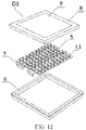
- the light source module L1 in an embodiment provided by the present invention is a light source product, which can be applied to a lighting device D1 as shown in FIG. 12 to provide classroom lighting.
- the lighting device D1 is a lamp panel, which may also be a chandelier, a ceiling lamp, etc. in other preferred embodiments, or the light source module L1 may also be applied to various lamps such as table lamp, down light, spotlight, etc.
- the lighting device D1 comprises a chassis 6, a face frame 8 provided with a diffusion plate 9, a light source module L1 arranged on the light source plate 5 and a power supply module 7 providing power required for the work of the light source module L1.
- the lighting device D1 may also be provided with a controller, a heat dissipation device, and a light distribution component, etc. according to the functions and requirements of specific lamps.
- the controller can be used to adjust the light color, light intensity, etc. of the irradiated light emitted by the light source module L1, and the light distribution component may also be a lampshade, a lens, a diffusion element, a light guide, etc. in addition to the diffusion plate in the embodiment.
- a specific embodiment of the light source module L1 of the present invention is a light-mixing white light LED packaging chip, which may be an LED chip with a general patch packaging structure or COB packaging structure. As shown in FIG. 1 , the light source module L1 comprises at least one first light-emitting element 1 and a packaging part 2 covering the first light-emitting element.
- the first light-emitting element 1 is a blue LED chip, which is directly excited by semiconductor materials, its peak wavelength of the light emission is located in the range of 435 ⁇ 465nm, and the light color is blue.
- LED chip comprises front-mounted chip or flip-chip, single LED chip or multiple LED chips are connected together in series, parallel or series parallel.
- the packaging part 2 uses transparent silica gel or transparent resin as a base material 204, and the transparent resin refers to one of epoxy resin and urea resin.
- the base material 204 is doped with a first additional luminous body 201, a second additional luminous body 202 and a third additional luminous body 203.
- the first additional luminous body 201 is blue-green fluorescent powder that receives part of the light emitted by the first light-emitting element 1 and converts it into the second color light with a peak wavelength of 485 ⁇ 515nm and a half width of 25 ⁇ 65nm.
- the second additional luminous body 202 comprises at least one of yellow fluorescent powder and green fluorescent powder with a peak wavelength of 520 ⁇ 580nm, a half width of the emission spectrum of 60 ⁇ 115nm, and an optional half width of 90 ⁇ 115nm. Because color is an intuitive perception of human body, it is impossible to accurately distinguish the spectral boundaries between yellow and green. In the present application, we call green fluorescent powder with a peak wavelength of 520 ⁇ 540nm and yellow fluorescent powder with a peak wavelength of 540 ⁇ 580nm. In the present application, the second additional luminous body 202 may adopt one of the yellow fluorescent powder and the green fluorescent powder, as in embodiment 1 hereafter. In other embodiments, two kinds of green powder may be mixed, as in embodiment 2 and embodiment 4.
- the second additional luminous body in embodiments 3, 5, 6, 7 and 8 adopts the scheme of yellow fluorescent powder and green fluorescent powder. That is, the second additional luminous body comprises a combination of the yellow fluorescent powder and the green fluorescent powder.
- the combined fluorescent powder receives part of the light emitted by the first light-emitting element 1 and converts it into the third color light with a peak wavelength of 520 ⁇ 580nm.
- the third additional luminous body 203 is the red fluorescent powder or orange fluorescent powder that receives part of the light emitted by the first light-emitting element 1 and converts it into the fourth color light with a peak wavelength of 615 ⁇ 655nm and a half width of 80 ⁇ 120nm, and the optional half width is 80 ⁇ 100nm.
- the packaging part 2 may also comprise a light diffuser, the light diffuser may be one of nano titanium oxide, nano alumina and nano silicon oxide.
- the above various fluorescent powder and light diffuser are weighed at the ratio and mixed into the base material 204, and then fully and evenly stirred in a mixer to make the fluorescent powder and light diffuser evenly distributed in the base material 204. After removing bubbles, the base material 204 mixed with fluorescent powder is covered over the blue LED chip as the first light-emitting element 1 by a dispensing machine to form the packaging part 2.
- the sum of the weight of the first additional luminous body, the second additional luminous body and the third additional luminous body is 20 ⁇ 45%.
- the weight of the packaging part 2 is the total weight of the base material 204 mixed with the fluorescent powder and light diffuser.
- the blue-green fluorescent powder as the first additional luminous body 201 accounts for 20.0 ⁇ 55.0% of the total fluorescent powder weight, which may be selected from any one of the following fluorescent powders or may be formed by mixing two or more of the following fluorescent powders.
- the combination of yellow fluorescent powder and green fluorescent powder as the second additional luminous body 202 accounts for 22.0 ⁇ 52.0% of the total fluorescent powder weight.
- the yellow fluorescent powder and the green fluorescent powder do not have a clear boundary, they basically have the same chemical general formula, and the difference is only that the molar ratios of components are different.
- embodiments 2-8 of the present application adopt two kinds of fluorescent powders with different peak wavelengths in the 520 ⁇ 580nm band for combination.
- the two kinds of fluorescent powders adopt different light colors, one of which is yellow fluorescent powder, we define that its peak wavelength is greater than 540nm, and the other is green fluorescent powder, and its peak wavelength is less than 540nm.
- two kinds of yellow fluorescent powder and green fluorescent powder with different peak wavelengths are selected for combination, mainly to improve visual performance and make the entire spectrum smoother.
- only one kind of yellow fluorescent powder or green fluorescent powder is selected to achieve the same CS value, but the visual performance may be slightly worse than that in this embodiment.
- the red fluorescent powder or the orange fluorescent powder as the third additional luminous body 203 accounts for 7.0 ⁇ 36.0% of the total fluorescent powder weight, which may be selected from any one of the following fluorescent powders, or may be formed by mixing two or more of the following fluorescent powders.
- the above shows the types of the fluorescent powders that may be selected.
- the parameters and chemical formulas of each fluorescent powder selected in the embodiments are shown in the table below. For ease of description, we have defined a code for the fluorescent powder in Table 1, we will describe the fluorescent powder with the code in the subsequent embodiment descriptions, and the peak value and chemical formula of the fluorescent powder will not be described in detail in each embodiment.
- the parameters in the above table are for the types of fluorescent powder, x and y represent the coordinate value of the light color of the fluorescent powder on the CIE1931 color space, Peak represents the peak wavelength, and Hw represents the half width.
- the above values are the actual values of the fluorescent powder used in the embodiments and are not a limitation of the present invention. Because in actual production, due to the difference in purity and particle size of the fluorescent powder, the peak wavelength and half width of the fluorescent powder may be deviated slightly from the above data, and this deviation value will generally be controlled within ⁇ 5nm. It should be considered that other schemes within this range are equivalent to the above fluorescent powder.
- Table 2 shows the eight embodiments of the present application, and the types of fluorescent powders and the weight of various types of fluorescent powders used in each embodiment.
- the ratio of each additional luminous body refers to the ratio of the weight of multiple fluorescent powders in each additional luminous body in the total fluorescent powder weight, respectively.
- the ratio of total fluorescent powder refers to the ratio of the total fluorescent powder weight, which refers to the weight of all fluorescent powders comprised in the three additional luminous body, in the total weight of the packaging part 2 after all the fluorescent powders are mixed with the base material 204.
- the base material 204 is transparent silica gel with a weight of 10g.
- the first additional luminous body The second additional luminous body
- the third additional luminous body The total fluorescent powder ratio Code Weight (g) Ratio Code Weight (g) Ratio Code Weight (g) Ratio Embo diment 1 BG500 1.63 33.3 % Y565 1.95 39.9 % R640 0.70 26.8% 32.8% R630 0.61 Embo diment 2 BG490 1.40 27.7 % G-Si525 0.90 43.5 % R630 1.46 28.9% 33.6% G-Ga53 5 1.30 Embo diment 3 BG490 1.35 26.2 % Y565 1.00 45.9 % R630 1.44 27.9% 34.0% G-Ga53 5 1.37 Embo diment 4 BG490 1.32 29.4 % G-L535 0.80 43.4 % R630 1.22 27.2% 31.0% G-Ga53 5 1.15 Embo diment 5 BG490 1.23 30.4 % Y550 0.80 43.3 % R630 1.06 26.2%
- the weight of the fluorescent powder in the embodiments in Table 2 is the data used for manufacturing the sample chip of the light source module L1. In fact, in mass production, the weight will vary slightly due to different batches of fluorescent powder, but its basic ratio is in a fixed range.
- the application of the amount of the various fluorescent powders is mainly to control the energy ratio of the mixed emitted light in the specified wavelength. Because the energy distribution affects the CS value of the emitted light (the specific calculation method of CS value will be described in detail later in the case of introducing the spectrum of the embodiments), we have a basic requirement for the energy distribution in each range when designing the chip.
- the entire spectral energy below refers to the total spectral energy in the visible light range, that is, in the wavelength range [380 ⁇ 780nm].
- the spectral energy in the wavelength range [380 ⁇ 470nm] accounts for 12.0% ⁇ 32.0% of the entire spectral energy, and optionally 17.0% ⁇ 27.0%
- the spectral energy in the wavelength range (470 ⁇ 560nm] accounts for 25.0% ⁇ 45.0% of the total spectral energy, and optionally 27.0% ⁇ 37.0%
- the spectral energy in the wavelength range (560 ⁇ 780nm] accounts for 36.0% ⁇ 56.0% of the total spectral energy, and optionally 40.0% ⁇ 50.0%.
- the (470 ⁇ 520nm] range is usually a wavelength valley with little energy, but in the present application, we pay special attention to this range and increase the CS value by increasing the energy in this range. Therefore, the spectral energy in this range is required to account for 14.0% ⁇ 34.0% of the total spectral energy, and optionally 18.0% ⁇ 28.0%.
- the fluorescent powder we use is also deployed based on this goal.
- the energy in the wavelength range [380 ⁇ 470nm] is provided by the blue LED chip of the first light-emitting element 1, and in fact, all the energy of the emitted light is provided by it. Originally, all the energy should be concentrated in this range, however, because part of the light is converted into other light colors by fluorescent powder, so the converted energy is distributed in other wavelength ranges, and the energy retained in this range is less than 32%.
- the spectral energy in the wavelength range (470 ⁇ 560nm] is mainly provided by the first additional luminous body 201 and the second additional luminous body 202 after converting part of the emitted light of the first light-emitting element 1.
- it is "mainly", because the spectrum is continuous, and the emitted light of the first light-emitting element 1 itself is not completely energy-free in this range, but is relatively small compared to the energy after conversion.
- the chip we mainly consider the conversion part of the fluorescent powder, select a more appropriate powder weight ratio, and then actually measure the energy in this range.
- the measured energy can comprise the energy provided by each luminous body, but it is the first additional luminous body 201 and the second additional luminous body 202 that play a main role in this range.
- the ratio of the blue-green fluorescent powder as the first additional luminous body 201 in the total fluorescent powder weight is in the range of 26.1% to 33.3%. Considering that other types of fluorescent powder can be used, it is considered that the ratio of the first additional luminous body 201 in the total fluorescent powder weight should be in the range of 20% ⁇ 55%.
- the purpose of adding the second additional luminous body 202 in the present application is to increase the energy of the (470 ⁇ 520nm] range, but the energy of this range should not be too high, otherwise the color of white light will be affected.
- the fluorescent powder as the second additional luminous body 202 is basically a combination of the yellow fluorescent powder and green fluorescent powder, and its ratio in the total fluorescent powder weight is in the range of 39.9% to 46.6%, In the present application, it is considered that the ratio of the second additional luminous body 202 in the total fluorescent powder weight should be in the range of 22.0 ⁇ 52.0%.
- the spectral energy in the wavelength range (560 ⁇ 780nm] is mainly provided by the red fluorescent powder or the orange fluorescent powder as the third additional luminous body 203.
- the ratio of the third additional luminous body 203 in the total fluorescent powder weight is in the range of 25.6% to 29.4%.
- the ratio of other fluorescent powder other than the embodiments can be expanded to the range of 7% ⁇ 36%.
- These fluorescent powders may be coated on the LED chip by being mixed into the transparent silica gel, or they may be remote fluorescent powders that may be arranged far away from the chip, or partially mixed into the packaging glue and partially set on the external surface.
- the present application is not limited thereto.
- each additional luminous body in the light source module 1 is to receive part of the light emitted by the first light-emitting element 1 and convert it into light with other colors different from the first color.
- the second additional luminous body 202 is the yellow fluorescent powder with the code Y565, and the weight of the yellow powder is 1.95g.
- the second additional luminous body 202 is composed of 0.90g of green fluorescent powder with the code G-Si525 and 1.30g of green fluorescent powder with the code G-Ga535.
- the second additional luminous body 202 is composed of yellow fluorescent powder with the code Y565 and green fluorescent powder with the code G-Ga535, where the yellow fluorescent powder is 1.00g and the green fluorescent powder is 1.37g.
- the second additional luminous body 202 is composed of 0.80g of green fluorescent powder with the code G-L535 and 1.15g of green fluorescent powder with the code G-Ga535.
- the second additional luminous body 202 is composed of yellow fluorescent powder with the code Y550 and green fluorescent powder with the code G-L535, where the yellow fluorescent powder is 0.80g and the green fluorescent powder G-L535 is 0.95g.
- the second additional luminous body 202 is composed of yellow fluorescent powder with the code Y565 and green fluorescent powder with the code G-Ga535, where the yellow fluorescent powder is 0.80g and the green fluorescent powder is 1.45g.
- the second additional luminous body 202 is composed of yellow fluorescent powder with the code Y565 and green fluorescent powder with the code G-Ga535, where the yellow fluorescent powder is 1.00g and the green fluorescent powder is 1.26g.
- the second additional luminous body 202 is composed of yellow fluorescent powder with the code Y565 and green fluorescent powder with the code G-Ga535, where the yellow fluorescent powder is 0.80g and the green fluorescent powder is 1.08g.
- Table 3 lists the luminous characteristics of the light source modules L1 in embodiments 1-8, where x, y represent the coordinate values of the light color of the emitted light of the light source module L1 on the x and y axes on the CIE1931 color coordinate system, CCT is the color temperature, duv represents the distance and direction of the color offset Planck trajectory in the color coordinate system, and CRI is the color rendering index.
- the CS value 500lux in the present application represents the CS value of the emitted light of the light source module L1 at the illuminance of 500lux.
- the light color of each embodiment falls near the black body trajectory with a correlated color temperature of 5750 ⁇ 400K, and the distance from the black body trajectory BBL is less than 0.006, that is, duv is in this range of -0.006 ⁇ 0.006, and all points fall in the quadrilateral region enclosed by four vertices D1 (0.3184,0.3401), D2 (0.3203,0.3189), D3 (0.3356,0.3323) and D4 (0.3364,0.3564), that is, the region 1 in the figure. After conducting user experiments on these embodiments in the later stage, it is found that the effects of the embodiments 1, 2, 4, 5, 6 and 7 are better, and from FIG.
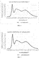
- FIG. 2 is a schematic spectrum diagram that best reflects the spectral characteristics of the emitted light of the light source module L1 of the present application. We will describe the spectral characteristics of the present application according to FIG. 2 .
- the spectrum of the emitted light comprises a first peak P1, a first peak valley V1, a second peak P2, a second peak valley V2 and a third peak P3 distributed in sequence.
- the first peak P1 is located in the wavelength region of 435 ⁇ 465nm. Since the light source module L1 uses the blue LED chip of the first light-emitting element 1 as the excitation light source, although a large part of the light emitted by the blue LED chip has been wavelength-converted by additional luminous bodies, there is still a part of the energy that has not been converted. These energies form the first peak in the wavelength region of 435 ⁇ 465nm.
- the P1 point may be the same as the peak wavelength of the blue LED chip, because the main source of the energy of this peak is the first light-emitting element 1, but the light converted by each additional luminous body may also have part of energy in this wavelength band.
- this first peak P1 does not necessarily coincide with the position of the peak wavelength of the blue LED chip of the original first light-emitting element 1, and may drift slightly, but it is still in the wavelength region of 435 ⁇ 465 nm.
- the first peak P1 is basically located in the range of [380 ⁇ 470nm], so the energy of the wavelength in the [380 ⁇ 470nm] range is mainly the energy of the first peak P1.
- the second peak P2 is located in the wavelength region of 485 ⁇ 525nm.
- the energy of the second peak P2 is provided by blue-green light, the blue-green fluorescent powder of the first light-emitting element 1 receives part of the light emitted by the blue LED chip of the first light-emitting element 1 and converts it into the blue-green light.
- the ratio of the spectral intensity of the second peak P2 to the spectral intensity of the first peak P1 is in the range of 45% ⁇ 85%, and optionally 55 ⁇ 75%.
- the third peak P3 is located in the wavelength region of 595 ⁇ 645nm.
- the energy of the third peak P3 is provided by red light
- the red fluorescent powder or orange fluorescent powder of the third additional luminous body 203 receives part of the light emitted by the blue LED chip of the first light-emitting element 1 converts it into the red light.
- the ratio of the spectral intensity of the third peak P3 to the spectral intensity of the first peak P1 is in the range of 40% ⁇ 70%, and optionally 42 ⁇ 60%.
- the spectral energy of emitted light in the wavelength range of (560 ⁇ 780nm] is mainly provided by the third peak P3.
- the first peak valley V1 is the lowest point in the spectrum between the first peak P1 and the second peak P2, and the energies at the bottom of the two peaks are superimposed here. Therefore, the ratio of the spectral intensity of the first peak valley V1 to the spectral intensity of the first peak P1 may be greater than or equal to 25.0%.
- the second peak valley V2 is the lowest point in the spectrum between the second peak P2 and the third peak P3. Since the second peak P2 and the third peak P3 are far apart, only relying on the energy of the second peak P2, it cannot be ensured that the spectral energy of the emitted light in the wavelength range (470 ⁇ 560nm) remains 25.0% ⁇ 45.0% of the entire spectral energy. Therefore, the second additional luminous body 202 is added in the present application, the second additional luminous body 202 receives part of the light emitted by the blue LED chip of the first light-emitting element 1 and converting it into the yellow and green light, and the energy provided by the yellow and green light is distributed in the region of (470 ⁇ 520nm].
- This energy distribution also raises the second peak valley V2, so that the ratio of the spectral intensity of the second peak valley V2 to the spectral intensity of the first peak P1 is in the range of 30.0% ⁇ 60.0%, and optionally 35.0% ⁇ 50.0%.
- selecting yellow or green fluorescent powder for the second additional luminous body can also ensure the energy ratio of this position, however, the spectrum fluctuates greatly, and another peak may be formed between the second peak P2 and the third peak P3.
- the appearance of the new peak does not affect the CS value of the entire spectrum, and the second peak valley V2 is still the lowest point in the spectrum located between the second peak P2 and the third peak P3.
- the energy distribution in this range is more uniform.
- the second additional luminous body 202 adopts a mixture of two kinds of fluorescent powders with different peak wavelengths, and optionally, the two kinds of fluorescent powder select fluorescent powders of different colors, that is, one is yellow fluorescent powder and the other is green fluorescent powder. After the two kinds of fluorescent powders are mixed, part of the emitted light of the first light-emitting element 1 is converted to provide the main energy in the wavelength range of (470 ⁇ 520nm]. The energy in the wavelength range of (470 ⁇ 570nm] is provided by the first additional luminous body 201 together with the second additional luminous body 202.
- the positions of the above peaks can basically ensure the energy ratio in each range, but further limiting the peak energy ratio between the second peak P2 and the third peak P3 can obtain better luminous effects, further ensure the acquisition of high CS values, and ensure high luminous efficiency and high color rendering.
- the ratio of the spectral intensity of the third peak P3 to the spectral intensity of the second peak P2 is in the range of 75% ⁇ 105%, and optionally 80% ⁇ 100%.
- Table 4 lists the characteristic values of each spectrum of embodiments 1-8.
- P1, P2, P3, V1 and V2 in the table refer to the wavelength of the first peak P1, the second peak P2, the third peak P3, the first peak valley V1 and the second peak valley V2, respectively, the unit is nm.
- I_P2/I_P1 refers to the ratio of the spectral intensity of the second peak P2 to the spectral intensity of the first peak P1
- I_P3/I_P1 refers to the ratio of the spectral intensity of the third peak P3 to the spectral intensity of the first peak P1
- I _V1/I_ P1 refers to the ratio of the spectral intensity of the first peak valley V1 to the spectral intensity of the first peak P1
- I_V2/I_P1 refers to the ratio of the spectral intensity of the second peak valley V2 to the spectral intensity of the first peak P1
- I_P3/I_P2 refers to the ratio of the spectral intensity of the third peak P3 to the spectral intensity of the second peak P2.
- Embodiment 1 450.0 500.0 615.0 465.0 570.0 61.2% 59.8% 52.2% 44.9% 97.7% Embodiment 2 450.0 500.0 615.0 475.0 560.0 59.3% 51.6% 28.2% 45.4% 86.9% Embodiment 3 450.0 500.0 620.0 475.0 575.0 62.5% 53.8% 32.9% 44.7% 86.1% Embodiment 450.0 500.0 620.0 475.0 570.0 57.4% 48.8% 31.5% 39.9% 85.1% 4 Embodiment 5 450.0 500.0 600.0 475.0 560.0 56.6% 46.3% 27.8% 42.3% 81.7% Embodiment 6 440.0 515.0 625.0 465.0 575.0 575.0
- the energy ratio of each range in Table 5 can ensure that the embodiments 1-8 achieve the luminous characteristics of high CS values.
Landscapes
- Engineering & Computer Science (AREA)
- General Engineering & Computer Science (AREA)
- Led Device Packages (AREA)
- Luminescent Compositions (AREA)
Abstract
Description
- The present invention claims the priority of the Chinese patent application filed with the
Chinese patent office on June 5, 2019 with the application number 201910486921.6 Chinese patent office on June 5, 2019 with the application number 201920842848.7 - The present invention relates to a light source module and a lighting device comprising the light source module.
- With the arrival and development of the third lighting technology revolution, incandescent lamps and halogen lamps, etc. have been gradually banned from production and sales all over the world due to low luminous efficiency and non-energy saving, and LED lighting appliances have been widely used instead. Existing LED lighting products mainly solve the problems of energy saving, illumination, color and color rendering. In the case of using the LED lighting products, more and more people are concerned that lighting may affect the physiological rhythm of human body. For the impact of lighting products on human physiological rhythm, we can evaluate it through the circadian stimulus evaluation model, that is, the CS value in the industry, the spectrum with high CS value is especially suitable for people to concentrate on study and work under the same illumination. At present, the lamps used in office buildings usually only consider the indicators such as color temperature and illumination, and there is no LED lighting product that can improve students' concentration by increasing the CS value, and can take into account energy saving, illumination, color and color rendering.
- The purpose of the present invention is to solve the above problems and find a cold white LED (5700K) light source with high CS values, high color rendering and high luminous efficiency.
- In order to realize the above functions, the technical scheme adopted by the present invention is to provide a light source module, which comprises a first light-emitting element and a packaging part covering the first light-emitting element. The first light-emitting element emits first color light with a peak wavelength of 435 ~ 465nm; the packaging part comprises: a first additional luminous body which is arranged to receive part of the light emitted by the first light-emitting element and convert it into second color light with a peak wavelength of 485 ~ 515nm; the second additional luminous body which is arranged to receive part of the light emitted by the first light-emitting element and convert it into third color light with a peak wavelength of 520 ~ 580nm; the third additional luminous body which is arranged to receive part of the light emitted by the first light-emitting element and convert it into fourth color light with a peak wavelength of 615 ~ 655nm, the first color light, the second color light, the third color light and the fourth color light are mixed to form emitted light of the light source module, and the emitted light is neutral white light, that is, on a CIE1931 color space, the emitted light is located in an interval enclosed by points with correlated color temperature of 5750±400K and distances from the black body trajectory duv=-0.006~0.006. The spectrum of the emitted light has following features: defining a spectrum of the emitted light is in a visible light range, that is, a wavelength range [380 ~ 780nm], as an entire spectral energy of the emitted light; a spectral energy in the wavelength range [380 ~ 470nm] accounts for 12.0% ~ 32.0% of the entire spectral energy; a spectral energy in the wavelength range (470 ~ 560nm] accounts for 25.0% ~ 45.0% of the entire spectral energy; a spectral energy in the wavelength range (560 ~ 780nm] accounts for 36.0% ~ 56.0% of the entire spectral energy; a spectral energy in the wavelength range (470 ~ 520nm] accounts for 14.0% ~ 34.0% of the entire spectral energy.
- Further, in the spectrum of the emitted light: the spectral energy in the wavelength range [380 ~ 470nm] accounts for 17.0% ~ 27.0% of the total spectral energy; the spectral energy in the wavelength range (470 ~ 560nm] accounts for 27.0% ~ 37.0% of the total spectral energy; the spectral energy in the wavelength range (560 ~ 780nm] accounts for 40.0% ~ 50.0% of the total spectral energy; and the spectral energy in the wavelength range (470 ~ 520nm] accounts for 18.0% ~ 28.0% of the total spectral energy.
- Further, the spectrum of the emitted light is continuously distributed in the visible light range of 380 ~ 780nm, and comprises three peaks and two peak valleys, a first peak is located in a wavelength range of 435 ~ 465 nm ; the second peak is located in a wavelength range of 485 ~ 525nm, and a ratio of a spectral intensity of the second peak to the spectral intensity of the first peak ranges from 45.0% to 85.0%; a first peak valley is located between the first peak and the second peak, and a ratio of a spectral intensity of the first peak valley to the spectral intensity of the first peak is greater than or equal to 25.0%; a third peak is located in a wavelength range of 595 ~ 645nm, and a ratio of a spectral intensity of the third peak to the spectral intensity of the first peak ranges from 40.0% to 70.0%; and a second peak valley is located between the second peak and the third peak, and a ratio of a spectral intensity of the second peak valley to the spectral intensity of the first peak ranges from 30.0% to 60.0%.
- Further, in the spectrum of the emitted light: the ratio of the spectral intensity of the second peak to the spectral intensity of the first peak ranges from 55.0% to 75.0%; the ratio of the spectral intensity of the third peak to the spectral intensity of the first peak ranges from 42.0% to 60.0%; and the ratio of the spectral intensity of the second peak valley to the spectral intensity of the first peak ranges from 35.0% to 50.0%.
- Further, in the spectrum of the emitted light: the ratio of the spectral intensity of the third peak to the spectral intensity of the second peak ranges from 75% to 105%.
- Further, in the spectrum of the emitted light: the ratio of the spectral intensity of the third peak to the spectral intensity of the second peak ranges from 80% to 100%.
- Further, the first light-emitting element is a blue LED emitting light with a peak wavelength of 435 ~ 465nm; the first additional luminous body is blue-green fluorescent powder with a peak wavelength of 485 ~ 515nm and a half width of 25 ~ 65nm; the second additional luminous body is yellow fluorescent powder and/or green fluorescent powder with a peak wavelength of 520 ~ 580nm and a half width of 60 ~ 115nm; the third additional luminous body is red fluorescent powder or orange fluorescent powder with a peak wavelength of 615 ~ 655nm and a half width of 80 ~ 120nm, and defining a total weight of the first additional luminous body, the second additional luminous body and the third additional luminous body to be a total fluorescent powder weight.
- Further, a ratio of the first additional luminous body in the total fluorescent powder weight ranges from 20.0 to 55.0%.
- Further, a ratio of the second additional luminous body in the total fluorescent powder weight ranges from 22.0% to 52.0%.
- Further, a ratio of the third additional luminous body in the total fluorescent powder weight ranges from 7.0% to 36.0%.
- Further, the blue-green fluorescent powder is formed by mixing any one or more of following fluorescent powder: (a) nitrogen oxide with Eu2+ as an activator, and general chemical composition formula: (Ba,Ca)1-xSi2N2O2:Eux, where x = 0.005 ~ 0.200; (b) Ga doped garnet fluorescent powder with Eu2+ as an activator, and general chemical composition formula: Ga-LuAG:Eu; (c) silicate fluorescent powder with Eu2+ as an activator, and general chemical composition formula: Ba2SiO4:Eu.
- Further, the yellow fluorescent powder/green fluorescent powder is formed by mixing any one or more of following fluorescent powder: (a) garnet structure fluorescent powder with Ce3+ as an activator, and general chemical composition formula: (M1)3-x(M2)5O12:Cex, where M1 is at least one element selected from a group consisting of Y, Lu, Gd and La, M2 is at least one element selected from a group consisting of of Al and Ga, and x = 0.005 ~ 0.200; (b) silicate system fluorescent powder with Eu2+ as an activator, and general chemical composition formula: (M3)2-xSiO4:Eux or (Ba,Ca,Sr)2-x(Mg,Zn)Si2O7:Eux, where M3 is at least one element selected from a group consisting of Mg, Sr, Ca and Ba, and x = 0.01 ~ 0.20; (c) nitrogen oxide fluorescent powder (Cylon β - SiALON) with Eu2+ as an activator, and general chemical composition formula: SibAlcOdNe:Eux, where x = 0.005 ~ 0.400, b + c = 12, and d + e = 16; (d) aluminate system fluorescent powder with Eu2+ as an activator, and general chemical composition formula: (Sr,Ba)2-xAl2O4:Eux or (Sr,Ba)4-xAl14O25:Eux, where x = 0.01 - 0.15.
- Further, the red fluorescent powder or the orange fluorescent powder is formed by mixing any one or more of following fluorescent powder: (a) nitride red powder having a 1113 crystal structure with Eu2+ as an activator, and general chemical composition formula: (M4)1-xAlSiN3:Euxr, where M4 is at least one element selected from a group consisting of Ca, Sr and Ba, x = 0.005 ~ 0.300; (b) nitride red powder having a 258 crystal structure with Eu2+ as an activator, and general chemical composition formula: (M5)2-xSi5N8:Eux, where M5 is at least one element selected from a group consisting of Ca, Sr, Ba and Mg, x = 0.005 ~ 0.300; (c) nitrogen oxide fluorescent powder (Cylon α - SiALON) with Eu2+ as an activator, and general chemical composition formula: ((M6)1-a)xSibAlcOdNe:Eua, where M6 is at least one element selected from a group consisting of Li, Na, K, Rb, Cs, Sr, Ba, Sc, Y, La and Gd, x = 0.15 ~ 1.5, a = 0.005 ~ 0.300, b + c = 12, and d + e = 16; (d) silicate fluorescent powder with Eu2+ as an activator, and general chemical composition formula: (Sr,Ba)3-xSi5O5:Eux.
- Further, the packaging part further comprises a base material and a light diffuser, the base material is silica gel or resin, and the light diffuser is one selected from a group consisting of nano titanium oxide, nano alumina and nano silicon oxide.
- Further, on the CIE1931 color space, light color of the emitted light of the light source module is located in a quadrilateral region enclosed by four vertices D1 (0.3184,0.3401), D2 (0.3203,0.3189), D3 (0.3356,0.3323) and D4 (0.3364,0.3564).
- Further, on the CIE1931 color space, the light color of the emitted light of the light source module is located within an elliptical range with a center point x0= 0.3281, y0= 0.3372, a long axis a = 0.00223, a short axis b = 0.00095, an inclination angle θ= 58.2 °, and an SDCM = 5.0.
- Further, in a case that the emitted light of the light source module has an illuminance of 500lux, a CS value is ≥ 0.45.
- Further, a color rendering index CRI of the emitted light of the light source module is ≥ 90.0.
- The present invention further provides a lighting device, which comprises the above light source module.
- The light source module provided by the present invention provides a cold white LED (5700K) light source with high luminous efficiency, high CS values and high color rendering by controlling the ratio of luminous energy of emitted light in different wavelength ranges. This kind of spectrum with high CS values is conducive to people's concentration for study and work under the same illumination and is especially suitable for office lighting.
-
-
FIG. 1 is a structural diagram of a light source module according to an embodiment of the present invention; -
FIG. 2 is a schematic diagram of spectral features of a light source module according to an embodiment of the present invention; -
FIG. 3 is a CIE1931 color coordinate diagram according toembodiment 1 toembodiment 8 of the present invention; -
FIG. 4 is a spectrum diagram of emitted light according toembodiment 1 of the present invention; -
FIG. 5 is a spectrum diagram of emitted light according to embodiment 2 of the present invention; -
FIG. 6 is a spectrum diagram of emitted light according to embodiment 3 of the present invention; -
FIG. 7 is a spectrum diagram of emitted light according to embodiment 4 of the present invention; -
FIG. 8 is a spectrum diagram of emitted light according toembodiment 5 of the present invention; -
FIG. 9 is a spectrum diagram of emitted light according toembodiment 6 of the present invention; -
FIG. 10 is a spectrum diagram of emitted light according to embodiment 7 of the present invention; -
FIG. 11 is a spectrum diagram of emitted light according toembodiment 8 of the present invention; and -
FIG. 12 is a structural diagram of a lamp according to an embodiment of the present invention. - A light source module and a lighting device proposed by the present invention are described in further detail below in combination with accompanying drawings and some embodiments in accordance with the present invention.
- As shown in
FIG. 1 , the light source module L1 in an embodiment provided by the present invention is a light source product, which can be applied to a lighting device D1 as shown inFIG. 12 to provide classroom lighting. The lighting device D1 is a lamp panel, which may also be a chandelier, a ceiling lamp, etc. in other preferred embodiments, or the light source module L1 may also be applied to various lamps such as table lamp, down light, spotlight, etc. The lighting device D1 comprises achassis 6, aface frame 8 provided with adiffusion plate 9, a light source module L1 arranged on thelight source plate 5 and a power supply module 7 providing power required for the work of the light source module L1. The lighting device D1 may also be provided with a controller, a heat dissipation device, and a light distribution component, etc. according to the functions and requirements of specific lamps. The controller can be used to adjust the light color, light intensity, etc. of the irradiated light emitted by the light source module L1, and the light distribution component may also be a lampshade, a lens, a diffusion element, a light guide, etc. in addition to the diffusion plate in the embodiment. - A specific embodiment of the light source module L1 of the present invention is a light-mixing white light LED packaging chip, which may be an LED chip with a general patch packaging structure or COB packaging structure. As shown in
FIG. 1 , the light source module L1 comprises at least one first light-emitting element 1 and a packaging part 2 covering the first light-emitting element. - The first light-
emitting element 1 is a blue LED chip, which is directly excited by semiconductor materials, its peak wavelength of the light emission is located in the range of 435 ~ 465nm, and the light color is blue. Here, we call the light emitted by the first light-emittingelement 1 as the first color light. LED chip comprises front-mounted chip or flip-chip, single LED chip or multiple LED chips are connected together in series, parallel or series parallel. - The packaging part 2 uses transparent silica gel or transparent resin as a
base material 204, and the transparent resin refers to one of epoxy resin and urea resin. Thebase material 204 is doped with a first additionalluminous body 201, a second additionalluminous body 202 and a third additionalluminous body 203. The first additionalluminous body 201 is blue-green fluorescent powder that receives part of the light emitted by the first light-emittingelement 1 and converts it into the second color light with a peak wavelength of 485 ~ 515nm and a half width of 25 ~ 65nm. The second additionalluminous body 202 comprises at least one of yellow fluorescent powder and green fluorescent powder with a peak wavelength of 520 ~ 580nm, a half width of the emission spectrum of 60 ~ 115nm, and an optional half width of 90 ~ 115nm. Because color is an intuitive perception of human body, it is impossible to accurately distinguish the spectral boundaries between yellow and green. In the present application, we call green fluorescent powder with a peak wavelength of 520 ~ 540nm and yellow fluorescent powder with a peak wavelength of 540 ~ 580nm. In the present application, the second additionalluminous body 202 may adopt one of the yellow fluorescent powder and the green fluorescent powder, as inembodiment 1 hereafter. In other embodiments, two kinds of green powder may be mixed, as in embodiment 2 and embodiment 4. However, in order to provide better color rendering, the second additional luminous body inembodiments element 1 and converts it into the third color light with a peak wavelength of 520 ~ 580nm. The third additionalluminous body 203 is the red fluorescent powder or orange fluorescent powder that receives part of the light emitted by the first light-emittingelement 1 and converts it into the fourth color light with a peak wavelength of 615 ~ 655nm and a half width of 80 ~ 120nm, and the optional half width is 80 ~ 100nm. The packaging part 2 may also comprise a light diffuser, the light diffuser may be one of nano titanium oxide, nano alumina and nano silicon oxide. The above various fluorescent powder and light diffuser are weighed at the ratio and mixed into thebase material 204, and then fully and evenly stirred in a mixer to make the fluorescent powder and light diffuser evenly distributed in thebase material 204. After removing bubbles, thebase material 204 mixed with fluorescent powder is covered over the blue LED chip as the first light-emittingelement 1 by a dispensing machine to form the packaging part 2. - Hereafter, we will illustrate the various fluorescent powders we use. For convenience of description, we define the sum of the weight of the first additional luminous body, the second additional luminous body and the third additional luminous body as the total fluorescent powder weight. The ratio of the total fluorescent powder weight in the packaging part 2 is 20 ~ 45%. The weight of the packaging part 2 is the total weight of the
base material 204 mixed with the fluorescent powder and light diffuser. - The blue-green fluorescent powder as the first additional
luminous body 201 accounts for 20.0 ~ 55.0% of the total fluorescent powder weight, which may be selected from any one of the following fluorescent powders or may be formed by mixing two or more of the following fluorescent powders. The specific types of fluorescent powders are as follows (in the present invention, the molar ratio is represented by x): (a) nitrogen oxide with Eu2+ as an activator and the general chemical composition formula: (Ba,Ca)1-xSi2N2O2:Eux, where x = 0.005 ~ 0.200; (b) Ga doped garnet fluorescent powder with Eu2+ as an activator and the general chemical composition formula: Ga-LuAG:Eu; and (c) silicate fluorescent powder with Eu2+ as an activator and the general chemical composition formula: Ba2SiO4:Eu. - In this embodiment, the combination of yellow fluorescent powder and green fluorescent powder as the second additional
luminous body 202 accounts for 22.0 ~ 52.0% of the total fluorescent powder weight. As mentioned above, there is no clear boundary between yellow and green. Similarly, the yellow fluorescent powder and the green fluorescent powder do not have a clear boundary, they basically have the same chemical general formula, and the difference is only that the molar ratios of components are different. Except forembodiment 1, embodiments 2-8 of the present application adopt two kinds of fluorescent powders with different peak wavelengths in the 520 ~ 580nm band for combination. Further, in theembodiments - The red fluorescent powder or the orange fluorescent powder as the third additional
luminous body 203 accounts for 7.0 ~ 36.0% of the total fluorescent powder weight, which may be selected from any one of the following fluorescent powders, or may be formed by mixing two or more of the following fluorescent powders. The specific kinds of fluorescent powders are as follows (in the present invention, the molar ratio is represented by x): (a) nitride red powder in a 1113 crystal structure with Eu2+ as an activator and the general chemical composition formula: (M1)1-xAlSiN3:Eux, where M1 is at least one element of Ca, Sr and Ba, x = 0.005 ~ 0.300; (b) nitride red powder in a 258 crystal structure with Eu2+ as an activator and the general chemical composition formula: (M2)2-xSi5N8:Eux, where M2 is at least one element of Ca, Sr, Ba and Mg, x = 0.005 ~ 0.300; (c) nitrogen oxide fluorescent powder (Cylon α- SiALON) with Eu2+ as an activator and the general chemical composition formula: ((M3)1-a)xSibAlcOdNe:Eua, where M3 is at least one element of Li, Na, K, Rb, Cs, Sr, Ba, Sc, Y, La and Gd, x = 0.15 ~ 1.5, a = 0.005 ~ 0.300, b + c = 12, d + e = 16; and (d) silicate fluorescent powder with Eu2+ as an activator and the general chemical composition formula: (Sr,Ba)3-xSi5O5:Eux, where x = 0.005 ~ 0.300. - The above shows the types of the fluorescent powders that may be selected. In the present application, we provide 8 specific embodiments. In these embodiments, a total of 9 kinds of fluorescent powders are selected. The parameters and chemical formulas of each fluorescent powder selected in the embodiments are shown in the table below. For ease of description, we have defined a code for the fluorescent powder in Table 1, we will describe the fluorescent powder with the code in the subsequent embodiment descriptions, and the peak value and chemical formula of the fluorescent powder will not be described in detail in each embodiment.
Table 1 No Color Code x y Peak (nm) Hw (nm) Chemical formula 1 red fluorescent powder R650 0.6692 0.3305 647.9 86.6 Ca1-xAlSiN3:Eux (x=0.01~0.10) 2 red fluorescent powder R640 0.6453 0.3540 639.2 95.1 3 red fluorescent powder R630 0.6377 0.3617 627.8 94.2 4 yellow fluorescent powder Y550 0.4165 0.5423 545.5 115.8 (Y,Gd)3-x(Ga,Al)5O12:Cex (x=0.008~0.10) 5 yellow fluorescent powder Y565 0.4546 0.5161 560.7 121.7 6 green fluorescent powder 1 G-Ga535 0.3564 0.5679 529.3 106.2 Y3-x(Ga,Al)5O12:Cex (x=0.01~0.10) 7 green fluorescent powder 2 G-L535 0.3780 0.5658 538.5 107.6 (Lu,Gd,La)3-xAl5O12:Cex (x=0.005~0.15) 8 blue- green fluorescent powder 1BG490 0.0761 0.4539 495.4 31.6 Ba1-xSi2N2O2:Eux (x=0.008~0.18) 9 blue-green fluorescent powder 2 BG500 0.0645 0.4675 500.0 38.1 (Lu,Gd,La)3-xAl5O12:Cex (x=0.005~0.15) - The parameters in the above table are for the types of fluorescent powder, x and y represent the coordinate value of the light color of the fluorescent powder on the CIE1931 color space, Peak represents the peak wavelength, and Hw represents the half width. The above values are the actual values of the fluorescent powder used in the embodiments and are not a limitation of the present invention. Because in actual production, due to the difference in purity and particle size of the fluorescent powder, the peak wavelength and half width of the fluorescent powder may be deviated slightly from the above data, and this deviation value will generally be controlled within ± 5nm. It should be considered that other schemes within this range are equivalent to the above fluorescent powder.
- Table 2 shows the eight embodiments of the present application, and the types of fluorescent powders and the weight of various types of fluorescent powders used in each embodiment. The ratio of each additional luminous body refers to the ratio of the weight of multiple fluorescent powders in each additional luminous body in the total fluorescent powder weight, respectively. The ratio of total fluorescent powder refers to the ratio of the total fluorescent powder weight, which refers to the weight of all fluorescent powders comprised in the three additional luminous body, in the total weight of the packaging part 2 after all the fluorescent powders are mixed with the
base material 204. In these embodiments, thebase material 204 is transparent silica gel with a weight of 10g.Table2 The first additional luminous body The second additional luminous body The third additional luminous body The total fluorescent powder ratio Code Weight (g) Ratio Code Weight (g) Ratio Code Weight (g) Ratio Embo diment 1 BG500 1.63 33.3 % Y565 1.95 39.9 % R640 0.70 26.8% 32.8% R630 0.61 Embo diment 2 BG490 1.40 27.7 % G-Si525 0.90 43.5 % R630 1.46 28.9% 33.6% G- Ga53 51.30 Embo diment 3 BG490 1.35 26.2 % Y565 1.00 45.9 % R630 1.44 27.9% 34.0% G- Ga53 51.37 Embo diment 4 BG490 1.32 29.4 % G-L535 0.80 43.4 % R630 1.22 27.2% 31.0% G- Ga53 51.15 Embo diment 5 BG490 1.23 30.4 % Y550 0.80 43.3 % R630 1.06 26.2% 28.8% G-L535 0.95 Embo diment 6 BG500 1.26 26.1 % Y565 0.80 46.6 % R630 1.32 27.3% 32.6% G-Ga535 1.45 Embo diment 7 BG490 1.47 27.8 % Y565 1.00 42.8 % R630 1.55 29.4% 34.6% G- Ga53 51.26 Embo diment 8 BG490 1.40 31.7 % Y565 0.80 42.6 % R630 1.13 25.6% 30.6% G- Ga53 51.08 - The weight of the fluorescent powder in the embodiments in Table 2 is the data used for manufacturing the sample chip of the light source module L1. In fact, in mass production, the weight will vary slightly due to different batches of fluorescent powder, but its basic ratio is in a fixed range. The application of the amount of the various fluorescent powders is mainly to control the energy ratio of the mixed emitted light in the specified wavelength. Because the energy distribution affects the CS value of the emitted light (the specific calculation method of CS value will be described in detail later in the case of introducing the spectrum of the embodiments), we have a basic requirement for the energy distribution in each range when designing the chip. Here, we only discuss the spectrum in the visible light range, so the entire spectral energy below refers to the total spectral energy in the visible light range, that is, in the wavelength range [380 ~ 780nm]. In the spectrum of emitted light of the chip: the spectral energy in the wavelength range [380 ~ 470nm] accounts for 12.0% ~ 32.0% of the entire spectral energy, and optionally 17.0% ~ 27.0%; the spectral energy in the wavelength range (470 ~ 560nm] accounts for 25.0% ~ 45.0% of the total spectral energy, and optionally 27.0% ~ 37.0%; the spectral energy in the wavelength range (560 ~ 780nm] accounts for 36.0% ~ 56.0% of the total spectral energy, and optionally 40.0% ~ 50.0%. In the previous RGB mixing schemes, the (470 ~ 520nm] range is usually a wavelength valley with little energy, but in the present application, we pay special attention to this range and increase the CS value by increasing the energy in this range. Therefore, the spectral energy in this range is required to account for 14.0% ~ 34.0% of the total spectral energy, and optionally 18.0% ~ 28.0%.
- In the case that the energy division in each spectral range is basically determined, the fluorescent powder we use is also deployed based on this goal. The energy in the wavelength range [380 ~ 470nm] is provided by the blue LED chip of the first light-emitting
element 1, and in fact, all the energy of the emitted light is provided by it. Originally, all the energy should be concentrated in this range, however, because part of the light is converted into other light colors by fluorescent powder, so the converted energy is distributed in other wavelength ranges, and the energy retained in this range is less than 32%. The spectral energy in the wavelength range (470 ~ 560nm] is mainly provided by the first additionalluminous body 201 and the second additionalluminous body 202 after converting part of the emitted light of the first light-emittingelement 1. Here, it is "mainly", because the spectrum is continuous, and the emitted light of the first light-emittingelement 1 itself is not completely energy-free in this range, but is relatively small compared to the energy after conversion. When designing the chip, we mainly consider the conversion part of the fluorescent powder, select a more appropriate powder weight ratio, and then actually measure the energy in this range. The measured energy can comprise the energy provided by each luminous body, but it is the first additionalluminous body 201 and the second additionalluminous body 202 that play a main role in this range. It can be seen from Table 2 that the ratio of the blue-green fluorescent powder as the first additionalluminous body 201 in the total fluorescent powder weight is in the range of 26.1% to 33.3%. Considering that other types of fluorescent powder can be used, it is considered that the ratio of the first additionalluminous body 201 in the total fluorescent powder weight should be in the range of 20% ~ 55%. The purpose of adding the second additionalluminous body 202 in the present application is to increase the energy of the (470 ~ 520nm] range, but the energy of this range should not be too high, otherwise the color of white light will be affected. It can be seen from Table 2 that the fluorescent powder as the second additionalluminous body 202 is basically a combination of the yellow fluorescent powder and green fluorescent powder, and its ratio in the total fluorescent powder weight is in the range of 39.9% to 46.6%, In the present application, it is considered that the ratio of the second additionalluminous body 202 in the total fluorescent powder weight should be in the range of 22.0 ~ 52.0%. The spectral energy in the wavelength range (560 ~ 780nm] is mainly provided by the red fluorescent powder or the orange fluorescent powder as the third additionalluminous body 203. In Table 2, the ratio of the third additionalluminous body 203 in the total fluorescent powder weight is in the range of 25.6% to 29.4%. It is further considered that the ratio of other fluorescent powder other than the embodiments can be expanded to the range of 7% ~ 36%. These fluorescent powders may be coated on the LED chip by being mixed into the transparent silica gel, or they may be remote fluorescent powders that may be arranged far away from the chip, or partially mixed into the packaging glue and partially set on the external surface. The present application is not limited thereto. - The function of each additional luminous body in the
light source module 1 is to receive part of the light emitted by the first light-emittingelement 1 and convert it into light with other colors different from the first color. In the present embodiment, the emitted light of the light source module L1 is formed after the first color light, the second color light, the third color light and the fourth color light are mixed, and on the CIE1931 color space, the emitted light of the light source module L1 is the white light in the interval enclosed by the points with a correlated color temperature 5750 ± 400K and distances from the black body trajectory duv = -0.006 - 0.006. - Refer to the table above for detailed description of each implementation.
- In the
embodiment 1, in the light source module L1, the first light-emittingelement 1 is a blue LED chip with Peak = 450 nm. Weigh and mix 0.70g of red fluorescent powder with the code of R640 and 0.61g of red fluorescent powder with the code R630 as the third additionalluminous body 203. The second additionalluminous body 202 is the yellow fluorescent powder with the code Y565, and the weight of the yellow powder is 1.95g. Weigh 1.63g of blue-green fluorescent powder with the code BG500 as the first additionalluminous body 201. Put the above fluorescent powder into 10.00g transparent silica gel, mix it fully and evenly in a mixer, coat it on the blue LED chip, dry and remove bubbles to obtain a cold white LED chip, its spectrum is shown inFIG. 4 , and the specific luminous characteristics are shown in Table 3. - In the embodiment 2, in the light source module L1, the first light-emitting
element 1 is a blue LED chip with Peak = 450 nm. Weigh 1.46g of red fluorescent powder with the code R630 as the third additionalluminous body 203. The second additionalluminous body 202 is composed of 0.90g of green fluorescent powder with the code G-Si525 and 1.30g of green fluorescent powder with the code G-Ga535. Weigh 1.40g of blue-green fluorescent powder with the code BG490 as the first additionalluminous body 201. Put the above fluorescent powder and 0.1g of light diffuser nano titanium oxide into 10.00g of transparent silica gel, mix it fully and evenly in a mixer, coat it on the blue LED chip, dry and remove bubbles to obtain a cold white LED chip, its spectrum is shown inFIG. 5 , and the specific luminous characteristics are shown in Table 3. - In the embodiment 3, in the light source module L1, the first light-emitting
element 1 is a blue LED chip with Peak = 450 nm. Weigh 1.44g of red fluorescent powder with the code R630 as the third additionalluminous body 203. The second additionalluminous body 202 is composed of yellow fluorescent powder with the code Y565 and green fluorescent powder with the code G-Ga535, where the yellow fluorescent powder is 1.00g and the green fluorescent powder is 1.37g. Weigh 1.35g of blue-green fluorescent powder with the code BG490 as the first additionalluminous body 201. Put the above fluorescent powder into 10.00g of transparent silica gel, mix it fully and evenly in a mixer, coat it on the blue LED chip, dry and remove bubbles to obtain a cold white LED chip, its spectrum is shown inFIG. 6 , and the specific luminous characteristics are shown in Table 3. - In the embodiment 4, in the light source module L1, the first light-emitting
element 1 is a blue LED chip with Peak = 450 nm. Weigh 1.22g of red fluorescent powder with the code R630 as the third additionalluminous body 203. The second additionalluminous body 202 is composed of 0.80g of green fluorescent powder with the code G-L535 and 1.15g of green fluorescent powder with the code G-Ga535. Weigh 1.32g of blue-green fluorescent powder with the code BG490 as the first additionalluminous body 201. Put the above fluorescent powder into transparent silica gel, mix it fully and evenly in a mixer, coat it on the blue LED chip, dry and remove bubbles to obtain a cold white LED chip, its spectrum is shown inFIG. 7 , and the specific luminous characteristics are shown in Table 3. - In the
embodiment 5, in the light source module L1, the first light-emittingelement 1 is a blue LED chip with Peak = 450 nm. Weigh 1.06g of red fluorescent powder with the code R630 as the third additionalluminous body 203. The second additionalluminous body 202 is composed of yellow fluorescent powder with the code Y550 and green fluorescent powder with the code G-L535, where the yellow fluorescent powder is 0.80g and the green fluorescent powder G-L535 is 0.95g. Weigh 1.23g of blue-green fluorescent powder with the code BG490 as the first additionalluminous body 201. Put the above fluorescent powder into transparent silica gel, mix it fully and evenly in a mixer, coat it on the blue LED chip, dry and remove bubbles to obtain a cold white LED chip, its spectrum is shown inFIG. 8 , and the specific luminous characteristics are shown in Table 3. - In the
embodiment 6, in the light source module L1, the first light-emittingelement 1 is a blue LED chip with Peak = 440 nm. Weigh 1.32g of red fluorescent powder with the code R630 as the third additionalluminous body 203. The second additionalluminous body 202 is composed of yellow fluorescent powder with the code Y565 and green fluorescent powder with the code G-Ga535, where the yellow fluorescent powder is 0.80g and the green fluorescent powder is 1.45g. Weigh 1.26g of blue-green fluorescent powder with the code BG500 as the first additionalluminous body 201. Put the above fluorescent powder into transparent silica gel, mix it fully and evenly in a mixer, coat it on the blue LED chip, dry and remove bubbles to obtain a cold white LED chip, its spectrum is shown inFIG. 9 , and the specific luminous characteristics are shown in Table 3. - In the embodiment 7, in the light source module L1, the first light-emitting
element 1 is a blue LED chip with Peak = 455 nm. Weigh 1.55g of red fluorescent powder with the code R630 as the third additionalluminous body 203. The second additionalluminous body 202 is composed of yellow fluorescent powder with the code Y565 and green fluorescent powder with the code G-Ga535, where the yellow fluorescent powder is 1.00g and the green fluorescent powder is 1.26g. Weigh 1.47g of blue-green fluorescent powder with the code BG490 as the first additionalluminous body 201. Put the above fluorescent powder into transparent silica gel, mix it fully and evenly in a mixer, coat it on the blue LED chip, dry and remove bubbles to obtain a positive white LED chip, its spectrum is shown inFIG. 10 , and the specific luminous characteristics are shown in Table 3. - In the
embodiment 8, in the light source module L1, the first light-emittingelement 1 is a blue LED chip with Peak = 450 nm. Weigh 1.13g of red fluorescent powder with the code R630 as the third additionalluminous body 203. The second additionalluminous body 202 is composed of yellow fluorescent powder with the code Y565 and green fluorescent powder with the code G-Ga535, where the yellow fluorescent powder is 0.80g and the green fluorescent powder is 1.08g. Weigh 1.40g of blue-green phosphor with the code BG490 as the first additionalluminous body 201. Put the above fluorescent powder into transparent silica gel, mix it fully and evenly in a mixer, coat it on the blue LED chip, dry and remove bubbles to obtain a day white LED chip, its spectrum is shown inFIG. 11 , and the specific luminous characteristics are shown in Table 3.Table3 x y CCT duv CRI CS_500lux Embodiment 1 0.3281 0.3373 5699 0.000 91.72 0.471 Embodiment 2 0.3304 0.3371 5591 -0.001 95.65 0.464 Embodiment 3 0.3305 0.3501 5585 0.005 96.02 0.451 Embodiment 4 0.3245 0.3384 5864 0.002 93.93 0.469 Embodiment 50.3217 0.3295 6027 -0.001 95.85 0.479 Embodiment 60.3290 0.3436 5652 0.003 93.11 0.453 Embodiment 7 0.3304 0.3317 5591 -0.004 91.03 0.476 Embodiment 80.3222 0.3233 6026 -0.005 95.51 0.484 - Table 3 lists the luminous characteristics of the light source modules L1 in embodiments 1-8, where x, y represent the coordinate values of the light color of the emitted light of the light source module L1 on the x and y axes on the CIE1931 color coordinate system, CCT is the color temperature, duv represents the distance and direction of the color offset Planck trajectory in the color coordinate system, and CRI is the color rendering index. The CS value 500lux in the present application represents the CS value of the emitted light of the light source module L1 at the illuminance of 500lux. The specific calculation formula is as follows:

where,




- From table 3, we can see that the CS values of the emitted light of the light source modules L1 of all the embodiments at the illuminance of 500lux are greater than 0.45, and the color rendering indexes conform to CRI ≥ 90.0. We mark the luminous light color in each embodiment on the CIE1931 color coordinate system. As shown in
FIG. 3 , the light color of each embodiment falls near the black body trajectory with a correlated color temperature of 5750 ± 400K, and the distance from the black body trajectory BBL is less than 0.006, that is, duv is in this range of -0.006 ~ 0.006, and all points fall in the quadrilateral region enclosed by four vertices D1 (0.3184,0.3401), D2 (0.3203,0.3189), D3 (0.3356,0.3323) and D4 (0.3364,0.3564), that is, theregion 1 in the figure. After conducting user experiments on these embodiments in the later stage, it is found that the effects of theembodiments FIG. 3 , it can be found that these points all fall into the region 2 shown in figure, and the region 2 is an ellipse with the central point x0 = 0.3281, y0 = 0.3372, the long axis a = 0.00223, the short axis b = 0.00095, the inclination angle θ= 58.2 °, and SDCM = 5.0. - The reason why the embodiments provided by us can achieve high CS value is mainly due to the energy distribution of the emitted light at different wavelengths. These characteristics are more specifically reflected in the waveform features of the spectrum in addition to the different energy distribution in the different wavelength regions defined earlier.
FIG. 2 is a schematic spectrum diagram that best reflects the spectral characteristics of the emitted light of the light source module L1 of the present application. We will describe the spectral characteristics of the present application according toFIG. 2 . As can be seen fromFIG. 2 , the spectrum of the emitted light comprises a first peak P1, a first peak valley V1, a second peak P2, a second peak valley V2 and a third peak P3 distributed in sequence. - The first peak P1 is located in the wavelength region of 435 ~ 465nm. Since the light source module L1 uses the blue LED chip of the first light-emitting
element 1 as the excitation light source, although a large part of the light emitted by the blue LED chip has been wavelength-converted by additional luminous bodies, there is still a part of the energy that has not been converted. These energies form the first peak in the wavelength region of 435 ~ 465nm. The P1 point may be the same as the peak wavelength of the blue LED chip, because the main source of the energy of this peak is the first light-emittingelement 1, but the light converted by each additional luminous body may also have part of energy in this wavelength band. After the two are mixed, this first peak P1 does not necessarily coincide with the position of the peak wavelength of the blue LED chip of the original first light-emittingelement 1, and may drift slightly, but it is still in the wavelength region of 435 ~ 465 nm. The first peak P1 is basically located in the range of [380 ~ 470nm], so the energy of the wavelength in the [380 ~ 470nm] range is mainly the energy of the first peak P1. - The second peak P2 is located in the wavelength region of 485 ~ 525nm. The energy of the second peak P2 is provided by blue-green light, the blue-green fluorescent powder of the first light-emitting
element 1 receives part of the light emitted by the blue LED chip of the first light-emittingelement 1 and converts it into the blue-green light. The ratio of the spectral intensity of the second peak P2 to the spectral intensity of the first peak P1 is in the range of 45% ~ 85%, and optionally 55 ~ 75%. - The third peak P3 is located in the wavelength region of 595 ~ 645nm. The energy of the third peak P3 is provided by red light, the red fluorescent powder or orange fluorescent powder of the third additional
luminous body 203 receives part of the light emitted by the blue LED chip of the first light-emittingelement 1 converts it into the red light. The ratio of the spectral intensity of the third peak P3 to the spectral intensity of the first peak P1 is in the range of 40% ~ 70%, and optionally 42 ~ 60%. The spectral energy of emitted light in the wavelength range of (560 ~ 780nm] is mainly provided by the third peak P3. - The first peak valley V1 is the lowest point in the spectrum between the first peak P1 and the second peak P2, and the energies at the bottom of the two peaks are superimposed here. Therefore, the ratio of the spectral intensity of the first peak valley V1 to the spectral intensity of the first peak P1 may be greater than or equal to 25.0%.
- The second peak valley V2 is the lowest point in the spectrum between the second peak P2 and the third peak P3. Since the second peak P2 and the third peak P3 are far apart, only relying on the energy of the second peak P2, it cannot be ensured that the spectral energy of the emitted light in the wavelength range (470 ~ 560nm) remains 25.0% ~ 45.0% of the entire spectral energy. Therefore, the second additional
luminous body 202 is added in the present application, the second additionalluminous body 202 receives part of the light emitted by the blue LED chip of the first light-emittingelement 1 and converting it into the yellow and green light, and the energy provided by the yellow and green light is distributed in the region of (470 ~ 520nm]. This energy distribution also raises the second peak valley V2, so that the ratio of the spectral intensity of the second peak valley V2 to the spectral intensity of the first peak P1 is in the range of 30.0% ~ 60.0%, and optionally 35.0% ~ 50.0%. Here we explain again that, generally, selecting yellow or green fluorescent powder for the second additional luminous body can also ensure the energy ratio of this position, however, the spectrum fluctuates greatly, and another peak may be formed between the second peak P2 and the third peak P3. Of course, the appearance of the new peak does not affect the CS value of the entire spectrum, and the second peak valley V2 is still the lowest point in the spectrum located between the second peak P2 and the third peak P3. However, from the perspective of color rendering, the energy distribution in this range is more uniform. Therefore, in theoptional embodiments luminous body 202 adopts a mixture of two kinds of fluorescent powders with different peak wavelengths, and optionally, the two kinds of fluorescent powder select fluorescent powders of different colors, that is, one is yellow fluorescent powder and the other is green fluorescent powder. After the two kinds of fluorescent powders are mixed, part of the emitted light of the first light-emittingelement 1 is converted to provide the main energy in the wavelength range of (470 ~ 520nm]. The energy in the wavelength range of (470 ~ 570nm] is provided by the first additionalluminous body 201 together with the second additionalluminous body 202. - The positions of the above peaks can basically ensure the energy ratio in each range, but further limiting the peak energy ratio between the second peak P2 and the third peak P3 can obtain better luminous effects, further ensure the acquisition of high CS values, and ensure high luminous efficiency and high color rendering. In a preferred embodiment, the ratio of the spectral intensity of the third peak P3 to the spectral intensity of the second peak P2 is in the range of 75% ~ 105%, and optionally 80% ~ 100%.
- In
FIG. 2 , we can see that the spectrum of the emitted light is continuously distributed. The so-called continuous distribution means that the spectral curve is relatively smooth and there is no large energy fluctuation between adjacent two points. As shown in the spectrum diagrams ofFIG. 4-FIG. 11 of each of the embodiments, there is no point with spectral energy of 0 between several peaks, such a spectral curve can ensure that there is a certain energy distribution at every point in the range of 380 ~ 780nm, so that the spectrum has better color rendering. - Table 4 lists the characteristic values of each spectrum of embodiments 1-8. P1, P2, P3, V1 and V2 in the table refer to the wavelength of the first peak P1, the second peak P2, the third peak P3, the first peak valley V1 and the second peak valley V2, respectively, the unit is nm. I_P2/I_P1 refers to the ratio of the spectral intensity of the second peak P2 to the spectral intensity of the first peak P1, I_P3/I_P1 refers to the ratio of the spectral intensity of the third peak P3 to the spectral intensity of the first peak P1, I _V1/I_ P1 refers to the ratio of the spectral intensity of the first peak valley V1 to the spectral intensity of the first peak P1, I_V2/I_P1 refers to the ratio of the spectral intensity of the second peak valley V2 to the spectral intensity of the first peak P1, I_P3/I_P2 refers to the ratio of the spectral intensity of the third peak P3 to the spectral intensity of the second peak P2.
Table4 P1 (nm) P2 (nm) P3 (nm) V1 (nm) V2 (nm) I_P2/ I_P1 I_P3/ I_P1 I_V1/ I_P1 I_V2/ I_P1 I_P3/ I_P2 Embodiment 1 450.0 500.0 615.0 465.0 570.0 61.2% 59.8% 52.2% 44.9% 97.7% Embodiment 2 450.0 500.0 615.0 475.0 560.0 59.3% 51.6% 28.2% 45.4% 86.9% Embodiment 3 450.0 500.0 620.0 475.0 575.0 62.5% 53.8% 32.9% 44.7% 86.1% Embodiment 450.0 500.0 620.0 475.0 570.0 57.4% 48.8% 31.5% 39.9% 85.1% 4 Embodiment 5450.0 500.0 600.0 475.0 560.0 56.6% 46.3% 27.8% 42.3% 81.7 % Embodiment 6 440.0 515.0 625.0 465.0 575.0 64.0% 57.7% 28.8% 45.8% 90.2% Embodiment 7 455.0 500.0 610.0 480.0 540.0 54.6% 49.0% 35.4% 41.9% 89.8 % Embodiment 8 450.0 500.0 605.0 475.0 630.0 52.7% 44.5% 25.9% 41.0% 84.4% - These characteristic values all fall in the range of the spectral features described above. Because of these characteristics, the embodiments 1-8 with these spectral features can achieve the energy ratio in the defined ranges. Table 5 lists the energy ratio in the specified range in each spectrum of embodiments 1-8. I_Σ [380-470] nm, I_Σ (470-520] nm, I_Σ [470-560] nm, I_Σ (560-780] nm, respectively represent the ratio of spectral energy of the listed wavelength range in the entire spectral energy.
Table5 I_Σ [380-470] nm I_Σ (470-520] nm I_Σ [470-560] nm I_Σ (560-780] nm Embodiment 1 18.9% 20.7% 35.8% 45.3% Embodiment 2 19.7% 19.3% 34.1% 46.2% Embodiment 3 17.7% 19.8% 35.3% 47.0% Embodiment 4 19.2% 19.8% 34.8% 46.0 % Embodiment 5 21.1% 19.8% 34.6% 44.3 % Embodiment 6 19.2% 19.2% 34.9% 45.9% Embodiment 7 19.7% 19.2% 33.2% 47.1 % Embodiment 8 21.8% 18.8% 33.2% 44.9% - The energy ratio of each range in Table 5 can ensure that the embodiments 1-8 achieve the luminous characteristics of high CS values.
- The above descriptions of the optional embodiments of the present invention is for illustration and description and is not intended to exhaust or limit the present invention to the specific forms disclosed. Obviously, many modifications and changes may be made, which may be obvious to those skilled in the art and should be comprised in the scope of the present invention defined by the appended claims.
Claims (19)
- A light source module, characterized in that, comprising a first light-emitting element and a packaging part covering the first light-emitting element,the first light-emitting element emits first color light with a peak wavelength of 435 ~ 465 nm;the packaging part comprises:a first additional luminous body which is arranged to receive part of light emitted by the first light-emitting element and convert it into second color light with a peak wavelength of 485 - 515 nm;a second additional luminous body which is arranged to receive part of light emitted by the first light-emitting element and convert it into third color light with a peak wavelength of 520 ~ 580nm;a third additional luminous body which is arranged to receive part of light emitted by the first light-emitting element and convert it into fourth color light with a peak wavelength of 615 ~ 655 nm,the first color light, the second color light, the third color light and the fourth color light are mixed to form emitted light of the light source module, the emitted light is neutral white light, that is, on a CIE1931 color space, the emitted light is located in an interval enclosed by points with correlated color temperature of 5750 ± 400K and distances from black body trajectory duv = -0.006 ~ 0.006,a spectrum of the emitted light has following features:defining a spectral energy of the spectrum of the emitted light in a visible light range, that is, a wavelength range [380 ~ 780nm], as an entire spectral energy of the emitted light;a spectral energy in a wavelength range [380 ~ 470nm] accounts for 12.0% ~ 32.0% of the entire spectral energy;a spectral energy in a wavelength range (470 ~ 560nm] accounts for 25.0% ~ 45.0% of the entire spectral energy;a spectral energy in a wavelength range (560 ~ 780nm] accounts for 36.0% ~ 56.0% of the entire spectral energy; anda spectral energy in a wavelength range (470 ~ 520nm] accounts for 14.0% ~ 34.0% of the entire spectral energy.
- The light source module according to claim 1, characterized in that, in the spectrum of the emitted light:the spectral energy in the wavelength range [380 ~ 470nm] accounts for 17.0% ~ 27.0% of the entire spectral energy;the spectral energy in the wavelength range (470 ~ 560nm] accounts for 27.0% ~ 37.0% of the entire spectral energy;the spectral energy in the wavelength range (560 ~ 780nm] accounts for 40.0% ~ 50.0% of the entire spectral energy; andthe spectral energy in the wavelength range (470 ~ 520nm] accounts for 18.0% ~ 28.0% of the entire spectral energy.
- The light source module according to claim 1, characterized in that, the spectrum of the emitted light is continuously distributed in the visible light range of 380 ~ 780nm, and comprises three peaks and two peak valleys, whereina first peak is located in a wavelength range of 435 ~ 465 nm;a second peak is located in a wavelength range of 485 ~ 525nm, and a ratio of a spectral intensity of the second peak to a spectral intensity of the first peak ranges from 45.0% to 85.0%;a first peak valley is located between the first peak and the second peak, and a ratio of a spectral intensity of the first peak valley to the spectral intensity of the first peak is greater than or equal to 25.0%;a third peak is located in a wavelength range of 595 ~ 645nm, and a ratio of a spectral intensity of the third peak to the spectral intensity of the first peak ranges from 40.0% to 70.0%; anda second peak valley is located between the second peak and the third peak, and a ratio of a spectral intensity of the second peak valley to the spectral intensity of the first peak ranges from 30.0% to 60.0%.
- The light source module according to claim 3, characterized in that, in the spectrum of the emitted light:the ratio of the spectral intensity of the second peak to the spectral intensity of the first peak ranges from 55.0% to 75.0%;the ratio of the spectral intensity of the third peak to the spectral intensity of the first peak ranges from 42.0% to 60.0%; andthe ratio of the spectral intensity of the second peak valley to the spectral intensity of the first peak ranges from 35.0% to 50.0%.
- The light source module according to claim 3, characterized in that, in the spectrum of the emitted light: the ratio of the spectral intensity of the third peak to the spectral intensity of the second peak ranges from 75% to 105%.
- The light source module according to claim 5, characterized in that, in the spectrum of the emitted light: the ratio of the spectral intensity of the third peak to the spectral intensity of the second peak ranges from 80% to 100%.
- The light source module according to claim 1, characterized in that, the first light-emitting element is a blue LED emitting light with a peak wavelength of 435 ~ 465nm; the first additional luminous body is blue-green fluorescent powder with a peak wavelength of 485 ~ 515nm and a half width of 25 ~ 65nm; the second additional luminous body is yellow fluorescent powder and/or green fluorescent powder with a peak wavelength of 520 ~ 580nm and a half width of 60 ~ 115nm; the third additional luminous body is red fluorescent powder or orange fluorescent powder with a peak wavelength of 615 ~ 655nm and a half width of 80 ~ 120nm, and defining a total weight of the first additional luminous body, the second additional luminous body and the third additional luminous body to be a total fluorescent powder weight.
- The light source module according to claim 7, characterized in that, a ratio of the first additional luminous body in the total fluorescent powder weight ranges from 20.0 to 55.0%.
- The light source module according to claim 7, characterized in that, a ratio of the second additional luminous body in the total fluorescent powder weight ranges from 22.0% to 52.0%.
- The light source module according to claim 7, characterized in that, a ratio of the third additional luminous body in the total fluorescent powder weight ranges from 7.0% to 36.0%.
- The light source module according to claim 7, characterized in that, the blue-green fluorescent powder is formed by mixing any one or more of following fluorescent powders:(a) nitrogen oxide with Eu2+ as an activator, andgeneral chemical composition formula: (Ba,Ca)1-xSi2N2O2:Eux,where x = 0.005 ~ 0.200;(b) Ga doped garnet fluorescent powder with Eu2+ as an activator, and
general chemical composition formula: Ga-LuAG:Eu;(c) silicate fluorescent powder with Eu2+ as an activator, and
general chemical composition formula: Ba2SiO4:Eu. - The light source module according to claim 7, characterized in that, the yellow fluorescent powder/green fluorescent powder is formed by mixing any one or more of following fluorescent powders:(a) garnet structure fluorescent powder with Ce3+ as an activator, andgeneral chemical composition formula: (M1)3-x(M2)5O12:Cex,where M1 is at least one element selected from a group consisting of Y, Lu, Gd and La, M2 is at least one element selected from a group consisting of Al and Ga, and x = 0.005 ~ 0.200;(b) silicate system fluorescent powder with Eu2+ as an activator, andgeneral chemical composition formula: (M3)2-xSiO4:Euxor (Ba,Ca,Sr)2-x(Mg,Zn)Si2O7:Eux,where M3 is at least one element selected from a group consisting of Mg, Sr, Ca and Ba, and x = 0.01 ~ 0.20;(c) nitrogen oxide fluorescent powder (Cylon β - SiALON) with Eu2+ as an activator, and general chemical composition formula: SibAlcOdNe:Eux,
where x = 0.005 ~ 0.400, b + c = 12, and d + e = 16;(d) aluminate system fluorescent powder with Eu2+ as an activator, andgeneral chemical composition formula: (Sr,Ba)2-xAl2O4:Euxor (Sr,Ba)4-xAl14O25:Eux,where x = 0.01 ~ 0.15. - The light source module according to claim 7, characterized in that, the red fluorescent powder or the orange fluorescent powder is formed by mixing any one or more of following fluorescent powders:(a) nitride red powder having a 1113 crystal structure with Eu2+ as an activator, and general chemical composition formula: (M4)1-xAlSiN3:Eux,
where M4 is at least one element selected from a group consisting of Ca, Sr and Ba, x = 0.005 - 0.300;(b) nitride red powder having a 258 crystal structure with Eu2+ as an activator, and general chemical composition formula: (M5)2-xSi5N8:Eux,
where M5 is at least one element selected from a group consisting of Ca, Sr, Ba and Mg, x = 0.005 - 0.300;(c) nitrogen oxide fluorescent powder (Cylon α - SiALON) with Eu2+ as an activator, and general chemical composition formula: ((M6)1-a)xSibAlcOdNe:Eua,
where M6 is at least one element selected from a group consisting of Li, Na, K, Rb, Cs, Sr, Ba, Sc, Y, La and Gd, x = 0.15 - 1.5, a = 0.005 - 0.300, b + c = 12, and d + e = 16;(d) silicate fluorescent powder with Eu2+ as an activator, and
general chemical composition formula: (Sr,Ba)3-xSi5O5:Eux. - The light source module according to claim 7, characterized in that, the packaging part further comprises a base material and a light diffuser, the base material is silica gel or resin, and the light diffuser is one selected from a group consisting of nano titanium oxide, nano alumina and nano silicon oxide.
- The light source module according to any one of claims 1-14, characterized in that, on the CIE1931 color space, light color of the emitted light of the light source module is located in a quadrilateral region enclosed by four vertices D1 (0.3184,0.3401), D2 (0.3203,0.3189), D3 (0.3356,0.3323) and D4 (0.3364,0.3564).
- The light source module according to claim 15, characterized in that, on the CIE1931 color space, the light color of the emitted light of the light source module is located within an elliptical range with a center point x0 = 0.3281, y0 = 0.3372, a long axis a = 0.00223, a short axis b = 0.00095, an inclination angle θ= 58.2 °, and a SDCM = 5.0.
- The light source module according to any one of claims 1-14 or 15, characterized in that, in a case that the emitted light of the light source module has an illuminance of 500lux, a CS value is ≥ 0.45.
- The light source module according to any one of claims 1-14 or 15, characterized in that, a color rendering index CRI of the emitted light of the light source module is ≥ 90.0.
- Alighting device, characterized in that, comprising: the light source module according to any one of claims 1 to 18.
Applications Claiming Priority (3)
| Application Number | Priority Date | Filing Date | Title |
|---|---|---|---|
| CN201910486921.6A CN110212076B (en) | 2019-06-05 | 2019-06-05 | A light source module and a lighting device including the light source module |
| CN201920842848.7U CN209963086U (en) | 2019-06-05 | 2019-06-05 | Light source module and lighting device comprising same |
| PCT/CN2020/093967 WO2020244512A1 (en) | 2019-06-05 | 2020-06-02 | Light source module and lighting device comprising same |
Publications (3)
| Publication Number | Publication Date |
|---|---|
| EP3982428A1 true EP3982428A1 (en) | 2022-04-13 |
| EP3982428A4 EP3982428A4 (en) | 2022-08-10 |
| EP3982428B1 EP3982428B1 (en) | 2023-12-27 |
Family
ID=73652754
Family Applications (1)
| Application Number | Title | Priority Date | Filing Date |
|---|---|---|---|
| EP20819278.1A Active EP3982428B1 (en) | 2019-06-05 | 2020-06-02 | White light source module and lighting device comprising the same |
Country Status (2)
| Country | Link |
|---|---|
| EP (1) | EP3982428B1 (en) |
| WO (1) | WO2020244512A1 (en) |
Cited By (1)
| Publication number | Priority date | Publication date | Assignee | Title |
|---|---|---|---|---|
| WO2024165315A1 (en) * | 2023-02-07 | 2024-08-15 | Zumtobel Lighting Gmbh | White-light led module and indirect lighting |
Families Citing this family (1)
| Publication number | Priority date | Publication date | Assignee | Title |
|---|---|---|---|---|
| CN117438418B (en) * | 2023-10-30 | 2024-11-05 | 东莞市立德达光电科技有限公司 | Integrated LED light source of trapping squid lamp |
Family Cites Families (10)
| Publication number | Priority date | Publication date | Assignee | Title |
|---|---|---|---|---|
| JP2015115506A (en) * | 2013-12-12 | 2015-06-22 | パナソニックIpマネジメント株式会社 | Illumination light source |
| CN105609494B (en) * | 2014-10-27 | 2019-03-01 | 光宝光电(常州)有限公司 | White light emitting device |
| US10153405B2 (en) * | 2016-02-26 | 2018-12-11 | Nichia Corporation | Fluorescent material, light emitting device, and method for producing fluorescent material |
| KR102373817B1 (en) * | 2017-05-02 | 2022-03-14 | 삼성전자주식회사 | White light emitting device and lighting apparatus |
| JP7092474B2 (en) * | 2017-08-21 | 2022-06-28 | シチズン電子株式会社 | Light emitting device |
| US20190103522A1 (en) * | 2017-09-26 | 2019-04-04 | Panasonic Intellectual Property Management Co., Ltd. | Lighting apparatus and light emitting apparatus |
| CN108598244B (en) * | 2018-06-25 | 2020-11-03 | 欧普照明股份有限公司 | A light source module and a lighting device including the light source module |
| CN108922955B (en) * | 2018-06-25 | 2024-04-16 | 欧普照明股份有限公司 | A light source module and a lighting device including the light source module |
| CN209963086U (en) * | 2019-06-05 | 2020-01-17 | 欧普照明股份有限公司 | Light source module and lighting device comprising same |
| CN110212076B (en) * | 2019-06-05 | 2024-03-19 | 欧普照明股份有限公司 | A light source module and a lighting device including the light source module |
-
2020
- 2020-06-02 WO PCT/CN2020/093967 patent/WO2020244512A1/en not_active Ceased
- 2020-06-02 EP EP20819278.1A patent/EP3982428B1/en active Active
Cited By (1)
| Publication number | Priority date | Publication date | Assignee | Title |
|---|---|---|---|---|
| WO2024165315A1 (en) * | 2023-02-07 | 2024-08-15 | Zumtobel Lighting Gmbh | White-light led module and indirect lighting |
Also Published As
| Publication number | Publication date |
|---|---|
| EP3982428A4 (en) | 2022-08-10 |
| WO2020244512A1 (en) | 2020-12-10 |
| EP3982428B1 (en) | 2023-12-27 |
Similar Documents
| Publication | Publication Date | Title |
|---|---|---|
| US11698182B2 (en) | Light source module and lighting device comprising same | |
| US10036516B2 (en) | LED lamp | |
| CN108922955B (en) | A light source module and a lighting device including the light source module | |
| CN108598244B (en) | A light source module and a lighting device including the light source module | |
| WO2020034390A1 (en) | Led white light device and preparation method therefor, and led backlight module | |
| CN110233197A (en) | A kind of light source module group and the lighting device including the light source module group | |
| CN114759131B (en) | Light emitting device and lighting apparatus | |
| CN107461717A (en) | A kind of light source module group and the lighting device including the light source module group | |
| CN114396572A (en) | Light source module, lighting system and lamp | |
| CN109148429A (en) | Light-emitting diode encapsulation structure | |
| EP3982428B1 (en) | White light source module and lighting device comprising the same | |
| WO2022143329A1 (en) | Light source module and illumination device comprising same | |
| CN209963086U (en) | Light source module and lighting device comprising same | |
| CN107546312A (en) | A kind of light source module group and the lighting device including the light source module group | |
| CN207247110U (en) | A kind of light source module group and the lighting device including the light source module group | |
| CN207247111U (en) | A kind of light source module group and the lighting device including the light source module group | |
| CN113757573B (en) | Light source module and lighting device | |
| CN209859973U (en) | Light source module and lighting device comprising same | |
| CN221237741U (en) | Light source, light source module and lighting device | |
| CN209515728U (en) | A light source module and a lighting device including the light source module | |
| CN221570309U (en) | Light source module, lighting system and lamp | |
| EP3965175B1 (en) | Light source module and lighting device comprising same | |
| CN112747263B (en) | A light source module and a lighting device including the light source module | |
| CN217847982U (en) | Light source module and lamp | |
| CN216079367U (en) | Light source module and lighting device |
Legal Events
| Date | Code | Title | Description |
|---|---|---|---|
| STAA | Information on the status of an ep patent application or granted ep patent |
Free format text: STATUS: THE INTERNATIONAL PUBLICATION HAS BEEN MADE |
|
| PUAI | Public reference made under article 153(3) epc to a published international application that has entered the european phase |
Free format text: ORIGINAL CODE: 0009012 |
|
| STAA | Information on the status of an ep patent application or granted ep patent |
Free format text: STATUS: REQUEST FOR EXAMINATION WAS MADE |
|
| 17P | Request for examination filed |
Effective date: 20211229 |
|
| AK | Designated contracting states |
Kind code of ref document: A1 Designated state(s): AL AT BE BG CH CY CZ DE DK EE ES FI FR GB GR HR HU IE IS IT LI LT LU LV MC MK MT NL NO PL PT RO RS SE SI SK SM TR |
|
| A4 | Supplementary search report drawn up and despatched |
Effective date: 20220711 |
|
| RIC1 | Information provided on ipc code assigned before grant |
Ipc: F21Y 103/10 20160101ALN20220705BHEP Ipc: F21Y 115/10 20160101ALN20220705BHEP Ipc: F21S 8/00 20060101ALI20220705BHEP Ipc: H01L 33/50 20100101AFI20220705BHEP |
|
| DAV | Request for validation of the european patent (deleted) | ||
| DAX | Request for extension of the european patent (deleted) | ||
| STAA | Information on the status of an ep patent application or granted ep patent |
Free format text: STATUS: EXAMINATION IS IN PROGRESS |
|
| 17Q | First examination report despatched |
Effective date: 20230316 |
|
| GRAP | Despatch of communication of intention to grant a patent |
Free format text: ORIGINAL CODE: EPIDOSNIGR1 |
|
| STAA | Information on the status of an ep patent application or granted ep patent |
Free format text: STATUS: GRANT OF PATENT IS INTENDED |
|
| RIC1 | Information provided on ipc code assigned before grant |
Ipc: F21Y 103/10 20160101ALN20230831BHEP Ipc: F21Y 115/10 20160101ALN20230831BHEP Ipc: F21S 8/00 20060101ALI20230831BHEP Ipc: H01L 33/50 20100101AFI20230831BHEP |
|
| INTG | Intention to grant announced |
Effective date: 20231004 |
|
| GRAS | Grant fee paid |
Free format text: ORIGINAL CODE: EPIDOSNIGR3 |
|
| GRAA | (expected) grant |
Free format text: ORIGINAL CODE: 0009210 |
|
| STAA | Information on the status of an ep patent application or granted ep patent |
Free format text: STATUS: THE PATENT HAS BEEN GRANTED |
|
| AK | Designated contracting states |
Kind code of ref document: B1 Designated state(s): AL AT BE BG CH CY CZ DE DK EE ES FI FR GB GR HR HU IE IS IT LI LT LU LV MC MK MT NL NO PL PT RO RS SE SI SK SM TR |
|
| REG | Reference to a national code |
Ref country code: GB Ref legal event code: FG4D |
|
| REG | Reference to a national code |
Ref country code: CH Ref legal event code: EP |
|
| REG | Reference to a national code |
Ref country code: DE Ref legal event code: R096 Ref document number: 602020023538 Country of ref document: DE |
|
| REG | Reference to a national code |
Ref country code: IE Ref legal event code: FG4D |
|
| REG | Reference to a national code |
Ref country code: NL Ref legal event code: FP |
|
| PG25 | Lapsed in a contracting state [announced via postgrant information from national office to epo] |
Ref country code: GR Free format text: LAPSE BECAUSE OF FAILURE TO SUBMIT A TRANSLATION OF THE DESCRIPTION OR TO PAY THE FEE WITHIN THE PRESCRIBED TIME-LIMIT Effective date: 20240328 |
|
| REG | Reference to a national code |
Ref country code: LT Ref legal event code: MG9D |
|
| PG25 | Lapsed in a contracting state [announced via postgrant information from national office to epo] |
Ref country code: LT Free format text: LAPSE BECAUSE OF FAILURE TO SUBMIT A TRANSLATION OF THE DESCRIPTION OR TO PAY THE FEE WITHIN THE PRESCRIBED TIME-LIMIT Effective date: 20231227 |
|
| PG25 | Lapsed in a contracting state [announced via postgrant information from national office to epo] |
Ref country code: ES Free format text: LAPSE BECAUSE OF FAILURE TO SUBMIT A TRANSLATION OF THE DESCRIPTION OR TO PAY THE FEE WITHIN THE PRESCRIBED TIME-LIMIT Effective date: 20231227 |
|
| PG25 | Lapsed in a contracting state [announced via postgrant information from national office to epo] |
Ref country code: LT Free format text: LAPSE BECAUSE OF FAILURE TO SUBMIT A TRANSLATION OF THE DESCRIPTION OR TO PAY THE FEE WITHIN THE PRESCRIBED TIME-LIMIT Effective date: 20231227 Ref country code: GR Free format text: LAPSE BECAUSE OF FAILURE TO SUBMIT A TRANSLATION OF THE DESCRIPTION OR TO PAY THE FEE WITHIN THE PRESCRIBED TIME-LIMIT Effective date: 20240328 Ref country code: FI Free format text: LAPSE BECAUSE OF FAILURE TO SUBMIT A TRANSLATION OF THE DESCRIPTION OR TO PAY THE FEE WITHIN THE PRESCRIBED TIME-LIMIT Effective date: 20231227 Ref country code: ES Free format text: LAPSE BECAUSE OF FAILURE TO SUBMIT A TRANSLATION OF THE DESCRIPTION OR TO PAY THE FEE WITHIN THE PRESCRIBED TIME-LIMIT Effective date: 20231227 Ref country code: BG Free format text: LAPSE BECAUSE OF FAILURE TO SUBMIT A TRANSLATION OF THE DESCRIPTION OR TO PAY THE FEE WITHIN THE PRESCRIBED TIME-LIMIT Effective date: 20240327 |
|
| REG | Reference to a national code |
Ref country code: AT Ref legal event code: MK05 Ref document number: 1645375 Country of ref document: AT Kind code of ref document: T Effective date: 20231227 |
|
| PG25 | Lapsed in a contracting state [announced via postgrant information from national office to epo] |
Ref country code: SE Free format text: LAPSE BECAUSE OF FAILURE TO SUBMIT A TRANSLATION OF THE DESCRIPTION OR TO PAY THE FEE WITHIN THE PRESCRIBED TIME-LIMIT Effective date: 20231227 Ref country code: RS Free format text: LAPSE BECAUSE OF FAILURE TO SUBMIT A TRANSLATION OF THE DESCRIPTION OR TO PAY THE FEE WITHIN THE PRESCRIBED TIME-LIMIT Effective date: 20231227 Ref country code: NO Free format text: LAPSE BECAUSE OF FAILURE TO SUBMIT A TRANSLATION OF THE DESCRIPTION OR TO PAY THE FEE WITHIN THE PRESCRIBED TIME-LIMIT Effective date: 20240327 Ref country code: LV Free format text: LAPSE BECAUSE OF FAILURE TO SUBMIT A TRANSLATION OF THE DESCRIPTION OR TO PAY THE FEE WITHIN THE PRESCRIBED TIME-LIMIT Effective date: 20231227 Ref country code: HR Free format text: LAPSE BECAUSE OF FAILURE TO SUBMIT A TRANSLATION OF THE DESCRIPTION OR TO PAY THE FEE WITHIN THE PRESCRIBED TIME-LIMIT Effective date: 20231227 |
|
| PG25 | Lapsed in a contracting state [announced via postgrant information from national office to epo] |
Ref country code: IS Free format text: LAPSE BECAUSE OF FAILURE TO SUBMIT A TRANSLATION OF THE DESCRIPTION OR TO PAY THE FEE WITHIN THE PRESCRIBED TIME-LIMIT Effective date: 20240427 |
|
| PG25 | Lapsed in a contracting state [announced via postgrant information from national office to epo] |
Ref country code: CZ Free format text: LAPSE BECAUSE OF FAILURE TO SUBMIT A TRANSLATION OF THE DESCRIPTION OR TO PAY THE FEE WITHIN THE PRESCRIBED TIME-LIMIT Effective date: 20231227 Ref country code: AT Free format text: LAPSE BECAUSE OF FAILURE TO SUBMIT A TRANSLATION OF THE DESCRIPTION OR TO PAY THE FEE WITHIN THE PRESCRIBED TIME-LIMIT Effective date: 20231227 |
|
| PG25 | Lapsed in a contracting state [announced via postgrant information from national office to epo] |
Ref country code: SK Free format text: LAPSE BECAUSE OF FAILURE TO SUBMIT A TRANSLATION OF THE DESCRIPTION OR TO PAY THE FEE WITHIN THE PRESCRIBED TIME-LIMIT Effective date: 20231227 |
|
| PG25 | Lapsed in a contracting state [announced via postgrant information from national office to epo] |
Ref country code: SM Free format text: LAPSE BECAUSE OF FAILURE TO SUBMIT A TRANSLATION OF THE DESCRIPTION OR TO PAY THE FEE WITHIN THE PRESCRIBED TIME-LIMIT Effective date: 20231227 Ref country code: SK Free format text: LAPSE BECAUSE OF FAILURE TO SUBMIT A TRANSLATION OF THE DESCRIPTION OR TO PAY THE FEE WITHIN THE PRESCRIBED TIME-LIMIT Effective date: 20231227 Ref country code: RO Free format text: LAPSE BECAUSE OF FAILURE TO SUBMIT A TRANSLATION OF THE DESCRIPTION OR TO PAY THE FEE WITHIN THE PRESCRIBED TIME-LIMIT Effective date: 20231227 Ref country code: IT Free format text: LAPSE BECAUSE OF FAILURE TO SUBMIT A TRANSLATION OF THE DESCRIPTION OR TO PAY THE FEE WITHIN THE PRESCRIBED TIME-LIMIT Effective date: 20231227 Ref country code: IS Free format text: LAPSE BECAUSE OF FAILURE TO SUBMIT A TRANSLATION OF THE DESCRIPTION OR TO PAY THE FEE WITHIN THE PRESCRIBED TIME-LIMIT Effective date: 20240427 Ref country code: EE Free format text: LAPSE BECAUSE OF FAILURE TO SUBMIT A TRANSLATION OF THE DESCRIPTION OR TO PAY THE FEE WITHIN THE PRESCRIBED TIME-LIMIT Effective date: 20231227 Ref country code: CZ Free format text: LAPSE BECAUSE OF FAILURE TO SUBMIT A TRANSLATION OF THE DESCRIPTION OR TO PAY THE FEE WITHIN THE PRESCRIBED TIME-LIMIT Effective date: 20231227 Ref country code: AT Free format text: LAPSE BECAUSE OF FAILURE TO SUBMIT A TRANSLATION OF THE DESCRIPTION OR TO PAY THE FEE WITHIN THE PRESCRIBED TIME-LIMIT Effective date: 20231227 |
|
| PGFP | Annual fee paid to national office [announced via postgrant information from national office to epo] |
Ref country code: FR Payment date: 20240624 Year of fee payment: 5 |
|
| PG25 | Lapsed in a contracting state [announced via postgrant information from national office to epo] |
Ref country code: PT Free format text: LAPSE BECAUSE OF FAILURE TO SUBMIT A TRANSLATION OF THE DESCRIPTION OR TO PAY THE FEE WITHIN THE PRESCRIBED TIME-LIMIT Effective date: 20240429 Ref country code: PL Free format text: LAPSE BECAUSE OF FAILURE TO SUBMIT A TRANSLATION OF THE DESCRIPTION OR TO PAY THE FEE WITHIN THE PRESCRIBED TIME-LIMIT Effective date: 20231227 |
|
| PG25 | Lapsed in a contracting state [announced via postgrant information from national office to epo] |
Ref country code: PT Free format text: LAPSE BECAUSE OF FAILURE TO SUBMIT A TRANSLATION OF THE DESCRIPTION OR TO PAY THE FEE WITHIN THE PRESCRIBED TIME-LIMIT Effective date: 20240429 Ref country code: PL Free format text: LAPSE BECAUSE OF FAILURE TO SUBMIT A TRANSLATION OF THE DESCRIPTION OR TO PAY THE FEE WITHIN THE PRESCRIBED TIME-LIMIT Effective date: 20231227 |
|
| PGFP | Annual fee paid to national office [announced via postgrant information from national office to epo] |
Ref country code: BE Payment date: 20240620 Year of fee payment: 5 |
|
| REG | Reference to a national code |
Ref country code: DE Ref legal event code: R097 Ref document number: 602020023538 Country of ref document: DE |
|
| PG25 | Lapsed in a contracting state [announced via postgrant information from national office to epo] |
Ref country code: DK Free format text: LAPSE BECAUSE OF FAILURE TO SUBMIT A TRANSLATION OF THE DESCRIPTION OR TO PAY THE FEE WITHIN THE PRESCRIBED TIME-LIMIT Effective date: 20231227 |
|
| PG25 | Lapsed in a contracting state [announced via postgrant information from national office to epo] |
Ref country code: DK Free format text: LAPSE BECAUSE OF FAILURE TO SUBMIT A TRANSLATION OF THE DESCRIPTION OR TO PAY THE FEE WITHIN THE PRESCRIBED TIME-LIMIT Effective date: 20231227 |
|
| PLBE | No opposition filed within time limit |
Free format text: ORIGINAL CODE: 0009261 |
|
| STAA | Information on the status of an ep patent application or granted ep patent |
Free format text: STATUS: NO OPPOSITION FILED WITHIN TIME LIMIT |
|
| REG | Reference to a national code |
Ref country code: DE Ref legal event code: R079 Ref document number: 602020023538 Country of ref document: DE Free format text: PREVIOUS MAIN CLASS: H01L0033500000 Ipc: H10H0020851000 |
|
| 26N | No opposition filed |
Effective date: 20240930 |
|
| PG25 | Lapsed in a contracting state [announced via postgrant information from national office to epo] |
Ref country code: MC Free format text: LAPSE BECAUSE OF FAILURE TO SUBMIT A TRANSLATION OF THE DESCRIPTION OR TO PAY THE FEE WITHIN THE PRESCRIBED TIME-LIMIT Effective date: 20231227 |
|
| REG | Reference to a national code |
Ref country code: CH Ref legal event code: PL |
|
| PG25 | Lapsed in a contracting state [announced via postgrant information from national office to epo] |
Ref country code: LU Free format text: LAPSE BECAUSE OF NON-PAYMENT OF DUE FEES Effective date: 20240602 |
|
| PG25 | Lapsed in a contracting state [announced via postgrant information from national office to epo] |
Ref country code: IE Free format text: LAPSE BECAUSE OF NON-PAYMENT OF DUE FEES Effective date: 20240602 |
|
| PG25 | Lapsed in a contracting state [announced via postgrant information from national office to epo] |
Ref country code: SI Free format text: LAPSE BECAUSE OF FAILURE TO SUBMIT A TRANSLATION OF THE DESCRIPTION OR TO PAY THE FEE WITHIN THE PRESCRIBED TIME-LIMIT Effective date: 20231227 Ref country code: CH Free format text: LAPSE BECAUSE OF NON-PAYMENT OF DUE FEES Effective date: 20240630 |
|
| PGFP | Annual fee paid to national office [announced via postgrant information from national office to epo] |
Ref country code: NL Payment date: 20250528 Year of fee payment: 6 |
|
| PGFP | Annual fee paid to national office [announced via postgrant information from national office to epo] |
Ref country code: DE Payment date: 20250617 Year of fee payment: 6 |
|
| PGFP | Annual fee paid to national office [announced via postgrant information from national office to epo] |
Ref country code: GB Payment date: 20250625 Year of fee payment: 6 |
|
| PG25 | Lapsed in a contracting state [announced via postgrant information from national office to epo] |
Ref country code: CY Free format text: LAPSE BECAUSE OF FAILURE TO SUBMIT A TRANSLATION OF THE DESCRIPTION OR TO PAY THE FEE WITHIN THE PRESCRIBED TIME-LIMIT; INVALID AB INITIO Effective date: 20200602 |
|
| REG | Reference to a national code |
Ref country code: BE Ref legal event code: MM Effective date: 20250630 |
|
| PG25 | Lapsed in a contracting state [announced via postgrant information from national office to epo] |
Ref country code: HU Free format text: LAPSE BECAUSE OF FAILURE TO SUBMIT A TRANSLATION OF THE DESCRIPTION OR TO PAY THE FEE WITHIN THE PRESCRIBED TIME-LIMIT; INVALID AB INITIO Effective date: 20200602 |
|
| PG25 | Lapsed in a contracting state [announced via postgrant information from national office to epo] |
Ref country code: BE Free format text: LAPSE BECAUSE OF NON-PAYMENT OF DUE FEES Effective date: 20250630 |
|
| PG25 | Lapsed in a contracting state [announced via postgrant information from national office to epo] |
Ref country code: FR Free format text: LAPSE BECAUSE OF NON-PAYMENT OF DUE FEES Effective date: 20250630 |