EP3982382A1 - Transformer with integral inductor - Google Patents
Transformer with integral inductor Download PDFInfo
- Publication number
- EP3982382A1 EP3982382A1 EP21190363.8A EP21190363A EP3982382A1 EP 3982382 A1 EP3982382 A1 EP 3982382A1 EP 21190363 A EP21190363 A EP 21190363A EP 3982382 A1 EP3982382 A1 EP 3982382A1
- Authority
- EP
- European Patent Office
- Prior art keywords
- transformer
- ferrite
- core
- primary winding
- secondary winding
- Prior art date
- Legal status (The legal status is an assumption and is not a legal conclusion. Google has not performed a legal analysis and makes no representation as to the accuracy of the status listed.)
- Granted
Links
Images



Classifications
-
- H—ELECTRICITY
- H01—ELECTRIC ELEMENTS
- H01F—MAGNETS; INDUCTANCES; TRANSFORMERS; SELECTION OF MATERIALS FOR THEIR MAGNETIC PROPERTIES
- H01F27/00—Details of transformers or inductances, in general
- H01F27/34—Special means for preventing or reducing unwanted electric or magnetic effects, e.g. no-load losses, reactive currents, harmonics, oscillations, leakage fields
- H01F27/38—Auxiliary core members; Auxiliary coils or windings
-
- H—ELECTRICITY
- H01—ELECTRIC ELEMENTS
- H01F—MAGNETS; INDUCTANCES; TRANSFORMERS; SELECTION OF MATERIALS FOR THEIR MAGNETIC PROPERTIES
- H01F27/00—Details of transformers or inductances, in general
- H01F27/24—Magnetic cores
- H01F27/255—Magnetic cores made from particles
-
- H—ELECTRICITY
- H01—ELECTRIC ELEMENTS
- H01F—MAGNETS; INDUCTANCES; TRANSFORMERS; SELECTION OF MATERIALS FOR THEIR MAGNETIC PROPERTIES
- H01F27/00—Details of transformers or inductances, in general
- H01F27/40—Structural association with built-in electric component, e.g. fuse
-
- H—ELECTRICITY
- H01—ELECTRIC ELEMENTS
- H01F—MAGNETS; INDUCTANCES; TRANSFORMERS; SELECTION OF MATERIALS FOR THEIR MAGNETIC PROPERTIES
- H01F3/00—Cores, Yokes, or armatures
- H01F3/10—Composite arrangements of magnetic circuits
- H01F3/12—Magnetic shunt paths
-
- H—ELECTRICITY
- H01—ELECTRIC ELEMENTS
- H01F—MAGNETS; INDUCTANCES; TRANSFORMERS; SELECTION OF MATERIALS FOR THEIR MAGNETIC PROPERTIES
- H01F3/00—Cores, Yokes, or armatures
- H01F3/10—Composite arrangements of magnetic circuits
- H01F3/14—Constrictions; Gaps, e.g. air-gaps
-
- H—ELECTRICITY
- H01—ELECTRIC ELEMENTS
- H01F—MAGNETS; INDUCTANCES; TRANSFORMERS; SELECTION OF MATERIALS FOR THEIR MAGNETIC PROPERTIES
- H01F38/00—Adaptations of transformers or inductances for specific applications or functions
- H01F38/08—High-leakage transformers or inductances
-
- H—ELECTRICITY
- H02—GENERATION; CONVERSION OR DISTRIBUTION OF ELECTRIC POWER
- H02M—APPARATUS FOR CONVERSION BETWEEN AC AND AC, BETWEEN AC AND DC, OR BETWEEN DC AND DC, AND FOR USE WITH MAINS OR SIMILAR POWER SUPPLY SYSTEMS; CONVERSION OF DC OR AC INPUT POWER INTO SURGE OUTPUT POWER; CONTROL OR REGULATION THEREOF
- H02M3/00—Conversion of DC power input into DC power output
- H02M3/22—Conversion of DC power input into DC power output with intermediate conversion into AC
- H02M3/24—Conversion of DC power input into DC power output with intermediate conversion into AC by static converters
- H02M3/28—Conversion of DC power input into DC power output with intermediate conversion into AC by static converters using discharge tubes with control electrode or semiconductor devices with control electrode to produce the intermediate AC
- H02M3/325—Conversion of DC power input into DC power output with intermediate conversion into AC by static converters using discharge tubes with control electrode or semiconductor devices with control electrode to produce the intermediate AC using devices of a triode or a transistor type requiring continuous application of a control signal
- H02M3/335—Conversion of DC power input into DC power output with intermediate conversion into AC by static converters using discharge tubes with control electrode or semiconductor devices with control electrode to produce the intermediate AC using devices of a triode or a transistor type requiring continuous application of a control signal using semiconductor devices only
- H02M3/33569—Conversion of DC power input into DC power output with intermediate conversion into AC by static converters using discharge tubes with control electrode or semiconductor devices with control electrode to produce the intermediate AC using devices of a triode or a transistor type requiring continuous application of a control signal using semiconductor devices only having several active switching elements
- H02M3/33576—Conversion of DC power input into DC power output with intermediate conversion into AC by static converters using discharge tubes with control electrode or semiconductor devices with control electrode to produce the intermediate AC using devices of a triode or a transistor type requiring continuous application of a control signal using semiconductor devices only having several active switching elements having at least one active switching element at the secondary side of an isolation transformer
- H02M3/33584—Bidirectional converters
-
- H—ELECTRICITY
- H01—ELECTRIC ELEMENTS
- H01F—MAGNETS; INDUCTANCES; TRANSFORMERS; SELECTION OF MATERIALS FOR THEIR MAGNETIC PROPERTIES
- H01F27/00—Details of transformers or inductances, in general
- H01F27/34—Special means for preventing or reducing unwanted electric or magnetic effects, e.g. no-load losses, reactive currents, harmonics, oscillations, leakage fields
- H01F2027/348—Preventing eddy currents
Definitions
- the invention relates generally to an electrical transformer. More specifically, the invention relates to an isolation transformer with an integral inductor that can be used in a direct current (DC) to DC converter.
- DC direct current
- Fig. 1 depicts a typical single-phase DAB converter, which comprises a primary converter coupled to a secondary converter via a single-phase magnetic circuit, which includes an isolation transformer.
- a single-phase DAB converter is often used, whereas a three-phase DAB converter ( Fig. 2 ) can be used for power demands larger than 5 kW.
- a primary winding of the isolation transformer includes a series inductor. The magnetic circuit for this type of transformer is shown in Fig. 3 .
- the series inductor occupies 40% to 45% of the overall volume of the magnetic circuit.
- the transformers can become bulkier, heavier, and costlier than desired to meet the design targets of an electronic assembly. Therefore, it would be advantageous to develop a transformer with an integral inductor to eliminate the series inductor, thereby improving its power density and reducing its size and cost.
- a transformer having a core comprised of a perimeter portion and central intervening portion.
- the perimeter portion is separated from the intervening portion by a first opening and a second opening.
- a primary winding and a secondary winding are wound around the intervening portion of the core.
- the primary winding is capable of electromagnetic interaction with the secondary winding.
- a pair of ferrite members arranged outwardly from a central axis of the central intervening portion of the core can increase a series inductance with the primary winding.
- each ferrite member may have an air gap next to the core to facilitate heat dissipation from the transformer or its integral inductor.
- the present invention further provides a transformer as claimed.
- the integral inductor eliminates the series inductor by raising leakage inductance and keeping the leakage inductance within a tight bound over the range of power output for the converter.
- the miniaturized magnetics enables easier integration with the converter due to more compact packaging and better thermal management.
- a transformer 26 with an integral inductor 152 is a transformer 26 with an integral inductor 152.
- the transformer 26 comprises a core 141, a primary winding 148, a secondary winding 149, and at least one ferrite member 150 disposed between the primary winding 148 and the secondary winding 149.
- the core 141 has a perimeter portion 142 and a central intervening portion 143. Air gaps 146 separate the central intervening portion 143 from the perimeter portion 142.
- the primary winding 148 and the secondary winding 149 which are wound around the central intervening portion 143 of the core 141, interior to the perimeter portion 142.
- the secondary winding 149 is wound about the perimeter portion 142 of the core 141.
- the primary winding 148 is capable of electromagnetic interaction with the secondary winding 149. Additionally, the primary winding 148 may be capable of coupling an alternating current frequency (e.g., radio frequencies) with the secondary winding 149. In some alternate embodiments of transformer 26, windings 148/149 are placed on the central intervening portion 143 and the perimeter portions 142, particularly for a transformer 26 for a three-phase DC-to-DC converter 111.
- the core 141 comprises one or more of the following: a ferrous material, a laminated iron core, a powdered iron core matrix in a resin, or a ferrite material.
- a pair of ferrite members 150 are arranged outward from a central axis of the central intervening portion 143 of the core 141 to increase a series inductance with the primary winding 148. As shown in Fig. 4A , a first ferrite member 150 is disposed on the front side of the intervening portion 143 and a second ferrite member 150 is disposed on the back of the intervening portion 143. Stated differently, the pair of ferrite members 150 are disposed on opposing sides of the core 141 relative to the central axis. In this configuration, the ferrite members 150 may concentrate or interact with the magnetic flux that emanates from the primary winding 148, the secondary winding 149, or both.
- the ferrite members 150 may attenuate or block DC energy paths, attenuate induced current (e.g., Eddy current) in the windings 148/149, or facilitate maintenance of a target inductance at a minimum threshold level, such as greater than or equal to 4 micro Henries ( ⁇ H).
- Each ferrite member 150 can have a substantially rectangular shape, a generally polyhedron shape, or a block shape. In the example embodiment shown in Fig. 4A , each ferrite member 150 has a width along the X-axis, a height along the Z-axis, and a depth along the Y-axis, forming a plate-shaped member 150.
- Fig. 4B shows the ferrite members 150 in isolation from the additional components of the transformer 26 to show their position relative to each other. As shown in Fig. 4B , the pair of ferrite members 150 are substantially parallel and open.
- each of the ferrite members 150 has an air gap about its perimeter that can pass ambient air or flowing air with respect to one or more openings 146 in the core 141 to support or enhance heat dissipation from the transformer 26 or its integral inductor 152.
- each ferrite member 150 can be centered with respect to the vertical dimension of the core 141 or with respect the openings 146 in the core 141 along the Z-axis.
- the height of the ferrite member 150 is generally less than or equal to the height of the core opening 146 to leave a perimeter air gap, such as a lower air gap 154 and an upper air gap 155, permitting dissipation of thermal energy from the transformer 26 or its integral inductor 152.
- air communication means that the air can flow between the air gap 154/155 that is exposed to the ambient air and one or more openings 146 in the core 141.
- Each ferrite member 150 can be centered with respect to the horizontal dimension of the core 141 or with respect to the outermost width of the openings 146 of the core 141 along the X-axis. As shown Fig. 4A , the width of the ferrite member 150 is generally less than or equal to the outermost portion of the core opening 146 width (in this example, the entire span of the two core openings 146 in Fig. 4A ) to leave a perimeter air gap, such as a left-side air gap 156 and a right-side air gap 157, for dissipation of thermal energy from the transformer 26 or its integral inductor 152.
- the air gaps 156/157 allow the ambient air to circulate within the openings 146 and around the primary winding 148, the secondary winding 149, or both to promote heat dissipation from the transformer 26 and the integral inductor 152.
- the ferrite members 150 may comprise closed form ferrite members 150 without material air gaps or ferrite members to surround, cage, or enmesh one or more windings 148/149 of the transformer 26.
- the ferrite member 150 may comprise a metal oxide, such as an oxide of iron, or other high-mu material to produce an isotropic (e.g., uniform properties along orthogonal axis or in different spatial dimensions) dielectric and magnetic material. Ferrite members 150 may be used to enclose the transformer 26, the primary winding 148, the secondary winding 149, or portions of transformer 26 and its windings. Alternatively, the ferrite members 150 may be composed of layers with different magnetic permeabilities. For example, the ferrite member may have a first layer composed of a lower permeability composition such as a nickel-zinc ferrite, whereas a second layer may be composed of a higher permeability composition such as a manganese-zinc ferrite composition. Further, each one of the ferrite members 150 may comprises a ferrite block or ferrite polyhedron
- the plurality of ferrite members 150 are U-shaped, C-shaped, box-portion-shaped, or substantially rectangular and can be connected to form a unified structure that is hollow to receive the central intervening portion 143, the primary winding 148, and the secondary winding 149.
- the pair of ferrite members 150 may have facing edges that are configured with snap-fit connectors to mechanically and magnetically connect the ferrite members 150.
- the ferrite members 150 may be interconnected by mechanical fasteners, adhesives, elastomers, or bonding agents.
- the transformer 26 disclosed herein can be used in power electronics, electronic assemblies, DC-to-DC converters 111, motor controls, power supplies, and other industrial applications.
- the series inductance of the integral inductor 152 of the transformer 26 supports power or energy transfer from the primary winding 148 to the secondary winding 149 of the transformer 26.
- the series inductance of an integral inductor 152 comprises a leakage inductance of equal to or greater than 4 ⁇ H.
- the ferrite members 150 ensure that leakage inductance does not decline below a threshold, such as 4 ⁇ H, resulting in a simplified control method. Otherwise, high bandwidth control may not be possible due to passage of DC current that could saturate the inductor. Further, the transformer 26 offers better protection of power devices on the primary side of DAB-based DC-to-DC converters 111 because the inductance will ensure that the bandwidth of control systems and the protection circuit is sufficient to respond to abnormal operating conditions.
- the transformer windings 148/149 can be configured to meet various design and technical requirements.
- the primary winding 148 may comprise a first winding and a second winding that are coupled in series to a first winding a node.
- the first winding node represents the interface between the primary winding 148 and the integral inductor 152.
- the primary winding 148 can be interleaved with the secondary winding 149.
- the primary terminals 162 are associated with the primary winding 148.
- the secondary terminals 163 are associated with the secondary winding 149.
- the ratio of turns between the primary winding 148 and the secondary winding 149, or vice versa is known and may be defined as N.
- the ratio of turns, N may depend upon whether the transformer 26 is a step-up configuration for input/output voltages or a step-down configuration for input/output voltages, for instance.
- the transformer 26 is adapted to be used with a DC-to-DC power converter 11/111 comprising a first power converter 12 coupled to the primary winding 148 and a second power converter 13 coupled to the secondary winding 149, wherein the series inductance supports power or energy transfer from the primary winding 148 to the secondary winding 149 of the transformer 26 (single-phase configuration) or transformers 26 (three-phase configuration).
- Fig. 5 shows a single-phase DAB-based DC-to-DC converter 11 with the transformer 26 disclosed herein.
- Figs. 6A and 6B show two different configurations of a three-phase DAB-based DC-to-DC converter 111. As shown in Fig. 6A , three single-phase transformers 26 are shown.
- Fig. 6B shows a unified core 141 with three intervening sections 143.
- the single-phase DAB-based DC-to-DC converter comprises a primary converter 12 coupled to a secondary converter 13 via the transformer 26.
- the primary converter 12 comprises first pair of primary switches and a second pair of primary switches.
- the primary switches are coupled between direct current terminals 22 of the primary converter 12.
- a primary capacitor 23 may be placed between the direct current terminals 22 to filter ripple current or unwanted alternating current components from the direct current bus.
- the primary direct current terminals 22 may be coupled to an energy source, such as a battery or another DC voltage source 25.
- the secondary converter 13 comprises secondary switches.
- the secondary switches are coupled between direct current terminals 24 of the secondary converter 13.
- a secondary capacitor 26 may be placed between the direct current terminals 24 to filter ripple current or unwanted alternating current components from the direct current bus.
- the secondary direct current terminals 24 may be coupled to an energy source, such as a battery or another DC voltage source 25.
- An inductor 152 is associated with at least one output terminal 36 of the primary switches. There are two output terminals 36 for a single phase full-bridge converter 11.
- the inductor 152 may be integral with a primary winding 148 of the transformer 26 or may comprise a separate, discrete inductor 152. Multiple inductors 152 may be used in some embodiments.
- the primary winding 148 of the transformer 26 is coupled to output terminals 36 of the primary switches via the inductor 152.
- a secondary winding 149 of the transformer 26 is coupled to output terminal 36 of the secondary switches.
- the DC-to-DC converters 111 shown in Figs. 6A-6B are similar to the single-phase converters 11, but use three-phases for the primary converter 12 and the secondary converter 13.
- a plurality of inductors 152 are associated with output terminals 36 of the primary switches.
- the inductors 152 may be integral with the primary winding 148 of each of the transformers 26 or may comprise separate, discrete inductors 152.
- Each transformer 26 is coupled between the primary converter 12 and the secondary converter 13.
- the primary winding 148 of the transformer 26 is coupled to output terminals 36 of the primary switches via the inductors 152.
- a secondary winding 149 of each transformer 26 is coupled to output terminals 36 of the secondary switches.
- the unified body transformer 26 depicted in Fig. 6B has a volume of 1.5 L, as opposed to a volume of 2.2 L for the three separate transformers 26 shown in Fig. 6A .
- the flux density in the ferrite members 150 remains below 0.4T.
- the retention elevation of leakage inductance by the ferrite members 150 ensure that the effective turn ratio of the transformer 26 remains close to the turn ratio of an ideal transformer.
- Magnetizing inductance remains > 10x of leakage inductance, ensuring that there is minimal distortion in current supplied by the primary converter 12 in single-phase and three-phase operation in DAB-based and resonant LLC mode.
- the ability to keep distortion to a minimal level will reduce on-loss in SiC power devices used in the primary converter 12. This characteristic can lead to improved converters 11/111 if the hardware is repurposed for an onboard battery charging application.
- the series inductor typically used with the primary winding 148 of the isolation transformer 26 adds to the size of the magnetic circuit. If the series inductor is simply removed, leakage inductance is not sufficient for proper control of DAB-based DC-to-DC converters 11/111.
- an isolation transformer 26 without a series inductor may have a size of 93 mm x 51 mm x 138 mm (i.e. 0.65 L), but would have a leakage inductance of about 0.98 ⁇ H.
- a transformer without a series inductor would have to grow in size to 138mm x 95 mm x 138 mm (i.e. 1.81 L), nearly triple the volume.
- Inserting the ferrite members 150 between the primary winding 148 and secondary winding 149 of the isolation transformer 26 permits a proper leakage inductance while minimizing the size of the magnetic circuit.
- the ferrite members 150 can take various shapes and sizes. For a closed form / circuit ferrite member 150 the flux density across the XY, XZ, and YZ planes is above 0.4 T, which could lead to core loss in the ferrite member 150 and excessive flux density based on saturation of the ferrite member 150. Excessive heat can cause the ferrite member 150 to experience deviation in its magnetic permeability. As a result, it is desirable to keep the leakage inductance of the ferrite member 150 below 0.4 T.
- the flux density in the XZ plain is absent as there is no magnetic material to divert or guide leakage flux between the primary winding 148 and secondary winding 149.
- This configuration eliminates saturation and overheating issues while maintaining a uniform field in the ferrite members 150 disposed in the XY plane.
- Figs. 7-8 shows a simplified electrical diagram of the transformer 26 with taps in the primary 148 and secondary windings 149. If the primary winding 148 and secondary winding 149 are tapped, series and parallel operation of SiC and GaN-based power converters 11/111 becomes feasible, as these types of converters 11/111 may require the windings of the transformer 26 to operate at voltage and power values that differ from designed values.
- the invention may also broadly consist in the parts, elements, steps, examples and/or features referred to or indicated in the specification individually or collectively in any and all combinations of two or more said parts, elements, steps, examples and/or features.
- one or more features in any of the embodiments described herein may be combined with one or more features from any other embodiment(s) described herein.
Landscapes
- Engineering & Computer Science (AREA)
- Power Engineering (AREA)
- Chemical & Material Sciences (AREA)
- Composite Materials (AREA)
- Dc-Dc Converters (AREA)
Abstract
Description
- This application claims the benefit under 35
U.S.C. § 119 of Provisional Application Serial No. 63/198,281, filed October 8, 2020 - This invention was made with U.S. government support under contract or award No. DE-EE0006521 awarded by the Department of Energy. The Government has certain rights in the invention. The award subrecipient, John Deere Electronic Solutions, Inc. of the aforementioned contract or award, elects title to any and all subject inventions set forth in this disclosure for U.S. and any European patent filings.
- The invention relates generally to an electrical transformer. More specifically, the invention relates to an isolation transformer with an integral inductor that can be used in a direct current (DC) to DC converter.
- Touch-safe DC export power (24V to 56V) from a high-voltage bus (≥600V) can be realized using a dual active bridge (DAB)-based DC-to-DC converter.
Fig. 1 depicts a typical single-phase DAB converter, which comprises a primary converter coupled to a secondary converter via a single-phase magnetic circuit, which includes an isolation transformer. For export power ≤5 kW, a single-phase DAB converter is often used, whereas a three-phase DAB converter (Fig. 2 ) can be used for power demands larger than 5 kW. For proper control of a DC-to-DC converter, a primary winding of the isolation transformer includes a series inductor. The magnetic circuit for this type of transformer is shown inFig. 3 . - The series inductor occupies 40% to 45% of the overall volume of the magnetic circuit. As the power density of DC-to-DC converters increases, the transformers can become bulkier, heavier, and costlier than desired to meet the design targets of an electronic assembly. Therefore, it would be advantageous to develop a transformer with an integral inductor to eliminate the series inductor, thereby improving its power density and reducing its size and cost.
- According to one embodiment of the present invention is a transformer having a core comprised of a perimeter portion and central intervening portion. The perimeter portion is separated from the intervening portion by a first opening and a second opening. A primary winding and a secondary winding are wound around the intervening portion of the core. The primary winding is capable of electromagnetic interaction with the secondary winding. A pair of ferrite members arranged outwardly from a central axis of the central intervening portion of the core can increase a series inductance with the primary winding. In accordance with another aspect of the disclosure, each ferrite member may have an air gap next to the core to facilitate heat dissipation from the transformer or its integral inductor. The present invention further provides a transformer as claimed.
- The integral inductor eliminates the series inductor by raising leakage inductance and keeping the leakage inductance within a tight bound over the range of power output for the converter. As a result, the miniaturized magnetics enables easier integration with the converter due to more compact packaging and better thermal management.
-
-
FIG. 1 is block diagram of a single-phase DC-to-DC converter as known in the prior art. -
FIG. 2 is a block diagram of a three-phase DC-to-DC converter as known in the prior art. -
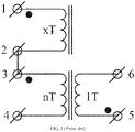
FIG. 3 is a schematic of the electrical circuit of a transformer with a series inductor as known in the prior art. -
FIG. 4A is a perspective view of one embodiment of the transformer with an open form ferrite block aligned in a region between the primary winding and secondary winding. -
FIG. 4B shows the ferrite members in isolation from the transformer for illustrative purposes. -
FIG. 5 shows one configuration of a transformed used with a single-phase DC-to-DC converter. -
FIGS. 6A-6B show alternative configurations of transformers used with a three-phase DC-to-DC converter. -
FIGS. 7-8 shows electrical diagrams for transformers used in single-phase (Fig. 7 ) and three-phase (Fig. 8 ) DAB-based DC-to-DC converters. - In one example embodiment, as shown in
Fig. 4A , is atransformer 26 with anintegral inductor 152. Thetransformer 26 comprises acore 141, aprimary winding 148, asecondary winding 149, and at least oneferrite member 150 disposed between theprimary winding 148 and thesecondary winding 149. Referring again toFig. 4A , thecore 141 has aperimeter portion 142 and a central interveningportion 143.Air gaps 146 separate the central interveningportion 143 from theperimeter portion 142. Further shown inFig. 4A is theprimary winding 148 and thesecondary winding 149, which are wound around the central interveningportion 143 of thecore 141, interior to theperimeter portion 142. Alternatively, thesecondary winding 149 is wound about theperimeter portion 142 of thecore 141. - The
primary winding 148 is capable of electromagnetic interaction with thesecondary winding 149. Additionally, theprimary winding 148 may be capable of coupling an alternating current frequency (e.g., radio frequencies) with thesecondary winding 149. In some alternate embodiments oftransformer 26,windings 148/149 are placed on the central interveningportion 143 and theperimeter portions 142, particularly for atransformer 26 for a three-phase DC-to-DC converter 111. Thecore 141 comprises one or more of the following: a ferrous material, a laminated iron core, a powdered iron core matrix in a resin, or a ferrite material. - A pair of
ferrite members 150 are arranged outward from a central axis of the central interveningportion 143 of thecore 141 to increase a series inductance with theprimary winding 148. As shown inFig. 4A , afirst ferrite member 150 is disposed on the front side of the interveningportion 143 and asecond ferrite member 150 is disposed on the back of the interveningportion 143. Stated differently, the pair offerrite members 150 are disposed on opposing sides of thecore 141 relative to the central axis. In this configuration, theferrite members 150 may concentrate or interact with the magnetic flux that emanates from theprimary winding 148, thesecondary winding 149, or both. Accordingly, theferrite members 150 may attenuate or block DC energy paths, attenuate induced current (e.g., Eddy current) in thewindings 148/149, or facilitate maintenance of a target inductance at a minimum threshold level, such as greater than or equal to 4 micro Henries (µH). Eachferrite member 150 can have a substantially rectangular shape, a generally polyhedron shape, or a block shape. In the example embodiment shown inFig. 4A , eachferrite member 150 has a width along the X-axis, a height along the Z-axis, and a depth along the Y-axis, forming a plate-shaped member 150.Fig. 4B shows theferrite members 150 in isolation from the additional components of thetransformer 26 to show their position relative to each other. As shown inFig. 4B , the pair offerrite members 150 are substantially parallel and open. - In one embodiment, each of the
ferrite members 150 has an air gap about its perimeter that can pass ambient air or flowing air with respect to one ormore openings 146 in thecore 141 to support or enhance heat dissipation from thetransformer 26 or itsintegral inductor 152. For example, eachferrite member 150 can be centered with respect to the vertical dimension of the core 141 or with respect theopenings 146 in thecore 141 along the Z-axis. InFig. 4A , the height of theferrite member 150 is generally less than or equal to the height of thecore opening 146 to leave a perimeter air gap, such as alower air gap 154 and anupper air gap 155, permitting dissipation of thermal energy from thetransformer 26 or itsintegral inductor 152. In some embodiments, air communication means that the air can flow between theair gap 154/155 that is exposed to the ambient air and one ormore openings 146 in thecore 141. - Each
ferrite member 150 can be centered with respect to the horizontal dimension of the core 141 or with respect to the outermost width of theopenings 146 of thecore 141 along the X-axis. As shownFig. 4A , the width of theferrite member 150 is generally less than or equal to the outermost portion of thecore opening 146 width (in this example, the entire span of the twocore openings 146 inFig. 4A ) to leave a perimeter air gap, such as a left-side air gap 156 and a right-side air gap 157, for dissipation of thermal energy from thetransformer 26 or itsintegral inductor 152. Theair gaps 156/157 allow the ambient air to circulate within theopenings 146 and around the primary winding 148, the secondary winding 149, or both to promote heat dissipation from thetransformer 26 and theintegral inductor 152. In alternative embodiments, theferrite members 150 may comprise closedform ferrite members 150 without material air gaps or ferrite members to surround, cage, or enmesh one ormore windings 148/149 of thetransformer 26. - The
ferrite member 150 may comprise a metal oxide, such as an oxide of iron, or other high-mu material to produce an isotropic (e.g., uniform properties along orthogonal axis or in different spatial dimensions) dielectric and magnetic material.Ferrite members 150 may be used to enclose thetransformer 26, the primary winding 148, the secondary winding 149, or portions oftransformer 26 and its windings. Alternatively, theferrite members 150 may be composed of layers with different magnetic permeabilities. For example, the ferrite member may have a first layer composed of a lower permeability composition such as a nickel-zinc ferrite, whereas a second layer may be composed of a higher permeability composition such as a manganese-zinc ferrite composition. Further, each one of theferrite members 150 may comprises a ferrite block or ferrite polyhedron - In an alternative configuration of the
transformer 26, the plurality offerrite members 150 are U-shaped, C-shaped, box-portion-shaped, or substantially rectangular and can be connected to form a unified structure that is hollow to receive thecentral intervening portion 143, the primary winding 148, and the secondary winding 149. For example, the pair offerrite members 150 may have facing edges that are configured with snap-fit connectors to mechanically and magnetically connect theferrite members 150. Alternatively, theferrite members 150 may be interconnected by mechanical fasteners, adhesives, elastomers, or bonding agents. - The
transformer 26 disclosed herein can be used in power electronics, electronic assemblies, DC-to-DC converters 111, motor controls, power supplies, and other industrial applications. The series inductance of theintegral inductor 152 of thetransformer 26 supports power or energy transfer from the primary winding 148 to the secondary winding 149 of thetransformer 26. In one example configuration of thetransformer 26, the series inductance of anintegral inductor 152 comprises a leakage inductance of equal to or greater than 4 µH. - The
ferrite members 150 ensure that leakage inductance does not decline below a threshold, such as 4 µH, resulting in a simplified control method. Otherwise, high bandwidth control may not be possible due to passage of DC current that could saturate the inductor. Further, thetransformer 26 offers better protection of power devices on the primary side of DAB-based DC-to-DC converters 111 because the inductance will ensure that the bandwidth of control systems and the protection circuit is sufficient to respond to abnormal operating conditions. - The
transformer windings 148/149 can be configured to meet various design and technical requirements. For DC-to-DC converters 111 that feature atransformer 26, the primary winding 148 may comprise a first winding and a second winding that are coupled in series to a first winding a node. The first winding node represents the interface between the primary winding 148 and theintegral inductor 152. In some configurations, the primary winding 148 can be interleaved with the secondary winding 149. Theprimary terminals 162 are associated with the primary winding 148. The secondary terminals 163 are associated with the secondary winding 149. The ratio of turns between the primary winding 148 and the secondary winding 149, or vice versa, is known and may be defined as N. The ratio of turns, N, may depend upon whether thetransformer 26 is a step-up configuration for input/output voltages or a step-down configuration for input/output voltages, for instance. - The
transformer 26 is adapted to be used with a DC-to-DC power converter 11/111 comprising afirst power converter 12 coupled to the primary winding 148 and asecond power converter 13 coupled to the secondary winding 149, wherein the series inductance supports power or energy transfer from the primary winding 148 to the secondary winding 149 of the transformer 26 (single-phase configuration) or transformers 26 (three-phase configuration). -
Fig. 5 shows a single-phase DAB-based DC-to-DC converter 11 with thetransformer 26 disclosed herein.Figs. 6A and 6B show two different configurations of a three-phase DAB-based DC-to-DC converter 111. As shown inFig. 6A , three single-phase transformers 26 are shown.Fig. 6B shows aunified core 141 with three interveningsections 143. - Referring again to
Fig. 5 , the single-phase DAB-based DC-to-DC converter comprises aprimary converter 12 coupled to asecondary converter 13 via thetransformer 26. Theprimary converter 12 comprises first pair of primary switches and a second pair of primary switches. The primary switches are coupled between directcurrent terminals 22 of theprimary converter 12. Aprimary capacitor 23 may be placed between the directcurrent terminals 22 to filter ripple current or unwanted alternating current components from the direct current bus. The primary directcurrent terminals 22 may be coupled to an energy source, such as a battery or anotherDC voltage source 25. Thesecondary converter 13 comprises secondary switches. The secondary switches are coupled between directcurrent terminals 24 of thesecondary converter 13. Asecondary capacitor 26 may be placed between the directcurrent terminals 24 to filter ripple current or unwanted alternating current components from the direct current bus. The secondary directcurrent terminals 24 may be coupled to an energy source, such as a battery or anotherDC voltage source 25. - An
inductor 152 is associated with at least oneoutput terminal 36 of the primary switches. There are twooutput terminals 36 for a single phase full-bridge converter 11. Theinductor 152 may be integral with a primary winding 148 of thetransformer 26 or may comprise a separate,discrete inductor 152.Multiple inductors 152 may be used in some embodiments. The primary winding 148 of thetransformer 26 is coupled tooutput terminals 36 of the primary switches via theinductor 152. A secondary winding 149 of thetransformer 26 is coupled tooutput terminal 36 of the secondary switches. - The DC-to-
DC converters 111 shown inFigs. 6A-6B are similar to the single-phase converters 11, but use three-phases for theprimary converter 12 and thesecondary converter 13. - A plurality of
inductors 152 are associated withoutput terminals 36 of the primary switches. Theinductors 152 may be integral with the primary winding 148 of each of thetransformers 26 or may comprise separate,discrete inductors 152. Eachtransformer 26 is coupled between theprimary converter 12 and thesecondary converter 13. The primary winding 148 of thetransformer 26 is coupled tooutput terminals 36 of the primary switches via theinductors 152. A secondary winding 149 of eachtransformer 26 is coupled tooutput terminals 36 of the secondary switches. - The
unified body transformer 26 depicted inFig. 6B has a volume of 1.5 L, as opposed to a volume of 2.2 L for the threeseparate transformers 26 shown inFig. 6A . For thetransformer 26 with a unified-body core 141, the flux density in theferrite members 150 remains below 0.4T. Further, the retention elevation of leakage inductance by theferrite members 150 ensure that the effective turn ratio of thetransformer 26 remains close to the turn ratio of an ideal transformer. Magnetizing inductance remains > 10x of leakage inductance, ensuring that there is minimal distortion in current supplied by theprimary converter 12 in single-phase and three-phase operation in DAB-based and resonant LLC mode. The ability to keep distortion to a minimal level will reduce on-loss in SiC power devices used in theprimary converter 12. This characteristic can lead toimproved converters 11/111 if the hardware is repurposed for an onboard battery charging application. - As previously discussed, the series inductor typically used with the primary winding 148 of the
isolation transformer 26 adds to the size of the magnetic circuit. If the series inductor is simply removed, leakage inductance is not sufficient for proper control of DAB-based DC-to-DC converters 11/111. For example, anisolation transformer 26 without a series inductor may have a size of 93 mm x 51 mm x 138 mm (i.e. 0.65 L), but would have a leakage inductance of about 0.98 µH. To raise the inductance, a transformer without a series inductor would have to grow in size to 138mm x 95 mm x 138 mm (i.e. 1.81 L), nearly triple the volume. Inserting theferrite members 150 between the primary winding 148 and secondary winding 149 of theisolation transformer 26 permits a proper leakage inductance while minimizing the size of the magnetic circuit. As discussed, theferrite members 150 can take various shapes and sizes. For a closed form /circuit ferrite member 150 the flux density across the XY, XZ, and YZ planes is above 0.4 T, which could lead to core loss in theferrite member 150 and excessive flux density based on saturation of theferrite member 150. Excessive heat can cause theferrite member 150 to experience deviation in its magnetic permeability. As a result, it is desirable to keep the leakage inductance of theferrite member 150 below 0.4 T. By using twoferrite members 150 disposed on opposing sides of the interveningcentral portion 143 of thecore 141, the flux density in the XZ plain is absent as there is no magnetic material to divert or guide leakage flux between the primary winding 148 and secondary winding 149. This configuration eliminates saturation and overheating issues while maintaining a uniform field in theferrite members 150 disposed in the XY plane. -
Figs. 7-8 shows a simplified electrical diagram of thetransformer 26 with taps in the primary 148 andsecondary windings 149. If the primary winding 148 and secondary winding 149 are tapped, series and parallel operation of SiC and GaN-basedpower converters 11/111 becomes feasible, as these types ofconverters 11/111 may require the windings of thetransformer 26 to operate at voltage and power values that differ from designed values. - When used in this specification and claims, the terms "comprises" and "comprising" and variations thereof mean that the specified features, steps or integers are included. The terms are not to be interpreted to exclude the presence of other features, steps or components.
- The invention may also broadly consist in the parts, elements, steps, examples and/or features referred to or indicated in the specification individually or collectively in any and all combinations of two or more said parts, elements, steps, examples and/or features. In particular, one or more features in any of the embodiments described herein may be combined with one or more features from any other embodiment(s) described herein.
- Protection may be sought for any features disclosed in any one or more published documents referenced herein in combination with the present disclosure.
- Although certain example embodiments of the invention have been described, the scope of the appended claims is not intended to be limited solely to these embodiments. The claims are to be construed literally, purposively, and/or to encompass equivalents.
Claims (11)
- A transformer comprising:a core comprising a perimeter portion joined to a central intervening portion,wherein the perimeter portion has an open interior,wherein the central intervening portion is disposed in the open interior of the perimeter portion creating a first opening and a second opening in the space between the central intervening portion and the perimeter portion;a primary winding wound around the central intervening portion;a secondary winding wound around the central intervening portion,
wherein the primary winding is capable of electromagnetic interaction with the secondary winding; andat least one ferrite member disposed between the primary winding and the secondary winding and arranged outward from a central axis of the central intervening portion of the core to increase a series inductance with the primary winding. - The transformer according to claim 1, wherein the at least one ferrite member has an air gap around its perimeter with respect to the core.
- The transformer according to claim 1 or 2, further comprising:a DC-to-DC power converter comprising a first power converter coupled to the primary winding and a second power converter coupled to the secondary winding,
wherein the series inductance supports power or energy transfer from the primary winding to the secondary winding of the transformer. - The transformer according to any preceding claim, wherein the series inductance comprises a leakage inductance of equal to or greater than 4 micro-Henries.
- The transformer according to any preceding claim, wherein the core comprises at least one material selected from the group consisting of: a ferrous material, a laminated iron core, a powdered iron core matrix in a resin, and a ferrite material.
- The transformer according to any preceding claim, wherein the at least one ferrite member comprises a ferrite block or ferrite polyhedron.
- The transformer according to any preceding claim, wherein the at least one ferrite member is a pair of ferrite members arranged outward from the primary winding and the secondary winding on opposing sides of the core.
- The transformer according to claim 7, wherein the pair of ferrite members are parallel.
- The transformer according to claim 7, wherein the pair of ferrite members comprise U-shaped members or substantially rectangular members joined to form a unified structure that is hollow to receive the central intervening portion, the primary winding, and the secondary winding.
- The transformer according to any preceding claim, wherein the primary winding is interleaved with the secondary winding.
- The transformer according to any preceding claim, wherein the secondary winding is wound around the perimeter portion of the core.
Applications Claiming Priority (1)
| Application Number | Priority Date | Filing Date | Title |
|---|---|---|---|
| US202063198281P | 2020-10-08 | 2020-10-08 |
Publications (2)
| Publication Number | Publication Date |
|---|---|
| EP3982382A1 true EP3982382A1 (en) | 2022-04-13 |
| EP3982382B1 EP3982382B1 (en) | 2025-08-27 |
Family
ID=77264998
Family Applications (1)
| Application Number | Title | Priority Date | Filing Date |
|---|---|---|---|
| EP21190363.8A Active EP3982382B1 (en) | 2020-10-08 | 2021-08-09 | Transformer with integral inductor |
Country Status (2)
| Country | Link |
|---|---|
| US (1) | US12131864B2 (en) |
| EP (1) | EP3982382B1 (en) |
Citations (4)
| Publication number | Priority date | Publication date | Assignee | Title |
|---|---|---|---|---|
| JPH10223458A (en) * | 1997-02-12 | 1998-08-21 | Bandou Denki Kk | Power transformer |
| US20060018134A1 (en) * | 2003-08-11 | 2006-01-26 | Mamoru Tsuruya | Switching power supply device |
| EP3425645A1 (en) * | 2017-07-03 | 2019-01-09 | Hamilton Sundstrand Corporation | Transformers with integrated inductors |
| US20190304676A1 (en) * | 2016-07-13 | 2019-10-03 | Mitsubishi Electric Corporation | Leakage transformer |
Family Cites Families (15)
| Publication number | Priority date | Publication date | Assignee | Title |
|---|---|---|---|---|
| CA1079823A (en) | 1976-12-14 | 1980-06-17 | General Electric Company | Sheet-wound transformer coils with reduced edge heating |
| US4520335A (en) | 1983-04-06 | 1985-05-28 | Westinghouse Electric Corp. | Transformer with ferromagnetic circuits of unequal saturation inductions |
| EP0292636A1 (en) | 1987-05-26 | 1988-11-30 | Landis & Gyr Betriebs AG | Current converter for measuring the current flowing in an electric conductor |
| FR2730874B1 (en) | 1995-02-16 | 1997-03-21 | Ugimag Sa | COMPOSITE INDUCTOR FOR ROTATING ELECTRIC MACHINES COMPRISING SINTERED PERMANENT MAGNETS COATED IN A FERROMAGNETIC BINDER |
| US5920473A (en) * | 1998-03-09 | 1999-07-06 | Magnetic Technology, Inc. | Dc-to-Dc power converter with integrated magnetic power transformer |
| JPWO2002021543A1 (en) | 2000-09-08 | 2004-01-15 | Necトーキン株式会社 | Permanent magnet, magnetic core using it as a magnet for magnetic bias, and inductance component using the same |
| KR100763083B1 (en) | 2006-01-09 | 2007-10-04 | 리엔 창 일렉트로닉 엔터프라이즈 컴퍼니 리미티드 | Power transformers with balanced windings and application circuits including them |
| US8466764B2 (en) | 2006-09-12 | 2013-06-18 | Cooper Technologies Company | Low profile layered coil and cores for magnetic components |
| JP5965617B2 (en) | 2011-11-16 | 2016-08-10 | Necトーキン株式会社 | Inductor |
| US20160133364A1 (en) * | 2014-11-07 | 2016-05-12 | Ford Global Technologies, Llc | Fixtures and Methods for Forming Aligned Magnetic Cores |
| CN110301019B (en) | 2017-05-05 | 2021-07-09 | 华为技术有限公司 | A transformer and switching power supply |
| JP6516942B1 (en) * | 2017-10-12 | 2019-05-22 | 三菱電機株式会社 | Power converter |
| EP3788644A4 (en) * | 2018-05-03 | 2023-03-01 | L. Pierre De Rochemont | HIGH-SPEED/LOW-POWER COMPUTER CENTERS AND SERVER NETWORKS |
| KR102174306B1 (en) | 2018-10-10 | 2020-11-04 | 이주열 | Planar transformer with insulation structure for improved performance |
| US10749441B1 (en) | 2019-10-11 | 2020-08-18 | Deere & Company | Method and system for controlling a direct current to direct current converter |
-
2021
- 2021-08-08 US US17/396,726 patent/US12131864B2/en active Active
- 2021-08-09 EP EP21190363.8A patent/EP3982382B1/en active Active
Patent Citations (4)
| Publication number | Priority date | Publication date | Assignee | Title |
|---|---|---|---|---|
| JPH10223458A (en) * | 1997-02-12 | 1998-08-21 | Bandou Denki Kk | Power transformer |
| US20060018134A1 (en) * | 2003-08-11 | 2006-01-26 | Mamoru Tsuruya | Switching power supply device |
| US20190304676A1 (en) * | 2016-07-13 | 2019-10-03 | Mitsubishi Electric Corporation | Leakage transformer |
| EP3425645A1 (en) * | 2017-07-03 | 2019-01-09 | Hamilton Sundstrand Corporation | Transformers with integrated inductors |
Non-Patent Citations (1)
| Title |
|---|
| LEE HAKSUN ET AL: "Design of Low-Profile Integrated Transformer and Inductor for Substrate-Embedding in 1-5kW Isolated GaN DC-DC Converters", 2017 IEEE 67TH ELECTRONIC COMPONENTS AND TECHNOLOGY CONFERENCE (ECTC), IEEE, 30 May 2017 (2017-05-30), pages 2256 - 2262, XP033136348, DOI: 10.1109/ECTC.2017.312 * |
Also Published As
| Publication number | Publication date |
|---|---|
| US20220115180A1 (en) | 2022-04-14 |
| US12131864B2 (en) | 2024-10-29 |
| EP3982382B1 (en) | 2025-08-27 |
Similar Documents
| Publication | Publication Date | Title |
|---|---|---|
| CN101661825B (en) | Magnetics for Power Converters | |
| US9613745B2 (en) | Adjustable integrated combined common mode and differential mode three phase inductors and methods of manufacture and use thereof | |
| US6980077B1 (en) | Composite magnetic core for switch-mode power converters | |
| US10170231B2 (en) | Choke and choke core | |
| JP7126210B2 (en) | reactor, power circuit | |
| EP2775488A1 (en) | Reactor, transformer, and power conversion apparatus using same | |
| EP2498266A2 (en) | Reactor and power converter using the same | |
| EP2624260A1 (en) | Forward converter with magnetic component | |
| AU2012209150B2 (en) | Harmonic mitigation devices and applications thereof | |
| EP1971016A2 (en) | Arrangement for the suppression of current harmonics | |
| US11244780B2 (en) | Storage choke | |
| JP2014535172A (en) | Induction parts and methods of use | |
| US12131864B2 (en) | Transformer with integral inductor | |
| US20210082609A1 (en) | Common-mode/differential-mode throttle for an electrically driveable motor vehicle | |
| AU2020422716B2 (en) | Magnetic components with electrically variable characteristics | |
| US20230326646A1 (en) | Common mode choke for connecting to dc side of power converter, filter arrangement, and power converter | |
| JP5004260B2 (en) | Outer iron type power transformer and power converter using the same | |
| WO2023282323A1 (en) | Magnetically coupled reactor and boosting circuit | |
| KR102878617B1 (en) | LLC resonant converter transformer | |
| US20250378984A1 (en) | Magnetic Integrated Inductor and Assembly Thereof | |
| EP4303897A1 (en) | Magnetic core | |
| US20250299874A1 (en) | High power high current transformer | |
| US20230039494A1 (en) | Electromagnetic device for converting energy | |
| EP3503133A1 (en) | Transformer arrangement |
Legal Events
| Date | Code | Title | Description |
|---|---|---|---|
| PUAI | Public reference made under article 153(3) epc to a published international application that has entered the european phase |
Free format text: ORIGINAL CODE: 0009012 |
|
| STAA | Information on the status of an ep patent application or granted ep patent |
Free format text: STATUS: THE APPLICATION HAS BEEN PUBLISHED |
|
| AK | Designated contracting states |
Kind code of ref document: A1 Designated state(s): AL AT BE BG CH CY CZ DE DK EE ES FI FR GB GR HR HU IE IS IT LI LT LU LV MC MK MT NL NO PL PT RO RS SE SI SK SM TR |
|
| STAA | Information on the status of an ep patent application or granted ep patent |
Free format text: STATUS: REQUEST FOR EXAMINATION WAS MADE |
|
| 17P | Request for examination filed |
Effective date: 20221012 |
|
| RBV | Designated contracting states (corrected) |
Designated state(s): AL AT BE BG CH CY CZ DE DK EE ES FI FR GB GR HR HU IE IS IT LI LT LU LV MC MK MT NL NO PL PT RO RS SE SI SK SM TR |
|
| STAA | Information on the status of an ep patent application or granted ep patent |
Free format text: STATUS: EXAMINATION IS IN PROGRESS |
|
| 17Q | First examination report despatched |
Effective date: 20240213 |
|
| RIC1 | Information provided on ipc code assigned before grant |
Ipc: H01F 27/34 20060101ALN20250508BHEP Ipc: H01F 3/12 20060101ALI20250508BHEP Ipc: H01F 38/08 20060101ALI20250508BHEP Ipc: H01F 27/40 20060101ALI20250508BHEP Ipc: H01F 27/38 20060101AFI20250508BHEP |
|
| GRAP | Despatch of communication of intention to grant a patent |
Free format text: ORIGINAL CODE: EPIDOSNIGR1 |
|
| STAA | Information on the status of an ep patent application or granted ep patent |
Free format text: STATUS: GRANT OF PATENT IS INTENDED |
|
| GRAS | Grant fee paid |
Free format text: ORIGINAL CODE: EPIDOSNIGR3 |
|
| RIC1 | Information provided on ipc code assigned before grant |
Ipc: H01F 27/34 20060101ALN20250604BHEP Ipc: H01F 3/12 20060101ALI20250604BHEP Ipc: H01F 38/08 20060101ALI20250604BHEP Ipc: H01F 27/40 20060101ALI20250604BHEP Ipc: H01F 27/38 20060101AFI20250604BHEP |
|
| INTG | Intention to grant announced |
Effective date: 20250613 |
|
| GRAA | (expected) grant |
Free format text: ORIGINAL CODE: 0009210 |
|
| STAA | Information on the status of an ep patent application or granted ep patent |
Free format text: STATUS: THE PATENT HAS BEEN GRANTED |
|
| P01 | Opt-out of the competence of the unified patent court (upc) registered |
Free format text: CASE NUMBER: APP_30455/2025 Effective date: 20250625 |
|
| AK | Designated contracting states |
Kind code of ref document: B1 Designated state(s): AL AT BE BG CH CY CZ DE DK EE ES FI FR GB GR HR HU IE IS IT LI LT LU LV MC MK MT NL NO PL PT RO RS SE SI SK SM TR |
|
| REG | Reference to a national code |
Ref country code: CH Ref legal event code: EP |
|
| REG | Reference to a national code |
Ref country code: DE Ref legal event code: R096 Ref document number: 602021037023 Country of ref document: DE |
|
| REG | Reference to a national code |
Ref country code: IE Ref legal event code: FG4D |
|
| REG | Reference to a national code |
Ref country code: CH Ref legal event code: W10 Free format text: ST27 STATUS EVENT CODE: U-0-0-W10-W00 (AS PROVIDED BY THE NATIONAL OFFICE) Effective date: 20251119 |
|
| RAP4 | Party data changed (patent owner data changed or rights of a patent transferred) |
Owner name: DEERE & COMPANY |
|
| REG | Reference to a national code |
Ref country code: NL Ref legal event code: MP Effective date: 20250827 |
|
| PG25 | Lapsed in a contracting state [announced via postgrant information from national office to epo] |
Ref country code: IS Free format text: LAPSE BECAUSE OF FAILURE TO SUBMIT A TRANSLATION OF THE DESCRIPTION OR TO PAY THE FEE WITHIN THE PRESCRIBED TIME-LIMIT Effective date: 20251227 |
|
| PG25 | Lapsed in a contracting state [announced via postgrant information from national office to epo] |
Ref country code: NO Free format text: LAPSE BECAUSE OF FAILURE TO SUBMIT A TRANSLATION OF THE DESCRIPTION OR TO PAY THE FEE WITHIN THE PRESCRIBED TIME-LIMIT Effective date: 20251127 |
|
| REG | Reference to a national code |
Ref country code: LT Ref legal event code: MG9D |
|
| PG25 | Lapsed in a contracting state [announced via postgrant information from national office to epo] |
Ref country code: PT Free format text: LAPSE BECAUSE OF FAILURE TO SUBMIT A TRANSLATION OF THE DESCRIPTION OR TO PAY THE FEE WITHIN THE PRESCRIBED TIME-LIMIT Effective date: 20251229 |
|
| PG25 | Lapsed in a contracting state [announced via postgrant information from national office to epo] |
Ref country code: FI Free format text: LAPSE BECAUSE OF FAILURE TO SUBMIT A TRANSLATION OF THE DESCRIPTION OR TO PAY THE FEE WITHIN THE PRESCRIBED TIME-LIMIT Effective date: 20250827 |
|
| PG25 | Lapsed in a contracting state [announced via postgrant information from national office to epo] |
Ref country code: NL Free format text: LAPSE BECAUSE OF FAILURE TO SUBMIT A TRANSLATION OF THE DESCRIPTION OR TO PAY THE FEE WITHIN THE PRESCRIBED TIME-LIMIT Effective date: 20250827 Ref country code: HR Free format text: LAPSE BECAUSE OF FAILURE TO SUBMIT A TRANSLATION OF THE DESCRIPTION OR TO PAY THE FEE WITHIN THE PRESCRIBED TIME-LIMIT Effective date: 20250827 |
|
| PG25 | Lapsed in a contracting state [announced via postgrant information from national office to epo] |
Ref country code: GR Free format text: LAPSE BECAUSE OF FAILURE TO SUBMIT A TRANSLATION OF THE DESCRIPTION OR TO PAY THE FEE WITHIN THE PRESCRIBED TIME-LIMIT Effective date: 20251128 |
|
| PG25 | Lapsed in a contracting state [announced via postgrant information from national office to epo] |
Ref country code: SE Free format text: LAPSE BECAUSE OF FAILURE TO SUBMIT A TRANSLATION OF THE DESCRIPTION OR TO PAY THE FEE WITHIN THE PRESCRIBED TIME-LIMIT Effective date: 20250827 |
|
| PG25 | Lapsed in a contracting state [announced via postgrant information from national office to epo] |
Ref country code: LV Free format text: LAPSE BECAUSE OF FAILURE TO SUBMIT A TRANSLATION OF THE DESCRIPTION OR TO PAY THE FEE WITHIN THE PRESCRIBED TIME-LIMIT Effective date: 20250827 |
|
| PG25 | Lapsed in a contracting state [announced via postgrant information from national office to epo] |
Ref country code: PL Free format text: LAPSE BECAUSE OF FAILURE TO SUBMIT A TRANSLATION OF THE DESCRIPTION OR TO PAY THE FEE WITHIN THE PRESCRIBED TIME-LIMIT Effective date: 20250827 Ref country code: BG Free format text: LAPSE BECAUSE OF FAILURE TO SUBMIT A TRANSLATION OF THE DESCRIPTION OR TO PAY THE FEE WITHIN THE PRESCRIBED TIME-LIMIT Effective date: 20250827 |
|
| PG25 | Lapsed in a contracting state [announced via postgrant information from national office to epo] |
Ref country code: RS Free format text: LAPSE BECAUSE OF FAILURE TO SUBMIT A TRANSLATION OF THE DESCRIPTION OR TO PAY THE FEE WITHIN THE PRESCRIBED TIME-LIMIT Effective date: 20251127 |
|
| PG25 | Lapsed in a contracting state [announced via postgrant information from national office to epo] |
Ref country code: ES Free format text: LAPSE BECAUSE OF FAILURE TO SUBMIT A TRANSLATION OF THE DESCRIPTION OR TO PAY THE FEE WITHIN THE PRESCRIBED TIME-LIMIT Effective date: 20250827 |
|
| REG | Reference to a national code |
Ref country code: AT Ref legal event code: MK05 Ref document number: 1830994 Country of ref document: AT Kind code of ref document: T Effective date: 20250827 |
|
| PG25 | Lapsed in a contracting state [announced via postgrant information from national office to epo] |
Ref country code: SM Free format text: LAPSE BECAUSE OF FAILURE TO SUBMIT A TRANSLATION OF THE DESCRIPTION OR TO PAY THE FEE WITHIN THE PRESCRIBED TIME-LIMIT Effective date: 20250827 |
|
| PG25 | Lapsed in a contracting state [announced via postgrant information from national office to epo] |
Ref country code: DK Free format text: LAPSE BECAUSE OF FAILURE TO SUBMIT A TRANSLATION OF THE DESCRIPTION OR TO PAY THE FEE WITHIN THE PRESCRIBED TIME-LIMIT Effective date: 20250827 |
|
| PG25 | Lapsed in a contracting state [announced via postgrant information from national office to epo] |
Ref country code: AT Free format text: LAPSE BECAUSE OF FAILURE TO SUBMIT A TRANSLATION OF THE DESCRIPTION OR TO PAY THE FEE WITHIN THE PRESCRIBED TIME-LIMIT Effective date: 20250827 |
|
| PG25 | Lapsed in a contracting state [announced via postgrant information from national office to epo] |
Ref country code: IT Free format text: LAPSE BECAUSE OF FAILURE TO SUBMIT A TRANSLATION OF THE DESCRIPTION OR TO PAY THE FEE WITHIN THE PRESCRIBED TIME-LIMIT Effective date: 20250827 |
|
| PG25 | Lapsed in a contracting state [announced via postgrant information from national office to epo] |
Ref country code: CZ Free format text: LAPSE BECAUSE OF FAILURE TO SUBMIT A TRANSLATION OF THE DESCRIPTION OR TO PAY THE FEE WITHIN THE PRESCRIBED TIME-LIMIT Effective date: 20250827 |
|
| PG25 | Lapsed in a contracting state [announced via postgrant information from national office to epo] |
Ref country code: SK Free format text: LAPSE BECAUSE OF FAILURE TO SUBMIT A TRANSLATION OF THE DESCRIPTION OR TO PAY THE FEE WITHIN THE PRESCRIBED TIME-LIMIT Effective date: 20250827 Ref country code: EE Free format text: LAPSE BECAUSE OF FAILURE TO SUBMIT A TRANSLATION OF THE DESCRIPTION OR TO PAY THE FEE WITHIN THE PRESCRIBED TIME-LIMIT Effective date: 20250827 |