EP3982325A1 - Processing system, processing method, and program - Google Patents
Processing system, processing method, and program Download PDFInfo
- Publication number
- EP3982325A1 EP3982325A1 EP20817727.9A EP20817727A EP3982325A1 EP 3982325 A1 EP3982325 A1 EP 3982325A1 EP 20817727 A EP20817727 A EP 20817727A EP 3982325 A1 EP3982325 A1 EP 3982325A1
- Authority
- EP
- European Patent Office
- Prior art keywords
- light
- feature amount
- imaging apparatus
- imaging
- extracted
- Prior art date
- Legal status (The legal status is an assumption and is not a legal conclusion. Google has not performed a legal analysis and makes no representation as to the accuracy of the status listed.)
- Pending
Links
Images




Classifications
-
- G—PHYSICS
- G06—COMPUTING OR CALCULATING; COUNTING
- G06V—IMAGE OR VIDEO RECOGNITION OR UNDERSTANDING
- G06V40/00—Recognition of biometric, human-related or animal-related patterns in image or video data
- G06V40/10—Human or animal bodies, e.g. vehicle occupants or pedestrians; Body parts, e.g. hands
- G06V40/18—Eye characteristics, e.g. of the iris
-
- G—PHYSICS
- G06—COMPUTING OR CALCULATING; COUNTING
- G06V—IMAGE OR VIDEO RECOGNITION OR UNDERSTANDING
- G06V40/00—Recognition of biometric, human-related or animal-related patterns in image or video data
- G06V40/10—Human or animal bodies, e.g. vehicle occupants or pedestrians; Body parts, e.g. hands
- G06V40/18—Eye characteristics, e.g. of the iris
- G06V40/197—Matching; Classification
-
- G—PHYSICS
- G06—COMPUTING OR CALCULATING; COUNTING
- G06V—IMAGE OR VIDEO RECOGNITION OR UNDERSTANDING
- G06V10/00—Arrangements for image or video recognition or understanding
- G06V10/10—Image acquisition
- G06V10/12—Details of acquisition arrangements; Constructional details thereof
- G06V10/14—Optical characteristics of the device performing the acquisition or on the illumination arrangements
- G06V10/141—Control of illumination
-
- G—PHYSICS
- G06—COMPUTING OR CALCULATING; COUNTING
- G06V—IMAGE OR VIDEO RECOGNITION OR UNDERSTANDING
- G06V10/00—Arrangements for image or video recognition or understanding
- G06V10/40—Extraction of image or video features
- G06V10/60—Extraction of image or video features relating to illumination properties, e.g. using a reflectance or lighting model
-
- G—PHYSICS
- G06—COMPUTING OR CALCULATING; COUNTING
- G06V—IMAGE OR VIDEO RECOGNITION OR UNDERSTANDING
- G06V20/00—Scenes; Scene-specific elements
- G06V20/90—Identifying an image sensor based on its output data
-
- G—PHYSICS
- G06—COMPUTING OR CALCULATING; COUNTING
- G06V—IMAGE OR VIDEO RECOGNITION OR UNDERSTANDING
- G06V40/00—Recognition of biometric, human-related or animal-related patterns in image or video data
- G06V40/10—Human or animal bodies, e.g. vehicle occupants or pedestrians; Body parts, e.g. hands
- G06V40/18—Eye characteristics, e.g. of the iris
- G06V40/193—Preprocessing; Feature extraction
-
- G—PHYSICS
- G06—COMPUTING OR CALCULATING; COUNTING
- G06V—IMAGE OR VIDEO RECOGNITION OR UNDERSTANDING
- G06V40/00—Recognition of biometric, human-related or animal-related patterns in image or video data
- G06V40/40—Spoof detection, e.g. liveness detection
- G06V40/45—Detection of the body part being alive
Definitions
- the example embodiments relates to a processing system, a processing method, and a program.
- Patent Document 1 discloses a technology for performing biometric detection based on a change in corneal reflex accompanied by movement of a camera.
- Patent Document 1 discloses that the biometric detection may also be performed based on the corneal reflex that is changed by changing the color or a pattern of illumination.
- Patent Document 1 Japanese Patent Application Publication No. 2018-504703
- An object of the example embodiments is to provide a technology enabling biometric detection based on one image.
- a processing system including an extraction unit that extracts a feature amount of light reflected by a cornea of a person from an image generated by a first imaging apparatus, a comparison unit that specifies an imaging apparatus corresponding to the extracted feature amount of the light based on the extracted feature amount of the light and a reference feature amount indicating a feature of light emitted by each of a plurality of imaging apparatuses at a time of imaging, and a biometric detection unit that performs biometric detection based on a result of whether or not the first imaging apparatus matches the specified imaging apparatus.
- a processing system including an extraction unit that extracts a feature amount of light reflected by a cornea of a person from an image generated by a first imaging apparatus, a comparison unit that compares the extracted feature amount of the light with a reference feature amount indicating a feature of light emitted by the first imaging apparatus at a time of imaging, and a biometric detection unit that performs biometric detection based on a result of whether or not the extracted feature amount of the light matches the reference feature amount.
- a processing method executed by a computer including extracting a feature amount of light reflected by a cornea of a person from an image generated by a first imaging apparatus, specifying an imaging apparatus corresponding to the extracted feature amount of the light based on the extracted feature amount of the light and a reference feature amount indicating a feature of light emitted by each of a plurality of imaging apparatuses at a time of imaging, and performing biometric detection based on a result of whether or not the first imaging apparatus matches the specified imaging apparatus.
- a processing method executed by a computer including extracting a feature amount of light reflected by a cornea of a person from an image generated by a first imaging apparatus, comparing the extracted feature amount of the light with a reference feature amount indicating a feature of light emitted by the first imaging apparatus at a time of imaging, and performing biometric detection based on a result of whether or not the extracted feature amount of the light matches the reference feature amount.
- a program causing a computer to function as an extraction unit that extracts a feature amount of light reflected by a cornea of a person from an image generated by a first imaging apparatus, a comparison unit that specifies an imaging apparatus corresponding to the extracted feature amount of the light based on the extracted feature amount of the light and a reference feature amount indicating a feature of light emitted by each of a plurality of imaging apparatuses at a time of imaging, and a biometric detection unit that performs biometric detection based on a result of whether or not the first imaging apparatus matches the specified imaging apparatus.
- a program causing a computer to function as an extraction unit that extracts a feature amount of light reflected by a cornea of a person from an image generated by a first imaging apparatus, a comparison unit that compares the extracted feature amount of the light with a reference feature amount indicating a feature of light emitted by the first imaging apparatus at a time of imaging, and a biometric detection unit that performs biometric detection based on a result of whether or not the extracted feature amount of the light matches the reference feature amount.
- the present example embodiment employs a server-client system.
- a server 1 performs biometric authentication based on an iris image or a face image acquired from a client terminal 2 and biometric detection based on an image of a cornea part (hereinafter, a "cornea image").
- the server 1 permits the client terminal 2 to perform a predetermined process.
- the predetermined process is logging in to the server 1 or the like but is not limited thereto.
- the biometric authentication of the present example embodiment is implemented by employing any technology.
- imaging apparatuses 10 respectively disposed in a plurality of client terminals 2 include imaging apparatuses 10 having different makers, model numbers, versions, or the like.
- the plurality of imaging apparatuses 10 may include imaging apparatuses 10 having an identical maker, model number, version, or the like.
- the imaging apparatuses 10 having different makers, model numbers, versions, or the like may have different characteristics of light emitted at the time of imaging due to a difference in the number of light sources, a method of arranging a plurality of light sources, a positional relationship between a lens and a light source, a method of light emission by the plurality of light sources, or the like.
- a light source of the imaging apparatus 10 is desirably infrared light but may be other light.
- the characteristics of the light reflected by the cornea of the person included in the generated image originate from the imaging apparatus 10.
- a non-living body for example, an image (printed matter) generated by another imaging apparatus 10
- the characteristics of light reflected by the cornea of the person included in the generated image originate from the other imaging apparatus 10.
- the processing system 20 of the present example embodiment performs the biometric detection based on such characteristics. Specifically, in a case where the processing system 20 extracts a feature amount of the light reflected by the cornea of the person from the image generated by a first imaging apparatus 10, the processing system 20 compares the extracted feature amount of the light with a reference feature amount indicating characteristics of the light emitted by each of the plurality of imaging apparatuses 10 at the time of imaging, and specifies the imaging apparatus 10 corresponding to the extracted feature amount of the light. In a case where the first imaging apparatus 10 matches the specified imaging apparatus 10, the processing system 20 determines that the image is obtained from the living body. In the case of non-matching, the processing system 20 determines that the image is not obtained from the living body.
- Each function of the processing system 20 is implemented by any combination of hardware and software mainly based on a central processing unit (CPU) of any computer, a memory, a program loaded in the memory, a storage unit (can store not only a program stored in advance from a step of shipping the apparatus but also a program downloaded from a storage medium such as a compact disc (CD) or a server or the like on the Internet) such as a hard disk storing the program, and an interface for network connection.
- CPU central processing unit
- CD compact disc
- server or the like such as a hard disk storing the program
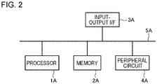
- Fig. 2 is a block diagram illustrating a hardware configuration of the processing system 20.
- the processing system 20 includes a processor 1A, a memory 2A, an input-output interface 3A, a peripheral circuit 4A, and a bus 5A.
- the peripheral circuit 4A includes various modules.
- the peripheral circuit 4A may not be included.
- the processing system 20 may be configured with one physically and/or logically integrated apparatus or may be configured with a plurality of physically and/or logically separated apparatuses. In a case where the processing system 20 is configured with the plurality of physically and/or logically separated apparatuses, each of the plurality of apparatuses can have the hardware configuration.
- the bus 5A is a data transfer path for transmitting and receiving data among the processor 1A, the memory 2A, the peripheral circuit 4A, and the input-output interface 3A.
- the processor 1A is an operation processing device such as a CPU or a graphics processing unit (GPU).
- the memory 2A is a memory such as a random access memory (RAM) or a read only memory (ROM).
- the input-output interface 3A includes an interface for acquiring information from an input device, an external apparatus, an external server, an external sensor, a camera, or the like and an interface for outputting information to an output device, the external apparatus, the external server, or the like.
- the input device is, for example, a keyboard, a mouse, a microphone, a touch panel, a physical button, or a camera.
- the output device is, for example, a display, a speaker, a printer, or a mailer.
- the processor 1A can output an instruction to each module and perform operations based on the operation results of the modules.
- FIG. 3 illustrates one example of a function block diagram of the processing system 20.
- the processing system 20 includes an acquisition unit 21, an extraction unit 22, a comparison unit 23, a biometric detection unit 24, and a storage unit 25.
- the processing system 20 may not include the storage unit 25.
- an external apparatus that is configured to be capable of communicating with the processing system 20 includes the storage unit 25.
- the storage unit 25 stores the reference feature amount indicating the feature of the light emitted by each of the plurality of imaging apparatuses 10 at the time of imaging.
- the plurality of imaging apparatuses 10 include the imaging apparatuses 10 having different makers, model numbers, versions, or the like.
- the imaging apparatuses 10 having different makers, model numbers, versions, or the like may have different characteristics of the light emitted at the time of imaging due to a difference in the number of light sources, the method of arranging the plurality of light sources, the positional relationship between the lens and the light source, the manner of light emission by the plurality of light sources, or the like. Consequently, the characteristics (example: a pattern of light or a position in a pupil) of the reflected light that is reflected in the cornea of the person included in the image may be different. For example, as illustrated in Fig. 4 , the pattern of reflected light q superimposed on a pupil p in the image, the position of the reflected light q in the pupil p, or the like may be different for each imaging apparatus 10.
- the reference feature amount can indicate at least one of the pattern of the reflected light q superimposed on the pupil p in the image and the position of the reflected light q in the pupil p in the image.
- the reference feature amount may indicate the feature of the reflected light q in each of a right eye and a left eye in the image.
- the feature (the position in the pupil or the like) of the reflected light may be different between the right eye and the left eye.
- Fig. 5 schematically illustrates one example of information stored in the storage unit 25.
- imaging apparatus identification information and the reference feature amount are associated with each other.
- the acquisition unit 21 acquires the image generated by each of the plurality of imaging apparatuses 10 and information (imaging apparatus identification information) for identifying the imaging apparatus 10 generating each image.
- the client terminal 2 transmits the image generated by the imaging apparatus 10 corresponding to the own terminal and the imaging apparatus identification information to the server 1.
- the acquisition unit 21 acquires the image and the imaging apparatus identification information transmitted from the client terminal 2.
- acquisition includes at least one of "the own apparatus acquiring data stored in another apparatus or a storage medium (active acquisition)" based on a user input or an instruction of a program, for example, reception by making a request or an inquiry to the other apparatus or accessing the other apparatus or the storage medium and reading, and "the own apparatus inputting data output from the other apparatus into the own apparatus (passive acquisition)” based on the user input or the instruction of the program, for example, waiting in a state where data transmitted from the external apparatus can be received, receiving data transmitted from the external apparatus, receiving data distributed (or transmitted, push-notified, or the like) from the external apparatus, or selective acquisition from the received data or information, and "generating new data by editing data (converting the data into a text, rearranging the data, extracting a part of the data, changing a file format, or the like) and acquiring the new data".
- the extraction unit 22 extracts the feature amount of the light reflected by the cornea of the person from the image generated by the imaging apparatus 10. For example, the extraction unit 22 detects the face of the person included in the image, the eye of the person, the pupil of the person, and the reflected light in the pupil using any image analysis technology such as template matching or edge detection technology. The extraction unit 22 specifies at least one of the pattern of the reflected light superimposed on the pupil and the position of the reflected light in the pupil based on a detection result.
- the comparison unit 23 specifies the imaging apparatus 10 corresponding to the feature amount of the light extracted by the extraction unit 22 based on the feature amount of the light extracted by the extraction unit 22 and the reference feature amount of each of the plurality of imaging apparatuses 10 stored in the storage unit 25.
- the comparison unit 23 may compare the feature amount of the light extracted by the extraction unit 22 with the reference feature amount of each of the plurality of imaging apparatuses 10 stored in the storage unit 25 and specify the reference feature amount matching (having similarity greater than or equal to a predetermined level) the feature amount of the light extracted by the extraction unit 22.
- the comparison unit 23 may specify the imaging apparatus 10 corresponding to the specified reference feature amount as the imaging apparatus 10 corresponding to the feature amount of the light extracted by the extraction unit 22.
- an inference model for inferring the imaging apparatus 10 generating the face image of the person from the feature amount of the light reflected by the cornea of the person may be generated using machine learning based on training data in which each of the plurality of imaging apparatuses 10 is associated with the face image (or the reference feature amount of each imaging apparatus 10) of the person generated by the imaging apparatus 10.
- the comparison unit 23 may obtain an inference result of the imaging apparatus 10 corresponding to the feature amount of the light based on the inference model and the feature amount of the light extracted by the extraction unit 22.
- the "face image” used in the biometric detection in the present application may be an image including the eye of the person and does not necessarily include the entire face of the person.
- Fig. 6 illustrates a summary of the above process.
- a degree of certainty that the image is generated by each imaging apparatus 10 may be shown in the inference result of the inference model.
- the comparison unit 23 may specify the imaging apparatus 10 of which the degree of certainty satisfies a predetermined condition (example: the maximum value and greater than or equal to a threshold) as the imaging apparatus 10 corresponding to the feature amount of the light extracted by the extraction unit 22.
- a predetermined condition example: the maximum value and greater than or equal to a threshold
- the biometric detection unit 24 performs the biometric detection based on a result of whether or not the imaging apparatus 10 generating the image acquired by the acquisition unit 21 matches the imaging apparatus 10 specified by the comparison unit 23.
- the biometric detection unit 24 determines that the image acquired by the acquisition unit 21 is the image obtained from the living body.
- the image obtained from the living body means an image that is generated by imaging the living body by the imaging apparatus 10.
- the biometric detection unit 24 determines that the image acquired by the acquisition unit 21 is not the image obtained from the living body.
- the image not obtained from the living body is, for example, an image generated by imaging a printed matter by the imaging apparatus 10.
- the acquisition unit 21 acquires the image and the imaging apparatus identification information (S10 and S11).
- the extraction unit 22 extracts the feature amount of the light reflected by the cornea of the person from the image acquired in S10 (S12).
- the comparison unit 23 specifies the imaging apparatus 10 corresponding to the feature amount of the light extracted in S12 based on the feature amount of the light extracted in S12 and the reference feature amount of each of the plurality of imaging apparatuses 10 stored in the storage unit 25 (S13).
- the biometric detection unit 24 determines that the image acquired in S10 is the image obtained from the living body (S15). Meanwhile, in a case where the imaging apparatus 10 specified in S13 does not match the imaging apparatus 10 indicated by the imaging apparatus identification information acquired in S11 (No in S14), the biometric detection unit 24 determines that the image acquired in S10 is not the image obtained from the living body (S16).
- a technology enabling biometric detection based on one image is achieved.
- the biometric detection can be performed based on one image, an increase in processing burden of a computer caused by analyzing a plurality of images can be reduced.
- a camera of which the color or the pattern of illumination changes and that is necessary in the case of performing the biometric detection based on a change in corneal reflex does not need to be prepared. Thus, an increase in cost burden can be reduced.
- the plurality of imaging apparatuses 10 randomly or regularly change the light emitted at the time of imaging. For example, one light source emits light at a certain timing, and a plurality of light sources emit light at another timing.
- the processing system 20 acquires light emission type information indicating the type of light emitted by each of the plurality of imaging apparatuses 10 at the time of imaging the person and specifies the imaging apparatus 10 corresponding to the extracted feature amount of the light based on the light emission type information.
- FIG. 3 One example of a function block diagram of the processing system 20 of the present example embodiment is illustrated in Fig. 3 .
- the storage unit 25 stores the reference feature amount indicating the feature of the light emitted by each of the plurality of imaging apparatuses 10 at the time of imaging.
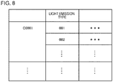
- Fig. 8 schematically illustrates one example of information stored in the storage unit 25.
- the imaging apparatus identification information, a light emission type, and the reference feature amount are associated with each other.
- the storage unit 25 stores variations of a plurality of reference feature amounts of each imaging apparatus 10 in association with the imaging apparatus 10.
- the comparison unit 23 acquires the light emission type information indicating the type of light emitted by each of the plurality of imaging apparatuses 10 at the time of imaging the person.
- the comparison unit 23 may acquire the light emission type information from the imaging apparatus 10 or may calculate the light emission type information based on a predetermined rule.
- the imaging apparatus 10 switches the type of emitted light (hereinafter, may be referred to as the "light emission type") at a predetermined timing or a random timing. Each time the imaging apparatus 10 switches the light emission type, the imaging apparatus 10 notifies the processing system 20 of a new light emission type.
- the comparison unit 23 manages the most recent light emission type of each of the plurality of imaging apparatuses 10 based on the notification from the imaging apparatus 10.
- the predetermined timing may be every certain time such as every 5 minutes, every 30 minutes, every hour, or every day.
- Different light emission types have different methods of light emission by the light source. For example, one light source emits light for a certain light emission type, and a plurality of light sources emit light for another light emission type. Various methods of switching the light emission type are present.
- the imaging apparatus 10 may switch a plurality of light emission types in a predetermined order or may randomly decide a new one from the plurality of light emission types.
- the imaging apparatus 10 may decide the type of light emitted at each imaging timing based on any key and a predetermined calculation rule. For example, any number (example: month, date, time, or minute) included in the date and time of the imaging timing may be set as the key.
- the comparison unit 23 may prestore the calculation rule of each imaging apparatus 10 and calculate the type of light emitted by each of the imaging apparatus 10 at each timing based on the calculation rule and the key acquired by the own system.
- a method of acquiring the light emission type information by the comparison unit 23 is not limited to the above example, and other methods may be employed.
- the comparison unit 23 specifies the imaging apparatus 10 corresponding to the feature amount of the light extracted by the extraction unit 22 based on the acquired light emission type information.
- the comparison unit 23 may compare the feature amount of the light extracted by the extraction unit 22 with the reference feature amount (specified based on the light emission type information) indicating the feature of the light emitted by each of the plurality of imaging apparatuses 10 at the time when the image acquired by the acquisition unit 21 is captured, and specify the reference feature amount matching the feature amount of the light extracted by the extraction unit 22.
- the comparison unit 23 may specify the imaging apparatus 10 corresponding to the specified reference feature amount as the imaging apparatus 10 corresponding to the feature amount of the light extracted by the extraction unit 22.
- an inference model for inferring the imaging apparatus 10 generating the face image of the person from the feature amount of the light reflected by the cornea of the person may be generated using machine learning based on training data in which each of the plurality of imaging apparatuses 10 is associated with the reference feature amount (or the image generated at the time of emitting the light) indicating the feature of the light emitted by each of the plurality of imaging apparatuses 10 at the time of capturing the image acquired by the acquisition unit 21.
- the comparison unit 23 may obtain an inference result of the imaging apparatus 10 corresponding to the feature amount of the light based on the inference model and the feature amount of the light extracted by the extraction unit 22.
- imaging apparatus 10 and the processing system 20 are the same as the first example embodiment.
- the same effect as the first example embodiment is achieved.
- the biometric detection described in the first example embodiment can be performed by randomly or regularly changing the light emitted by the imaging apparatus 10 at the time of imaging, fraudulent activities can be effectively excluded.
- the processing system 20 of the present example embodiment is different from the first and second example embodiments in that the biometric detection is performed based on whether or not the feature amount of the light extracted from the image generated by the first imaging apparatus 10 matches the reference feature amount indicating the feature of the light emitted by the first imaging apparatus 10 at the time of imaging.
- FIG. 3 One example of a function block diagram of the processing system 20 of the present example embodiment is illustrated in Fig. 3 .
- the comparison unit 23 compares the feature amount of the light extracted by the extraction unit 22 with the reference feature amount indicating the feature of the light emitted by the imaging apparatus 10 which is indicated by the imaging apparatus identification information acquired by the acquisition unit 21 at the time of imaging.
- the biometric detection unit 24 performs the biometric detection based on a result of whether or not the feature amount of the light extracted by the extraction unit 22 matches the reference feature amount.
- the biometric detection unit 24 determines that the image acquired by the acquisition unit 21 is the image obtained from the living body. Meanwhile, in a case where the feature amount of the light extracted by the extraction unit 22 does not match the reference feature amount, the biometric detection unit 24 determines that the image acquired by the acquisition unit 21 is not the image obtained from the living body.
- the acquisition unit 21 acquires the image and the imaging apparatus identification information (S20 and S21).
- the comparison unit 23 retrieves the reference feature amount corresponding to the imaging apparatus identification information acquired in S21 from the storage unit 25 (refer to Fig. 5 ) (S22).
- the extraction unit 22 extracts the feature amount of the light reflected by the cornea of the person from the image acquired in S20 (S23).
- the processing order of S22 and S23 is not limited to the illustrated example.
- the comparison unit 23 compares the feature amount of the light extracted in S23 with the reference feature amount acquired in S22 (S24).
- the biometric detection unit 24 determines that the image acquired in S20 is the image obtained from the living body (S26). Meanwhile, in a case where the feature amount of the light extracted in S23 does not match the reference feature amount acquired in S22 (No in S25), the biometric detection unit 24 determines that the image acquired in S20 is not the image obtained from the living body (S27).
- imaging apparatus 10 and the processing system 20 are the same as the first example embodiment.
- the same effect as the first example embodiment is achieved.
- the same effect as the first example embodiment is achieved by a different process from the first example embodiment, the range of design is increased, and such an increase is preferable.
- the plurality of imaging apparatuses 10 randomly or regularly change the light emitted at the time of imaging. For example, one light source emits light at a certain timing, and a plurality of light sources emit light at another timing.
- the processing system 20 acquires the light emission type information indicating the type of light which is emitted by the imaging apparatus 10 generating the image when the acquired image is generated, and performs a comparison process using the reference feature amount indicating the feature of the light indicated by the light emission type information.
- FIG. 3 One example of a function block diagram of the processing system 20 of the present example embodiment is illustrated in Fig. 3 .
- the storage unit 25 stores the reference feature amount indicating the feature of the light emitted by each of the plurality of imaging apparatuses 10 at the time of imaging.
- Fig. 8 schematically illustrates one example of information stored in the storage unit 25.
- the imaging apparatus identification information, the light emission type, and the reference feature amount are associated with each other.
- the storage unit 25 stores variations of a plurality of reference feature amounts of each imaging apparatus 10 in association with the imaging apparatus 10.
- the comparison unit 23 acquires the light emission type information indicating the type of light which is emitted by the imaging apparatus 10 generating the image when (at the time of imaging) the image acquired by the acquisition unit 21 is generated.
- a method of acquiring the light emission type information by the comparison unit 23 is the same as described in the second example embodiment.
- the comparison unit 23 compares the feature amount of the light extracted by the extraction unit 22 with the reference feature amount indicating the feature of the light indicated by the acquired light emission type information.
- the acquisition unit 21 acquires the image and the imaging apparatus identification information (S30 and S31).
- the comparison unit 23 acquires the light emission type information indicating the type of light emitted by the imaging apparatus 10 at the time of generating the image acquired in S30 (S32).
- the comparison unit 23 retrieves the imaging apparatus identification information acquired in S31 and the reference feature amount corresponding to the light emission type information acquired in S32 from the storage unit 25 (refer to Fig. 8 ) (S33).
- the extraction unit 22 extracts the feature amount of the light reflected by the cornea of the person from the image acquired in S30 (S34).
- the processing order of S32, S33, and S34 is not limited to the illustrated example.
- the comparison unit 23 compares the feature amount of the light extracted in S34 with the reference feature amount acquired in S33 (S35).
- the biometric detection unit 24 determines that the image acquired in S30 is the image obtained from the living body (S37). Meanwhile, in a case where the feature amount of the light extracted in S34 does not match the reference feature amount acquired in S33 (No in S36), the biometric detection unit 24 determines that the image acquired in S30 is not the image obtained from the living body (S38).
- imaging apparatus 10 and the processing system 20 are the same as the third example embodiment.
- the same effect as the third example embodiment is achieved.
- the biometric detection described in the third example embodiment can be performed by randomly or regularly changing the light emitted by the imaging apparatus 10 at the time of imaging, fraudulent activities can be effectively excluded.
- biometric detection in which the "biometric detection process of any of the first to fourth example embodiments" and a “biometric detection process based on a plurality of images generated by imaging the same person a plurality of times by changing the light emitted by the imaging apparatus 10" are combined is performed.
- biometric detection process of any of the first to fourth example embodiments and a “biometric detection process based on a plurality of images generated by imaging the same person a plurality of times by changing the light emitted by the imaging apparatus 10" are combined is performed.
- FIG. 3 One example of a function block diagram of the processing system 20 of the present example embodiment is illustrated in Fig. 3 .
- the imaging apparatus 10 images the same person a plurality of times by changing the emitted light and generates a plurality of images including the same person. For example, imaging is performed by causing one light source to emit light at a certain timing, and imaging is performed by causing another light source (or a plurality of light sources) to emit light at another timing.
- the extraction unit 22 extracts the feature amount of the light reflected by the cornea of the person from each of the plurality of images.
- the comparison unit 23 compares the feature amounts of the light extracted from the plurality of images including the same person with each other.
- the biometric detection unit 24 performs the biometric detection based on the feature amount of the light extracted from each of the plurality of images including the same person. Specifically, the biometric detection unit 24 performs the biometric detection based on a result of whether or not the feature amounts of the light extracted from the plurality of images satisfy a predetermined relationship.
- the predetermined relationship is "the feature amounts of the light extracted from the plurality of images do not match each other", "a relative relationship between light emission positions indicated by the feature amounts of the light extracted from the plurality of images satisfies a predetermined relationship", or the like but is not limited thereto.
- the position of the reflected light in the pupil in the image generated at the certain timing is different from the position of the reflected light in the pupil in the image generated at the other timing on the assumption that a subject almost does not move between the two very short timings.
- the relative relationship can be calculated based on a relative positional relationship between two light sources, a relative positional relationship among the camera, the light source, and the subject, or the like.
- the acquisition unit 21 acquires the plurality of images and the imaging apparatus identification information (S40 and S41).
- the acquisition unit 21 acquires an image captured at an earlier timing and an image captured at a later timing.
- the type of light emitted by the imaging apparatus 10 is different between the earlier imaging timing and the later imaging timing.
- the extraction unit 22 extracts the feature amount of the light reflected by the cornea of the person from each of the plurality of images acquired in S40 (S42).
- the comparison unit 23 specifies the imaging apparatus 10 corresponding to the feature amount of the light extracted in S42 based on the feature amount of the light extracted from the image captured at the earlier timing and the reference feature amount (reference feature amount indicating the feature of the light emitted at the time of imaging at the earlier timing) of each of the plurality of imaging apparatuses 10 stored in the storage unit 25 (S43).
- the type of light emitted at the earlier timing may be decided in advance for each imaging apparatus 10, and information about the type of light may be stored in the processing system 20. In this process, the "earlier timing" may be replaced with the "later timing".
- the comparison unit 23 determines whether or not the feature amount of the light extracted from the image captured at the earlier timing and the feature amount of the light extracted from the image captured at the later timing satisfy the predetermined relationship (S45).
- the predetermined relationship is described above.
- the biometric detection unit 24 determines that the image acquired in S40 is the image obtained from the living body (S47).
- the biometric detection unit 24 determines that the image acquired in S40 is not the image obtained from the living body (S48).
- S40 to S43 may be replaced with S20 to S25 in Fig. 9 or S30 to S36 in Fig. 10 .
- imaging apparatus 10 and the processing system 20 are the same as any of the first to fourth example embodiments.
- the accuracy of the biometric detection is improved by combining a plurality of biometric detection processes.
- the imaging apparatus 10 and the processing system 20 of the present example embodiment are in a one-on-one relationship as illustrated in Fig. 12 .
- the imaging apparatus 10 and the processing system 20 may be physically and/or logically separated or may be physically and/or logically integrated.
- the storage unit 25 of the processing system 20 stores only the reference feature amount of the corresponding imaging apparatus 10.
- the acquisition unit 21 does not need to acquire the imaging apparatus identification information.
- Other configurations of the imaging apparatus 10 and the processing system 20 are the same as any of the first to fourth example embodiments.
- the same effect as the first to fifth example embodiments can be achieved.
- the processing system 20 may accumulate the image acquired from each imaging apparatus 10 in association with the imaging apparatus identification information of each imaging apparatus 10. Accumulated data may be used as the training data for generating the inference model (refer to Fig. 6 ).
Landscapes
- Engineering & Computer Science (AREA)
- Physics & Mathematics (AREA)
- Theoretical Computer Science (AREA)
- Multimedia (AREA)
- General Physics & Mathematics (AREA)
- Human Computer Interaction (AREA)
- Health & Medical Sciences (AREA)
- Ophthalmology & Optometry (AREA)
- General Health & Medical Sciences (AREA)
- Software Systems (AREA)
- Computer Vision & Pattern Recognition (AREA)
- Collating Specific Patterns (AREA)
- Image Analysis (AREA)
- Measurement Of The Respiration, Hearing Ability, Form, And Blood Characteristics Of Living Organisms (AREA)
- Accessory Devices And Overall Control Thereof (AREA)
- Studio Devices (AREA)
Abstract
Description
- The example embodiments relates to a processing system, a processing method, and a program.
- In biometric authentication using an iris image, a face image, or the like, biometric detection technology may be used. Patent Document 1 discloses a technology for performing biometric detection based on a change in corneal reflex accompanied by movement of a camera. In addition, Patent Document 1 discloses that the biometric detection may also be performed based on the corneal reflex that is changed by changing the color or a pattern of illumination.
- [Patent Document 1]
Japanese Patent Application Publication No. 2018-504703 - In the case of the technology disclosed in Patent Document 1 for performing the biometric detection based on a change in corneal reflex, a plurality of images are required, and the biometric detection cannot be performed based on one image. An object of the example embodiments is to provide a technology enabling biometric detection based on one image.
- In one example embodiment, there is provided a processing system including an extraction unit that extracts a feature amount of light reflected by a cornea of a person from an image generated by a first imaging apparatus, a comparison unit that specifies an imaging apparatus corresponding to the extracted feature amount of the light based on the extracted feature amount of the light and a reference feature amount indicating a feature of light emitted by each of a plurality of imaging apparatuses at a time of imaging, and a biometric detection unit that performs biometric detection based on a result of whether or not the first imaging apparatus matches the specified imaging apparatus.
- In another example embodiment, there is provided a processing system including an extraction unit that extracts a feature amount of light reflected by a cornea of a person from an image generated by a first imaging apparatus, a comparison unit that compares the extracted feature amount of the light with a reference feature amount indicating a feature of light emitted by the first imaging apparatus at a time of imaging, and a biometric detection unit that performs biometric detection based on a result of whether or not the extracted feature amount of the light matches the reference feature amount.
- In another example embodiment, there is provided a processing method executed by a computer, the method including extracting a feature amount of light reflected by a cornea of a person from an image generated by a first imaging apparatus, specifying an imaging apparatus corresponding to the extracted feature amount of the light based on the extracted feature amount of the light and a reference feature amount indicating a feature of light emitted by each of a plurality of imaging apparatuses at a time of imaging, and performing biometric detection based on a result of whether or not the first imaging apparatus matches the specified imaging apparatus.
- In another example embodiment, there is provided a processing method executed by a computer, the method including extracting a feature amount of light reflected by a cornea of a person from an image generated by a first imaging apparatus, comparing the extracted feature amount of the light with a reference feature amount indicating a feature of light emitted by the first imaging apparatus at a time of imaging, and performing biometric detection based on a result of whether or not the extracted feature amount of the light matches the reference feature amount.
- In another example embodiment, there is provided a program causing a computer to function as an extraction unit that extracts a feature amount of light reflected by a cornea of a person from an image generated by a first imaging apparatus, a comparison unit that specifies an imaging apparatus corresponding to the extracted feature amount of the light based on the extracted feature amount of the light and a reference feature amount indicating a feature of light emitted by each of a plurality of imaging apparatuses at a time of imaging, and a biometric detection unit that performs biometric detection based on a result of whether or not the first imaging apparatus matches the specified imaging apparatus.
- In another example embodiment, there is provided a program causing a computer to function as an extraction unit that extracts a feature amount of light reflected by a cornea of a person from an image generated by a first imaging apparatus, a comparison unit that compares the extracted feature amount of the light with a reference feature amount indicating a feature of light emitted by the first imaging apparatus at a time of imaging, and a biometric detection unit that performs biometric detection based on a result of whether or not the extracted feature amount of the light matches the reference feature amount.
-
-
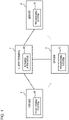
Fig. 1 is a function block diagram for describing one example of a relationship between an imaging apparatus and a processing system of the present example embodiment. -
Fig. 2 is a diagram illustrating one example of a hardware configuration of the processing system of the present example embodiment. -
Fig. 3 is one example of a function block diagram of the processing system of the present example embodiment. -
Fig. 4 is a diagram for describing an effect of the processing system of the present example embodiment. -
Fig. 5 is a diagram schematically illustrating one example of information processed by the processing system of the present example embodiment. -
Fig. 6 is a diagram for describing one example of a process of the processing system of the present example embodiment. -
Fig. 7 is a flowchart illustrating one example of a flow of process of the processing system of the present example embodiment. -
Fig. 8 is a diagram schematically illustrating one example of the information processed by the processing system of the present example embodiment. -
Fig. 9 is a flowchart illustrating one example of the flow of process of the processing system of the present example embodiment. -
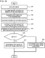
Fig. 10 is a flowchart illustrating one example of the flow of process of the processing system of the present example embodiment. -
Fig. 11 is a flowchart illustrating one example of the flow of process of the processing system of the present example embodiment. -
Fig. 12 is a function block diagram for describing one example of the relationship between the imaging apparatus and the processing system of the present example embodiment. - First, an overall perspective and a summary of the present example embodiment will be described using
Fig. 1 . As illustrated, the present example embodiment employs a server-client system. A server 1 performs biometric authentication based on an iris image or a face image acquired from aclient terminal 2 and biometric detection based on an image of a cornea part (hereinafter, a "cornea image"). For theclient terminal 2 that succeeds in passing the biometric authentication and for which it is determined that the image is obtained from a living body, the server 1 permits theclient terminal 2 to perform a predetermined process. The predetermined process is logging in to the server 1 or the like but is not limited thereto. - The biometric authentication of the present example embodiment is implemented by employing any technology.
- A summary of the biometric detection of the present example embodiment is as follows. First,
imaging apparatuses 10 respectively disposed in a plurality ofclient terminals 2 includeimaging apparatuses 10 having different makers, model numbers, versions, or the like. The plurality ofimaging apparatuses 10 may includeimaging apparatuses 10 having an identical maker, model number, version, or the like. Theimaging apparatuses 10 having different makers, model numbers, versions, or the like may have different characteristics of light emitted at the time of imaging due to a difference in the number of light sources, a method of arranging a plurality of light sources, a positional relationship between a lens and a light source, a method of light emission by the plurality of light sources, or the like. Consequently, characteristics (example: a pattern of light or a position in a pupil) of reflected light that is reflected in the cornea of a person included in the image may be different. Light emitted by a light source of theimaging apparatus 10 is desirably infrared light but may be other light. - In a case where the living body is imaged by the
imaging apparatus 10, the characteristics of the light reflected by the cornea of the person included in the generated image originate from theimaging apparatus 10. Meanwhile, in a case where a non-living body, for example, an image (printed matter) generated by anotherimaging apparatus 10, is imaged by theimaging apparatus 10, the characteristics of light reflected by the cornea of the person included in the generated image originate from theother imaging apparatus 10. - The
processing system 20 of the present example embodiment performs the biometric detection based on such characteristics. Specifically, in a case where theprocessing system 20 extracts a feature amount of the light reflected by the cornea of the person from the image generated by afirst imaging apparatus 10, theprocessing system 20 compares the extracted feature amount of the light with a reference feature amount indicating characteristics of the light emitted by each of the plurality ofimaging apparatuses 10 at the time of imaging, and specifies theimaging apparatus 10 corresponding to the extracted feature amount of the light. In a case where thefirst imaging apparatus 10 matches thespecified imaging apparatus 10, theprocessing system 20 determines that the image is obtained from the living body. In the case of non-matching, theprocessing system 20 determines that the image is not obtained from the living body. - Next, a configuration of the
processing system 20 of the present example embodiment will be described in detail. First, one example of a hardware configuration of theprocessing system 20 will be described. Each function of theprocessing system 20 is implemented by any combination of hardware and software mainly based on a central processing unit (CPU) of any computer, a memory, a program loaded in the memory, a storage unit (can store not only a program stored in advance from a step of shipping the apparatus but also a program downloaded from a storage medium such as a compact disc (CD) or a server or the like on the Internet) such as a hard disk storing the program, and an interface for network connection. Those skilled in the art may understand that various modification examples are present for the implementation method and the apparatus. -
Fig. 2 is a block diagram illustrating a hardware configuration of theprocessing system 20. As illustrated inFig. 2 , theprocessing system 20 includes aprocessor 1A, amemory 2A, an input-output interface 3A, aperipheral circuit 4A, and abus 5A. Theperipheral circuit 4A includes various modules. Theperipheral circuit 4A may not be included. Theprocessing system 20 may be configured with one physically and/or logically integrated apparatus or may be configured with a plurality of physically and/or logically separated apparatuses. In a case where theprocessing system 20 is configured with the plurality of physically and/or logically separated apparatuses, each of the plurality of apparatuses can have the hardware configuration. - The
bus 5A is a data transfer path for transmitting and receiving data among theprocessor 1A, thememory 2A, theperipheral circuit 4A, and the input-output interface 3A. Theprocessor 1A is an operation processing device such as a CPU or a graphics processing unit (GPU). Thememory 2A is a memory such as a random access memory (RAM) or a read only memory (ROM). The input-output interface 3A includes an interface for acquiring information from an input device, an external apparatus, an external server, an external sensor, a camera, or the like and an interface for outputting information to an output device, the external apparatus, the external server, or the like. The input device is, for example, a keyboard, a mouse, a microphone, a touch panel, a physical button, or a camera. The output device is, for example, a display, a speaker, a printer, or a mailer. Theprocessor 1A can output an instruction to each module and perform operations based on the operation results of the modules. - Next, one example of a functional configuration of the
processing system 20 will be described.Fig. 3 illustrates one example of a function block diagram of theprocessing system 20. As illustrated, theprocessing system 20 includes anacquisition unit 21, anextraction unit 22, acomparison unit 23, abiometric detection unit 24, and astorage unit 25. Theprocessing system 20 may not include thestorage unit 25. In this case, an external apparatus that is configured to be capable of communicating with theprocessing system 20 includes thestorage unit 25. - The
storage unit 25 stores the reference feature amount indicating the feature of the light emitted by each of the plurality ofimaging apparatuses 10 at the time of imaging. - As described above, the plurality of
imaging apparatuses 10 include theimaging apparatuses 10 having different makers, model numbers, versions, or the like. The imaging apparatuses 10 having different makers, model numbers, versions, or the like may have different characteristics of the light emitted at the time of imaging due to a difference in the number of light sources, the method of arranging the plurality of light sources, the positional relationship between the lens and the light source, the manner of light emission by the plurality of light sources, or the like. Consequently, the characteristics (example: a pattern of light or a position in a pupil) of the reflected light that is reflected in the cornea of the person included in the image may be different. For example, as illustrated inFig. 4 , the pattern of reflected light q superimposed on a pupil p in the image, the position of the reflected light q in the pupil p, or the like may be different for eachimaging apparatus 10. - The reference feature amount can indicate at least one of the pattern of the reflected light q superimposed on the pupil p in the image and the position of the reflected light q in the pupil p in the image. In addition, the reference feature amount may indicate the feature of the reflected light q in each of a right eye and a left eye in the image. The feature (the position in the pupil or the like) of the reflected light may be different between the right eye and the left eye.
-
Fig. 5 schematically illustrates one example of information stored in thestorage unit 25. In the illustrated example, imaging apparatus identification information and the reference feature amount are associated with each other. - Returning to
Fig. 3 , theacquisition unit 21 acquires the image generated by each of the plurality ofimaging apparatuses 10 and information (imaging apparatus identification information) for identifying theimaging apparatus 10 generating each image. For example, the client terminal 2 (refer toFig. 1 ) transmits the image generated by theimaging apparatus 10 corresponding to the own terminal and the imaging apparatus identification information to the server 1. Theacquisition unit 21 acquires the image and the imaging apparatus identification information transmitted from theclient terminal 2. - In the present specification, "acquisition" includes at least one of "the own apparatus acquiring data stored in another apparatus or a storage medium (active acquisition)" based on a user input or an instruction of a program, for example, reception by making a request or an inquiry to the other apparatus or accessing the other apparatus or the storage medium and reading, and "the own apparatus inputting data output from the other apparatus into the own apparatus (passive acquisition)" based on the user input or the instruction of the program, for example, waiting in a state where data transmitted from the external apparatus can be received, receiving data transmitted from the external apparatus, receiving data distributed (or transmitted, push-notified, or the like) from the external apparatus, or selective acquisition from the received data or information, and "generating new data by editing data (converting the data into a text, rearranging the data, extracting a part of the data, changing a file format, or the like) and acquiring the new data".
- The
extraction unit 22 extracts the feature amount of the light reflected by the cornea of the person from the image generated by theimaging apparatus 10. For example, theextraction unit 22 detects the face of the person included in the image, the eye of the person, the pupil of the person, and the reflected light in the pupil using any image analysis technology such as template matching or edge detection technology. Theextraction unit 22 specifies at least one of the pattern of the reflected light superimposed on the pupil and the position of the reflected light in the pupil based on a detection result. - The
comparison unit 23 specifies theimaging apparatus 10 corresponding to the feature amount of the light extracted by theextraction unit 22 based on the feature amount of the light extracted by theextraction unit 22 and the reference feature amount of each of the plurality ofimaging apparatuses 10 stored in thestorage unit 25. - For example, the
comparison unit 23 may compare the feature amount of the light extracted by theextraction unit 22 with the reference feature amount of each of the plurality ofimaging apparatuses 10 stored in thestorage unit 25 and specify the reference feature amount matching (having similarity greater than or equal to a predetermined level) the feature amount of the light extracted by theextraction unit 22. Thecomparison unit 23 may specify theimaging apparatus 10 corresponding to the specified reference feature amount as theimaging apparatus 10 corresponding to the feature amount of the light extracted by theextraction unit 22. - Besides, an inference model for inferring the
imaging apparatus 10 generating the face image of the person from the feature amount of the light reflected by the cornea of the person may be generated using machine learning based on training data in which each of the plurality ofimaging apparatuses 10 is associated with the face image (or the reference feature amount of each imaging apparatus 10) of the person generated by theimaging apparatus 10. Thecomparison unit 23 may obtain an inference result of theimaging apparatus 10 corresponding to the feature amount of the light based on the inference model and the feature amount of the light extracted by theextraction unit 22. The "face image" used in the biometric detection in the present application may be an image including the eye of the person and does not necessarily include the entire face of the person. -
Fig. 6 illustrates a summary of the above process. As illustrated, a degree of certainty that the image is generated by eachimaging apparatus 10 may be shown in the inference result of the inference model. Thecomparison unit 23 may specify theimaging apparatus 10 of which the degree of certainty satisfies a predetermined condition (example: the maximum value and greater than or equal to a threshold) as theimaging apparatus 10 corresponding to the feature amount of the light extracted by theextraction unit 22. - Returning to
Fig. 3 , thebiometric detection unit 24 performs the biometric detection based on a result of whether or not theimaging apparatus 10 generating the image acquired by theacquisition unit 21 matches theimaging apparatus 10 specified by thecomparison unit 23. - Specifically, in a case where the
imaging apparatus 10 generating the image acquired by theacquisition unit 21 matches theimaging apparatus 10 specified by thecomparison unit 23, thebiometric detection unit 24 determines that the image acquired by theacquisition unit 21 is the image obtained from the living body. The image obtained from the living body means an image that is generated by imaging the living body by theimaging apparatus 10. - Meanwhile, in a case where the
imaging apparatus 10 generating the image acquired by theacquisition unit 21 does not match theimaging apparatus 10 specified by thecomparison unit 23, thebiometric detection unit 24 determines that the image acquired by theacquisition unit 21 is not the image obtained from the living body. The image not obtained from the living body is, for example, an image generated by imaging a printed matter by theimaging apparatus 10. - Next, one example of a flow of process of the
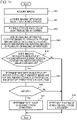
processing system 20 will be described using the flowchart inFig. 7 . Details of the process performed by each function unit are described above and thus, will not be repeated here. - First, the
acquisition unit 21 acquires the image and the imaging apparatus identification information (S10 and S11). Theextraction unit 22 extracts the feature amount of the light reflected by the cornea of the person from the image acquired in S10 (S12). - Next, the
comparison unit 23 specifies theimaging apparatus 10 corresponding to the feature amount of the light extracted in S12 based on the feature amount of the light extracted in S12 and the reference feature amount of each of the plurality ofimaging apparatuses 10 stored in the storage unit 25 (S13). - In a case where the
imaging apparatus 10 specified in S13 matches theimaging apparatus 10 indicated by the imaging apparatus identification information acquired in S11 (Yes in S14), thebiometric detection unit 24 determines that the image acquired in S10 is the image obtained from the living body (S15). Meanwhile, in a case where theimaging apparatus 10 specified in S13 does not match theimaging apparatus 10 indicated by the imaging apparatus identification information acquired in S11 (No in S14), thebiometric detection unit 24 determines that the image acquired in S10 is not the image obtained from the living body (S16). - According to the
imaging apparatus 10 and theprocessing system 20 of the present example embodiment, a technology enabling biometric detection based on one image is achieved. In addition, since the biometric detection can be performed based on one image, an increase in processing burden of a computer caused by analyzing a plurality of images can be reduced. In addition, a camera of which the color or the pattern of illumination changes and that is necessary in the case of performing the biometric detection based on a change in corneal reflex does not need to be prepared. Thus, an increase in cost burden can be reduced. - In the present example embodiment, the plurality of
imaging apparatuses 10 randomly or regularly change the light emitted at the time of imaging. For example, one light source emits light at a certain timing, and a plurality of light sources emit light at another timing. - The
processing system 20 acquires light emission type information indicating the type of light emitted by each of the plurality ofimaging apparatuses 10 at the time of imaging the person and specifies theimaging apparatus 10 corresponding to the extracted feature amount of the light based on the light emission type information. Hereinafter, details will be described. - One example of a function block diagram of the
processing system 20 of the present example embodiment is illustrated inFig. 3 . - The
storage unit 25 stores the reference feature amount indicating the feature of the light emitted by each of the plurality ofimaging apparatuses 10 at the time of imaging.Fig. 8 schematically illustrates one example of information stored in thestorage unit 25. In the illustrated example, the imaging apparatus identification information, a light emission type, and the reference feature amount are associated with each other. As illustrated, thestorage unit 25 stores variations of a plurality of reference feature amounts of eachimaging apparatus 10 in association with theimaging apparatus 10. - The
comparison unit 23 acquires the light emission type information indicating the type of light emitted by each of the plurality ofimaging apparatuses 10 at the time of imaging the person. Thecomparison unit 23 may acquire the light emission type information from theimaging apparatus 10 or may calculate the light emission type information based on a predetermined rule. - For example, the
imaging apparatus 10 switches the type of emitted light (hereinafter, may be referred to as the "light emission type") at a predetermined timing or a random timing. Each time theimaging apparatus 10 switches the light emission type, theimaging apparatus 10 notifies theprocessing system 20 of a new light emission type. Thecomparison unit 23 manages the most recent light emission type of each of the plurality ofimaging apparatuses 10 based on the notification from theimaging apparatus 10. - The predetermined timing may be every certain time such as every 5 minutes, every 30 minutes, every hour, or every day. Different light emission types have different methods of light emission by the light source. For example, one light source emits light for a certain light emission type, and a plurality of light sources emit light for another light emission type. Various methods of switching the light emission type are present. For example, the
imaging apparatus 10 may switch a plurality of light emission types in a predetermined order or may randomly decide a new one from the plurality of light emission types. - Besides, the
imaging apparatus 10 may decide the type of light emitted at each imaging timing based on any key and a predetermined calculation rule. For example, any number (example: month, date, time, or minute) included in the date and time of the imaging timing may be set as the key. Thecomparison unit 23 may prestore the calculation rule of eachimaging apparatus 10 and calculate the type of light emitted by each of theimaging apparatus 10 at each timing based on the calculation rule and the key acquired by the own system. - A method of acquiring the light emission type information by the
comparison unit 23 is not limited to the above example, and other methods may be employed. - The
comparison unit 23 specifies theimaging apparatus 10 corresponding to the feature amount of the light extracted by theextraction unit 22 based on the acquired light emission type information. - For example, the
comparison unit 23 may compare the feature amount of the light extracted by theextraction unit 22 with the reference feature amount (specified based on the light emission type information) indicating the feature of the light emitted by each of the plurality ofimaging apparatuses 10 at the time when the image acquired by theacquisition unit 21 is captured, and specify the reference feature amount matching the feature amount of the light extracted by theextraction unit 22. Thecomparison unit 23 may specify theimaging apparatus 10 corresponding to the specified reference feature amount as theimaging apparatus 10 corresponding to the feature amount of the light extracted by theextraction unit 22. - Besides, an inference model for inferring the
imaging apparatus 10 generating the face image of the person from the feature amount of the light reflected by the cornea of the person may be generated using machine learning based on training data in which each of the plurality ofimaging apparatuses 10 is associated with the reference feature amount (or the image generated at the time of emitting the light) indicating the feature of the light emitted by each of the plurality ofimaging apparatuses 10 at the time of capturing the image acquired by theacquisition unit 21. Thecomparison unit 23 may obtain an inference result of theimaging apparatus 10 corresponding to the feature amount of the light based on the inference model and the feature amount of the light extracted by theextraction unit 22. - Other configurations of the
imaging apparatus 10 and theprocessing system 20 are the same as the first example embodiment. - According to the
imaging apparatus 10 and theprocessing system 20 of the present example embodiment, the same effect as the first example embodiment is achieved. In addition, since the biometric detection described in the first example embodiment can be performed by randomly or regularly changing the light emitted by theimaging apparatus 10 at the time of imaging, fraudulent activities can be effectively excluded. - The
processing system 20 of the present example embodiment is different from the first and second example embodiments in that the biometric detection is performed based on whether or not the feature amount of the light extracted from the image generated by thefirst imaging apparatus 10 matches the reference feature amount indicating the feature of the light emitted by thefirst imaging apparatus 10 at the time of imaging. - One example of a function block diagram of the
processing system 20 of the present example embodiment is illustrated inFig. 3 . - The
comparison unit 23 compares the feature amount of the light extracted by theextraction unit 22 with the reference feature amount indicating the feature of the light emitted by theimaging apparatus 10 which is indicated by the imaging apparatus identification information acquired by theacquisition unit 21 at the time of imaging. - The
biometric detection unit 24 performs the biometric detection based on a result of whether or not the feature amount of the light extracted by theextraction unit 22 matches the reference feature amount. - Specifically, in a case where the feature amount of the light extracted by the
extraction unit 22 matches the reference feature amount, thebiometric detection unit 24 determines that the image acquired by theacquisition unit 21 is the image obtained from the living body. Meanwhile, in a case where the feature amount of the light extracted by theextraction unit 22 does not match the reference feature amount, thebiometric detection unit 24 determines that the image acquired by theacquisition unit 21 is not the image obtained from the living body. - Next, one example of a flow of process of the
processing system 20 will be described using the flowchart inFig. 9 . Details of the process performed by each function unit are described above and thus, will not be repeated here. - First, the
acquisition unit 21 acquires the image and the imaging apparatus identification information (S20 and S21). Thecomparison unit 23 retrieves the reference feature amount corresponding to the imaging apparatus identification information acquired in S21 from the storage unit 25 (refer toFig. 5 ) (S22). Theextraction unit 22 extracts the feature amount of the light reflected by the cornea of the person from the image acquired in S20 (S23). The processing order of S22 and S23 is not limited to the illustrated example. - Next, the
comparison unit 23 compares the feature amount of the light extracted in S23 with the reference feature amount acquired in S22 (S24). - In a case where the feature amount of the light extracted in S23 matches the reference feature amount acquired in S22 (Yes in S25), the
biometric detection unit 24 determines that the image acquired in S20 is the image obtained from the living body (S26). Meanwhile, in a case where the feature amount of the light extracted in S23 does not match the reference feature amount acquired in S22 (No in S25), thebiometric detection unit 24 determines that the image acquired in S20 is not the image obtained from the living body (S27). - Other configurations of the
imaging apparatus 10 and theprocessing system 20 are the same as the first example embodiment. - According to the
imaging apparatus 10 and theprocessing system 20 of the present example embodiment, the same effect as the first example embodiment is achieved. In addition, since the same effect as the first example embodiment is achieved by a different process from the first example embodiment, the range of design is increased, and such an increase is preferable. - In the present example embodiment, the plurality of
imaging apparatuses 10 randomly or regularly change the light emitted at the time of imaging. For example, one light source emits light at a certain timing, and a plurality of light sources emit light at another timing. - The
processing system 20 acquires the light emission type information indicating the type of light which is emitted by theimaging apparatus 10 generating the image when the acquired image is generated, and performs a comparison process using the reference feature amount indicating the feature of the light indicated by the light emission type information. Hereinafter, details will be described. - One example of a function block diagram of the
processing system 20 of the present example embodiment is illustrated inFig. 3 . - The
storage unit 25 stores the reference feature amount indicating the feature of the light emitted by each of the plurality ofimaging apparatuses 10 at the time of imaging.Fig. 8 schematically illustrates one example of information stored in thestorage unit 25. In the illustrated example, the imaging apparatus identification information, the light emission type, and the reference feature amount are associated with each other. As illustrated, thestorage unit 25 stores variations of a plurality of reference feature amounts of eachimaging apparatus 10 in association with theimaging apparatus 10. - The
comparison unit 23 acquires the light emission type information indicating the type of light which is emitted by theimaging apparatus 10 generating the image when (at the time of imaging) the image acquired by theacquisition unit 21 is generated. A method of acquiring the light emission type information by thecomparison unit 23 is the same as described in the second example embodiment. - The
comparison unit 23 compares the feature amount of the light extracted by theextraction unit 22 with the reference feature amount indicating the feature of the light indicated by the acquired light emission type information. - Next, one example of a flow of process of the
processing system 20 will be described using the flowchart inFig. 10 . Details of the process performed by each function unit are described above and thus, will not be repeated here. - First, the
acquisition unit 21 acquires the image and the imaging apparatus identification information (S30 and S31). Next, thecomparison unit 23 acquires the light emission type information indicating the type of light emitted by theimaging apparatus 10 at the time of generating the image acquired in S30 (S32). Thecomparison unit 23 retrieves the imaging apparatus identification information acquired in S31 and the reference feature amount corresponding to the light emission type information acquired in S32 from the storage unit 25 (refer toFig. 8 ) (S33). Theextraction unit 22 extracts the feature amount of the light reflected by the cornea of the person from the image acquired in S30 (S34). The processing order of S32, S33, and S34 is not limited to the illustrated example. - Next, the
comparison unit 23 compares the feature amount of the light extracted in S34 with the reference feature amount acquired in S33 (S35). - In a case where the feature amount of the light extracted in S34 matches the reference feature amount acquired in S33 (Yes in S36), the
biometric detection unit 24 determines that the image acquired in S30 is the image obtained from the living body (S37). Meanwhile, in a case where the feature amount of the light extracted in S34 does not match the reference feature amount acquired in S33 (No in S36), thebiometric detection unit 24 determines that the image acquired in S30 is not the image obtained from the living body (S38). - Other configurations of the
imaging apparatus 10 and theprocessing system 20 are the same as the third example embodiment. - According to the
imaging apparatus 10 and theprocessing system 20 of the present example embodiment, the same effect as the third example embodiment is achieved. In addition, since the biometric detection described in the third example embodiment can be performed by randomly or regularly changing the light emitted by theimaging apparatus 10 at the time of imaging, fraudulent activities can be effectively excluded. - In the present example embodiment, biometric detection in which the "biometric detection process of any of the first to fourth example embodiments" and a "biometric detection process based on a plurality of images generated by imaging the same person a plurality of times by changing the light emitted by the
imaging apparatus 10" are combined is performed. Hereinafter, details will be described. - One example of a function block diagram of the
processing system 20 of the present example embodiment is illustrated inFig. 3 . - In the present example embodiment, the
imaging apparatus 10 images the same person a plurality of times by changing the emitted light and generates a plurality of images including the same person. For example, imaging is performed by causing one light source to emit light at a certain timing, and imaging is performed by causing another light source (or a plurality of light sources) to emit light at another timing. - The
extraction unit 22 extracts the feature amount of the light reflected by the cornea of the person from each of the plurality of images. - The
comparison unit 23 compares the feature amounts of the light extracted from the plurality of images including the same person with each other. - The
biometric detection unit 24 performs the biometric detection based on the feature amount of the light extracted from each of the plurality of images including the same person. Specifically, thebiometric detection unit 24 performs the biometric detection based on a result of whether or not the feature amounts of the light extracted from the plurality of images satisfy a predetermined relationship. The predetermined relationship is "the feature amounts of the light extracted from the plurality of images do not match each other", "a relative relationship between light emission positions indicated by the feature amounts of the light extracted from the plurality of images satisfies a predetermined relationship", or the like but is not limited thereto. - For example, in a case where imaging is performed by causing one light source to emit light at a certain timing and imaging is performed by causing another light source to emit light at another timing, the position of the reflected light in the pupil in the image generated at the certain timing is different from the position of the reflected light in the pupil in the image generated at the other timing on the assumption that a subject almost does not move between the two very short timings. The relative relationship can be calculated based on a relative positional relationship between two light sources, a relative positional relationship among the camera, the light source, and the subject, or the like.
- Next, one example of a flow of process of the
processing system 20 will be described using the flowchart inFig. 11 . Details of the process performed by each function unit are described above and thus, will not be repeated here. - First, the
acquisition unit 21 acquires the plurality of images and the imaging apparatus identification information (S40 and S41). Here, theacquisition unit 21 acquires an image captured at an earlier timing and an image captured at a later timing. The type of light emitted by theimaging apparatus 10 is different between the earlier imaging timing and the later imaging timing. Theextraction unit 22 extracts the feature amount of the light reflected by the cornea of the person from each of the plurality of images acquired in S40 (S42). - Next, the
comparison unit 23 specifies theimaging apparatus 10 corresponding to the feature amount of the light extracted in S42 based on the feature amount of the light extracted from the image captured at the earlier timing and the reference feature amount (reference feature amount indicating the feature of the light emitted at the time of imaging at the earlier timing) of each of the plurality ofimaging apparatuses 10 stored in the storage unit 25 (S43). The type of light emitted at the earlier timing may be decided in advance for eachimaging apparatus 10, and information about the type of light may be stored in theprocessing system 20. In this process, the "earlier timing" may be replaced with the "later timing". - In a case where the
imaging apparatus 10 specified in S43 matches theimaging apparatus 10 indicated by the imaging apparatus identification information acquired in S41 (Yes in S44), thecomparison unit 23 determines whether or not the feature amount of the light extracted from the image captured at the earlier timing and the feature amount of the light extracted from the image captured at the later timing satisfy the predetermined relationship (S45). The predetermined relationship is described above. - In a case where the feature amount of the light extracted from the image captured at the earlier timing and the feature amount of the light extracted from the image captured at the later timing satisfy the predetermined relationship (Yes in S46), the
biometric detection unit 24 determines that the image acquired in S40 is the image obtained from the living body (S47). - Meanwhile, in a case where the
imaging apparatus 10 specified in S43 does not match theimaging apparatus 10 indicated by the imaging apparatus identification information acquired in S41 (No in S23), and the feature amount of the light extracted from the image captured at the earlier timing and the feature amount of the light extracted from the image captured at the later timing do not satisfy the predetermined relationship (No in S46), thebiometric detection unit 24 determines that the image acquired in S40 is not the image obtained from the living body (S48). - The processes of S40 to S43 may be replaced with S20 to S25 in
Fig. 9 or S30 to S36 inFig. 10 . - Other configurations of the
imaging apparatus 10 and theprocessing system 20 are the same as any of the first to fourth example embodiments. - According to the
imaging apparatus 10 and theprocessing system 20 of the present example embodiment, the accuracy of the biometric detection is improved by combining a plurality of biometric detection processes. - The
imaging apparatus 10 and theprocessing system 20 of the present example embodiment are in a one-on-one relationship as illustrated inFig. 12 . Theimaging apparatus 10 and theprocessing system 20 may be physically and/or logically separated or may be physically and/or logically integrated. - In the case of the present example embodiment, the
storage unit 25 of theprocessing system 20 stores only the reference feature amount of the correspondingimaging apparatus 10. Theacquisition unit 21 does not need to acquire the imaging apparatus identification information. Other configurations of theimaging apparatus 10 and theprocessing system 20 are the same as any of the first to fourth example embodiments. - According to the
imaging apparatus 10 and theprocessing system 20 of the present example embodiment, the same effect as the first to fifth example embodiments can be achieved. - A modification example applicable to all of the example embodiments will be described. The
processing system 20 may accumulate the image acquired from eachimaging apparatus 10 in association with the imaging apparatus identification information of eachimaging apparatus 10. Accumulated data may be used as the training data for generating the inference model (refer toFig. 6 ). - Apart or the entirety of the example embodiments may be disclosed as in the following appendix but is not limited to the following.
- 1. A processing system including an extraction unit that extracts a feature amount of light reflected by a cornea of a person from an image generated by a first imaging apparatus, a comparison unit that specifies an imaging apparatus corresponding to the extracted feature amount of the light based on the extracted feature amount of the light and a reference feature amount indicating a feature of light emitted by each of a plurality of imaging apparatuses at a time of imaging, and a biometric detection unit that performs biometric detection based on a result of whether or not the first imaging apparatus matches the specified imaging apparatus.
- 2. The processing system according to 1, in which the plurality of imaging apparatuses randomly or regularly change the light emitted at the time of imaging, and the comparison unit acquires light emission type information indicating a type of light emitted by each of the plurality of imaging apparatuses when the person is imaged, and specifies the imaging apparatus corresponding to the extracted feature amount of the light based on the light emission type information.
- 3. A processing system including an extraction unit that extracts a feature amount of light reflected by a cornea of a person from an image generated by a first imaging apparatus, a comparison unit that compares the extracted feature amount of the light with a reference feature amount indicating a feature of light emitted by the first imaging apparatus at a time of imaging, and a biometric detection unit that performs biometric detection based on a result of whether or not the extracted feature amount of the light matches the reference feature amount.
- 4. The processing system according to 3, in which the first imaging apparatus randomly or regularly changes the emitted light, and the comparison unit acquires light emission type information indicating a type of light emitted by the first imaging apparatus when the person is imaged, and compares the extracted feature amount of the light with the reference feature amount indicating the feature of the light indicated by the light emission type information.
- 5. The processing system according to any one of 1 to 4, in which the first imaging apparatus generates a plurality of images including the same person by changing the emitted light, and the biometric detection unit performs the biometric detection based on the feature amount of the light extracted from each of the plurality of images.
- 6. The processing system according to 5, in which the comparison unit compares the feature amounts of the light extracted from the plurality of images with each other, and the biometric detection unit performs the biometric detection based on a result of whether or not the feature amounts of the light extracted from the plurality of images match each other.
- 7. The processing system according to any one of 1 to 6, in which the extraction unit extracts a feature amount indicating at least one of a pattern of the light and a position of the light in a pupil.
- 8. The processing system according to any one of 1 to 7, in which the extraction unit extracts the feature amount of the light reflected by the cornea of each of a right eye and a left eye.
- 9. A processing method executed by a computer, the method including extracting a feature amount of light reflected by a cornea of a person from an image generated by a first imaging apparatus, specifying an imaging apparatus corresponding to the extracted feature amount of the light based on the extracted feature amount of the light and a reference feature amount indicating a feature of light emitted by each of a plurality of imaging apparatuses at a time of imaging, and performing biometric detection based on a result of whether or not the first imaging apparatus matches the specified imaging apparatus.
- 10. A processing method executed by a computer, the method including extracting a feature amount of light reflected by a cornea of a person from an image generated by a first imaging apparatus, comparing the extracted feature amount of the light with a reference feature amount indicating a feature of light emitted by the first imaging apparatus at a time of imaging, and performing biometric detection based on a result of whether or not the extracted feature amount of the light matches the reference feature amount.
- 11. A program causing a computer to function as an extraction unit that extracts a feature amount of light reflected by a cornea of a person from an image generated by a first imaging apparatus, a comparison unit that specifies an imaging apparatus corresponding to the extracted feature amount of the light based on the extracted feature amount of the light and a reference feature amount indicating a feature of light emitted by each of a plurality of imaging apparatuses at a time of imaging, and a biometric detection unit that performs biometric detection based on a result of whether or not the first imaging apparatus matches the specified imaging apparatus.
- 12. A program causing a computer to function as an extraction unit that extracts a feature amount of light reflected by a cornea of a person from an image generated by a first imaging apparatus, a comparison unit that compares the extracted feature amount of the light with a reference feature amount indicating a feature of light emitted by the first imaging apparatus at a time of imaging, and a biometric detection unit that performs biometric detection based on a result of whether or not the extracted feature amount of the light matches the reference feature amount.
- While the example embodiments of the present application is described with reference to these embodiments (and examples), the example embodiments is not limited to these embodiments (and examples). The configurations and details of the example embodiments can be subjected to various changes perceivable by those skilled in the art within the scope of the example embodiments.
- It is apparent that the example embodiments is not limited to the above embodiment, and may be modified and changed without departing from the scope and spirit of the example embodiments.
- This application is based on
Japanese patent application No. 2019-105904 -
- 1A:
- processor
- 2A:
- memory
- 3A:
- input-output I/F
- 4A:
- peripheral circuit
- 5A:
- bus
- 1:
- server
- 2:
- client terminal
- 10:
- imaging apparatus
- 20:
- processing system
- 21:
- acquisition unit
- 22:
- extraction unit
- 23:
- comparison unit
- 24:
- biometric detection unit
Claims (12)
- A processing system comprising:an extraction unit that extracts a feature amount of light reflected by a cornea of a person from an image generated by a first imaging apparatus;a comparison unit that specifies an imaging apparatus corresponding to the extracted feature amount of the light based on the extracted feature amount of the light and a reference feature amount indicating a feature of light emitted by each of a plurality of imaging apparatuses at a time of imaging; anda biometric detection unit that performs biometric detection based on a result of whether or not the first imaging apparatus matches the specified imaging apparatus.
- The processing system according to claim 1,wherein the plurality of imaging apparatuses randomly or regularly change the light emitted at the time of imaging, andthe comparison unit acquires light emission type information indicating a type of light emitted by each of the plurality of imaging apparatuses when the person is imaged, and specifies the imaging apparatus corresponding to the extracted feature amount of the light based on the light emission type information.
- A processing system comprising:an extraction unit that extracts a feature amount of light reflected by a cornea of a person from an image generated by a first imaging apparatus;a comparison unit that compares the extracted feature amount of the light with a reference feature amount indicating a feature of light emitted by the first imaging apparatus at a time of imaging; anda biometric detection unit that performs biometric detection based on a result of whether or not the extracted feature amount of the light matches the reference feature amount.
- The processing system according to claim 3,wherein the first imaging apparatus randomly or regularly changes the emitted light, andthe comparison unit acquires light emission type information indicating a type of light emitted by the first imaging apparatus when the person is imaged, and compares the extracted feature amount of the light with the reference feature amount indicating the feature of the light indicated by the light emission type information.
- The processing system according to any one of claims 1 to 4,wherein the first imaging apparatus generates a plurality of images including the same person by changing the emitted light, andthe biometric detection unit performs the biometric detection based on the feature amount of the light extracted from each of the plurality of images.
- The processing system according to claim 5,wherein the comparison unit compares the feature amounts of the light extracted from the plurality of images with each other, andthe biometric detection unit performs the biometric detection based on a result of whether or not the feature amounts of the light extracted from the plurality of images match each other.
- The processing system according to any one of claims 1 to 6,
wherein the extraction unit extracts a feature amount indicating at least one of a pattern of the light and a position of the light in a pupil. - The processing system according to any one of claims 1 to 7,
wherein the extraction unit extracts the feature amount of the light reflected by the cornea of each of a right eye and a left eye. - A processing method executed by a computer, the method comprising:extracting a feature amount of light reflected by a cornea of a person from an image generated by a first imaging apparatus;specifying an imaging apparatus corresponding to the extracted feature amount of the light based on the extracted feature amount of the light and a reference feature amount indicating a feature of light emitted by each of a plurality of imaging apparatuses at a time of imaging; andperforming biometric detection based on a result of whether or not the first imaging apparatus matches the specified imaging apparatus.
- A processing method executed by a computer, the method comprising:extracting a feature amount of light reflected by a cornea of a person from an image generated by a first imaging apparatus;comparing the extracted feature amount of the light with a reference feature amount indicating a feature of light emitted by the first imaging apparatus at a time of imaging; andperforming biometric detection based on a result of whether or not the extracted feature amount of the light matches the reference feature amount.
- A program causing a computer to function as:an extraction unit that extracts a feature amount of light reflected by a cornea of a person from an image generated by a first imaging apparatus;a comparison unit that specifies an imaging apparatus corresponding to the extracted feature amount of the light based on the extracted feature amount of the light and a reference feature amount indicating a feature of light emitted by each of a plurality of imaging apparatuses at a time of imaging; anda biometric detection unit that performs biometric detection based on a result of whether or not the first imaging apparatus matches the specified imaging apparatus.
- A program causing a computer to function as:an extraction unit that extracts a feature amount of light reflected by a cornea of a person from an image generated by a first imaging apparatus;a comparison unit that compares the extracted feature amount of the light with a reference feature amount indicating a feature of light emitted by the first imaging apparatus at a time of imaging; anda biometric detection unit that performs biometric detection based on a result of whether or not the extracted feature amount of the light matches the reference feature amount.
Applications Claiming Priority (2)
| Application Number | Priority Date | Filing Date | Title |
|---|---|---|---|
| JP2019105904 | 2019-06-06 | ||
| PCT/JP2020/016266 WO2020246141A1 (en) | 2019-06-06 | 2020-04-13 | Processing system, processing method, and program |
Publications (2)
| Publication Number | Publication Date |
|---|---|
| EP3982325A1 true EP3982325A1 (en) | 2022-04-13 |
| EP3982325A4 EP3982325A4 (en) | 2022-08-03 |
Family
ID=73652088
Family Applications (1)
| Application Number | Title | Priority Date | Filing Date |
|---|---|---|---|
| EP20817727.9A Pending EP3982325A4 (en) | 2019-06-06 | 2020-04-13 | TREATMENT SYSTEM, TREATMENT PROCEDURE AND PROGRAM |
Country Status (5)
| Country | Link |
|---|---|
| US (1) | US12131585B2 (en) |
| EP (1) | EP3982325A4 (en) |
| JP (1) | JP7485448B2 (en) |
| AR (1) | AR121165A1 (en) |
| WO (1) | WO2020246141A1 (en) |
Families Citing this family (1)
| Publication number | Priority date | Publication date | Assignee | Title |
|---|---|---|---|---|
| US20250103693A1 (en) * | 2023-09-27 | 2025-03-27 | Apple Inc. | Multiple Illumination Conditions for Biometric Authentication |
Family Cites Families (14)
| Publication number | Priority date | Publication date | Assignee | Title |
|---|---|---|---|---|
| US8260008B2 (en) * | 2005-11-11 | 2012-09-04 | Eyelock, Inc. | Methods for performing biometric recognition of a human eye and corroboration of same |
| JP2009101718A (en) * | 2007-10-19 | 2009-05-14 | Toyota Industries Corp | Image display device and image display method |
| US20130088583A1 (en) * | 2011-10-07 | 2013-04-11 | Aoptix Technologies, Inc. | Handheld Iris Imager |
| KR101182922B1 (en) * | 2011-11-08 | 2012-09-13 | 아이리텍 잉크 | Lock device and method using iris image for high security |
| US9003196B2 (en) * | 2013-05-13 | 2015-04-07 | Hoyos Labs Corp. | System and method for authorizing access to access-controlled environments |
| US10698995B2 (en) * | 2014-08-28 | 2020-06-30 | Facetec, Inc. | Method to verify identity using a previously collected biometric image/data |
| US9886639B2 (en) * | 2014-12-31 | 2018-02-06 | Morphotrust Usa, Llc | Detecting facial liveliness |
| US9928603B2 (en) | 2014-12-31 | 2018-03-27 | Morphotrust Usa, Llc | Detecting facial liveliness |
| CA2972821A1 (en) | 2014-12-31 | 2016-07-07 | Morphotrust Usa, Llc | Detecting facial liveliness |
| US9983709B2 (en) | 2015-11-02 | 2018-05-29 | Oculus Vr, Llc | Eye tracking using structured light |
| JP2019506694A (en) * | 2016-01-12 | 2019-03-07 | プリンストン・アイデンティティー・インコーポレーテッド | Biometric analysis system and method |
| US10796178B2 (en) * | 2016-12-15 | 2020-10-06 | Beijing Kuangshi Technology Co., Ltd. | Method and device for face liveness detection |
| US10657401B2 (en) * | 2017-06-06 | 2020-05-19 | Microsoft Technology Licensing, Llc | Biometric object spoof detection based on image intensity variations |
| JP7004955B2 (en) | 2017-12-11 | 2022-01-21 | トヨタ自動車株式会社 | How to provide services by service providing equipment, service providing programs and voice recognition |
-
2020
- 2020-04-13 US US17/616,226 patent/US12131585B2/en active Active
- 2020-04-13 WO PCT/JP2020/016266 patent/WO2020246141A1/en not_active Ceased
- 2020-04-13 JP JP2021524688A patent/JP7485448B2/en active Active
- 2020-04-13 EP EP20817727.9A patent/EP3982325A4/en active Pending
- 2020-05-28 AR ARP200101507A patent/AR121165A1/en active IP Right Grant
Also Published As
| Publication number | Publication date |
|---|---|
| JP7485448B2 (en) | 2024-05-16 |
| JPWO2020246141A1 (en) | 2020-12-10 |
| WO2020246141A1 (en) | 2020-12-10 |
| US12131585B2 (en) | 2024-10-29 |
| AR121165A1 (en) | 2022-04-27 |
| EP3982325A4 (en) | 2022-08-03 |
| US20220254192A1 (en) | 2022-08-11 |
Similar Documents
| Publication | Publication Date | Title |
|---|---|---|
| US10305908B2 (en) | Liveness detection | |
| JP6550094B2 (en) | Authentication device and authentication method | |
| US20150302252A1 (en) | Authentication method using multi-factor eye gaze | |
| US20170046583A1 (en) | Liveness detection | |
| Bowyer et al. | Factors that degrade the match distribution in iris biometrics | |
| JP2005258801A (en) | Personal authentication system | |
| US20250232613A1 (en) | Information processing device, information processing method, and recording medium | |
| JP2023150898A (en) | Authentication system and authentication method | |
| CN111582145A (en) | Biometric identification method, electronic device, and computer-readable storage medium | |
| EP3982325A1 (en) | Processing system, processing method, and program | |
| US12056955B2 (en) | Information providing device, information providing method, and storage medium | |
| US10956604B2 (en) | Electronic device and operation method thereof | |
| JP7827186B2 (en) | Information processing system, information processing method and program | |
| JP2022078314A (en) | Information processing system, information processing device, information processing method and computer program | |
| Murino et al. | New Trends in Image Analysis and Processing--ICIAP 2015 Workshops: ICIAP 2015 International Workshops, BioFor, CTMR, RHEUMA, ISCA, MADiMa, SBMI, and QoEM, Genoa, Italy, September 7-8, 2015, Proceedings | |
| CN115035576B (en) | User emotion recognition method, device, equipment and medium based on face video | |
| Rodriguez | Electroencephalogram (EEG) based authentication leveraging visual evoked potentials (VEP) resulting from exposure to emotionally significant images | |
| Mohzary et al. | Your Eyes Show What Your Eyes See (Y-EYES) Challenge-Response Anti-Spoofing Method for Mobile Security Using Corneal Specular Reflections | |
| JP2021101390A (en) | Biometric authentication device and biometric authentication method | |
| JP7568114B2 (en) | Information processing system, information processing device, information processing method, and recording medium | |
| Choudhary et al. | Physiological biometric image quality assessment-a review | |
| KR102750290B1 (en) | Device and method to authorize user based on video data | |
| EP4715765A1 (en) | User authentication device and operating method thereof | |
| JP2020129298A (en) | Computation system | |
| Mi et al. | ImmerIris: A Large-Scale Dataset and Benchmark for Off-Axis and Unconstrained Iris Recognition in Immersive Applications |
Legal Events
| Date | Code | Title | Description |
|---|---|---|---|
| STAA | Information on the status of an ep patent application or granted ep patent |
Free format text: STATUS: THE INTERNATIONAL PUBLICATION HAS BEEN MADE |
|
| PUAI | Public reference made under article 153(3) epc to a published international application that has entered the european phase |
Free format text: ORIGINAL CODE: 0009012 |
|
| STAA | Information on the status of an ep patent application or granted ep patent |
Free format text: STATUS: REQUEST FOR EXAMINATION WAS MADE |
|
| 17P | Request for examination filed |
Effective date: 20220107 |
|
| AK | Designated contracting states |
Kind code of ref document: A1 Designated state(s): AL AT BE BG CH CY CZ DE DK EE ES FI FR GB GR HR HU IE IS IT LI LT LU LV MC MK MT NL NO PL PT RO RS SE SI SK SM TR |
|
| A4 | Supplementary search report drawn up and despatched |
Effective date: 20220701 |
|
| RIC1 | Information provided on ipc code assigned before grant |
Ipc: G06V 40/40 20220101ALI20220628BHEP Ipc: G06V 40/18 20220101ALI20220628BHEP Ipc: G06V 20/90 20220101ALI20220628BHEP Ipc: G06T 1/00 20060101ALI20220628BHEP Ipc: G06T 7/00 20170101AFI20220628BHEP |
|
| DAV | Request for validation of the european patent (deleted) | ||
| DAX | Request for extension of the european patent (deleted) | ||
| STAA | Information on the status of an ep patent application or granted ep patent |
Free format text: STATUS: EXAMINATION IS IN PROGRESS |
|
| 17Q | First examination report despatched |
Effective date: 20240325 |
|
| GRAJ | Information related to disapproval of communication of intention to grant by the applicant or resumption of examination proceedings by the epo deleted |
Free format text: ORIGINAL CODE: EPIDOSDIGR1 |
|
| GRAP | Despatch of communication of intention to grant a patent |
Free format text: ORIGINAL CODE: EPIDOSNIGR1 |
|
| GRAP | Despatch of communication of intention to grant a patent |
Free format text: ORIGINAL CODE: EPIDOSNIGR1 |
|
| STAA | Information on the status of an ep patent application or granted ep patent |
Free format text: STATUS: GRANT OF PATENT IS INTENDED |
|
| RIC1 | Information provided on ipc code assigned before grant |
Ipc: G06T 7/00 20170101AFI20251121BHEP Ipc: G06T 1/00 20060101ALI20251121BHEP Ipc: G06V 20/90 20220101ALI20251121BHEP Ipc: G06V 40/18 20220101ALI20251121BHEP Ipc: G06V 40/40 20220101ALI20251121BHEP Ipc: G06V 10/60 20220101ALI20251121BHEP |
|
| INTG | Intention to grant announced |
Effective date: 20251217 |
|
| GRAS | Grant fee paid |
Free format text: ORIGINAL CODE: EPIDOSNIGR3 |
|
| GRAA | (expected) grant |
Free format text: ORIGINAL CODE: 0009210 |
|
| STAA | Information on the status of an ep patent application or granted ep patent |
Free format text: STATUS: THE PATENT HAS BEEN GRANTED |