EP3982312A1 - Communicating status regarding application of compliance policy updates - Google Patents
Communicating status regarding application of compliance policy updates Download PDFInfo
- Publication number
- EP3982312A1 EP3982312A1 EP21210532.4A EP21210532A EP3982312A1 EP 3982312 A1 EP3982312 A1 EP 3982312A1 EP 21210532 A EP21210532 A EP 21210532A EP 3982312 A1 EP3982312 A1 EP 3982312A1
- Authority
- EP
- European Patent Office
- Prior art keywords
- policy
- status
- compliance
- workload
- compliance policy
- Prior art date
- Legal status (The legal status is an assumption and is not a legal conclusion. Google has not performed a legal analysis and makes no representation as to the accuracy of the status listed.)
- Pending
Links
Images


















Classifications
-
- G—PHYSICS
- G06—COMPUTING OR CALCULATING; COUNTING
- G06Q—INFORMATION AND COMMUNICATION TECHNOLOGY [ICT] SPECIALLY ADAPTED FOR ADMINISTRATIVE, COMMERCIAL, FINANCIAL, MANAGERIAL OR SUPERVISORY PURPOSES; SYSTEMS OR METHODS SPECIALLY ADAPTED FOR ADMINISTRATIVE, COMMERCIAL, FINANCIAL, MANAGERIAL OR SUPERVISORY PURPOSES, NOT OTHERWISE PROVIDED FOR
- G06Q10/00—Administration; Management
- G06Q10/06—Resources, workflows, human or project management; Enterprise or organisation planning; Enterprise or organisation modelling
-
- G—PHYSICS
- G06—COMPUTING OR CALCULATING; COUNTING
- G06F—ELECTRIC DIGITAL DATA PROCESSING
- G06F3/00—Input arrangements for transferring data to be processed into a form capable of being handled by the computer; Output arrangements for transferring data from processing unit to output unit, e.g. interface arrangements
- G06F3/01—Input arrangements or combined input and output arrangements for interaction between user and computer
- G06F3/048—Interaction techniques based on graphical user interfaces [GUI]
- G06F3/0484—Interaction techniques based on graphical user interfaces [GUI] for the control of specific functions or operations, e.g. selecting or manipulating an object, an image or a displayed text element, setting a parameter value or selecting a range
-
- G—PHYSICS
- G06—COMPUTING OR CALCULATING; COUNTING
- G06F—ELECTRIC DIGITAL DATA PROCESSING
- G06F40/00—Handling natural language data
- G06F40/20—Natural language analysis
- G06F40/205—Parsing
-
- G—PHYSICS
- G06—COMPUTING OR CALCULATING; COUNTING
- G06Q—INFORMATION AND COMMUNICATION TECHNOLOGY [ICT] SPECIALLY ADAPTED FOR ADMINISTRATIVE, COMMERCIAL, FINANCIAL, MANAGERIAL OR SUPERVISORY PURPOSES; SYSTEMS OR METHODS SPECIALLY ADAPTED FOR ADMINISTRATIVE, COMMERCIAL, FINANCIAL, MANAGERIAL OR SUPERVISORY PURPOSES, NOT OTHERWISE PROVIDED FOR
- G06Q10/00—Administration; Management
- G06Q10/10—Office automation; Time management
-
- H—ELECTRICITY
- H04—ELECTRIC COMMUNICATION TECHNIQUE
- H04L—TRANSMISSION OF DIGITAL INFORMATION, e.g. TELEGRAPHIC COMMUNICATION
- H04L41/00—Arrangements for maintenance, administration or management of data switching networks, e.g. of packet switching networks
- H04L41/08—Configuration management of networks or network elements
- H04L41/0893—Assignment of logical groups to network elements
-
- H—ELECTRICITY
- H04—ELECTRIC COMMUNICATION TECHNIQUE
- H04L—TRANSMISSION OF DIGITAL INFORMATION, e.g. TELEGRAPHIC COMMUNICATION
- H04L63/00—Network architectures or network communication protocols for network security
- H04L63/20—Network architectures or network communication protocols for network security for managing network security; network security policies in general
-
- G—PHYSICS
- G06—COMPUTING OR CALCULATING; COUNTING
- G06F—ELECTRIC DIGITAL DATA PROCESSING
- G06F21/00—Security arrangements for protecting computers, components thereof, programs or data against unauthorised activity
-
- H—ELECTRICITY
- H04—ELECTRIC COMMUNICATION TECHNIQUE
- H04L—TRANSMISSION OF DIGITAL INFORMATION, e.g. TELEGRAPHIC COMMUNICATION
- H04L9/00—Cryptographic mechanisms or cryptographic arrangements for secret or secure communications; Network security protocols
- H04L9/40—Network security protocols
Definitions
- a set of compliance policy updates are received.
- the compliance policy updates are sent to workloads for application.
- a status of the application of the compliance policies to the workloads is received from the workloads and output.
- the synchronization managers 130 and 132 in the workloads 106-108 synchronize the compliance policy updates 166 to their respective workload policy stores 114-116. Synchronization managers 130-132 communicate statuses 168-170, respectively, back to policy status processing system 156 where the status of the application of the compliance policy updates 166 is communicated to user 150.
- the compliance policies can then be used during runtime by a unified policy evaluation system that is the same in each workload.
- the workload coverts items (like emails and documents) to be analyzed under the compliance policies into a unified representation that is the same across the workloads.
- the unified policy evaluation system evaluates the items and can call the workload to create instances of action objects that will perform workload-specific actions when a compliance policy is triggered.
- policy CRUD system 152 displays a set of user interface displays that allow user 150 to generate the new compliance policy.
- it can display one or more policy identifying user interface displays with mechanisms that allow user 150 to identify the new policy. This is indicated by block 206.
- the policy identifying user interface displays can allow user 150 to input a policy name 208, a policy description 210, and other identifying information 212.
- the prefix is the parent node and the suffix is the child node (e.g., CreationDateEqual, CreationDateGreaterThan, etc.) TABLE 1 CreationDate • Equal • GreaterThen • GreaterThenOrEqual • LessThen • LessThenOrEqual • NotEqual • Exists Creator • Is • Exists • Matches • ContainsWords LastModified • Equal • GreaterThen • GreaterThenOrEqual • LessThen • LessThenOrEqual • NotEqual • Exists LastModifier • Is • Exists • Matches • ContainsWords Name • Is • Exists • Matches • ContainsWords • MatchesPatterns Extension - file name extension • Is • Exists • Matches • ContainsWords • MatchesPatterns Body • ContainsClassifications • Is • Exists • Matches • ContainsWords • SizeOver Attachment • ContrainsClassifications • Is • Exists • Match
- Figure 3D also shows that a timeframe mechanism 242 is displayed, which allows user 150 to specify a timeframe for content, as a condition for the application of this policy. It also includes a location mechanism 244 that allows user 150 to specify a location of the content to be analyzed for this policy (such as certain mailboxes, sites, etc.).
- a timeframe mechanism 242 is displayed, which allows user 150 to specify a timeframe for content, as a condition for the application of this policy. It also includes a location mechanism 244 that allows user 150 to specify a location of the content to be analyzed for this policy (such as certain mailboxes, sites, etc.).
- Figure 3E shows another user interface display that indicates that the user has entered the keywords "August” and "financials near repo ⁇ " in the keyword text box 240.
- the content must include the keywords "August” and the term “financials” in close proximity to the term “repo ⁇ ".
- Figure 3E also shows that the user has actuated the timeframe user input mechanism 242.
- policy condition component 188 illustratively generates a date picker user interface display such as that shown in Figure 3E , that allows the user to pick a start and/or end date of the content.
- a date picker user interface display such as that shown in Figure 3E , that allows the user to pick a start and/or end date of the content.
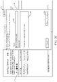
- Figure 3N shows one example of a pop-up display 258 that allows user 150 to specify actions for a hold policy.
- Display 258 illustratively includes a time-based hold mechanism 260 that allows user 150 to specify a time that content is to be held.
- Enablement mechanism 262 allows user 150 to specify when the hold policy is to take effect.
- Figure 3O shows one example of user interface display 250 where the user has actuated the time-based hold mechanism 260. It can be seen that policy action component 192 then generates another display 264 that allows user 150 to identify a certain period of time to hold the contents that are analyzed using the compliance policy.
- Figure 3P illustrates that the user has provided inputs indicating how long to hold the content (6 months) and when to enable the policy (immediately). Referring again to the flow diagram of Figure 3 , receiving user inputs defining policy actions is indicated by block 270.
- Table 2 shows one example of a policy configuration object schema that represents a policy.
- Table 3 shows a markup language representation of the schema. It can be seen in Table 3 that an XML schema expresses a hierarchical relationship of logical conditions. A top level node in the schema shown in Table 3 is referred to as the rule. It expresses a hierarchy of logical nodes of "and” and "or” as well as “not” operators. Each condition inside the node can be a specific point for policy evaluation. Table 3 also shows the schema for representing actions indicated in the rule.
- policy distribution system 154 (shown in Figure 4 ) deploys the unified representation of the policy to the relevant workloads 106-108. This is indicated by block 280 in Figure 3 .
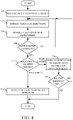
- Figure 4 is a flow diagram illustrating one example of how a policy is deployed, in more detail.
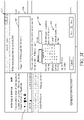
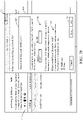
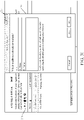
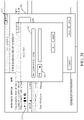
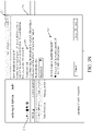
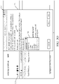
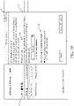
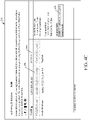
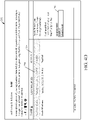
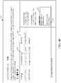
- Figures 4A-4F show examples of user interface displays.
- Figure 4A shows one example of a user interface display 292 that indicates this.
- User interface display 292 shows that user 150 has selected the policy that has already been generated, and is indicated by the highlighted selection 294.
- User 150 then actuates an enable/disable user input mechanism 296. This indicates that the user wishes to change the enable/disable status of the selected policy 294.
- Policy distribution system 154 (shown in Figure 1 ) then generates another user interface display that illustratively allows user 150 to confirm that he or she wishes to enable the highlighted policy 294.
- Figure 4B is an example of a user interface display indicating this. It can be seen that user interface display 292 is similar to that shown in Figure 4A , except that the confirmation dialog 298 is now displayed. It has a user input mechanism 300 that allows user 150 to confirm that the selected policy 294 is to be enabled.
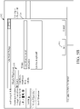
- Policy distribution system 154 then begins enabling or deploying the selected policy 294 to the desired workloads 106-108. In doing so, it illustratively generates a user interface display indicating, with a status indicator, that the policy deployment is in progress. This is indicated by block 302 in the flow diagram of Figure 4 , and Figure 4C shows one example of a user interface display that indicates this. Figure 4C is similar to the user interface display shown in Figure 4A . However, Figure 4C now shows that the status column 304 and the enable/disable mechanism 296 indicate that the selected policy 294 is currently being deployed.
- a policy can be deployed either with errors or without errors. For example, it may be that a policy is successfully deployed to a certain set of mailboxes, where the workload is an electronic mail system, but it was unsuccessfully bound to another set of mailboxes. In this case, the policy is deployed, but with errors. Determining whether the policy has been completely deployed and determining whether it has been deployed with or without errors is indicated by blocks 308 and 310 in the flow diagram of Figure 4 . If it is deployed successfully (without errors), then policy distribution system 154 generates a user interface display that indicates this. Displaying the status as being enabled or deployed without errors is indicated by block 312 in the flow diagram of Figure 4 .
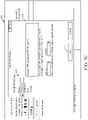
- Figure 4E shows an example of a user interface display that is generated if the policy is deployed with errors. Again, it can be seen that the user interface display shown in Figure 4E is similar to that shown in Figure 4D . However, the status 304 of the selected policy 294 now indicates that the policy is enabled with errors. Further, the enable/disable mechanism 296 also indicates that errors occurred. Mechanism 296 includes a details user input mechanism 314 that allows user 150 to drill down to see additional details of the errors. Displaying the indication of errors with the detail view functionality is indicated by block 316 in the flow diagram of Figure 4E .
- Figure 4F is another example of a user interface display that is similar to that shown in Figure 4E .
- Figure 4F shows that user 150 has actuated the details user input mechanism 314 and a details display 318 is generated. Display 318 describes the errors that occurred. It also includes a redeploy user input mechanism 320. Therefore, user 150 can make modifications to fix the listed errors and actuate user input mechanism 320 to redeploy the policy, if desired.
- Receiving a redeploy input is indicated by block 322 in the flow diagram of Figure 4 . If that occurs, processing reverts back to block 302 where the policy distribution system 154 again attempts to deploy the policy.
- a compliance policy can be disabled or deleted as well.
- policy CRUD system 152 generates suitable user interface displays allowing user 150 to disable or delete the policy.
- policy distribution system 154 generates user interface displays similar to those shown in Figure 4A-4F , except that the user inputs will be to disable the policy rather than enable it. In one example, it may take some time to completely disable a policy from workloads 106-108. In that case, the status indicators will indicate that the policy is being disabled, but that it may take a certain amount of time to disable them. All of these examples are contemplated herein.
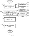
- Policy CRUD system 152 first receives a user input indicating that user 150 wishes to edit an already-existing compliance policy. This is indicated by block 324 in Figure 5 .
- Figure 5A shows one example of a user interface display indicating this. It can be seen that Figure 5A is similar to Figure 4A , and user 150 has selected compliance policy 294. However, Figure 5A shows that user 150 is now actuating an edit user input mechanism 326. This indicates that the user wishes to edit the selected compliance policy. Selecting a policy is indicated by block 328 in the flow diagram of Figure 5 , and actuating the edit mechanism 326 is indicated by block 330. User 150 can provide inputs to indicate that the user wishes to edit a compliance policy in other ways as well, and this is indicated by block 332.
- Figure 5D shows an example of a user interface display where the user has actuated the mailboxes portion of the compliance policy. Therefore, policy CRUD system 152 generates user input mechanisms that allow the user to edit the mailbox bindings for the compliance policy. Similar user input mechanisms as shown if the user selects the site bindings for editing, or the actions portion of the compliance policy for editing.
- user 150 provides edit inputs editing the compliance policy, as desired. Receiving the edits is indicated by block 352 in the flow diagram of Figure 5 . The user then provides a redeploy input (such as actuating save mechanism 350, and actuating a redeploy user input mechanism) in order to redeploy the edits. They are then deployed as described above with respect to Figure 4 . Redeploying the edits to the workloads is indicated by block 354 in Figure 5 .
- a redeploy input such as actuating save mechanism 350, and actuating a redeploy user input mechanism
- Policy distribution system 154 first receives a policy (or a change to a policy) for distribution to one or more workloads 106-108. In one example, it is received from policy CRUD system 152. Receiving the compliance policy or change (e.g., the updates) for distribution is indicated by block 360 in Figure 6 .
- Policy distribution system 154 then saves the update to the central compliance policy store 104. This is indicated by block 362.
- Policy distribution system 154 then identifies the relevant workloads 106-108 where the update is to be applied. In doing so, it can illustratively examine the bindings for the policy to see where the compliance policy is bound, and thus the various workloads where it will need to be applied. Identifying these relevant workloads is indicated by block 364.
- policy distribution system 154 sends the unified representation of the update to the requesting workload. It is illustratively sent to the policy synchronization manager 130-132 for the requesting workload 106-108. This is indicated by block 370 in Figure 6 .
- the synchronization manager then synchronizes the update to the requesting workload and sends back a status indicator 168-170 (in Figure 1 ) to policy status processing system 156, indicating that the policy is being applied, has been applied successfully, has been applied with errors, etc.
- Receiving the status indicator from the requesting workload is indicated by block 372.
- Policy status processing system 156 then updates the distribution status for the compliance policy update. This is indicated by block 374. Examples of how this status is displayed were described with respect to Figures 4C 4F .
- the policy synchronization manager 130-132 of the relevant workload 106-108 keeps track of the various changes it has made so that it can ask for additional changes (that have been notified) as it can make them.
- This approach obtains the advantages of both a push architecture and a pull architecture, while avoiding their disadvantages.
- the advantage of a push architecture is that data is only pushed when a change has been made. This leads to efficiency.
- the disadvantage is that the pusher must maintain connections for all the end points it needs to push. In a large scalable service, this can be problematic as there are too many end points to push and the code to do so becomes relatively complex.
- the advantage of a pull architecture is that the puller only needs to maintain one connection with the source so the code is relatively simple.
- Policy synchronization manager 130 can illustratively include notification receiver 376, in-memory notification queue 378, dispatcher component 380, one or more synchronizer components 382-384, policy CRUD manager 386, tenant information provider 388, and status generator and publisher component 390. It can include other items 392 as well.
- Figure 7 shows that, in one example, policy synchronization manager 130 is also coupled to a persistent storage queue 394. All of the components of policy synchronization manager 130 can share the same interface across all workloads 106-108.
- Notification receiver 376 listens for policy update notifications 165 from policy distribution system 154. It then places them in persistent queue 394 so that they are not lost in case policy synchronization manager 130 crashes or its operation is disrupted for some reason. It also places them in in-memory queue 378. They can be placed in queue 378 in a variety of different orders. For instance, if they are urgent, they can be placed at the top of the queue. Otherwise, they can be placed in the queue on a first-come, first-served basis. Dispatcher component 380 drains the notifications 165 from queue 378.
- Each notification 165 is viewed as a work item that is to be sent to a synchronizer component 382.
- dispatcher component 380 can batch the notifications into batches 394-396 and send them, in batches, to different synchronizer components 382-384.
- Synchronizer components 382-384 call the policy CRUD manager 386 (which can be the same as policy CRUD system 152 shown in Figure 1 , but with a subset of the functionality enabled) to perform the updates represented by the given notification being operated on. In doing so, it can generate pull requests 398 that it sends to policy distribution system 154 to pull the actual compliance policy updates that need to be synchronized.
- Tenant information provider 388 can also make calls on tenant store 110 in order to store relevant tenant information, such as the status of the policy updates, the current version of the policy, diagnostic data (such as how many times a given synchronizer component has attempted to synchronize a policy), etc.
- Status generator and publisher component 390 generates the status indicators indicating the status of application of the given compliance policy update and places it in persistent queue 394 and in-memory queue 378.
- Dispatcher component 300 dispatches the status 170 to a synchronizer component 382 which sends it back to policy status processing system 156, where it can be displayed to the user, as discussed above.
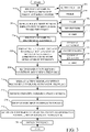
- FIG 8 is a flow diagram illustrating one embodiment of the operation of policy synchronization manager 130 in more detail.
- Notification receiver 376 first receives a notification 165 that a compliance policy update has been generated and is to be synchronized to the workload 106 that contains policy synchronization manager 130.
- the notification can also be referred to as a synchronization request (or sync request).
- Receiving the notification is indicated by block 400 in Figure 8 .
- the notification can indicate that a new compliance policy 402 is to be synchronized to the workload or that a change or update to an existing compliance policy is to be synchronized.
- the notification can also indicate a regular synchronization request 406, or an urgent synchronization request 408.
- a regular request may be provided, for instance, when user 150 simply makes a change to the compliance policy and commits it to central compliance policy store 104. This will cause policy distribution system 154 to send a regular notification to the relevant workload.
- An urgent sync request may be generated, for instance, when the policy synchronization manager 130 has not completed synchronizing a compliance policy, after a normal service interval. In that case, user 150 or policy distribution system 154 may generate an urgent request.
- the notifications can be generated and received in other ways as well, and this is indicated by block 410.
- Notification receiver 376 then places the notification in persistent queue 394 and in in-memory queue 378. It can store the notification in other ways 412 as well. Placing the request in a queue is indicated by block 414. Again, if the notification is a normal notification, notification receiver 376 may simply place the notification in queue 378 and 394 at the end of the queue. However, if it is an urgent notification, then it may be placed at the head of the queue.
- Dispatcher component 380 then spawns one or more synchronizer components 382-384 (if they are needed) and de-queues the notifications 165 from queue 378 and sends them to the spawned synchronizer components. This is indicated by block 416 in the flow diagram of Figure 8 . Again, they can be batched as indicated by block 418. The batches can be sent to synchronizer component 382-384 either in parallel as indicated by block 420 or in serial as indicated by block 422. The notifications can be sent to synchronizer components 382-384 in other ways as well and this is indicated by block 424.
- the synchronizer components 382-384 then call the policy distribution system 154 to pull all updates corresponding to a notification currently being processed. This is indicated by block 426 in Figure 8 . In response, the unified representations of the updates corresponding to the notifications being processed are received.
- the synchronizer component 382-384 then call the policy CRUD manager 386 to perform the updates and to write the updates to the workload policy store 114. This is indicated by block 428.
- Synchronizer components 382-384 then notify the dispatcher component 380 and the status generator and publisher component 390 that the change has been committed. This is indicated by block 430 in Figure 8 .
- the synchronizer components 382-384 can indicate that the update has been committed completely as indicated by block 432 or with errors as indicated by block 434, or in other ways as indicated by block 436.
- Status generator and publisher 390 places the status in queues 394 and 378 (or this can be done by notification receiver 376) where dispatcher component 380 dispatches it to a synchronizer component 382-384.
- the synchronizer component sends the status to the policy status processing system. This is indicated by block 437 in Figure 8 .
- Figure 9 is a flow diagram illustrating one example of the operation of status generator and publisher component 390 in generating and publishing the status of a compliance policy update.
- status generator and publisher component 390 generates the accurate status of application of the compliance policy to the given workload and reports that back to policy status processing system 156 in the compliance policy authoring and management system 102.
- user 150 who may be an administrator of an enterprise system, for instance
- Component 390 first determines whether all of the cascading tasks for a policy update (including automatic retries) have been completed. For instance, it may be that a synchronizer component 382 automatically retires to commit policy updates where the first attempt has failed. If all of these cascading tasks for performing the policy update have not yet been completed, then this is detected by status generator and publisher component 390 and component 390 publishes the status as in-progress, deploying, or some similar status indicating that the compliance policy update is currently in the process of being synchronized to the given workload. Determining whether the tasks are complete and reporting the status as in-progress are indicated by blocks 440 and 442 in Figure 9 .
- the component 390 determines both an object level status for the policy update and a status for each individual binding entry for the compliance policy update. Determining the object level status is indicated by block 444 in Figure 9 , and determining the individual binding status is indicated by block 446.
- policy status processing system 156 rolls up all of the statuses for the policy update, from all of the workloads 106-108 where it is being applied, and displays these statuses, along with drill down functionality so that user 150 can drill into the details of these status indicators. Rolling up all of the statuses is indicated by block 450 in Figure 9 . Rolling them up across workloads is indicated by block 452. Rolling them up across all tenants is indicated by block 454, rolling them up in other ways is indicated by block 456, and displaying them is indicated by block 458.
- Figure 10 shows that policy evaluation system 134 illustratively receives payload information from the workload 106.
- the payload information is indicated by block 460 in Figure 10 . It also accesses the compliance policies 462 from the workload policy store 114. It then evaluates the policies relative to the workload and can indicate actions to be taken 464, it can output the evaluation results 466, and it can generate other items 468 as well.
- Policy evaluation system 134 includes rule parser component 470, compliance item generator 472, applicable policy identifier 474, action generator component 480, matching component 482, extensibility system 484, and it can include other items 486 as well.
- Compliance item generator 472 calls an interface implemented by the workload to generate a unified representation of the payload item 460, so that it can be analyzed against the compliance policies.
- Applicable policy identifier 474 identities relevant policies and rule parser component 470 parses the unified representation of the relevant policies to identify predicates, conditions and actions.
- Action generator component 480 generates action objects corresponding to the actions. Where the actions are workload-specific actions, component 480 calls an interface on the workload and has the workload create the action object.
- Matching component 482 then matches conditions for each rule against the unified representation of the payload item 460 to see if any rules match. If so, it invokes the corresponding action objects to perform desired actions.
- Figures 11A and 11B show a flow diagram illustrating one example of how policy evaluation system 134 evaluates received payload items 460 to determine whether a compliance policy applies to it and if so, the actions that need to be taken.
- Compliance item generator 472 first receives a payload item 460 from the workload. This is indicated by block 488 in Figure 11 .
- the payload item 460 may be a message 490.
- the payload item 460 may be a document 492.
- the payload item will be another type of payload item 494.
- Compliance item generator 472 then generates a unified compliance item representation of the workload item 460. This is indicated by block 496.
- the items to be evaluated e.g., the messages, documents, etc.
- compliance item generator 472 can call an application programming interface (API) implemented by the workload to extract text from the workload item as indicated by block 498. It can also extract common content that is to be placed in the schema. This is indicated by block 500. Calling the API on the workload in order to obtain this type of information is indicated by block 502. It can generate a compliance item in the common schema in other ways as well, and this is indicated by block 504.
- API application programming interface
- Table 4 shows one example of a compliance item schema that can be used to represent a payload item 460 that is received for evaluation by system 134.
- Table 5 shows one example of a class definition of the item, implementing the common schema.
- TABLE 4 Property Name Type Remark Id string Unique ID. Workload Enum Enum of the unique workloads. It is used for logging as well as any future partition purpose. This is a calculated property based on Context.
- Type string Type of the item Name string Friendly name of the item. For mail message, this is the subject. For documents, this is the full document name with extension.
- applicable policy identifier 474 identifies applicable policies that may be applicable to the compliance item. This is indicated by block 505 in Figure 11 .
- the relevant rules or policies can be identified along with the compliance item, itself, as indicated by block 516.
- Component 474 can also evaluate the bindings in the policies being evaluated to determine whether any of its rules apply to this compliance item. This is indicated by block 518. Determining whether the policies apply to this item can be determined in other ways 420 as well.
- Rule parser component 470 parses the compliance policy to identify rules and their predicates and conditions for evaluation.
- the rule parser component 470 reads and parses the unified representation of each rule (e.g., the rule XML) and matches the tag of each condition with an object class factory API to create the runtime object that represents that rule.
- the rule is a workload-specific rule
- the workload implements an API that can be called to create the runtime object that represents that workload-specific rule.
- Action generator 480 creates the objects that represent the actions in the parsed rules. Where they are workload-specific actions, it calls the API on the workload to have the workload create the corresponding objects. Creating the action objects is indicated by block 512 in Figure 11 . Default actions are indicated by block 508, workload-specific actions are indicated by block 510 and other actions are indicated by block 511.
- Extensibility system 482 can be provided in policy evaluation system 134 or spread across a workload.
- system 484 allows extensibility by having system 484 implement workload-specific interfaces.
- a compliance item interface is used to generate the compliance item that represents the payload item (e.g., the document or electronic mail message, etc.) that is to be evaluated.
- a rule parser and condition/action interface is implemented and represents the creation of workload-specific rules.
- a unified compliance policy framework includes an architecture and a set of schemas and APIs.
- the framework enables different services to plug into a single framework to achieve a unified experience in compliance policy management and enforcement.
- a single markup language (e.g., XML) schema and runtime object model expresses compliance policies in a way that can be used by multiple different services or workloads. This significantly increases reliability in the management of such policies.
- a single runtime object model represents payload items that are to be evaluated by the compliance policy evaluation system.
- the single runtime object model represents documents, e-mails, chat conversations, etc., depending upon the workload.
- An extensibility system allows for the addition of different compliance policy scenarios.
- the policy evaluation system 134 can be represented by an application programming interface that can be run across multiple different services or workloads to evaluate policies using the unified schema that represents the policies and the unified schema that represents the objects for evaluation.
- the synchronization system allows policies to be synchronized across various workloads from a central location.
- the synchronization model includes notification and incremental data pulling to obtain the benefits of both types of architectures.
- FIG 12 is a block diagram of architecture 100, shown in Figure 1 , except that its elements are disposed in a cloud computing architecture 501.
- Cloud computing provides computation, software, data access, and storage services that do not require end-user knowledge of the physical location or configuration of the system that delivers the services.
- cloud computing delivers the services over a wide area network, such as the internet, using appropriate protocols.
- cloud computing providers deliver applications over a wide area network and they can be accessed through a web browser or any other computing component.
- Software or components of architecture 100 as well as the corresponding data can be stored on servers at a remote location.
- the computing resources in a cloud computing environment can be consolidated at a remote data center location or they can be dispersed.
- Cloud computing both public and private provides substantially seamless pooling of resources, as well as a reduced need to manage and configure underlying hardware infrastructure.
- a public cloud is managed by a vendor and typically supports multiple consumers using the same infrastructure. Also, a public cloud, as opposed to a private cloud, can free up the end users from managing the hardware.
- a private cloud may be managed by the organization itself and the infrastructure is typically not shared with other organizations. The organization still maintains the hardware to some extent, such as installations and repairs, etc.
- Figure 12 also depicts another embodiment of a cloud architecture.
- Figure 12 shows that it is also contemplated that some elements of architecture 100 can be disposed in cloud 503 while others are not.
- data stores 104, 110, 112, 114 and 116 can be disposed outside of cloud 503, and accessed through cloud 503.
- compliance policy authoring and management system 102 can be outside of cloud 502. Regardless of where they are located, they can be accessed directly by the user devices through a network (either a wide area network or a local area network), they can be hosted at a remote site by a service, or they can be provided as a service through a cloud or accessed by a connection service that resides in the cloud. All of these architectures are contemplated herein.
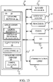
- Figure 13 is a simplified block diagram of one illustrative embodiment of a handheld or mobile computing device that can be used as a user's or client's hand held device 16, in which the present system (or parts of it) can be deployed.
- Figures 14-15 are examples of handheld or mobile devices.
- Examples of communications link 13 include an infrared port, a serial/USB port, a cable network port such as an Ethernet port, and a wireless network port allowing communication though one or more communication protocols including General Packet Radio Service (GPRS), LTE, HSPA, HSPA+ and other 3G and 4G radio protocols, 1Xrtt, and Short Message Service, which are wireless services used to provide cellular access to a network, as well as 802.11 and 802.11b (Wi-Fi) protocols, and Bluetooth protocol, which provide local wireless connections to networks.
- GPRS General Packet Radio Service
- LTE Long Term Evolution
- HSPA High Speed Packet Access
- HSPA+ High Speed Packet Access Plus
- 1Xrtt 3G and 4G radio protocols
- 1Xrtt 1Xrtt
- Short Message Service Short Message Service
- I/O components 23 are provided to facilitate input and output operations.
- I/O components 23 for various embodiments of the device 16 can include input components such as buttons, touch sensors, multi-touch sensors, optical or video sensors, voice sensors, touch screens, proximity sensors, microphones, tilt sensors, and gravity switches and output components such as a display device, a speaker, and or a printer port.
- Other I/O components 23 can be used as well.
- Clock 25 illustratively comprises a real time clock component that outputs a time and date. It can also, illustratively, provide timing functions for processor 17.
- Location system 27 illustratively includes a component that outputs a current geographical location of device 16. This can include, for instance, a global positioning system (GPS) receiver, a LORAN system, a dead reckoning system, a cellular triangulation system, or other positioning system. It can also include, for example, mapping software or navigation software that generates desired maps, navigation routes and other geographic functions.
- GPS global positioning system
- Memory 21 stores operating system 29, network settings 31, applications 33, application configuration settings 35, data store 37, communication drivers 39, and communication configuration settings 41.
- Memory 21 can include all types of tangible volatile and non-volatile computer-readable memory devices. It can also include computer storage media (described below).
- Memory 21 stores computer readable instructions that, when executed by processor 17, cause the processor to perform computer-implemented steps or functions according to the instructions.
- Application 154 or the items in data store 156 for example, can reside in memory 21.
- device 16 can have a client system 24 which can run various applications or embody architecture 100.
- Processor 17 can be activated by other components to facilitate their functionality as well.
- Examples of the network settings 31 include things such as proxy information, Internet connection information, and mappings.
- Application configuration settings 35 include settings that tailor the application for a specific enterprise or user.
- Communication configuration settings 41 provide parameters for communicating with other computers and include items such as GPRS parameters, SMS parameters, connection user names and passwords.
- Applications 33 can be applications that have previously been stored on the device 16 or applications that are installed during use, although these can be part of operating system 29, or hosted external to device 16, as well.
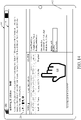
- Figure 14 shows one embodiment in which device 16 is a tablet computer 600.
- computer 600 is shown with the user interface display (from Figure 3A ) displayed on the display screen 602.
- Screen 602 can be a touch screen (so touch gestures from a user's finger 604 can be used to interact with the application) or a pen-enabled interface that receives inputs from a pen or stylus. It can also use an on-screen virtual keyboard. Of course, it might also be attached to a keyboard or other user input device through a suitable attachment mechanism, such as a wireless link or USB port, for instance.
- Computer 600 can also illustratively receive voice inputs as well.
- the mobile device can also be a personal digital assistant (PDA) or a multimedia player or a tablet computing device, etc. (hereinafter referred to as PDA).
- PDA personal digital assistant
- the PDA includes an inductive screen that senses the position of a stylus (or other pointers, such as a user's finger) when the stylus is positioned over the screen. This allows the user to select, highlight, and move items on the screen as well as draw and write.
- the PDA also includes a number of user input keys or buttons which allow the user to scroll through menu options or other display options which are displayed on the display, and allow the user to change applications or select user input functions, without contacting the display.
- the PDA can include an internal antenna and an infrared transmitter/receiver that allow for wireless communication with other computers as well as connection ports that allow for hardware connections to other computing devices.
- Such hardware connections are typically made through a cradle that connects to the other computer through a serial or USB port. As such, these connections are non-network connections.
- Figure 15 shows that the device can be a smart phone 71.
- Smart phone 71 has a touch sensitive display 73 that displays icons or tiles or other user input mechanisms 75. Mechanisms 75 can be used by a user to run applications, make calls, perform data transfer operations, etc.
- smart phone 71 is built on a mobile operating system and offers more advanced computing capability and connectivity than a feature phone.
- Figure 16 is one embodiment of a computing environment in which architecture 100, or parts of it, (for example) can be deployed.
- an exemplary system for implementing some embodiments includes a general-purpose computing device in the form of a computer 810.
- Components of computer 810 may include, but are not limited to, a processing unit 820 (which can comprise various processors from the previous description), a system memory 830, and a system bus 821 that couples various system components including the system memory to the processing unit 820.
- the system bus 821 may be any of several types of bus structures including a memory bus or memory controller, a peripheral bus, and a local bus using any of a variety of bus architectures.
- such architectures include Industry Standard Architecture (ISA) bus, Micro Channel Architecture (MCA) bus, Enhanced ISA (EISA) bus, Video Electronics Standards Association (VESA) local bus, and Peripheral Component Interconnect (PCI) bus also known as Mezzanine bus.
- ISA Industry Standard Architecture
- MCA Micro Channel Architecture
- EISA Enhanced ISA
- VESA Video Electronics Standards Association
- PCI Peripheral Component Interconnect
- Computer 810 typically includes a variety of computer readable media.
- Computer readable media can be any available media that can be accessed by computer 810 and includes both volatile and nonvolatile media, removable and non-removable media.
- Computer readable media may comprise computer storage media and communication media.
- Computer storage media is different from, and does not include, a modulated data signal or carrier wave. It includes hardware storage media including both volatile and nonvolatile, removable and non-removable media implemented in any method or technology for storage of information such as computer readable instructions, data structures, program modules or other data.
- Computer storage media includes, but is not limited to, RAM, ROM, EEPROM, flash memory or other memory technology, CD-ROM, digital versatile disks (DVD) or other optical disk storage, magnetic cassettes, magnetic tape, magnetic disk storage or other magnetic storage devices, or any other medium which can be used to store the desired information and which can be accessed by computer 810.
- Communication media typically embodies computer readable instructions, data structures, program modules or other data in a transport mechanism and includes any information delivery media.
- modulated data signal means a signal that has one or more of its characteristics set or changed in such a manner as to encode information in the signal.
- communication media includes wired media such as a wired network or direct-wired connection, and wireless media such as acoustic, RF, infrared and other wireless media. Combinations of any of the above should also be included within the scope of computer readable media.
- the system memory 830 includes computer storage media in the form of volatile and/or nonvolatile memory such as read only memory (ROM) 831 and random access memory (RAM) 832.
- ROM read only memory
- RAM random access memory
- BIOS basic input/output system 833
- RAM 832 typically contains data and/or program modules that are immediately accessible to and/or presently being operated on by processing unit 820.
- Figure 16 illustrates operating system 834, application programs 835, other program modules 836, and program data 837.
- the computer 810 may also include other removable/non-removable volatile/nonvolatile computer storage media.
- Figure 16 illustrates a hard disk drive 841 that reads from or writes to non-removable, nonvolatile and an optical disk drive 855 that reads from or writes to a removable, nonvolatile optical disk 856 such as a CD ROM or other optical media.
- Other removable/non-removable, volatile/nonvolatile computer storage media that can be used in the exemplary operating environment include, but are not limited to, magnetic tape cassettes, flash memory cards, digital versatile disks, digital video tape, solid state RAM, solid state ROM, and the like.
- the hard disk drive 841 is typically connected to the system bus 821 through a non-removable memory interface such as interface 840, and optical disk drive 855 are typically connected to the system bus 821 by a removable memory interface, such as interface 850.
- the functionality described herein can be performed, at least in part, by one or more hardware logic components.
- illustrative types of hardware logic components include Field-programmable Gate Arrays (FPGAs), Program-specific Integrated Circuits (ASICs), Program-specific Standard Products (ASSPs), System-on-a-chip systems (SOCs), Complex Programmable Logic Devices (CPLDs), etc.
- hard disk drive 841 is illustrated as storing operating system 844, application programs 845, other program modules 846, and program data 847. Note that these components can either be the same as or different from operating system 834, application programs 835, other program modules 836, and program data 837. Operating system 844, application programs 845, other program modules 846, and program data 847 are given different numbers here to illustrate that, at a minimum, they are different copies.
- Example 1 is a computer-implemented method, comprising:
- Example 2 is the computer-implemented method of any or all previous examples wherein displaying a status display element comprises: displaying the status display element indicative of whether the compliance policy update is currently being deployed or whether deployment has completed.
- Example 3 is the computer-implemented method of any or all previous examples wherein automatically receiving comprises: receiving an error indication indicative of errors in application of the compliance policy update to the workload.
- Example 4 is the computer-implemented method of any or all previous examples wherein displaying a status display element comprises: displaying the status display element indicative of whether the compliance policy update is deployed successfully or whether it is deployed with errors based on the error indication.
- Example 6 is the computer-implemented method of any or all previous examples wherein receiving an error indication comprises: receiving a binding level error indication indicative of portions of the workload that the compliance policy update was unsuccessfully deployed to.
- Example 7 is the computer-implemented method of any or all previous examples wherein displaying the status display element indicative of the compliance policy update being deployed with errors comprises: displaying the binding level error indication along with a drill user input mechanism actuatable to display an error detail display showing details corresponding to the binding level error indicator.
- Example 8 is the computer-implemented method of any or all previous examples wherein the workload comprises a multi-tenant workload and wherein displaying the status display element comprises: displaying a status display element indicative of a deployment status of the compliance policy update across all tenants in the multi-tenant workload.
- Example 9 is the computer-implemented method of any or all previous examples wherein sending comprises: sending the compliance policy update to a plurality of different workloads for deployment to the plurality of different workloads.
- Example 11 is a computer-implemented method, comprising:
- Example 12 is the computer-implemented method of any or all previous examples wherein identifying a status of deployment comprises: identifying whether the deployment is in progress or completed
- Example 13 is the computer-implemented method of any or all previous examples wherein identifying a status comprises: if the deployment is completed, identifying whether the compliance policy update is deployed successfully or with errors.
- Example 14 is the computer-implemented method of any or all previous examples wherein identifying a status comprises: if the deployment is completed with errors, identifying the errors.
- Example 15 is the computer-implemented method of any or all previous examples wherein automatically deploying the compliance policy update comprises: deploying the compliance policy update to different portions of the workload identified by bindings in the compliance policy update.
- Example 16 is the computer-implemented method of any or all previous examples wherein identifying a status comprises: identifying a binding level status indicative of a status of the deployment to each portion of the workload.
- Example 17 is a compliance policy system, comprising:
- Example 18 is the compliance policy system of any or all previous examples wherein the status processing system generates the policy status display element to indicate a status of deployment of the compliance policy update to each of the plurality of different workloads.
- Example 20 is the compliance policy system of any or all previous examples wherein the workloads are multi-tenant workloads and wherein the status processing system generates the policy status display element to identify a deployment status across tenants in the multi-tenant workloads.
Landscapes
- Engineering & Computer Science (AREA)
- Business, Economics & Management (AREA)
- Strategic Management (AREA)
- Human Resources & Organizations (AREA)
- Entrepreneurship & Innovation (AREA)
- Theoretical Computer Science (AREA)
- Economics (AREA)
- Physics & Mathematics (AREA)
- General Physics & Mathematics (AREA)
- Quality & Reliability (AREA)
- Marketing (AREA)
- General Business, Economics & Management (AREA)
- Tourism & Hospitality (AREA)
- Operations Research (AREA)
- General Engineering & Computer Science (AREA)
- Educational Administration (AREA)
- Development Economics (AREA)
- Data Mining & Analysis (AREA)
- Game Theory and Decision Science (AREA)
- Computer Security & Cryptography (AREA)
- Computer Networks & Wireless Communication (AREA)
- Signal Processing (AREA)
- Computing Systems (AREA)
- Computer Hardware Design (AREA)
- Human Computer Interaction (AREA)
- General Health & Medical Sciences (AREA)
- Artificial Intelligence (AREA)
- Computational Linguistics (AREA)
- Health & Medical Sciences (AREA)
- Audiology, Speech & Language Pathology (AREA)
- Information Transfer Between Computers (AREA)
- Stored Programmes (AREA)
- Information Retrieval, Db Structures And Fs Structures Therefor (AREA)
- Computer And Data Communications (AREA)
- User Interface Of Digital Computer (AREA)
- Mobile Radio Communication Systems (AREA)
Abstract
Description
- Computer systems are currently in wide use. Some computer systems have compliance policies associated with them. The compliance policies often apply to the data that is generated or used in the computer system.
- By way of example, an electronic mail system may have certain compliance policies. For instance, it may be that a compliance policy exists by which any electronic mail message that contains a customer's social security number must be encrypted prior to being sent. A document management system may also have associated compliance policies. For instance, for legal reasons, it may be that certain business documents must be maintained or stored for a certain number of years, before they are deleted. Of course, these and a wide variety of other computer systems can have many additional or different compliance policies associated with them as well.
- Currently, compliance policies are managed separately in each different type of computer system. For instance, an electronic mail computer system has its own compliance policies which are managed within that system. A document management system has its own compliance policies which are managed within that system. Electronic meeting computer systems often have compliance policies which are managed within that system as well. The tasks to configure the compliance policies in each of the systems can be cumbersome and difficult.
- The discussion above is merely provided for general background information and is not intended to be used as an aid in determining the scope of the claimed subject matter.
- A set of compliance policy updates are received. The compliance policy updates are sent to workloads for application. A status of the application of the compliance policies to the workloads is received from the workloads and output.
- This Summary is provided to introduce a selection of concepts in a simplified form that are further described below in the Detailed Description. This Summary is not intended to identify key features or essential features of the claimed subject matter, nor is it intended to be used as an aid in determining the scope of the claimed subject matter. The claimed subject matter is not limited to implementations that solve any or all disadvantages noted in the background.
-
-
Figure 1 is a block diagram of one example of a compliance policy architecture. -
Figure 1A is a block diagram showing one example of a compliance policy. -
Figure 2 is a block diagram showing one example of a policy create, read, update and deleted (CRUD) system. -
Figure 3 is a flow diagram illustrating one example of the operation of the architecture shown inFigure 1 is creating a compliance policy. -
Figures 3A-3Q show examples of user interface displays. -
Figure 4 is a flow diagram illustrating one example of the operation of the architecture shown inFigure 1 in deploying a compliance policy update. -
Figures 4A-4F show various examples of user interface displays. -
Figure 5 is a flow diagram illustrating one example of the operation of the architecture shown inFigure 1 in receiving and deploying an edit to a compliance policy. -
Figures 5A-5D show various examples of user interface displays. -
Figure 6 is a flow diagram illustrating one example of the operation of the architecture shown inFigure 1 in distributing compliance policies, in more detail. -
Figure 7 is a block diagram showing one example of a policy synchronization manager in more detail. -
Figure 8 is a flow diagram illustrating one example of the operation of the policy synchronization manager shown inFigure 7 . -
Figure 9 is a flow diagram illustrating one example of how policy application status is reported. -
Figure 10 is a block diagram showing one example of a policy evaluation system in more detail. -
Figures 11A and11B (collectivelyFigure 11 ) show a flow diagram illustrating one example of how policies are evaluated against content (or payload items). -
Figure 12 is a block diagram showing one example of the architecture illustrated inFigure 1 , deployed in a cloud computing architecture. -
Figures 13-15 show various examples of mobile devices. -
Figure 16 is a block diagram of one example of a computing environment. -
Figure 1 is a block diagram of one example of acompliance policy architecture 100.Architecture 100 can be used to author or update compliance policies and distribute them to systems where they are applied. - In the example shown in
Figure 1 ,architecture 100 includes compliance policy authoring andmanagement system 102, centralcompliance policy store 104, a plurality of different workloads 106-108, each of which have a tenant data store 110-112 and a policy store 114-116. - In the example shown in
Figure 1 , each workload 106-108 can be a single tenant or multi-tenant workload that comprises a computer system that generates a set of user interface displays 118-120, with user input mechanisms 122-124, for interaction by users 126-128. Users 126-128 interact with the user input mechanisms 122-124 in order to control and manipulate workloads 106-108, respectively. By way of example,workload 106 may be an electronic mail computer system whileworkload 108 may be a document management computer system, an electronic meeting computer system, etc. Each workload illustratively has a policy synchronization manager 130-132, a policy evaluation system 134-136, one or more processors or servers 138-140, and they can include other items 142-144 as well. - The example shown in
Figure 1 also illustrates that compliance policy authoring andmanagement system 102 can, itself, generate user interface displays 146 with user input mechanisms 148 for interaction byuser 150.User 150 can illustratively interact with user input mechanisms 148 in order to generate or update compliancepolicies using system 102, and to have those policies synchronized to workloads 106-108, where they are applied. Thus, compliance policy authoring andmanagement system 102 illustratively includespolicy CRUD system 152,policy distribution system 154, policystatus processing system 156,user interface component 158, one or more processors orservers 160 and it can includeother items 162 as well. Before describing the overall operation of architecture of 100 in more detail, a brief overview will first be provided. -
User 150first accesses system 102 in order to generate a compliance policy update. This can be to add one or more new compliance policies or rules, to delete them or to modify them. In any case,policy CRUD system 152 provides functionality that allowsuser 150 to do that. The policies are represented by a unified schema that is the same across all different workloads.User 150 then invokespolicy distribution system 154 that distributes thecompliance policy updates 166 to the various workloads 106-108 where they are to be applied.Policy distribution system 154 sendsnotifications 165 to workloads 106-108 thatpolicy updates 166 are available for them. Policy synchronization managers 130-132 then pull thecompliance updates 166 so that they can be applied in workloads 106-108, respectively. Thesynchronization managers compliance policy updates 166 to their respective workload policy stores 114-116. Synchronization managers 130-132 communicate statuses 168-170, respectively, back to policystatus processing system 156 where the status of the application of thecompliance policy updates 166 is communicated touser 150. The compliance policies can then be used during runtime by a unified policy evaluation system that is the same in each workload. The workload coverts items (like emails and documents) to be analyzed under the compliance policies into a unified representation that is the same across the workloads. The unified policy evaluation system evaluates the items and can call the workload to create instances of action objects that will perform workload-specific actions when a compliance policy is triggered. -
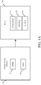
Figure 1A shows one example of acompliance policy 172.Compliance policy 172 is illustratively a collection ofrules 174. Eachrule 174 illustratively includes one or more predicates that are a collection ofconditions 176 that indicate when the rule is to be applied. They also illustratively include a set ofbindings 178 that indicate what particular items within workloads 106-108 the rules are to be applied to, and they may indicateactions 180 indicating the type of actions that are to be taken, when a compliance policy rule is triggered by an item of content in one of the workloads 106-108. - By way of example, a predicate for a
rule 174 may combine a set of conditions using a logical AND operation. Theconditions 176 ofrule 174 may be that the body of an electronic mail message contains the word "foo" and the word "bar". The binding 178 may be a list of electronic mail accounts or mailboxes that are to be evaluated for thisrule 174, and theaction 180 may be that the electronic mail message containing the word "foo" and the word "bar" is encrypted. -
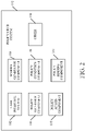
Figure 2 is a block diagram illustrating one example of apolicy CRUD system 152 in more detail. In the example shown inFigure 2 ,policy CRUD system 152 includes auser interface system 182,schema generator component 184,policy identifier component 186,policy condition component 188,policy binding component 190,policy action component 192, and it can includeother items 194 as well. -
User interface system 182 can generate user interface displays 146 that allowuser 150 to generate compliance policy updates.Schema generator component 184 illustratively generates a schema, that is unified across all workloads 106-108, to represent the policy update.Policy identifier component 186 allowsuser 150 to identify an update as a new policy or a modification to a policy.Policy condition component 186 allowsuser 150 to identify the conditions associated with the new policy or the update.Policy binding component 190 allowsuser 150 to bind the new policy or updates to various items in the workloads 106-108, andpolicy action component 192 allowsuser 150 to specify actions associated with a new policy, or to modify the actions associated with an existing policy. -
Figure 3 is a flow diagram illustrating one example of the operation ofpolicy CRUD system 152 in allowinguser 150 to specify a new compliance policy. Specifying a new compliance policy is, of course, included as acompliance policy update 166 shown inFigure 1 . Therefore, it is to be provided to the relevant workloads 106-108 through their policy synchronization managers 130-132.Figures 3A-3Q show examples of user interface displays that can be generated in allowinguser 150 to create a new compliance policy. - Compliance policy authoring and
management system 102 first receives a user input indicating that the user wishes to access the compliance policy authoring andmanagement system 102 in order to generate a new compliance policy. This is indicated byblock 200 inFigure 3 . By way of example,user 150 can provide anauthentication input 202, orother inputs 204. - In response,
policy CRUD system 152 displays a set of user interface displays that allowuser 150 to generate the new compliance policy. First, for example, it can display one or more policy identifying user interface displays with mechanisms that allowuser 150 to identify the new policy. This is indicated byblock 206. The policy identifying user interface displays can allowuser 150 to input apolicy name 208, apolicy description 210, and other identifyinginformation 212. -
Figure 3A shows one example of auser interface display 214 that indicates this. It can be seen inFigure 3A that two sets of compliance policies are shown. One for "North Wind Case" and one for "South Wind Case". The user has selected the "North Wind Case" set of compliance policies and is actuating auser input mechanism 216 that allowsuser 150 to add to the compliance policies. - It will be noted that the present description proceeds with respect to
user 150 adding a hold policy. This is a policy that determines how long and under what conditions certain types of data are to be stored. For instance, certain kinds of data may be stored, for legal reasons, for a certain number of years. Other data may be stored, by default, for a certain number of years, but it may be otherwise deleted by the user at any time. Still other data may be automatically deleted after a certain period of time, and other information may be stored indefinitely. Of course, this is but one type of compliance policy and a wide variety of other compliance policies can be implemented. The one described is described for the sake of example only. -
Figure 3B shows another example ofuser interface display 214. It can be seen inFigure 3B thatpolicy identifier component 186 has generated a pop-updisplay 218 that allows the user to enter policy identifying information.Display 218 has aname text box 220 and adescription text box 222.User 150 can illustratively enter a name intext box 220 and a description of the compliance policy intext box 222. InFigure 3C , it can be seen that the user has entered the name "North Wind Financial" to identify the compliance policy. The user has also entered a description as "the purpose of this hold is to A, B and C". Receiving user inputs identifying the policy is indicated byblock 224 in the flow diagram ofFigure 3 . Once the policy identifying inputs are complete, the user can advance, such as by actuating the "next"button 226. -
Policy condition component 188 andpolicy binding component 190 then illustratively generate user interface displays that allowuser 150 to define predicates and conditions for the policy being created and to provide scope inputs that indicate what the policy being authored is to bind or apply to. This is indicated byblock 228 inFigure 3 . Table 1 below is a table showing some examples of predicates. Table 1 below can be read as a prefix plus a suffix. The prefix is the parent node and the suffix is the child node (e.g., CreationDateEqual, CreationDateGreaterThan, etc.)TABLE 1 CreationDate • Equal • GreaterThen • GreaterThenOrEqual • LessThen • LessThenOrEqual • NotEqual • Exists Creator • Is • Exists • Matches • ContainsWords LastModified • Equal • GreaterThen • GreaterThenOrEqual • LessThen • LessThenOrEqual • NotEqual • Exists LastModifier • Is • Exists • Matches • ContainsWords Name • Is • Exists • Matches • ContainsWords • MatchesPatterns Extension - file name extension • Is • Exists • Matches • ContainsWords • MatchesPatterns Body • ContainsClassifications • Is • Exists • Matches • ContainsWords • SizeOver Attachment • ContrainsClassifications • Is • Exists • Matches • ContainsWords • SizeOver • IsExecutable • IsBinaryTypeOf Or True False And Not - By way of example, the UI displays may allow
user 150 to providecontent keywords 230. It can allowuser 150 to identify that a condition is that these keywords are present in the content of the item being analyzed. It may also allowuser 150 to provide content dates 232. Therefore, only content that is dated within the dates provided will be analyzed under this policy. It may be that it allowsuser 150 to provide a content location (such as certain URLs that contain content, certain e-mail addresses or inboxes, etc.), that the compliance policy is to be bound to. This indicates thelocation 234 of content where the compliance policy will apply. The conditions and binding inputs can includeother items 236 as well. -
Figure 3D shows an example of auser interface display 214, where pop-updisplay 238 has been generated. It can be seen that pop-updisplay 238 allows the user to enter keywords into atext field 240. In that case, these keywords will be a condition for the compliance policy. That is, content being analyzed must contain the keywords in order for the policy to apply. -
Figure 3D also shows that atimeframe mechanism 242 is displayed, which allowsuser 150 to specify a timeframe for content, as a condition for the application of this policy. It also includes alocation mechanism 244 that allowsuser 150 to specify a location of the content to be analyzed for this policy (such as certain mailboxes, sites, etc.). -
Figure 3E shows another user interface display that indicates that the user has entered the keywords "August" and "financials near repo∗" in thekeyword text box 240. Thus, for the current compliance policy to be applied to any content, the content must include the keywords "August" and the term "financials" in close proximity to the term "repo∗".Figure 3E also shows that the user has actuated the timeframeuser input mechanism 242. Thus,policy condition component 188 illustratively generates a date picker user interface display such as that shown inFigure 3E , that allows the user to pick a start and/or end date of the content. Thus, if content is dated within the range of dates specified by the start and/or end dates, the condition will be satisfied. -
Figure 3F shows another embodiment ofuser interface display 214. InFigure 3F , it can be seen that the user has now also indicated that he or she also wishes to specify certain mailboxes and sites for application of the currently authored compliance policy. The user can then actuatenext button 226. In that case,Figure 3G shows thatpolicy binding component 190 can generate anotherdisplay 246. It allowsuser 150 to bind the policy to content that is located in certain locations. In the example shown inFigure 3G , pop-updisplay 246 allowsuser 150 to choose certain mailboxes to which the compliance policy is to be applied. By actuating theadd mechanism 248,user 150 can illustratively see a set of e-mail addresses to select from. One example of this is indicated inFigure 3H . - It can be seen in
Figure 3H that the system has now displayed a set ofe-mail boxes 250 that can be selected byuser 150.User 150 can select from the list shown in pop-updisplay 250 and actuateadd button 252 to add those e-mail boxes to the list of e-mail boxes where the currently-authored compliance policy will apply.Figure 3I shows another example of pop-updisplay 246 which now contains the electronic mailboxes that were chosen by the user inFigure 3H . - In one example,
user 150 can also include distribution lists, along with or instead of individual e-mail boxes.Figure 3J shows an example of pop-updisplay 246 where the user has selected not only the two e-mail addresses shown inFigure 3I , but also the "Human Resources" distribution list. -
Figure 3K shows thatpolicy binding component 190 can also generate a similar user interface display 148 that allows theuser 150 to select other locations (such as sites) for application of the policy.Figure 3L shows that the user can add sites by typing them intoselection box 250 and actuating addmechanism 252, or by adding them in other ways.Figure 3M shows pop-updisplay 248 after the user has selected a site where the new compliance policy is to be applied. - Referring again to the flow diagram of
Figure 3 , receiving the user inputs that define conditions and scoping of the compliance policy is indicated byblock 254. - Policy action component 192 (shown in
Figure 2 ) then generates user interface displays that allowuser 150 to specify actions that are to be taken when the compliance policy is triggered. This is indicated byblock 256. The particular actions may be dependent on the particular scenario for which the compliance policy is generated. By way of example, if the compliance policy is a hold policy, then the actions may indicate how long the content is to be held, whether and under what conditions they can be deleted, etc. However, if the compliance policy is a security policy, it may indicate what types of content are to be encrypted prior to being sent with a messaging system. A wide variety of other actions can be defined as well. -
Figure 3N shows one example of a pop-updisplay 258 that allowsuser 150 to specify actions for a hold policy.Display 258 illustratively includes a time-basedhold mechanism 260 that allowsuser 150 to specify a time that content is to be held.Enablement mechanism 262 allowsuser 150 to specify when the hold policy is to take effect. -
Figure 3O shows one example ofuser interface display 250 where the user has actuated the time-basedhold mechanism 260. It can be seen thatpolicy action component 192 then generates anotherdisplay 264 that allowsuser 150 to identify a certain period of time to hold the contents that are analyzed using the compliance policy.Figure 3P illustrates that the user has provided inputs indicating how long to hold the content (6 months) and when to enable the policy (immediately). Referring again to the flow diagram ofFigure 3 , receiving user inputs defining policy actions is indicated byblock 270. - It will be noted that, in one example, at any time, the user can review and confirm the policy details that have just been input.
Figure 3Q shows one example of apolicy detail display 272. It can be seen thatpolicy detail display 272 includes the various details of the policy that has just been configured. - Once the policy is adequately defined by the user, the user can provide an input to deploy the policy. This is indicated by
block 276 in the flow diagram ofFigure 3 . When that occurs,schema generator component 184 generates a representation of the newly authored compliance policy according to a unified schema that is unified across all of the various workloads to which compliance policies are to be applied. This is indicated byblock 278 inFigure 3 . - Table 2 shows one example of a policy configuration object schema that represents a policy. Table 3 shows a markup language representation of the schema. It can be seen in Table 3 that an XML schema expresses a hierarchical relationship of logical conditions. A top level node in the schema shown in Table 3 is referred to as the rule. It expresses a hierarchy of logical nodes of "and" and "or" as well as "not" operators. Each condition inside the node can be a specific point for policy evaluation. Table 3 also shows the schema for representing actions indicated in the rule. This can easily be extended by including new tags in the schema to represent new conditions, and new nodes in the action schema to represent workload-specific actions (like encryption, etc.)
TABLE 2 ATTRIBUTE TYPE DETAILS SEARCHABLE DISPLAY NAME string Friendly, display name of the policy/rule (required). Unique within a policy Yes TYPE Int Policy or Rule type (required) Yes SUB-TYPE Int Sub type such as Hold, Dlp, and Rention Yes IDENTITY string Unique, immutable identifier for the policy/rule within the tenant scope (required) Yes PARENT string ID of the parent container. Only required for rule type Yes WORKLOAD Int (flags) Flag enum to indicate which workload this policy/rule applies to such as Ex, SP etc. (required) No MODE Int Policy/rule mode: Audit, Enforce etc. (Required) Yes ENABLED bool If a policy is enabled or disabled (Required) Yes PRIORITY Int Priority (only set and required for rule type) No BINDINGS ICollection<string> A collection of binding Ids Yes ASSOCIATIONS ICollection<string> A collection of association Ids Yes RAWCONTENT string Raw XML of the policy/rule data (required for rule type and optional for policy type) No TABLE 3
<rule name="Policy1" mode="Audit" enabled="true" activationDate="01/01/2013"
 expiryDate="01/01/2014">
 <version requiredMinVersion="15.0.3.1 ">
  <!-- tags are used to connect individual rules to a Policy-->
  <tags>
   <tag name="bf418349-a5dd-4ae5-b595-9af96bc48aa6" type="CP" />
  </tags>
  <condition>
   <and>
     <!-- Predicate elements, see next condition for an example -->
    <PredicateName property="PropertyName">
     <Values>
      <Value>Value - specific for a condition type</Value>
     </Values>
     <keyValues>
        <keyValue key="specific for condition type" value="10" />
        <keyValue key="maxCount" value="-1" />
     </keyValues>
    </conditionName>
    <!-Example: ExceptIfFromMemberOf predicate -->
    <not>
     <or>
      <isMemberOf property="Message.From">
        <value>testdl@acme.com</value>
        <value>testdl2@acme.com </value>
      </isMemberOf>
     </or>
    </not>
   </and>
  </condition>
  <!-Action schema, see next action for an example -->
  <action name="ActionName">
   <!- arguments are positional parameters -->
   <argument value="action-specific value" />
  </action>
  <!-- -SenderNotify RejectUnlessExplicitOverride action -->
  <action name="SenderNotify">
   <argument value="RejectUnlessExplicitOverride" />
   <argument value="550" />
   <argument value="5.7.1" />
   <argument value="Unable to deliver your message. You can override this policy by
   adding the word 'override' to the subject line." />
  </action>
 </version>
</rule> | Property Name | Type | Remark |
| Id | string | Unique ID. |
| Workload | Enum | Enum of the unique workloads. It is used for logging as well as any future partition purpose. This is a calculated property based on Context. |
| Type | string | Type of the item. |
| Name | string | Friendly name of the item. For mail message, this is the subject. For documents, this is the full document name with extension. |
| Created | DateTime | Creation time |
| Creator | string | UPN or Common Name of the creator |
| LastModified | DateTime | Last modified time |
| LastModifier | string | UPN or Common Name of the last modifier |
| Expiry | DateTime | Expiry date of the itemExpiry date of the item |
| Classifications Scanned | IList<Guid> | List of classifications item was scanned for. May contain a special Guid that indicates AllA vailableClassifications |
| ClassificationsDiscovered | IList<Guid> | List of classifications of the item after content analysis in the forms of GUID |
| BodyStream | Stream | Message or document body binary stream. Exposed as a GetBodyStream method to express caller stream ownership |
| BodyText | Stream | Message or document body text, if available. Exposed as a GetBodyText method |
| Attachments | IList<PolicyItem> | List of attachments |
| ShouldAudit | Boolean | Indicates whether actions applied on this item should add audit trail |
 /// <summary>
 /// Represents an item (a unit of work) passed into the policy engine
 /// </summary>
 public class PolicyItem
 {
  virtual public string Id { get; private set }
  virtual public string Type { get; private set; }
  virtual public string Name { get; private set; }
  virtual public DateTime CreationDate { get; private set; }
  virtual public string Creator { get; private set; }
  virtual public DateTime LastModified { get; private set; }
    virtual public string LastModifier { get; private set; }
    virtual public DateTime Expiry { get; private set; }
  static const Guid AllClassifications = new Guid("1EF9DD8A-D749-476C-906C-
  FD66E1CF44FD");
  virtual public IList<Guid> ClassificationsScanned { get; }
  virtual public IList<Guid> ClassificationsDiscovered { get; }
  virtual public Stream GetBodyStream();
  virtual public Stream GetBodyTextStream();
  virtual public string Type { get; }
  virtual public IList<PolicyItem> Attachments { get; }
virtual public bool ShouldAudit { get; private set; } - sending a compliance policy update from a compliance policy authoring system to a workload for deployment to the workload;
- automatically receiving a compliance policy status indicator from the workload indicative of a status of deployment of the compliance policy update to the workload; and
- displaying a status display element indicative of the status indicated by the compliance policy status indicator.
displaying the status display element indicative of whether the compliance policy update is currently being deployed or whether deployment has completed.
receiving an error indication indicative of errors in application of the compliance policy update to the workload.
displaying the status display element indicative of whether the compliance policy update is deployed successfully or whether it is deployed with errors based on the error indication.
sending the compliance policy update with bindings indicative of which portions of the workload that the compliance policy update applies to.
receiving a binding level error indication indicative of portions of the workload that the compliance policy update was unsuccessfully deployed to.
displaying the binding level error indication along with a drill user input mechanism actuatable to display an error detail display showing details corresponding to the binding level error indicator.
displaying a status display element indicative of a deployment status of the compliance policy update across all tenants in the multi-tenant workload.
sending the compliance policy update to a plurality of different workloads for deployment to the plurality of different workloads.
displaying a status display element indicative of a deployment status of the compliance policy update across all of the plurality of different workloads.
- receiving a compliance policy update at a workload;
- automatically deploying the compliance policy update to the workload;
- automatically identifying a status of deployment of the compliance policy update to the workload; and
- sending a status indicator indicative of the status of deployment to a compliance policy authoring and management system.
identifying whether the deployment is in progress or completed
if the deployment is completed, identifying whether the compliance policy update is deployed successfully or with errors.
if the deployment is completed with errors, identifying the errors.
deploying the compliance policy update to different portions of the workload identified by bindings in the compliance policy update.
identifying a binding level status indicative of a status of the deployment to each portion of the workload.
- a policy distribution system that distributes a compliance policy update to a plurality of different workloads;
- a policy status processing system that receives a status indicator from each of the workloads indicative of a deployment status of the compliance policy update to the workload and generates a policy status display element based on the status indicators;
- a user interface component that displays the policy status display element; and
- a computer processor that is a functional part of the system and is activated by the policy distribution system, the policy status processing system and the user interface component to facilitate distributing, generating and displaying.
Claims (13)
- A computer system for facilitating policy compliance, the system comprising:a policy distribution system that distributes a compliance policy update to a plurality of different workloads;a policy status processing system that receives a status indicator from each of the workloads indicative of a deployment status of the compliance policy update to the workload and generates a policy status display element based on the status indicators;a user interface component that displays the policy status display element; anda computer processor that is a functional part of the system and is activated by the policy distribution system, the policy status processing system and the user interface component to facilitate distributing, generating and displaying.
- The computer system of claim 1 wherein the policy status processing system generates the policy status display element to indicate a status of deployment of the compliance policy update to each of the plurality of different workloads.
- The computer system of claim 2 wherein the compliance policy update is applied to different portions of each of the workloads based on bindings corresponding to the compliance policy update and wherein the status processing system generates the policy status display element to identify portions of the workloads in which the deployment encountered an error.
- The computer system of claim 3 wherein the workloads are multi-tenant workloads and wherein the policy status processing system generates the policy status display element to identify a deployment status across tenants in the multi-tenant workloads.
- A computer-implemented method, comprising:sending a compliance policy update from a compliance policy authoring system to a workload for deployment to the workload;automatically receiving a compliance policy status indicator from the workload indicative of a status of deployment of the compliance policy update to the workload;displaying a status display element indicative of whether the compliance policy update is currently being deployed or whether deployment has completed; andwherein automatically receiving includes receiving an error indication indicative of errors in application of the compliance policy update to the workload, and wherein displaying a status display element comprises displaying the status display element indicative of whether the compliance policy update is deployed successfully or whether it is deployed with errors based on the error indication.
- The computer-implemented method of claim 5 wherein sending comprises:
sending the compliance policy update with bindings indicative of which portions of the workload that the compliance policy update applies to. - The computer-implemented method of claim 6 wherein receiving an error indication comprises:
receiving a binding level error indication indicative of portions of the workload that the compliance policy update was unsuccessfully deployed to, and wherein displaying the status display element indicative of the compliance policy update being deployed with errors comprises displaying the binding level error indication along with a drill user input mechanism actuatable to display an error detail display showing details corresponding to the binding level error indicator. - The computer-implemented method of claim 5 wherein the workload comprises a multi-tenant workload and wherein displaying the status display element comprises:
displaying a status display element indicative of a deployment status of the compliance policy update across all tenants in the multi-tenant workload. - The computer-implemented method of claim 8 wherein sending comprises:
sending the compliance policy update to a plurality of different workloads for deployment to the plurality of different workloads, and wherein displaying the status display element comprises displaying a status display element indicative of a deployment status of the compliance policy update across all of the plurality of different workloads. - A computer-implemented method, comprising:receiving a compliance policy update at a workload;automatically deploying the compliance policy update to the workload;automatically identifying a status of deployment of the compliance policy update to the workload; andsending a status indicator indicative of the status of deployment to a compliance policy authoring and management system.
- The computer-implemented method of claim 10 wherein identifying a status of deployment comprises:
identifying whether the deployment is in progress or completed; and if the deployment is completed, identifying whether the compliance policy update is deployed successfully or with errors. - The computer-implemented method of claim 11 wherein identifying a status comprises:
if the deployment is completed with errors, identifying the errors, and further comprising re-deploying the compliance policy update to the workload when the identified errors are remedied. - The computer-implemented method of claim 10 wherein automatically deploying the compliance policy update comprises:
deploying the compliance policy update to different portions of the workload identified by bindings in the compliance policy update, and wherein identifying a status comprises identifying a binding level status indicative of a status of the deployment to each portion of the workload.
Applications Claiming Priority (4)
| Application Number | Priority Date | Filing Date | Title |
|---|---|---|---|
| US201461947195P | 2014-03-03 | 2014-03-03 | |
| US14/327,886 US9432405B2 (en) | 2014-03-03 | 2014-07-10 | Communicating status regarding application of compliance policy updates |
| PCT/US2015/018219 WO2015134341A1 (en) | 2014-03-03 | 2015-03-02 | Communicating status regarding application of compliance policy updates |
| EP15711931.4A EP3114622B1 (en) | 2014-03-03 | 2015-03-02 | Communicating status regarding application of compliance policy updates |
Related Parent Applications (2)
| Application Number | Title | Priority Date | Filing Date |
|---|---|---|---|
| EP15711931.4A Division EP3114622B1 (en) | 2014-03-03 | 2015-03-02 | Communicating status regarding application of compliance policy updates |
| EP15711931.4A Division-Into EP3114622B1 (en) | 2014-03-03 | 2015-03-02 | Communicating status regarding application of compliance policy updates |
Publications (1)
| Publication Number | Publication Date |
|---|---|
| EP3982312A1 true EP3982312A1 (en) | 2022-04-13 |
Family
ID=54007303
Family Applications (2)
| Application Number | Title | Priority Date | Filing Date |
|---|---|---|---|
| EP15711931.4A Active EP3114622B1 (en) | 2014-03-03 | 2015-03-02 | Communicating status regarding application of compliance policy updates |
| EP21210532.4A Pending EP3982312A1 (en) | 2014-03-03 | 2015-03-02 | Communicating status regarding application of compliance policy updates |
Family Applications Before (1)
| Application Number | Title | Priority Date | Filing Date |
|---|---|---|---|
| EP15711931.4A Active EP3114622B1 (en) | 2014-03-03 | 2015-03-02 | Communicating status regarding application of compliance policy updates |
Country Status (4)
| Country | Link |
|---|---|
| US (6) | US9432405B2 (en) |
| EP (2) | EP3114622B1 (en) |
| CN (2) | CN106068521B (en) |
| WO (1) | WO2015134341A1 (en) |
Families Citing this family (33)
| Publication number | Priority date | Publication date | Assignee | Title |
|---|---|---|---|---|
| US9432405B2 (en) | 2014-03-03 | 2016-08-30 | Microsoft Technology Licensing, Llc | Communicating status regarding application of compliance policy updates |
| CN106464540B (en) * | 2014-06-26 | 2019-11-19 | 华为技术有限公司 | System and method for virtual network function policy management |
| US9781098B2 (en) | 2014-09-24 | 2017-10-03 | Oracle International Corporation | Generic server framework for device authentication and management and a generic framework for endpoint command dispatch |
| CN107735789B (en) * | 2016-06-07 | 2020-12-01 | 华为技术有限公司 | Method and terminal for improving information security |
| US10180956B2 (en) * | 2016-07-08 | 2019-01-15 | Veeva Systems Inc. | Configurable commit in a content management system |
| US10686673B1 (en) * | 2016-07-29 | 2020-06-16 | Juniper Networks, Inc. | Methods and apparatus for centralized operational management of heterogenous network devices through software-based node unification |
| US10594721B1 (en) | 2016-11-09 | 2020-03-17 | StratoKey Pty Ltd. | Proxy computer system to provide selective decryption |
| US10798064B1 (en) | 2016-11-09 | 2020-10-06 | StratoKey Pty Ltd. | Proxy computer system to provide encryption as a service |
| US10848494B2 (en) * | 2017-08-14 | 2020-11-24 | Microsoft Technology Licensing, Llc | Compliance boundaries for multi-tenant cloud environment |
| US10545755B2 (en) * | 2017-09-07 | 2020-01-28 | Servicenow, Inc. | Identifying customization changes between instances |
| US20200028879A1 (en) | 2018-07-17 | 2020-01-23 | Microsoft Technology Licensing, Llc | Queryless device configuration determination-based techniques for mobile device management |
| US11184223B2 (en) | 2018-07-31 | 2021-11-23 | Microsoft Technology Licensing, Llc | Implementation of compliance settings by a mobile device for compliance with a configuration scenario |
| CN109327434B (en) * | 2018-09-04 | 2021-07-30 | 郑州云海信息技术有限公司 | A system and method for hybrid management security policy |
| US12135682B1 (en) | 2018-09-14 | 2024-11-05 | StratoKey Pty Ltd. | Archival system and service for use with third-party network services |
| US10936751B1 (en) | 2018-12-14 | 2021-03-02 | StratoKey Pty Ltd. | Selective anonymization of data maintained by third-party network services |
| US12189815B1 (en) | 2018-12-14 | 2025-01-07 | Stratokey Pty Ltd | Selective replacement of data maintained by third-party network services |
| US11146592B2 (en) * | 2019-01-16 | 2021-10-12 | Vmware, Inc. | Enforcing universal security policies across data centers |
| US11050627B2 (en) * | 2019-06-19 | 2021-06-29 | Arista Networks, Inc. | Method and network device for enabling in-place policy updates |
| US10789103B1 (en) * | 2019-09-06 | 2020-09-29 | Capital One Services, Llc | Executing computing modules using multi-coring |
| US11741409B1 (en) | 2019-12-26 | 2023-08-29 | StratoKey Pty Ltd. | Compliance management system |
| US11416874B1 (en) * | 2019-12-26 | 2022-08-16 | StratoKey Pty Ltd. | Compliance management system |
| US11228571B2 (en) * | 2020-02-05 | 2022-01-18 | International Business Machines Corporation | Policy-based topic-level encryption for message queues |
| US11797685B2 (en) * | 2020-09-18 | 2023-10-24 | Check Point Software Technologies Ltd. | System and method for performing automated security reviews |
| US11662994B1 (en) * | 2020-10-20 | 2023-05-30 | Metactix Llc | System and method for updating an application for a population of computers |
| US12058023B2 (en) * | 2021-06-28 | 2024-08-06 | Arista Networks, Inc. | Staging in-place updates of packet processing rules of network devices to eliminate packet leaks |
| CN115705554A (en) * | 2021-08-06 | 2023-02-17 | 北京字跳网络技术有限公司 | Data processing method, electronic device and storage medium |
| US11388248B1 (en) | 2021-08-18 | 2022-07-12 | StratoKey Pty Ltd. | Dynamic domain discovery and proxy configuration |
| US12081438B2 (en) * | 2021-10-11 | 2024-09-03 | Hewlett Packard Enterprise Development Lp | Automatic policy engine selection |
| US20230177435A1 (en) * | 2021-12-03 | 2023-06-08 | International Business Machines Corporation | Modularized governance of continuous compliance |
| US12149564B2 (en) | 2022-07-29 | 2024-11-19 | Cisco Technology, Inc. | Compliant node identification |
| US12225052B2 (en) | 2022-07-31 | 2025-02-11 | Cisco Technology, Inc. | Compliant data transfers |
| CN117668862A (en) * | 2022-08-22 | 2024-03-08 | 华为云计算技术有限公司 | Authentication method, device, system and storage medium |
| US12284218B2 (en) * | 2022-11-29 | 2025-04-22 | Juniper Networks, Inc. | Efficient updating of device-level security configuration based on changes to security intent policy model |
Citations (3)
| Publication number | Priority date | Publication date | Assignee | Title |
|---|---|---|---|---|
| WO2003040944A1 (en) * | 2001-11-09 | 2003-05-15 | Bigfix, Inc. | Formalizing, diffusing, and enforcing policy advisories and monitoring policy compliance in the management of networks |
| US20030154404A1 (en) * | 2001-08-14 | 2003-08-14 | Smartpipes, Incorporated | Policy engine for modular generation of policy for a flat, per-device database |
| US20070124797A1 (en) * | 2003-07-25 | 2007-05-31 | Rajiv Gupta | Policy based service management |
Family Cites Families (61)
| Publication number | Priority date | Publication date | Assignee | Title |
|---|---|---|---|---|
| EP1143664A3 (en) | 1999-06-10 | 2003-11-26 | Alcatel Internetworking, Inc. | Object model for network policy management |
| US6684244B1 (en) | 2000-01-07 | 2004-01-27 | Hewlett-Packard Development Company, Lp. | Aggregated policy deployment and status propagation in network management systems |
| US6779120B1 (en) | 2000-01-07 | 2004-08-17 | Securify, Inc. | Declarative language for specifying a security policy |
| US7475107B2 (en) * | 2002-07-08 | 2009-01-06 | Electronic Evidence Discovery, Inc. | System and method for managing distributed computer processes |
| US20040193703A1 (en) | 2003-01-10 | 2004-09-30 | Guy Loewy | System and method for conformance and governance in a service oriented architecture |
| US7624422B2 (en) | 2003-02-14 | 2009-11-24 | Preventsys, Inc. | System and method for security information normalization |
| US7069553B2 (en) * | 2003-03-03 | 2006-06-27 | Computer Associates Think, Inc. | Universal deployment tool |
| US10110632B2 (en) | 2003-03-31 | 2018-10-23 | Intel Corporation | Methods and systems for managing security policies |
| US20040268229A1 (en) | 2003-06-27 | 2004-12-30 | Microsoft Corporation | Markup language editing with an electronic form |
| US20070180490A1 (en) | 2004-05-20 | 2007-08-02 | Renzi Silvio J | System and method for policy management |
| US8799242B2 (en) | 2004-10-08 | 2014-08-05 | Truecontext Corporation | Distributed scalable policy based content management |
| US7797739B2 (en) * | 2004-12-14 | 2010-09-14 | International Business Machines Corporation | Automated verification of correctness of aspects of an information technology system |
| US8028334B2 (en) * | 2004-12-14 | 2011-09-27 | International Business Machines Corporation | Automated generation of configuration elements of an information technology system |
| US20110167470A1 (en) | 2005-02-28 | 2011-07-07 | Trust Digital, Llc | Mobile data security system and methods |
| US9053460B2 (en) | 2006-06-12 | 2015-06-09 | International Business Machines Corporation | Rule management using a configuration database |
| US8352998B1 (en) | 2006-08-17 | 2013-01-08 | Juniper Networks, Inc. | Policy evaluation in controlled environment |
| US7809955B2 (en) | 2006-10-17 | 2010-10-05 | Blue Ridge Networks, Inc. | Trustable communities for a computer system |
| US8104080B2 (en) | 2007-01-26 | 2012-01-24 | Microsoft Corporation | Universal schema for representing management policy |
| US20080184200A1 (en) * | 2007-01-26 | 2008-07-31 | Microsoft Corporation | Software configuration policies' validation, distribution, and enactment |
| US20080184277A1 (en) * | 2007-01-26 | 2008-07-31 | Microsoft Corporation | Systems management policy validation, distribution and enactment |
| US8838755B2 (en) | 2007-03-23 | 2014-09-16 | Microsoft Corporation | Unified service management |
| US8209738B2 (en) | 2007-05-31 | 2012-06-26 | The Board Of Trustees Of The University Of Illinois | Analysis of distributed policy rule-sets for compliance with global policy |
| US8499331B1 (en) | 2007-06-27 | 2013-07-30 | Emc Corporation | Policy based network compliance |
| US8819164B2 (en) | 2007-08-31 | 2014-08-26 | Microsoft Corporation | Versioning management |
| US8621550B1 (en) | 2007-09-28 | 2013-12-31 | Emc Corporation | Information technology resource compliance templates |
| US7885943B1 (en) | 2007-10-02 | 2011-02-08 | Emc Corporation | IT compliance rules |
| US8396838B2 (en) | 2007-10-17 | 2013-03-12 | Commvault Systems, Inc. | Legal compliance, electronic discovery and electronic document handling of online and offline copies of data |
| CN101441560B (en) | 2007-11-23 | 2012-09-26 | 国际商业机器公司 | Method and apparatus for executing service-oriented architecture policy based on context model |
| US20090241165A1 (en) | 2008-03-19 | 2009-09-24 | Verizon Business Network Service, Inc. | Compliance policy management systems and methods |
| US9489647B2 (en) | 2008-06-19 | 2016-11-08 | Csc Agility Platform, Inc. | System and method for a cloud computing abstraction with self-service portal for publishing resources |
| US8370796B2 (en) * | 2008-08-26 | 2013-02-05 | International Business Machines Corporation | Development tooling enablement for audit event generation |
| US8380684B2 (en) * | 2008-09-30 | 2013-02-19 | Microsoft Corporation | Data-tier application component fabric management |
| US8627328B2 (en) * | 2008-11-14 | 2014-01-07 | Oracle International Corporation | Operation control for deploying and managing software service in a virtual environment |
| US8560941B2 (en) | 2009-04-08 | 2013-10-15 | Microsoft Corporation | Schema based user interface mechanisms |
| US8972553B2 (en) * | 2009-08-10 | 2015-03-03 | Qualcomm Incorporated | Method and apparatus for handling policy and charging control rule or quality of service rule modification failures |
| US10169723B2 (en) | 2009-11-11 | 2019-01-01 | International Business Machines Corporation | Distributed policy distribution for compliance functionality |
| US20110126197A1 (en) | 2009-11-25 | 2011-05-26 | Novell, Inc. | System and method for controlling cloud and virtualized data centers in an intelligent workload management system |
| US8127350B2 (en) | 2010-06-30 | 2012-02-28 | Juniper Networks, Inc. | Multi-service VPN network client for mobile device |
| US20120011517A1 (en) | 2010-07-08 | 2012-01-12 | Virginia Smith | Generation of operational policies for monitoring applications |
| US8539545B2 (en) | 2010-07-22 | 2013-09-17 | Juniper Networks, Inc. | Domain-based security policies |
| US9336396B2 (en) | 2010-10-25 | 2016-05-10 | Radware, Ltd. | Method and system for generating an enforceable security policy based on application sitemap |
| US9032013B2 (en) | 2010-10-29 | 2015-05-12 | Microsoft Technology Licensing, Llc | Unified policy over heterogenous device types |
| US9094291B1 (en) | 2010-12-14 | 2015-07-28 | Symantec Corporation | Partial risk score calculation for a data object |
| US9208332B2 (en) * | 2010-12-24 | 2015-12-08 | Microsoft Technology Licensing, Llc | Scoped resource authorization policies |
| US8914843B2 (en) * | 2011-09-30 | 2014-12-16 | Oracle International Corporation | Conflict resolution when identical policies are attached to a single policy subject |
| US8578111B2 (en) | 2011-10-11 | 2013-11-05 | Hewlett-Packard Development Company, L.P. | Backup optimization policy table for controlling buffered/un-buffered input/output |
| US20140032733A1 (en) * | 2011-10-11 | 2014-01-30 | Citrix Systems, Inc. | Policy-Based Application Management |
| US8869235B2 (en) * | 2011-10-11 | 2014-10-21 | Citrix Systems, Inc. | Secure mobile browser for protecting enterprise data |
| US8966085B2 (en) | 2012-01-04 | 2015-02-24 | International Business Machines Corporation | Policy-based scaling of computing resources in a networked computing environment |
| US9379937B2 (en) * | 2012-02-23 | 2016-06-28 | International Business Machines Corporation | Policy-based resource management with target-driven remediation on server |
| EP2712450A4 (en) | 2012-03-30 | 2015-09-16 | Commvault Systems Inc | Informaton management of mobile device data |
| US9086929B2 (en) * | 2012-04-06 | 2015-07-21 | International Business Machines Corporation | Dynamic allocation of a workload across a plurality of clouds |
| US9626526B2 (en) | 2012-04-30 | 2017-04-18 | Ca, Inc. | Trusted public infrastructure grid cloud |
| US9438547B2 (en) * | 2012-07-10 | 2016-09-06 | Microsoft Technology Licensing, Llc | Uniform policy for security and information protection |
| US9317696B2 (en) | 2012-07-10 | 2016-04-19 | Microsoft Technology Licensing, Llc | Data detection and protection policies for e-mail |
| US20140222521A1 (en) * | 2013-02-07 | 2014-08-07 | Ibms, Llc | Intelligent management and compliance verification in distributed work flow environments |
| US20140222522A1 (en) * | 2013-02-07 | 2014-08-07 | Ibms, Llc | Intelligent management and compliance verification in distributed work flow environments |
| US9807116B2 (en) | 2013-05-03 | 2017-10-31 | Vmware, Inc. | Methods and apparatus to identify priorities of compliance assessment results of a virtual computing environment |
| JP6351225B2 (en) | 2013-09-02 | 2018-07-04 | キヤノン株式会社 | Image processing apparatus, information processing system, control method therefor, and program for information processing apparatus and image processing apparatus |
| US9195833B2 (en) | 2013-11-19 | 2015-11-24 | Veracode, Inc. | System and method for implementing application policies among development environments |
| US9432405B2 (en) | 2014-03-03 | 2016-08-30 | Microsoft Technology Licensing, Llc | Communicating status regarding application of compliance policy updates |
-
2014
- 2014-07-10 US US14/327,886 patent/US9432405B2/en active Active
- 2014-07-21 US US14/336,815 patent/US9444847B2/en active Active
- 2014-07-22 US US14/337,793 patent/US20150249683A1/en not_active Abandoned
- 2014-07-24 US US14/340,126 patent/US9380074B2/en active Active
-
2015
- 2015-03-02 EP EP15711931.4A patent/EP3114622B1/en active Active
- 2015-03-02 WO PCT/US2015/018219 patent/WO2015134341A1/en not_active Ceased
- 2015-03-02 EP EP21210532.4A patent/EP3982312A1/en active Pending
- 2015-03-02 CN CN201580011962.XA patent/CN106068521B/en active Active
- 2015-03-02 CN CN201910635508.1A patent/CN110378593B/en active Active
-
2016
- 2016-05-26 US US15/165,711 patent/US9832231B2/en active Active
- 2016-07-20 US US15/215,032 patent/US9674227B2/en active Active
Patent Citations (3)
| Publication number | Priority date | Publication date | Assignee | Title |
|---|---|---|---|---|
| US20030154404A1 (en) * | 2001-08-14 | 2003-08-14 | Smartpipes, Incorporated | Policy engine for modular generation of policy for a flat, per-device database |
| WO2003040944A1 (en) * | 2001-11-09 | 2003-05-15 | Bigfix, Inc. | Formalizing, diffusing, and enforcing policy advisories and monitoring policy compliance in the management of networks |
| US20070124797A1 (en) * | 2003-07-25 | 2007-05-31 | Rajiv Gupta | Policy based service management |
Also Published As
| Publication number | Publication date |
|---|---|
| US20160277449A1 (en) | 2016-09-22 |
| CN110378593B (en) | 2023-07-28 |
| US20150249682A1 (en) | 2015-09-03 |
| US9380074B2 (en) | 2016-06-28 |
| US20160330248A1 (en) | 2016-11-10 |
| US20150249681A1 (en) | 2015-09-03 |
| CN110378593A (en) | 2019-10-25 |
| US9444847B2 (en) | 2016-09-13 |
| US20150249683A1 (en) | 2015-09-03 |
| CN106068521A (en) | 2016-11-02 |
| US20150249684A1 (en) | 2015-09-03 |
| US9674227B2 (en) | 2017-06-06 |
| WO2015134341A1 (en) | 2015-09-11 |
| US9432405B2 (en) | 2016-08-30 |
| EP3114622A1 (en) | 2017-01-11 |
| US9832231B2 (en) | 2017-11-28 |
| CN106068521B (en) | 2019-08-13 |
| EP3114622B1 (en) | 2021-12-29 |
Similar Documents
| Publication | Publication Date | Title |
|---|---|---|
| EP3114622B1 (en) | Communicating status regarding application of compliance policy updates | |
| US10936808B2 (en) | Document linking in an electronic messaging system | |
| US9395890B2 (en) | Automatic discovery of system behavior | |
| US20180124155A1 (en) | Network-based group communication and file sharing system | |
| US11734631B2 (en) | Filtering records on a unified display | |
| US20240037066A1 (en) | File access permission revocation notification | |
| US20160026944A1 (en) | Identifying new display elements in a unified thread | |
| US10547580B2 (en) | Dynamically re-parenting email messages based on updated conversations | |
| WO2022152040A1 (en) | Information processing method and apparatus, and electronic device and storage medium | |
| US20160026953A1 (en) | In-line creation of activities on a unified display | |
| US20160274736A1 (en) | Synchronized multi-window interaction with hierarchical data on thin-client | |
| US20160026945A1 (en) | Taking in-line contextual actions on a unified display | |
| US9798769B2 (en) | Sharing document links from multiple data providers | |
| CN114095466B (en) | Nested collaboration in email | |
| US20160378574A1 (en) | Integration and synchronization using a virtual data provider | |
| US10229159B2 (en) | Data surfacing control framework | |
| WO2015179583A1 (en) | Contextual information monitoring |
Legal Events
| Date | Code | Title | Description |
|---|---|---|---|
| PUAI | Public reference made under article 153(3) epc to a published international application that has entered the european phase |
Free format text: ORIGINAL CODE: 0009012 |
|
| STAA | Information on the status of an ep patent application or granted ep patent |
Free format text: STATUS: THE APPLICATION HAS BEEN PUBLISHED |
|
| AC | Divisional application: reference to earlier application |
Ref document number: 3114622 Country of ref document: EP Kind code of ref document: P |
|
| AK | Designated contracting states |
Kind code of ref document: A1 Designated state(s): AL AT BE BG CH CY CZ DE DK EE ES FI FR GB GR HR HU IE IS IT LI LT LU LV MC MK MT NL NO PL PT RO RS SE SI SK SM TR |
|
| STAA | Information on the status of an ep patent application or granted ep patent |
Free format text: STATUS: REQUEST FOR EXAMINATION WAS MADE |
|
| 17P | Request for examination filed |
Effective date: 20220615 |
|
| RBV | Designated contracting states (corrected) |
Designated state(s): AL AT BE BG CH CY CZ DE DK EE ES FI FR GB GR HR HU IE IS IT LI LT LU LV MC MK MT NL NO PL PT RO RS SE SI SK SM TR |
|
| STAA | Information on the status of an ep patent application or granted ep patent |
Free format text: STATUS: EXAMINATION IS IN PROGRESS |
|
| 17Q | First examination report despatched |
Effective date: 20240125 |
|
| GRAP | Despatch of communication of intention to grant a patent |
Free format text: ORIGINAL CODE: EPIDOSNIGR1 |
|
| STAA | Information on the status of an ep patent application or granted ep patent |
Free format text: STATUS: GRANT OF PATENT IS INTENDED |
|
| INTG | Intention to grant announced |
Effective date: 20260306 |