EP3982297A1 - Methods and systems for training a machine learning method - Google Patents
Methods and systems for training a machine learning method Download PDFInfo
- Publication number
- EP3982297A1 EP3982297A1 EP20201283.7A EP20201283A EP3982297A1 EP 3982297 A1 EP3982297 A1 EP 3982297A1 EP 20201283 A EP20201283 A EP 20201283A EP 3982297 A1 EP3982297 A1 EP 3982297A1
- Authority
- EP
- European Patent Office
- Prior art keywords
- approximations
- implemented method
- sensor
- computer implemented
- training
- Prior art date
- Legal status (The legal status is an assumption and is not a legal conclusion. Google has not performed a legal analysis and makes no representation as to the accuracy of the status listed.)
- Granted
Links
Images

Classifications
-
- G—PHYSICS
- G01—MEASURING; TESTING
- G01S—RADIO DIRECTION-FINDING; RADIO NAVIGATION; DETERMINING DISTANCE OR VELOCITY BY USE OF RADIO WAVES; LOCATING OR PRESENCE-DETECTING BY USE OF THE REFLECTION OR RERADIATION OF RADIO WAVES; ANALOGOUS ARRANGEMENTS USING OTHER WAVES
- G01S13/00—Systems using the reflection or reradiation of radio waves, e.g. radar systems; Analogous systems using reflection or reradiation of waves whose nature or wavelength is irrelevant or unspecified
- G01S13/66—Radar-tracking systems; Analogous systems
- G01S13/72—Radar-tracking systems; Analogous systems for two-dimensional [2D] tracking, e.g. combination of angle and range tracking, track-while-scan radar
- G01S13/723—Radar-tracking systems; Analogous systems for two-dimensional [2D] tracking, e.g. combination of angle and range tracking, track-while-scan radar by using numerical data
-
- G—PHYSICS
- G06—COMPUTING OR CALCULATING; COUNTING
- G06N—COMPUTING ARRANGEMENTS BASED ON SPECIFIC COMPUTATIONAL MODELS
- G06N20/00—Machine learning
-
- G—PHYSICS
- G01—MEASURING; TESTING
- G01S—RADIO DIRECTION-FINDING; RADIO NAVIGATION; DETERMINING DISTANCE OR VELOCITY BY USE OF RADIO WAVES; LOCATING OR PRESENCE-DETECTING BY USE OF THE REFLECTION OR RERADIATION OF RADIO WAVES; ANALOGOUS ARRANGEMENTS USING OTHER WAVES
- G01S13/00—Systems using the reflection or reradiation of radio waves, e.g. radar systems; Analogous systems using reflection or reradiation of waves whose nature or wavelength is irrelevant or unspecified
- G01S13/86—Combinations of radar systems with non-radar systems, e.g. sonar, direction finder
- G01S13/865—Combination of radar systems with lidar systems
-
- G—PHYSICS
- G01—MEASURING; TESTING
- G01S—RADIO DIRECTION-FINDING; RADIO NAVIGATION; DETERMINING DISTANCE OR VELOCITY BY USE OF RADIO WAVES; LOCATING OR PRESENCE-DETECTING BY USE OF THE REFLECTION OR RERADIATION OF RADIO WAVES; ANALOGOUS ARRANGEMENTS USING OTHER WAVES
- G01S7/00—Details of systems according to groups G01S13/00, G01S15/00, G01S17/00
- G01S7/02—Details of systems according to groups G01S13/00, G01S15/00, G01S17/00 of systems according to group G01S13/00
- G01S7/41—Details of systems according to groups G01S13/00, G01S15/00, G01S17/00 of systems according to group G01S13/00 using analysis of echo signal for target characterisation; Target signature; Target cross-section
- G01S7/417—Details of systems according to groups G01S13/00, G01S15/00, G01S17/00 of systems according to group G01S13/00 using analysis of echo signal for target characterisation; Target signature; Target cross-section involving the use of neural networks
-
- G—PHYSICS
- G06—COMPUTING OR CALCULATING; COUNTING
- G06N—COMPUTING ARRANGEMENTS BASED ON SPECIFIC COMPUTATIONAL MODELS
- G06N3/00—Computing arrangements based on biological models
- G06N3/02—Neural networks
- G06N3/04—Architecture, e.g. interconnection topology
- G06N3/0464—Convolutional networks [CNN, ConvNet]
-
- G—PHYSICS
- G06—COMPUTING OR CALCULATING; COUNTING
- G06N—COMPUTING ARRANGEMENTS BASED ON SPECIFIC COMPUTATIONAL MODELS
- G06N3/00—Computing arrangements based on biological models
- G06N3/02—Neural networks
- G06N3/08—Learning methods
-
- G—PHYSICS
- G06—COMPUTING OR CALCULATING; COUNTING
- G06N—COMPUTING ARRANGEMENTS BASED ON SPECIFIC COMPUTATIONAL MODELS
- G06N3/00—Computing arrangements based on biological models
- G06N3/02—Neural networks
- G06N3/08—Learning methods
- G06N3/0895—Weakly supervised learning, e.g. semi-supervised or self-supervised learning
-
- G—PHYSICS
- G06—COMPUTING OR CALCULATING; COUNTING
- G06N—COMPUTING ARRANGEMENTS BASED ON SPECIFIC COMPUTATIONAL MODELS
- G06N3/00—Computing arrangements based on biological models
- G06N3/02—Neural networks
- G06N3/08—Learning methods
- G06N3/09—Supervised learning
-
- G—PHYSICS
- G01—MEASURING; TESTING
- G01S—RADIO DIRECTION-FINDING; RADIO NAVIGATION; DETERMINING DISTANCE OR VELOCITY BY USE OF RADIO WAVES; LOCATING OR PRESENCE-DETECTING BY USE OF THE REFLECTION OR RERADIATION OF RADIO WAVES; ANALOGOUS ARRANGEMENTS USING OTHER WAVES
- G01S17/00—Systems using the reflection or reradiation of electromagnetic waves other than radio waves, e.g. lidar systems
- G01S17/88—Lidar systems specially adapted for specific applications
- G01S17/93—Lidar systems specially adapted for specific applications for anti-collision purposes
- G01S17/931—Lidar systems specially adapted for specific applications for anti-collision purposes of land vehicles
-
- G—PHYSICS
- G01—MEASURING; TESTING
- G01S—RADIO DIRECTION-FINDING; RADIO NAVIGATION; DETERMINING DISTANCE OR VELOCITY BY USE OF RADIO WAVES; LOCATING OR PRESENCE-DETECTING BY USE OF THE REFLECTION OR RERADIATION OF RADIO WAVES; ANALOGOUS ARRANGEMENTS USING OTHER WAVES
- G01S13/00—Systems using the reflection or reradiation of radio waves, e.g. radar systems; Analogous systems using reflection or reradiation of waves whose nature or wavelength is irrelevant or unspecified
- G01S13/88—Radar or analogous systems specially adapted for specific applications
- G01S13/93—Radar or analogous systems specially adapted for specific applications for anti-collision purposes
- G01S13/931—Radar or analogous systems specially adapted for specific applications for anti-collision purposes of land vehicles
- G01S2013/9318—Controlling the steering
-
- G—PHYSICS
- G01—MEASURING; TESTING
- G01S—RADIO DIRECTION-FINDING; RADIO NAVIGATION; DETERMINING DISTANCE OR VELOCITY BY USE OF RADIO WAVES; LOCATING OR PRESENCE-DETECTING BY USE OF THE REFLECTION OR RERADIATION OF RADIO WAVES; ANALOGOUS ARRANGEMENTS USING OTHER WAVES
- G01S13/00—Systems using the reflection or reradiation of radio waves, e.g. radar systems; Analogous systems using reflection or reradiation of waves whose nature or wavelength is irrelevant or unspecified
- G01S13/88—Radar or analogous systems specially adapted for specific applications
- G01S13/93—Radar or analogous systems specially adapted for specific applications for anti-collision purposes
- G01S13/931—Radar or analogous systems specially adapted for specific applications for anti-collision purposes of land vehicles
- G01S2013/93185—Controlling the brakes
-
- G—PHYSICS
- G01—MEASURING; TESTING
- G01S—RADIO DIRECTION-FINDING; RADIO NAVIGATION; DETERMINING DISTANCE OR VELOCITY BY USE OF RADIO WAVES; LOCATING OR PRESENCE-DETECTING BY USE OF THE REFLECTION OR RERADIATION OF RADIO WAVES; ANALOGOUS ARRANGEMENTS USING OTHER WAVES
- G01S13/00—Systems using the reflection or reradiation of radio waves, e.g. radar systems; Analogous systems using reflection or reradiation of waves whose nature or wavelength is irrelevant or unspecified
- G01S13/88—Radar or analogous systems specially adapted for specific applications
- G01S13/93—Radar or analogous systems specially adapted for specific applications for anti-collision purposes
- G01S13/931—Radar or analogous systems specially adapted for specific applications for anti-collision purposes of land vehicles
- G01S2013/9319—Controlling the accelerator
-
- G—PHYSICS
- G01—MEASURING; TESTING
- G01S—RADIO DIRECTION-FINDING; RADIO NAVIGATION; DETERMINING DISTANCE OR VELOCITY BY USE OF RADIO WAVES; LOCATING OR PRESENCE-DETECTING BY USE OF THE REFLECTION OR RERADIATION OF RADIO WAVES; ANALOGOUS ARRANGEMENTS USING OTHER WAVES
- G01S13/00—Systems using the reflection or reradiation of radio waves, e.g. radar systems; Analogous systems using reflection or reradiation of waves whose nature or wavelength is irrelevant or unspecified
- G01S13/88—Radar or analogous systems specially adapted for specific applications
- G01S13/93—Radar or analogous systems specially adapted for specific applications for anti-collision purposes
- G01S13/931—Radar or analogous systems specially adapted for specific applications for anti-collision purposes of land vehicles
- G01S2013/9323—Alternative operation using light waves
-
- G—PHYSICS
- G01—MEASURING; TESTING
- G01S—RADIO DIRECTION-FINDING; RADIO NAVIGATION; DETERMINING DISTANCE OR VELOCITY BY USE OF RADIO WAVES; LOCATING OR PRESENCE-DETECTING BY USE OF THE REFLECTION OR RERADIATION OF RADIO WAVES; ANALOGOUS ARRANGEMENTS USING OTHER WAVES
- G01S7/00—Details of systems according to groups G01S13/00, G01S15/00, G01S17/00
- G01S7/02—Details of systems according to groups G01S13/00, G01S15/00, G01S17/00 of systems according to group G01S13/00
- G01S7/40—Means for monitoring or calibrating
- G01S7/4004—Means for monitoring or calibrating of parts of a radar system
- G01S7/4026—Antenna boresight
Definitions
- the present disclosure provides a computer implemented method, a computer system and a non-transitory computer readable medium according to the independent claims. Embodiments are given in the subclaims, the description and the drawings.
- the present disclosure is directed at a computer implemented method for training a machine learning method, the method comprising the following steps performed (in other words: carried out) by computer hardware components: determining measurement data from a first sensor; determining approximations of ground truths based on a second sensor; training the machine learning method based on the measurement data and the approximations of ground truths; wherein approximations of ground truths of lower approximation quality have a lower effect on the training than approximations of ground truths of higher approximation quality.
- the method may allow handling inter-sensor perception discrepancies for machine learning without human intervention.
- the method may provide automatic labelling of imperfect sensor and non-matched radar and lidar data for a machine learning model.
- approximations of ground truths of lower approximation quality have a lower effect on the training than approximations of ground truths of higher approximation quality by using an optimization criterion for the training, wherein the optimization criterion is based on a mapping.
- the mapping may reflect which regions of ground truth are reliable or not.
- approximations of ground truths of lower approximation quality have a lower effect on the training than approximations of ground truths of higher approximation quality by filtering out approximations of ground truths of lower approximation quality.
- the machine learning method is configured to classify objects.
- the approximations of ground truths are determined based on the second sensor using an automated method (for example without human interaction or with only a limited amount of human interaction, which is faster than classification based on the measurement data of the first sensor would be).
- the present disclosure is directed at a computer system, said computer system comprising a plurality of computer hardware components configured to carry out several or all steps of the computer implemented method described herein.
- the present disclosure is directed at a non-transitory computer readable medium comprising instructions for carrying out several or all steps or aspects of the computer implemented method described herein.
- the computer readable medium may be configured as: an optical medium, such as a compact disc (CD) or a digital versatile disk (DVD); a magnetic medium, such as a hard disk drive (HDD); a solid state drive (SSD); a read only memory (ROM), such as a flash memory; or the like.
- the computer readable medium may be configured as a data storage that is accessible via a data connection, such as an internet connection.
- the computer readable medium may, for example, be an online data repository or a cloud storage.
- the present disclosure is also directed at a computer program for instructing a computer to perform several or all steps or aspects of the computer implemented method described herein.
- methods and system are provided with which a machine learning model may be trained using such imperfect data, and at the same time acceptable results may be reached.
- the discrepancy between labels and the input signal i.e. the measurement data, for example input radar signal
- the mapping from input radar signal to output segmentation mask may be learned.
- the cross entropy between the network prediction f(x) and the target variable y may be minimized.
- the input signal x may be a Cartesian grid representation of an environment perceived by an automotive radar sensor.
- the target variable y may be the grid representation of labels of the same environment created using lidar data.
- the input signal may be the radar energy and the output signal may be labels created using lidar data.
- Using the above measure alone for optimization may force the network to learn some artifacts which may deliver unintended results. This may mean that it may be desired to avoid giving importance to unreliable regions. According to various embodiments, this may be done by first identifying reliable regions of ground truth which can be used for training and then exclude the rest during neural network optimization.
- a first step may be to identify the reliable areas of the ground truth. Let us denote this by the variable r i , where the subscript denotes grid cell i .
- a ground truth grid cell y i ⁇ ⁇ free (0), occupied (1) ,unknown (2) ⁇ That means a grid cell in ground truth can have any of the above three values 0 (indicating the ground truth "free"), 1 (indicating the ground truth "occupied"), or 2 (indicating the ground truth "unknown”).
- N ground truth cells may be considered unreliable, if there is a conflict between lidar and radar sensor measurements.
- T 1 may be T_high, which will be described below.
- T 2 may be T_low, which will be described below.
- Regions where x i > T 1 may provide hints that that radar may indicate that it is occupied but if y i is not 1, then the Lidar sensor data may contradict with it. Then the cell may be marked as unreliable.
- the radar may claim a free cell. But if the Lidar indicates the cell as occupied or unknown, then also the cell may become unreliable.
- the above term when optimized may ignore the unreliable regions of ground truth, but may not be able to identify and suppress the noise and artifacts present in the radar input signal. This may result in neural network predict incorrect labels for regions which are not even observable due reasons like occlusion. According to various embodiments, this may be avoided may making the network learn the unobserved region of ground truth. The large unobserved region of the ground truth will be mostly noise in radar input signal. To learn this region, another output may be add to the network. The additional output may be denoted as f ⁇ ( x i ).
- the scalar weighting factor ⁇ may be tuned based on the results on a validation set, for example by doing cross validation.
- the prior knowledge about the data may be used to filter out parts of automatically generated ground truth which is expected to harm the model training process.
- the method may work in three steps: In a first step, the radar reflections may be grouped based on their look types, and a radar frame may be assembled by grouping reflections from radars which report the same look type.
- harmful parts of automatically generated ground truth may be identified. For example, given a 2D grid of radar reflections, it may be very likely that grid cells with high reflected energy are occupied. At the same time, grid cells with negligible energy may be likely to be empty or unobserved. Two thresholds T_high and T_low may be introduced for the radar reflected energy to identify those grid cells which are reliably labeled by the automatic ground truth. The above described knowledge may be used to set high importance to cells which have reliable labels.
- T_high may be the minimum energy value above which it may be sure that occluded labels given by automatic ground truth are reliable.
- T_low may be the maximum energy value, so that for those grid cells with energy less than T_low are reliably labeled as not occupied by the automatic ground truth.
- conditioning based on looktype may be used. It may be observed that reflected energy from multiple radars shows a similar pattern when they belong to same look type.
- the above information may be integrated into training.
- the reliability of each cell may be encoded to a binary value. This may lead to a reliability map, where each cell may be marked as reliable (for example binary value of 1 or true) or not reliable (for example binary value 0 or false). This map may then be used at the time of optimizing the neural network weights to ignore the regions where we suspect corrupt labels. This is done by weighting the loss function (i.e. the function which is optimized when training the neural network) using the reliability map.
- Fig. 1 shows a flow diagram 100 illustrating a method for training a machine learning method according to various embodiments.
- measurement data from a first sensor may be determined.
- approximations of ground truths may be determined based on a second sensor.
- the machine learning method may be trained based on the measurement data and the approximations of ground truths, wherein approximations of ground truths of lower approximation quality have a lower effect on the training than approximations of ground truths of higher approximation quality.
- approximations of ground truths of lower approximation quality have a lower effect on the training than approximations of ground truths of higher approximation quality by using an optimization criterion for the training, wherein the optimization criterion is based on a mapping.
- the optimization criterion may further be based on an energy map of the measurement data.
- the optimization criterion may include a cross entropy between the measurement data and the approximations of the ground truths.
- the optimization criterion may be based on a sum comprising a first summand based on the cross entropy and a second summand based on the energy map.
- approximations of ground truths of lower approximation quality have a lower effect on the training than approximations of ground truths of higher approximation quality by filtering out approximations of ground truths of lower approximation quality.
- the filtering out may include grouping the measurement data based on a look type.
- the filtering out may include identifying ground truths providing a negative influence on the training.
- the filtering out may include determining a reliability map.
- entries of the reliability map may be determined based on whether a perception is similar over the first sensor and the second sensor.
- the machine learning method may be configured to classify objects.
- the approximations of ground truths may be determined based on the second sensor using an automated method.
- the first sensor may be a radar sensor.
- the second sensor may be a lidar sensor.
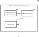
- Fig. 2 shows a machine learning method training system 200 according to various embodiments.
- the machine learning method training system 200 may include a measurement data determination circuit 202, an approximation circuit 204, and a training circuit 206.
- the measurement data determination circuit 202 may be configured to determine measurement data from a first sensor.
- the approximation circuit 204 may be configured to determine approximations of ground truths based on a second sensor.
- the training circuit 206 may be configured to train the machine learning method based on the measurement data and the approximations of ground truths, wherein approximations of ground truths of lower approximation quality have a lower effect on the training than approximations of ground truths of higher approximation quality.
- the measurement data determination circuit 202, the approximation circuit 204, and the training circuit 206 may be coupled with each other, e.g. via an electrical connection 208, such as e.g. a cable or a computer bus or via any other suitable electrical connection to exchange electrical signals.
- an electrical connection 208 such as e.g. a cable or a computer bus or via any other suitable electrical connection to exchange electrical signals.
- a “circuit” may be understood as any kind of a logic implementing entity, which may be special purpose circuitry or a processor executing a program stored in a memory, firmware, or any combination thereof.
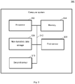
- Fig. 3 shows a computer system 300 with a plurality of computer hardware components configured to carry out steps of a computer implemented method for path planning according to various embodiments.
- the computer system 300 may include a processor 302, a memory 304, and a non-transitory data storage 306.
- a first sensor 308 and/or a second sensor 310 may be provided as part of the computer system 300 (like illustrated in Fig. 3 ), or may be provided external to the computer system 300.
- the processor 302 may carry out instructions provided in the memory 304.
- the non-transitory data storage 306 may store a computer program, including the instructions that may be transferred to the memory 304 and then executed by the processor 302.
- the first sensor 308 may be used for determining measurement data.
- the second sensor 310 may be used to determine ground truths.
- the processor 302, the memory 304, and the non-transitory data storage 306 may be coupled with each other, e.g. via an electrical connection 312, such as e.g. a cable or a computer bus or via any other suitable electrical connection to exchange electrical signals.
- the first sensor 308 and/or the second sensor 310 may be coupled to the computer system 300, for example via an external interface, or may be provided as parts of the computer system (in other words: internal to the computer system, for example coupled via the electrical connection 312).
- Coupled or “connection” are intended to include a direct “coupling” (for example via a physical link) or direct “connection” as well as an indirect “coupling” or indirect “connection” (for example via a logical link), respectively.
Landscapes
- Engineering & Computer Science (AREA)
- Physics & Mathematics (AREA)
- Theoretical Computer Science (AREA)
- General Physics & Mathematics (AREA)
- Radar, Positioning & Navigation (AREA)
- Remote Sensing (AREA)
- Software Systems (AREA)
- Artificial Intelligence (AREA)
- Evolutionary Computation (AREA)
- General Engineering & Computer Science (AREA)
- Data Mining & Analysis (AREA)
- Mathematical Physics (AREA)
- Computing Systems (AREA)
- Biophysics (AREA)
- Molecular Biology (AREA)
- General Health & Medical Sciences (AREA)
- Computational Linguistics (AREA)
- Biomedical Technology (AREA)
- Life Sciences & Earth Sciences (AREA)
- Health & Medical Sciences (AREA)
- Computer Networks & Wireless Communication (AREA)
- Computer Vision & Pattern Recognition (AREA)
- Medical Informatics (AREA)
- Traffic Control Systems (AREA)
- Radar Systems Or Details Thereof (AREA)
Abstract
Description
- The present disclosure relates to methods and systems for training a machine learning method.
- Artificial neural networks are a powerful tool for various tasks, in particular for classification or object detection.
- However, artificial neural networks have to be trained, usually using large data sets involving input data and output data which the artificial neural network is supposed to compute based on the input data. For example for artificial neural networks that are to work on sensor data, labelled data (which may be referred to as ground truth) may be required. These labelled data is usually obtained manually, which is cost intense and slow.
- Accordingly, there is a need to improve training of (artificial) neural networks.
- The present disclosure provides a computer implemented method, a computer system and a non-transitory computer readable medium according to the independent claims. Embodiments are given in the subclaims, the description and the drawings.
- In one aspect, the present disclosure is directed at a computer implemented method for training a machine learning method, the method comprising the following steps performed (in other words: carried out) by computer hardware components: determining measurement data from a first sensor; determining approximations of ground truths based on a second sensor; training the machine learning method based on the measurement data and the approximations of ground truths; wherein approximations of ground truths of lower approximation quality have a lower effect on the training than approximations of ground truths of higher approximation quality.
- In other words, approximations of ground truths which have a lower approximation quality may have less influence on the training.
- The method may allow handling inter-sensor perception discrepancies for machine learning without human intervention. For example, the method may provide automatic labelling of imperfect sensor and non-matched radar and lidar data for a machine learning model.
- The machine learning method may for example be an artificial neural network.
- According to another aspect, it is provided that approximations of ground truths of lower approximation quality have a lower effect on the training than approximations of ground truths of higher approximation quality by using an optimization criterion for the training, wherein the optimization criterion is based on a mapping. The mapping may reflect which regions of ground truth are reliable or not.
- According to another aspect, the optimization criterion is further based on an energy map of the measurement data. This additional optimization term may be used to address the shortcomings created by the first optimization term. The energy map may be represented by f̃ (xi ) and may represent the unobserved space
- According to another aspect, the optimization criterion comprises a cross entropy between the measurement data and the approximations of the ground truths.
- According to another aspect, the optimization criterion is based on a sum comprising a first summand based on the cross entropy and a second summand based on the energy map. This may ensure a training of the machine learning method to the annotated data, and at the same time ensure that the output does not deviate too much from the input data.
- According to another aspect, it is provided that approximations of ground truths of lower approximation quality have a lower effect on the training than approximations of ground truths of higher approximation quality by filtering out approximations of ground truths of lower approximation quality.
- According to another aspect, the filtering out comprises grouping the measurement data based on a look type. This may for example be done in the first step described below. The method may provide handling inter-sensor perception discrepancies for machine learning using radar looktypes.
- According to another aspect, the filtering out comprises identifying ground truths providing a negative influence on the training. This may for example be done in the second step described below.
- According to another aspect, the filtering out comprises determining a reliability map. This may for example be done in the third step described below.
- According to another aspect, entries of the reliability map are determined based on whether a perception is similar over the first sensor and the second sensor. For example, the reliability value of each ground truth region may be determined based on whether that region is perceived in a similar way over multiple sensors, for example a RADAR and a LIDAR.
- According to another aspect, the machine learning method is configured to classify objects.
- According to another aspect, the approximations of ground truths are determined based on the second sensor using an automated method (for example without human interaction or with only a limited amount of human interaction, which is faster than classification based on the measurement data of the first sensor would be).
- According to another aspect, the first sensor is a radar sensor. According to another aspect, the second sensor is a lidar sensor. However, it will be understood that any other two types of sensors may be used.
- In another aspect, the present disclosure is directed at a computer system, said computer system comprising a plurality of computer hardware components configured to carry out several or all steps of the computer implemented method described herein.
- The computer system may comprise a plurality of computer hardware components (for example a processor, for example processing unit or processing network, at least one memory, for example memory unit or memory network, and at least one non-transitory data storage). It will be understood that further computer hardware components may be provided and used for carrying out steps of the computer implemented method in the computer system. The non-transitory data storage and/or the memory unit may comprise a computer program for instructing the computer to perform several or all steps or aspects of the computer implemented method described herein, for example using the processing unit and the at least one memory unit.
- In another aspect, the present disclosure is directed at a non-transitory computer readable medium comprising instructions for carrying out several or all steps or aspects of the computer implemented method described herein. The computer readable medium may be configured as: an optical medium, such as a compact disc (CD) or a digital versatile disk (DVD); a magnetic medium, such as a hard disk drive (HDD); a solid state drive (SSD); a read only memory (ROM), such as a flash memory; or the like. Furthermore, the computer readable medium may be configured as a data storage that is accessible via a data connection, such as an internet connection. The computer readable medium may, for example, be an online data repository or a cloud storage.
- The present disclosure is also directed at a computer program for instructing a computer to perform several or all steps or aspects of the computer implemented method described herein.
- Exemplary embodiments and functions of the present disclosure are described herein in conjunction with the following drawings, showing schematically:
- Fig. 1
- a flow diagram illustrating a method for training a machine learning method according to various embodiments;
- Fig. 2
- a machine learning method training system according to various embodiments; and
- Fig. 3
- a computer system with a plurality of computer hardware components configured to carry out steps of a computer implemented method for training a machine learning method according to various embodiments.
- Various embodiments refer to a problem where, given a two dimensional grid of energy reflections from a radar sensor (for example an automotive radar sensor), a machine learning method (for example an artificial neural network) is required to predict whether a grid cell is free, occupied or unknown. A commonly used way to solve this problem is to collect large amount of input data, and then manually label them to each corresponding class ("free", "occupied", "unknown"). Usually, a large amount of labelled (in other words: annotated data) may be required, which may be expensive.
- Then, using a machine learning method, the mapping from the input signal to the semantic classes may be learned.
- Since radar signals may be non-interpretable for a non-expert, a Lidar sensor may be used to help with labeling. This may mean using a synchronized lidar sensor, and a human may annotate radar data. However, a typical Lidar scan contains hundreds of thousands of points; so manual labeling may be very expensive. To reduce cost, lidar data may be artificially labeled using some mathematical assumptions, since lidar has rich 3d information. In other words, to reduce cost, ground truth may be artificially generated using the data from a laser scanner (lidar sensor) which is synchronized with the radar sensor.
- Once such a ground truth is determined, there arises a matching problem between the two sensors. This may be due to the differences between their physical principles and also due to mounting and time synchronization. Therefore, an exact mapping from lidar sensor data to radar sensor data, both in time and space, may not always be feasible. As a result, the ground truth which is generated inexpensively may not align exactly with input data for each grid cell. When a machine learning algorithm is trained with such imperfect data, the results may be unacceptable.
- According to various embodiments, methods and system are provided with which a machine learning model may be trained using such imperfect data, and at the same time acceptable results may be reached.
- In an exemplary setup, the perception volume of both sensors may be different. Thus the labeled signal from lidar may be different from the signal of radar.
- According to various embodiments, the discrepancy between labels and the input signal (i.e. the measurement data, for example input radar signal) may be determined. According to various embodiments, the mapping from input radar signal to output segmentation mask may be learned.
- To train a (artificial) neural network to learn the mapping f(x) = y, where x may denote the input signal and y may denote the target signal, the cross entropy between the network prediction f(x) and the target variable y may be minimized. According to various embodiments, the input signal x may be a Cartesian grid representation of an environment perceived by an automotive radar sensor. The target variable y may be the grid representation of labels of the same environment created using lidar data.
- According to various embodiments, the input signal may be the radar energy and the output signal may be labels created using lidar data. The cross entropy CE in this case may be given by the following equation:

- Minimizing the above value may make the network prediction closer to labels. But it may be seen that there are many structures in labeled data which are not seen by the radar and vice versa.
- Using the above measure alone for optimization may force the network to learn some artifacts which may deliver unintended results. This may mean that it may be desired to avoid giving importance to unreliable regions. According to various embodiments, this may be done by first identifying reliable regions of ground truth which can be used for training and then exclude the rest during neural network optimization.
- The reliability value of each ground truth region may be determined based on whether that region is perceived in a similar way over multiple sensors, for example a RADAR and a LIDAR.
- A first step may be to identify the reliable areas of the ground truth. Let us denote this by the variable ri , where the subscript denotes grid cell i. A ground truth grid cell yi ∈ {free(0),occupied(1),unknown(2)}, That means a grid cell in ground truth can have any of the above three values 0 (indicating the ground truth "free"), 1 (indicating the ground truth "occupied"), or 2 (indicating the ground truth "unknown").
- According to various embodiments, it may be started by setting all N ground truth cells to reliable, i.e. := 1∀ i ∈ N. A ground truth grid cell i may be considered unreliable, if there is a conflict between lidar and radar sensor measurements. One possible definition of this conflict is as follows, wherein T1 and T2 are thresholds which are determined empirically for each radar looktype:
ri := 0 if xi > T1 && yi ≠ 1,
or x i < T2 && yi > 0,
or yi == 2. - T1 may be T_high, which will be described below. T2 may be T_low, which will be described below.
- Regions where xi > T1 may provide hints that that radar may indicate that it is occupied but if yi is not 1, then the Lidar sensor data may contradict with it. Then the cell may be marked as unreliable.
- Similarly, if xi < T2, then the radar may claim a free cell. But if the Lidar indicates the cell as occupied or unknown, then also the cell may become unreliable.
- Now, this may be incorporated in the afore mentioned cross entropy (or cross entropy loss):


- The above term when optimized may ignore the unreliable regions of ground truth, but may not be able to identify and suppress the noise and artifacts present in the radar input signal. This may result in neural network predict incorrect labels for regions which are not even observable due reasons like occlusion. According to various embodiments, this may be avoided may making the network learn the unobserved region of ground truth. The large unobserved region of the ground truth will be mostly noise in radar input signal. To learn this region, another output may be add to the network. The additional output may be denoted as f̃(xi ). Furthermore, the ground truth may be modify from to ỹ as follows:


- The combined optimization criterion CL (or optimization term), which is minimized when training the network, may then be

- According to various embodiments, the prior knowledge about the data (for example radar reflections) may be used to filter out parts of automatically generated ground truth which is expected to harm the model training process. The method may work in three steps:
In a first step, the radar reflections may be grouped based on their look types, and a radar frame may be assembled by grouping reflections from radars which report the same look type. - In a second step, harmful parts of automatically generated ground truth may be identified. For example, given a 2D grid of radar reflections, it may be very likely that grid cells with high reflected energy are occupied. At the same time, grid cells with negligible energy may be likely to be empty or unobserved. Two thresholds T_high and T_low may be introduced for the radar reflected energy to identify those grid cells which are reliably labeled by the automatic ground truth. The above described knowledge may be used to set high importance to cells which have reliable labels.
- T_high may be the minimum energy value above which it may be sure that occluded labels given by automatic ground truth are reliable. T_low may be the maximum energy value, so that for those grid cells with energy less than T_low are reliably labeled as not occupied by the automatic ground truth.
- To identify stable T_high and T_low, conditioning based on looktype may be used. It may be observed that reflected energy from multiple radars shows a similar pattern when they belong to same look type.
- In a third step, the above information may be integrated into training. The reliability of each cell may be encoded to a binary value. This may lead to a reliability map, where each cell may be marked as reliable (for example binary value of 1 or true) or not reliable (for example binary value 0 or false). This map may then be used at the time of optimizing the neural network weights to ignore the regions where we suspect corrupt labels. This is done by weighting the loss function (i.e. the function which is optimized when training the neural network) using the reliability map.
-
Fig. 1 shows a flow diagram 100 illustrating a method for training a machine learning method according to various embodiments. At 102, measurement data from a first sensor may be determined. At 104, approximations of ground truths may be determined based on a second sensor. At 106, the machine learning method may be trained based on the measurement data and the approximations of ground truths, wherein approximations of ground truths of lower approximation quality have a lower effect on the training than approximations of ground truths of higher approximation quality. - According to various embodiments, it may be provided that approximations of ground truths of lower approximation quality have a lower effect on the training than approximations of ground truths of higher approximation quality by using an optimization criterion for the training, wherein the optimization criterion is based on a mapping.
- According to various embodiments, the optimization criterion may further be based on an energy map of the measurement data.
- According to various embodiments, the optimization criterion may include a cross entropy between the measurement data and the approximations of the ground truths.
- According to various embodiments, the optimization criterion may be based on a sum comprising a first summand based on the cross entropy and a second summand based on the energy map.
- According to various embodiments, it may be provided that approximations of ground truths of lower approximation quality have a lower effect on the training than approximations of ground truths of higher approximation quality by filtering out approximations of ground truths of lower approximation quality.
- According to various embodiments, the filtering out may include grouping the measurement data based on a look type.
- According to various embodiments, the filtering out may include identifying ground truths providing a negative influence on the training.
- According to various embodiments, the filtering out may include determining a reliability map.
- According to various embodiments, entries of the reliability map may be determined based on whether a perception is similar over the first sensor and the second sensor.
- According to various embodiments, the machine learning method may be configured to classify objects.
- According to various embodiments, the approximations of ground truths may be determined based on the second sensor using an automated method.
- According to various embodiments, the first sensor may be a radar sensor.
- According to various embodiments, the second sensor may be a lidar sensor.
- Each of the
steps -
Fig. 2 shows a machine learningmethod training system 200 according to various embodiments. The machine learningmethod training system 200 may include a measurementdata determination circuit 202, anapproximation circuit 204, and atraining circuit 206. - The measurement
data determination circuit 202 may be configured to determine measurement data from a first sensor. - The
approximation circuit 204 may be configured to determine approximations of ground truths based on a second sensor. - The
training circuit 206 may be configured to train the machine learning method based on the measurement data and the approximations of ground truths, wherein approximations of ground truths of lower approximation quality have a lower effect on the training than approximations of ground truths of higher approximation quality. - The measurement
data determination circuit 202, theapproximation circuit 204, and thetraining circuit 206 may be coupled with each other, e.g. via anelectrical connection 208, such as e.g. a cable or a computer bus or via any other suitable electrical connection to exchange electrical signals. - A "circuit" may be understood as any kind of a logic implementing entity, which may be special purpose circuitry or a processor executing a program stored in a memory, firmware, or any combination thereof.
-
Fig. 3 shows acomputer system 300 with a plurality of computer hardware components configured to carry out steps of a computer implemented method for path planning according to various embodiments. Thecomputer system 300 may include aprocessor 302, amemory 304, and anon-transitory data storage 306. Afirst sensor 308 and/or asecond sensor 310 may be provided as part of the computer system 300 (like illustrated inFig. 3 ), or may be provided external to thecomputer system 300. - The
processor 302 may carry out instructions provided in thememory 304. Thenon-transitory data storage 306 may store a computer program, including the instructions that may be transferred to thememory 304 and then executed by theprocessor 302. Thefirst sensor 308 may be used for determining measurement data. Thesecond sensor 310 may be used to determine ground truths. - The
processor 302, thememory 304, and thenon-transitory data storage 306 may be coupled with each other, e.g. via anelectrical connection 312, such as e.g. a cable or a computer bus or via any other suitable electrical connection to exchange electrical signals. Thefirst sensor 308 and/or thesecond sensor 310 may be coupled to thecomputer system 300, for example via an external interface, or may be provided as parts of the computer system (in other words: internal to the computer system, for example coupled via the electrical connection 312). - The terms "coupling" or "connection" are intended to include a direct "coupling" (for example via a physical link) or direct "connection" as well as an indirect "coupling" or indirect "connection" (for example via a logical link), respectively.
- It will be understood that what has been described for one of the methods above may analogously hold true for the machine learning
method training system 200 and/or for thecomputer system 300. -
- 100
- flow diagram illustrating a method for training a machine learning method according to various embodiments
- 102
- step of determining measurement data from a first sensor
- 104
- step of determining approximations of ground truths based on a second sensor
- 106
- training the machine learning method based on the measurement data and the approximations of ground truths
- 200
- machine learning method training system according to various embodiments
- 202
- measurement data determination circuit
- 204
- approximation circuit
- 206
- training circuit
- 208
- connection
- 300
- computer system according to various embodiments
- 302
- processor
- 304
- memory
- 306
- non-transitory data storage
- 308
- first sensor
- 310
- second sensor
- 312
- connection
Claims (15)
- Computer implemented method for training a machine learning method, the method comprising the following steps carried out by computer hardware components:- determining (102) measurement data from a first sensor;- determining (104) approximations of ground truths based on a second sensor; and- training (106) the machine learning method based on the measurement data and the approximations of ground truths;
wherein approximations of ground truths of lower approximation quality have a lower effect on the training than approximations of ground truths of higher approximation quality. - The computer implemented method of claim 1,
wherein it is provided that approximations of ground truths of lower approximation quality have a lower effect on the training than approximations of ground truths of higher approximation quality by using an optimization criterion for the training, wherein the optimization criterion is based on a mapping. - The computer implemented method of claim 2,
wherein the optimization criterion is further based on an energy map of the measurement data. - The computer implemented method of at least one of claims 2 or 3,
wherein the optimization criterion comprises a cross entropy between the measurement data and the approximations of the ground truths. - The computer implemented method of claims 3 and 4,
wherein the optimization criterion is based on a sum comprising a first summand based on the cross entropy and a second summand based on the energy map. - The computer implemented method of at least one of claims 1 to 5, wherein it is provided that approximations of ground truths of lower approximation quality have a lower effect on the training than approximations of ground truths of higher approximation quality by filtering out approximations of ground truths of lower approximation quality.
- The computer implemented method of claim 6,
wherein the filtering out comprises grouping the measurement data based on a look type. - The computer implemented method of at least one of claims 6 or 7, wherein the filtering out comprises identifying ground truths providing a negative influence on the training.
- The computer implemented method of at least one of claims 6 to 8, wherein the filtering out comprises determining a reliability map.
- The computer implemented method of claim 9,
wherein entries of the reliability map are determined based on whether a perception is similar over the first sensor and the second sensor. - The computer implemented method of at least one of claims 1 to 10, wherein the machine learning method is configured to classify objects.
- The computer implemented method of at least one of claims 1 to 11, wherein the approximations of ground truths are determined based on the second sensor using an automated method.
- The computer implemented method of at least one of claims 1 to 12, wherein the first sensor is a radar sensor; and/ or.
wherein the second sensor is a lidar sensor. - Computer system (300), the computer system being configured to carry out the computer implemented method of at least one of claims 1 to 13.
- Non-transitory computer readable medium comprising instructions for carrying out the computer implemented method of at least one of claims 1 to 13.
Priority Applications (3)
| Application Number | Priority Date | Filing Date | Title |
|---|---|---|---|
| EP20201283.7A EP3982297B1 (en) | 2020-10-12 | 2020-10-12 | Methods and systems for training a machine learning method |
| US17/495,332 US12585983B2 (en) | 2020-10-12 | 2021-10-06 | Methods and systems for training a machine learning method using high quality ground truth approximations |
| CN202111181016.3A CN114358108A (en) | 2020-10-12 | 2021-10-11 | Method and system for training machine learning method |
Applications Claiming Priority (1)
| Application Number | Priority Date | Filing Date | Title |
|---|---|---|---|
| EP20201283.7A EP3982297B1 (en) | 2020-10-12 | 2020-10-12 | Methods and systems for training a machine learning method |
Publications (2)
| Publication Number | Publication Date |
|---|---|
| EP3982297A1 true EP3982297A1 (en) | 2022-04-13 |
| EP3982297B1 EP3982297B1 (en) | 2026-04-08 |
Family
ID=72840350
Family Applications (1)
| Application Number | Title | Priority Date | Filing Date |
|---|---|---|---|
| EP20201283.7A Active EP3982297B1 (en) | 2020-10-12 | 2020-10-12 | Methods and systems for training a machine learning method |
Country Status (3)
| Country | Link |
|---|---|
| US (1) | US12585983B2 (en) |
| EP (1) | EP3982297B1 (en) |
| CN (1) | CN114358108A (en) |
Families Citing this family (2)
| Publication number | Priority date | Publication date | Assignee | Title |
|---|---|---|---|---|
| US12263865B1 (en) * | 2022-09-08 | 2025-04-01 | Waymo Llc | Validation of occlusions identified within autonomous vehicle driving environments |
| US20250005426A1 (en) * | 2023-06-27 | 2025-01-02 | Robert Bosch Gmbh | System and method to train and evaluate a deep-learning system on multiple ground-truth sources subject to measurement errors |
Citations (1)
| Publication number | Priority date | Publication date | Assignee | Title |
|---|---|---|---|---|
| US20200217950A1 (en) * | 2019-01-07 | 2020-07-09 | Qualcomm Incorporated | Resolution of elevation ambiguity in one-dimensional radar processing |
Family Cites Families (10)
| Publication number | Priority date | Publication date | Assignee | Title |
|---|---|---|---|---|
| WO2008097694A1 (en) * | 2007-02-05 | 2008-08-14 | Andrew Corporation | System and method for optimizing location estimate of mobile unit |
| US8645819B2 (en) * | 2011-06-17 | 2014-02-04 | Xerox Corporation | Detection and extraction of elements constituting images in unstructured document files |
| US10612939B2 (en) * | 2014-01-02 | 2020-04-07 | Microsoft Technology Licensing, Llc | Ground truth estimation for autonomous navigation |
| JP6548376B2 (en) * | 2014-10-06 | 2019-07-24 | 日本電産株式会社 | Radar system, radar signal processing device, vehicle travel control device and method, and computer program |
| US10166991B1 (en) * | 2017-12-01 | 2019-01-01 | GM Global Technology Operations LLC | Method and apparatus of selective sensing mechanism in vehicular crowd-sensing system |
| US10817752B2 (en) * | 2018-05-31 | 2020-10-27 | Toyota Research Institute, Inc. | Virtually boosted training |
| US12399015B2 (en) * | 2019-04-12 | 2025-08-26 | Nvidia Corporation | Neural network training using ground truth data augmented with map information for autonomous machine applications |
| US11250296B2 (en) * | 2019-07-24 | 2022-02-15 | Nvidia Corporation | Automatic generation of ground truth data for training or retraining machine learning models |
| US11299169B2 (en) * | 2020-01-24 | 2022-04-12 | Ford Global Technologies, Llc | Vehicle neural network training |
| WO2022056279A1 (en) * | 2020-09-11 | 2022-03-17 | Waymo Llc | Estimating ground truth object keypoint labels for sensor readings |
-
2020
- 2020-10-12 EP EP20201283.7A patent/EP3982297B1/en active Active
-
2021
- 2021-10-06 US US17/495,332 patent/US12585983B2/en active Active
- 2021-10-11 CN CN202111181016.3A patent/CN114358108A/en active Pending
Patent Citations (1)
| Publication number | Priority date | Publication date | Assignee | Title |
|---|---|---|---|---|
| US20200217950A1 (en) * | 2019-01-07 | 2020-07-09 | Qualcomm Incorporated | Resolution of elevation ambiguity in one-dimensional radar processing |
Non-Patent Citations (3)
| Title |
|---|
| MAGGIOLO LUCA ET AL: "Improving Maps from CNNs Trained with Sparse, Scribbled Ground Truths Using Fully Connected CRFs", IGARSS 2018 - 2018 IEEE INTERNATIONAL GEOSCIENCE AND REMOTE SENSING SYMPOSIUM, IEEE, 22 July 2018 (2018-07-22), pages 2099 - 2102, XP033437118, DOI: 10.1109/IGARSS.2018.8517947 * |
| MAGGIORI EMMANUEL ET AL: "Convolutional Neural Networks for Large-Scale Remote-Sensing Image Classification", vol. 55, no. 2, 1 February 2017 (2017-02-01), US, pages 645 - 657, XP055790633, ISSN: 0196-2892, Retrieved from the Internet <URL:https://ieeexplore.ieee.org/stampPDF/getPDF.jsp?tp=&arnumber=7592858&ref=aHR0cHM6Ly9pZWVleHBsb3JlLmllZWUub3JnL2Fic3RyYWN0L2RvY3VtZW50Lzc1OTI4NTg/Y2FzYV90b2tlbj1CcmZTZUFKN0FaSUFBQUFBOnFTX1VhSGpRY2RDWkt2TzU0TXg5aXA5LXcyd2p4dWNmcng2dWpGQ3BVSm8xWkFHWXhDMFo3R0VGZ1A1LU9TQ0F2SlZkTTE4> DOI: 10.1109/TGRS.2016.2612821 * |
| NIMA TAJBAKHSH ET AL: "Convolutional Neural Networks for Medical Image Analysis: Full Training or Fine Tuning?", ARXIV.ORG, CORNELL UNIVERSITY LIBRARY, 201 OLIN LIBRARY CORNELL UNIVERSITY ITHACA, NY 14853, 2 June 2017 (2017-06-02), XP080767115, DOI: 10.1109/TMI.2016.2535302 * |
Also Published As
| Publication number | Publication date |
|---|---|
| US12585983B2 (en) | 2026-03-24 |
| EP3982297B1 (en) | 2026-04-08 |
| CN114358108A (en) | 2022-04-15 |
| US20220114489A1 (en) | 2022-04-14 |
Similar Documents
| Publication | Publication Date | Title |
|---|---|---|
| US10867244B2 (en) | Method and apparatus for machine learning | |
| US11514308B2 (en) | Method and apparatus for machine learning | |
| WO2021232229A1 (en) | Virtual scene generation method and apparatus, computer device and storage medium | |
| US12462544B2 (en) | Method and apparatus for image classification | |
| US7013047B2 (en) | System and method for performing edge detection in an image | |
| CN110956255A (en) | Difficult sample mining method, device, electronic device, and computer-readable storage medium | |
| JP2022501681A (en) | Depth image complement method and device, computer readable storage medium | |
| US12585983B2 (en) | Methods and systems for training a machine learning method using high quality ground truth approximations | |
| US20230021674A1 (en) | Storage medium, machine learning method, and machine learning apparatus | |
| IL295764A (en) | Generating performance forecasts with uncertainty margins | |
| US9349075B2 (en) | Image processing apparatus and method for detecting transparent object in image | |
| CN115150250A (en) | Internet of things abnormal root cause positioning method and device based on causal learning | |
| US8301584B2 (en) | System and method for adaptive pruning | |
| CN117494638B (en) | Verification method and verification platform for chip functions, electronic equipment and storage medium | |
| CN111681204B (en) | CT rib fracture focus relation modeling method and device based on graph neural network | |
| CN120182755A (en) | A method and device for mining difficult examples in target detection | |
| US20230260259A1 (en) | Method and device for training a neural network | |
| CN115953430B (en) | Video single-target tracking method and system based on improved batch sample loss function | |
| US12566820B2 (en) | Method and apparatus for classifying data | |
| EP4075327A1 (en) | Methods and systems for training a machine learning method for determining pre-determined points in an image | |
| CN120162670A (en) | A board fault location method, system, device and medium | |
| CN113298822A (en) | Point cloud data selection method and device, equipment and storage medium | |
| CN112053319A (en) | Image processing method and device | |
| CN118690310B (en) | A multi-modal bridge data uploading method, device, equipment and medium | |
| WO2024174136A1 (en) | Method for improving prediction accuracy of ai model, electronic device and medium |
Legal Events
| Date | Code | Title | Description |
|---|---|---|---|
| PUAI | Public reference made under article 153(3) epc to a published international application that has entered the european phase |
Free format text: ORIGINAL CODE: 0009012 |
|
| STAA | Information on the status of an ep patent application or granted ep patent |
Free format text: STATUS: THE APPLICATION HAS BEEN PUBLISHED |
|
| AK | Designated contracting states |
Kind code of ref document: A1 Designated state(s): AL AT BE BG CH CY CZ DE DK EE ES FI FR GB GR HR HU IE IS IT LI LT LU LV MC MK MT NL NO PL PT RO RS SE SI SK SM TR |
|
| STAA | Information on the status of an ep patent application or granted ep patent |
Free format text: STATUS: REQUEST FOR EXAMINATION WAS MADE |
|
| 17P | Request for examination filed |
Effective date: 20221012 |
|
| RBV | Designated contracting states (corrected) |
Designated state(s): AL AT BE BG CH CY CZ DE DK EE ES FI FR GB GR HR HU IE IS IT LI LT LU LV MC MK MT NL NO PL PT RO RS SE SI SK SM TR |
|
| RAP3 | Party data changed (applicant data changed or rights of an application transferred) |
Owner name: APTIV TECHNOLOGIES LIMITED |
|
| RAP1 | Party data changed (applicant data changed or rights of an application transferred) |
Owner name: APTIV TECHNOLOGIES AG |
|
| RAP3 | Party data changed (applicant data changed or rights of an application transferred) |
Owner name: APTIV TECHNOLOGIES AG |
|
| STAA | Information on the status of an ep patent application or granted ep patent |
Free format text: STATUS: EXAMINATION IS IN PROGRESS |
|
| 17Q | First examination report despatched |
Effective date: 20250805 |
|
| GRAP | Despatch of communication of intention to grant a patent |
Free format text: ORIGINAL CODE: EPIDOSNIGR1 |
|
| STAA | Information on the status of an ep patent application or granted ep patent |
Free format text: STATUS: GRANT OF PATENT IS INTENDED |
|
| RIC1 | Information provided on ipc code assigned before grant |
Ipc: G06N 3/08 20060101AFI20251128BHEP Ipc: G06N 20/00 20190101ALI20251128BHEP Ipc: G01S 7/41 20060101ALI20251128BHEP Ipc: G01S 13/72 20060101ALI20251128BHEP Ipc: G01S 13/86 20060101ALI20251128BHEP Ipc: G06N 3/0464 20230101ALI20251128BHEP Ipc: G06N 3/09 20230101ALI20251128BHEP Ipc: G06N 3/0895 20230101ALI20251128BHEP Ipc: G01S 7/40 20060101ALN20251128BHEP Ipc: G01S 17/931 20200101ALN20251128BHEP Ipc: G01S 13/931 20200101ALN20251128BHEP |
|
| RIC1 | Information provided on ipc code assigned before grant |
Ipc: G06N 3/08 20060101AFI20251218BHEP Ipc: G06N 20/00 20190101ALI20251218BHEP Ipc: G01S 7/41 20060101ALI20251218BHEP Ipc: G01S 13/72 20060101ALI20251218BHEP Ipc: G01S 13/86 20060101ALI20251218BHEP Ipc: G06N 3/0464 20230101ALI20251218BHEP Ipc: G06N 3/09 20230101ALI20251218BHEP Ipc: G06N 3/0895 20230101ALI20251218BHEP Ipc: G01S 7/40 20060101ALN20251218BHEP Ipc: G01S 17/931 20200101ALN20251218BHEP Ipc: G01S 13/931 20200101ALN20251218BHEP |
|
| INTG | Intention to grant announced |
Effective date: 20260105 |
|
| P01 | Opt-out of the competence of the unified patent court (upc) registered |
Free format text: CASE NUMBER: UPC_APP_0001749_3982297/2026 Effective date: 20260119 |
|
| GRAS | Grant fee paid |
Free format text: ORIGINAL CODE: EPIDOSNIGR3 |
|
| GRAA | (expected) grant |
Free format text: ORIGINAL CODE: 0009210 |
|
| STAA | Information on the status of an ep patent application or granted ep patent |
Free format text: STATUS: THE PATENT HAS BEEN GRANTED |
|
| AK | Designated contracting states |
Kind code of ref document: B1 Designated state(s): AL AT BE BG CH CY CZ DE DK EE ES FI FR GB GR HR HU IE IS IT LI LT LU LV MC MK MT NL NO PL PT RO RS SE SI SK SM TR |
|
| REG | Reference to a national code |
Ref country code: CH Ref legal event code: F10 Free format text: ST27 STATUS EVENT CODE: U-0-0-F10-F00 (AS PROVIDED BY THE NATIONAL OFFICE) Effective date: 20260408 Ref country code: GB Ref legal event code: FG4D |
|
| REG | Reference to a national code |
Ref country code: DE Ref legal event code: R096 Ref document number: 602020069937 Country of ref document: DE |