EP3982219A1 - Visual interlock specification for industrial automation - Google Patents
Visual interlock specification for industrial automation Download PDFInfo
- Publication number
- EP3982219A1 EP3982219A1 EP20200904.9A EP20200904A EP3982219A1 EP 3982219 A1 EP3982219 A1 EP 3982219A1 EP 20200904 A EP20200904 A EP 20200904A EP 3982219 A1 EP3982219 A1 EP 3982219A1
- Authority
- EP
- European Patent Office
- Prior art keywords
- rule
- cause
- topology model
- industrial process
- effect
- Prior art date
- Legal status (The legal status is an assumption and is not a legal conclusion. Google has not performed a legal analysis and makes no representation as to the accuracy of the status listed.)
- Pending
Links
Images




Classifications
-
- G—PHYSICS
- G05—CONTROLLING; REGULATING
- G05B—CONTROL OR REGULATING SYSTEMS IN GENERAL; FUNCTIONAL ELEMENTS OF SUCH SYSTEMS; MONITORING OR TESTING ARRANGEMENTS FOR SUCH SYSTEMS OR ELEMENTS
- G05B19/00—Program-control systems
- G05B19/02—Program-control systems electric
- G05B19/18—Numerical control [NC], i.e. automatically operating machines, in particular machine tools, e.g. in a manufacturing environment, so as to execute positioning, movement or co-ordinated operations by means of program data in numerical form
- G05B19/4155—Numerical control [NC], i.e. automatically operating machines, in particular machine tools, e.g. in a manufacturing environment, so as to execute positioning, movement or co-ordinated operations by means of program data in numerical form characterised by program execution, i.e. part program or machine function execution, e.g. selection of a program
-
- G—PHYSICS
- G05—CONTROLLING; REGULATING
- G05B—CONTROL OR REGULATING SYSTEMS IN GENERAL; FUNCTIONAL ELEMENTS OF SUCH SYSTEMS; MONITORING OR TESTING ARRANGEMENTS FOR SUCH SYSTEMS OR ELEMENTS
- G05B19/00—Program-control systems
- G05B19/02—Program-control systems electric
- G05B19/418—Total factory control, i.e. centrally controlling a plurality of machines, e.g. direct or distributed numerical control [DNC], flexible manufacturing systems [FMS], integrated manufacturing systems [IMS] or computer integrated manufacturing [CIM]
- G05B19/41885—Total factory control, i.e. centrally controlling a plurality of machines, e.g. direct or distributed numerical control [DNC], flexible manufacturing systems [FMS], integrated manufacturing systems [IMS] or computer integrated manufacturing [CIM] characterised by modeling, simulation of the manufacturing system
-
- H—ELECTRICITY
- H04—ELECTRIC COMMUNICATION TECHNIQUE
- H04L—TRANSMISSION OF DIGITAL INFORMATION, e.g. TELEGRAPHIC COMMUNICATION
- H04L41/00—Arrangements for maintenance, administration or management of data switching networks, e.g. of packet switching networks
- H04L41/22—Arrangements for maintenance, administration or management of data switching networks, e.g. of packet switching networks comprising specially adapted graphical user interfaces [GUI]
-
- G—PHYSICS
- G05—CONTROLLING; REGULATING
- G05B—CONTROL OR REGULATING SYSTEMS IN GENERAL; FUNCTIONAL ELEMENTS OF SUCH SYSTEMS; MONITORING OR TESTING ARRANGEMENTS FOR SUCH SYSTEMS OR ELEMENTS
- G05B2219/00—Program-control systems
- G05B2219/30—Nc systems
- G05B2219/32—Operator till task planning
- G05B2219/32085—Layout of factory, facility, cell, production system planning
-
- G—PHYSICS
- G05—CONTROLLING; REGULATING
- G05B—CONTROL OR REGULATING SYSTEMS IN GENERAL; FUNCTIONAL ELEMENTS OF SUCH SYSTEMS; MONITORING OR TESTING ARRANGEMENTS FOR SUCH SYSTEMS OR ELEMENTS
- G05B2219/00—Program-control systems
- G05B2219/30—Nc systems
- G05B2219/32—Operator till task planning
- G05B2219/32088—Master production planning, highest level
-
- G—PHYSICS
- G05—CONTROLLING; REGULATING
- G05B—CONTROL OR REGULATING SYSTEMS IN GENERAL; FUNCTIONAL ELEMENTS OF SUCH SYSTEMS; MONITORING OR TESTING ARRANGEMENTS FOR SUCH SYSTEMS OR ELEMENTS
- G05B2219/00—Program-control systems
- G05B2219/30—Nc systems
- G05B2219/32—Operator till task planning
- G05B2219/32168—Generation and analysis of synthesis rules for petrinet
-
- Y—GENERAL TAGGING OF NEW TECHNOLOGICAL DEVELOPMENTS; GENERAL TAGGING OF CROSS-SECTIONAL TECHNOLOGIES SPANNING OVER SEVERAL SECTIONS OF THE IPC; TECHNICAL SUBJECTS COVERED BY FORMER USPC CROSS-REFERENCE ART COLLECTIONS [XRACs] AND DIGESTS
- Y02—TECHNOLOGIES OR APPLICATIONS FOR MITIGATION OR ADAPTATION AGAINST CLIMATE CHANGE
- Y02P—CLIMATE CHANGE MITIGATION TECHNOLOGIES IN THE PRODUCTION OR PROCESSING OF GOODS
- Y02P90/00—Enabling technologies with a potential contribution to greenhouse gas [GHG] emissions mitigation
- Y02P90/02—Total factory control, e.g. smart factories, flexible manufacturing systems [FMS] or integrated manufacturing systems [IMS]
Definitions
- the invention relates to the field of methods for industrial processes, particularly for industrial plants and/or processes, for instance in chemical, mechanical, and/or other production and/or handling processes.
- the invention further relates to a computer-readable storage medium, an artificial neural network, ANN, and to a use.
- interlocks For a description of industrial plants and/or processes, in many cases so-called "interlocks" are used. Algorithms may perform those interlock specifications, e.g. by taking plant topology models from process engineers as a basis for their construction. However, in at least some cases, a safety engineer, service personnel and/or other persons whose work is related to these plants and/or processes, may not trust such algorithms, for example in cases when they are run automatically, and may thus fall back to manual interlock specification, which may be laborious and error-prone.
- One aspect relates to a method for visualizing a rule of an industrial process or processing system.
- the method comprises the steps of:
- Providing a topology model of the industrial process or processing system wherein the industrial process or processing system comprises at least one sensor and at least one actuator; Attributing the topology model with a rule, wherein the rule comprises a triple ⁇ cause, traversal, effect >, wherein:
- the industrial process may be an industrial automation application and/or an industrial process, particularly in an industrial plant, for instance in chemical, mechanical, and/or other production and/or handling processes.
- the rule - or a plurality of rules - may be part of a so-called interlock specification, which describes at least some aspects of the industrial process.
- Rules may link two or more devices, e.g. based on a functionality on which the devices are interlocked.
- At least some interlock specifications may comprise rules, which may represent the devices' relations, e.g. their functional and/or other relations.
- Rules may comprise safety restrictions. For example, a pump may only be started if a valve on its outlet is opened, in order to prevent overpressure.
- Visualizing may be performed on a visual interface of a computing device, e.g. on a display, a screen, a touch-screen, a beamer, and/or the like.
- the visualizing may comprise generating a visual specification, e.g. of an interlock specification.
- the visualizing may be implemented as a computer-implemented method.
- the topology model of the industrial process may describe by visual means elements of the process or plants and their connectivity, e.g. pipes, vessels, etc. for carrying fluids and/or media, electric connections, mechanical, logical, and/or other connections.
- the topology model comprises at least one sensor and one actuator. These devices of the topology model, of course, strongly depend on the kind of process or plant they are used in.
- Sensors may, e.g., comprise a metering device for pressure, temperature, light, sound, etc., including complex devices, e.g. for distances, flows, chemical analyses and/or for further purpose.
- Actuators may, e.g., comprise switches, valves, heaters, coolers, mixers, etc. that are configured to make a physical effect.
- the topology model is attributed with a rule - or a plurality of rules -, wherein each rule comprises a triple ⁇ cause, traversal, effect >.
- the rule may comprise further entries.
- the entry "cause” comprises a range of values from the at least one sensor. The range of values may come directly from one or more sensors, or it may be pre-processed and/or a result of linking several sensors.
- the entry "effect” comprises any action performed by the actuator (or a plurality of them), depending on the type of actuator.
- the entry “traversal” comprises a relation between the cause and the effect.
- One or more causes may contribute to one or more effects.
- One or more causes may be logically (AND, OR, ...) and/or otherwise connected, e.g. via functions.
- One or more effect may be logically and/or otherwise connected, e.g. via functions.
- Marking the cause, the traversal and/or the effect may, e.g., be implemented by a click and/or another input on one or more sensors, on one or more actuators, on one or more traversal paths of the topology model, and/or by marking a rule (or "line") of the interlock specification.
- the visualizing of the elements of the rule in the topology model may, e.g., be implemented by highlighting the components impacted, e.g. by colouring the related elements and/or their backgrounds. Additionally or as an alternative, the related rule may be shown, e.g. on the visual interface of a computing device. The visualizing may be accompanied by further actions.
- This may provide an improved capability for accessing a behaviour of industrial plants and/or processes. It may advantageously contribute to a visual interlock specification that provides safety engineers and/or other persons working with the process or plant with visual feedback on algorithmic interlock specifications. As a further result, this method may allow faster engineering of interlocks, may reuse existing domain-specific knowledge, may be less error-prone, and may reduce or avoid costly inconsistencies in specifications, e.g. in an interlock specification and/or other specifications of plants and/or processes.
- the topology model is attributed with a rule, based on visual means. This may be performed, e.g., by marking a cause and an effect - e.g. by "clicking" on them - and writing and/or visually programming a further relation between the cause and the effect. This further contributes to an intuitive handling of the model.
- the method further comprises the step of approving or acknowledging the rule, particularly an interlock detected by the rule. This may be done by a safety engineer and/or other personnel responsible for the process or plant. This may advantageously contribute to a higher level of trust in the specification(s).
- the method further comprises the step of rejecting the rule, particularly an interlock detected by the rule. This may advantageously be part of a fast and intuitive "debugging process" of the process' or plant's specification(s).
- the method further comprises the step of refining the rule, particularly an interlock, by performing at least one of: adding a further cause; adding a further effect; adding a further traversal; and/or adding a further element to the rule.
- the further element may, e.g., be a comment, a further output (e.g. an acoustic signal, a message, etc.), and/or a connection e.g. to a database or another interface.
- the rule-triple may thus become an n-tuple (with n > 3). This may advantageously contribute to a more intuitive way of engineering the plant.
- the approving, rejecting, and/or refining may be tracked, e.g. by means of a logging journal.
- the method further comprises the step of generating the topology model of the industrial process from a Piping-and-Instrumentation Diagram, P&ID, of the industrial process.
- P&ID Piping-and-Instrumentation Diagram
- the topology model comprises a plurality of rules. This may bring the benefit of being able to deal with complexity. So far, P&IDs, C&E (Cause & Effect) matrices, and/or further means may be used, which may be less intuitive than methods that comprise visualizing steps.
- the cognitive load of analysing complex P&IDs with thousands of elements and incorporating various safety regulations and customer requirements may also lead to oversights, e.g., missed required interlocks. While C&E matrices are typically thoroughly reviewed, errors or gaps may propagate into the automation system and cause harm to equipment or human workers. Furthermore, expensive clarifications and feedback loops between safety engineer and control engineer may be required.
- Rule-based engineering approaches using interlock specifications may offer a good compromise between highly optimized plants and reusable plant knowledge in the form of interlocking rules. However, they may suffer due to an insufficiently intuitive user feedback on how a rule was applied and which subset of the plant topology was involved. This may be a reason why at least some safety engineers do not rely on these tools. Hence, the methods as described above and/or below may contribute to improve this situation.
- the method further comprises the step of applying at least one step of the methods as described above and/or below to each rule of the plurality of rules.
- this semi-automated method - and also a system that is configured to run this method - may contribute to enable safety engineers to quickly generate C&E matrices improving or assuring correctness via visual feedback.
- Applying the methods may comprise to feed P&I diagrams by a process engineer for a process plant into a software tool, where a rule engine may process them to generate interlocks based on pre-specified, domain-specific rules.
- the result may be displayed, for instance, as a visual overlay to the P&I diagram or topology model, which includes marking up the causing equipment, the traversal paths, and the effected equipment.
- a process engineer may evaluate this visual representation and approve, reject, correct and/or otherwise deal with the generated Cause & Effect relationships.
- the approval step may be advantage due to a high heterogeneity of at least some industrial plants with many possibilities of assembling the equipment. Furthermore, this may improve the safety engineer's trust to trust in the methods.
- the method further comprises the step of generating a Cause & Effect, C&E, matrix from the topology model of the industrial process. Since at least some persons trust this representation more than other methods, this advantageously may help to close "media breaks" between several representations used by different engineers.
- the method further comprises the step of generating a Control Logic according to IEC 61131-3 from the C&E matrix of the industrial process. This advantageously may make at least some parts or aspects of an interlock specification directly applicable to processes or sub-processes of a plant.
- the method further comprises the step of generating a Piping-and-Instrumentation Diagram, P&ID, from the topology model of the industrial process. This may further contribute to better understand and/or verify the interlock specification and/or the topology model.
- P&ID Piping-and-Instrumentation Diagram
- the method further comprises the step of: If at least two rules relate to the same sensor, checking the related causes for overlapping ranges and/or gaps between their ranges.
- the "cause" may comprise a range of values from the at least one sensor, which are not necessarily consistent, e.g. by typing and/or by construction errors. This may contribute to reducing such consistency errors.
- the method further comprises the step of: If at least two rules relate to the same actuator, checking the related effects for intersections. For example, if two power sources drive an electric motor, this method may be able to check if their cooperation is non-destructive. This check may be done rule-based.
- An aspect relates to a non-transitory computer-readable storage medium having a program stored therein, which, when executed on a processor, instructs the processor to perform a method according to any one of the preceding claims.
- An aspect relates to an artificial neural network, ANN, configured to be trained by and/or to perform the method of checking if at least two rules related to the same sensor and/or if at least two rules relate to the same actuator and evaluating the consequences of that.
- the ANN may be trained with inconsistencies and/or destructive cooperation behaviour, e.g. of actuators and/or their controls.
- a machine learning model may be trained based on the engineer's decisions regarding the rule application.
- the system adds the approved Cause & Effect relationships to a matrix, which can subsequently be fed to control logic generation tools.
- the system trains a machine learning mechanism (e.g., a neural network) using the decisions of the safety engineer. This may refine the rule base and improve the quality of interlock generation in later runs.
- the solution may lower the potential for errors or oversights, since the tag names of the devices or the equipment may be directly derived from the original P&I diagram without manual intervention.
- the rule engine may be enabled to process complex topologies and may thus be prevented from suffering from cognitive overload. As existing domain knowledge is encoded into rules, it may be reused with limited effort.
- the safety engineer may retain full control over the process and may add interlocks to the generated C&E matrix manually, including issuing peer-reviews.
- the system also allows the engineer to visually specify new interlock rules by marking up equipment, drawings paths, and assigning properties of cause, traversal, and/or effect to them.
- An aspect relates to a use of a method as described above and/or below for checking a safety and/or a specification of an industrial process.
- Fig. 1 shows steps of a method according to an embodiment. Not all steps shown here need to be performed in every embodiment.
- Fig. 1 depicts components, e.g. software components, as rectangles and artefacts, e.g. tables and/or other representations that may possibly be stored in a memory as rectangles with bevelled corner.
- Fig. 1 depicts a process engineer who feeds P&I diagrams into a P&ID Importer, which extracts in a step 1 a topology model out of the P&I diagram.
- the topology model normalizes the diagram for different types of shapes and naming conventions, and may further strip information not relevant for interlock specification, e.g., manual valve elements, specific equipment properties, or versioning annotations.
- the Rule Engine processes the topology model in a step 2 by identifying equipment that could be relevant for interlock generation. It applies in a step 3 rules, e.g. in form of pre-specified if-then-rules, from a Rule Base, by checking whether the if-clause occurs in the topology model and if a path can be constructed from a "cause” equipment to an "effect” equipment. For example, if a high/high temperature alarm is specified in a tank ("cause"), a "traversal" on the topology model from the tank to a heat exchanger ("effect”) is attempted, and, if successful, the according signal to stop the heat exchanger during runtime could be linked to this cause.
- Such rules may be encoded, e.g., by domain experts or reverse engineered from former manual specifications.
- the Rule Engine passes in a step 4 the identified interlock elements to the Interlock Topology Visualizer.
- This component creates a custom view on the topology model that focuses on the elements relevant for the identified interlock and a restricted number of contextual elements in a step 5. It then visually marks up the cause, traversal path, and the effect, for instance by using a transparent - possibly coloured - overlay.
- a safety engineer responsible for interlock specification gets this visualization displayed, e.g., on a screen in a step 6. The safety engineer can then approve, reject, etc. the identified interlock via a user interface in a step 7, which feeds the information back to the Rule Engine in a step 8.
- the correction may be carried out by manipulating the cause and effect markers in the visualization as well as adjusting the path topology.
- the Rule Engine may train a machine learning model, e.g., an artificial neural network, ANN, that supports the interlock generation algorithms. Based, e.g., on contextual information, the safety engineer's decision and the history of applying a specific rule, the Rule Engine may either refine a rule or adjust the specific mechanisms suggesting the rules for a given topology model in a step 9. Steps 3 to 9 may be applied repeatedly, until all rules have been applied on the entire topology model. Afterwards, the Rule Engine may generate a C&E matrix in a step 10 that may possibly be extended manually, reviewed later, e.g. by other engineers. In a step 11, the C&E matrix may be imported into control logic generation tools, for instance according to IEC 61131-3.
- ANN artificial neural network
- a safety engineer may utilize the Interlock Topology Visualization to specify new interlocking rules visually, e.g. by drawing overlays on the topology model.
- existing interlocking control logic in an automation system may be reversed-engineered into a C&E matrix and be compared to a matrix generated by the system. This may aid keeping the specifications consistent and may contribute to detect any undesired violations.
- a visual overlay or another kind of visualizing generated C&Es on top of customized, streamlined plant topology model cut-out is provided.
- This delivers a mechanism that allows safety engineers and/or other personnel that run the process interact with rule engine.
- a machine learning model may be trained with human inputs in the context of interlock specification.
- the Rule Engine may incorporate engineer decisions as "learnings"; contextual information may be recorded for an interlock/C&E situation, the ML algorithm may be recalibrated, e.g. by adjusting weights in the ANN accordingly.
- reverse engineering IEC 61131 control logic into a C&E matrix and comparing the original C&E matrix against it may be performed.
- a tool allowing visual specification of new interlock rules by marking up equipment, drawings paths, and assigning cause/traversal/effect properties to them is made available.
- an automatic path proposer by calculating the shortest path between specified C&Es may be added.
- the method shown may lead to faster engineering of interlocks, to a reuse of existing knowledge encoded in rules, is advantageously less error-prone than, e.g., manual and/or "media-breaking" approaches, may contribute to avoid human oversights, and/or may contribute to avoid artefact inconsistencies.
- Fig. 2 shows additional or alternative steps of a method according to an embodiment.
- a visual feedback is provided to an engineer by the visualizing tool as described above and/or below.
- the engineer approves, rejects, etc. the identified interlock via a user interface. This may be done repeatedly.
- a C&E matrix may be generated from the verified interlock topology.
- the C&E matrix may be imported into control logic generation tools, for instance according to IEC 61131-3.
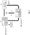
- Fig. 3 shows additional or alternative steps of a method according to an embodiment.
- checking control logic against customer specification of interlocks by using C&E matrices may be performed.
- customer input is given, e.g. in form of a C&E matrix #1.
- control logic - e.g. compliant to IEC 61131-3 - is generated.
- automated reverse engineering may be done by generating C&E matrix #2; this may be compared it to C&E matrix #1 for consistency check.
- feedback is given to an engineer. This person may, then, approve, reject, etc. the identified interlock via a user interface.
- Fig. 4 shows additional or alternative steps of a method according to an embodiment.
- a generic rule is specified by an engineer - e.g. a domain expert, process engineer, or knowledge engineer - using P&ID shapes. This is a basis for checking an interlock specification as described above and/or below.
- an automated translation of the rule into formal language is performed.
- One syntax that may be used looks like this:
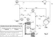
- Fig. 5 shows a visualizing example according to an embodiment.
- a sensor B104 gives a "High Temperature Alarm” as “cause” C.
- this signal is forwarded to the "effect” E, namely to an actuator "Heat Exchanger E104", which is stopped by this rule.
- One syntax that may be used looks like this:
- Fig. 6 shows a further visualizing example according to an embodiment. This example depicts two actuators that are impacted by a rule. The rule looks like this:
Landscapes
- Engineering & Computer Science (AREA)
- Manufacturing & Machinery (AREA)
- Human Computer Interaction (AREA)
- Physics & Mathematics (AREA)
- General Physics & Mathematics (AREA)
- Automation & Control Theory (AREA)
- General Engineering & Computer Science (AREA)
- Quality & Reliability (AREA)
- Computer Networks & Wireless Communication (AREA)
- Signal Processing (AREA)
- Testing And Monitoring For Control Systems (AREA)
Abstract
Description
- The invention relates to the field of methods for industrial processes, particularly for industrial plants and/or processes, for instance in chemical, mechanical, and/or other production and/or handling processes. The invention further relates to a computer-readable storage medium, an artificial neural network, ANN, and to a use.
- For a description of industrial plants and/or processes, in many cases so-called "interlocks" are used. Algorithms may perform those interlock specifications, e.g. by taking plant topology models from process engineers as a basis for their construction. However, in at least some cases, a safety engineer, service personnel and/or other persons whose work is related to these plants and/or processes, may not trust such algorithms, for example in cases when they are run automatically, and may thus fall back to manual interlock specification, which may be laborious and error-prone.
- It is therefore an objective of the invention to provide an improved capability for checking a behaviour of industrial plants and/or processes. This objective is achieved by the subject-matter of the independent claims. Further embodiments are evident from the dependent patent claims and the following description.
- One aspect relates to a method for visualizing a rule of an industrial process or processing system. The method comprises the steps of:
- Providing a topology model of the industrial process or processing system, wherein the industrial process or processing system comprises at least one sensor and at least one actuator;
Attributing the topology model with a rule, wherein the rule comprises a triple
< cause, traversal, effect >,
wherein: - the cause comprises a range of values from the at least one sensor,
- the effect comprises an action performed by the at least one actuator, and
- the traversal comprises a relation between the cause and the effect;
- The industrial process may be an industrial automation application and/or an industrial process, particularly in an industrial plant, for instance in chemical, mechanical, and/or other production and/or handling processes. The rule - or a plurality of rules - may be part of a so-called interlock specification, which describes at least some aspects of the industrial process. Rules may link two or more devices, e.g. based on a functionality on which the devices are interlocked. At least some interlock specifications may comprise rules, which may represent the devices' relations, e.g. their functional and/or other relations. Rules may comprise safety restrictions. For example, a pump may only be started if a valve on its outlet is opened, in order to prevent overpressure.
- Visualizing may be performed on a visual interface of a computing device, e.g. on a display, a screen, a touch-screen, a beamer, and/or the like. The visualizing may comprise generating a visual specification, e.g. of an interlock specification. The visualizing may be implemented as a computer-implemented method.
- The topology model of the industrial process may describe by visual means elements of the process or plants and their connectivity, e.g. pipes, vessels, etc. for carrying fluids and/or media, electric connections, mechanical, logical, and/or other connections. The topology model comprises at least one sensor and one actuator. These devices of the topology model, of course, strongly depend on the kind of process or plant they are used in. Sensors may, e.g., comprise a metering device for pressure, temperature, light, sound, etc., including complex devices, e.g. for distances, flows, chemical analyses and/or for further purpose. Actuators may, e.g., comprise switches, valves, heaters, coolers, mixers, etc. that are configured to make a physical effect.
- For the interlock specification, the topology model is attributed with a rule - or a plurality of rules -, wherein each rule comprises a triple < cause, traversal, effect >. The rule may comprise further entries. The entry "cause" comprises a range of values from the at least one sensor. The range of values may come directly from one or more sensors, or it may be pre-processed and/or a result of linking several sensors. The entry "effect" comprises any action performed by the actuator (or a plurality of them), depending on the type of actuator. The entry "traversal" comprises a relation between the cause and the effect. One or more causes may contribute to one or more effects. One or more causes may be logically (AND, OR, ...) and/or otherwise connected, e.g. via functions. One or more effect may be logically and/or otherwise connected, e.g. via functions.
- Marking the cause, the traversal and/or the effect may, e.g., be implemented by a click and/or another input on one or more sensors, on one or more actuators, on one or more traversal paths of the topology model, and/or by marking a rule (or "line") of the interlock specification. The visualizing of the elements of the rule in the topology model may, e.g., be implemented by highlighting the components impacted, e.g. by colouring the related elements and/or their backgrounds. Additionally or as an alternative, the related rule may be shown, e.g. on the visual interface of a computing device. The visualizing may be accompanied by further actions.
- This may provide an improved capability for accessing a behaviour of industrial plants and/or processes. It may advantageously contribute to a visual interlock specification that provides safety engineers and/or other persons working with the process or plant with visual feedback on algorithmic interlock specifications. As a further result, this method may allow faster engineering of interlocks, may reuse existing domain-specific knowledge, may be less error-prone, and may reduce or avoid costly inconsistencies in specifications, e.g. in an interlock specification and/or other specifications of plants and/or processes.
- In various embodiments, the topology model is attributed with a rule, based on visual means. This may be performed, e.g., by marking a cause and an effect - e.g. by "clicking" on them - and writing and/or visually programming a further relation between the cause and the effect. This further contributes to an intuitive handling of the model.
- In various embodiments, the method further comprises the step of approving or acknowledging the rule, particularly an interlock detected by the rule. This may be done by a safety engineer and/or other personnel responsible for the process or plant. This may advantageously contribute to a higher level of trust in the specification(s).
- In various embodiments, the method further comprises the step of rejecting the rule, particularly an interlock detected by the rule. This may advantageously be part of a fast and intuitive "debugging process" of the process' or plant's specification(s).
- In various embodiments, the method further comprises the step of refining the rule, particularly an interlock, by performing at least one of: adding a further cause; adding a further effect; adding a further traversal; and/or adding a further element to the rule. The further element may, e.g., be a comment, a further output (e.g. an acoustic signal, a message, etc.), and/or a connection e.g. to a database or another interface. Formally spoken, the rule-triple may thus become an n-tuple (with n > 3). This may advantageously contribute to a more intuitive way of engineering the plant.
- The approving, rejecting, and/or refining may be tracked, e.g. by means of a logging journal.
- In various embodiments, the method further comprises the step of generating the topology model of the industrial process from a Piping-and-Instrumentation Diagram, P&ID, of the industrial process. So far, at least some safety engineers may enter instrument references from I/O lists and/or P&IDs by hand and often add free-text annotations. That manual construction may lead to inconsistencies between different artifacts, e.g., misspelled instrument references leading to inconsistent P&ID. As a consequence of the method as described above and/or below, the plant topology information may be derived from P&IDs, thus reducing an error-prone "media-break".
- In various embodiments, the topology model comprises a plurality of rules. This may bring the benefit of being able to deal with complexity. So far, P&IDs, C&E (Cause & Effect) matrices, and/or further means may be used, which may be less intuitive than methods that comprise visualizing steps. The cognitive load of analysing complex P&IDs with thousands of elements and incorporating various safety regulations and customer requirements may also lead to oversights, e.g., missed required interlocks. While C&E matrices are typically thoroughly reviewed, errors or gaps may propagate into the automation system and cause harm to equipment or human workers. Furthermore, expensive clarifications and feedback loops between safety engineer and control engineer may be required. Rule-based engineering approaches using interlock specifications may offer a good compromise between highly optimized plants and reusable plant knowledge in the form of interlocking rules. However, they may suffer due to an insufficiently intuitive user feedback on how a rule was applied and which subset of the plant topology was involved. This may be a reason why at least some safety engineers do not rely on these tools. Hence, the methods as described above and/or below may contribute to improve this situation.
- In various embodiments, the method further comprises the step of applying at least one step of the methods as described above and/or below to each rule of the plurality of rules. By applying these methods, a kind of completeness of checking the plant's behaviour may be achieved. Consequently, this semi-automated method - and also a system that is configured to run this method - may contribute to enable safety engineers to quickly generate C&E matrices improving or assuring correctness via visual feedback. Applying the methods may comprise to feed P&I diagrams by a process engineer for a process plant into a software tool, where a rule engine may process them to generate interlocks based on pre-specified, domain-specific rules. The result may be displayed, for instance, as a visual overlay to the P&I diagram or topology model, which includes marking up the causing equipment, the traversal paths, and the effected equipment. A process engineer may evaluate this visual representation and approve, reject, correct and/or otherwise deal with the generated Cause & Effect relationships. The approval step may be advantage due to a high heterogeneity of at least some industrial plants with many possibilities of assembling the equipment. Furthermore, this may improve the safety engineer's trust to trust in the methods.
- In various embodiments, the method further comprises the step of generating a Cause & Effect, C&E, matrix from the topology model of the industrial process. Since at least some persons trust this representation more than other methods, this advantageously may help to close "media breaks" between several representations used by different engineers.
- In various embodiments, the method further comprises the step of generating a Control Logic according to IEC 61131-3 from the C&E matrix of the industrial process. This advantageously may make at least some parts or aspects of an interlock specification directly applicable to processes or sub-processes of a plant.
- In various embodiments, the method further comprises the step of generating a Piping-and-Instrumentation Diagram, P&ID, from the topology model of the industrial process. This may further contribute to better understand and/or verify the interlock specification and/or the topology model.
- In various embodiments, the method further comprises the step of: If at least two rules relate to the same sensor, checking the related causes for overlapping ranges and/or gaps between their ranges. The "cause" may comprise a range of values from the at least one sensor, which are not necessarily consistent, e.g. by typing and/or by construction errors. This may contribute to reducing such consistency errors.
- In various embodiments, the method further comprises the step of: If at least two rules relate to the same actuator, checking the related effects for intersections. For example, if two power sources drive an electric motor, this method may be able to check if their cooperation is non-destructive. This check may be done rule-based.
- An aspect relates to a non-transitory computer-readable storage medium having a program stored therein, which, when executed on a processor, instructs the processor to perform a method according to any one of the preceding claims.
- An aspect relates to an artificial neural network, ANN, configured to be trained by and/or to perform the method of checking if at least two rules related to the same sensor and/or if at least two rules relate to the same actuator and evaluating the consequences of that. For that, the ANN may be trained with inconsistencies and/or destructive cooperation behaviour, e.g. of actuators and/or their controls. Additionally or as an alternative, a machine learning model may be trained based on the engineer's decisions regarding the rule application.
- The system adds the approved Cause & Effect relationships to a matrix, which can subsequently be fed to control logic generation tools. In parallel, the system trains a machine learning mechanism (e.g., a neural network) using the decisions of the safety engineer. This may refine the rule base and improve the quality of interlock generation in later runs. The solution may lower the potential for errors or oversights, since the tag names of the devices or the equipment may be directly derived from the original P&I diagram without manual intervention. Furthermore, the rule engine may be enabled to process complex topologies and may thus be prevented from suffering from cognitive overload. As existing domain knowledge is encoded into rules, it may be reused with limited effort. Additionally, the safety engineer may retain full control over the process and may add interlocks to the generated C&E matrix manually, including issuing peer-reviews.
- Additionally or alternatively, the system also allows the engineer to visually specify new interlock rules by marking up equipment, drawings paths, and assigning properties of cause, traversal, and/or effect to them.
- An aspect relates to a use of a method as described above and/or below for checking a safety and/or a specification of an industrial process.
- For further clarification, the invention is described by means of embodiments shown in the figures. These embodiments are to be considered as examples only, but not as limiting.
- The drawings depict:
-
Fig. 1 steps of a method according to an embodiment; -
Fig. 2 additional or alternative steps of a method according to an embodiment; -
Fig. 3 additional or alternative steps of a method according to an embodiment; -
Fig. 4 additional or alternative steps of a method according to an embodiment; -
Fig. 5 a visualizing example according to an embodiment; -
Fig. 6 a further visualizing example according to an embodiment. -
Fig. 1 shows steps of a method according to an embodiment. Not all steps shown here need to be performed in every embodiment.Fig. 1 depicts components, e.g. software components, as rectangles and artefacts, e.g. tables and/or other representations that may possibly be stored in a memory as rectangles with bevelled corner.Fig. 1 depicts a process engineer who feeds P&I diagrams into a P&ID Importer, which extracts in a step 1 a topology model out of the P&I diagram. The topology model normalizes the diagram for different types of shapes and naming conventions, and may further strip information not relevant for interlock specification, e.g., manual valve elements, specific equipment properties, or versioning annotations. The Rule Engine processes the topology model in astep 2 by identifying equipment that could be relevant for interlock generation. It applies in astep 3 rules, e.g. in form of pre-specified if-then-rules, from a Rule Base, by checking whether the if-clause occurs in the topology model and if a path can be constructed from a "cause" equipment to an "effect" equipment. For example, if a high/high temperature alarm is specified in a tank ("cause"), a "traversal" on the topology model from the tank to a heat exchanger ("effect") is attempted, and, if successful, the according signal to stop the heat exchanger during runtime could be linked to this cause. Such rules may be encoded, e.g., by domain experts or reverse engineered from former manual specifications. - Then, the Rule Engine passes in a
step 4 the identified interlock elements to the Interlock Topology Visualizer. This component creates a custom view on the topology model that focuses on the elements relevant for the identified interlock and a restricted number of contextual elements in astep 5. It then visually marks up the cause, traversal path, and the effect, for instance by using a transparent - possibly coloured - overlay. A safety engineer responsible for interlock specification gets this visualization displayed, e.g., on a screen in astep 6. The safety engineer can then approve, reject, etc. the identified interlock via a user interface in astep 7, which feeds the information back to the Rule Engine in astep 8. The correction may be carried out by manipulating the cause and effect markers in the visualization as well as adjusting the path topology. - The Rule Engine may train a machine learning model, e.g., an artificial neural network, ANN, that supports the interlock generation algorithms. Based, e.g., on contextual information, the safety engineer's decision and the history of applying a specific rule, the Rule Engine may either refine a rule or adjust the specific mechanisms suggesting the rules for a given topology model in a
step 9.Steps 3 to 9 may be applied repeatedly, until all rules have been applied on the entire topology model. Afterwards, the Rule Engine may generate a C&E matrix in astep 10 that may possibly be extended manually, reviewed later, e.g. by other engineers. In astep 11, the C&E matrix may be imported into control logic generation tools, for instance according to IEC 61131-3. - As a variant, a safety engineer may utilize the Interlock Topology Visualization to specify new interlocking rules visually, e.g. by drawing overlays on the topology model. In another variant - particularly in brownfield scenarios -, existing interlocking control logic in an automation system may be reversed-engineered into a C&E matrix and be compared to a matrix generated by the system. This may aid keeping the specifications consistent and may contribute to detect any undesired violations.
- Hence, a visual overlay or another kind of visualizing generated C&Es on top of customized, streamlined plant topology model cut-out is provided. This delivers a mechanism that allows safety engineers and/or other personnel that run the process interact with rule engine. Furthermore, a machine learning model may be trained with human inputs in the context of interlock specification. For example, the Rule Engine may incorporate engineer decisions as "learnings"; contextual information may be recorded for an interlock/C&E situation, the ML algorithm may be recalibrated, e.g. by adjusting weights in the ANN accordingly. Additionally, reverse engineering IEC 61131 control logic into a C&E matrix and comparing the original C&E matrix against it may be performed. According to the methods described above and/or below, a tool allowing visual specification of new interlock rules by marking up equipment, drawings paths, and assigning cause/traversal/effect properties to them is made available. Besides, an automatic path proposer by calculating the shortest path between specified C&Es may be added. The method shown may lead to faster engineering of interlocks, to a reuse of existing knowledge encoded in rules, is advantageously less error-prone than, e.g., manual and/or "media-breaking" approaches, may contribute to avoid human oversights, and/or may contribute to avoid artefact inconsistencies.
-
Fig. 2 shows additional or alternative steps of a method according to an embodiment. In astep 1, a visual feedback is provided to an engineer by the visualizing tool as described above and/or below. In astep 2, the engineer approves, rejects, etc. the identified interlock via a user interface. This may be done repeatedly. In astep 3, a C&E matrix may be generated from the verified interlock topology. In astep 4, the C&E matrix may be imported into control logic generation tools, for instance according to IEC 61131-3. -
Fig. 3 shows additional or alternative steps of a method according to an embodiment. By this, checking control logic against customer specification of interlocks by using C&E matrices may be performed. In astep 1, customer input is given, e.g. in form of aC&E matrix # 1. In astep 2, control logic - e.g. compliant to IEC 61131-3 - is generated. In astep 3, automated reverse engineering may be done by generatingC&E matrix # 2; this may be compared it toC&E matrix # 1 for consistency check. In astep 4, feedback is given to an engineer. This person may, then, approve, reject, etc. the identified interlock via a user interface. -
Fig. 4 shows additional or alternative steps of a method according to an embodiment. In astep 1, a generic rule is specified by an engineer - e.g. a domain expert, process engineer, or knowledge engineer - using P&ID shapes. This is a basis for checking an interlock specification as described above and/or below. In astep 2, an automated translation of the rule into formal language is performed. One syntax that may be used looks like this:
visualizing the elements of the rule in the topology model.
       Valve.Closed
        -> Valve/Pipe/Reactor-1
        -> Reactor-1\Pipe\Valve-2
       => Valve-2.Close
In the example shown, closing a valve on a pipe feeding a reactor leads to closing another valve on another pipe also feeding the reactor. The character "/" indicates a traversal of the topology model in the direction of the material or logical flow, while the character "\" indicates a traversal of the topology model in the direction opposite to the material or logical flow. The example interlocks all the valves feeding a reactor and causes all of them to close once one of them is closed.In a
In a
       CAUSE: High Temperature Alarm B104
       TRAVERSAL: Information Flow Connection
       EFFECT: Stop Heat Exchanger E104
In the tool, the "cause" C, the "transversal" T or transversal path, and the "effect" E may be highlighted. Furthermore, a window displaying this rule may be shown, and a check-box "Approve / Reject" may be displayed. Then, an engineer may approve or reject the highlighted rule.
       CAUSE: High Level Alarm B114
       TRAVERSAL: All inlets of connected vessel
       EFFECT: Close valve V102, V104
Hence, the sensor "High Level Alarm B114", as "cause" C, makes, as "effect" E, to Close valve V102, V104.
Claims (15)
- A method for visualizing a rule of an industrial process or processing system, the method comprising the steps of:providing a topology model of the industrial process, wherein the industrial process comprises at least one sensor and at least one actuator;attributing the topology model with a rule (R), wherein the rule (R) comprises a triple < cause (C), traversal (T), effect (E) >,
whereinthe cause (C) comprises a range of values from the at least one sensor,the effect (E) comprises an action performed by the at least one actuator, andthe traversal (T) comprises a relation between the cause (C) and the effect (E);marking the cause (C), the traversal (T) and/or the effect (E); andvisualizing the elements of the rule (R) in the topology model. - The method of claim 1,
wherein attributing the topology model with a rule (R) is based on visual means. - The method of claim 1, further comprising the step of:
approving the rule (R) or rejecting the rule (R). - The method of claim 1, further comprising the step of:
refining the rule (R), by performing at least one of:adding a further cause (C);adding a further effect (E);adding a further traversal (T); and/oradding a further element to the rule (R). - The method of claim 1, further comprising the step of:
generating the topology model of the industrial process from a Piping-and-Instrumentation Diagram, P&ID, of the industrial process. - The method of any one of the preceding claims,
wherein the topology model comprises a plurality of rules (R). - The method of claim 6, further comprising the steps of:
applying at least one step of any one of the preceding claims to each rule (R) of the plurality of rules (R). - The method of claim 7, further comprising the step of:
generating a Cause & Effect, C&E, matrix from the topology model of the industrial process. - The method of claim 8, further comprising the step of:
generating a Control Logic according to IEC 61131-3 from the C&E matrix of the industrial process. - The method of claim 6, further comprising the step of:
generating a Piping-and-Instrumentation Diagram, P&ID, from the topology model of the industrial process. - The method of claim 6, further comprising the step of:
if at least two rules (R) relate to the same sensor, checking the related causes (C) for overlapping ranges and/or gaps between their ranges. - The method of claim 6, further comprising the step of:
if at least two rules (R) relate to the same actuator, checking the related effects (E) for intersections. - A non-transitory computer-readable storage medium having a program stored therein, which, when executed on a processor, instructs the processor to perform a method according to any one of the preceding claims.
- An artificial neural network, ANN, configured to be trained by and/or to perform the method of claim 11 or 12.
- Use of a method according to any one of the claims 1 to 12 for checking a safety and/or a specification of an industrial process.
Priority Applications (5)
| Application Number | Priority Date | Filing Date | Title |
|---|---|---|---|
| EP20200904.9A EP3982219A1 (en) | 2020-10-08 | 2020-10-08 | Visual interlock specification for industrial automation |
| CN202180055901.9A CN116097629B (en) | 2020-10-08 | 2021-08-26 | Visual interlocking specifications for industrial automation |
| PCT/EP2021/073654 WO2022073686A1 (en) | 2020-10-08 | 2021-08-26 | Visual interlock specification for industrial automation |
| JP2023512748A JP7612837B2 (en) | 2020-10-08 | 2021-08-26 | Visual Interlocking Specification for Industrial Automation |
| US18/297,107 US20230244212A1 (en) | 2020-10-08 | 2023-04-07 | Visual Interlock Specification for Industrial Automation |
Applications Claiming Priority (1)
| Application Number | Priority Date | Filing Date | Title |
|---|---|---|---|
| EP20200904.9A EP3982219A1 (en) | 2020-10-08 | 2020-10-08 | Visual interlock specification for industrial automation |
Publications (1)
| Publication Number | Publication Date |
|---|---|
| EP3982219A1 true EP3982219A1 (en) | 2022-04-13 |
Family
ID=72811768
Family Applications (1)
| Application Number | Title | Priority Date | Filing Date |
|---|---|---|---|
| EP20200904.9A Pending EP3982219A1 (en) | 2020-10-08 | 2020-10-08 | Visual interlock specification for industrial automation |
Country Status (5)
| Country | Link |
|---|---|
| US (1) | US20230244212A1 (en) |
| EP (1) | EP3982219A1 (en) |
| JP (1) | JP7612837B2 (en) |
| CN (1) | CN116097629B (en) |
| WO (1) | WO2022073686A1 (en) |
Citations (2)
| Publication number | Priority date | Publication date | Assignee | Title |
|---|---|---|---|---|
| US20170205819A1 (en) * | 2016-01-15 | 2017-07-20 | Yokogawa Electric Corporation | Monitoring control system and work support method |
| EP3364261A1 (en) * | 2017-02-15 | 2018-08-22 | ABB Schweiz AG | Generation of partial plant topology data from plant operations data |
Family Cites Families (8)
| Publication number | Priority date | Publication date | Assignee | Title |
|---|---|---|---|---|
| US6993456B2 (en) * | 1999-09-30 | 2006-01-31 | Rockwell Automation Technologies, Inc. | Mechanical-electrical template based method and apparatus |
| JP2002333918A (en) | 2001-05-08 | 2002-11-22 | Mitsubishi Electric Corp | Automatic data generation method and device for monitoring control system and program |
| WO2014058900A1 (en) | 2012-10-08 | 2014-04-17 | Fisher-Rosemount Systems, Inc. | Dynamically reusable classes |
| US10108183B2 (en) | 2014-11-12 | 2018-10-23 | Yokogawa Electric Corporation | Process control system and configuration system |
| JP6747865B2 (en) | 2016-05-18 | 2020-08-26 | 三菱電機株式会社 | Supervisory control device |
| JP6624008B2 (en) | 2016-10-27 | 2019-12-25 | 横河電機株式会社 | Engineering tool cooperation device, engineering tool cooperation method, engineering tool cooperation program and recording medium |
| JP6485537B1 (en) | 2017-12-28 | 2019-03-20 | 横河電機株式会社 | Apparatus, method, and program |
| US11403541B2 (en) * | 2019-02-14 | 2022-08-02 | Rockwell Automation Technologies, Inc. | AI extensions and intelligent model validation for an industrial digital twin |
-
2020
- 2020-10-08 EP EP20200904.9A patent/EP3982219A1/en active Pending
-
2021
- 2021-08-26 WO PCT/EP2021/073654 patent/WO2022073686A1/en not_active Ceased
- 2021-08-26 JP JP2023512748A patent/JP7612837B2/en active Active
- 2021-08-26 CN CN202180055901.9A patent/CN116097629B/en active Active
-
2023
- 2023-04-07 US US18/297,107 patent/US20230244212A1/en active Pending
Patent Citations (2)
| Publication number | Priority date | Publication date | Assignee | Title |
|---|---|---|---|---|
| US20170205819A1 (en) * | 2016-01-15 | 2017-07-20 | Yokogawa Electric Corporation | Monitoring control system and work support method |
| EP3364261A1 (en) * | 2017-02-15 | 2018-08-22 | ABB Schweiz AG | Generation of partial plant topology data from plant operations data |
Non-Patent Citations (1)
| Title |
|---|
| NATHAN LAU ET AL: "Ecological Interface Design in the Nuclear Domain: An Application to the Secondary Subsystems of a Boiling Water Reactor Plant Simulator", IEEE TRANSACTIONS ON NUCLEAR SCIENCE, IEEE SERVICE CENTER, NEW YORK, NY, US, vol. 55, no. 6, 1 December 2008 (2008-12-01), pages 3579 - 3596, XP011240848, ISSN: 0018-9499, DOI: 10.1109/TNS.2008.2005979 * |
Also Published As
| Publication number | Publication date |
|---|---|
| WO2022073686A1 (en) | 2022-04-14 |
| JP7612837B2 (en) | 2025-01-14 |
| CN116097629B (en) | 2025-05-02 |
| CN116097629A (en) | 2023-05-09 |
| US20230244212A1 (en) | 2023-08-03 |
| JP2023538435A (en) | 2023-09-07 |
Similar Documents
| Publication | Publication Date | Title |
|---|---|---|
| Torre et al. | Using models to enable compliance checking against the GDPR: an experience report | |
| Biggs et al. | Integrating Safety and Reliability Analysis into MBSE: overview of the new proposed OMG standard | |
| Torre et al. | Modeling data protection and privacy: application and experience with GDPR | |
| Mensah et al. | Conducting A Comparative Analysis of Medical Negligence Laws in Ghana's Courts Act 1993 (Act 459) and Other African Common Law Countries Concerning Artificial Intelligence Systems | |
| Burggräf et al. | Creation of an expert system for design validation in BIM-based factory design through automatic checking of semantic information | |
| Donvir et al. | The role of generative AI tools in application development: A comprehensive review of current technologies and practices | |
| Bendell et al. | Software Reliability: State of the Art Report 14: 2 | |
| Kaya et al. | Large language models powered system safety assessment: applying STPA and FRAM | |
| Batarseh et al. | Validation of knowledge-based systems: a reassessment of the field | |
| Hu et al. | Leveraging generative AI tools for proactive risk mitigation in design | |
| Malins et al. | SysML activity models for applying ISO 14971 medical device risk and safety management across the system lifecycle | |
| Kluse | A critical analysis of the AIAG-VDA FMEA; Does the newly released AIAG-VDA method offer improvements over the former AIAG method? | |
| Uchitel et al. | Supporting incremental behaviour model elaboration | |
| US20230244212A1 (en) | Visual Interlock Specification for Industrial Automation | |
| Wang | Development of a computer-aided fault tree synthesis methodology for quantitative risk analysis in the chemical process industry | |
| Markaj et al. | Intention-based engineering for process plants | |
| Perkusich et al. | Evaluating the Quality of User Stories: A Comparative Study of Large Language Models and Rule-Based Tool | |
| CN117480455A (en) | Methods for expressing and modeling intent in process plant engineering | |
| Bamil | Vibe Coding: Toward an AI-Native Paradigm for Semantic and Intent-Driven Programming | |
| Sharbaf et al. | Towards automatic generation of formal specifications for UML consistency verification | |
| Pataricza et al. | Lightweight formal analysis of requirements | |
| Rooda et al. | MC/DC test set selection for Synthesis-Based Engineering | |
| Mao et al. | Towards Requirements Engineering for GenAI-Enabled Software: Bridging Responsibility Gaps through Human Oversight Requirements | |
| Thomas et al. | An innovative and automated solution for NERC PRC-027-1 compliance | |
| Ilieva et al. | A Generative AI-Based Framework for Proactive Quality Assurance and Auditing |
Legal Events
| Date | Code | Title | Description |
|---|---|---|---|
| PUAI | Public reference made under article 153(3) epc to a published international application that has entered the european phase |
Free format text: ORIGINAL CODE: 0009012 |
|
| STAA | Information on the status of an ep patent application or granted ep patent |
Free format text: STATUS: THE APPLICATION HAS BEEN PUBLISHED |
|
| AK | Designated contracting states |
Kind code of ref document: A1 Designated state(s): AL AT BE BG CH CY CZ DE DK EE ES FI FR GB GR HR HU IE IS IT LI LT LU LV MC MK MT NL NO PL PT RO RS SE SI SK SM TR |
|
| STAA | Information on the status of an ep patent application or granted ep patent |
Free format text: STATUS: REQUEST FOR EXAMINATION WAS MADE |
|
| 17P | Request for examination filed |
Effective date: 20221010 |
|
| RBV | Designated contracting states (corrected) |
Designated state(s): AL AT BE BG CH CY CZ DE DK EE ES FI FR GB GR HR HU IE IS IT LI LT LU LV MC MK MT NL NO PL PT RO RS SE SI SK SM TR |
|
| STAA | Information on the status of an ep patent application or granted ep patent |
Free format text: STATUS: EXAMINATION IS IN PROGRESS |
|
| 17Q | First examination report despatched |
Effective date: 20241128 |