EP3982190A1 - Light source device, projection apparatus and 3d apparatus comprising same - Google Patents
Light source device, projection apparatus and 3d apparatus comprising same Download PDFInfo
- Publication number
- EP3982190A1 EP3982190A1 EP20835323.5A EP20835323A EP3982190A1 EP 3982190 A1 EP3982190 A1 EP 3982190A1 EP 20835323 A EP20835323 A EP 20835323A EP 3982190 A1 EP3982190 A1 EP 3982190A1
- Authority
- EP
- European Patent Office
- Prior art keywords
- light
- laser
- source device
- unit
- light source
- Prior art date
- Legal status (The legal status is an assumption and is not a legal conclusion. Google has not performed a legal analysis and makes no representation as to the accuracy of the status listed.)
- Granted
Links
Images




Classifications
-
- G—PHYSICS
- G02—OPTICS
- G02B—OPTICAL ELEMENTS, SYSTEMS OR APPARATUS
- G02B30/00—Optical systems or apparatus for producing three-dimensional [3D] effects, e.g. stereoscopic images
- G02B30/20—Optical systems or apparatus for producing three-dimensional [3D] effects, e.g. stereoscopic images by providing first and second parallax images to an observer's left and right eyes
- G02B30/22—Optical systems or apparatus for producing three-dimensional [3D] effects, e.g. stereoscopic images by providing first and second parallax images to an observer's left and right eyes of the stereoscopic type
- G02B30/25—Optical systems or apparatus for producing three-dimensional [3D] effects, e.g. stereoscopic images by providing first and second parallax images to an observer's left and right eyes of the stereoscopic type using polarisation techniques
-
- G—PHYSICS
- G03—PHOTOGRAPHY; CINEMATOGRAPHY; ANALOGOUS TECHNIQUES USING WAVES OTHER THAN OPTICAL WAVES; ELECTROGRAPHY; HOLOGRAPHY
- G03B—APPARATUS OR ARRANGEMENTS FOR TAKING PHOTOGRAPHS OR FOR PROJECTING OR VIEWING THEM; APPARATUS OR ARRANGEMENTS EMPLOYING ANALOGOUS TECHNIQUES USING WAVES OTHER THAN OPTICAL WAVES; ACCESSORIES THEREFOR
- G03B21/00—Projectors or projection-type viewers; Accessories therefor
- G03B21/14—Details
- G03B21/20—Lamp housings
- G03B21/206—Control of light source other than position or intensity
-
- G—PHYSICS
- G02—OPTICS
- G02B—OPTICAL ELEMENTS, SYSTEMS OR APPARATUS
- G02B27/00—Optical systems or apparatus not provided for by any of the groups G02B1/00 - G02B26/00, G02B30/00
- G02B27/09—Beam shaping, e.g. changing the cross-sectional area, not otherwise provided for
- G02B27/0938—Using specific optical elements
- G02B27/0994—Fibers, light pipes
-
- G—PHYSICS
- G02—OPTICS
- G02B—OPTICAL ELEMENTS, SYSTEMS OR APPARATUS
- G02B27/00—Optical systems or apparatus not provided for by any of the groups G02B1/00 - G02B26/00, G02B30/00
- G02B27/10—Beam splitting or combining systems
- G02B27/1006—Beam splitting or combining systems for splitting or combining different wavelengths
- G02B27/102—Beam splitting or combining systems for splitting or combining different wavelengths for generating a colour image from monochromatic image signal sources
- G02B27/104—Beam splitting or combining systems for splitting or combining different wavelengths for generating a colour image from monochromatic image signal sources for use with scanning systems
-
- G—PHYSICS
- G02—OPTICS
- G02B—OPTICAL ELEMENTS, SYSTEMS OR APPARATUS
- G02B27/00—Optical systems or apparatus not provided for by any of the groups G02B1/00 - G02B26/00, G02B30/00
- G02B27/28—Optical systems or apparatus not provided for by any of the groups G02B1/00 - G02B26/00, G02B30/00 for polarising
- G02B27/283—Optical systems or apparatus not provided for by any of the groups G02B1/00 - G02B26/00, G02B30/00 for polarising used for beam splitting or combining
-
- G—PHYSICS
- G02—OPTICS
- G02B—OPTICAL ELEMENTS, SYSTEMS OR APPARATUS
- G02B27/00—Optical systems or apparatus not provided for by any of the groups G02B1/00 - G02B26/00, G02B30/00
- G02B27/48—Laser speckle optics
-
- G—PHYSICS
- G03—PHOTOGRAPHY; CINEMATOGRAPHY; ANALOGOUS TECHNIQUES USING WAVES OTHER THAN OPTICAL WAVES; ELECTROGRAPHY; HOLOGRAPHY
- G03B—APPARATUS OR ARRANGEMENTS FOR TAKING PHOTOGRAPHS OR FOR PROJECTING OR VIEWING THEM; APPARATUS OR ARRANGEMENTS EMPLOYING ANALOGOUS TECHNIQUES USING WAVES OTHER THAN OPTICAL WAVES; ACCESSORIES THEREFOR
- G03B21/00—Projectors or projection-type viewers; Accessories therefor
- G03B21/14—Details
- G03B21/20—Lamp housings
- G03B21/2006—Lamp housings characterised by the light source
- G03B21/2033—LED or laser light sources
-
- G—PHYSICS
- G03—PHOTOGRAPHY; CINEMATOGRAPHY; ANALOGOUS TECHNIQUES USING WAVES OTHER THAN OPTICAL WAVES; ELECTROGRAPHY; HOLOGRAPHY
- G03B—APPARATUS OR ARRANGEMENTS FOR TAKING PHOTOGRAPHS OR FOR PROJECTING OR VIEWING THEM; APPARATUS OR ARRANGEMENTS EMPLOYING ANALOGOUS TECHNIQUES USING WAVES OTHER THAN OPTICAL WAVES; ACCESSORIES THEREFOR
- G03B21/00—Projectors or projection-type viewers; Accessories therefor
- G03B21/14—Details
- G03B21/20—Lamp housings
- G03B21/2006—Lamp housings characterised by the light source
- G03B21/2033—LED or laser light sources
- G03B21/204—LED or laser light sources using secondary light emission, e.g. luminescence or fluorescence
-
- G—PHYSICS
- G03—PHOTOGRAPHY; CINEMATOGRAPHY; ANALOGOUS TECHNIQUES USING WAVES OTHER THAN OPTICAL WAVES; ELECTROGRAPHY; HOLOGRAPHY
- G03B—APPARATUS OR ARRANGEMENTS FOR TAKING PHOTOGRAPHS OR FOR PROJECTING OR VIEWING THEM; APPARATUS OR ARRANGEMENTS EMPLOYING ANALOGOUS TECHNIQUES USING WAVES OTHER THAN OPTICAL WAVES; ACCESSORIES THEREFOR
- G03B21/00—Projectors or projection-type viewers; Accessories therefor
- G03B21/14—Details
- G03B21/20—Lamp housings
- G03B21/2066—Reflectors in illumination beam
-
- G—PHYSICS
- G03—PHOTOGRAPHY; CINEMATOGRAPHY; ANALOGOUS TECHNIQUES USING WAVES OTHER THAN OPTICAL WAVES; ELECTROGRAPHY; HOLOGRAPHY
- G03B—APPARATUS OR ARRANGEMENTS FOR TAKING PHOTOGRAPHS OR FOR PROJECTING OR VIEWING THEM; APPARATUS OR ARRANGEMENTS EMPLOYING ANALOGOUS TECHNIQUES USING WAVES OTHER THAN OPTICAL WAVES; ACCESSORIES THEREFOR
- G03B21/00—Projectors or projection-type viewers; Accessories therefor
- G03B21/14—Details
- G03B21/20—Lamp housings
- G03B21/2073—Polarisers in the lamp house
-
- G—PHYSICS
- G03—PHOTOGRAPHY; CINEMATOGRAPHY; ANALOGOUS TECHNIQUES USING WAVES OTHER THAN OPTICAL WAVES; ELECTROGRAPHY; HOLOGRAPHY
- G03B—APPARATUS OR ARRANGEMENTS FOR TAKING PHOTOGRAPHS OR FOR PROJECTING OR VIEWING THEM; APPARATUS OR ARRANGEMENTS EMPLOYING ANALOGOUS TECHNIQUES USING WAVES OTHER THAN OPTICAL WAVES; ACCESSORIES THEREFOR
- G03B21/00—Projectors or projection-type viewers; Accessories therefor
- G03B21/14—Details
- G03B21/20—Lamp housings
- G03B21/208—Homogenising, shaping of the illumination light
-
- G—PHYSICS
- G02—OPTICS
- G02B—OPTICAL ELEMENTS, SYSTEMS OR APPARATUS
- G02B26/00—Optical devices or arrangements for the control of light using movable or deformable optical elements
- G02B26/08—Optical devices or arrangements for the control of light using movable or deformable optical elements for controlling the direction of light
-
- G—PHYSICS
- G02—OPTICS
- G02B—OPTICAL ELEMENTS, SYSTEMS OR APPARATUS
- G02B27/00—Optical systems or apparatus not provided for by any of the groups G02B1/00 - G02B26/00, G02B30/00
- G02B27/09—Beam shaping, e.g. changing the cross-sectional area, not otherwise provided for
- G02B27/0938—Using specific optical elements
- G02B27/095—Refractive optical elements
- G02B27/0955—Lenses
-
- G—PHYSICS
- G02—OPTICS
- G02B—OPTICAL ELEMENTS, SYSTEMS OR APPARATUS
- G02B27/00—Optical systems or apparatus not provided for by any of the groups G02B1/00 - G02B26/00, G02B30/00
- G02B27/10—Beam splitting or combining systems
- G02B27/14—Beam splitting or combining systems operating by reflection only
- G02B27/141—Beam splitting or combining systems operating by reflection only using dichroic mirrors
Definitions
- the present disclosure relates to the technical field of laser projection, and in particular, to a light source device, a projection apparatus and a 3D apparatus having the same.
- the polarization 3D technology is adopted.
- the main principle is to convert non-polarized light exited from a lens of the projection apparatus into linearly polarized light by using a linear polarization device.
- the linearly polarized light is sequentially converted into left-handed circularly polarized light and right-handed circularly polarized light by using a liquid crystal phase modulation device according to a frame sequence.
- the polarization 3D technology can be classified into: single-optical-path 3D, dual-optical-path 3D, and three-optical-path 3D.
- the dual-optical-path and three-optical-path 3D technologies are the major 3D projection technology types used in theaters due to their higher light efficiency.
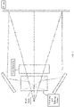
- FIG. 1 is a schematic structural diagram of a diffraction principle of an existing 3D projection technology. Since laser light is a coherent light source with good coherence, the laser light may have a diffraction phenomenon at a prism seam of a polarizing and splitting prism in a 3D projection apparatus.
- the polarizing and splitting prism in the 3D projection apparatus is generally formed by three or four prisms spliced together, and therefore, a prism seam will be formed on the optical axis.
- the prism seam may cause the diffraction effect of incident laser light, resulting in horizontal color fringes in the middle of the screen.
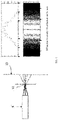
- FIG. 2 is a schematic diagram of a diffraction effect of an existing 3D projection technology.
- the present disclosure provides a light source device, a projection apparatus and a 3D apparatus including the light source device, to solve the problem that diffraction fringes are easily generated in a laser 3D projection apparatus.
- the technical solution adopted by the present disclosure is: a laser generation unit configured to output laser light; a light modification element disposed in a light guide unit or between the light guide unit and a homogenizing unit and configured to cause an angular distribution of the laser light uniform and continuous; the light guide unit, configured to receive the laser light output by the laser generation unit and guide the laser light to the homogenizing unit; and the homogenizing unit, configured to receive the laser light from the light guide unit, and homogenize and output the laser light.
- the present disclosure provides a projection apparatus, including the light source device described above and an opto-mechanical device, the opto-mechanical device includes at least one lens and is configured to receive a homogeneous light from the light source device, process the homogeneous light through the lens, and then output the homogeneous light.
- the present disclosure further provides a 3D apparatus, including the projection apparatus described above; and a polarizing and splitting device including a prism unit and a lens assembly, and is configured to convert light emitted from the projection apparatus into polarized light through the prism unit and the lens assembly, and project the polarized light on a screen.
- a polarizing and splitting device including a prism unit and a lens assembly, and is configured to convert light emitted from the projection apparatus into polarized light through the prism unit and the lens assembly, and project the polarized light on a screen.
- a light source device includes a laser generation unit, a light modification element, a light guide unit, and a homogenizing unit.
- the light modification element has the effects of reducing the spatial coherence of the laser light and making an angular distribution of the laser light uniform and continuous. Therefore, by changing the position of the light modification element inside the light source device, the diffraction phenomenon produced by the laser light at the prism seam of the polarizing and splitting prism in the 3D apparatus is weakened, which greatly improves the viewing effect for users.
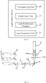
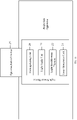
- FIG. 3 is a schematic structural diagram of a light source device according to the present disclosure.
- the light source device includes a laser generation unit 21, configured to output laser light; a light modification element 22, configured to cause an angular distribution of the laser light uniform and continuous; a light guide unit 23, configured to receive the laser light output by the laser generation unit and guide the laser light to a homogenizing unit; and the homogenizing unit 24, configured to receive the laser light from the light guide unit 23, and homogenize and output the laser light.
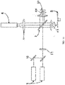
- FIG. 4 is a schematic structural diagram of Embodiment 1 of a light source device according to the present disclosure.
- FIG. 12 is a schematic structural diagram of a 3D apparatus according to the present disclosure.
- the laser generation unit 21 includes a plurality of primary color lasers 1.
- the primary color lasers 1 include a red laser for emitting red laser light, a green laser for emitting green laser light, and a blue laser for emitting blue laser. Laser light emitted from the plurality of primary color lasers is combined by a light combining lens 10 and then output to the light guide unit 23.
- the light guide unit 23 includes a first focusing lens 11, a scattering wheel 7, a first relay lens 61, a second relay lens 62, a light guide element 2, a third relay lens 63, and a fourth relay lens 64.
- the light modification element 22 is disposed between the third relay lens 63 and the fourth relay lens 64.
- the first focusing lens 11 is configured to gather the laser light guided from the light combining lens 10. Light scattered by the scattering wheel 7 sequentially passes through the first relay lens 61, the second relay lens 62, the light guide element 2, the third relay lens 63, the light modification element 22, and the fourth relay lens 64, then enters the homogenizing unit 24 through a light incident surface of the homogenizing unit 24, and is output after being homogenized.
- the light modification element 22 is a scattering sheet 31, and the homogenizing unit 24 is a light bar 4.
- the light modification element 22 may also be other types of elements, such as a fly-eye lens assembly 32, which is not specifically limited herein, as long as it can modify the optical angle of the laser light to make the angular distribution uniform and continuous.
- the laser light emitted from the third relay lens 63 has a continuous planar distribution, while the angular distribution is non-uniform and discontinuous.
- the beam is incident on the scattering sheet 31, and is output after the angle of the beam is expanded by the scattering sheet 31.
- the scattering sheet 31 mainly achieves the effect of improving the angular distribution of the laser.
- FIG. 5 is a schematic diagram of a principle of eliminating diffraction fringes according to the present disclosure. Since the light bar 4 homogenizes the beam without changing the angle of the beam, light emitted from each point on an exit surface of the light bar 4 also has a larger angle as compared with the case without the scattering sheet 31. Therefore, when the laser light passes through the opto-mechanical device, there will be more light at different angles irradiated on a seam formed between prisms of the polarizing and splitting device 26.
- This embodiment can use a hybrid light source consisting of the laser generation unit 21 and an LED light source.
- the embodiments below are also applicable to the hybrid light source consisting of the laser generation unit 21 and the LED light source. Details are not repeated herein.
- FIG. 6 is a schematic structural diagram of Embodiment 2 of a light source device according to the present disclosure.
- FIG. 12 is a schematic structural diagram of a 3D apparatus according to the present disclosure.
- the light source device in this embodiment is different from the Embodiment 1 in further including a fluorescence generation unit.
- the fluorescence generation unit includes a laser 9 configured to generate laser light to excite fluorescence, a dichroic filter 10, a fluorescent wheel 8, a collection lens assembly 65, and a second focusing lens 67.
- the dichroic filter 10 reflects laser light to be irradiated on the fluorescent wheel 8.
- the fluorescent wheel 8 absorbs the laser light and generates fluorescence, which is transferred through the collection lens assembly 65, the dichroic filter 10, and the second focusing lens 67 to the light guide element 2, passes through the light guide element 2, and is combined with laser light to output a hybrid beam.
- a scattering sheet 31 with a particular angle is disposed between the third relay lens 63 and the fourth relay lens 64 of the light guide unit 23.
- the laser light has a continuous planar distribution but a discontinuous angular distribution.
- the hybrid beam is incident on the scattering sheet 31 through the third relay lens 63, and is output after the angle is expanded by the scattering sheet 31.
- the scattering sheet 31 mainly achieves an effect of improving the angular distribution of the laser light, while hardly changing an angular distribution of the fluorescence.
- the laser light in each scattered hybrid beam is gathered by the fourth relay lens 64 and then enters the light bar 4, the laser light in the small hybrid beams which are originally separated from each other spatially intersect each other since the divergence angles are expanded by the scattering sheet 31.
- Each laser light generates a relatively large light spot on an entry surface of the light bar 4, and the light spots overlap with each other, so that each point on the entry surface of the light bar 4 receives light from a larger angle range compared with the case without the scattering sheet 31.
- FIG. 5 is a schematic diagram of a principle of eliminating diffraction fringes according to the present disclosure.
- the light bar 4 homogenizes the beam without changing the angle of the beam, light emitted from each point on a light output end of the light bar 4 also has a larger angle as compared with the case without the scattering sheet 31. Therefore, when the laser light passes through the opto-mechanical device 25, there will be more light at different angles irradiated on a seam formed between prisms of the polarizing and splitting device 26. After beams at different incident angles pass through the prism seam 12, generated diffraction fringes spatially overlap with each other, so that the overall resolution of the fringes on the screen 13 is reduced. By adjusting the scattering angle and scattering form of the scattering sheet 31, the resolution of the fringes can be reduced to a level that is unrecognizable to human eyes.
- FIG. 7 is a schematic structural diagram of Embodiment 3 of a light source device according to the present disclosure.
- FIG. 12 is a schematic structural diagram of a 3D apparatus according to the present disclosure.
- This embodiment is different from Embodiment 2 in that, a fly-eye lens assembly 32 is used in this embodiment to replace the scattering sheet 31. Both the fly-eye lens assembly 32 and the scattering sheet 31 have the effect of widening the angle of emission of the fine beam.
- the first row of lenses in the first row in the fly-eye lens assembly 32 splits the entire hybrid beam into multiple fine beams, the second row of lenses located at the focal point of the first row of lenses images each fine hybrid beam in the same area, and the hybrid beams are superimposed on each other to improve the uniformity of the laser light angle.
- FIG. 5 is a schematic diagram of a principle of eliminating diffraction fringes according to the present disclosure. Light emitted from each point at a light output end of the light bar 4 also has a larger angle as compared with the case without the fly-eye lens assembly 32.
- a light modification element 22 may also be added in front of the light bar 4.
- the light modification element 22 herein may be a fly-eye lens assembly 32 or a scattering sheet 31, to further improve the angular distribution of the laser light, expand the angle of the laser light, and enhance the homogenizing effect of the light bar 4, thereby weakening the diffraction fringe phenomenon of the laser light on the screen 13.
- FIG. 8 is a schematic structural diagram of Embodiment 4 of a light source device according to the present disclosure.
- FIG. 12 is a schematic structural diagram of a 3D apparatus according to the present disclosure.
- This embodiment is different from Embodiment 3 in that, the fly-eye lens assembly 32 is located between the first relay lens 61 and the second relay lens 62.
- the diffusion wheel 7 and the first focusing lens 11 are omitted.
- the first relay lens 61 which is originally an aspheric lens, is replaced by a spherical lens with a small curvature to collimate pure laser light, thereby reducing the manufacturing costs and difficulty of the light source.
- the fly-eye lens assembly 32 is moved to a pure laser optical path, so that the fly-eye lens assembly 32 in the light guide unit 23 only improves the angular distribution of pure laser light that generates diffraction fringes, thereby avoiding influence on fluorescence, and the efficiency of the fluorescence entering the light bar 4 is not affected during diffraction fringe elimination.
- the fly-eye lens assembly 32 in Embodiment 4 achieves the same effect as the fly-eye lens assembly 32 in Embodiment 3, and reduces the spatial coherence of laser light.
- FIG. 5 is a schematic diagram of a principle of eliminating diffraction fringes according to the present disclosure.
- FIG. 9 is a schematic structural diagram of Embodiment 5 of a light source device according to the present disclosure.
- FIG. 12 is a schematic structural diagram of a 3D apparatus according to the present disclosure. This embodiment is different from Embodiment 4 in that, on the basis of Embodiment 4, a scattering sheet 31 is disposed in front of the light bar 4 of the homogenizing unit 24. Such an arrangement alleviates the problem that the laser light from the laser generation unit 21 is only homogenized by the fly-eye lens assembly 32 and has a poor angular distribution.
- FIG. 5 is a schematic diagram of a principle of eliminating diffraction fringes according to the present disclosure.
- the angular distribution of the laser light is further improved, the angle of the laser light is expanded, and the homogenizing effect of the projection apparatus light bar 4 is enhanced, thereby weakening the diffraction fringe phenomenon of the laser light on the screen 13.
- FIG. 10 is a schematic structural diagram of Embodiment 6 of a light source device according to the present disclosure.
- FIG. 12 is a schematic structural diagram of a 3D apparatus according to the present disclosure.
- the laser generation unit 21 in this embodiment includes a plurality of primary color lasers 1.
- the primary color lasers 1 include a red laser for emitting red laser light and a blue laser for emitting blue laser light. Laser light emitted from the plurality of primary color lasers is combined by the light combining lens 10 and then transmitted to the light guide unit 23.
- the light guide unit 23 includes a first focusing lens 11, a light guide element 2, a second focusing lens 67, and a collection lens assembly 66.
- the fluorescence generation unit includes a fluorescent wheel 8 and a collection lens assembly 65.
- the light guide unit 23 transfers the hybrid beam to the homogenizing unit 24. In this case, the laser generation unit 21 not only generates laser light for the laser generation unit but also generates laser light for the fluorescence generation unit.
- the light modification element 22 is a scattering sheet diffuse reflective sheet 33, which is disposed on a light propagation path of the collection lens assembly 66 of the light guide unit 23.
- the homogenizing unit 24 is a light bar 4.
- the light guide element 2 is a regional film.
- Laser light emitted from the primary color lasers 1 is gathered by the light combining lens 10 and the first focusing lens 11, and then transmitted to the light guide element 2 formed by the regional film.
- a central region of the regional film allows one type of laser light to pass and reflects another type of laser light. For example, the central region allows blue laser light to pass and reflects red laser light.
- a peripheral region reflects blue laser light and allows yellow fluorescence to pass.
- Laser light reflected by the regional film is transferred to the fluorescent wheel 8.
- the entire phosphor section on the fluorescent wheel 8 is a yellow phosphor section. Therefore, fluorescence generated by the fluorescent wheel 8 is yellow fluorescence, so that the yellow fluorescence passes through the peripheral region of the regional film. Red laser light is guided to the yellow phosphor section through the regional film.
- the wavelength of the red laser light is not converted, but the laser light will be dispersed, and the angular distribution will become continuous. Therefore, the red laser light will also pass through the peripheral region of the regional film.
- Laser light passing through the center of the regional film is transmitted to the diffuse reflective sheet 33 through the collection lens assembly 66.
- the scattering sheet 31 and the fly-eye lens assembly 32, the diffuse reflective sheet 33 can also achieve the effects of expanding the angle of the laser light and reducing the spatial coherence.
- Laser light reflected by the diffuse reflective sheet 33 is transmitted through the collection lens assembly 66 again to the regional film, to be combined with the fluorescence to form a hybrid beam, which is transferred to the second focusing lens 67 and transmitted to the light incident end of the light bar 4.
- FIG. 5 is a schematic diagram of a principle of eliminating diffraction fringes according to the present disclosure.
- Light emitted from each point at the light output end of the light bar 4 has a larger angle. Therefore, after the laser light passes through the opto-mechanical device 25, light from more different angles will be irradiated on the seam 12 formed between the prisms of the polarizing and splitting device 26. After beams at different incident angles pass through the prism seam 12, generated diffraction fringes spatially overlap with each other, so that the overall resolution of fringes on the screen 13 is reduced.
- the positions and optical parameters of the diffuse reflective sheet 33 and the light guide element 2 are adjusted, so that focal spots fill the entry of the light bar 4 as much as possible, thereby obtaining an optimal diffraction fringe elimination effect.
- the element type and arrangement position of the light modification element 22 can be selected according to specific requirements, and are not limited to the situation described in the embodiments of the present disclosure.
- FIG. 11 is a schematic structural diagram of a projection apparatus according to the present disclosure.
- the projection apparatus includes a light source device described in any of the foregoing embodiments, and an opto-mechanical device 25.
- the opto-mechanical device 25 includes at least one lens and is configured to receive a homogeneous light from the light source device, process the homogeneous light through the lens, and then output the beam.
- Other components and functions of the opto-mechanical device 25 and the projection apparatus are the same as those in the related art, and details are not described herein again.
- FIG. 12 is a schematic structural diagram of a 3D apparatus according to the present disclosure.
- the 3D apparatus includes the projection apparatus described above and a polarizing and splitting device 26.
- the polarizing and splitting device 26 includes a prism unit and a lens assembly, and is configured to convert a beam emitted from the projection apparatus into polarized light through the prism unit and the lens assembly, and project the polarized light on a screen.
- Other components and functions of the polarizing and splitting device 26 and the 3D apparatus are the same as those in the related art, and details are not described herein again.
- the light modification element has the effects of reducing the spatial coherence of the laser light and making an angular distribution of the laser light uniform and continuous, so that the diffraction phenomenon produced by the laser light, which is emitted from the light source device, irradiated on the prism seam of the polarizing and splitting prism in the 3D apparatus is weakened, which greatly improves the viewing effect for users.
Landscapes
- Physics & Mathematics (AREA)
- General Physics & Mathematics (AREA)
- Optics & Photonics (AREA)
- Engineering & Computer Science (AREA)
- Multimedia (AREA)
- Projection Apparatus (AREA)
Abstract
Description
- The present disclosure relates to the technical field of laser projection, and in particular, to a light source device, a projection apparatus and a 3D apparatus having the same.
- In a 3D projection apparatus using laser light as a light source, the polarization 3D technology is adopted. The main principle is to convert non-polarized light exited from a lens of the projection apparatus into linearly polarized light by using a linear polarization device. The linearly polarized light is sequentially converted into left-handed circularly polarized light and right-handed circularly polarized light by using a liquid crystal phase modulation device according to a frame sequence. Based on the types of linear polarization device, the polarization 3D technology can be classified into: single-optical-path 3D, dual-optical-path 3D, and three-optical-path 3D. The dual-optical-path and three-optical-path 3D technologies are the major 3D projection technology types used in theaters due to their higher light efficiency.
-
FIG. 1 is a schematic structural diagram of a diffraction principle of an existing 3D projection technology. Since laser light is a coherent light source with good coherence, the laser light may have a diffraction phenomenon at a prism seam of a polarizing and splitting prism in a 3D projection apparatus. The polarizing and splitting prism in the 3D projection apparatus is generally formed by three or four prisms spliced together, and therefore, a prism seam will be formed on the optical axis. Depending on the accuracy of the production process, the prism seam may cause the diffraction effect of incident laser light, resulting in horizontal color fringes in the middle of the screen. Laser light emitted from the light source is further homogenized by a light bar of the projection apparatus, but the continuity of laser angular distribution per unit area is not significantly improved. The angular distribution of the beam is no longer changed by the relay lens, prism, digital mirror device (DMD), lens, or the like on the optical path of the projection apparatus. Therefore, light emitted from the lens is light with a discontinuous angular distribution at a light output end of the light bar of the projection apparatus.FIG. 2 is a schematic diagram of a diffraction effect of an existing 3D projection technology. When a 3D movie is played, only a small part in the middle of the whole beam is illuminated on the diffraction obstacle (prism seam) of the three-optical-path 3D projection apparatus, thus forming clear diffraction fringes on the screen to affect the projection viewing effect. At present, the intensity of color fringes can be reduced by special treatment on the prism edge and optimization of the prism gluing and splicing process. However, conventional methods may bring high requirements on the production technology of the projection apparatus, which increases the production and usage costs of the projection apparatus. - The present disclosure provides a light source device, a projection apparatus and a 3D apparatus including the light source device, to solve the problem that diffraction fringes are easily generated in a laser 3D projection apparatus.
- To solve the above technical problems, the technical solution adopted by the present disclosure is: a laser generation unit configured to output laser light; a light modification element disposed in a light guide unit or between the light guide unit and a homogenizing unit and configured to cause an angular distribution of the laser light uniform and continuous; the light guide unit, configured to receive the laser light output by the laser generation unit and guide the laser light to the homogenizing unit; and the homogenizing unit, configured to receive the laser light from the light guide unit, and homogenize and output the laser light.
- The present disclosure provides a projection apparatus, including the light source device described above and an opto-mechanical device, the opto-mechanical device includes at least one lens and is configured to receive a homogeneous light from the light source device, process the homogeneous light through the lens, and then output the homogeneous light.
- The present disclosure further provides a 3D apparatus, including the projection apparatus described above; and a polarizing and splitting device including a prism unit and a lens assembly, and is configured to convert light emitted from the projection apparatus into polarized light through the prism unit and the lens assembly, and project the polarized light on a screen.
- The present disclosure has the following beneficial effects: a light source device includes a laser generation unit, a light modification element, a light guide unit, and a homogenizing unit. The light modification element has the effects of reducing the spatial coherence of the laser light and making an angular distribution of the laser light uniform and continuous. Therefore, by changing the position of the light modification element inside the light source device, the diffraction phenomenon produced by the laser light at the prism seam of the polarizing and splitting prism in the 3D apparatus is weakened, which greatly improves the viewing effect for users.
-
-
FIG. 1 is a schematic structural diagram of a diffraction principle of an existing 3D projection technology; -
FIG. 2 s a schematic diagram of a diffraction effect of an existing 3D projection technology; -
FIG. 3 is a schematic structural diagram of a light source device according to the present disclosure; -
FIG. 4 is a schematic structural diagram of Embodiment 1 of a light source device according to the present disclosure; -
FIG. 5 is a schematic diagram of a principle of eliminating diffraction fringes according to the present disclosure; -
FIG. 6 is a schematic structural diagram of Embodiment 2 of a light source device according to the present disclosure; -
FIG. 7 is a schematic structural diagram of Embodiment 3 of a light source device according to the present disclosure; -
FIG. 8 is a schematic structural diagram ofEmbodiment 4 of a light source device according to the present disclosure; -
FIG. 9 is a schematic structural diagram of Embodiment 5 of a light source device according to the present disclosure; -
FIG. 10 is a schematic structural diagram of Embodiment 6 of a light source device according to the present disclosure; -
FIG. 11 is a schematic structural diagram of a projection apparatus according to the present disclosure; and -
FIG. 12 is a schematic structural diagram of a 3D apparatus according to the present disclosure. - The present disclosure will be described in detail below in conjunction with the accompanying drawings and embodiments.
-
FIG. 3 is a schematic structural diagram of a light source device according to the present disclosure. The light source device includes alaser generation unit 21, configured to output laser light; alight modification element 22, configured to cause an angular distribution of the laser light uniform and continuous; alight guide unit 23, configured to receive the laser light output by the laser generation unit and guide the laser light to a homogenizing unit; and thehomogenizing unit 24, configured to receive the laser light from thelight guide unit 23, and homogenize and output the laser light. -
FIG. 4 is a schematic structural diagram of Embodiment 1 of a light source device according to the present disclosure.FIG. 12 is a schematic structural diagram of a 3D apparatus according to the present disclosure. Thelaser generation unit 21 includes a plurality of primary color lasers 1. The primary color lasers 1 include a red laser for emitting red laser light, a green laser for emitting green laser light, and a blue laser for emitting blue laser. Laser light emitted from the plurality of primary color lasers is combined by alight combining lens 10 and then output to thelight guide unit 23. Thelight guide unit 23 includes a first focusinglens 11, a scattering wheel 7, afirst relay lens 61, asecond relay lens 62, a light guide element 2, athird relay lens 63, and afourth relay lens 64. Thelight modification element 22 is disposed between thethird relay lens 63 and thefourth relay lens 64. The first focusinglens 11 is configured to gather the laser light guided from thelight combining lens 10. Light scattered by the scattering wheel 7 sequentially passes through thefirst relay lens 61, thesecond relay lens 62, the light guide element 2, thethird relay lens 63, thelight modification element 22, and thefourth relay lens 64, then enters thehomogenizing unit 24 through a light incident surface of thehomogenizing unit 24, and is output after being homogenized. - In this embodiment, the
light modification element 22 is ascattering sheet 31, and thehomogenizing unit 24 is alight bar 4. In other embodiments, thelight modification element 22 may also be other types of elements, such as a fly-eye lens assembly 32, which is not specifically limited herein, as long as it can modify the optical angle of the laser light to make the angular distribution uniform and continuous. - The laser light emitted from the
third relay lens 63 has a continuous planar distribution, while the angular distribution is non-uniform and discontinuous. The beam is incident on thescattering sheet 31, and is output after the angle of the beam is expanded by thescattering sheet 31. Thescattering sheet 31 mainly achieves the effect of improving the angular distribution of the laser. When each scattered beam is gathered by thefourth relay lens 64 and then enters thelight bar 4, the small beams which are originally separated from each other spatially intersect each other because the divergence angles thereof are expanded by thescattering sheet 31. Each laser light generates a relatively large light spot on an entry surface of thelight bar 4, and the light spots overlap with each other, so that each point on the entry surface of thelight bar 4 receives light from a larger angle range compared with the case without thescattering sheet 31.FIG. 5 is a schematic diagram of a principle of eliminating diffraction fringes according to the present disclosure. Since thelight bar 4 homogenizes the beam without changing the angle of the beam, light emitted from each point on an exit surface of thelight bar 4 also has a larger angle as compared with the case without thescattering sheet 31. Therefore, when the laser light passes through the opto-mechanical device, there will be more light at different angles irradiated on a seam formed between prisms of the polarizing and splittingdevice 26. After beams at different incident angles pass through theprism seam 12, generated diffraction fringes spatially overlap with each other, so that the overall resolution of the fringes on ascreen 13 is reduced. By adjusting the scattering angle and scattering form of thescattering sheet 31, the resolution of the fringes can be reduced to a level that is unrecognizable to human eyes. - This embodiment can use a hybrid light source consisting of the
laser generation unit 21 and an LED light source. The embodiments below are also applicable to the hybrid light source consisting of thelaser generation unit 21 and the LED light source. Details are not repeated herein. -
FIG. 6 is a schematic structural diagram of Embodiment 2 of a light source device according to the present disclosure.FIG. 12 is a schematic structural diagram of a 3D apparatus according to the present disclosure. The light source device in this embodiment is different from the Embodiment 1 in further including a fluorescence generation unit. The fluorescence generation unit includes alaser 9 configured to generate laser light to excite fluorescence, adichroic filter 10, afluorescent wheel 8, acollection lens assembly 65, and a second focusinglens 67. Thedichroic filter 10 reflects laser light to be irradiated on thefluorescent wheel 8. Thefluorescent wheel 8 absorbs the laser light and generates fluorescence, which is transferred through thecollection lens assembly 65, thedichroic filter 10, and the second focusinglens 67 to the light guide element 2, passes through the light guide element 2, and is combined with laser light to output a hybrid beam. Ascattering sheet 31 with a particular angle is disposed between thethird relay lens 63 and thefourth relay lens 64 of thelight guide unit 23. In the hybrid beam emitted from the light guide element 2, the laser light has a continuous planar distribution but a discontinuous angular distribution. The hybrid beam is incident on thescattering sheet 31 through thethird relay lens 63, and is output after the angle is expanded by thescattering sheet 31. Thescattering sheet 31 mainly achieves an effect of improving the angular distribution of the laser light, while hardly changing an angular distribution of the fluorescence. When the laser light in each scattered hybrid beam is gathered by thefourth relay lens 64 and then enters thelight bar 4, the laser light in the small hybrid beams which are originally separated from each other spatially intersect each other since the divergence angles are expanded by thescattering sheet 31. Each laser light generates a relatively large light spot on an entry surface of thelight bar 4, and the light spots overlap with each other, so that each point on the entry surface of thelight bar 4 receives light from a larger angle range compared with the case without thescattering sheet 31.FIG. 5 is a schematic diagram of a principle of eliminating diffraction fringes according to the present disclosure. Since thelight bar 4 homogenizes the beam without changing the angle of the beam, light emitted from each point on a light output end of thelight bar 4 also has a larger angle as compared with the case without thescattering sheet 31. Therefore, when the laser light passes through the opto-mechanical device 25, there will be more light at different angles irradiated on a seam formed between prisms of the polarizing andsplitting device 26. After beams at different incident angles pass through theprism seam 12, generated diffraction fringes spatially overlap with each other, so that the overall resolution of the fringes on thescreen 13 is reduced. By adjusting the scattering angle and scattering form of thescattering sheet 31, the resolution of the fringes can be reduced to a level that is unrecognizable to human eyes. -
FIG. 7 is a schematic structural diagram of Embodiment 3 of a light source device according to the present disclosure.FIG. 12 is a schematic structural diagram of a 3D apparatus according to the present disclosure. This embodiment is different from Embodiment 2 in that, a fly-eye lens assembly 32 is used in this embodiment to replace thescattering sheet 31. Both the fly-eye lens assembly 32 and thescattering sheet 31 have the effect of widening the angle of emission of the fine beam. The first row of lenses in the first row in the fly-eye lens assembly 32 splits the entire hybrid beam into multiple fine beams, the second row of lenses located at the focal point of the first row of lenses images each fine hybrid beam in the same area, and the hybrid beams are superimposed on each other to improve the uniformity of the laser light angle. - All laser light in the hybrid beam emitted from the light guide element 2 will be completely imaged on the
light bar 4 after passing through the fly-eye lens assembly 32 and thefourth relay lens 64. That is, each small region on thelight bar 4 will receive a small part of the laser light in the whole hybrid beam. The fly-eye lens assembly 32 achieves the same effect as thescattering sheet 31 in Embodiment 2, and reduces the spatial coherence of laser.FIG. 5 is a schematic diagram of a principle of eliminating diffraction fringes according to the present disclosure. Light emitted from each point at a light output end of thelight bar 4 also has a larger angle as compared with the case without the fly-eye lens assembly 32. Therefore, after the laser light passes through the opto-mechanical device 25, light from more different angles will be irradiated on the seam formed between the prisms of the polarizing andsplitting device 26. After beams at different incident angles pass through theprism seam 12, generated diffraction fringes spatially overlap with each other, so that the overall resolution of fringes on thescreen 13 is reduced. The positions and optical parameters of the fly-eye lens assembly 32 and thefourth relay lens 64 are adjusted, so that focal spots fill the light incident end of thelight bar 4 as much as possible, thereby obtaining an optimal diffraction fringe elimination effect. Moreover, in Embodiment 3, alight modification element 22 may also be added in front of thelight bar 4. Thelight modification element 22 herein may be a fly-eye lens assembly 32 or ascattering sheet 31, to further improve the angular distribution of the laser light, expand the angle of the laser light, and enhance the homogenizing effect of thelight bar 4, thereby weakening the diffraction fringe phenomenon of the laser light on thescreen 13. -
FIG. 8 is a schematic structural diagram ofEmbodiment 4 of a light source device according to the present disclosure.FIG. 12 is a schematic structural diagram of a 3D apparatus according to the present disclosure. This embodiment is different from Embodiment 3 in that, the fly-eye lens assembly 32 is located between thefirst relay lens 61 and thesecond relay lens 62. The diffusion wheel 7 and the first focusinglens 11 are omitted. Thefirst relay lens 61, which is originally an aspheric lens, is replaced by a spherical lens with a small curvature to collimate pure laser light, thereby reducing the manufacturing costs and difficulty of the light source. In other words, the fly-eye lens assembly 32 is moved to a pure laser optical path, so that the fly-eye lens assembly 32 in thelight guide unit 23 only improves the angular distribution of pure laser light that generates diffraction fringes, thereby avoiding influence on fluorescence, and the efficiency of the fluorescence entering thelight bar 4 is not affected during diffraction fringe elimination. The fly-eye lens assembly 32 inEmbodiment 4 achieves the same effect as the fly-eye lens assembly 32 in Embodiment 3, and reduces the spatial coherence of laser light.FIG. 5 is a schematic diagram of a principle of eliminating diffraction fringes according to the present disclosure. Light emitted from each point at a light output end of thelight bar 4 also has a larger angle as compared with the case without the fly-eye lens assembly 32. Therefore, after the laser light passes through the opto-mechanical device 25, light from more different angles will be irradiated on the seam formed between the prisms of the polarizing andsplitting device 26. After beams at different incident angles pass through theprism seam 12, generated diffraction fringes spatially overlap with each other, so that the overall resolution of fringes on thescreen 13 is reduced. The positions and optical parameters of the fly-eye lens assembly 32 and thesecond relay lens 62 are adjusted, so that focal spots fill the entry of thelight bar 4 as much as possible, thereby obtaining an optimal diffraction fringe elimination effect. -
FIG. 9 is a schematic structural diagram of Embodiment 5 of a light source device according to the present disclosure.FIG. 12 is a schematic structural diagram of a 3D apparatus according to the present disclosure. This embodiment is different fromEmbodiment 4 in that, on the basis ofEmbodiment 4, ascattering sheet 31 is disposed in front of thelight bar 4 of thehomogenizing unit 24. Such an arrangement alleviates the problem that the laser light from thelaser generation unit 21 is only homogenized by the fly-eye lens assembly 32 and has a poor angular distribution.FIG. 5 is a schematic diagram of a principle of eliminating diffraction fringes according to the present disclosure. By adding thescattering sheet 31 in front of thelight bar 4, the angular distribution of the laser light is further improved, the angle of the laser light is expanded, and the homogenizing effect of the projection apparatuslight bar 4 is enhanced, thereby weakening the diffraction fringe phenomenon of the laser light on thescreen 13. -
FIG. 10 is a schematic structural diagram of Embodiment 6 of a light source device according to the present disclosure.FIG. 12 is a schematic structural diagram of a 3D apparatus according to the present disclosure. Thelaser generation unit 21 in this embodiment includes a plurality of primary color lasers 1. The primary color lasers 1 include a red laser for emitting red laser light and a blue laser for emitting blue laser light. Laser light emitted from the plurality of primary color lasers is combined by thelight combining lens 10 and then transmitted to thelight guide unit 23. Thelight guide unit 23 includes a first focusinglens 11, a light guide element 2, a second focusinglens 67, and acollection lens assembly 66. The fluorescence generation unit includes afluorescent wheel 8 and acollection lens assembly 65. Thelight guide unit 23 transfers the hybrid beam to thehomogenizing unit 24. In this case, thelaser generation unit 21 not only generates laser light for the laser generation unit but also generates laser light for the fluorescence generation unit. - In this embodiment, the
light modification element 22 is a scattering sheet diffusereflective sheet 33, which is disposed on a light propagation path of thecollection lens assembly 66 of thelight guide unit 23. Thehomogenizing unit 24 is alight bar 4. The light guide element 2 is a regional film. - Laser light emitted from the primary color lasers 1 is gathered by the
light combining lens 10 and the first focusinglens 11, and then transmitted to the light guide element 2 formed by the regional film. A central region of the regional film allows one type of laser light to pass and reflects another type of laser light. For example, the central region allows blue laser light to pass and reflects red laser light. A peripheral region reflects blue laser light and allows yellow fluorescence to pass. Laser light reflected by the regional film is transferred to thefluorescent wheel 8. The entire phosphor section on thefluorescent wheel 8 is a yellow phosphor section. Therefore, fluorescence generated by thefluorescent wheel 8 is yellow fluorescence, so that the yellow fluorescence passes through the peripheral region of the regional film. Red laser light is guided to the yellow phosphor section through the regional film. The wavelength of the red laser light is not converted, but the laser light will be dispersed, and the angular distribution will become continuous. Therefore, the red laser light will also pass through the peripheral region of the regional film. Laser light passing through the center of the regional film is transmitted to the diffusereflective sheet 33 through thecollection lens assembly 66. Thescattering sheet 31 and the fly-eye lens assembly 32, the diffusereflective sheet 33 can also achieve the effects of expanding the angle of the laser light and reducing the spatial coherence. Laser light reflected by the diffusereflective sheet 33 is transmitted through thecollection lens assembly 66 again to the regional film, to be combined with the fluorescence to form a hybrid beam, which is transferred to the second focusinglens 67 and transmitted to the light incident end of thelight bar 4.FIG. 5 is a schematic diagram of a principle of eliminating diffraction fringes according to the present disclosure. Light emitted from each point at the light output end of thelight bar 4 has a larger angle. Therefore, after the laser light passes through the opto-mechanical device 25, light from more different angles will be irradiated on theseam 12 formed between the prisms of the polarizing andsplitting device 26. After beams at different incident angles pass through theprism seam 12, generated diffraction fringes spatially overlap with each other, so that the overall resolution of fringes on thescreen 13 is reduced. The positions and optical parameters of the diffusereflective sheet 33 and the light guide element 2 are adjusted, so that focal spots fill the entry of thelight bar 4 as much as possible, thereby obtaining an optimal diffraction fringe elimination effect. - In any of the foregoing embodiments, the element type and arrangement position of the
light modification element 22 can be selected according to specific requirements, and are not limited to the situation described in the embodiments of the present disclosure. -
FIG. 11 is a schematic structural diagram of a projection apparatus according to the present disclosure. The projection apparatus includes a light source device described in any of the foregoing embodiments, and an opto-mechanical device 25. The opto-mechanical device 25 includes at least one lens and is configured to receive a homogeneous light from the light source device, process the homogeneous light through the lens, and then output the beam. Other components and functions of the opto-mechanical device 25 and the projection apparatus are the same as those in the related art, and details are not described herein again. -
FIG. 12 is a schematic structural diagram of a 3D apparatus according to the present disclosure. The 3D apparatus includes the projection apparatus described above and a polarizing andsplitting device 26. The polarizing andsplitting device 26 includes a prism unit and a lens assembly, and is configured to convert a beam emitted from the projection apparatus into polarized light through the prism unit and the lens assembly, and project the polarized light on a screen. Other components and functions of the polarizing andsplitting device 26 and the 3D apparatus are the same as those in the related art, and details are not described herein again. - In the present disclosure, the light modification element has the effects of reducing the spatial coherence of the laser light and making an angular distribution of the laser light uniform and continuous, so that the diffraction phenomenon produced by the laser light, which is emitted from the light source device, irradiated on the prism seam of the polarizing and splitting prism in the 3D apparatus is weakened, which greatly improves the viewing effect for users.
- The above described are merely implementations of the present disclosure, which do not constitute limitations on the scope of the present patent application. Any equivalent structure or equivalent process change made based on the description and drawings of the present disclosure, or direct or indirect application thereof in other related technical fields, should still fall in the protection scope of the patent of the present disclosure.
Claims (10)
- A light source device, comprising:a laser generation unit configured to output laser light;a light modification element disposed in a light guide unit or between the light guide unit and a homogenizing unit and configured to cause an angular distribution of the laser light uniform and continuous;the light guide unit, configured to receive the laser light output by the laser generation unit and guide the laser light to the homogenizing unit; andthe homogenizing unit, configured to receive the laser light from the light guide unit, and homogenize and output the laser light.
- The light source device according to claim 1, wherein the light guide unit comprises a first relay lens and a second relay lens, the light modification element is disposed between the first relay lens and the second relay lens; and the first relay lens, the light modification element, and the second relay lens are arranged in sequence and close to a light output end of the laser generation unit.
- The light source device according to claim 1, wherein the light guide unit comprises a third relay lens and a fourth relay lens, the light modification element is disposed between the third relay lens and the fourth relay lens, and the third relay lens, the light modification element, and the fourth relay lens are arranged in sequence and close to a light incident end of the homogenizing unit.
- The light source device according to claim 2 or 3, wherein the light incident end of the homogenizing unit comprises a further light modification element.
- The light source device according to claim 4, wherein each of the light modification element and the further light modification element is at least one of a fly-eye lens assembly, a scattering sheet or combinations thereof.
- The light source device according to claim 1, wherein the light guide unit comprises a light guide element and a focusing lens, the light guide element is disposed between a light output end of the laser generation unit and the light modification element, and the focusing lens is disposed between the light guide element and a light incident end of the homogenizing unit.
- The light source device according to claim 6, wherein the light modification element is a diffuse reflective sheet, and the light guide element is a regional film.
- The light source device according to any one of claims 1 to 7, further comprising a fluorescence generation unit configured to output fluorescence, wherein the fluorescence and the laser light output by the laser generation unit are combined and then homogenized by the homogenizing unit.
- A projection apparatus, comprising the light source device according to any one of claims 1 to 8, and an opto-mechanical device, wherein the opto-mechanical device comprises at least one lens and is configured to receive homogeneous light from the light source device, process the homogeneous light through the lens, and then output the homogeneous light.
- A 3D apparatus, comprising the projection apparatus as according to claim 9 and a polarizing and splitting device, wherein the polarizing and splitting device comprises a prism unit and a lens assembly, and is configured to convert light emitted from the projection apparatus into polarized light through the prism unit and the lens assembly, and project the polarized light on a screen.
Applications Claiming Priority (2)
| Application Number | Priority Date | Filing Date | Title |
|---|---|---|---|
| CN201910591571.XA CN112255871B (en) | 2019-07-02 | 2019-07-02 | Light source device, including projection equipment and 3D equipment of the light source device |
| PCT/CN2020/098515 WO2021000797A1 (en) | 2019-07-02 | 2020-06-28 | Light source device, projection apparatus and 3d apparatus comprising same |
Publications (3)
| Publication Number | Publication Date |
|---|---|
| EP3982190A1 true EP3982190A1 (en) | 2022-04-13 |
| EP3982190A4 EP3982190A4 (en) | 2022-07-27 |
| EP3982190B1 EP3982190B1 (en) | 2025-06-04 |
Family
ID=74101212
Family Applications (1)
| Application Number | Title | Priority Date | Filing Date |
|---|---|---|---|
| EP20835323.5A Active EP3982190B1 (en) | 2019-07-02 | 2020-06-28 | 3d projection apparatus |
Country Status (4)
| Country | Link |
|---|---|
| US (1) | US11971649B2 (en) |
| EP (1) | EP3982190B1 (en) |
| CN (1) | CN112255871B (en) |
| WO (1) | WO2021000797A1 (en) |
Families Citing this family (5)
| Publication number | Priority date | Publication date | Assignee | Title |
|---|---|---|---|---|
| DE102021109640A1 (en) * | 2021-04-16 | 2022-10-20 | OSRAM Opto Semiconductors Gesellschaft mit beschränkter Haftung | PROJECTOR AND PROJECTION SYSTEM |
| CN117555194A (en) * | 2022-08-04 | 2024-02-13 | 中强光电股份有限公司 | Lighting systems and projection devices |
| CN115469503B (en) * | 2022-11-14 | 2023-03-10 | 深圳市橙子数字科技有限公司 | Projection system with combination of laser and LED light source |
| CN115951552B (en) * | 2023-03-09 | 2023-06-02 | 深圳市橙子数字科技有限公司 | Light-emitting device and light source system |
| CN117389106B (en) * | 2023-12-08 | 2024-04-02 | 宜宾市极米光电有限公司 | Projection light source |
Family Cites Families (11)
| Publication number | Priority date | Publication date | Assignee | Title |
|---|---|---|---|---|
| JP2008294108A (en) * | 2007-05-23 | 2008-12-04 | Panasonic Corp | Laser light source device |
| TWI446094B (en) * | 2012-04-17 | 2014-07-21 | Delta Electronics Inc | Illumination system for a projection apparatus and projection apparatus |
| CN203217230U (en) * | 2012-12-28 | 2013-09-25 | 深圳市绎立锐光科技开发有限公司 | Lighting device and projection system |
| CN105158913B (en) * | 2013-05-13 | 2019-06-21 | 深圳光峰科技股份有限公司 | Laser light source, wavelength conversion light source, combined light source and projection system |
| CN106569378B (en) * | 2015-10-08 | 2018-09-21 | 海信集团有限公司 | A kind of laser dissipation spot light path and two-color laser light source, three color laser light sources |
| ES3060436T3 (en) * | 2015-10-11 | 2026-03-26 | Dolby Laboratories Licensing Corp | Improved optical system for image projectors |
| CN106444246A (en) * | 2016-09-06 | 2017-02-22 | 海信集团有限公司 | A speckle dissipating component, laser light source and laser projection equipment |
| CN106324968A (en) * | 2016-11-28 | 2017-01-11 | 四川长虹电器股份有限公司 | Micro projector based on pure laser optics engine |
| CN109884851A (en) * | 2016-12-29 | 2019-06-14 | 海信集团有限公司 | A kind of laser projection system |
| CN108398804B (en) * | 2018-03-28 | 2023-07-25 | 四川长虹电器股份有限公司 | Laser speckle eliminating light path and laser projection light source system |
| CN109696750B (en) * | 2019-03-13 | 2024-03-15 | 合肥全色光显科技有限公司 | Stereoscopic projection display device and stereoscopic projection display method |
-
2019
- 2019-07-02 CN CN201910591571.XA patent/CN112255871B/en active Active
-
2020
- 2020-06-28 EP EP20835323.5A patent/EP3982190B1/en active Active
- 2020-06-28 WO PCT/CN2020/098515 patent/WO2021000797A1/en not_active Ceased
-
2022
- 2022-01-03 US US17/646,813 patent/US11971649B2/en active Active
Also Published As
| Publication number | Publication date |
|---|---|
| US11971649B2 (en) | 2024-04-30 |
| US20220137497A1 (en) | 2022-05-05 |
| CN112255871A (en) | 2021-01-22 |
| EP3982190A4 (en) | 2022-07-27 |
| EP3982190B1 (en) | 2025-06-04 |
| WO2021000797A1 (en) | 2021-01-07 |
| CN112255871B (en) | 2023-08-04 |
Similar Documents
| Publication | Publication Date | Title |
|---|---|---|
| US11971649B2 (en) | Light source device, projection apparatus and 3D apparatus comprising same | |
| US11520163B2 (en) | Stereoscopic image apparatus | |
| US10197901B2 (en) | Dual-color laser light source | |
| KR100431426B1 (en) | Projector | |
| CN102608855A (en) | Lamp optical system for projected display of 3-LCOS (Liquid Crystal On Silicon) laser | |
| WO2017059657A1 (en) | Laser dispersed spot optical path, two-color laser light source and three color laser light source | |
| CN112987471A (en) | Multicolor light source and projection apparatus | |
| CN112147836A (en) | A light source system and display device | |
| KR20000073448A (en) | Reflection type color projector | |
| CN108073030A (en) | A kind of 3D projection lens and projector equipment | |
| CN101750753A (en) | System for eliminating laser speckles and projector using same | |
| CN113960862B (en) | Projection equipment | |
| JP4903711B2 (en) | Projection system | |
| CN212781652U (en) | Projection lighting system and projection equipment | |
| CN201314977Y (en) | System for eliminating laser speckle and projector using the system | |
| CN117452758A (en) | An LCoS chip projection machine and projector | |
| CN112213909A (en) | Light source system and display device | |
| TWI497186B (en) | Laser micro projector | |
| CN113805419B (en) | Illumination system and projection device | |
| CN114253052A (en) | Projection arrangement based on LED light source | |
| US20250271738A1 (en) | Light source system and projection device | |
| US20200081335A1 (en) | Stationary light source | |
| CN222461813U (en) | Device for reducing laser speckle and projection system | |
| CN220691244U (en) | Light source system and laser projection apparatus | |
| CN116107140B (en) | Lasers, laser light sources and laser projection equipment |
Legal Events
| Date | Code | Title | Description |
|---|---|---|---|
| STAA | Information on the status of an ep patent application or granted ep patent |
Free format text: STATUS: THE INTERNATIONAL PUBLICATION HAS BEEN MADE |
|
| PUAI | Public reference made under article 153(3) epc to a published international application that has entered the european phase |
Free format text: ORIGINAL CODE: 0009012 |
|
| STAA | Information on the status of an ep patent application or granted ep patent |
Free format text: STATUS: REQUEST FOR EXAMINATION WAS MADE |
|
| 17P | Request for examination filed |
Effective date: 20220104 |
|
| AK | Designated contracting states |
Kind code of ref document: A1 Designated state(s): AL AT BE BG CH CY CZ DE DK EE ES FI FR GB GR HR HU IE IS IT LI LT LU LV MC MK MT NL NO PL PT RO RS SE SI SK SM TR |
|
| A4 | Supplementary search report drawn up and despatched |
Effective date: 20220629 |
|
| RIC1 | Information provided on ipc code assigned before grant |
Ipc: G02B 30/25 20200101ALI20220623BHEP Ipc: G02B 27/28 20060101ALI20220623BHEP Ipc: G02B 27/14 20060101ALI20220623BHEP Ipc: G02B 27/10 20060101ALI20220623BHEP Ipc: G02B 26/08 20060101ALI20220623BHEP Ipc: G02B 27/09 20060101ALI20220623BHEP Ipc: G03B 21/20 20060101ALI20220623BHEP Ipc: G02B 27/48 20060101AFI20220623BHEP |
|
| DAV | Request for validation of the european patent (deleted) | ||
| DAX | Request for extension of the european patent (deleted) | ||
| STAA | Information on the status of an ep patent application or granted ep patent |
Free format text: STATUS: EXAMINATION IS IN PROGRESS |
|
| 17Q | First examination report despatched |
Effective date: 20230322 |
|
| GRAP | Despatch of communication of intention to grant a patent |
Free format text: ORIGINAL CODE: EPIDOSNIGR1 |
|
| STAA | Information on the status of an ep patent application or granted ep patent |
Free format text: STATUS: GRANT OF PATENT IS INTENDED |
|
| INTG | Intention to grant announced |
Effective date: 20250115 |
|
| GRAS | Grant fee paid |
Free format text: ORIGINAL CODE: EPIDOSNIGR3 |
|
| GRAA | (expected) grant |
Free format text: ORIGINAL CODE: 0009210 |
|
| STAA | Information on the status of an ep patent application or granted ep patent |
Free format text: STATUS: THE PATENT HAS BEEN GRANTED |
|
| AK | Designated contracting states |
Kind code of ref document: B1 Designated state(s): AL AT BE BG CH CY CZ DE DK EE ES FI FR GB GR HR HU IE IS IT LI LT LU LV MC MK MT NL NO PL PT RO RS SE SI SK SM TR |
|
| REG | Reference to a national code |
Ref country code: GB Ref legal event code: FG4D |
|
| REG | Reference to a national code |
Ref country code: CH Ref legal event code: EP |
|
| REG | Reference to a national code |
Ref country code: DE Ref legal event code: R096 Ref document number: 602020052401 Country of ref document: DE |
|
| REG | Reference to a national code |
Ref country code: IE Ref legal event code: FG4D |
|
| PGFP | Annual fee paid to national office [announced via postgrant information from national office to epo] |
Ref country code: DE Payment date: 20250618 Year of fee payment: 6 |
|
| REG | Reference to a national code |
Ref country code: NL Ref legal event code: MP Effective date: 20250604 |
|
| PG25 | Lapsed in a contracting state [announced via postgrant information from national office to epo] |
Ref country code: FI Free format text: LAPSE BECAUSE OF FAILURE TO SUBMIT A TRANSLATION OF THE DESCRIPTION OR TO PAY THE FEE WITHIN THE PRESCRIBED TIME-LIMIT Effective date: 20250604 Ref country code: ES Free format text: LAPSE BECAUSE OF FAILURE TO SUBMIT A TRANSLATION OF THE DESCRIPTION OR TO PAY THE FEE WITHIN THE PRESCRIBED TIME-LIMIT Effective date: 20250604 |
|
| REG | Reference to a national code |
Ref country code: LT Ref legal event code: MG9D |
|
| PG25 | Lapsed in a contracting state [announced via postgrant information from national office to epo] |
Ref country code: NO Free format text: LAPSE BECAUSE OF FAILURE TO SUBMIT A TRANSLATION OF THE DESCRIPTION OR TO PAY THE FEE WITHIN THE PRESCRIBED TIME-LIMIT Effective date: 20250904 Ref country code: GR Free format text: LAPSE BECAUSE OF FAILURE TO SUBMIT A TRANSLATION OF THE DESCRIPTION OR TO PAY THE FEE WITHIN THE PRESCRIBED TIME-LIMIT Effective date: 20250905 |
|
| PG25 | Lapsed in a contracting state [announced via postgrant information from national office to epo] |
Ref country code: PL Free format text: LAPSE BECAUSE OF FAILURE TO SUBMIT A TRANSLATION OF THE DESCRIPTION OR TO PAY THE FEE WITHIN THE PRESCRIBED TIME-LIMIT Effective date: 20250604 |
|
| PG25 | Lapsed in a contracting state [announced via postgrant information from national office to epo] |
Ref country code: BG Free format text: LAPSE BECAUSE OF FAILURE TO SUBMIT A TRANSLATION OF THE DESCRIPTION OR TO PAY THE FEE WITHIN THE PRESCRIBED TIME-LIMIT Effective date: 20250604 |
|
| PGFP | Annual fee paid to national office [announced via postgrant information from national office to epo] |
Ref country code: GB Payment date: 20250722 Year of fee payment: 6 |
|
| PG25 | Lapsed in a contracting state [announced via postgrant information from national office to epo] |
Ref country code: HR Free format text: LAPSE BECAUSE OF FAILURE TO SUBMIT A TRANSLATION OF THE DESCRIPTION OR TO PAY THE FEE WITHIN THE PRESCRIBED TIME-LIMIT Effective date: 20250604 |
|
| PGFP | Annual fee paid to national office [announced via postgrant information from national office to epo] |
Ref country code: FR Payment date: 20250730 Year of fee payment: 6 |
|
| PG25 | Lapsed in a contracting state [announced via postgrant information from national office to epo] |
Ref country code: RS Free format text: LAPSE BECAUSE OF FAILURE TO SUBMIT A TRANSLATION OF THE DESCRIPTION OR TO PAY THE FEE WITHIN THE PRESCRIBED TIME-LIMIT Effective date: 20250904 |
|
| PG25 | Lapsed in a contracting state [announced via postgrant information from national office to epo] |
Ref country code: LV Free format text: LAPSE BECAUSE OF FAILURE TO SUBMIT A TRANSLATION OF THE DESCRIPTION OR TO PAY THE FEE WITHIN THE PRESCRIBED TIME-LIMIT Effective date: 20250604 |
|
| PG25 | Lapsed in a contracting state [announced via postgrant information from national office to epo] |
Ref country code: NL Free format text: LAPSE BECAUSE OF FAILURE TO SUBMIT A TRANSLATION OF THE DESCRIPTION OR TO PAY THE FEE WITHIN THE PRESCRIBED TIME-LIMIT Effective date: 20250604 |
|
| PG25 | Lapsed in a contracting state [announced via postgrant information from national office to epo] |
Ref country code: PT Free format text: LAPSE BECAUSE OF FAILURE TO SUBMIT A TRANSLATION OF THE DESCRIPTION OR TO PAY THE FEE WITHIN THE PRESCRIBED TIME-LIMIT Effective date: 20251006 |
|
| REG | Reference to a national code |
Ref country code: AT Ref legal event code: MK05 Ref document number: 1800874 Country of ref document: AT Kind code of ref document: T Effective date: 20250604 |
|
| PG25 | Lapsed in a contracting state [announced via postgrant information from national office to epo] |
Ref country code: IS Free format text: LAPSE BECAUSE OF FAILURE TO SUBMIT A TRANSLATION OF THE DESCRIPTION OR TO PAY THE FEE WITHIN THE PRESCRIBED TIME-LIMIT Effective date: 20251004 |
|
| PG25 | Lapsed in a contracting state [announced via postgrant information from national office to epo] |
Ref country code: AT Free format text: LAPSE BECAUSE OF FAILURE TO SUBMIT A TRANSLATION OF THE DESCRIPTION OR TO PAY THE FEE WITHIN THE PRESCRIBED TIME-LIMIT Effective date: 20250604 Ref country code: SM Free format text: LAPSE BECAUSE OF FAILURE TO SUBMIT A TRANSLATION OF THE DESCRIPTION OR TO PAY THE FEE WITHIN THE PRESCRIBED TIME-LIMIT Effective date: 20250604 |
|
| PG25 | Lapsed in a contracting state [announced via postgrant information from national office to epo] |
Ref country code: CZ Free format text: LAPSE BECAUSE OF FAILURE TO SUBMIT A TRANSLATION OF THE DESCRIPTION OR TO PAY THE FEE WITHIN THE PRESCRIBED TIME-LIMIT Effective date: 20250604 |
|
| PG25 | Lapsed in a contracting state [announced via postgrant information from national office to epo] |
Ref country code: EE Free format text: LAPSE BECAUSE OF FAILURE TO SUBMIT A TRANSLATION OF THE DESCRIPTION OR TO PAY THE FEE WITHIN THE PRESCRIBED TIME-LIMIT Effective date: 20250604 |
|
| PG25 | Lapsed in a contracting state [announced via postgrant information from national office to epo] |
Ref country code: RO Free format text: LAPSE BECAUSE OF FAILURE TO SUBMIT A TRANSLATION OF THE DESCRIPTION OR TO PAY THE FEE WITHIN THE PRESCRIBED TIME-LIMIT Effective date: 20250604 Ref country code: SK Free format text: LAPSE BECAUSE OF FAILURE TO SUBMIT A TRANSLATION OF THE DESCRIPTION OR TO PAY THE FEE WITHIN THE PRESCRIBED TIME-LIMIT Effective date: 20250604 |
|
| REG | Reference to a national code |
Ref country code: CH Ref legal event code: H13 Free format text: ST27 STATUS EVENT CODE: U-0-0-H10-H13 (AS PROVIDED BY THE NATIONAL OFFICE) Effective date: 20260127 |
|
| PG25 | Lapsed in a contracting state [announced via postgrant information from national office to epo] |
Ref country code: IT Free format text: LAPSE BECAUSE OF FAILURE TO SUBMIT A TRANSLATION OF THE DESCRIPTION OR TO PAY THE FEE WITHIN THE PRESCRIBED TIME-LIMIT Effective date: 20250604 |
|
| PG25 | Lapsed in a contracting state [announced via postgrant information from national office to epo] |
Ref country code: LU Free format text: LAPSE BECAUSE OF NON-PAYMENT OF DUE FEES Effective date: 20250628 |
|
| REG | Reference to a national code |
Ref country code: BE Ref legal event code: MM Effective date: 20250630 |
|
| REG | Reference to a national code |
Ref country code: DE Ref legal event code: R097 Ref document number: 602020052401 Country of ref document: DE |
|
| PG25 | Lapsed in a contracting state [announced via postgrant information from national office to epo] |
Ref country code: MC Free format text: LAPSE BECAUSE OF FAILURE TO SUBMIT A TRANSLATION OF THE DESCRIPTION OR TO PAY THE FEE WITHIN THE PRESCRIBED TIME-LIMIT Effective date: 20250604 |
|
| PLBE | No opposition filed within time limit |
Free format text: ORIGINAL CODE: 0009261 |
|
| STAA | Information on the status of an ep patent application or granted ep patent |
Free format text: STATUS: NO OPPOSITION FILED WITHIN TIME LIMIT |
|
| PG25 | Lapsed in a contracting state [announced via postgrant information from national office to epo] |
Ref country code: IE Free format text: LAPSE BECAUSE OF NON-PAYMENT OF DUE FEES Effective date: 20250628 Ref country code: DK Free format text: LAPSE BECAUSE OF FAILURE TO SUBMIT A TRANSLATION OF THE DESCRIPTION OR TO PAY THE FEE WITHIN THE PRESCRIBED TIME-LIMIT Effective date: 20250604 |
|
| PG25 | Lapsed in a contracting state [announced via postgrant information from national office to epo] |
Ref country code: BE Free format text: LAPSE BECAUSE OF NON-PAYMENT OF DUE FEES Effective date: 20250630 |
|
| REG | Reference to a national code |
Ref country code: CH Ref legal event code: L10 Free format text: ST27 STATUS EVENT CODE: U-0-0-L10-L00 (AS PROVIDED BY THE NATIONAL OFFICE) Effective date: 20260416 |
|
| PG25 | Lapsed in a contracting state [announced via postgrant information from national office to epo] |
Ref country code: CH Free format text: LAPSE BECAUSE OF NON-PAYMENT OF DUE FEES Effective date: 20250630 |
|
| 26N | No opposition filed |
Effective date: 20260305 |