EP3982180A1 - Cable strand anchoring devices and assemblies - Google Patents
Cable strand anchoring devices and assemblies Download PDFInfo
- Publication number
- EP3982180A1 EP3982180A1 EP21200706.6A EP21200706A EP3982180A1 EP 3982180 A1 EP3982180 A1 EP 3982180A1 EP 21200706 A EP21200706 A EP 21200706A EP 3982180 A1 EP3982180 A1 EP 3982180A1
- Authority
- EP
- European Patent Office
- Prior art keywords
- hub
- cable
- strand
- anchoring device
- cable strand
- Prior art date
- Legal status (The legal status is an assumption and is not a legal conclusion. Google has not performed a legal analysis and makes no representation as to the accuracy of the status listed.)
- Granted
Links
Images



Classifications
-
- G—PHYSICS
- G02—OPTICS
- G02B—OPTICAL ELEMENTS, SYSTEMS OR APPARATUS
- G02B6/00—Light guides; Structural details of arrangements comprising light guides and other optical elements, e.g. couplings
- G02B6/44—Mechanical structures for providing tensile strength and external protection for fibres, e.g. optical transmission cables
- G02B6/4439—Auxiliary devices
- G02B6/4471—Terminating devices ; Cable clamps
- G02B6/4477—Terminating devices ; Cable clamps with means for strain-relieving to interior strengths element
-
- F—MECHANICAL ENGINEERING; LIGHTING; HEATING; WEAPONS; BLASTING
- F16—ENGINEERING ELEMENTS AND UNITS; GENERAL MEASURES FOR PRODUCING AND MAINTAINING EFFECTIVE FUNCTIONING OF MACHINES OR INSTALLATIONS; THERMAL INSULATION IN GENERAL
- F16L—PIPES; JOINTS OR FITTINGS FOR PIPES; SUPPORTS FOR PIPES, CABLES OR PROTECTIVE TUBING; MEANS FOR THERMAL INSULATION IN GENERAL
- F16L3/00—Supports for pipes, cables or protective tubing, e.g. hangers, holders, clamps, cleats, clips, brackets
- F16L3/08—Supports for pipes, cables or protective tubing, e.g. hangers, holders, clamps, cleats, clips, brackets substantially surrounding the pipe, cable or protective tubing
- F16L3/10—Supports for pipes, cables or protective tubing, e.g. hangers, holders, clamps, cleats, clips, brackets substantially surrounding the pipe, cable or protective tubing divided, i.e. with two members engaging the pipe, cable or protective tubing
-
- G—PHYSICS
- G02—OPTICS
- G02B—OPTICAL ELEMENTS, SYSTEMS OR APPARATUS
- G02B6/00—Light guides; Structural details of arrangements comprising light guides and other optical elements, e.g. couplings
- G02B6/44—Mechanical structures for providing tensile strength and external protection for fibres, e.g. optical transmission cables
- G02B6/4401—Optical cables
- G02B6/4429—Means specially adapted for strengthening or protecting the cables
- G02B6/443—Protective covering
- G02B6/4432—Protective covering with fibre reinforcements
-
- H—ELECTRICITY
- H02—GENERATION; CONVERSION OR DISTRIBUTION OF ELECTRIC POWER
- H02G—INSTALLATION OF ELECTRIC CABLES OR LINES, OR OF COMBINED OPTICAL AND ELECTRIC CABLES OR LINES
- H02G3/00—Installations of electric cables or lines or protective tubing therefor in or on buildings, equivalent structures or vehicles
- H02G3/02—Details
- H02G3/04—Protective tubing or conduits, e.g. cable ladders or cable troughs
- H02G3/0456—Ladders or other supports
Definitions
- the present disclosure relates to devices used to anchor strands of telecommunications cables to telecommunications enclosures and/or components configured for connection to telecommunications enclosures.
- Telecommunications systems use a network of telecommunications cables to transmit large volumes of data and voice signals over long distances.
- Telecommunications cables can include fiber optic cables, electrical cables, or combinations of electrical and fiber optic cables.
- Telecommunications systems also include a plurality of telecommunications enclosures integrated throughout the network of telecommunications cables.
- the telecommunications enclosures often referred to in the industry as "closures," are adapted to contain and protect telecommunications components such as splices, termination panels, power splitters, wave division multiplexers, fiber management trays, cable organizing and routing components, etc.
- cables entering telecommunications enclosures must be fixed in place inside the enclosure.
- protective components of the cable such as a jacket, a buffer tube, strength members, etc., are stripped, truncated, or removed, allowing strands and/or portions of the cable to be managed within the closure.
- objectives of the cable strand anchoring devices disclosed herein include providing anchorage means, particularly for cables that include various types of strands, threads, fibers, or yarns or the like, which are capable of being plaited or twisted together.
- anchorage means particularly for cables that include various types of strands, threads, fibers, or yarns or the like, which are capable of being plaited or twisted together.
- strands typically include aramid yarns, which are frequently used as stranded strength members.
- a cable strand anchoring device includes a hub extending from a first hub end to a second hub end; a plurality of cable strand positioning elements, extending from the hub.
- Each cable positioning element comprises a stabilizing portion monolithically formed with the hub, an arc portion monolithically formed with the stabilizing portion, and a lobe monolithically formed with the hub, the stabilizing portion and the arc portion.
- the cable strand anchoring device can include a plurality of strand anchors monolithically formed with the hub and the lobe,
- the cable strand anchoring device can be combined with a modular component, used for assembly with a telecommunications enclosure, to form a cable strand anchoring assembly.
- the cable strand anchoring assembly is operatively attachable to a telecommunications enclosure.
- the modular component preferably includes a fastening feature that facilitates attachment to a telecommunications enclosure and gripping features that facilitate hand gripping of the modular component.
- spatially related terms including but not limited to, “lower,” “upper,” “beneath,” “below,” “above,” and “on top,” if used herein, are utilized for ease of description to describe spatial relationships of an element(s) to another.
- Such spatially related terms encompass different orientations of the device in use or operation in addition to the particular orientations depicted in the figures and described herein. For example, if an object depicted in the figures is turned over or flipped over, portions previously described as below or beneath other elements would then be above those other elements.
- Cartesian coordinates are used in some of the Figures for reference and are not intended to be limiting as to direction or orientation.
- the terms “upper,” “lower,” “right,” “left,” “rear,” “front,” “vertical,” “horizontal,” “top,” “bottom,” “side,” and derivatives thereof, shall relate to the disclosure as oriented with respect to the Cartesian coordinates in the corresponding Figure, unless stated otherwise. However, it is to be understood that the disclosure may assume various alternative orientations, except where expressly specified to the contrary.
- FIG. 1 illustrates a cable strand anchoring device 100 configured for coupling to a telecommunications enclosure and/or one or more components of a telecommunications enclosure.
- the cable strand anchoring device 100 includes a hub 102, extending from a first hub end 102a to a second hub end 102b.
- a thru-hole 104 is also defined within the hub 102 to extend from the first hub end 102a to the second hub end 102b.
- the thru-hole 104 is configured for routing of at least one cable strand.
- one or more cable strands may be routed around the hub exterior 102e.
- the thru-hole 104 may also be configured for assembly with a fastening element, as will be described with respect to FIGs. 3 and 4 .
- the hub 102 is further defined by a plurality of hub walls, specifically a first hub wall 103, a second hub wall 105, and a third hub wall 107.
- Each hub wall has respective hub wall thicknesses HW1, HW2, HW3, where the second hub wall thickness HW2 is larger than the third hub wall thickness HW3, and where the third hub wall thickness HW3 is larger than the first hub wall thickness HW1.
- each cable strand positioning element 106 is positioned symmetrically in a radial arrangement with respect to a longitudinal axis A, which extends through the center of the cable anchoring device.
- there are four cable strand positioning elements which are positioned symmetrically in a radial arrangement.
- each cable strand positioning element has a central axis B, B', C, C' positioned a predetermined angular distance PD with respect to each other.
- the predetermined angular distance PD is substantially equal such that the arrangement of the plurality of cable strand positioning elements is symmetrical, as particularly shown in FIG. 1 .
- the predetermined angular distance PD is about 90 degrees.
- the predetermined angular distance will be about 120 degrees and where there are six (6) cable positioning elements, the predetermined angular distance PD will be about 60 degrees.
- Each cable strand positioning element 106 includes a stabilizing portion 108, an arc portion 110, and a lobe 112,
- the stabilizing portion 108 has an innermost end 108a integrally and monolithically attached to the hub exterior 102e and an outermost end 108b integrally and monolithically attached to the lobe 112. Extending from the outermost end 108b is an arc portion 110.
- the arc portion 110 preferably has an arc thickness TA, a curved top 111 and a plurality of underside areas 109 with one or more of the plurality of underside areas being attached to the outermost end 108b of the stabilizing portion 108.
- the arc thickness TA varies based upon the curvature of the curved top 111.
- the lobe 112 is monolithically formed with the hub, the stabilizing portion, the arc portion.
- the lobe 112 includes an outermost lobe end 112a, which preferably has a curved profile, and an innermost lobe end 112b.
- the innermost lobe end 112b is monolithically formed with the hub 102, as particularly shown in FIG. 2 .
- the arc portion 110 and the lobe 112 may be further defined with respect to each other by an angular distance ⁇ , where ⁇ is measured from an edge 110e of the arc portion to a rear face 114r of the lobe 112.
- Each strand anchor 120 Monolithically formed with the hub 102 and the lobe 112 is a plurality of strand anchors 120.
- Each strand anchor 120 includes an outermost end 120a and an innermost end 120b, with the outermost end 120a preferably being curved.
- the lobe 112 and the strand anchor 120 may be further defined with respect to each other by an angular distance ⁇ , where ⁇ is measured from an edge 112e of the strand anchor to a forward face 114f of the lobe 112.
- the plurality of strand anchors 120 are also positioned symmetrically in a radial arrangement with respect to a longitudinal axis A, which extends through the center of the cable anchoring device.
- the number of strand anchors also preferably corresponds to the number of cable strand positioning elements.
- FIGs. 3 and 4 illustrate exploded and assembled views of a cable strand anchoring assembly 600, including the cable strand anchoring device 100 shown in FIGs. 1 and 2 , and a modular component 500 configured for assembly with a telecommunications enclosures.
- Such modular components may be part of an external cable assembly such as the External Cable Assembly Module (ECAM) sold by Corning, Inc.
- ECAM External Cable Assembly Module
- the modular component 500 has a bored end 500a, defined by an inner diameter 550, and a gripper end 500b. A portion of the outer surface of the modular component 500 includes a plurality of ribs 552 that facilitate hand gripping.
- the bored end 500a is configured to receive a portion of a cable strand anchoring device. When assembled with the cable strand anchoring device 100, as shown in FIGs. 1 and 2 , the bored end 500a is configured to receive at least the hub 102 and the plurality of cable strand positioning elements 106.
- the outer surface of the modular component 500 also has fastening feature, configured as a plurality of threads 556, as well as a series of gripping elements 558, 560.
- the modular component 500 also includes a plurality of tabs 554 extending axially outward from the bored end 550a. Each tab 554 is configured for positioning adjacent to a lobe 112, as particularly shown in FIG. 4 .
- FIGs. 3 and 4 additionally shows how a fastening element 400 may be coupled with the cable strand anchoring device 100.
- the fastening element 400 is configured as a screw, having a head 401 and a fastener body 406, having a plurality of fastener threads 407.
- the head 401 is positionable and capable of being centered within the plurality of strand anchors 120.
- the fastener body 406 is positionable in the thru-hole 104 of the cable strand anchoring device 100.
- FIG. 5 illustrates another embodiment of a cable strand anchoring device 200 configured for coupling to a telecommunications enclosure and/or one or more components of a telecommunications enclosure.
- the cable strand anchoring device 200 can also be coupled to the modular component 500 shown in FIGs. 3 and 4 .
- the cable strand anchoring device 200 includes a hub 202, extending from a first hub end 202a to a second hub end 202b.
- a thru-hole 204 is defined within the hub 202 to extend from the first hub end 202a to the second hub end 202b.
- the thru-hole 204 is configured for routing of at least one cable strand. However, alternatively or in addition, one or more cable strands may be routed around the hub exterior 202e.
- the thru-hole 204 may also be configured for assembly with a fastening element, as will be described with respect to FIGs. 3 and 4 .
- the hub 202 is further defined by a plurality of hub walls, specifically a first hub wall 203 and a second hub wall 205. Each hub wall has respective hub wall thicknesses, where the second hub wall thickness is larger than the first hub wall thickness.
- each cable strand positioning element 206 is positioned symmetrically in a radial arrangement with respect to a longitudinal axis A', which extends through the center of the cable anchoring device.
- A' longitudinal axis
- each cable strand positioning element has a central axis B, B' positioned a predetermined angular distance PD with respect to each other.
- the predetermined angular distance PD is about 180 degrees.
- Each cable strand positioning element 206 includes a stabilizing portion 208, an arc portion 210, and a lobe 212.
- the stabilizing portion 208 has an innermost end 208a integrally and monolithically attached to the hub exterior 202e and an outermost end 208b integrally and monolithically attached to the lobe 212. Extending from the outermost end 208b is the arc portion 210.
- the arc portion 210 preferably has an arc thickness TA2, a curved top 211 and a plurality of underside areas 209 with one or more of the plurality of underside areas being attached to the outermost end 208b of the stabilizing portion 208.
- the arc thickness TA varies based upon the curvature of the curved top 211.
- the lobe 212 is monolithically formed with the hub, the stabilizing portion, the arc portion.
- the lobe 212 includes an outermost lobe end 212a, which preferably has a curved profile, and an innermost lobe end 212b.
- the innermost lobe end 212b is monolithically formed with the hub 202.
- Each strand anchor 220 includes an outermost end 220a, with the outermost end 220a preferably having a curved profile.
- the plurality of strand anchors 220 are also positioned symmetrically in a radial arrangement with respect to a longitudinal axis A', which extends through the center of the cable anchoring device.
- FIG. 6 illustrates an alternative embodiment of a cable strand anchoring device 300 configured for coupling to a telecommunications enclosure and/or one or more components of a telecommunications enclosure such as the modular component 500, shown in FIGs. 3 and 4 .
- the cable strand anchoring device 300 has the same configurations for a hub 302, and a plurality of cable strand positioning elements 306, as shown and described with respect to the first embodiment.
- each cable strand positioning element includes a stabilizing portion 308, an arc portion 310, and a lobe 312.
- This embodiment of the cable strand anchoring devices includes alternatively formed strand anchors 320, having a strand gripping hub 340 positioned therein.
- the plurality of strand anchors 320 is configured for receiving strands of a cable and/or a cable tie or other equivalent components capable of securing strands to the strand anchors.
- the plurality of strand anchors 320 is also positioned symmetrically in a radial arrangement with respect to a longitudinal axis A", which extends through the center of the cable anchoring device 300.
- Each strand anchor 320 includes an anchor body 322 having a first body end 322a, which is monolithically formed with the hub and a second body end 322b, which is cantilevered.
- the body additionally includes a plurality of side body portions 324 and a central anchor portion 326, having sections positioned between the side anchor portions and between two lobes 312.
- the plurality of side body portions 324 includes a first body portion 324a and a second body portion 324a'.
- the strand anchor additionally includes a tab portion 328, extending radially outward with respect to longitudinal axis A". The tab portion 328 is configured to prevent slippage of cable strands, a cable tie, or another elements which may be positioned around the strand anchors 320.
- the strand gripping hub 340 includes a gripping hub body 342, having a first hub body end 342a monolithically formed with the hub 302 and a cantilevered second hub body end 342b.
- the gipping hub body 342 also includes a plurality of ridges 344, which are configured to act as a gripping surface when cable strands are routed around the strand gripping hub 340.
Landscapes
- Physics & Mathematics (AREA)
- Engineering & Computer Science (AREA)
- General Physics & Mathematics (AREA)
- Optics & Photonics (AREA)
- General Engineering & Computer Science (AREA)
- Architecture (AREA)
- Civil Engineering (AREA)
- Structural Engineering (AREA)
- Mechanical Engineering (AREA)
- Installation Of Indoor Wiring (AREA)
Abstract
Description
- This application claims the benefit of priority to
U.S. Provisional Application Serial No. 63/088,594, filed October 7, 2020 - The present disclosure relates to devices used to anchor strands of telecommunications cables to telecommunications enclosures and/or components configured for connection to telecommunications enclosures.
- Telecommunications systems use a network of telecommunications cables to transmit large volumes of data and voice signals over long distances. Telecommunications cables can include fiber optic cables, electrical cables, or combinations of electrical and fiber optic cables. Telecommunications systems also include a plurality of telecommunications enclosures integrated throughout the network of telecommunications cables. The telecommunications enclosures, often referred to in the industry as "closures," are adapted to contain and protect telecommunications components such as splices, termination panels, power splitters, wave division multiplexers, fiber management trays, cable organizing and routing components, etc.
- Typically, cables entering telecommunications enclosures must be fixed in place inside the enclosure. Within the closure, and depending on the type of cable, protective components of the cable, such as a jacket, a buffer tube, strength members, etc., are stripped, truncated, or removed, allowing strands and/or portions of the cable to be managed within the closure.
- Typically, fixing and un-fixing cables to/from the interior of a closure is a cumbersome and time-consuming process. In addition, portions of cable fixation assemblies are often not interchangeable, with the assemblies being designed exclusively for a particular cable type, a particular closure type, and the like. As such, current solutions can be ineffective. Some solutions, for example positions strands and/or other portions of the cable within a closure component itself. Another typical solution merely uses a cable tie to hold strands and/or portions of the cable in place. Each of these solutions has disadvantages.
- Consequently, there are several needs for improved devices that facilitate connection or coupling of strands and/or other portions of cables to telecommunications enclosures. The embodiments disclosed herein fulfill these needs and provide further related advantages, as will be apparent from the following description and claims.
- In accordance with certain embodiments of the present disclosure, objectives of the cable strand anchoring devices disclosed herein include providing anchorage means, particularly for cables that include various types of strands, threads, fibers, or yarns or the like, which are capable of being plaited or twisted together. For fiber optic cables, such strands typically include aramid yarns, which are frequently used as stranded strength members.
- According to one aspect of the present disclosure, a cable strand anchoring device includes a hub extending from a first hub end to a second hub end; a plurality of cable strand positioning elements, extending from the hub. Each cable positioning element comprises a stabilizing portion monolithically formed with the hub, an arc portion monolithically formed with the stabilizing portion, and a lobe monolithically formed with the hub, the stabilizing portion and the arc portion. In addition, the cable strand anchoring device can include a plurality of strand anchors monolithically formed with the hub and the lobe,
- According to another aspect of the present disclosure, the cable strand anchoring device can be combined with a modular component, used for assembly with a telecommunications enclosure, to form a cable strand anchoring assembly. As such, the cable strand anchoring assembly is operatively attachable to a telecommunications enclosure. The modular component preferably includes a fastening feature that facilitates attachment to a telecommunications enclosure and gripping features that facilitate hand gripping of the modular component.
- Additional objectives, aspects, features and advantages of the present disclosures will be apparent from the detailed description which follows, and will be readily apparent to those skilled in the art from the description or recognized by practicing the embodiments as described in the written description and claims hereof, as well as the appended drawings.
- It is to be understood that both the foregoing general description and the following detailed description are merely exemplary, and are intended to provide an overview or framework to understand the nature and character of the claims.
- The accompanying drawings are included to provide a further understanding, and are incorporated in and constitute a part of this specification. The drawings illustrate one or more embodiments, and together with the description serve to explain principles and operation of the various embodiments.
-
-
FIG. 1 is an isometric view of a cable strand anchoring device in accordance with embodiments disclosed herein; -
FIG. 2 is a cross-sectional view of the cable strand anchoring device, shown inFIG. 1 , in accordance with embodiments disclosed herein; -
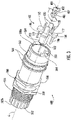
FIG. 3 is an exploded isometric view of a cable strand anchoring assembly, including the cable strand anchoring device shown inFIGs. 1 and2 , in accordance with embodiments disclosed herein; -
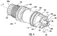
FIG. 4 is an assembled isometric view of the cable strand anchoring assembly shown inFIG. 3 , in accordance with embodiments disclosed herein; -
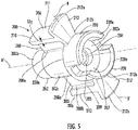
FIG. 5 is an isometric view of another cable strand anchoring device in accordance with embodiments disclosed herein; and -
FIG. 6 is an isometric view of yet another cable strand anchoring device in accordance with embodiments disclosed herein. - Various exemplary embodiments of the disclosure will now be described with particular reference to the drawings. Exemplary embodiments of the present disclosure may take on various modifications and alterations without departing from the spirit and scope of the disclosure. Accordingly, it is to be understood that the embodiments of the present disclosure are not to be limited to the following described exemplary embodiments, but are to be controlled by the features and limitations set forth in the claims and any equivalents thereof.
- Unless otherwise indicated, all numbers expressing feature sizes, amounts, and physical properties used in the specification and claims are to be understood as being modified in all instances by the term "about." Accordingly, unless indicated to the contrary, the numerical parameters set forth in the foregoing specification and attached claims are approximations that can vary depending upon the desired properties sought to be obtained by those skilled in the art utilizing the teachings disclosed herein.
- As used in this specification and the appended claims, the singular forms "a," "an," and "the" encompass embodiments having plural referents, unless the content clearly dictates otherwise. As used in this specification and the appended claims, the term "or" is generally employed in its sense including "and/or" unless the content clearly dictates otherwise.
- Spatially related terms, including but not limited to, "lower," "upper," "beneath," "below," "above," and "on top," if used herein, are utilized for ease of description to describe spatial relationships of an element(s) to another. Such spatially related terms encompass different orientations of the device in use or operation in addition to the particular orientations depicted in the figures and described herein. For example, if an object depicted in the figures is turned over or flipped over, portions previously described as below or beneath other elements would then be above those other elements.
- Cartesian coordinates are used in some of the Figures for reference and are not intended to be limiting as to direction or orientation.
- For purposes of description herein, the terms "upper," "lower," "right," "left," "rear," "front," "vertical," "horizontal," "top," "bottom," "side," and derivatives thereof, shall relate to the disclosure as oriented with respect to the Cartesian coordinates in the corresponding Figure, unless stated otherwise. However, it is to be understood that the disclosure may assume various alternative orientations, except where expressly specified to the contrary.
- For the purposes of describing and defining the subject matter of the disclosure it is noted that the terms "substantially" and "generally" may be utilized herein to represent the inherent degree of uncertainty that may be attributed to any quantitative comparison, value, measurement, or other representation.
-
FIG. 1 illustrates a cablestrand anchoring device 100 configured for coupling to a telecommunications enclosure and/or one or more components of a telecommunications enclosure. The cablestrand anchoring device 100 includes ahub 102, extending from afirst hub end 102a to asecond hub end 102b. In this embodiment, a thru-hole 104 is also defined within thehub 102 to extend from thefirst hub end 102a to thesecond hub end 102b. The thru-hole 104 is configured for routing of at least one cable strand. However, alternatively or in addition, one or more cable strands may be routed around the hub exterior 102e. The thru-hole 104 may also be configured for assembly with a fastening element, as will be described with respect toFIGs. 3 and4 . - Referring particularly to
FIG. 2 , thehub 102 is further defined by a plurality of hub walls, specifically afirst hub wall 103, asecond hub wall 105, and athird hub wall 107. Each hub wall has respective hub wall thicknesses HW1, HW2, HW3, where the second hub wall thickness HW2 is larger than the third hub wall thickness HW3, and where the third hub wall thickness HW3 is larger than the first hub wall thickness HW1. - Extending outwardly from the
hub 102 and specifically the hub exterior 102e is a plurality of cablestrand positioning elements 106. Each cablestrand positioning element 106 is positioned symmetrically in a radial arrangement with respect to a longitudinal axis A, which extends through the center of the cable anchoring device. In the arrangement shown inFIG. 1 , there are four cable strand positioning elements which are positioned symmetrically in a radial arrangement. Specifically, each cable strand positioning element has a central axis B, B', C, C' positioned a predetermined angular distance PD with respect to each other. Preferably, the predetermined angular distance PD is substantially equal such that the arrangement of the plurality of cable strand positioning elements is symmetrical, as particularly shown inFIG. 1 . In this exemplary embodiment, the predetermined angular distance PD is about 90 degrees. - The number of positioning elements shown in
FIG. 1 should not be construed as limiting. Fewer or additional cable strand positioning elements may be integrally and monolithically attached to thehub 102. Accordingly, a predetermined angular distance PD will be in part based on the symmetrical positioning of the plurality of cable strand positioning elements such that the predetermined angular distance PD is equal to 360 divided by the total number N of cable strand positioning elements, where PD has a maximum value of 180 degrees and where:
- Accordingly, where there are three (3) cable strand positioning elements, the predetermined angular distance will be about 120 degrees and where there are six (6) cable positioning elements, the predetermined angular distance PD will be about 60 degrees.
- Each cable
strand positioning element 106 includes a stabilizingportion 108, anarc portion 110, and alobe 112, The stabilizingportion 108 has aninnermost end 108a integrally and monolithically attached to the hub exterior 102e and anoutermost end 108b integrally and monolithically attached to thelobe 112. Extending from theoutermost end 108b is anarc portion 110. Thearc portion 110 preferably has an arc thickness TA, acurved top 111 and a plurality ofunderside areas 109 with one or more of the plurality of underside areas being attached to theoutermost end 108b of the stabilizingportion 108. The arc thickness TA varies based upon the curvature of thecurved top 111. - The
lobe 112 is monolithically formed with the hub, the stabilizing portion, the arc portion. Thelobe 112 includes anoutermost lobe end 112a, which preferably has a curved profile, and aninnermost lobe end 112b. Theinnermost lobe end 112b is monolithically formed with thehub 102, as particularly shown inFIG. 2 . - Referring to
FIG. 2 , thearc portion 110 and thelobe 112 may be further defined with respect to each other by an angular distance α, where α is measured from an edge 110e of the arc portion to a rear face 114r of thelobe 112. - Monolithically formed with the
hub 102 and thelobe 112 is a plurality of strand anchors 120. Eachstrand anchor 120 includes anoutermost end 120a and aninnermost end 120b, with theoutermost end 120a preferably being curved. - The
lobe 112 and thestrand anchor 120 may be further defined with respect to each other by an angular distance β, where β is measured from an edge 112e of the strand anchor to aforward face 114f of thelobe 112. The plurality of strand anchors 120 are also positioned symmetrically in a radial arrangement with respect to a longitudinal axis A, which extends through the center of the cable anchoring device. The number of strand anchors also preferably corresponds to the number of cable strand positioning elements. -
FIGs. 3 and4 illustrate exploded and assembled views of a cablestrand anchoring assembly 600, including the cablestrand anchoring device 100 shown inFIGs. 1 and2 , and amodular component 500 configured for assembly with a telecommunications enclosures. Such modular components may be part of an external cable assembly such as the External Cable Assembly Module (ECAM) sold by Corning, Inc. - The
modular component 500 has abored end 500a, defined by aninner diameter 550, and agripper end 500b. A portion of the outer surface of themodular component 500 includes a plurality ofribs 552 that facilitate hand gripping. Thebored end 500a is configured to receive a portion of a cable strand anchoring device. When assembled with the cablestrand anchoring device 100, as shown inFIGs. 1 and2 , thebored end 500a is configured to receive at least thehub 102 and the plurality of cablestrand positioning elements 106. The outer surface of themodular component 500 also has fastening feature, configured as a plurality ofthreads 556, as well as a series ofgripping elements - The
modular component 500 also includes a plurality of tabs 554 extending axially outward from the bored end 550a. Each tab 554 is configured for positioning adjacent to alobe 112, as particularly shown inFIG. 4 . -
FIGs. 3 and4 additionally shows how afastening element 400 may be coupled with the cablestrand anchoring device 100. Thefastening element 400 is configured as a screw, having ahead 401 and afastener body 406, having a plurality offastener threads 407. Thehead 401 is positionable and capable of being centered within the plurality of strand anchors 120. Thefastener body 406 is positionable in the thru-hole 104 of the cablestrand anchoring device 100. -
FIG. 5 illustrates another embodiment of a cablestrand anchoring device 200 configured for coupling to a telecommunications enclosure and/or one or more components of a telecommunications enclosure. As such, the cablestrand anchoring device 200 can also be coupled to themodular component 500 shown inFIGs. 3 and4 . The cablestrand anchoring device 200 includes ahub 202, extending from afirst hub end 202a to asecond hub end 202b. - Similar to the first embodiment, a thru-
hole 204 is defined within thehub 202 to extend from thefirst hub end 202a to thesecond hub end 202b. The thru-hole 204 is configured for routing of at least one cable strand. However, alternatively or in addition, one or more cable strands may be routed around the hub exterior 202e. The thru-hole 204 may also be configured for assembly with a fastening element, as will be described with respect toFIGs. 3 and4 . Thehub 202 is further defined by a plurality of hub walls, specifically a first hub wall 203 and asecond hub wall 205. Each hub wall has respective hub wall thicknesses, where the second hub wall thickness is larger than the first hub wall thickness. - Extending outwardly from the
hub 202 and specifically the hub exterior 202e is a plurality of a plurality of cablestrand positioning elements 206. Each cablestrand positioning element 206 is positioned symmetrically in a radial arrangement with respect to a longitudinal axis A', which extends through the center of the cable anchoring device. In the arrangement shown inFIG. 5 , there are two cable strand positioning elements which are positioned symmetrically in a radial arrangement. Specifically, each cable strand positioning element has a central axis B, B' positioned a predetermined angular distance PD with respect to each other. Here, the predetermined angular distance PD is about 180 degrees. - Each cable
strand positioning element 206 includes a stabilizingportion 208, anarc portion 210, and alobe 212. The stabilizingportion 208 has aninnermost end 208a integrally and monolithically attached to the hub exterior 202e and anoutermost end 208b integrally and monolithically attached to thelobe 212. Extending from theoutermost end 208b is thearc portion 210. Thearc portion 210 preferably has an arc thickness TA2, acurved top 211 and a plurality ofunderside areas 209 with one or more of the plurality of underside areas being attached to theoutermost end 208b of the stabilizingportion 208. The arc thickness TA varies based upon the curvature of thecurved top 211. - The
lobe 212 is monolithically formed with the hub, the stabilizing portion, the arc portion. Thelobe 212 includes anoutermost lobe end 212a, which preferably has a curved profile, and aninnermost lobe end 212b. Theinnermost lobe end 212b is monolithically formed with thehub 202. - Monolithically formed with the
hub 202 and thelobe 212 is a plurality of strand anchors 220. Eachstrand anchor 220 includes anoutermost end 220a, with theoutermost end 220a preferably having a curved profile. The plurality of strand anchors 220 are also positioned symmetrically in a radial arrangement with respect to a longitudinal axis A', which extends through the center of the cable anchoring device. -
FIG. 6 illustrates an alternative embodiment of a cablestrand anchoring device 300 configured for coupling to a telecommunications enclosure and/or one or more components of a telecommunications enclosure such as themodular component 500, shown inFIGs. 3 and4 . The cablestrand anchoring device 300 has the same configurations for ahub 302, and a plurality of cablestrand positioning elements 306, as shown and described with respect to the first embodiment. Thus each cable strand positioning element includes a stabilizingportion 308, anarc portion 310, and alobe 312. This embodiment of the cable strand anchoring devices includes alternatively formed strand anchors 320, having astrand gripping hub 340 positioned therein. - Monolithically formed with the
hub 302 and thelobe 312 is a plurality of strand anchors 320. The plurality of strand anchors 320 is configured for receiving strands of a cable and/or a cable tie or other equivalent components capable of securing strands to the strand anchors. The plurality of strand anchors 320 is also positioned symmetrically in a radial arrangement with respect to a longitudinal axis A", which extends through the center of thecable anchoring device 300. Eachstrand anchor 320 includes ananchor body 322 having afirst body end 322a, which is monolithically formed with the hub and asecond body end 322b, which is cantilevered. The body additionally includes a plurality ofside body portions 324 and acentral anchor portion 326, having sections positioned between the side anchor portions and between twolobes 312. In this embodiment, the plurality ofside body portions 324 includes afirst body portion 324a and asecond body portion 324a'. The strand anchor additionally includes atab portion 328, extending radially outward with respect to longitudinal axis A". Thetab portion 328 is configured to prevent slippage of cable strands, a cable tie, or another elements which may be positioned around the strand anchors 320. - Positioned centrally with respect to the plurality of strand anchors 320 is a
strand gripping hub 340. Thestrand gripping hub 340 includes agripping hub body 342, having a firsthub body end 342a monolithically formed with thehub 302 and a cantilevered secondhub body end 342b. Thegipping hub body 342 also includes a plurality ofridges 344, which are configured to act as a gripping surface when cable strands are routed around thestrand gripping hub 340. - It will be apparent to those skilled in the art that various modifications and variations can be made without departing from the spirit or scope of the invention. Since modifications combinations, sub-combinations and variations of the disclosed embodiments incorporating the spirit and substance of the invention may occur to persons skilled in the art, the invention should be construed to include everything within the scope of the appended claims and their equivalents.
Claims (15)
- A cable strand anchoring device, comprising:a hub extending from a first hub end to a second hub end;a plurality of cable strand positioning elements, extending from the hub, wherein each cable positioning element comprises:a stabilizing portion monolithically formed with the hub,an arc portion monolithically formed with the stabilizing portion, anda lobe monolithically formed with the hub, the stabilizing portion and the arc portion; anda plurality of strand anchors monolithically formed with the hub and the lobe,wherein the cable strand anchoring device is configured to receive strands of a cable.
- The cable strand anchoring device of claim 1, wherein each of the plurality of cable strand positioning elements extend radially and symmetrically outward from the hub.
- The cable strand anchoring device of claim 2, wherein the symmetrical positioning of the strand positioning element is defined by a predetermined angular distance, having a maximum of about 180 degrees.
- The cable strand anchoring device of any one of claims 1-3, wherein each of the plurality of strand anchors has an anchor edge positioned at an anchoring angle B with respect to a front face of the lobe.
- The cable strand anchoring device of any one of claims 1-3, wherein the positioning of the plurality of cable strand positioning elements is defined by predetermined angular distance, and wherein the predetermined angular distance equals 360 divided by the total number N of cable strand positioning elements.
- The cable strand anchoring device of any one of claims 1-5, wherein defined within the hub is a thru-hole that extends from the first hub end to the second hub end, and wherein the thru-hole is configured for routing of at least one cable strand.
- The cable strand anchoring device of claim 6, wherein the thru-hole is configured to receive a fastening element.
- The cable strand anchoring device of any one of claims 1-7, wherein the hub comprises a plurality of hub walls.
- The cable strand anchoring device of any one of claims 1-6, wherein the lobe extends substantially perpendicular with respect to the stabilizing portion.
- A cable strand anchoring device, comprising:a hub extending from a first hub end to a second hub end;a plurality of cable strand positioning elements, extending from the hub, wherein each cable positioning element comprises:a stabilizing portion monolithically formed with the hub,an arc portion monolithically formed with the stabilizing portion, anda lobe monolithically formed with the hub, the stabilizing portion and the arc portion;a plurality of strand anchors monolithically formed with the hub and the lobe,a strand gripping hub monolithically formed with the hub and positioned within the plurality of strand anchors,wherein the cable strand anchoring device is configured to receive strands of a cable.
- The cable strand anchoring device of claim 10, wherein each of the plurality of cable strand positioning elements extend radially and symmetrically outward from the hub.
- The cable strand anchoring device of any one of claims 10-11, wherein the symmetrical positioning of the strand positioning element is defined by a predetermined angular distance, having a maximum of about 180 degrees.
- The cable strand anchoring device of any one of claims 10-12, wherein each of the plurality of strand anchors comprises an anchor body, having a first body end, which is monolithically formed with the hub and a second body end, which is cantilevered.
- The cable strand anchoring device of any one of claims 10-13, wherein each of the plurality of strand anchors comprises a plurality of side body portions, a central anchor portion, and a tab portion, and wherein the tab portion extends radially outward from the central anchor portion.
- The cable strand anchoring device of any one of claims 10-14, wherein the strand gripping hub comprises a plurality of ridges that act as a gripping surface when cable strands are routed around the strand gripping hub.
Applications Claiming Priority (1)
| Application Number | Priority Date | Filing Date | Title |
|---|---|---|---|
| US202063088594P | 2020-10-07 | 2020-10-07 |
Publications (2)
| Publication Number | Publication Date |
|---|---|
| EP3982180A1 true EP3982180A1 (en) | 2022-04-13 |
| EP3982180B1 EP3982180B1 (en) | 2025-03-05 |
Family
ID=78078061
Family Applications (1)
| Application Number | Title | Priority Date | Filing Date |
|---|---|---|---|
| EP21200706.6A Active EP3982180B1 (en) | 2020-10-07 | 2021-10-04 | Cable strand anchoring devices and assemblies |
Country Status (2)
| Country | Link |
|---|---|
| US (1) | US11817685B2 (en) |
| EP (1) | EP3982180B1 (en) |
Citations (3)
| Publication number | Priority date | Publication date | Assignee | Title |
|---|---|---|---|---|
| US5013124A (en) * | 1989-01-05 | 1991-05-07 | Codenoll Technology Corporation | Method and apparatus for connecting optical fibers |
| US20180055550A1 (en) * | 2016-08-30 | 2018-03-01 | Cable Fix LLC | Deployable anchor for bone fixation |
| US20200057221A1 (en) * | 2017-04-25 | 2020-02-20 | Corning Research & Development Corporation | Sealing body for telecommunication cables |
Family Cites Families (7)
| Publication number | Priority date | Publication date | Assignee | Title |
|---|---|---|---|---|
| US3667783A (en) * | 1970-07-08 | 1972-06-06 | Thomas & Betts Corp | Liquid tight strain relief connector |
| CA1040280A (en) * | 1975-04-29 | 1978-10-10 | General Electric Company | Fast torque screw retention of electrical connector housing |
| US4114974A (en) * | 1977-08-29 | 1978-09-19 | General Electric Company | Dust shield for cap and connector |
| US5374017A (en) * | 1989-02-17 | 1994-12-20 | Martin; William B. | Cable fitting |
| US5211576A (en) * | 1991-09-27 | 1993-05-18 | Glenair, Inc. | Strain relief cable clamp |
| ES2190055T3 (en) * | 1997-12-03 | 2003-07-16 | Palazzoli Spa | DEVICE FOR HOLDING THE CABLE IN ELECTRIC POWER OUTLETS OR PLUGS. |
| US9343890B2 (en) * | 2013-01-23 | 2016-05-17 | Thomas & Betts International Llc | Electrical cable restrain device using a double wedge chuck |
-
2021
- 2021-09-29 US US17/488,371 patent/US11817685B2/en active Active
- 2021-10-04 EP EP21200706.6A patent/EP3982180B1/en active Active
Patent Citations (3)
| Publication number | Priority date | Publication date | Assignee | Title |
|---|---|---|---|---|
| US5013124A (en) * | 1989-01-05 | 1991-05-07 | Codenoll Technology Corporation | Method and apparatus for connecting optical fibers |
| US20180055550A1 (en) * | 2016-08-30 | 2018-03-01 | Cable Fix LLC | Deployable anchor for bone fixation |
| US20200057221A1 (en) * | 2017-04-25 | 2020-02-20 | Corning Research & Development Corporation | Sealing body for telecommunication cables |
Also Published As
| Publication number | Publication date |
|---|---|
| US11817685B2 (en) | 2023-11-14 |
| EP3982180B1 (en) | 2025-03-05 |
| US20220109291A1 (en) | 2022-04-07 |
Similar Documents
| Publication | Publication Date | Title |
|---|---|---|
| US11619795B2 (en) | Fiber optic cable fixation device and fiber optic cable mounting system comprising same | |
| US5375185A (en) | Apparatus for storing and organizing spliced optical fibers | |
| US8660397B2 (en) | Multi-layer module | |
| US20060215980A1 (en) | Splice tray arrangement | |
| US20110268415A1 (en) | Multi-configurable splice holder | |
| US20120134639A1 (en) | Module with adapter side entry opening | |
| EP0735394A2 (en) | Optical fibre clamping device | |
| JPH09502282A (en) | Optical fiber organizer | |
| EP2851720B1 (en) | Optical fiber unit for optical fiber sensor | |
| CA2247674A1 (en) | Fiber optic protective member with removable section to facilitate separation thereof | |
| US20040252960A1 (en) | Fiber management frame for securely retaining optical fiber connection trays | |
| HU217730B (en) | Structure for separate bonding and arrangement of optical fibers | |
| US10718919B2 (en) | Field-installable optical module with configurable cable attachment and internal cable management features | |
| EP2851719A1 (en) | Optical fiber unit for optical fiber sensor | |
| EP0646811A2 (en) | Breakout for optical fibres | |
| US11163130B2 (en) | Cable fixation assembly for a cable having a strength member | |
| CA2182859A1 (en) | A cable routing device | |
| EP2062081A1 (en) | Optical fiber slack storage for splice trays and splice assemblies | |
| EP3982180B1 (en) | Cable strand anchoring devices and assemblies | |
| EP4481453A1 (en) | Fiber optic cable fastener assembly | |
| EP2626732B1 (en) | Optical connector with sleeve | |
| JPH085878A (en) | Optical cable having u-shaped carrier whose crushing performance is improved | |
| US20210341696A1 (en) | Unitized fiber optic cables | |
| AU2018250693B2 (en) | Flat drop cable with features for enhanced stripability | |
| US6188827B1 (en) | Attenuator element for a buildout system |
Legal Events
| Date | Code | Title | Description |
|---|---|---|---|
| PUAI | Public reference made under article 153(3) epc to a published international application that has entered the european phase |
Free format text: ORIGINAL CODE: 0009012 |
|
| STAA | Information on the status of an ep patent application or granted ep patent |
Free format text: STATUS: THE APPLICATION HAS BEEN PUBLISHED |
|
| AK | Designated contracting states |
Kind code of ref document: A1 Designated state(s): AL AT BE BG CH CY CZ DE DK EE ES FI FR GB GR HR HU IE IS IT LI LT LU LV MC MK MT NL NO PL PT RO RS SE SI SK SM TR |
|
| STAA | Information on the status of an ep patent application or granted ep patent |
Free format text: STATUS: REQUEST FOR EXAMINATION WAS MADE |
|
| 17P | Request for examination filed |
Effective date: 20221013 |
|
| RBV | Designated contracting states (corrected) |
Designated state(s): AL AT BE BG CH CY CZ DE DK EE ES FI FR GB GR HR HU IE IS IT LI LT LU LV MC MK MT NL NO PL PT RO RS SE SI SK SM TR |
|
| GRAP | Despatch of communication of intention to grant a patent |
Free format text: ORIGINAL CODE: EPIDOSNIGR1 |
|
| STAA | Information on the status of an ep patent application or granted ep patent |
Free format text: STATUS: GRANT OF PATENT IS INTENDED |
|
| INTG | Intention to grant announced |
Effective date: 20240927 |
|
| GRAS | Grant fee paid |
Free format text: ORIGINAL CODE: EPIDOSNIGR3 |
|
| GRAA | (expected) grant |
Free format text: ORIGINAL CODE: 0009210 |
|
| STAA | Information on the status of an ep patent application or granted ep patent |
Free format text: STATUS: THE PATENT HAS BEEN GRANTED |
|
| AK | Designated contracting states |
Kind code of ref document: B1 Designated state(s): AL AT BE BG CH CY CZ DE DK EE ES FI FR GB GR HR HU IE IS IT LI LT LU LV MC MK MT NL NO PL PT RO RS SE SI SK SM TR |
|
| REG | Reference to a national code |
Ref country code: GB Ref legal event code: FG4D |
|
| REG | Reference to a national code |
Ref country code: CH Ref legal event code: EP |
|
| REG | Reference to a national code |
Ref country code: DE Ref legal event code: R096 Ref document number: 602021027065 Country of ref document: DE |
|
| REG | Reference to a national code |
Ref country code: IE Ref legal event code: FG4D |
|
| PG25 | Lapsed in a contracting state [announced via postgrant information from national office to epo] |
Ref country code: RS Free format text: LAPSE BECAUSE OF FAILURE TO SUBMIT A TRANSLATION OF THE DESCRIPTION OR TO PAY THE FEE WITHIN THE PRESCRIBED TIME-LIMIT Effective date: 20250605 |
|
| PG25 | Lapsed in a contracting state [announced via postgrant information from national office to epo] |
Ref country code: FI Free format text: LAPSE BECAUSE OF FAILURE TO SUBMIT A TRANSLATION OF THE DESCRIPTION OR TO PAY THE FEE WITHIN THE PRESCRIBED TIME-LIMIT Effective date: 20250305 |
|
| REG | Reference to a national code |
Ref country code: NL Ref legal event code: MP Effective date: 20250305 |
|
| PG25 | Lapsed in a contracting state [announced via postgrant information from national office to epo] |
Ref country code: ES Free format text: LAPSE BECAUSE OF FAILURE TO SUBMIT A TRANSLATION OF THE DESCRIPTION OR TO PAY THE FEE WITHIN THE PRESCRIBED TIME-LIMIT Effective date: 20250305 |
|
| REG | Reference to a national code |
Ref country code: LT Ref legal event code: MG9D |
|
| PG25 | Lapsed in a contracting state [announced via postgrant information from national office to epo] |
Ref country code: NO Free format text: LAPSE BECAUSE OF FAILURE TO SUBMIT A TRANSLATION OF THE DESCRIPTION OR TO PAY THE FEE WITHIN THE PRESCRIBED TIME-LIMIT Effective date: 20250605 |
|
| PG25 | Lapsed in a contracting state [announced via postgrant information from national office to epo] |
Ref country code: HR Free format text: LAPSE BECAUSE OF FAILURE TO SUBMIT A TRANSLATION OF THE DESCRIPTION OR TO PAY THE FEE WITHIN THE PRESCRIBED TIME-LIMIT Effective date: 20250305 |
|
| PG25 | Lapsed in a contracting state [announced via postgrant information from national office to epo] |
Ref country code: LV Free format text: LAPSE BECAUSE OF FAILURE TO SUBMIT A TRANSLATION OF THE DESCRIPTION OR TO PAY THE FEE WITHIN THE PRESCRIBED TIME-LIMIT Effective date: 20250305 |
|
| PG25 | Lapsed in a contracting state [announced via postgrant information from national office to epo] |
Ref country code: GR Free format text: LAPSE BECAUSE OF FAILURE TO SUBMIT A TRANSLATION OF THE DESCRIPTION OR TO PAY THE FEE WITHIN THE PRESCRIBED TIME-LIMIT Effective date: 20250606 Ref country code: BG Free format text: LAPSE BECAUSE OF FAILURE TO SUBMIT A TRANSLATION OF THE DESCRIPTION OR TO PAY THE FEE WITHIN THE PRESCRIBED TIME-LIMIT Effective date: 20250305 |
|
| REG | Reference to a national code |
Ref country code: AT Ref legal event code: MK05 Ref document number: 1773409 Country of ref document: AT Kind code of ref document: T Effective date: 20250305 |
|
| PG25 | Lapsed in a contracting state [announced via postgrant information from national office to epo] |
Ref country code: NL Free format text: LAPSE BECAUSE OF FAILURE TO SUBMIT A TRANSLATION OF THE DESCRIPTION OR TO PAY THE FEE WITHIN THE PRESCRIBED TIME-LIMIT Effective date: 20250305 |
|
| PG25 | Lapsed in a contracting state [announced via postgrant information from national office to epo] |
Ref country code: SE Free format text: LAPSE BECAUSE OF FAILURE TO SUBMIT A TRANSLATION OF THE DESCRIPTION OR TO PAY THE FEE WITHIN THE PRESCRIBED TIME-LIMIT Effective date: 20250305 |
|
| PG25 | Lapsed in a contracting state [announced via postgrant information from national office to epo] |
Ref country code: SM Free format text: LAPSE BECAUSE OF FAILURE TO SUBMIT A TRANSLATION OF THE DESCRIPTION OR TO PAY THE FEE WITHIN THE PRESCRIBED TIME-LIMIT Effective date: 20250305 |
|
| PG25 | Lapsed in a contracting state [announced via postgrant information from national office to epo] |
Ref country code: PT Free format text: LAPSE BECAUSE OF FAILURE TO SUBMIT A TRANSLATION OF THE DESCRIPTION OR TO PAY THE FEE WITHIN THE PRESCRIBED TIME-LIMIT Effective date: 20250707 |
|
| PG25 | Lapsed in a contracting state [announced via postgrant information from national office to epo] |
Ref country code: IT Free format text: LAPSE BECAUSE OF FAILURE TO SUBMIT A TRANSLATION OF THE DESCRIPTION OR TO PAY THE FEE WITHIN THE PRESCRIBED TIME-LIMIT Effective date: 20250305 Ref country code: PL Free format text: LAPSE BECAUSE OF FAILURE TO SUBMIT A TRANSLATION OF THE DESCRIPTION OR TO PAY THE FEE WITHIN THE PRESCRIBED TIME-LIMIT Effective date: 20250305 |
|
| PG25 | Lapsed in a contracting state [announced via postgrant information from national office to epo] |
Ref country code: AT Free format text: LAPSE BECAUSE OF FAILURE TO SUBMIT A TRANSLATION OF THE DESCRIPTION OR TO PAY THE FEE WITHIN THE PRESCRIBED TIME-LIMIT Effective date: 20250305 |
|
| PG25 | Lapsed in a contracting state [announced via postgrant information from national office to epo] |
Ref country code: CZ Free format text: LAPSE BECAUSE OF FAILURE TO SUBMIT A TRANSLATION OF THE DESCRIPTION OR TO PAY THE FEE WITHIN THE PRESCRIBED TIME-LIMIT Effective date: 20250305 Ref country code: EE Free format text: LAPSE BECAUSE OF FAILURE TO SUBMIT A TRANSLATION OF THE DESCRIPTION OR TO PAY THE FEE WITHIN THE PRESCRIBED TIME-LIMIT Effective date: 20250305 |
|
| PG25 | Lapsed in a contracting state [announced via postgrant information from national office to epo] |
Ref country code: RO Free format text: LAPSE BECAUSE OF FAILURE TO SUBMIT A TRANSLATION OF THE DESCRIPTION OR TO PAY THE FEE WITHIN THE PRESCRIBED TIME-LIMIT Effective date: 20250305 |
|
| PG25 | Lapsed in a contracting state [announced via postgrant information from national office to epo] |
Ref country code: SK Free format text: LAPSE BECAUSE OF FAILURE TO SUBMIT A TRANSLATION OF THE DESCRIPTION OR TO PAY THE FEE WITHIN THE PRESCRIBED TIME-LIMIT Effective date: 20250305 |
|
| PG25 | Lapsed in a contracting state [announced via postgrant information from national office to epo] |
Ref country code: IS Free format text: LAPSE BECAUSE OF FAILURE TO SUBMIT A TRANSLATION OF THE DESCRIPTION OR TO PAY THE FEE WITHIN THE PRESCRIBED TIME-LIMIT Effective date: 20250705 |
|
| REG | Reference to a national code |
Ref country code: DE Ref legal event code: R097 Ref document number: 602021027065 Country of ref document: DE |
|
| PLBE | No opposition filed within time limit |
Free format text: ORIGINAL CODE: 0009261 |
|
| STAA | Information on the status of an ep patent application or granted ep patent |
Free format text: STATUS: NO OPPOSITION FILED WITHIN TIME LIMIT |
|
| PG25 | Lapsed in a contracting state [announced via postgrant information from national office to epo] |
Ref country code: DK Free format text: LAPSE BECAUSE OF FAILURE TO SUBMIT A TRANSLATION OF THE DESCRIPTION OR TO PAY THE FEE WITHIN THE PRESCRIBED TIME-LIMIT Effective date: 20250305 |
|
| REG | Reference to a national code |
Ref country code: CH Ref legal event code: L10 Free format text: ST27 STATUS EVENT CODE: U-0-0-L10-L00 (AS PROVIDED BY THE NATIONAL OFFICE) Effective date: 20260114 |
|
| 26N | No opposition filed |
Effective date: 20251208 |