EP3982070A1 - Door body for refrigerator, refrigerator and manufacturing method of door body - Google Patents
Door body for refrigerator, refrigerator and manufacturing method of door body Download PDFInfo
- Publication number
- EP3982070A1 EP3982070A1 EP19931607.6A EP19931607A EP3982070A1 EP 3982070 A1 EP3982070 A1 EP 3982070A1 EP 19931607 A EP19931607 A EP 19931607A EP 3982070 A1 EP3982070 A1 EP 3982070A1
- Authority
- EP
- European Patent Office
- Prior art keywords
- door
- door frame
- air discharge
- receiving cavity
- communicated
- Prior art date
- Legal status (The legal status is an assumption and is not a legal conclusion. Google has not performed a legal analysis and makes no representation as to the accuracy of the status listed.)
- Granted
Links
Images




Classifications
-
- F—MECHANICAL ENGINEERING; LIGHTING; HEATING; WEAPONS; BLASTING
- F25—REFRIGERATION OR COOLING; COMBINED HEATING AND REFRIGERATION SYSTEMS; HEAT PUMP SYSTEMS; MANUFACTURE OR STORAGE OF ICE; LIQUEFACTION SOLIDIFICATION OF GASES
- F25D—REFRIGERATORS; COLD ROOMS; ICE-BOXES; COOLING OR FREEZING APPARATUS NOT OTHERWISE PROVIDED FOR
- F25D23/00—General constructional features
- F25D23/02—Doors; Covers
-
- F—MECHANICAL ENGINEERING; LIGHTING; HEATING; WEAPONS; BLASTING
- F25—REFRIGERATION OR COOLING; COMBINED HEATING AND REFRIGERATION SYSTEMS; HEAT PUMP SYSTEMS; MANUFACTURE OR STORAGE OF ICE; LIQUEFACTION SOLIDIFICATION OF GASES
- F25D—REFRIGERATORS; COLD ROOMS; ICE-BOXES; COOLING OR FREEZING APPARATUS NOT OTHERWISE PROVIDED FOR
- F25D23/00—General constructional features
- F25D23/02—Doors; Covers
- F25D23/028—Details
-
- B—PERFORMING OPERATIONS; TRANSPORTING
- B29—WORKING OF PLASTICS; WORKING OF SUBSTANCES IN A PLASTIC STATE IN GENERAL
- B29C—SHAPING OR JOINING OF PLASTICS; SHAPING OF MATERIAL IN A PLASTIC STATE, NOT OTHERWISE PROVIDED FOR; AFTER-TREATMENT OF THE SHAPED PRODUCTS, e.g. REPAIRING
- B29C33/00—Moulds or cores; Details thereof or accessories therefor
- B29C33/10—Moulds or cores; Details thereof or accessories therefor with incorporated venting means
-
- B—PERFORMING OPERATIONS; TRANSPORTING
- B29—WORKING OF PLASTICS; WORKING OF SUBSTANCES IN A PLASTIC STATE IN GENERAL
- B29C—SHAPING OR JOINING OF PLASTICS; SHAPING OF MATERIAL IN A PLASTIC STATE, NOT OTHERWISE PROVIDED FOR; AFTER-TREATMENT OF THE SHAPED PRODUCTS, e.g. REPAIRING
- B29C44/00—Shaping by internal pressure generated in the material, e.g. swelling or foaming ; Producing porous or cellular expanded plastics articles
- B29C44/02—Shaping by internal pressure generated in the material, e.g. swelling or foaming ; Producing porous or cellular expanded plastics articles for articles of definite length, i.e. discrete articles
- B29C44/12—Incorporating or moulding on preformed parts, e.g. inserts or reinforcements
- B29C44/18—Filling preformed cavities
-
- B—PERFORMING OPERATIONS; TRANSPORTING
- B29—WORKING OF PLASTICS; WORKING OF SUBSTANCES IN A PLASTIC STATE IN GENERAL
- B29C—SHAPING OR JOINING OF PLASTICS; SHAPING OF MATERIAL IN A PLASTIC STATE, NOT OTHERWISE PROVIDED FOR; AFTER-TREATMENT OF THE SHAPED PRODUCTS, e.g. REPAIRING
- B29C44/00—Shaping by internal pressure generated in the material, e.g. swelling or foaming ; Producing porous or cellular expanded plastics articles
- B29C44/34—Auxiliary operations
-
- B—PERFORMING OPERATIONS; TRANSPORTING
- B29—WORKING OF PLASTICS; WORKING OF SUBSTANCES IN A PLASTIC STATE IN GENERAL
- B29C—SHAPING OR JOINING OF PLASTICS; SHAPING OF MATERIAL IN A PLASTIC STATE, NOT OTHERWISE PROVIDED FOR; AFTER-TREATMENT OF THE SHAPED PRODUCTS, e.g. REPAIRING
- B29C44/00—Shaping by internal pressure generated in the material, e.g. swelling or foaming ; Producing porous or cellular expanded plastics articles
- B29C44/34—Auxiliary operations
- B29C44/35—Component parts; Details or accessories
-
- B—PERFORMING OPERATIONS; TRANSPORTING
- B29—WORKING OF PLASTICS; WORKING OF SUBSTANCES IN A PLASTIC STATE IN GENERAL
- B29C—SHAPING OR JOINING OF PLASTICS; SHAPING OF MATERIAL IN A PLASTIC STATE, NOT OTHERWISE PROVIDED FOR; AFTER-TREATMENT OF THE SHAPED PRODUCTS, e.g. REPAIRING
- B29C44/00—Shaping by internal pressure generated in the material, e.g. swelling or foaming ; Producing porous or cellular expanded plastics articles
- B29C44/34—Auxiliary operations
- B29C44/58—Moulds
-
- B—PERFORMING OPERATIONS; TRANSPORTING
- B29—WORKING OF PLASTICS; WORKING OF SUBSTANCES IN A PLASTIC STATE IN GENERAL
- B29C—SHAPING OR JOINING OF PLASTICS; SHAPING OF MATERIAL IN A PLASTIC STATE, NOT OTHERWISE PROVIDED FOR; AFTER-TREATMENT OF THE SHAPED PRODUCTS, e.g. REPAIRING
- B29C44/00—Shaping by internal pressure generated in the material, e.g. swelling or foaming ; Producing porous or cellular expanded plastics articles
- B29C44/34—Auxiliary operations
- B29C44/58—Moulds
- B29C44/588—Moulds with means for venting, e.g. releasing foaming gas
-
- B—PERFORMING OPERATIONS; TRANSPORTING
- B29—WORKING OF PLASTICS; WORKING OF SUBSTANCES IN A PLASTIC STATE IN GENERAL
- B29L—INDEXING SCHEME ASSOCIATED WITH SUBCLASS B29C, RELATING TO PARTICULAR ARTICLES
- B29L2031/00—Other particular articles
- B29L2031/762—Household appliances
- B29L2031/7622—Refrigerators
-
- F—MECHANICAL ENGINEERING; LIGHTING; HEATING; WEAPONS; BLASTING
- F25—REFRIGERATION OR COOLING; COMBINED HEATING AND REFRIGERATION SYSTEMS; HEAT PUMP SYSTEMS; MANUFACTURE OR STORAGE OF ICE; LIQUEFACTION SOLIDIFICATION OF GASES
- F25D—REFRIGERATORS; COLD ROOMS; ICE-BOXES; COOLING OR FREEZING APPARATUS NOT OTHERWISE PROVIDED FOR
- F25D23/00—General constructional features
- F25D23/06—Walls
- F25D23/062—Walls defining a cabinet
- F25D23/064—Walls defining a cabinet formed by moulding, e.g. moulding in situ
Definitions
- the present invention relates to the field of household appliance and in particular to a door for a refrigerator, a refrigerator and a method of manufacturing the door.
- a foaming material of a door is polyurethane, and a foaming process is divided into 3 stages: a cream time stage, a gelation stage, and a curing stage.
- a foaming process is divided into 3 stages: a cream time stage, a gelation stage, and a curing stage.
- air inside the door needs to be discharged.
- the Chinese utility model patent CN205300095U as granted and announced on June 8, 2016 discloses a door for a refrigerating device, comprising a door front panel and a door liner opposed to each other, and door end covers between the door front panel and the door liner, wherein a cavity for injecting the foaming material is formed between the door front panel, the door liner and the door end covers; a material-injecting hole is disposed on one of the door end covers opposed to each other, and an air discharge hole adapted for inserting an air discharge pipe is disposed on the other of the door end covers; during air discharge, the foaming material in the gelation state will be discharged through the air discharge hole out of the door end covers and needs to be manually cleaned. As such, not only the man power is wasted and the manufacturing cost is increased, but also the foaming material cannot be cleaned thoroughly, thereby affecting the quality of the products of the door.
- An object of the present invention is to provide a door for a refrigerator, a refrigerator and a method of manufacturing the door, which makes the manufacturing cost lower and the quality of products of the door higher.
- an embodiment of the present invention provides a door for a refrigerator.
- the door comprising a door frame enclosed at a periphery, and a first side plate and a second side plate located on two opposed sides of the door frame, the door frame, the first side plate and the second side plate forming a receiving space for receiving a foaming material, wherein
- the door frame is provided with at least one material overflow preventing assembly which comprises an air discharge hole disposed on the door frame, a receiving cavity communicated with the air discharge hole, and a material discharging passage communicated with the receiving cavity, the air discharge hole is communicated with the external, and the material discharging passage is communicated with the receiving space.
- a plane perpendicular to the extension axis is defined as a first plane
- a projection area of the receiving cavity on the first plane is greater than a projection area of the air discharge hole on the first plane
- the projection area of the receiving cavity on the first plane is greater than the projection area of the material discharging passage on the first plane
- each material overflow preventing assembly comprises a plurality of air discharge holes, and projections of the plurality of air discharge holes on the first plane are all located in a range of the projection of the receiving cavity on the first plane.
- the material overflow preventing assembly comprises a protrusion formed on the door frame and forming the receiving cavity, and a cap disposed at an outer circumference of the protrusion and covering the receiving cavity, and wherein the protrusion extends from the door frame inward the receiving cavity, and the material discharging passage is defined between the protrusion and the cap.
- the material discharging passage comprises a longitudinal through slot disposed on the outer circumference of the protrusion and extending in an extension direction of the protrusion, the longitudinal through slot is communicated with the receiving space, and remaining outer circumference of the protrusion except for the longitudinal through slot abuts against an inner side of the cap.
- the material discharging passage further comprises a groove disposed on the door frame and communicated with the longitudinal through slot, and an extension direction of the groove is perpendicular to the extension direction of the longitudinal through slot.
- the door frame comprises an upper molding strip, a lower molding strip opposed to the upper molding strip, a left side rim and a right side rim opposed to the left side rim, the left side rim and right side rim are connected to the upper molding strip and lower molding strip, and the material overflow preventing assembly is disposed on the upper molding strip and/or lower molding strip.
- the air discharge hole comprises a conical hole portion communicated with the receiving cavity and a round hole portion connected with the conical hole portion, the round hole portion being connected with the external.
- another embodiment of the present invention further provides a refrigerator, comprising a cabinet defining a storage space, and a door connected to the cabinet to open or close at least part of the storage space, wherein the door is set as the door according to the above technical solution.
- a further embodiment of the present invention further provides a method of manufacturing a door for a refrigerator, wherein the method comprises:
- the present invention has the following advantageous effects: with the technical solutions being employed, the material overflow preventing assembly comprises the receiving cavity communicated with the air discharge hole, and the material discharging passage communicated with the receiving cavity, the air discharge hole is communicated with the external, and the material discharging passage is communicated with the receiving space. Therefore, the foaming material is in a gelation state upon passing through the material discharging passage, and gathers in the receiving cavity after passing through the material discharging passage.
- the foaming material When the foaming material advances forward into the receiving cavity under a pressure, the foaming material will transition from the gelation state to a cured state and the foaming fluidity is very poor, so the foaming material will not overflow through the air discharge hoe out of the door frame, and the air in the receiving space after foaming will be discharged through the air discharge hole. To sum up, no foaming material outside the door frame need be manually cleaned additionally, thereby substantially reducing the manufacturing cost and improving the quality of products.
- directional or positional relationship as indicted by terms such as “up”, “down”, “front”, “rear”, “left”, “right”, “vertical”, “horizontal”, “bottom”, “in” and “out” is based on the directional or positional relationship shown in the figures usually with reference to the normal in-use state of the refrigerator, and does not indicate that the designated position or element must be in a specific direction.
- first and second may be used to describe various elements or structures herein, the described objects should not be limited by the above terms. The above terms are only used to distinguish the described objects from each other.
- a first side plate may also be referred to as a second side plate, and also the second side plate may also be referred to as the first side plate, which does not depart from the extent of protection of the present invention.
- an embodiment of the present invention provides a refrigerator comprising a cabinet (not shown) and a door 10 connected to the cabinet, wherein the cabinet defines a storage space, and the door 10 is operable to open or close at least part of the storage space.
- the storage space may comprise a plurality of storage components whose number and structural forms may be configured according to different needs.
- the storage components usually comprise a refrigerating chamber and a freezing chamber.
- the door 10 comprises a door frame 12 enclosed at the periphery, and a first side plate 14 and a second side plate 16 located on two opposed sides of the door frame 12, the door frame 12, the first side plate 14 and the second side plate 16 forming a receiving space 23 for receiving a foaming material.
- the door frame 12 is provided with at least one material overflow preventing assembly which comprises an air discharge hole 18 disposed on the door frame 12, a receiving cavity 20 communicated with the air discharge hole 18, and a material discharging passage 22 communicated with the receiving cavity 20, the air discharge hole 18 is communicated with the external, and the material discharging passage 22 is communicated with the receiving space 23.
- the material overflow preventing assembly comprises the receiving cavity 20 communicated with the air discharge hole 18, and the material discharging passage 22 communicated with the receiving cavity 20, the air discharge hole 18 is communicated with the external, and the material discharging passage 22 is communicated with the receiving space 23. Therefore, the foaming material is in a gelation state upon passing through the material discharging passage 22, and gathers in the receiving cavity 20 after passing through the material discharging passage 22.
- the foaming material advances forward into the receiving cavity 20 under a pressure, the foaming material will transition from the gelation state to a cured state and the foaming fluidity is very poor, so the foaming material will not overflow through the air discharge hoe 18 out of the door frame 12, and the air in the receiving space 23 after foaming will be discharged through the air discharge hole 18.
- no foaming material outside the door frame 12 need be manually cleaned additionally, thereby substantially reducing the manufacturing cost and improving the quality of products.
- the air discharge hole 18 extends along an extension axis 24, a plane perpendicular to the extension axis 24 is defined as a first plane, a projection area of the receiving cavity 20 on the first plane is greater than a projection area of the air discharge hole 18 on the first plane, and the projection area of the receiving cavity 20 on the first plane is greater than the projection area of the material discharging passage 22 on the first plane. It is further ensured that the foaming material reaches a cured state after passing through the narrow material discharging passage 22, and then entering the wide receiving cavity 20 under a certain pressure, thereby gathering in the receiving cavity 20 and preventing the overflow of the foaming material.
- each material overflow preventing assembly comprises a plurality of air discharge holes 18, and projections of the plurality of air discharge holes 18 on the first plane are all located in a range of the projection of the receiving cavity 20 on the first plane.
- four air discharge holes 18 are provided, the four air discharge holes 18 are uniformly distributed in the receiving cavity 20, and the four air discharge holes 18 are all set the same so that they can be processed and manufactured conveniently.
- the air discharge holes 18 may be set in another number, and the air discharge holes 18 may also set partially the same and partially different. It is also possible to set all the air discharge holes 18 different from one another.
- the projection of the material discharging passage 22 on the first plane is located out of the range of the projection of the receiving cavity 20 on the first plane.
- One, two or more material overflow preventing assemblies may also be provided.
- the material overflow preventing assembly comprises a protrusion 26 formed on the door frame 12 and forming the receiving cavity 20, and a cap 28 disposed at the outer circumference of the protrusion 26 and covering the receiving cavity 20; the protrusion 26 extends from the door frame 12 inward the receiving cavity 23, and the material discharging passage 22 is defined between the protrusion 26 and the cap 28.
- the material discharging passage 22 comprises a longitudinal through slot 30 disposed on the outer circumference of the protrusion 26 and extending in an extension direction of the protrusion 26, the longitudinal through slot 30 is communicated with the receiving space 23, and remaining outer circumference of the protrusion 26 except for the longitudinal through slot 30 abuts against an inner side of the cap 28.
- a plurality of longitudinal through slots 30 are provided and evenly distributed on the outer circumference of the protrusion 26.
- the plurality of longitudinal through slots 30 may not be evenly distributed on the outer circumference of the protrusion 26.
- four longitudinal through slots 30 are provided, and may also be set in another number.
- the protrusion 26 is set in a cylindrical shape, and certainly may also be set in another shape.
- the four longitudinal through slots 30 are evenly distributed on the outer circumference of the protrusion 26. Certainly, the four longitudinal through slots 30 may also be set to be arranged unevenly. In addition, the four longitudinal through slots 30 are set to be the same so that they can be processed and manufactured conveniently. Likewise, the four longitudinal through slots 30 may also be set partially the same and partially different. Certainly, the four longitudinal through slots 30 may also be set different from one another.
- the material discharging passage 22 may also be set in other structural forms in addition to the longitudinal through slot 30, so long as a passage is formed between the protrusion 26 and the cap 28 to communicate the receiving space 23 with the receiving cavity 20.
- the longitudinal through slot 30 is not disposed on the outer circumference of the protrusion 26, and a certain gap is ensured between the outer circumference of the protrusion 26 and the cap 28 to form the material discharging passage 22 to allow the foaming material and air to pass therethrough.
- the door frame 12 comprises an upper molding strip 32, a lower molding strip 34 opposed to the upper molding strip 32, a left side rim 36 and a right side rim 38 opposed to the left side rim 36, the left side rim 36 and right side rim 38 are connected to the upper molding strip 32 and lower molding strip 34, and the material overflow preventing assembly is disposed on the upper molding strip 32 and/or lower molding strip 34.
- both the upper molding strip 32 and lower molding strip 34 are provided with the material overflow preventing assembly.
- the material overflow preventing assemblies on the upper molding strip 32 and lower molding strip 34 may be set to be symmetrical with each other.
- the material overflow preventing assemblies on the upper molding strip 32 and lower molding strip 34 may also be set asymmetrical.
- the structural forms of the material overflow preventing assemblies on the upper molding strip 32 and lower molding strip 34 may be set completely the same.
- the structural forms of the material overflow preventing assemblies on the upper molding strip 32 and lower molding strip 34 may also be set not completely the same.
- the air discharge hole 18 comprises a conical hole portion communicated with the receiving cavity 20 and a round hole portion connected with the conical hole portion, the round hole portion being connected with the external.
- the cap 28 comprises an edge portion 40 abutting against the door frame 12 and a bottom portion 42 opposed to the edge portion 40, the bottom portion 42 is used to enclose the receiving cavity 20,
- the material discharging passage 22 further comprises a groove 44 disposed on the door frame 12 and communicated with the longitudinal through slot 30, and an extension direction of the groove 44 is perpendicular to the extension direction of the longitudinal through slot 30.
- Each longitudinal through slot 30 is communicated with the groove 44 so that the foaming material and air enter the longitudinal through slot 30 through the groove 44 and then enter the receiving cavity 20.
- the present invention further provides a method of manufacturing a door 10 for a refrigerator, wherein the method comprises:
- the first side plate 14 is a front panel forming the front of the door 10
- the second side plate 16 is a door liner forming the rear of the door 10.
- the first side plate 14 may also set as the door liner forming the rear of the door 10
- the second side plate 16 is set as the front panel forming the front of the door 10.
- a mold is used to attach the first side plate 14 to the door frame 12, then the foaming material is injected, then the mold is used to mount the second side plate 16, and finally the foaming material foams and expands.
- Partial foaming material enters the receiving space 20 as air is pushed and pressed, and gets cured in the receiving space 20, and air is discharged out through the air discharge port 18, thereby preventing the overflow of the foaming material so that no foaming material need be manually cleaned, reducing the processing and manufacturing cost, making the door 10 pleasant in appearance and improving the quality of products.
Landscapes
- Engineering & Computer Science (AREA)
- Mechanical Engineering (AREA)
- Chemical & Material Sciences (AREA)
- Combustion & Propulsion (AREA)
- Physics & Mathematics (AREA)
- Thermal Sciences (AREA)
- General Engineering & Computer Science (AREA)
- Refrigerator Housings (AREA)
Abstract
Description
- The present invention relates to the field of household appliance and in particular to a door for a refrigerator, a refrigerator and a method of manufacturing the door.
- Usually, a foaming material of a door is polyurethane, and a foaming process is divided into 3 stages: a cream time stage, a gelation stage, and a curing stage. In addition, after foaming, air inside the door needs to be discharged. For example, the Chinese utility model patent
CN205300095U as granted and announced on June 8, 2016 discloses a door for a refrigerating device, comprising a door front panel and a door liner opposed to each other, and door end covers between the door front panel and the door liner, wherein a cavity for injecting the foaming material is formed between the door front panel, the door liner and the door end covers; a material-injecting hole is disposed on one of the door end covers opposed to each other, and an air discharge hole adapted for inserting an air discharge pipe is disposed on the other of the door end covers; during air discharge, the foaming material in the gelation state will be discharged through the air discharge hole out of the door end covers and needs to be manually cleaned. As such, not only the man power is wasted and the manufacturing cost is increased, but also the foaming material cannot be cleaned thoroughly, thereby affecting the quality of the products of the door. - An object of the present invention is to provide a door for a refrigerator, a refrigerator and a method of manufacturing the door, which makes the manufacturing cost lower and the quality of products of the door higher.
- To achieve one of the above objects of the present invention, an embodiment of the present invention provides a door for a refrigerator. the door comprising a door frame enclosed at a periphery, and a first side plate and a second side plate located on two opposed sides of the door frame, the door frame, the first side plate and the second side plate forming a receiving space for receiving a foaming material, wherein
- the door frame is provided with at least one material overflow preventing assembly which comprises an air discharge hole disposed on the door frame, a receiving cavity communicated with the air discharge hole, and a material discharging passage communicated with the receiving cavity, the air discharge hole is communicated with the external, and the material discharging passage is communicated with the receiving space.
- As a further improvement of an embodiment of the present invention, wherein the air discharge hole extends along an extension axis, a plane perpendicular to the extension axis is defined as a first plane, a projection area of the receiving cavity on the first plane is greater than a projection area of the air discharge hole on the first plane, and the projection area of the receiving cavity on the first plane is greater than the projection area of the material discharging passage on the first plane.
- As a further improvement of an embodiment of the present invention, wherein each material overflow preventing assembly comprises a plurality of air discharge holes, and projections of the plurality of air discharge holes on the first plane are all located in a range of the projection of the receiving cavity on the first plane.
- As a further improvement of an embodiment of the present invention, wherein the projection of the material discharging passage on the first plane is located out of the range of the projection of the receiving cavity on the first plane.
- As a further improvement of an embodiment of the present invention, wherein the material overflow preventing assembly comprises a protrusion formed on the door frame and forming the receiving cavity, and a cap disposed at an outer circumference of the protrusion and covering the receiving cavity, and wherein the protrusion extends from the door frame inward the receiving cavity, and the material discharging passage is defined between the protrusion and the cap.
- As a further improvement of an embodiment of the present invention, wherein the material discharging passage comprises a longitudinal through slot disposed on the outer circumference of the protrusion and extending in an extension direction of the protrusion, the longitudinal through slot is communicated with the receiving space, and remaining outer circumference of the protrusion except for the longitudinal through slot abuts against an inner side of the cap.
- As a further improvement of an embodiment of the present invention, wherein a plurality of longitudinal through slots are provided and evenly distributed on the outer circumference of the protrusion.
- As a further improvement of an embodiment of the present invention, wherein the cap comprises an edge portion abutting against the door frame and a bottom portion opposed to the edge portion, the material discharging passage further comprises a groove disposed on the door frame and communicated with the longitudinal through slot, and an extension direction of the groove is perpendicular to the extension direction of the longitudinal through slot.
- As a further improvement of an embodiment of the present invention, wherein the door frame comprises an upper molding strip, a lower molding strip opposed to the upper molding strip, a left side rim and a right side rim opposed to the left side rim, the left side rim and right side rim are connected to the upper molding strip and lower molding strip, and the material overflow preventing assembly is disposed on the upper molding strip and/or lower molding strip.
- As a further improvement of an embodiment of the present invention, wherein the air discharge hole comprises a conical hole portion communicated with the receiving cavity and a round hole portion connected with the conical hole portion, the round hole portion being connected with the external.
- To achieve one of the above objects of the present invention, another embodiment of the present invention further provides a refrigerator, comprising a cabinet defining a storage space, and a door connected to the cabinet to open or close at least part of the storage space, wherein the door is set as the door according to the above technical solution.
- To achieve one of the above objects of the present invention, a further embodiment of the present invention further provides a method of manufacturing a door for a refrigerator, wherein the method comprises:
- providing a door frame enclosed at a periphery;
- providing a first side plate attached to a side of the door frame;
- injecting a foaming material into a receiving space formed by the door frame and the first side plate;
- providing a second side plate attached to the other side of the door frame to enclose the receiving space;
- the door frame is provided with at least one material overflow preventing assembly which comprises an air discharge hole disposed on the door frame, a receiving cavity communicated with the air discharge hole, and a material discharging passage communicated with the receiving cavity; the air discharge hole is communicated with the external, and the material discharging passage is communicated with the receiving space; after the foaming material flows into the receiving cavity through the material discharging passage, the foaming material is in a gelation state upon passing through the material discharging passage and gets cured upon reaching the interior of the receiving cavity, and air in the receiving space is discharged out through the air discharge hole after foaming.
- As compared with the prior art, the present invention has the following advantageous effects: with the technical solutions being employed, the material overflow preventing assembly comprises the receiving cavity communicated with the air discharge hole, and the material discharging passage communicated with the receiving cavity, the air discharge hole is communicated with the external, and the material discharging passage is communicated with the receiving space. Therefore, the foaming material is in a gelation state upon passing through the material discharging passage, and gathers in the receiving cavity after passing through the material discharging passage. When the foaming material advances forward into the receiving cavity under a pressure, the foaming material will transition from the gelation state to a cured state and the foaming fluidity is very poor, so the foaming material will not overflow through the air discharge hoe out of the door frame, and the air in the receiving space after foaming will be discharged through the air discharge hole. To sum up, no foaming material outside the door frame need be manually cleaned additionally, thereby substantially reducing the manufacturing cost and improving the quality of products.
-
-
FIG. 1 is a perspective view of a door for a refrigerator in a specific embodiment of the present invention; -
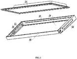
FIG. 2 is a partially exploded view of the door ofFIG. 1 ; -
FIG. 3 is a front view of the door ofFIG. 1 ; -
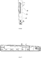
FIG. 4 is a cross-sectional view taken along line A-A ofFIG. 3 ; -
FIG. 5 is a partially enlarged view of position B ofFIG. 4 ; -
FIG. 6 is an enlarged left view of the door ofFIG. 3 ; -
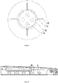
FIG. 7 is a perspective view of an upper molding strip of the door ofFIG. 1 , whereupon a cap is removed; -
FIG. 8 is a partially enlarged view of positon C ofFIG. 7 ; -
FIG. 9 is a perspective view of an upper molding strip ofFIG. 7 , whereupon the cap is mounted; -
FIG. 10 is a partially enlarged view of positon D ofFIG. 9 ; -
FIG. 11 is an exploded perspective view of the upper molding strip ofFIG. 7 ; -
FIG. 12 is a partially enlarged view of positon E ofFIG. 11 . - The present invention will be described in detail below in conjunction with specific embodiments shown in the figures. However, these embodiments are not intended to limit the present invention. Variations in structures, methods or functions made by those having ordinary skill in the art according to these embodiments are all comprised in the extent of protection of the present invention.
- In the depictions of the specific embodiments of the present invention, directional or positional relationship as indicted by terms such as "up", "down", "front", "rear", "left", "right", "vertical", "horizontal", "bottom", "in" and "out" is based on the directional or positional relationship shown in the figures usually with reference to the normal in-use state of the refrigerator, and does not indicate that the designated position or element must be in a specific direction.
- Moreover, it should be appreciated that although the terms such as "first" and "second" may be used to describe various elements or structures herein, the described objects should not be limited by the above terms. The above terms are only used to distinguish the described objects from each other. For example, a first side plate may also be referred to as a second side plate, and also the second side plate may also be referred to as the first side plate, which does not depart from the extent of protection of the present invention.
- As shown in
FIG. 1 , an embodiment of the present invention provides a refrigerator comprising a cabinet (not shown) and adoor 10 connected to the cabinet, wherein the cabinet defines a storage space, and thedoor 10 is operable to open or close at least part of the storage space. The storage space may comprise a plurality of storage components whose number and structural forms may be configured according to different needs. The storage components usually comprise a refrigerating chamber and a freezing chamber. - Further referring to
FIG. 1 through FIG. 5 , thedoor 10 comprises adoor frame 12 enclosed at the periphery, and afirst side plate 14 and asecond side plate 16 located on two opposed sides of thedoor frame 12, thedoor frame 12, thefirst side plate 14 and thesecond side plate 16 forming areceiving space 23 for receiving a foaming material. Thedoor frame 12 is provided with at least one material overflow preventing assembly which comprises anair discharge hole 18 disposed on thedoor frame 12, a receivingcavity 20 communicated with theair discharge hole 18, and amaterial discharging passage 22 communicated with thereceiving cavity 20, theair discharge hole 18 is communicated with the external, and thematerial discharging passage 22 is communicated with thereceiving space 23. - In the present preferred embodiment, the material overflow preventing assembly comprises the
receiving cavity 20 communicated with theair discharge hole 18, and thematerial discharging passage 22 communicated with thereceiving cavity 20, theair discharge hole 18 is communicated with the external, and the materialdischarging passage 22 is communicated with thereceiving space 23. Therefore, the foaming material is in a gelation state upon passing through the materialdischarging passage 22, and gathers in thereceiving cavity 20 after passing through thematerial discharging passage 22. When the foaming material advances forward into the receivingcavity 20 under a pressure, the foaming material will transition from the gelation state to a cured state and the foaming fluidity is very poor, so the foaming material will not overflow through theair discharge hoe 18 out of thedoor frame 12, and the air in thereceiving space 23 after foaming will be discharged through theair discharge hole 18. As such, no foaming material outside thedoor frame 12 need be manually cleaned additionally, thereby substantially reducing the manufacturing cost and improving the quality of products. - Specifically, the
air discharge hole 18 extends along anextension axis 24, a plane perpendicular to theextension axis 24 is defined as a first plane, a projection area of thereceiving cavity 20 on the first plane is greater than a projection area of theair discharge hole 18 on the first plane, and the projection area of thereceiving cavity 20 on the first plane is greater than the projection area of thematerial discharging passage 22 on the first plane. It is further ensured that the foaming material reaches a cured state after passing through the narrowmaterial discharging passage 22, and then entering the wide receivingcavity 20 under a certain pressure, thereby gathering in thereceiving cavity 20 and preventing the overflow of the foaming material. - Further referring to
FIG. 6 through FIG. 12 , each material overflow preventing assembly comprises a plurality ofair discharge holes 18, and projections of the plurality ofair discharge holes 18 on the first plane are all located in a range of the projection of thereceiving cavity 20 on the first plane. In the present preferred embodiment, four air discharge holes 18 are provided, the four air discharge holes 18 are uniformly distributed in the receivingcavity 20, and the four air discharge holes 18 are all set the same so that they can be processed and manufactured conveniently. Certainly, the air discharge holes 18 may be set in another number, and the air discharge holes 18 may also set partially the same and partially different. It is also possible to set all the air discharge holes 18 different from one another. - Furthermore, the projection of the
material discharging passage 22 on the first plane is located out of the range of the projection of the receivingcavity 20 on the first plane. One, two or more material overflow preventing assemblies may also be provided. - Specifically, the material overflow preventing assembly comprises a
protrusion 26 formed on thedoor frame 12 and forming the receivingcavity 20, and acap 28 disposed at the outer circumference of theprotrusion 26 and covering the receivingcavity 20; theprotrusion 26 extends from thedoor frame 12 inward the receivingcavity 23, and thematerial discharging passage 22 is defined between theprotrusion 26 and thecap 28. - In the present embodiment, the
material discharging passage 22 comprises a longitudinal throughslot 30 disposed on the outer circumference of theprotrusion 26 and extending in an extension direction of theprotrusion 26, the longitudinal throughslot 30 is communicated with the receivingspace 23, and remaining outer circumference of theprotrusion 26 except for the longitudinal throughslot 30 abuts against an inner side of thecap 28. Such an arrangement makes the structure simple and easy to manufacture. A plurality of longitudinal throughslots 30 are provided and evenly distributed on the outer circumference of theprotrusion 26. Certainly, the plurality of longitudinal throughslots 30 may not be evenly distributed on the outer circumference of theprotrusion 26. In the present embodiment, four longitudinal throughslots 30 are provided, and may also be set in another number. Theprotrusion 26 is set in a cylindrical shape, and certainly may also be set in another shape. The four longitudinal throughslots 30 are evenly distributed on the outer circumference of theprotrusion 26. Certainly, the four longitudinal throughslots 30 may also be set to be arranged unevenly. In addition, the four longitudinal throughslots 30 are set to be the same so that they can be processed and manufactured conveniently. Likewise, the four longitudinal throughslots 30 may also be set partially the same and partially different. Certainly, the four longitudinal throughslots 30 may also be set different from one another. - In addition, the
material discharging passage 22 may also be set in other structural forms in addition to the longitudinal throughslot 30, so long as a passage is formed between theprotrusion 26 and thecap 28 to communicate the receivingspace 23 with the receivingcavity 20. For example, the longitudinal throughslot 30 is not disposed on the outer circumference of theprotrusion 26, and a certain gap is ensured between the outer circumference of theprotrusion 26 and thecap 28 to form thematerial discharging passage 22 to allow the foaming material and air to pass therethrough. - Referring to
FIG. 1 , thedoor frame 12 comprises anupper molding strip 32, alower molding strip 34 opposed to theupper molding strip 32, aleft side rim 36 and a right side rim 38 opposed to theleft side rim 36, theleft side rim 36 andright side rim 38 are connected to theupper molding strip 32 andlower molding strip 34, and the material overflow preventing assembly is disposed on theupper molding strip 32 and/orlower molding strip 34. In the present embodiment, both theupper molding strip 32 andlower molding strip 34 are provided with the material overflow preventing assembly. The material overflow preventing assemblies on theupper molding strip 32 andlower molding strip 34 may be set to be symmetrical with each other. Certainly, the material overflow preventing assemblies on theupper molding strip 32 andlower molding strip 34 may also be set asymmetrical. In addition, the structural forms of the material overflow preventing assemblies on theupper molding strip 32 andlower molding strip 34 may be set completely the same. Likewise, the structural forms of the material overflow preventing assemblies on theupper molding strip 32 andlower molding strip 34 may also be set not completely the same. - The
air discharge hole 18 comprises a conical hole portion communicated with the receivingcavity 20 and a round hole portion connected with the conical hole portion, the round hole portion being connected with the external. Such an arrangement enables a better air-discharging performance and better prevents the overflow of the material. - Furthermore, the
cap 28 comprises anedge portion 40 abutting against thedoor frame 12 and abottom portion 42 opposed to theedge portion 40, thebottom portion 42 is used to enclose the receivingcavity 20, thematerial discharging passage 22 further comprises agroove 44 disposed on thedoor frame 12 and communicated with the longitudinal throughslot 30, and an extension direction of thegroove 44 is perpendicular to the extension direction of the longitudinal throughslot 30. Each longitudinal throughslot 30 is communicated with thegroove 44 so that the foaming material and air enter the longitudinal throughslot 30 through thegroove 44 and then enter the receivingcavity 20. - The present invention further provides a method of manufacturing a
door 10 for a refrigerator, wherein the method comprises: - providing a
door frame 12 enclosed at a periphery; - providing a
first side plate 14 attached to a side of thedoor frame 12; - injecting a foaming material into a receiving
space 23 formed by thedoor frame 12 and thefirst side plate 14; - providing a
second side plate 16 attached to the other side of thedoor frame 12 to enclose the receivingspace 23; - the
door frame 12 is provided with at least one material overflow preventing assembly which comprises anair discharge hole 18 disposed on thedoor frame 12, a receivingcavity 20 communicated with theair discharge hole 18, and amaterial discharging passage 22 communicated with the receivingcavity 20, wherein theair discharge hole 18 is communicated with the external, and thematerial discharging passage 22 is communicated with the receivingspace 23. After the foaming material flows into the receivingcavity 20 through thematerial discharging passage 22, the foaming material is in a gelation state upon passing through thematerial discharging passage 22 and gets cured upon reaching the interior of the receivingcavity 20, and air in the receivingspace 23 is discharged out through theair discharge hole 18 after foaming. - In the present preferred embodiment, the
first side plate 14 is a front panel forming the front of thedoor 10, and thesecond side plate 16 is a door liner forming the rear of thedoor 10. Certainly, thefirst side plate 14 may also set as the door liner forming the rear of thedoor 10, and correspondingly, thesecond side plate 16 is set as the front panel forming the front of thedoor 10. In the manufacturing process, a mold is used to attach thefirst side plate 14 to thedoor frame 12, then the foaming material is injected, then the mold is used to mount thesecond side plate 16, and finally the foaming material foams and expands. Partial foaming material enters the receivingspace 20 as air is pushed and pressed, and gets cured in the receivingspace 20, and air is discharged out through theair discharge port 18, thereby preventing the overflow of the foaming material so that no foaming material need be manually cleaned, reducing the processing and manufacturing cost, making thedoor 10 pleasant in appearance and improving the quality of products. - It should be understood that although the description is described according to the embodiments, not every embodiment only comprises one independent technical solution, that such a description manner is only for the sake of clarity, that those skilled in the art should take the description as an integral part, and that the technical solutions in the embodiments may be suitably combined to form other embodiments understandable by those skilled in the art.
- The detailed descriptions set forth above are merely specific illustrations of feasible embodiments of the present invention, and are not intended to limit the scope of protection of the present invention. All equivalent embodiments or modifications that do not depart from the art spirit of the present invention should fall within the scope of protection of the present invention.
Claims (12)
- A door for a refrigerator, the door comprising a door frame enclosed at a periphery, and a first side plate and a second side plate located on two opposed sides of the door frame, the door frame, the first side plate and the second side plate forming a receiving space for receiving a foaming material, wherein
the door frame is provided with at least one material overflow preventing assembly which comprises an air discharge hole disposed on the door frame, a receiving cavity communicated with the air discharge hole, and a material discharging passage communicated with the receiving cavity, the air discharge hole is communicated with the external, and the material discharging passage is communicated with the receiving space. - The door according to claim 1, wherein the air discharge hole extends along an extension axis, a plane perpendicular to the extension axis is defined as a first plane, a projection area of the receiving cavity on the first plane is greater than a projection area of the air discharge hole on the first plane, and the projection area of the receiving cavity on the first plane is greater than the projection area of the material discharging passage on the first plane.
- The door according to claim 2, wherein each material overflow preventing assembly comprises a plurality of air discharge holes, and projections of the plurality of air discharge holes on the first plane are all located in a range of the projection of the receiving cavity on the first plane.
- The door according to claim 2, wherein the projection of the material discharging passage on the first plane is located out of the range of the projection of the receiving cavity on the first plane.
- The door according to claim 1, wherein the material overflow preventing assembly comprises a protrusion formed on the door frame and forming the receiving cavity, and a cap disposed at an outer circumference of the protrusion and covering the receiving cavity, and wherein the protrusion extends from the door frame inward the receiving cavity, and the material discharging passage is defined between the protrusion and the cap.
- The door according to claim 5, wherein the material discharging passage comprises a longitudinal through slot disposed on the outer circumference of the protrusion and extending in an extension direction of the protrusion, the longitudinal through slot is communicated with the receiving space, and remaining outer circumference of the protrusion except for the longitudinal through slot abuts against an inner side of the cap.
- The door according to claim 6, wherein a plurality of longitudinal through slots are provided and evenly distributed on the outer circumference of the protrusion.
- The door according to claim 6, wherein the cap comprises an edge portion abutting against the door frame and a bottom portion opposed to the edge portion, the material discharging passage further comprises a groove disposed on the door frame and communicated with the longitudinal through slot, and an extension direction of the groove is perpendicular to the extension direction of the longitudinal through slot.
- The door according to claim 1, wherein the door frame comprises an upper molding strip, a lower molding strip opposed to the upper molding strip, a left side rim and a right side rim opposed to the left side rim, the left side rim and right side rim are connected to the upper molding strip and lower molding strip, and the material overflow preventing assembly is disposed on the upper molding strip and/or lower molding strip.
- The door according to claim 1, wherein the air discharge hole comprises a conical hole portion communicated with the receiving cavity and a round hole portion connected with the conical hole portion, the round hole portion being connected with the external.
- A refrigerator, comprising a cabinet a defining a storage space, and a door connected to the cabinet to open or close at least part of the storage space, wherein the door is set as the door according to any of claims 1-10.
- A method of manufacturing a door for a refrigerator, wherein the method comprises:providing a door frame enclosed at a periphery;providing a first side plate attached to a side of the door frame;injecting a foaming material into a receiving space formed by the door frame and the first side plate;providing a second side plate attached to the other side of the door frame to enclose the receiving space;the door frame is provided with at least one material overflow preventing assembly which comprises an air discharge hole disposed on the door frame, a receiving cavity communicated with the air discharge hole, and a material discharging passage communicated with the receiving cavity; the air discharge hole is communicated with the external, and the material discharging passage is communicated with the receiving space; after the foaming material flows into the receiving cavity through the material discharging passage, the foaming material is in a gelation state upon passing through the material discharging passage and gets cured upon reaching the interior of the receiving cavity, and air in the receiving space is discharged out through the air discharge hole after foaming.
Applications Claiming Priority (2)
| Application Number | Priority Date | Filing Date | Title |
|---|---|---|---|
| CN201910489324.9A CN112050543B (en) | 2019-06-06 | 2019-06-06 | Door body for refrigerator, refrigerator and manufacturing method of door body |
| PCT/CN2019/111179 WO2020244114A1 (en) | 2019-06-06 | 2019-10-15 | Door body for refrigerator, refrigerator and manufacturing method of door body |
Publications (3)
| Publication Number | Publication Date |
|---|---|
| EP3982070A1 true EP3982070A1 (en) | 2022-04-13 |
| EP3982070A4 EP3982070A4 (en) | 2022-07-20 |
| EP3982070B1 EP3982070B1 (en) | 2024-12-25 |
Family
ID=73608888
Family Applications (1)
| Application Number | Title | Priority Date | Filing Date |
|---|---|---|---|
| EP19931607.6A Active EP3982070B1 (en) | 2019-06-06 | 2019-10-15 | Door body for refrigerator, refrigerator and manufacturing method of door body |
Country Status (5)
| Country | Link |
|---|---|
| US (1) | US11796244B2 (en) |
| EP (1) | EP3982070B1 (en) |
| KR (1) | KR102782918B1 (en) |
| CN (1) | CN112050543B (en) |
| WO (1) | WO2020244114A1 (en) |
Family Cites Families (40)
| Publication number | Priority date | Publication date | Assignee | Title |
|---|---|---|---|---|
| DE2558058C3 (en) * | 1975-12-22 | 1979-08-30 | Blasius 7455 Jungingen Speidel | Drain valve for blood pressure meters and the like |
| US4102721A (en) * | 1976-10-13 | 1978-07-25 | Minnesota Mining And Manufacturing Company | Barrier tape construction |
| JPS54164961U (en) * | 1978-05-11 | 1979-11-19 | ||
| JPS6042526A (en) * | 1984-07-02 | 1985-03-06 | Hitachi Ltd | dehumidifier water receptor |
| FR2644390B1 (en) * | 1989-03-17 | 1991-09-13 | Selnor Electromenager Nord | DEGASSING DEVICE FOR APPARATUS TO BE FILLED WITH FOAM AND APPARATUS COMPRISING SUCH A DEGASSING DEVICE |
| US4955675A (en) * | 1989-04-17 | 1990-09-11 | White Consolidated Industries, Inc. | Hinged panels with foamed-in-place insulation |
| US5103528A (en) * | 1991-02-12 | 1992-04-14 | Illinois Tool Works Inc. | Refrigeration, foam sealing bushing |
| US5560695A (en) * | 1991-08-26 | 1996-10-01 | Southco, Inc. | Venting device |
| DE4242777A1 (en) * | 1992-12-17 | 1994-06-23 | Bosch Siemens Hausgeraete | Insulating wall |
| JPH06238639A (en) * | 1993-02-19 | 1994-08-30 | C C A Kk | PATTERNED MOLDED BODY MOLDING APPARATUS, AND PATTERNED MOLDED BODY |
| US5740074A (en) * | 1996-08-01 | 1998-04-14 | General Electric Company | Method for filling a compartment cavity with foam |
| CA2273476C (en) * | 1999-05-27 | 2004-07-13 | Camco Inc. | Refrigerator door corner construction |
| USD517900S1 (en) * | 2002-04-04 | 2006-03-28 | 420820 Ontario Limited | Bushing |
| US7886500B2 (en) * | 2005-05-27 | 2011-02-15 | Maytag Corporation | Refrigerator door with ratcheting end cap |
| US8104853B2 (en) * | 2006-12-19 | 2012-01-31 | Samsung Electronics Co., Ltd. | Refrigerator and method of manufacturing door thereof |
| KR20080065837A (en) * | 2007-01-10 | 2008-07-15 | 삼성전자주식회사 | Refrigerator |
| DE102010027918A1 (en) * | 2010-04-19 | 2011-10-20 | BSH Bosch und Siemens Hausgeräte GmbH | Door leaf, method for producing a door leaf and refrigeration device with a door leaf |
| JP5014508B1 (en) * | 2011-11-30 | 2012-08-29 | 株式会社ブリヂストン | Method for producing foam molded article |
| JP5912544B2 (en) * | 2012-01-11 | 2016-04-27 | 株式会社ジェイエスピー | Method for producing foamed article with skin |
| US9132592B2 (en) * | 2012-11-19 | 2015-09-15 | General Electric Company | Appliance with expanding foam material |
| JP6211920B2 (en) * | 2013-12-25 | 2017-10-11 | 株式会社ジェイエスピー | Method for producing foamed article with skin |
| US9970701B2 (en) * | 2014-01-07 | 2018-05-15 | Samsung Electronics Co., Ltd. | Refrigerator having a heating pipe |
| US9435579B1 (en) * | 2015-04-10 | 2016-09-06 | Electrolux Home Products, Inc. | Insulated door assembly |
| CN104949444A (en) * | 2015-06-26 | 2015-09-30 | 合肥美的电冰箱有限公司 | Refrigerator door end cover, refrigerator door body assembly and refrigerator |
| CN205192065U (en) * | 2015-11-30 | 2016-04-27 | 青岛海尔股份有限公司 | Door body used for refrigerator and refrigerator |
| CN105371575B (en) * | 2015-12-01 | 2018-09-04 | 青岛海尔股份有限公司 | refrigerator door |
| KR101738787B1 (en) * | 2015-12-15 | 2017-06-08 | 엘지전자 주식회사 | Vacuum adiabatic body, container, container for vehicle, and vehicle |
| CN205300095U (en) | 2015-12-24 | 2016-06-08 | 海信容声(广东)冰箱有限公司 | Cold storage plant door body |
| KR101810760B1 (en) * | 2016-01-05 | 2017-12-19 | 엘지전자 주식회사 | Refirgerator and control merthod thereof |
| CN106288619B (en) * | 2016-07-29 | 2019-01-18 | 青岛海尔股份有限公司 | Refrigerator and door body thereof |
| CN106839639B (en) * | 2016-12-27 | 2021-04-16 | 青岛海尔特种电冰柜有限公司 | Freezer Thermometers and Freezers |
| WO2018136053A1 (en) * | 2017-01-18 | 2018-07-26 | Whirlpool Corporation | Increased vacuum port area for achieving faster vacuum evacuation time in vacuum insulated structures |
| CN206817867U (en) * | 2017-06-26 | 2017-12-29 | 合肥美菱股份有限公司 | A kind of door body panel with gas port |
| AU2019270066B2 (en) * | 2018-05-16 | 2022-06-09 | Lg Electronics Inc. | Clothing treatment device |
| CN208909875U (en) * | 2018-06-20 | 2019-05-31 | 佛山市顺德区美的电热电器制造有限公司 | Foam breaker, pot lid and cooking utensil for cooking utensils |
| CN208909735U (en) * | 2018-06-20 | 2019-05-31 | 佛山市顺德区美的电热电器制造有限公司 | Pot cover for cooking apparatus and the cooking apparatus with it |
| CN208704274U (en) * | 2018-08-15 | 2019-04-05 | Tcl家用电器(合肥)有限公司 | Refrigerator and its door |
| WO2020170163A1 (en) * | 2019-02-19 | 2020-08-27 | Proprietect L.P. | Composite foam article |
| CN111609654B (en) * | 2019-02-25 | 2022-03-08 | Lg电子株式会社 | Entrance refrigerator and refrigerator |
| CN217031770U (en) * | 2021-09-08 | 2022-07-22 | 青岛海尔电冰箱有限公司 | Door body for refrigerator and refrigerator |
-
2019
- 2019-06-06 CN CN201910489324.9A patent/CN112050543B/en active Active
- 2019-10-15 KR KR1020217039785A patent/KR102782918B1/en active Active
- 2019-10-15 EP EP19931607.6A patent/EP3982070B1/en active Active
- 2019-10-15 US US17/616,637 patent/US11796244B2/en active Active
- 2019-10-15 WO PCT/CN2019/111179 patent/WO2020244114A1/en not_active Ceased
Also Published As
| Publication number | Publication date |
|---|---|
| CN112050543B (en) | 2021-11-26 |
| US11796244B2 (en) | 2023-10-24 |
| EP3982070B1 (en) | 2024-12-25 |
| US20220228797A1 (en) | 2022-07-21 |
| KR102782918B1 (en) | 2025-03-14 |
| EP3982070A4 (en) | 2022-07-20 |
| CN112050543A (en) | 2020-12-08 |
| WO2020244114A1 (en) | 2020-12-10 |
| KR20220002655A (en) | 2022-01-06 |
Similar Documents
| Publication | Publication Date | Title |
|---|---|---|
| US20160348957A1 (en) | Refrigerator appliances and mullions therefor | |
| EP4140384A1 (en) | Dishwasher | |
| EP3106802A1 (en) | Depth-adjustable ice compartment for refrigerator and method for manufacturing the same | |
| US11796244B2 (en) | Door for refrigerator, refrigerator and method of manufacturing the door | |
| EP2514350A1 (en) | Door for a household appliance and household appliance | |
| EP3733010B1 (en) | Safety helmet and manufacturing method therefor | |
| CN110524790B (en) | Middle frame manufacturing method, middle frame and electronic equipment | |
| CN205192065U (en) | Door body used for refrigerator and refrigerator | |
| MXPA04007667A (en) | Mould for tv chassis and tv frames. | |
| CN111434930B (en) | Fan frame | |
| CN207456011U (en) | For the door and refrigerator of refrigerator | |
| CN109813032A (en) | Foaming cover board, refrigerator doors end cap and refrigerator | |
| KR20230122440A (en) | High-speed molding device | |
| CN217047566U (en) | Moulding mould for herringbone mop | |
| US6693679B1 (en) | Monitor front case with gate landings | |
| CN104296474A (en) | Shell component and refrigerator counter door with same | |
| KR20190112603A (en) | Indoor unit of air conditioner | |
| CN106766609B (en) | Assembled liner components, refrigeration equipment boxes and refrigeration equipment | |
| CN206729446U (en) | Cutlery box | |
| CN224001686U (en) | Water box and clothes treatment equipment | |
| KR200348440Y1 (en) | The shelf of refrigerator | |
| JPH08142230A (en) | Cabinet device and manufacturing method thereof | |
| KR0169612B1 (en) | Attachment structure of cold storage | |
| CN209345412U (en) | A kind of structure of new type plastic plated item | |
| KR19990029526U (en) | Air Vent on Refrigerator Door |
Legal Events
| Date | Code | Title | Description |
|---|---|---|---|
| STAA | Information on the status of an ep patent application or granted ep patent |
Free format text: STATUS: THE INTERNATIONAL PUBLICATION HAS BEEN MADE |
|
| PUAI | Public reference made under article 153(3) epc to a published international application that has entered the european phase |
Free format text: ORIGINAL CODE: 0009012 |
|
| STAA | Information on the status of an ep patent application or granted ep patent |
Free format text: STATUS: REQUEST FOR EXAMINATION WAS MADE |
|
| 17P | Request for examination filed |
Effective date: 20211206 |
|
| AK | Designated contracting states |
Kind code of ref document: A1 Designated state(s): AL AT BE BG CH CY CZ DE DK EE ES FI FR GB GR HR HU IE IS IT LI LT LU LV MC MK MT NL NO PL PT RO RS SE SI SK SM TR |
|
| REG | Reference to a national code |
Ref country code: DE Ref legal event code: R079 Free format text: PREVIOUS MAIN CLASS: F25D0023100000 Ipc: F25D0023020000 Ref country code: DE Ref legal event code: R079 Ref document number: 602019064111 Country of ref document: DE Free format text: PREVIOUS MAIN CLASS: F25D0023100000 Ipc: F25D0023020000 |
|
| A4 | Supplementary search report drawn up and despatched |
Effective date: 20220615 |
|
| RIC1 | Information provided on ipc code assigned before grant |
Ipc: F25D 23/02 20060101AFI20220611BHEP |
|
| DAV | Request for validation of the european patent (deleted) | ||
| DAX | Request for extension of the european patent (deleted) | ||
| GRAP | Despatch of communication of intention to grant a patent |
Free format text: ORIGINAL CODE: EPIDOSNIGR1 |
|
| STAA | Information on the status of an ep patent application or granted ep patent |
Free format text: STATUS: GRANT OF PATENT IS INTENDED |
|
| INTG | Intention to grant announced |
Effective date: 20240718 |
|
| GRAS | Grant fee paid |
Free format text: ORIGINAL CODE: EPIDOSNIGR3 |
|
| GRAA | (expected) grant |
Free format text: ORIGINAL CODE: 0009210 |
|
| STAA | Information on the status of an ep patent application or granted ep patent |
Free format text: STATUS: THE PATENT HAS BEEN GRANTED |
|
| AK | Designated contracting states |
Kind code of ref document: B1 Designated state(s): AL AT BE BG CH CY CZ DE DK EE ES FI FR GB GR HR HU IE IS IT LI LT LU LV MC MK MT NL NO PL PT RO RS SE SI SK SM TR |
|
| REG | Reference to a national code |
Ref country code: GB Ref legal event code: FG4D |
|
| REG | Reference to a national code |
Ref country code: CH Ref legal event code: EP |
|
| REG | Reference to a national code |
Ref country code: DE Ref legal event code: R096 Ref document number: 602019064111 Country of ref document: DE |
|
| REG | Reference to a national code |
Ref country code: IE Ref legal event code: FG4D |
|
| REG | Reference to a national code |
Ref country code: LT Ref legal event code: MG9D |
|
| PG25 | Lapsed in a contracting state [announced via postgrant information from national office to epo] |
Ref country code: HR Free format text: LAPSE BECAUSE OF FAILURE TO SUBMIT A TRANSLATION OF THE DESCRIPTION OR TO PAY THE FEE WITHIN THE PRESCRIBED TIME-LIMIT Effective date: 20241225 |
|
| PG25 | Lapsed in a contracting state [announced via postgrant information from national office to epo] |
Ref country code: FI Free format text: LAPSE BECAUSE OF FAILURE TO SUBMIT A TRANSLATION OF THE DESCRIPTION OR TO PAY THE FEE WITHIN THE PRESCRIBED TIME-LIMIT Effective date: 20241225 |
|
| PG25 | Lapsed in a contracting state [announced via postgrant information from national office to epo] |
Ref country code: BG Free format text: LAPSE BECAUSE OF FAILURE TO SUBMIT A TRANSLATION OF THE DESCRIPTION OR TO PAY THE FEE WITHIN THE PRESCRIBED TIME-LIMIT Effective date: 20241225 |
|
| PG25 | Lapsed in a contracting state [announced via postgrant information from national office to epo] |
Ref country code: NO Free format text: LAPSE BECAUSE OF FAILURE TO SUBMIT A TRANSLATION OF THE DESCRIPTION OR TO PAY THE FEE WITHIN THE PRESCRIBED TIME-LIMIT Effective date: 20250325 |
|
| PG25 | Lapsed in a contracting state [announced via postgrant information from national office to epo] |
Ref country code: LV Free format text: LAPSE BECAUSE OF FAILURE TO SUBMIT A TRANSLATION OF THE DESCRIPTION OR TO PAY THE FEE WITHIN THE PRESCRIBED TIME-LIMIT Effective date: 20241225 Ref country code: GR Free format text: LAPSE BECAUSE OF FAILURE TO SUBMIT A TRANSLATION OF THE DESCRIPTION OR TO PAY THE FEE WITHIN THE PRESCRIBED TIME-LIMIT Effective date: 20250326 |
|
| PG25 | Lapsed in a contracting state [announced via postgrant information from national office to epo] |
Ref country code: RS Free format text: LAPSE BECAUSE OF FAILURE TO SUBMIT A TRANSLATION OF THE DESCRIPTION OR TO PAY THE FEE WITHIN THE PRESCRIBED TIME-LIMIT Effective date: 20250325 |
|
| REG | Reference to a national code |
Ref country code: NL Ref legal event code: MP Effective date: 20241225 |
|
| PG25 | Lapsed in a contracting state [announced via postgrant information from national office to epo] |
Ref country code: NL Free format text: LAPSE BECAUSE OF FAILURE TO SUBMIT A TRANSLATION OF THE DESCRIPTION OR TO PAY THE FEE WITHIN THE PRESCRIBED TIME-LIMIT Effective date: 20241225 |
|
| REG | Reference to a national code |
Ref country code: AT Ref legal event code: MK05 Ref document number: 1754462 Country of ref document: AT Kind code of ref document: T Effective date: 20241225 |
|
| PG25 | Lapsed in a contracting state [announced via postgrant information from national office to epo] |
Ref country code: SM Free format text: LAPSE BECAUSE OF FAILURE TO SUBMIT A TRANSLATION OF THE DESCRIPTION OR TO PAY THE FEE WITHIN THE PRESCRIBED TIME-LIMIT Effective date: 20241225 |
|
| PG25 | Lapsed in a contracting state [announced via postgrant information from national office to epo] |
Ref country code: PL Free format text: LAPSE BECAUSE OF FAILURE TO SUBMIT A TRANSLATION OF THE DESCRIPTION OR TO PAY THE FEE WITHIN THE PRESCRIBED TIME-LIMIT Effective date: 20241225 |
|
| PG25 | Lapsed in a contracting state [announced via postgrant information from national office to epo] |
Ref country code: ES Free format text: LAPSE BECAUSE OF FAILURE TO SUBMIT A TRANSLATION OF THE DESCRIPTION OR TO PAY THE FEE WITHIN THE PRESCRIBED TIME-LIMIT Effective date: 20241225 |
|
| PG25 | Lapsed in a contracting state [announced via postgrant information from national office to epo] |
Ref country code: IS Free format text: LAPSE BECAUSE OF FAILURE TO SUBMIT A TRANSLATION OF THE DESCRIPTION OR TO PAY THE FEE WITHIN THE PRESCRIBED TIME-LIMIT Effective date: 20250425 |
|
| PG25 | Lapsed in a contracting state [announced via postgrant information from national office to epo] |
Ref country code: PT Free format text: LAPSE BECAUSE OF FAILURE TO SUBMIT A TRANSLATION OF THE DESCRIPTION OR TO PAY THE FEE WITHIN THE PRESCRIBED TIME-LIMIT Effective date: 20250428 |
|
| PG25 | Lapsed in a contracting state [announced via postgrant information from national office to epo] |
Ref country code: EE Free format text: LAPSE BECAUSE OF FAILURE TO SUBMIT A TRANSLATION OF THE DESCRIPTION OR TO PAY THE FEE WITHIN THE PRESCRIBED TIME-LIMIT Effective date: 20241225 |
|
| PG25 | Lapsed in a contracting state [announced via postgrant information from national office to epo] |
Ref country code: RO Free format text: LAPSE BECAUSE OF FAILURE TO SUBMIT A TRANSLATION OF THE DESCRIPTION OR TO PAY THE FEE WITHIN THE PRESCRIBED TIME-LIMIT Effective date: 20241225 Ref country code: AT Free format text: LAPSE BECAUSE OF FAILURE TO SUBMIT A TRANSLATION OF THE DESCRIPTION OR TO PAY THE FEE WITHIN THE PRESCRIBED TIME-LIMIT Effective date: 20241225 |
|
| PG25 | Lapsed in a contracting state [announced via postgrant information from national office to epo] |
Ref country code: SK Free format text: LAPSE BECAUSE OF FAILURE TO SUBMIT A TRANSLATION OF THE DESCRIPTION OR TO PAY THE FEE WITHIN THE PRESCRIBED TIME-LIMIT Effective date: 20241225 |
|
| PG25 | Lapsed in a contracting state [announced via postgrant information from national office to epo] |
Ref country code: CZ Free format text: LAPSE BECAUSE OF FAILURE TO SUBMIT A TRANSLATION OF THE DESCRIPTION OR TO PAY THE FEE WITHIN THE PRESCRIBED TIME-LIMIT Effective date: 20241225 |
|
| PG25 | Lapsed in a contracting state [announced via postgrant information from national office to epo] |
Ref country code: IT Free format text: LAPSE BECAUSE OF FAILURE TO SUBMIT A TRANSLATION OF THE DESCRIPTION OR TO PAY THE FEE WITHIN THE PRESCRIBED TIME-LIMIT Effective date: 20241225 |
|
| PG25 | Lapsed in a contracting state [announced via postgrant information from national office to epo] |
Ref country code: SE Free format text: LAPSE BECAUSE OF FAILURE TO SUBMIT A TRANSLATION OF THE DESCRIPTION OR TO PAY THE FEE WITHIN THE PRESCRIBED TIME-LIMIT Effective date: 20241225 |
|
| REG | Reference to a national code |
Ref country code: DE Ref legal event code: R097 Ref document number: 602019064111 Country of ref document: DE |
|
| PG25 | Lapsed in a contracting state [announced via postgrant information from national office to epo] |
Ref country code: DK Free format text: LAPSE BECAUSE OF FAILURE TO SUBMIT A TRANSLATION OF THE DESCRIPTION OR TO PAY THE FEE WITHIN THE PRESCRIBED TIME-LIMIT Effective date: 20241225 |
|
| PLBE | No opposition filed within time limit |
Free format text: ORIGINAL CODE: 0009261 |
|
| STAA | Information on the status of an ep patent application or granted ep patent |
Free format text: STATUS: NO OPPOSITION FILED WITHIN TIME LIMIT |
|
| REG | Reference to a national code |
Ref country code: CH Ref legal event code: L10 Free format text: ST27 STATUS EVENT CODE: U-0-0-L10-L00 (AS PROVIDED BY THE NATIONAL OFFICE) Effective date: 20251105 |
|
| 26N | No opposition filed |
Effective date: 20250926 |
|
| PGFP | Annual fee paid to national office [announced via postgrant information from national office to epo] |
Ref country code: DE Payment date: 20251015 Year of fee payment: 7 |
|
| PGFP | Annual fee paid to national office [announced via postgrant information from national office to epo] |
Ref country code: GB Payment date: 20251023 Year of fee payment: 7 |
|
| PGFP | Annual fee paid to national office [announced via postgrant information from national office to epo] |
Ref country code: FR Payment date: 20251027 Year of fee payment: 7 |
|
| REG | Reference to a national code |
Ref country code: CH Ref legal event code: H13 Free format text: ST27 STATUS EVENT CODE: U-0-0-H10-H13 (AS PROVIDED BY THE NATIONAL OFFICE) Effective date: 20260527 |
|
| PG25 | Lapsed in a contracting state [announced via postgrant information from national office to epo] |
Ref country code: LU Free format text: LAPSE BECAUSE OF NON-PAYMENT OF DUE FEES Effective date: 20251015 |
|
| REG | Reference to a national code |
Ref country code: BE Ref legal event code: MM Effective date: 20251031 |
|
| PG25 | Lapsed in a contracting state [announced via postgrant information from national office to epo] |
Ref country code: LT Free format text: LAPSE BECAUSE OF FAILURE TO SUBMIT A TRANSLATION OF THE DESCRIPTION OR TO PAY THE FEE WITHIN THE PRESCRIBED TIME-LIMIT Effective date: 20241225 |
|
| PG25 | Lapsed in a contracting state [announced via postgrant information from national office to epo] |
Ref country code: MC Free format text: LAPSE BECAUSE OF FAILURE TO SUBMIT A TRANSLATION OF THE DESCRIPTION OR TO PAY THE FEE WITHIN THE PRESCRIBED TIME-LIMIT Effective date: 20241225 |
|
| PG25 | Lapsed in a contracting state [announced via postgrant information from national office to epo] |
Ref country code: BE Free format text: LAPSE BECAUSE OF NON-PAYMENT OF DUE FEES Effective date: 20251031 Ref country code: CH Free format text: LAPSE BECAUSE OF NON-PAYMENT OF DUE FEES Effective date: 20251031 |